Embed Size (px)
Citation preview

OPERATION MANUAL
25" VIDEO GAMEDEDICATED CABINET
FIRST FLOOR, HEALTHAID HOUSEMARLBOROUGH HILL, HARROWMIDDLESEX HA1 1UDTEL: 020 8427 8427� FAX: 020 8861 1209WWW.SAMMYEUROPE.CO.UK
SAMMY GAME CARTRIDGE SYSTEM
Part#: 53-30-300

CONTENTS
1. SPECIFICATIONS OF CABINET............................. 2,32. GAME PLAY............................................................. 43. GAME SETTING...................................................... 54. CALIBRATION OF GUN SCOPE............................ 65. SYSTEM BOARD ................................................... 7 to 11
EXPANSION CARTRIDGE SLOT 1 .................................................. 7JAMMA CONNECTOR TABLE .................................................. 8SPEAKER VOLUME (SOUND) .................................................. 9MODEM CONNECTOR (SRL) >>> OPTION ............................... 9DIP SWITCH (2 POSITIONS) .................................................. 9STEREO SPEAKER OUTPUT CONNECTOR (OPTION) ............ 10VGA (31KHz) TV SIGNAL OUTPUT CONNECTOR (VDO) >>> OPTION ... 10GAME CARTRIDGE ................................................................... 11
6. SYSTEM MENU ........................................................ 12 to 18TEST MODE ............................................................................... 13, 14COIN SETTING ............................................................................... 15, 16CONFIGURATION ...................................................................... 17BOOKKEEPING ................................................................................ 18BACKUP CLEAR ...................................................................... 18WIRING DIAGRAM FOR GUN CONTROL PANEL ...................... 19

2
1. SPECIFICATIONS OF CABINET
Push Button AssyPlayer 1
Push Button AssyPlayer 2
Sammy Scope Gun Assy
Gun Holster, Scope Gun
Part#: 99-50-010
Part#: 99-50-011
Part#: 53-50-320
Part#: 53-50-304
SIZE: W = 30" (762 mm)D = 37" (940 mm)H = 77" (1956 mm)
WEIGHT: 385 lbs (175 kg)
INPUT POWER: USA&CANADA = 120VAC, 60Hz
Instruction Decal SheetSS USA
Part#: 53-30-210
Marquee, SS USAPart#: 53-30-100
Side Decal, Atomiswave
Part#: 99-30-200
Speaker
TV Monitor Assy

3
Gun Sub Board
Part#: 53-20-700Main PCB, Atomiswave
Part#: 99-10-010
Game Cartridge, SS USA
Part#: 53-90-850
Remote Controller for Monitor
INSIDE VIEW OF CONTROL PANEL & INSTRUCTION PANEL
Connector Bracket
Gun Sub Harness
INSIDE VIEW OF COIN DOOR
Test & ServiceSwitch Bracket
Mars DBAAE2451 (OPTION)
Coin incounter meter

4
2. GAME PLAY
HIT EACH TARGET! DON’T SHOOTBLACK AREA!
DON’T SHOOTRED-X TARGET!
Insert coin(s).Shoot using gun scope to select Category fromSPEED, PRECISION, MARKSMAN, and TRAINING.
Each DIVISION has 8 stages. Shoot and hit each target to get points.Register your initials when you rank in top 20.
Shoot using gun scope to choose DIVISION from 4 kinds.(OPEN, STANDARD, MODIFIED and REVOLVER. Each division uses a different GUN.)
SPEED: Mainly Steel targets PRECISION: Mainly Human shaped targetsMARKSMAN: Mainly Bullseye type targetsTRAINING: Mix of above targets. (Easy)
SPEED & PRECISION(Competitor, Trojan, Edge and Revolver w/compensator)
MARKSMAN(Grandmaster, Xcaliber, Executive and Revolver w/scope)
3. GAME SETTING
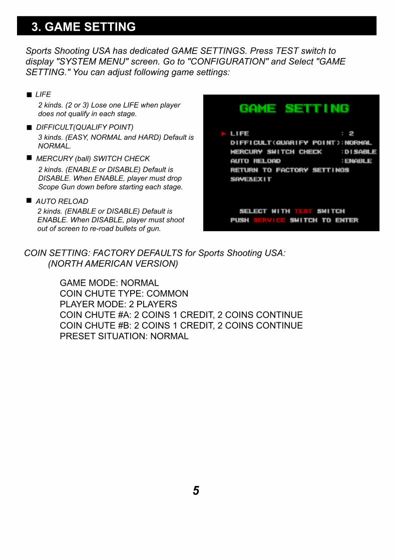
Sports Shooting USA has dedicated GAME SETTINGS. Press TEST switch to display "SYSTEM MENU" screen. Go to "CONFIGURATION" and Select "GAME SETTING." You can adjust following game settings:
LIFE
DIFFICULT(QUALIFY POINT)
2 kinds. (2 or 3) Lose one LIFE when player does not qualify in each stage.
3 kinds. (EASY, NORMAL and HARD) Default isNORMAL.
MERCURY (ball) SWITCH CHECK
2 kinds. (ENABLE or DISABLE) Default isDISABLE. When ENABLE, player must dropScope Gun down before starting each stage.
AUTO RELOAD2 kinds. (ENABLE or DISABLE) Default isENABLE. When DISABLE, player must shootout of screen to re-road bullets of gun.
COIN SETTING: FACTORY DEFAULTS for Sports Shooting USA:(NORTH AMERICAN VERSION)
GAME MODE: NORMALCOIN CHUTE TYPE: COMMONPLAYER MODE: 2 PLAYERSCOIN CHUTE #A: 2 COINS 1 CREDIT, 2 COINS CONTINUECOIN CHUTE #B: 2 COINS 1 CREDIT, 2 COINS CONTINUEPRESET SITUATION: NORMAL
5
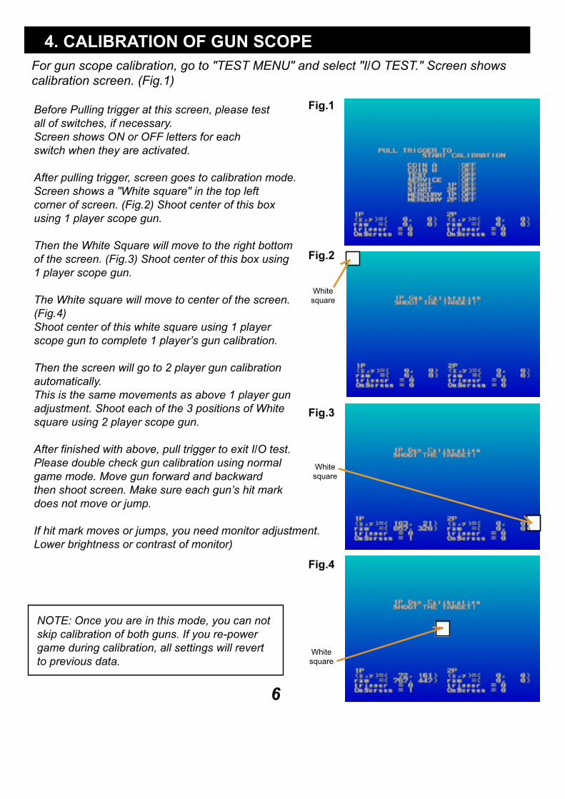
For gun scope calibration, go to "TEST MENU" and select "I/O TEST." Screen shows calibration screen. (Fig.1)
Before Pulling trigger at this screen, please testall of switches, if necessary.Screen shows ON or OFF letters for eachswitch when they are activated.
After pulling trigger, screen goes to calibration mode.Screen shows a "White square" in the top leftcorner of screen. (Fig.2) Shoot center of this boxusing 1 player scope gun.
Then the White Square will move to the right bottomof the screen. (Fig.3) Shoot center of this box using1 player scope gun.
The White square will move to center of the screen.(Fig.4)Shoot center of this white square using 1 playerscope gun to complete 1 player’s gun calibration.
Then the screen will go to 2 player gun calibrationautomatically.This is the same movements as above 1 player gunadjustment. Shoot each of the 3 positions of Whitesquare using 2 player scope gun.
After finished with above, pull trigger to exit I/O test.Please double check gun calibration using normalgame mode. Move gun forward and backwardthen shoot screen. Make sure each gun’s hit markdoes not move or jump.
If hit mark moves or jumps, you need monitor adjustment.Lower brightness or contrast of monitor)
NOTE: Once you are in this mode, you can notskip calibration of both guns. If you re-powergame during calibration, all settings will revertto previous data.
4. CALIBRATION OF GUN SCOPE
Fig.1
Fig.2
Fig.3
Fig.4
6
Whitesquare
Whitesquare
Whitesquare

GAME CARTRIDGE
EXPANSION CARTRIDGE SLOT 2(OPTION)
MOUNTING BRACKET
FAN
SPEAKER VOLUME (SOUND)
MODEM CONNECTOR(SRL)
VGA OUTPUT (VDO)
STEREO SPEAKEROUTPUT & SERIAL TERMINAL(CN3)
DIPSW(TV RESOLUTION AND TEST MODE)
EXPANSION CARTRIDGE SLOT 1(EX. I/O BOARD) CONNECTOR TABLE
JAMMA CONNECTOR
7
5. SYSTEM BOARD
DIMENSIONS: 10.67"W x 9.04" D x 2.52" HWEIGHT: 3 lbs
PIN# FUNCTION PIN# FUNCTION1 23 45 67 89 10
11 1213 1415 1617 1819 2021 2223 2425 2627 28
CN302: 28 PIN CONNECTOR
PIN# FUNCTION123456789
10
PIN# FUNCTION123456789
10
CN304: 12 PIN CONNECTOR
CN303: 8 PIN CONNECTOR
+5VDC
+5VDC
GND
GND
ANALOG 0
ANALOG 1
ANALOG 2
ANALOG 3
1112
+5VDC
+5VDC
GND
GND
POUT 0
POUT 1
POUT 2
POUT 3
POUT 4
POUT 5
POUT 6
POUT 7
+5VDC +5VDC
GND GND
3P GUN
3PUP/PULX1
3P COIN
3P START
3PPU1/TRIG
3P PUSH2
3P PUSH3
3P PUSH4
3P PUSH5
4P GUN
4PUP/PULX1
3PDO/PULX2
3PLE/PULY1
3PRI/PULY2
4PDO/PULX2
4PLE/PULY1
4PRI/PULY2
4P COIN
4P START
4PPU1/TRIG
4P PUSH2
4P PUSH3
4P PUSH4
4P PUSH5

1 6 8 28
JAMMA CONNECTOR TABLE
JAMMA EDGE CONNECTOR (56 PINS)
No. FUNCTION I/O FUNCTION I/O123456789
10111213141516171819202122232425262728
--
ININ-
IN-
OUTOUTOUTOUTOUTOUT
-ININININININININININININ--
--
ININ-
IN-
OUTOUTOUT
-OUTOUTINININININININININININININ--
GNDGND
5V5V
N.C.12V
N.C.1P COIN COUNTER 1P COIN LOCKOUTMONO SPEAKER AUDIO OUTVIDEO REDVIDEO BLUEVIDEO GNDTEST SW1P COIN1P START1P UP1P DOWN1P LEFT1P RIGHT1P PUSH11P PUSH21P PUSH31P PUSH41P PUSH5GNDGND
GNDGND
5V5V
N.C.12V
N.C.2P COIN COUNTER 2P COIN LOCKOUTMONO SPEAKER AUDIO GNDVIDEO GREENVIDEO SYNCSERVICE SWTILT SW2P COIN2P START2P UP2P DOWN2P LEFT2P RIGHT2P PUSH12P PUSH22P PUSH32P PUSH42P PUSH5GNDGND
No.ABCDEFHJKLMNPRSTUVWXYZabcdef
The other side of PIN1 is "PIN A"
8

SOUND
9 6
5 1
SRL
2 1
SWON
OFF
No. I/O123456789
-IN
OUTOUT
--
OUTIN-
N.C.RXD2TXD2DTRGNDN.C.
RTSCTSN.C.
ON OFFSW-1
SW-2
15KHZ31KHZ
SPEAKER VOLUME (SOUND)
LOW HIGH
MODEM CONNECTOR (SRL) >>> OPTION
JST 9PIN SUB, CONNECTOR (MALE)
SW-1: Change Frequency of TV signal.Default is OFF = 15KHz**For Standard = Low resolutionmonitor
SW-2: Change ON position to go to SYSTEM MENU.
SYSTEM MENUMODE
GAMEMODE
Use for adjusting game sound
FUNCTION
9
DIP SWITCH (2 POSITIONS)
CN3
10
9 1
2
VDO11
6 10
15
1 5
No. I/O123456789
101112131415
OUTOUTOUT
-----
OUT---
OUT--
RGBN.C.GNDR-GNDG-GNDB-GND+5VGNDN.C.N.C.COMP SYNCN.C.N.C.
No. I/O13579
OUTOUTOUTOUT
-
STEREO SPEAKER L +STEREO SPEAKER L -STEREO SPEAKER R +STEREO SPEAKER R -N.C.
No. I/O2468
10
OUTIN-
OUT-
TXDRXDGND+5VN.C.
10
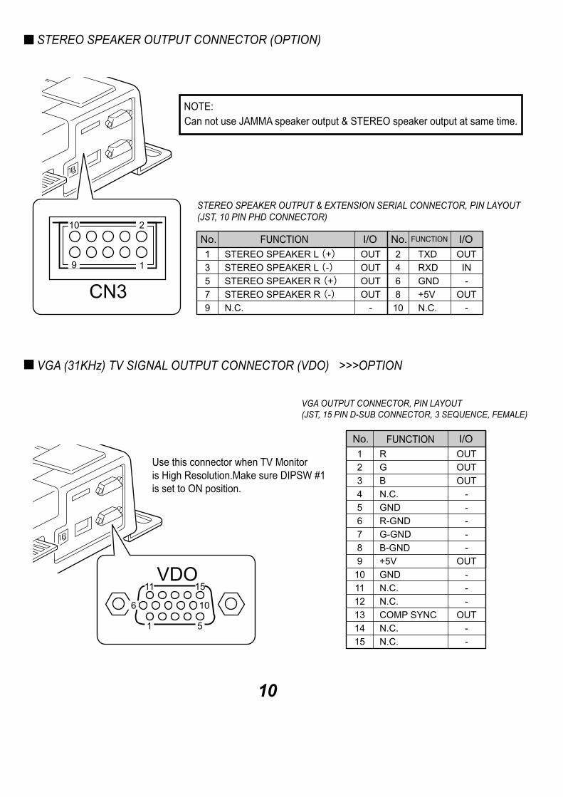
STEREO SPEAKER OUTPUT CONNECTOR (OPTION)
Can not use JAMMA speaker output & STEREO speaker output at same time.NOTE:
STEREO SPEAKER OUTPUT & EXTENSION SERIAL CONNECTOR, PIN LAYOUT(JST, 10 PIN PHD CONNECTOR)
FUNCTION FUNCTION
VGA (31KHz) TV SIGNAL OUTPUT CONNECTOR (VDO) >>>OPTION
Use this connector when TV Monitoris High Resolution.Make sure DIPSW #1is set to ON position.
VGA OUTPUT CONNECTOR, PIN LAYOUT(JST, 15 PIN D-SUB CONNECTOR, 3 SEQUENCE, FEMALE)
FUNCTION
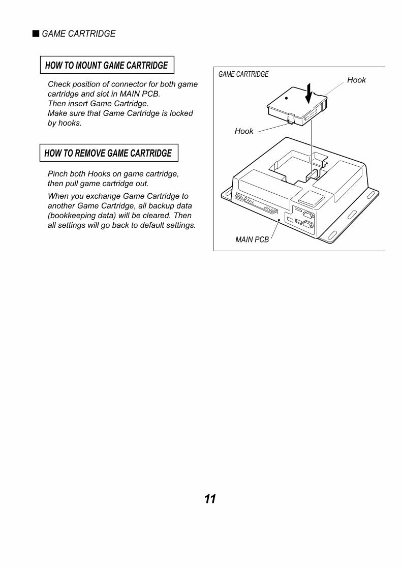
Check position of connector for both gamecartridge and slot in MAIN PCB.Then insert Game Cartridge.Make sure that Game Cartridge is lockedby hooks.
Hook
HOW TO MOUNT GAME CARTRIDGEGAME CARTRIDGE
MAIN PCB
Pinch both Hooks on game cartridge,then pull game cartridge out.
HOW TO REMOVE GAME CARTRIDGE
Hook
When you exchange Game Cartridge toanother Game Cartridge, all backup data(bookkeeping data) will be cleared. Thenall settings will go back to default settings.
MAIN PCB CASE include FAN for heat exhausting.Please make clearance of over 2" between FAN and back of any object when you mountMAIN PCB to cabinet.
Over 2"
Heat exhausting FAN
Do not position FAN to close to bottom of cabinet. As this will an over heating issue.NOTE:
11
GAME CARTRIDGE
FAN

FLOW CHART
12
6. SYSTEM MENU
(If there is no TEST switch in your cabinet, change DIPSW #2 ON, re-power on to go to SYSTEM MENU. Press 1P START switch quickly to move cursor. Press & hold 1P START button to select it.)
HOW TO CONTROLPress TEST switch to move cursor. Press SERVICE switch to select.
Press TEST switch to enter SYSTEM MENU.(TEST switch can be activated any time. Game play will cancel when you press a testswitch during game play. Credit(s) will be lost.)
BOOKKEEPING

TOP PAGE OF SYSTEM MENU
This is first screen of SYSTEM MENU.
Move cursor to contents then select togo to next menu
Move cursor to "EXIT" and select togo back to normal game mode.Credit(s) are memorized.
TEST MODEUse for function test of game.
Select "EXIT" to go back to top page screen of SYSTEM MENU.
13
COLOR TEST
Use for Color adjustment and checking ofmonitor.
Press SERVICE switch to go back toTEST MODE screen
CROSS HATCH
Use for Size adjustment of monitor.
Press SERVICE switch to go back toTEST MODE screen
I/O TESTUse for functions of input devices.I/O TEST contents will be deferent gameby game. (Picture shows basic I/O screen)Activate each input device manually.If it’s functioned, letter on screen "OFF"change to "ON."Press SERVICE switch to go back toTEST MODE screen
14
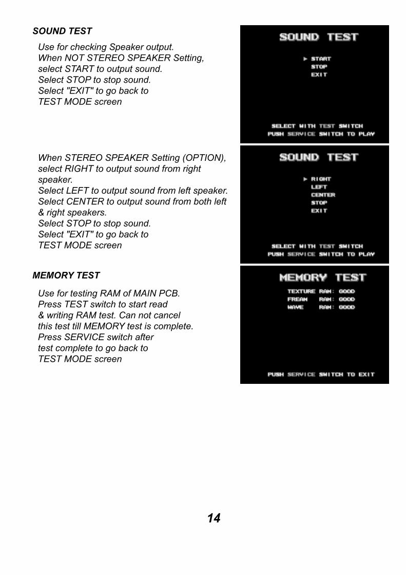
SOUND TEST
Use for checking Speaker output.When NOT STEREO SPEAKER Setting,select START to output sound.Select STOP to stop sound.Select "EXIT" to go back toTEST MODE screen
When STEREO SPEAKER Setting (OPTION),select RIGHT to output sound from rightspeaker.Select LEFT to output sound from left speaker.Select CENTER to output sound from both left& right speakers.Select STOP to stop sound.Select "EXIT" to go back toTEST MODE screen
MEMORY TEST
Use for testing RAM of MAIN PCB.Press TEST switch to start read& writing RAM test. Can not cancelthis test till MEMORY test is complete.Press SERVICE switch aftertest complete to go back toTEST MODE screen
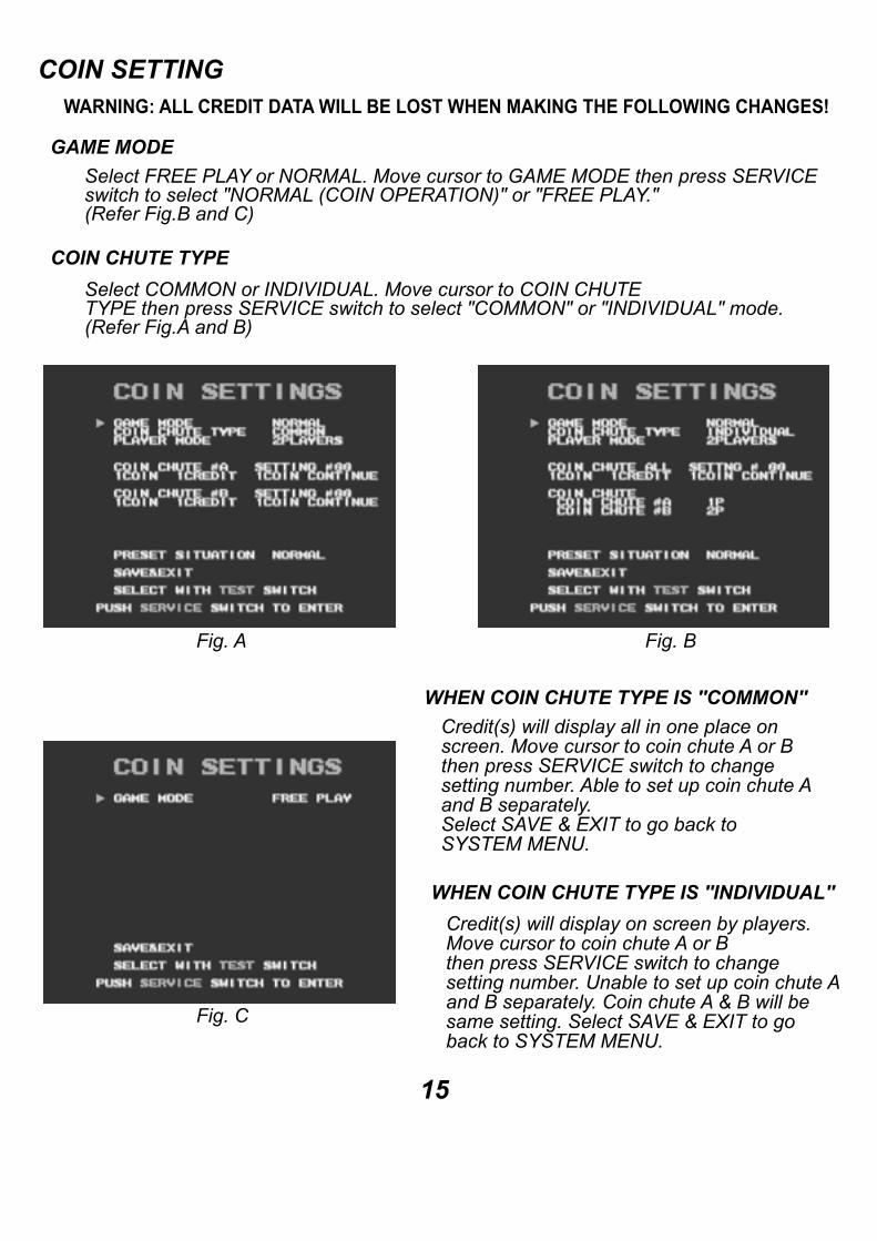
COIN SETTINGWARNING: ALL CREDIT DATA WILL BE LOST WHEN MAKING THE FOLLOWING CHANGES!
GAME MODESelect FREE PLAY or NORMAL. Move cursor to GAME MODE then press SERVICEswitch to select "NORMAL (COIN OPERATION)" or "FREE PLAY."(Refer Fig.B and C)
Fig. A Fig. B
Fig. C
Select COMMON or INDIVIDUAL. Move cursor to COIN CHUTETYPE then press SERVICE switch to select "COMMON" or "INDIVIDUAL" mode.(Refer Fig.A and B)
COIN CHUTE TYPE
15
WHEN COIN CHUTE TYPE IS "COMMON" Credit(s) will display all in one place onscreen. Move cursor to coin chute A or Bthen press SERVICE switch to changesetting number. Able to set up coin chute Aand B separately.Select SAVE & EXIT to go back toSYSTEM MENU.
WHEN COIN CHUTE TYPE IS "INDIVIDUAL"
Credit(s) will display on screen by players.Move cursor to coin chute A or Bthen press SERVICE switch to changesetting number. Unable to set up coin chute Aand B separately. Coin chute A & B will besame setting. Select SAVE & EXIT to goback to SYSTEM MENU.

16
There is 53 kinds of coin settings.When PRESET SITUATION is NORMAL,you can select from 14 kinds. (#00 to #09 and#45 to #48.) This is basic coin settings line-up.When PRESET SITUATION is ADVANCE,you can choose from all 53 kinds as shownbelow.
NO COIN SETTING#00 1 COIN 1 CREDIT / 1 COIN CONTINUE#01 2 COINS 1 CREDIT / 1 COIN CONTINUE#02 2 COINS 1 CREDIT / 2 COINS CONTINUE#03 3 COINS 1 CREDIT / 1 COIN CONTINUE#04 3 COINS 1 CREDIT / 2 COINS CONTINUE#05 3 COINS 1 CREDIT / 3 COINS CONTINUE#06 4 COINS 1 CREDIT / 1 COIN CONTINUE#07 4 COINS 1 CREDIT / 2 COINS CONTINUE#08 4 COINS 1 CREDIT / 3 COINS CONTINUE#09 4 COINS 1 CREDIT / 4 COINS CONTINUE#10 5 COINS 1 CREDIT / 1 COIN CONTINUE#11 5 COINS 1 CREDIT / 2 COINS CONTINUE#12 5 COINS 1 CREDIT / 3 COINS CONTINUE#13 5 COINS 1 CREDIT / 4 COINS CONTINUE#14 5 COINS 1 CREDIT / 5 COINS CONTINUE#15 6 COINS 1 CREDIT / 1 COIN CONTINUE#16 6 COINS 1 CREDIT / 2 COINS CONTINUE#17 6 COINS 1 CREDIT / 3 COINS CONTINUE#18 6 COINS 1 CREDIT / 4 COINS CONTINUE#19 6 COINS 1 CREDIT / 5 COINS CONTINUE#20 6 COINS 1 CREDIT / 6 COINS CONTINUE#21 7 COINS 1 CREDIT / 1 COIN CONTINUE#22 7 COINS 1 CREDIT / 2 COINS CONTINUE#23 7 COINS 1 CREDIT / 3 COINS CONTINUE#24 7 COINS 1 CREDIT / 4 COINS CONTINUE#25 7 COINS 1 CREDIT / 5 COINS CONTINUE#26 7 COINS 1 CREDIT / 6 COINS CONTINUE#27 7 COINS 1 CREDIT / 7 COINS CONTINUE
NO COIN SETTING#28 8 COINS 1 CREDIT / 1 COIN CONTINUE#29 8 COINS 1 CREDIT / 2 COINS CONTINUE#30 8 COINS 1 CREDIT / 3 COINS CONTINUE#31 8 COINS 1 CREDIT / 4 COINS CONTINUE#32 8 COINS 1 CREDIT / 5 COINS CONTINUE#33 8 COINS 1 CREDIT / 6 COINS CONTINUE#34 8 COINS 1 CREDIT / 7 COINS CONTINUE#35 8 COINS 1 CREDIT / 8 COINS CONTINUE#36 9 COINS 1 CREDIT / 1 COIN CONTINUE#37 9 COINS 1 CREDIT / 2 COINS CONTINUE#38 9 COINS 1 CREDIT / 3 COINS CONTINUE#39 9 COINS 1 CREDIT / 4 COINS CONTINUE#40 9 COINS 1 CREDIT / 5 COINS CONTINUE#41 9 COINS 1 CREDIT / 6 COINS CONTINUE#42 9 COINS 1 CREDIT / 7 COINS CONTINUE#43 9 COINS 1 CREDIT / 8 COINS CONTINUE#44 9 COINS 1 CREDIT / 9 COINS CONTINUE#45 1 COIN 2 CREDITS#46 1 COIN 3 CREDITS#47 1 COIN 4 CREDITS#48 1 COIN 5 CREDITS#49 1 COIN 6 CREDITS#50 1 COIN 7 CREDITS#51 1 COIN 8 CREDITS#52 1 COIN 9 CREDITS
PRESET SITUATION
PLAYER MODE
Choose from 2 PLAYERS or 4 PLAYERS. When 2 PLAYERS, COIN CHUTE A (Left) is for1 Player, COIN CHUTE B (Right) is for 2 player.When 4 PLAYERS, COIN CHUTE A (Left) for 1 & 2 players, COIN CHUTE B (Right) for3 & 4 players.

CONFIGURATION4 kinds of contents.Contents of "COMMUNICATION" isunavailable when game has noCOMMUNICATION feature.
SYSTEM SETTINGS
AREA: Select country of operation. (JAPAN, NORTH AMERICA, EUROPE or OTHER)This setting effects factory defaults.
LANGUAGE: Select from following:(English or Japanese)
ADVERTISE SOUND:Select to output sound in attract mode.
AUDIO MODE:Select sound STEREO (OPTION) or NORMAL
SOUND VOLUME:Volume level of sound. Default is "15"
17
CLOCK SETTING
Adjust clock system on Main PCB.Move cursor then press SERVICE switchto advance each digit. Press & holdSERVICE switch more than 1 sec. tospeed it up.
Move cursor to "SAVE & EXIT" then pressSERVICE switch to go back to SYSTEMMENU screen.
GAME SETTING
Adjust game setting at this mode.Move cursor to "SAVE & EXIT" then press SERVICE switch to go back toCONFIGURATION.Select "RETURN TO FACTORY SETTINGS" to change all settings toFactory default settings.

18
BOOKKEEPINGSRAM on Main PCB records & saves following data.
TOTAL TIME: This is time when game is powered on.TOTAL PLAY TIME: Play time.COIN #A: Total coins of COIN CHUTE 1.COIN #B: Total coins of COIN CHUTE 2.TOTAL COIN: Total coins of COIN #A + COIN #B.COIN CREDIT: Number of credits by coins in.SERVICE CREDIT: Number of SERVICE credits.TOTAL CREDIT: Total of COINS + SERVICE CREDITS.NORMAL START: Number of games started from beginning.CONTINUE START: Number of Continue plays.NETWORK START: Number of NETWORK plays.
BACKUP CLEAR
Clear following data in MAIN PCB.(HIGH SCORE, CREDIT CLEAR,BOOKKEEPING CLEAR and ALL CLEAR)
Press SERVICE to select each contents thengo to each data clear screen.
In each data clear screen, Press TEST switchto move cursor to "YES" then pressSERVICE switch. After finishing data clear,screen will go back to BACKUP CLEAR screen.
NETWORK SETTING (OPTION)
Press SERVICE to select each contents.
Move cursor to CANCEL & EXIT then press SERVICE switchto go back to SYSTEM MENU without saving changes.
Move cursor to SAVE & EXIT then press SERVICE switchto go back to SYSTEM MENU with saving changes.

(1P PUMP SW)(1P PUMP SW GND)
GUN SUB BOARD
(1P TRIGGER SW)
1P GUN OPTICAL
(2P PUMP SW)(2P PUMP SW GND)
(2P TRIGGER SW)
2P GUN OPTICAL
CONNECTOR BRACKET (INSIDE OF CONTROL PANEL)
CONTROL PANEL ASSY
SPORTS SHOOTING USA, WIRING DIAGRAM FOR GUN CONTROL PANEL
GUN SUB HARNESS
19