Embed Size (px)
Citation preview
HMP-1093 E△4 (1/14)
Operation Manual
E3P Pump
HMP-1093E
Please read this manual before you use this pump.
Sumitomo Precision Products Co., Ltd. Industrial Hydraulic Department
Please contact the following department concerning any problem or question.
Tokyo Head Office
Sumitomo Corporation Takebashi Bldg 4th floor, 1-2-2 Hitotsubashi, Chiyoda-ku,
Tokyo 100-0003, Japan
Phone 81- (0) 3-3217-2813 Fax 81- (0) 3 -3217-2823
Nagoya Sales Office
INO Bldg. 2-29 Otemachi, Kariya City, Aichi 448-0857, Japan
Phone 81- (0) 566-27-2350 or 81- (0) 566-27-2351 Fax 81- (0) 566-27-2360
Head Office & Main Plant
1-10 Fuso-cho, Amagasaki, Hyogo 660-0891, Japan
Phone 81- (0) 6-6489-5946 Fax 81- (0) 6489-5902
HMP-1093 E△4 (2/14)
--- Contents ---
1. Before use 3
1) Introduction 3
2) Comparison with the article 3
3) Safety matters 3
2. Notes concerning safety
3
1) Notes on mounting, removal, installation of product 3
2) During operation 4
3) Maintenance 4
3. Notes on handling and use 5
1) Explanation about Model No. 5
2) Suction pressure of pump 5
3) Piping 5
4) Wiring 5
5) Outlet pressure 7
6) Coolant 7
7) Operation environment 8
4. Notes on operation 8
1) Cleaning inside the tank 8
2) Putting coolant 8
3) Confirmation of rotating direction 8
4) Start the operation of pump 8
5) Trial operation 9
5. Maintenance procedure 9
6. Troubleshooting 10
7. Disassembly, assembly and repair 10
HMP-1093 E△4 (3/14)
1. Before use 1) Introduction
Before use, please read this Operation Manual carefully and use E3P Pump after you
understand all the contents.
a) This Operation Manual is for correct and safe use of E3P Pump.
b) Please observe method of use and restrictions described in this Operation Manual.
c) Method of use not described in this Operation Manual and use deviating from the
restrictions described in this Operation Manual will result in a risk of human injury
and/or damage to property due to stop of function and/or damage of pump, etc..
Do not use E3P Pump in a method not described in this Operation Manual
and/or deviating from the restrictions described in this Operation Manual.
If you use E3P Pump in a method not described in this Operation Manual,
it is fully due to your responsibility.
d) As a result of design change or improvement, the product you bought may differ
from the contents described in this Operation Manual.
e) If you have any question about E3P Pump you bought or the contents of
this Operation Manual, please do not hesitate to contact us.
2) Comparison with the article
When you receive E3P Pump, please compare your order with model
number written in the nameplate of Coolant Pump and motor.
3) Safety matters
In this Operation Manual, necessary matters to use this E3P Pump correctly
and safely are marked with the following symbols.
! DANGER : Serious danger which may result in death or serious injury if not
avoided.
! WARNING : Potential danger which may result in death or serious injury if not
avoided.
! CAUTION : Potential danger which may result in minor or moderate injury or
damage to property.
2. Notes concerning safety
1) Notes on mounting, removal and installation of product
For mounting, please hang by means of hanging bolt of motor and just bolt the motor
to mounting base by means of mounting holes of feet or flange of motor.
Since not only weight of pump and motor but also motive load during operation will apply to
mounting base, it may cause vibration. Therefore, mounting base must be of solid
construction.
! DANGER : When you carry the pump, please do not lift the pump up by hands.
Please make sure to use hanging bolt of motor and hang the pump up
by whist, etc..
While you hang and carry the product (the product is being hung),
please do not approach it.
HMP-1093 E△4 (4/14)
! WARNING : When using hanging bolts, please use them after you check they are
firmly tightened. After installation of product to the machine, please
do not hang up the whole machine by hanging bolts of motor.
It may result in damage to hanging bolts, injury due to overturn, and
damage of the machine.
! WARNING : Please do not lift up only the pump sides and do not subject it to
impact. It may cause trouble.
! WARNING : Personnel having expertise must mount, remove and install the
product.
! WARNING : Before mounting, removal and installation of the product, please make
sure to turn the power OFF and take action to remove the remaining
pressure in the circuit. After operation, since Pump, motor
and coolant may be very hot, please take that action after you check
an appropriate temperature (30℃~40℃) is achieved.
! WARNING : Please do not put flammable objects around the motor. It may cause
a risk of fire.
! WARNING : Please do not put objects which disturb free air draft around the
motor.
It will disturb the cooling and it may cause a risk of explosion, fire or
scald due to abnormal heating.
! CAUTION : Please do not get on, beat or apply a force to the product.
It may cause an human injury and/or damage to product.
2) During operation
! WARNING : Please use product within the range of specified operating conditions
such as ambient temperature, temperature of coolant, etc..
If you use beyond this range, it may cause malfunction, damage to
product and fire.
! WARNING : In case of power failure, make sure to stop the operation immediately.
In case of sudden recovery, the pump and the motor may begin to
work and it may cause human injury.
! WARNING : In case of abnormal condition, make sure to stop the operation
immediately.
It may cause a risk of electrical shock, human injury and fire.
! CAUTION : Since the pump and the motor becomes very hot during operation,
please do not touch them by bare hands.
3) Maintenance
! CAUTION : Please do not disassemble or reconstruct the product without our
approval in writing. If the product is disassembled or reconstructed
without our approval, since it is beyond the scope of our warranty,
we shall not have no responsibility to such disassembly or
reconstruction.
HMP-1093 E△4 (5/14)
3. Notes on handling and use
! CAUTION : Please observe the following cautions for handling and use.
1) Explanation of Model number
E3P – 16 – 1.5 – *
Basic type Design number
Motor output
Theoretical displacement
(cm3/rev)
2) Suction pressure of pump
Please set the suction pressure of pump to –0.03~+0.03MPa (-0.3~+0.3kgf/cm2).
3) Piping
a) Please make sure to lay a pipe of suction and relief return line into coolant not to suck air.
b) Please make sure to lay a pipe of suction not to suck sludge of tank bottom.
c) Please make sure not to suck coolant from relief retun directly.
d) For suction line, please set the flowing speed in the pipe to within 1.5m/sec.
e) Please make sure that constrained force by piping does not apply to the pump.
f) In order to reduce vibration and noise of the unit and to avoid constraint force on the pump,
we recommend you to use rubber hose in pressure line.
g) Please install the pipes after washed by acid and neutralized in advance.
h) If you use an optional flange, pressure gauge can be installed on the flange.
4) Wiring
! WARNING : Please check the voltage and frequency written in nameplate are
consistent with those you supply.
It may cause a risk of burn or fire.
! WARNING : Please connect the power cable and lead wire of motor according to
connection diagram in terminal box or Operation Manual.
Otherwise, it may cause a risk of electric shock and/or fire.
! WARNING : Do not bend, pull, or pinch the power cable or lead wire of motor
forcibly.
It may cause a risk of electrical shock.
! WARNING : Wiring must be conducted by personnel having expertise.
It may cause a risk of burn or fire.
! WARNING : When measuring insulation resistance, do not touch the terminals.
It may cause a risk of electrical shock.
! WARNING : Please note motor is not provided with protection device.
Please make sure to provide overload protection device.
We recommend you also provide protection device other than for
overload(earth leakage breaker etc.).
! WARNING : Make sure to ground the earth terminal.
Otherwise, it may cause a risk of electrical shock.
HMP-1093 E△4 (6/14)
a) Power cable
・ If the wiring distance is long, because voltage drop becomes high, make sure to use the wire
of appropriate diameter.
・ Please wire so that the cable is not damaged at cable inlet during operation.
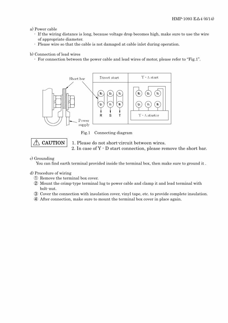
b) Connection of lead wires
・ For connection between the power cable and lead wires of motor, please refer to “Fig.1”.
Fig.1 Connecting diagram
! CAUTION 1. Please do not short-circuit between wires.
2. In case of Y - D start connection, please remove the short bar.
c) Grounding
You can find earth terminal provided inside the terminal box, then make sure to ground it .
d) Procedure of wiring
① Remove the terminal box cover.
② Mount the crimp-type terminal lug to power cable and clamp it and lead terminal with
bolt・nut.
③ Cover the connection with insulation cover, vinyl tape, etc. to provide complete insulation.
④ After connection, make sure to mount the terminal box cover in place again.
HMP-1093 E△4 (7/14)
5) Outlet Pressure
a) Maximum working pressure varies according to combination of pump and motor. Please
refer to “Table 1”. You can not use the pump at the condition exceeding maximum
working pressure and 100% of motor load. ( You can use the pump at the condition
exceeding 100% of motor load according to working condition. Please contact us.)
b) Surge pressure
When you turn the solenoid valve ON and OFF, surge pressure occurs on pressure line
and it will have a bad influence to the pump or other equipment. Give your
consideration to design of circuit to avoid surge pressure possibly.
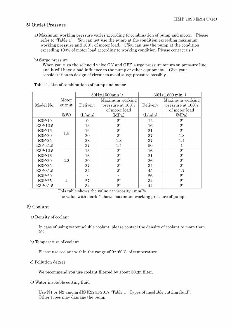
Table 1. List of combinations of pump and motor
Model No.
Motor
output
50Hz(1500min-1) 60Hz(1800 min-1)
Delivery
Maximum working
pressure at 100%
of motor load
Delivery
Maximum working
pressure at 100%
of motor load
(kW) (L/min) (MPa) (L/min) (MPa)
E3P-10
1.5
9 2* 12 2*
E3P-12.5 13 2* 16 2*
E3P-16 16 2* 21 2*
E3P-20 20 2* 27 1.8
E3P-25 28 1.8 37 1.4
E3P-31.5 37 1.4 50 1
E3P-12.5
E3P-16
E3P-20
E3P-25
E3P-31.5
2.2
13
16
20
2*
2*
2*
16
21
26
34
45
2*
2*
2*
2*
1.7
27 2*
34 2*
E3P-20
E3P-25
E3P-31.5
4
-
27
34
-
2*
2*
26
34
44
2*
2*
2*
This table shows the value at viscosity 1mm2/s.
The value with mark * shows maximum working pressure of pump.
6) Coolant
a) Density of coolant
In case of using water-soluble coolant, please control the density of coolant to more than
2%.
b) Temperature of coolant
Please use coolant within the range of 0~60℃ of temperature.
c) Pollution degree
We recommend you use coolant filtered by about 30μm filter.
d) Water-insoluble cutting fluid
Use N1 or N2 among JIS K2241:2017 “Table 1 - Types of insoluble cutting fluid”.
Other types may damage the pump.
HMP-1093 E△4 (8/14)
7) Operation environment
! DANGER : Please do not use in explosive atmosphere. Otherwise, it may cause a
risk of fire and human injury.
Please do not use in unusual environment such as high temperature and high humidity , etc..
Please use under the following conditions.
Ambient temperature: -15~50℃
Relative humidity : 0~95%RH
This product is intended for indoor use.
Please contact us for use under special environment.
4. Notes on operation
1) Cleaning inside the tank
Please clean the inside of tank before putting coolant into the tank.
2) Putting coolant
a) Please put clean coolant sufficiently.
b) If putting coolant by electrical pump, etc., the coolant may foam.
In this case, operate the pump after foam fade outs.
3) Confirmation of rotating direction
! CAUTION : If operating with reverse rotation, pump function may be impaired.
Please confirm the rotating direction by that of motor fan. The correct rotating direction of
motor fan is clockwise.
When checking the rotation, make sure to operate the motor with no load for 5~10 times
intermittently. Make sure that operating time of motor during intermittent operation is
0.5~1 second.
4) Start the operation of pump
! CAUTION : Please avoid to operate in the condition of no coolant in the pump.
it may cause the damage inside the pump.
Before the start of pump, air in suction pipe must be released.
For the first operation of the unit or operation after replacement of coolant or cleaning of suction
filter, please release the air as follows and start the continuous operation.
a) Start the inching of pump
① Check the tank is filled with coolant and loosen the adjusting screw of relief valve to let
the pressure with no load.
② Operate the motor with no load for 5~10 times intermittently. Make sure that
operating time of motor during intermittent operation is 0.5~1 second.
③ When you repeat inching, noise of suction of air will fade out gradually. After the
noise fade outs, start the continuous operation. If noise of suction of air does not
fade out, there is a leakage of air in suction pipe.
HMP-1093 E△4 (9/14)
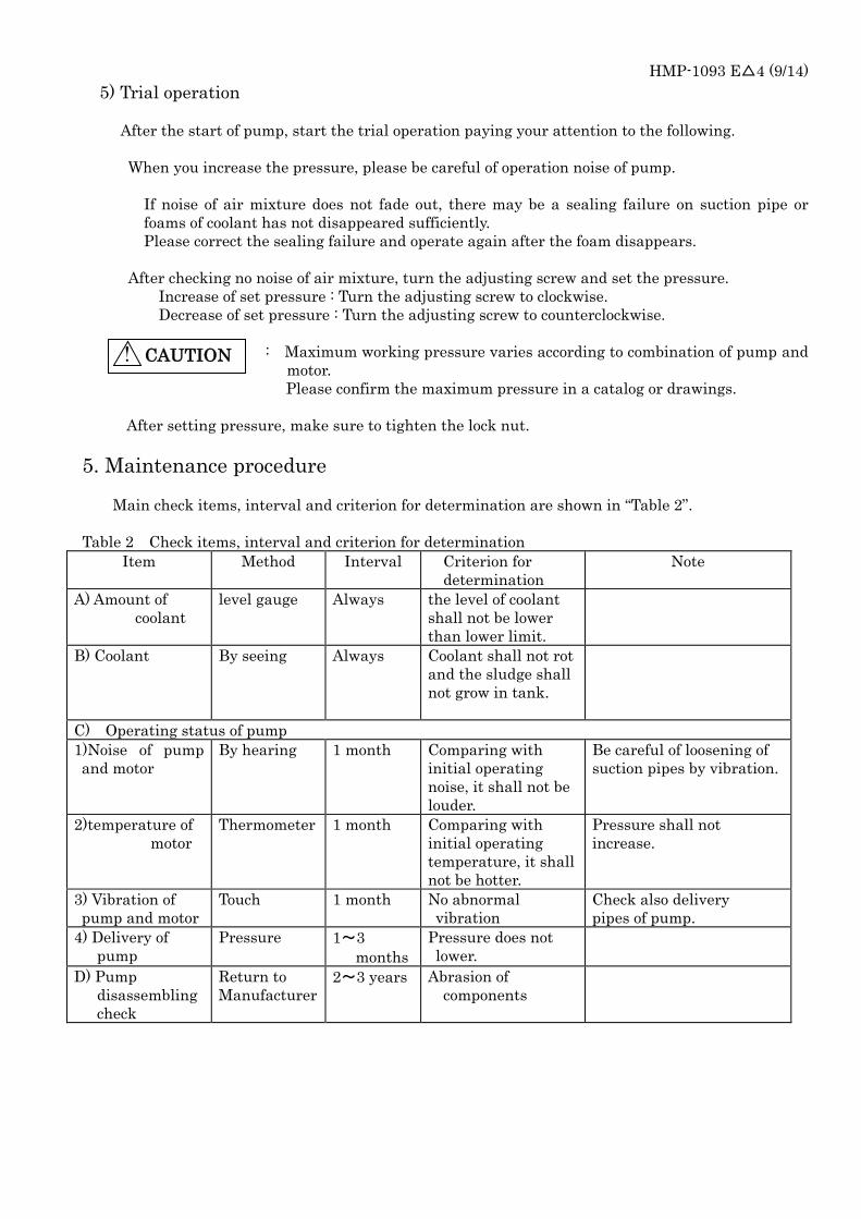
5) Trial operation
After the start of pump, start the trial operation paying your attention to the following.
When you increase the pressure, please be careful of operation noise of pump.
If noise of air mixture does not fade out, there may be a sealing failure on suction pipe or
foams of coolant has not disappeared sufficiently.
Please correct the sealing failure and operate again after the foam disappears.
After checking no noise of air mixture, turn the adjusting screw and set the pressure.
Increase of set pressure : Turn the adjusting screw to clockwise.
Decrease of set pressure : Turn the adjusting screw to counterclockwise.
: Maximum working pressure varies according to combination of pump and
motor.
Please confirm the maximum pressure in a catalog or drawings.
After setting pressure, make sure to tighten the lock nut.
5. Maintenance procedure
Main check items, interval and criterion for determination are shown in “Table 2”.
Table 2 Check items, interval and criterion for determination
Item Method Interval Criterion for
determination
Note
A) Amount of
coolant
level gauge Always the level of coolant
shall not be lower
than lower limit.
B) Coolant
By seeing Always Coolant shall not rot
and the sludge shall
not grow in tank.
C) Operating status of pump
1)Noise of pump
and motor
By hearing 1 month Comparing with
initial operating
noise, it shall not be
louder.
Be careful of loosening of
suction pipes by vibration.
2)temperature of
motor
Thermometer 1 month Comparing with
initial operating
temperature, it shall
not be hotter.
Pressure shall not
increase.
3) Vibration of
pump and motor
Touch 1 month No abnormal
vibration
Check also delivery
pipes of pump.
4) Delivery of
pump
Pressure 1~3
months
Pressure does not
lower.
D) Pump
disassembling
check
Return to
Manufacturer
2~3 years Abrasion of
components
! CAUTION
HMP-1093 E△4 (10/14)
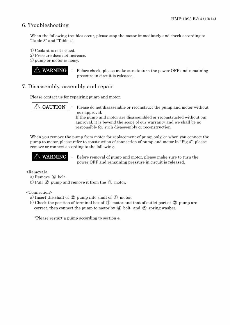
6. Troubleshooting
When the following troubles occur, please stop the motor immediately and check according to
“Table 3” and “Table 4”.
1) Coolant is not issued.
2) Pressure does not increase.
3) pump or motor is noisy.
! WARNING : Before check, please make sure to turn the power OFF and remaining
pressure in circuit is released.
7. Disassembly, assembly and repair
Please contact us for repairing pump and motor.
! CAUTION : Please do not disassemble or reconstruct the pump and motor without
our approval.
If the pump and motor are disassembled or reconstructed without our
approval, it is beyond the scope of our warranty and we shall be no
responsible for such disassembly or reconstruction.
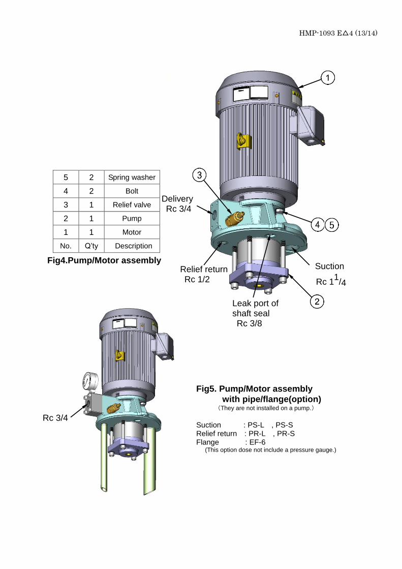
When you remove the pump from motor for replacement of pump only, or when you connect the
pump to motor, please refer to construction of connection of pump and motor in “Fig.4”, please
remove or connect according to the following.
! WARNING : Before removal of pump and motor, please make sure to turn the
power OFF and remaining pressure in circuit is released.
<Removal>
a) Remove ④ bolt.
b) Pull ② pump and remove it from the ① motor.
<Connection>
a) Insert the shaft of ② pump into shaft of ① motor.
b) Check the position of terminal box of ① motor and that of outlet port of ② pump are
correct, then connect the pump to motor by ④ bolt and ⑤ spring washer.
*Please restart a pump according to section 4.
HMP-1093 E△4 (11/14)
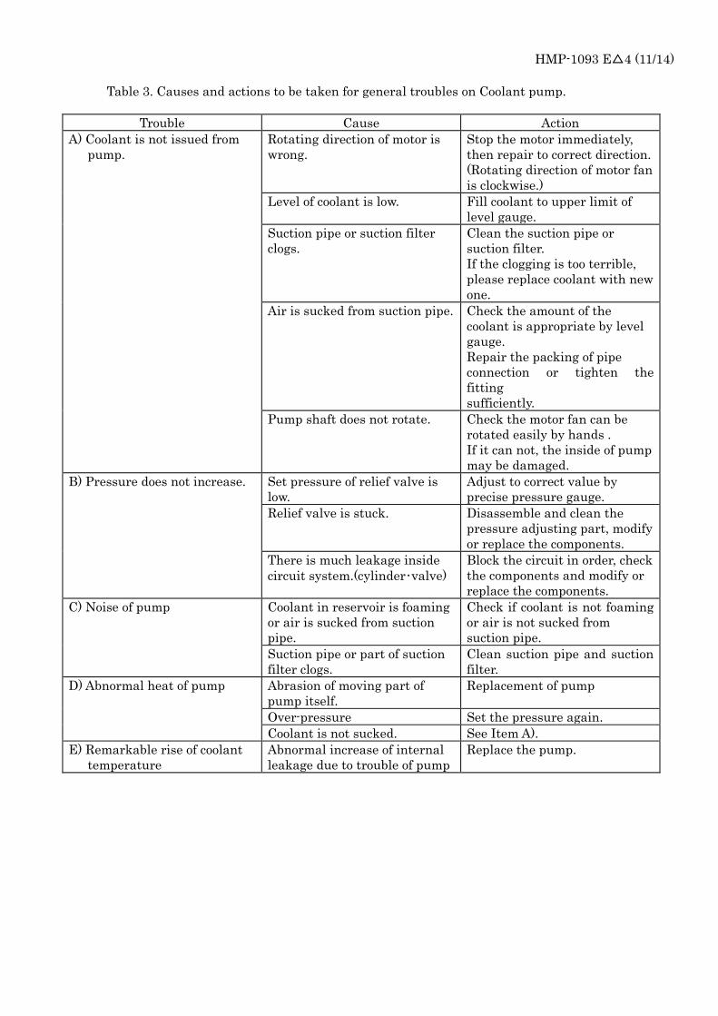
Table 3. Causes and actions to be taken for general troubles on Coolant pump.
Trouble Cause Action
A) Coolant is not issued from
pump.
Rotating direction of motor is
wrong.
Stop the motor immediately,
then repair to correct direction.
(Rotating direction of motor fan
is clockwise.)
Level of coolant is low. Fill coolant to upper limit of
level gauge.
Suction pipe or suction filter
clogs.
Clean the suction pipe or
suction filter.
If the clogging is too terrible,
please replace coolant with new
one.
Air is sucked from suction pipe. Check the amount of the
coolant is appropriate by level
gauge.
Repair the packing of pipe
connection or tighten the
fitting
sufficiently.
Pump shaft does not rotate. Check the motor fan can be
rotated easily by hands .
If it can not, the inside of pump
may be damaged.
B) Pressure does not increase. Set pressure of relief valve is
low.
Adjust to correct value by
precise pressure gauge.
Relief valve is stuck. Disassemble and clean the
pressure adjusting part, modify
or replace the components.
There is much leakage inside
circuit system.(cylinder・valve)
Block the circuit in order, check
the components and modify or
replace the components.
C) Noise of pump Coolant in reservoir is foaming
or air is sucked from suction
pipe.
Check if coolant is not foaming
or air is not sucked from
suction pipe.
Suction pipe or part of suction
filter clogs.
Clean suction pipe and suction
filter.
D) Abnormal heat of pump Abrasion of moving part of
pump itself.
Replacement of pump
Over-pressure Set the pressure again.
Coolant is not sucked. See Item A).
E) Remarkable rise of coolant
temperature
Abnormal increase of internal
leakage due to trouble of pump
Replace the pump.
HMP-1093 E△4 (12/14)
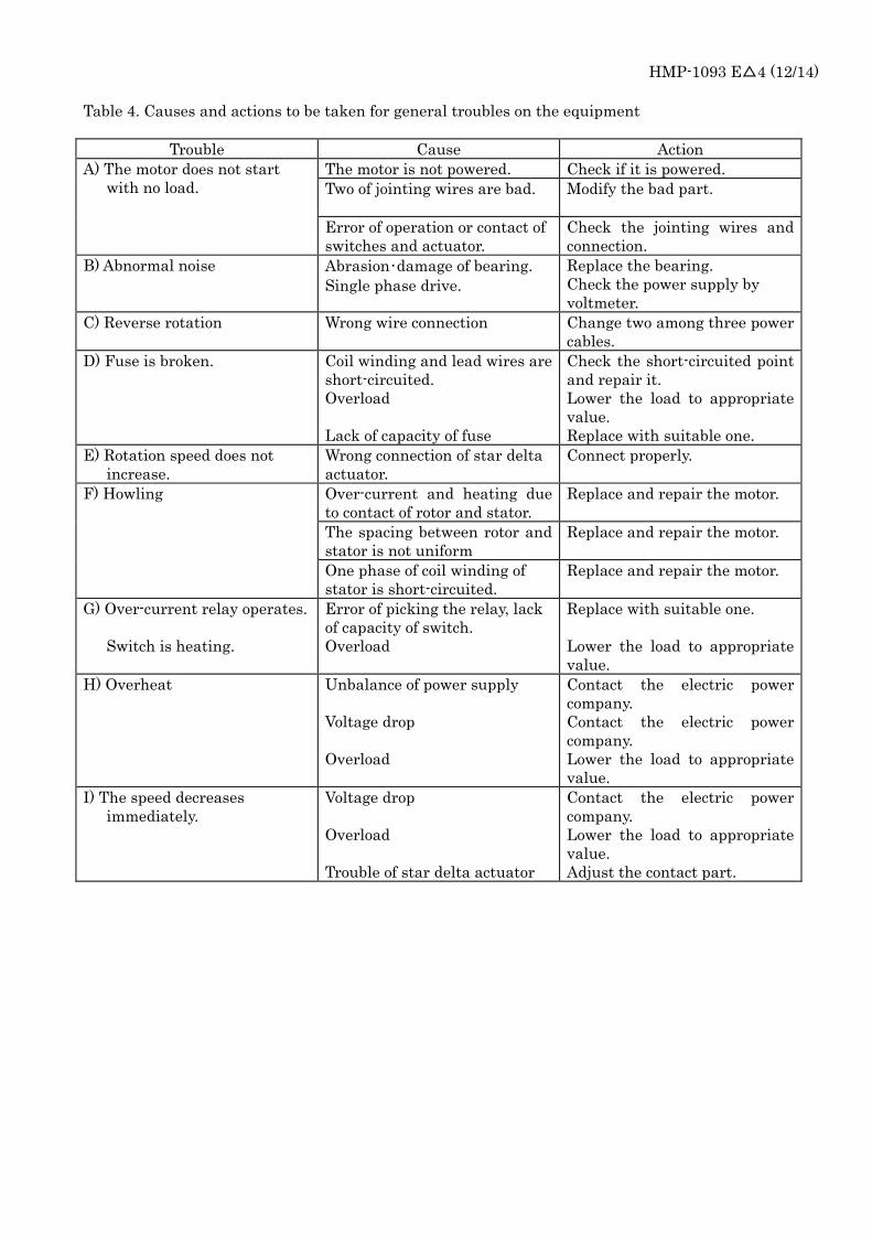
Table 4. Causes and actions to be taken for general troubles on the equipment
Trouble Cause Action
A) The motor does not start
with no load.
The motor is not powered. Check if it is powered.
Two of jointing wires are bad. Modify the bad part.
Error of operation or contact of
switches and actuator.
Check the jointing wires and
connection.
B) Abnormal noise Abrasion・damage of bearing.
Single phase drive.
Replace the bearing.
Check the power supply by
voltmeter.
C) Reverse rotation Wrong wire connection Change two among three power
cables.
D) Fuse is broken. Coil winding and lead wires are
short-circuited.
Overload
Lack of capacity of fuse
Check the short-circuited point
and repair it.
Lower the load to appropriate
value.
Replace with suitable one.
E) Rotation speed does not
increase.
Wrong connection of star delta
actuator.
Connect properly.
F) Howling Over-current and heating due
to contact of rotor and stator.
Replace and repair the motor.
The spacing between rotor and
stator is not uniform
Replace and repair the motor.
One phase of coil winding of
stator is short-circuited.
Replace and repair the motor.
G) Over-current relay operates.
Switch is heating.
Error of picking the relay, lack
of capacity of switch.
Overload
Replace with suitable one.
Lower the load to appropriate
value.
H) Overheat Unbalance of power supply
Voltage drop
Overload
Contact the electric power
company.
Contact the electric power
company.
Lower the load to appropriate
value.
I) The speed decreases
immediately.
Voltage drop
Overload
Trouble of star delta actuator
Contact the electric power
company.
Lower the load to appropriate
value.
Adjust the contact part.
HMP-1093 E△4 (13/14)
Delivery Rc 3/4
Rc 1
1/4
Relief return Rc 1/2
Leak port of shaft seal Rc 3/8
Suction
Fig4.Pump/Motor assembly
Rc 3/4
5 2 Spring washer
4 2 Bolt
3 1 Relief valve
2 1 Pump
1 1 Motor
No. Q’ty Description
Fig5. Pump/Motor assembly
with pipe/flange(option) (They are not installed on a pump.)
Suction : PS-L , PS-S Relief return : PR-L , PR-S Flange : EF-6 (This option dose not include a pressure gauge.)
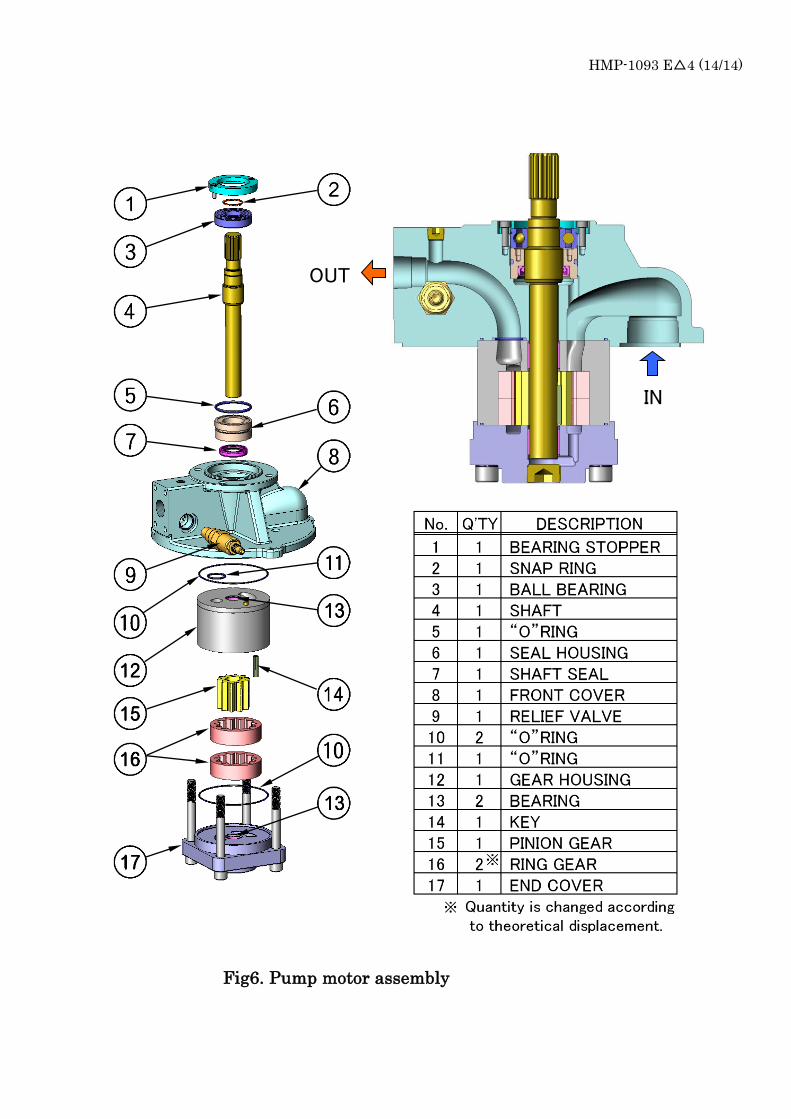
HMP-1093 E△4 (14/14)
IN
OUT
Fig6. Pump motor assembly