Embed Size (px)
Citation preview

Operation Manual
GSM modem iRZ TU41

2
Table of Contents
1. Introduction ............................................................................................................................. 4
1.1. About this Document ............................................................................................................................ 4
1.2. Service Information ............................................................................................................................... 4
1.3. Safety Precautions ............................................................................................................................... 4
2. Overview .................................................................................................................................. 5
2.1. Purpose ................................................................................................................................................ 5
2.2. Package Contents ................................................................................................................................ 5
2.3. Specifications........................................................................................................................................ 5
2.4. Device View .......................................................................................................................................... 7
2.5. Interfaces .............................................................................................................................................. 9
2.5.1. Terminal Strip Connector .............................................................................................................. 9
2.5.2. DB9 connector (RS232) .............................................................................................................. 10
2.5.3. Mini USB Connector ................................................................................................................... 11
2.5.4. Microfit 4 Power Connector ........................................................................................................ 11
2.5.5. Microfit 10 connector................................................................................................................... 12
2.6. The Modem Status Indication ............................................................................................................. 14
2.6.1. Watchdog Timer .......................................................................................................................... 15
3. Functional Diagram and Operation Description ................................................................. 16
3.1. Functional Diagram ............................................................................................................................ 16
4. Operation Description ........................................................................................................... 17
5. Connection and Configuration ............................................................................................. 18
5.1. Connection.......................................................................................................................................... 18
5.2. Control, Reset and Power Off ............................................................................................................. 18
5.3. Menu ................................................................................................................................................... 19
6. Creating, Installing and Removing Java Based Applications ............................................ 21
7. Using AT Commands to Operate the iRZ TU41 GSM Modem ............................................ 23
8. Emergencies .......................................................................................................................... 25
8.1. Emergency 1 (incorrect input power supply) ...................................................................................... 25
8.2. Alarm 2 (incorrect module power supply) ........................................................................................... 25
8.3. Emergency 3 (GSM module failed to run) .......................................................................................... 25
9. Support .................................................................................................................................. 26

3
List of Tables
Table 2.1 Terminal strip connector pin assignments ............................................................................................. 9
Table 2.2 DB9 connector pin assignments .......................................................................................................... 11
Table 2.3 Power connector pin assignments ....................................................................................................... 12
Table 2.4 Designation of MicroFit 10 connector's pins ........................................................................................ 13
Table 2.5 Operation mode indicator (green SYS LED) ........................................................................................ 14
Table 2.6 Fault condition indication (red LED SYS) ............................................................................................ 14
Table 2.7 SIM1 and SIM2 indication .................................................................................................................... 14
Table 2.8 Signal Strength Indicators .................................................................................................................... 15
Table 7.1 List of AT Commands to operate the iRZ TU41 GSM Modem ............................................................ 23
List of Figures
Fig. 2.1 Front panel ................................................................................................................................................ 7
Fig. 2.2 Back panel ................................................................................................................................................ 8
Fig. 2.3 Terminal Strip Connector .......................................................................................................................... 9
Fig. 2.4 DB9 connector ........................................................................................................................................ 10
Fig. 2.5 Mini USB Connector ................................................................................................................................ 11
Fig. 2.6 Power connector (Microfit 4) ................................................................................................................... 12
Fig. 2.7 Microfit 10 connector ............................................................................................................................... 12
Fig. 3.1 Functional diagram of TU41 GSM modem ............................................................................................. 16
Fig. 6.1 My Computer window in Windows 7 ....................................................................................................... 21
Fig. 6.2 Selecting the Required COM Port ........................................................................................................... 21

4
1. Introduction
1.1. About this Document
The operation manual is intended for skilled PC users and provides the description and operating
procedure of the iRZ TU41 GSM modem.
1.2. Service Information
Document version Issue Date
1.3 01/02/2016
Written by: P. Malikova Approved by: B. Makatrinskiy, D. Pavlov
1.3. Safety Precautions
Restrictions on the router use near other electronic devices:
Power off the modem in medical centres and keep it away from medical equipment (cardiac
pacemakers, hearing aids). Medical equipment may be susceptible to any form of radio
interference. In such areas the modem can transmit signals that could interfere with this
equipment.
Power off the modem in an aircraft. Take measures against accidental activation;
Power off the modem near gas stations, enterprises of chemical industry, in areas where
blasting operations are in progress. The modem can interfere with operation of technical
devices.
At close range the modem can interfere with television and radioreceiver operation.
To ensure safe operation, follow the recommendations:
Do not expose the modem to aggressive influences (high temperatures, corrosive chemicals,
dust, water, etc.).
Protect the modem from impacts, falls and excessive vibration.
Do not attempt to disassemble or modify the modem. Such actions will void the warranty.
Note: Use the device in compliance with the operating instructions. Damages caused by
improper use and storage of the device are not covered by the warranty.
Note! All wiring and electrical connection must be performed by a qualified electrician!

5
2. Overview
2.1. Purpose
The iRZ TU41 GSM modem is an industrial GSM modem designed for data and text messages
communication over cellular network. The built-in TCP/IP stack and open Java platform provides
easy integration of the modem into multiple M2M solutions: telemetry and telemechanics, wireless
automated data collection systems, vending machines, self-service terminals, remote monitoring,
control and signalling.
2.2. Package Contents
The iRZ TU41 GSM modem package includes:
iRZ TU41 modem;
original package.
2.3. Specifications
General characteristics:
Frequency bands:
900/1800 MHz for GSM/GPRS/EDGE;
900/2100 MHz for HSPA+/UMTS.
Output power:
33 dBm (Class 4) for EGSM900;
30 dBm (Class 1) for GSM1800;
27 dBm (Class E2) for GSM900 8-PSK;
26 dBm (Class E2) for GSM1800 8-PSK;
24 dBm (Class 3) for UMTS2100, WCDMA FDD BdI;
24 dBm (Class 3) for UMTS900, WCDMA FDD BdVIII.
Communication Standards:
MS Class В; USSD;
USSD;
SMS: MT, MO, Text and PDU.
Java™ Parameters:
Java™ profile IMP-NG & CLDC 1.1 HI;
Secure data transmission with HTTPS/SSL;

6
Multi-threading programming and multi-application execution;
6 MB RAM and 8 MB Flash File System.
Standards and data transmission rates:
HSPA+ download — 7,2 Mbps, upload — 5,7 Mbps;
UMTS PS download — 384 kbps, upload — 384 kbps;
UMTS CS download — 64 kbps, upload — 64 kbps;
EDGE Class 12, download — 236.8 kbps, upload — 236,8 kbps;
GPRS Class 12, download — 85,6 kbps, upload — 42,8 kbps.
Power Supply
power voltage from 7 to 40V;
current consumption:
at power supply voltage +12V – max 400 mA;
at power supply voltage +24V – max 200 mA.
GPIO 1-3 in the "input" mode:
resistance of the programmable pull-up to power voltage – 10 kΩ;
programmable pull-down resistor – 47 kΩ;
maximum "0" level voltage (low level) – 0.8 V
minimum "1" level voltage (high level) – 2.0 V
maximum allowable input voltage – 40 V.
GPIO 1-3 in the "output" mode:
output type – open collector to ground;
output resistance – 120 Ω;
maximum output current – 10 mA.
GPIO 4-7 in the "input" mode:
maximum "0" level voltage (low level) – 0.8 V
minimum "1" level voltage (high level) – 2.0 V
maximum allowable input voltage – 40 V.
GPIO 4-7 in the "output" mode:
output type – open collector to power voltage;
output resistance – max2 Ω;

7
5
3
maximum output current – 500 mA.
Interfaces and Connectors:
USB-mini connector – data cable connection, USB 2.0. interface;
DB9 connector (RS232 interface) – data cable connection;
SMA connector – 2G/3G antenna connection;
Microfit 4 connector – the modem power supply.
Microfit 10 connector – connection of data cable, 2 ADC, 7 GPIO.
Terminal connector – the modem power supply, data cable connection, RS485/RS422
interface, the +3.3V external interface power supply.
Physical Specifications
dimensions – max 90х86х34 mm;
weight: max 125 grams;
Operating temperature: -30°С to +60°C
Storage temperature: -40°C to +85°C
2.4. Device View
The TU41 modem is a compact-size device encased in a plastic housing. The device view is
given in Fig. 2.1 and Fig. 2.2.
Fig. 2.1 Front panel

8
The numbers in the figure illustrate:
1. SIM 1 tray – SIM 1 and SIM 2 tray – SIM 2;
2. SIM 1/ SIM 2 tray eject button;
3. Terminal connector – data cable connection, RS485/RS422 interface, the +3.3V external
interface power supply.
4. SMA antenna connector – connection of the GSM antenna.
Fig. 2.2 Back panel
The numbers in the figure illustrate:
5. DB9 connector (RS232)
6. USB-mini interface;
7. MicroFit 4 power connector;
8. Microfit 10 connector – GPIO pins (7 digital inputs/outputs and 2 analog inputs (ADC)).

9
- +
1 2
3 4 5
8
2.5. Interfaces
2.5.1. Terminal Strip Connector
Terminal strip connector is used for connection to a control device, RS485 serial communications
and power connection. The modem is controlled via AT commands (see the command description on
the module).
Factory settings: speed auto bit/s, data bit – 8, parity – no, stop bit – 1.
The view of the terminal strip connector is shown in Fig. 2.3.
Fig. 2.3 Terminal Strip Connector
Table 2.1 Terminal strip connector pin assignments
Pin Signal Direction Function
6 OUT 3.3 V Output Power supply for external device interface
7 GND Ground Connected to the negative terminal of the power supply
8 Vcc Positive terminal of constant power supply voltage. Protected by a fuse and overvoltage (when applying voltage to input of over 40V) and reverse polarity protection circuit
When using RS422 interface
1 A Modem – device Receive Tx+
2 B Modem – device Receive Tx–
3 Sh Shielding
7 6
10
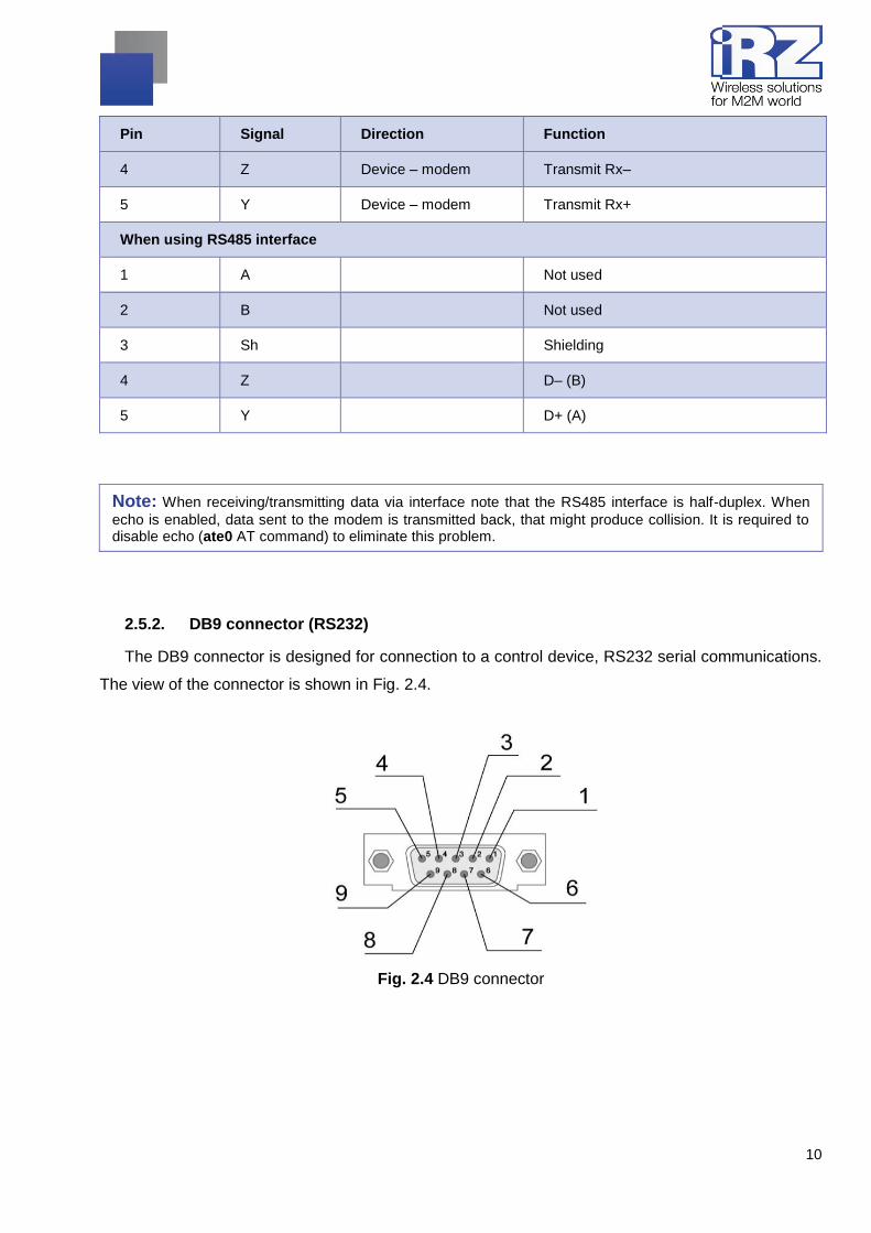
Pin Signal Direction Function
4 Z Device – modem Transmit Rx–
5 Y Device – modem Transmit Rx+
When using RS485 interface
1 A Not used
2 B Not used
3 Sh Shielding
4 Z D– (B)
5 Y D+ (A)
Note: When receiving/transmitting data via interface note that the RS485 interface is half-duplex. When
echo is enabled, data sent to the modem is transmitted back, that might produce collision. It is required to disable echo (ate0 AT command) to eliminate this problem.
2.5.2. DB9 connector (RS232)
The DB9 connector is designed for connection to a control device, RS232 serial communications.
The view of the connector is shown in Fig. 2.4.
Fig. 2.4 DB9 connector

11
Table 2.2 DB9 connector pin assignments
Pin Signal Direction Function
1 DCD Modem-PC Carrier Detect
2 RXD Modem-PC Receive Data
3 TXD PC-Modem Transmit Data
4 DTR PC-Modem Data Terminal Ready
5 GND Ground System Housing
6 Not used
7 RTS PC-Modem Request To Send
8 CTS Modem-PC Clear To Send
9 RI Modem-PC Ring Indicator
2.5.3. Mini USB Connector
Mini USB connector is used to connect the mode directly to a computer (USB 2.0). Mini USB
connector can be also used to supply power to the modem. The view of the connector is shown in
Fig. 2.5.
For operation of the modem via Mini USB, it is required to install the USB driver which can be
downloaded from the official website of the Radiofid Group of Companies (www.radiofid.ru) in section
"Support". After installation of the driver, several new devices are to be displayed in the Windows
Device Manager.
Cinterion EHx USB Modem in the Modems section;
several Cinterion EHx USB COM Port ports in the Ports section;
Cinterion EHx USB COM Port 4 – the port to set up the modem and display the menu
Fig. 2.5 Mini USB Connector
2.5.4. Microfit 4 Power Connector
Microfit 4 connector is used to connect power to the modem. The view of the connector is shown
in Fig. 2.6.

12
Fig. 2.6 Power connector (Microfit 4)
Table 2.3 Power connector pin assignments
Pin Signal Function
1 Vcc Positive terminal of constant power supply voltage. Protected by a fuse and overvoltage (when applying voltage to input of over 40V) and reverse polarity protection circuit
2 GND Negative terminal of power supply voltage
3 Not used
4 Not used
2.5.5. Microfit 10 connector
The Microfit 10 connector is used to connect a patch cable and GPIO pins: 2 analogue inputs
(ADC), 7 digital inputs/outputs, 4 of which are power ones (up to 0,5A, switching to the "+" power
source), and +3,3V output to supply external interfaces with power. The view of the connector is
shown in Fig. 2.7.
Fig. 2.7 Microfit 10 connector
10
9 8 7
6 5 4
3 2
1 2
3 4
1

13
Table 2.4 Designation of MicroFit 10 connector's pins
Pin Signal Function
1 ADC1 Analog-to-digital converter. Input circuit parameters:
Input resistance 21.5 kΩ;
Input voltage divider by 3,15.;
measurement range – from 0 to 10 V.
2 ADC2 Analog-to-digital converter.
Input circuit parameters:
Input resistance 21.5 kΩ;
Input voltage divider by 3,15;
measurement range – from 0 to 10 V.
3 GND Ground Connected to the negative terminal of the power supply
4 GPIO1 Configurable general-purpose output
5 GPIO2 Configurable general-purpose output
6 GPIO3 Configurable general-purpose output
7 GPIO4 (GPO) Power general-purpose output
8 GPIO5 (GPO) Power general-purpose output
9 GPIO6 (GPO) Power general-purpose output
10 GPIO7 (GPO) Power general-purpose output

14
2.6. The Modem Status Indication
The modem is fitted with LED indication for displaying the connection's status as well as signal
level.
When device is powered up, all LEDs lit for 1.5 sec.
Table 2.5 Operation mode indicator (green SYS LED)
Status display mode Schematic LED signals representation
Operating mode
Off The modem is turned off
500ms on / 500ms off The modem is not registered to the network
50ms on / 3990ms off ... The modem is registered on the network
50ms on / 1990ms off
... GPRS connection established / Data transmission in progress (GPRS)
50ms on / 990ms off ... Voice call, CSD
Table 2.6 Fault condition indication (red LED SYS)
Status display mode Schematic LED signals representation
Fault description
Continuously lit
Wrong input voltage
0,25 sec on / 0,25 sec off / 0,25 sec on / 1 sec off
GSM module failed to start
0.5 sec on / 0.5 sec off
Wrong module power
Table 2.7 SIM1 and SIM2 indication
Status display mode Schematic LED signals representation
Operating mode
SIM1 Green LED is continuously lit SIM1 is selected
SIM1 Red LED is continuously lit SIM1 tray is ejected.
SIM1 LED is off SIM1 tray inserted / SIM2 is
selected
SIM2 Green LED is continuously lit SIM 2 is selected
SIM2 Red LED is continuously lit SIM2 tray is ejected.

15
SIM2 LED is off SIM2 tray inserted / SIM2 is
selected
Table 2.8 Signal Strength Indicators
Status display mode Schematic LED signals representation
Operating mode
Green LED is continuously lit Good signal level (CSQ=23-31) 2G
0.25 sec on / 0.25 sec off Medium signal level (CSQ=16-22) 2G
0.25 sec on / 1.5 sec off Low signal level (CSQ=0-15) 2G
Blue LED is continuously lit Good signal level (CSQ=23-31) 3G
0.25 sec on / 0.25 sec off Medium signal level (CSQ=16-22) 3G
0.25 sec on / 1.5 sec off Low signal level (CSQ=0-15) 3G
2.6.1. Watchdog Timer
GSM modem is fitted with several types of watchdog timers.
Managing microcontroller-integrated watchdog timer. Checking MC's software for hang up
(Cannot be disabled);
Periodic check of GSM module (Java application) hang up by integrated Java program. Its
operation principle is as follows: Java sends a periodic command “at$java” and awaits a
response: “OK”. If the response is not received, GSM module is reset. Power supply is shut off
(by default, can be changed via at$rst=0; in this case modem is reset via modem's PIN without
power supply shutoff). Periodic check interval can be set for 1 minute to 255 minutes with 1
minute step. Interval can be set via AT command “at$control=ХХХ”, where XXX is time in
minutes (0-OFF); max value is 255.
Modem is reset unconditionally at the set intervals. This function is disabled by default.
Interval can be set for 1 to 255 hours with 1 hour step. Its operation principle is as follows: the
managing microcontroller resets the GSM module at set periods of time; module's power is
switched off. The function is controlled from the Menu.
16
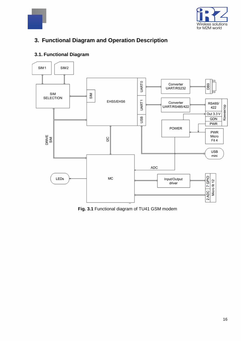
3. Functional Diagram and Operation Description
3.1. Functional Diagram
Fig. 3.1 Functional diagram of TU41 GSM modem

17
4. Operation Description
When connecting power supply to the modem, all of the LEDs lit for 1.5 sec (LED check). Then
the modem starts operating.
If one of the two SIM trays contains a SIM card, the modem operates with a said SIM card.
If both SIM trays are inserted and the modem is in operating mode – It operates with SIM1.
If both SIM trays are inserted and there is no network access from SIM1 for 3 minutes, the
modem switches to SIM2. If the connection could not be established for 3 minutes again, the modem
switches back to SIM1.
Switching from SIM1 and SIM2 is carried out via AT command at$sim (at$sim1 – working with
SIM1, at$sim2 – working with SIM2).
Modem can be powered from any of the 3 connectors: power connector, USB connector or
terminal connector.

18
5. Connection and Configuration
5.1. Connection
All installation operations are to be carried out by a qualified specialist familiar with the installation
guide.
Before supplying power, install the SIM card into the modem. SIM card installation and removing
is to be carried out only when the device is powered off. To install SIM card, follow the steps:
remove the SIM tray pressing the SIM tray eject button (Fig. 2.1);
insert a SIM card into the SIM card tray;
insert the SIM card tray into the modem;
insert SIM card tray into the SIM1 slot.
To reserve Internet-connection, repeat all steps with a SIM2 and put it in SIM2 tray.
Do not apply much force when inserting a SIM card.
Connect a GSM antenna and a switching cable (RS232/RS485/RS422). Connect power supply
via power connector, terminal connector or USB connector. After the power has been connected, the
modem will start. It will be indicated by all of the LEDs getting lit for 1.5 sec. If PIN code is switched
off, registration within network will occur automatically. As soon as the registration is complete the
modem switches to an operation mode.
Note: A GSM antenna, switching cables and a power supply unit are not included.
5.2. Control, Reset and Power Off
The modem is controlled using standard AT commands as well as a set of original commands
(see GSM module AT commands description). Additional information can be found on the websites
www.radiofid.ru and www.irz.net.
You can reboot the modem in the following ways:
Reboot after a set period of time (WD interval, switched off by default). Configured via Menu;
by AT command “AT+CFUN=1,1”;
by temporary powering off.
You can turn off the modem in the following ways:
by powering off;
by AT command “AT^SMSO”.
If modem was turned off with AT command, alarm function can be used to switch it back on
(ALARM mode).
19
Switching to power saving mode is done with AT command “AT+CFUN”. ALARM mode control is
carried out with AT command “AT+CALA”. For more detailed information, see description of AT
commands for GSM module.
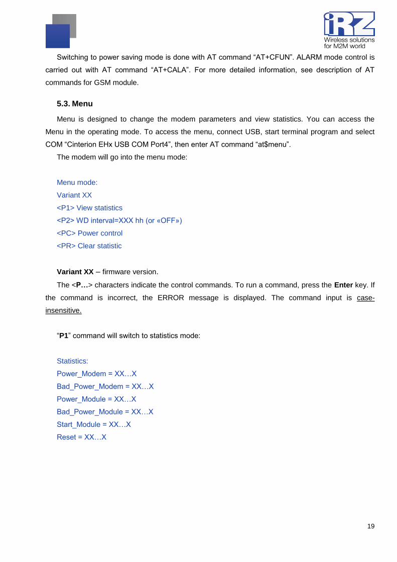
5.3. Menu
Menu is designed to change the modem parameters and view statistics. You can access the
Menu in the operating mode. To access the menu, connect USB, start terminal program and select
COM “Cinterion EHx USB COM Port4”, then enter AT command “at$menu”.
The modem will go into the menu mode:
Menu mode:
Variant XX
<P1> View statistics
<P2> WD interval=ХХХ hh (or «OFF»)
<PC> Power control
<PR> Clear statistic
Variant XX – firmware version.
The <P…> characters indicate the control commands. To run a command, press the Enter key. If
the command is incorrect, the ERROR message is displayed. The command input is case-
insensitive.
“P1” command will switch to statistics mode:
Statistics:
Power_Modem = XX…X
Bad_Power_Modem = XX…X
Power_Module = XX…X
Bad_Power_Module = XX…X
Start_Module = XX…X
Reset = XX…X

20
When using the modem, the following events are automatically saved.
Power_Modem – the number of the modem actuations;
Bad_Power_Modem – the number of power deviations of the modem;
Power_Module – the number of power supplies applied to the GSM module;
Bad_Power_Modem – the number of power deviations of the GSM module;
Start_Module – the number of successful starts of the GSM module;
Reset – the number of reboots.
After displaying statistics, the modem will switch to Main Menu
“P2” command will switch to WD mode:
WD interval, hour (0 – WD off, max – 255)
<Q> Quit
WD interval=
This sets the time interval for module restart. To change it, enter number from 0 to 255 and press
"Enter" key. Interval is set in hours. To disable this function enter 0. Please note that the modem will
be forced to restart after interval expiration. If entry is incorrect, "ERROR" message will be displayed
and you will be redirected to WD menu again. If entry is correct or after entering “Q” command, you
will be redirected to Main menu.
Entering the “PC” command allows reviewing the input voltage and the voltage of the module
(measurement precision 5%):
P0WER Uin=ХХ.Х Umd=Х.Х
After displaying data, the modem will switch to Main Menu
“PR” command will switch to statistics reset menu:
Clear statistic?
<YES> YES
<Q> Quit
Reset the accumulated statistics by <YES> command. If entry is incorrect, "ERROR" message
will be displayed and you will be redirected to WD menu again. If entry is correct or after entering
<Q> command, you will be redirected to Main menu.
Entering “M” command switches back to Main menu.
The exit from Menu mode occurs after when SIM tray is inserted.
21
6. Creating, Installing and Removing Java Based Applications
This modem is built on EHS5 module with integrated Java platform, which allows performing
numerous tasks. You can create, install and delete Java applications via special tool "Module
Exchange Suite" (MES) by Cinterion Company. This software can be found on our website
www.radiofid.ru. Alternatively you can order Software CD from our managers.
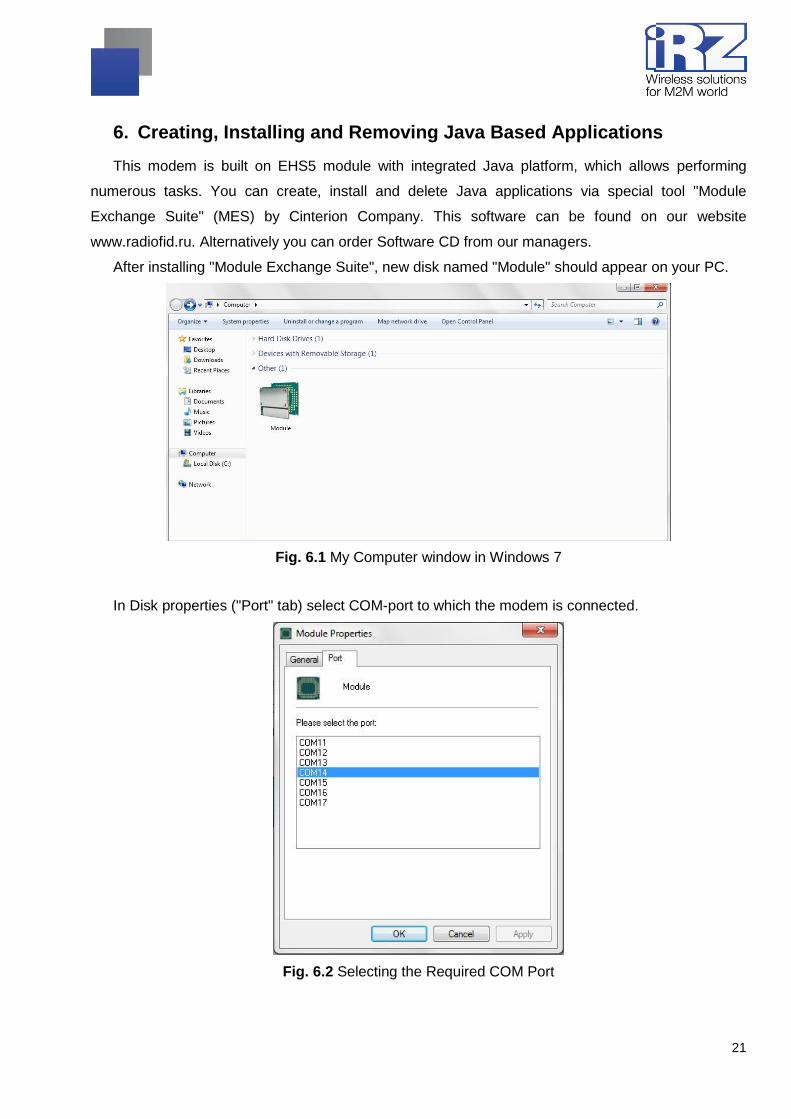
After installing "Module Exchange Suite", new disk named "Module" should appear on your PC.
Fig. 6.1 My Computer window in Windows 7
In Disk properties ("Port" tab) select COM-port to which the modem is connected.
Fig. 6.2 Selecting the Required COM Port

22
"Module Exchange Suite" writes and deletes files from "Module" disk. For example, to install Java
application, just copy program’s files to "Module" disk and send AT command
AT^SJAM=0,"a:/HelloUniverse.jad","" .
Java application's autostart is set using the following AT commands:
AT^SCFG="userware/autostart/delay","","100" (autostart initiates in 10 seconds after module
was switched on);
AT^SCFG="userware/autostart","","1" (autostart enabled).
AT^SJAM=0,"a:/HelloUniverse.jad","" – ( install an application into the module's memory)
Also you need to add the following lines into the .jad file:
Oracle-MIDlet-Autostart: n (numerical number of midlet at launch, its value range is 0...5 "0"
indicates that autostart is disabled)
Oracle-MIDlet-Restart: true (restart the midlet in case of incorrect termination).
Oracle-MIDlet-Restart-Count: m (figure representing number of times the application may be
restarted before restarting the module).
It is recommended to set autostart interval to ~10 seconds. It is especially important when testing
new Java applications, since it simplifies the procedure of autostart disabling. After Java application
autostart, port(s) may not react to AT commands.
For deleting Java application disable its autostart via AT^SJAM=2,"a:/HelloUniverse.jad","" AT
command. It requires a sufficient autostart interval set in advance, or having a port that responds to
AT commands available and not used by running Java applications. It is recommended to send this
AT command after 2-5 seconds after powering up the modem. If there is a port not used by running
Java applications, AT command may be sent at any moment. After AT command was successfully
sent, modem gives a reply: "OK". Now you should send command
AT^SJAM=3,"a:/HelloUniverse.jad","" – delete application. Note that .jar and .jad files will not be
deleted from internal memory – you can delete them manually via MES.
Deleting Java applications means deleting files on "Module" disk. Also, there is an option to
remotely update Java application – "Over The Air Provisioning" (OTAP). For more detailed
information, address documentation on Development Software CD.
23
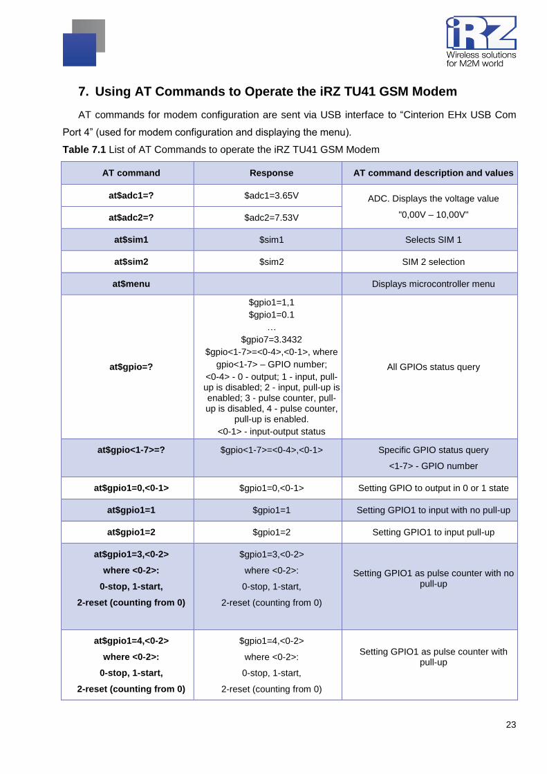
7. Using AT Commands to Operate the iRZ TU41 GSM Modem
AT commands for modem configuration are sent via USB interface to “Cinterion EHx USB Com
Port 4” (used for modem configuration and displaying the menu).
Table 7.1 List of AT Commands to operate the iRZ TU41 GSM Modem
AT command Response AT command description and values
at$adc1=? $adc1=3.65V ADC. Displays the voltage value
"0,00V – 10,00V" at$adc2=? $adc2=7.53V
at$sim1 $sim1 Selects SIM 1
at$sim2 $sim2 SIM 2 selection
at$menu Displays microcontroller menu
at$gpio=?
$gpio1=1,1
$gpio1=0.1
…
$gpio7=3.3432
$gpio<1-7>=<0-4>,<0-1>, where
gpio<1-7> – GPIO number;
<0-4> - 0 - output; 1 - input, pull-up is disabled; 2 - input, pull-up is enabled; 3 - pulse counter, pull-up is disabled, 4 - pulse counter,
pull-up is enabled.
<0-1> - input-output status
All GPIOs status query
at$gpio<1-7>=?
$gpio<1-7>=<0-4>,<0-1> Specific GPIO status query
<1-7> - GPIO number
at$gpio1=0,<0-1> $gpio1=0,<0-1> Setting GPIO to output in 0 or 1 state
at$gpio1=1 $gpio1=1 Setting GPIO1 to input with no pull-up
at$gpio1=2 $gpio1=2 Setting GPIO1 to input pull-up
at$gpio1=3,<0-2>
where <0-2>:
0-stop, 1-start,
2-reset (counting from 0)
$gpio1=3,<0-2>
where <0-2>:
0-stop, 1-start,
2-reset (counting from 0)
Setting GPIO1 as pulse counter with no pull-up
at$gpio1=4,<0-2>
where <0-2>:
0-stop, 1-start,
2-reset (counting from 0)
$gpio1=4,<0-2>
where <0-2>:
0-stop, 1-start,
2-reset (counting from 0)
Setting GPIO1 as pulse counter with pull-up

24
at$halfduplex $halfduplex Selecting RS485 as a COM port mode
(by default)
at$fullduplex $fullduplex Selecting RS422 as a COM port mode
at$rst=1 $rst=1 Going to Reset mode, which initiates
modem reset with switching off GSM module's power supply (by default)
at$rst=0 $rst=0 Going to Reset mode, which initiates
modem reset without switching off GSM module's power supply (by default)
at$rst=? $rst=X
Х-(1 or 0) Requesting details on RESET type
at$control=ХХХ
$control=ХХX where ХХХ – time in minutes (0 – OFF, maximal time – 255
min)
Set the interval for modem hang up check. If hang up is detected, the reset
is initiated.
at$control=?
$control=ХХX where ХХХ – time in minutes (0 – OFF, maximal time – 255
min)
Request information on modem hang up check interval.
at$cclk? $cclk=2012/01/01,12:00:01 Requesting set modem time
at$cclk=2014/01/01,12:00:01 $cclk=2014/01/01,12:00:01 Setting modem time.

25
8. Emergencies
To facilitate the use of the modem, tracking and display of emergencies are provided.
8.1. Emergency 1 (incorrect input power supply)
Emergency 1 occurs when the input power supply deviates from the permissible value. The
modem stops operating and switches off GSM module power supply. Red LED signal is continuously
lit to indicate emergency. The recovery is possible only when the input power supply is re-
established.
8.2. Alarm 2 (incorrect module power supply)
Emergency 2 occurs when GSM module's' power supply deviates from the permissible value. The
modem stops operating and switches off GSM module power supply. A red LED signals that the
emergency has occurred (0.5s on / 0.5s off). The recovery is possible only if the module power
supply is re-established within 10 seconds after the emergency occurred. If within 10 seconds the
module power supply remains incorrect (with a correct input power supply), the modem goes into the
waiting mode meaning that the modem’s power supply is turned off, the emergency indication is
preserved. The waiting mode can be terminated only after the power is completely disconnected.
In case of repeated emergency, the modem should be serviced.
8.3. Emergency 3 (GSM module failed to run)
Emergency 3 occurs if the GSM module does not turn on or is absent. A red LED signal (0.25s on
/ 0.25s off / 0.25s on / 1s off) turns on after the modem precisely detects the emergency situation
(~15 sec). The recovery is possible only after a successful launch of the GSM module. After 10
unsuccessful attempts to launch the module, the modem goes into the waiting mode. The modem’s
power supply is turned off, the emergency indication is preserved. The waiting mode can be
terminated only after the power is completely disconnected.
In case of repeated emergency, the modem should be serviced.

26
9. Support
To get updated documents and software updates, please use the following contacts:
St. Petersburg
The company’s website: www.radiofid.ru
Phone number in St. Petersburg: +7 (812) 318 18 19
E-mail: [email protected]
Moscow
The company’s website: www.digitalangel.ru
Phone number in Moscow: +7 (495) 974 74 22
E-mail: [email protected]
Our specialists are always ready to answer your questions, assist in installation, configuration and
resolve difficulties with using the equipment.


![IRZ artificial lift solutions [version 1.4 july 2016]](https://img.pdfslide.net/doc/110x75/5878547d1a28ab68198b6f2b/irz-artificial-lift-solutions-version-14-july-2016.jpg)