Embed Size (px)
Citation preview
© 2017 ZOOM CORPORATIONCopying or reprinting this manual in part or in
whole without permission is prohibited.
Operation Manual
C
on
tents
02
ContentsContents ...........................................................................................................02Usage and Safety Precautions ........................................................................04Introduction ......................................................................................................05Names of parts .................................................................................................06Connecting mics/other devices to Inputs 1–8................................................08LCD display ...................................................................................................... 11
PreparationsSupplying power .............................................................................................14Loading an SD card .........................................................................................16Turning the power on and off .........................................................................17Setting the date and time (Date/Time (RTC)).................................................18Disabling the Automatic Power Saving function (Auto Power Off) .............20Setting the power supply used (Power Source) ............................................21
RecordingRecording process ...........................................................................................23Enabling recording on SD cards and setting file formats ............................24Selecting inputs and adjusting levels ............................................................26Recording .........................................................................................................28Setting the sampling rate (Sample Rate) .......................................................29Setting WAV file bit depth (WAV Bit Depth) ...................................................30Setting MP3 file bit rate (MP3 Bit Rate)..........................................................31Simultaneously recording tracks at different levels (Dual Channel Rec) ....32Capturing audio before recording starts (Pre Rec) .......................................34Maximum file size (File Max Size) ..................................................................35Showing total recording times for long recordings (Time Counter) ...........36Folder and file structure ..................................................................................37Moving the previously recorded take to the FALSE TAKE folder .................39
Recording take settingsChanging the note for the next take recorded (Note) ...................................40Setting how recorded scenes are named and numbered ............................42Setting the take reset condition and numbering format ..............................46Changing the track name of the next take recorded (Track Name) .............48
PlaybackPlaying recordings ...........................................................................................50Mixing takes .....................................................................................................51Monitoring the playback signals of specific tracks during playback ...........52Changing the playback mode (Play Mode) ....................................................53
Take and folder operationsTake and folder operations (FINDER) .............................................................54Information (metadata) stored in files ..........................................................61Checking and editing take metadata ..............................................................62Writing sound reports (Create Sound Report)...............................................70
Input settingsInput and output signal flow...........................................................................73Adjusting the input signal monitoring balance.............................................74Quickly setting fader/pan with input trim knobs (Trim Knob Option) .........75Adjusting the L/R track volume.......................................................................77Monitoring the input signals of specific tracks (PFL/SOLO) .........................78Setting the monitoring volume on the PFL screen (PFL Mode) ...................79Cutting low-frequency noise (HPF) ................................................................80Input limiter ......................................................................................................81Inverting the input phase (Phase Invert) ........................................................86Changing the phantom power settings (Phantom) ......................................87Changing the plugin power setting (Plugin Power) ......................................90Delaying input signals (Input Delay) ..............................................................91Converting mid-side input to ordinary stereo (Stereo Link Mode)..............92Adjusting the input levels of multiple tracks simultaneously (Trim Link) ...94Adjusting the side level of a mid-side mic capsule (Side Mic Level) ..........95

C
on
tents
03
F8 Multi Track Field Recorder
Output settingsSetting signals sent to headphones (Headphone Routing) ..........................96Outputting alerts through headphones (Alert Tone Level) ...........................99Disabling outputs (Output On/Off) ...............................................................100Setting the standard output level (Output Level) ........................................101Setting output levels .....................................................................................102Delaying output signals (Output Delay).......................................................103Output Limiter ................................................................................................104Selecting signals sent to the main outputs (MAIN OUT Routing) .............108Selecting signals sent to the sub outputs (SUB OUT Routing) .................109
TimecodeTimecode overview ....................................................................................... 110Setting timecode functions .......................................................................... 112Setting automatic timecode recording delay (Auto Rec Delay Time) ........ 119Setting how timecode is initialized at startup (Start Timecode).................120
Slate mic/slate tone Slate mic and slate tone overview ...............................................................121Recording with the slate mic (Slate Mic) .....................................................122Recording a slate tone (Slate Tone) ..............................................................125
Using USB functionsExchanging data with a computer (SD Card Reader) .................................129Using as an audio interface (Audio Interface) .............................................130Audio interface block diagrams ....................................................................132Audio interface settings ................................................................................134
Using an Using an as a controller (Connect) ...................................................136Setting the type of keyboard connected to the (Keyboard Type) ...137Setting user keys for the (User Key).................................................138Setting the power supply used by the (Power Source) ..................139Setting the LED brightness (LED Brightness) ..................................140Updating the firmware ......................................................................141
Various settingsSetting how timecode is shown (Home Timecode Display Size) ...............143Setting level meter appearance (Level Meter) ............................................144Setting the LED brightness (LED Brightness) ..............................................149Making display settings (LCD) ......................................................................150Adding marks when pausing (PLAY Key Option) ........................................152Setting the keys held (Key Hold Target) .......................................................154
Other functionsChecking SD card information (Information) ..............................................155Testing SD card performance (Performance Test) .......................................156Formatting SD cards (Format) ......................................................................159
Checking the Shortcut List ...............................................................160Backing up and loading settings (Backup/Load Settings) .............161Restoring default setting values (Factory Reset) .........................................163Checking the firmware version (Firmware Version) ....................................164Updating the firmware ..................................................................................165
AppendicesTroubleshooting .............................................................................................166Detailed product diagrams ...........................................................................167Metadata list ..................................................................................................169List of shortcuts .............................................................................................173Specifications .................................................................................................175
U
sage an
d S
afety Precautio
ns
04
Usage and Safety Precautions
Safety Precautions
In this operation manual, symbols are used to highlight warnings and cautions that you must read to prevent accidents. The meanings of these symbols are as follows.
Something that could cause serious injury or death
Something that could cause injury or damage to the equipment
Other symbols used
An action that is mandatory
An action that is prohibited
Warning
Operation using an AC adapter Never use any AC adapter other than a
ZOOM AD-19.
Operation with external DC power supply Use a 9V–16V external DC power supply. Carefully study the warning indications of
the external DC power supply before use.
Operation with batteries Use 8 commercially-available 1.5V AA bat-
teries (alkaline dry cell batteries, nickel metal hydride batteries or lithium dry cell batteries).
Carefully study the warning indications of the batteries before use.
Always keep the battery cover closed during use.
Alterations Do not open the case or modify the prod-
uct.
Caution
Product handling Do not drop, bump or apply excessive
force to the unit. Be careful not to allow foreign objects or
liquids to enter the unit.
Operating environment Do not use in extremely high or low tem-
peratures. Do not use near heaters, stoves and other
heat sources. Do not use in very high humidity or where
it could be splashed by water. Do not use in places with frequent vibra-
tions. Do not use in places with much dust or
sand.
AC adapter handling When disconnecting the power plug from
an outlet, always pull on the plug itself. Disconnect the power plug from the outlet
when the unit will not be used for extended periods and whenever there is lightning.
Battery handling Install batteries with the correct +/− orien-
tations. Use the specified batteries. Do not use
new and old batteries together. Do not use batteries of different brands or types together.
Remove the batteries when the unit will not be used for extended periods. If a leak occurs, thoroughly wipe the bat-tery case and battery terminals to remove the leaked fluid.
Danger of explosion if battery is incorrectly replaced. Replace only with the same or equivalent type.
A warning that batteries (battery pack or batteries installed) shall not be exposed to excessive heat such as sunshine, fire or the like.
Mic handling Always turn the power switch OFF before
connecting a mic. Do not apply unneces-sary force when connecting a mic.
Attach the protective cap when no mic is connected for extended periods.
Connection cables and input/output jacks Always turn the power OFF for all equip-
ment before connecting any cables. Always disconnect all connection cables
and the AC adapter before moving the unit.
Volume Do not use at a loud volume for extended
periods.
Usage Precautions
Interference with other electrical equipmentIn consideration of safety, the has been designed to minimize its emission of electro-magnetic waves and to suppress interference from external electromagnetic waves. How-ever, equipment that is very susceptible to interference or that emits powerful electro-magnetic waves could result in interference if placed nearby. If this occurs, place the and the other device farther apart.With any type of electronic device that uses digital control, including the , electro-magnetic interference could cause malfunc-tion, corrupt or destroy data and result in other unexpected trouble. Always use caution.
CleaningUse a soft cloth to clean the exterior of the unit if it becomes dirty. If necessary, use a damp cloth that has been wrung out well to wipe it.Never use abrasive cleansers, wax or solvents such as alcohol, benzene or paint thinner.
Breakdown and malfunctionIf the unit becomes broken or malfunctions, immediately disconnect the AC adapter or DC power supply, turn the power off and discon-nect other cables. Contact the store where you bought the unit or ZOOM service center with the following information: product model, serial number and specific symptoms of break-
down or malfunction, along with your name, address and telephone number.
Copyrights◎ Windows® and Windows® 7 are trademarks or registered trademarks of Microsoft® Corpo-ration.◎ Macintosh, Mac OS and iPad are trademarks or registered trademarks of Apple Inc.◎ The SD, SDHC and SDXC logos are trade-marks. MPEG Layer-3 audio compression tech-nology is licensed from Fraunhofer IIS and Sis-vel S.p.A.◎ Bluetooth and the Bluetooth logo are regis-tered trademarks of Bluetooth SIG, Inc. and are used under license by ZOOM CORPORATION.◎ Other product names, registered trademarks and company names in this document are the property of their respective companies.
Note: All trademarks and registered trade-marks in this document are for identifi-cation purposes only and are not intended to infringe on the copyrights of their respective owners.
Recording from copyrighted sources, including CDs, records, tapes, live performances, video works and broadcasts, without permission of the copyright holder for any purpose other than personal use is prohibited by law.ZOOM CORPORATION will not assume any responsibility related to infringements of copy-rights.
Note about the Auto Power Off functionThe power will automatically turn off if unused for 10 hours. If you want the power to instead remain on, see "Disabling the Automatic Power Saving function" on P.20 and turn the function off.
In
trod
uctio
n
05
F8 Multi Track Field Recorder
Introduction
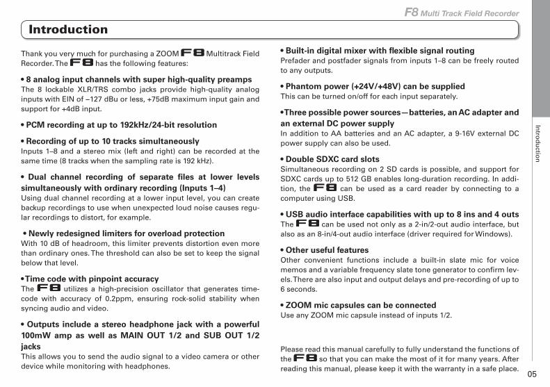
Thank you very much for purchasing a ZOOM Multitrack Field Recorder. The has the following features:
• 8 analog input channels with super high-quality preampsThe 8 lockable XLR/TRS combo jacks provide high-quality analog inputs with EIN of −127 dBu or less, +75dB maximum input gain and support for +4dB input.
• PCM recording at up to 192kHz/24-bit resolution
• Recording of up to 10 tracks simultaneouslyInputs 1–8 and a stereo mix (left and right) can be recorded at the same time (8 tracks when the sampling rate is 192 kHz).
• Dual channel recording of separate files at lower levels simultaneously with ordinary recording (Inputs 1–4)Using dual channel recording at a lower input level, you can create backup recordings to use when unexpected loud noise causes regu-lar recordings to distort, for example.
• Newly redesigned limiters for overload protectionWith 10 dB of headroom, this limiter prevents distortion even more than ordinary ones. The threshold can also be set to keep the signal below that level.
• Time code with pinpoint accuracyThe utilizes a high-precision oscillator that generates time-code with accuracy of 0.2ppm, ensuring rock-solid stability when syncing audio and video.
• Outputs include a stereo headphone jack with a powerful 100mW amp as well as MAIN OUT 1/2 and SUB OUT 1/2 jacksThis allows you to send the audio signal to a video camera or other device while monitoring with headphones.
• Built-in digital mixer with flexible signal routingPrefader and postfader signals from inputs 1–8 can be freely routed to any outputs.
• Phantom power (+24V/+48V) can be suppliedThis can be turned on/off for each input separately.
• Three possible power sources—batteries, an AC adapter and an external DC power supplyIn addition to AA batteries and an AC adapter, a 9-16V external DC power supply can also be used.
• Double SDXC card slotsSimultaneous recording on 2 SD cards is possible, and support for SDXC cards up to 512 GB enables long-duration recording. In addi-tion, the can be used as a card reader by connecting to a computer using USB.
• USB audio interface capabilities with up to 8 ins and 4 outsThe can be used not only as a 2-in/2-out audio interface, but also as an 8-in/4-out audio interface (driver required for Windows).
• Other useful featuresOther convenient functions include a built-in slate mic for voice memos and a variable frequency slate tone generator to confirm lev-els. There are also input and output delays and pre-recording of up to 6 seconds.
• ZOOM mic capsules can be connectedUse any ZOOM mic capsule instead of inputs 1/2.
Please read this manual carefully to fully understand the functions of the so that you can make the most of it for many years. After reading this manual, please keep it with the warranty in a safe place.
N
ames o
f parts
06
Back
Front
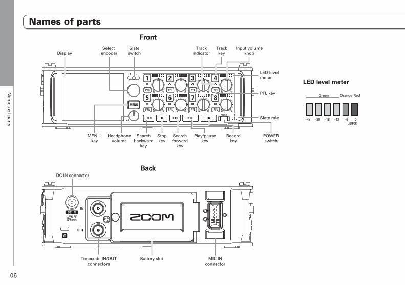
DisplaySelect
encoderSlate
switch
MENU key
Headphonevolume
Searchbackward
key
MIC INconnector
Battery slotTimecode IN/OUTconnectors
DC IN connector
Searchforward
key
Play/pausekey
Recordkey
POWERswitch
Stopkey
Trackkey
Trackindicator
Input volumeknob
LED level meter
Slate mic
PFL key
LED level meter
−48
Green Orange Red
−30 −18 −12 −6 0(dBFS)
Names of parts
N
ames o
f parts
07
F8 Multi Track Field Recorder
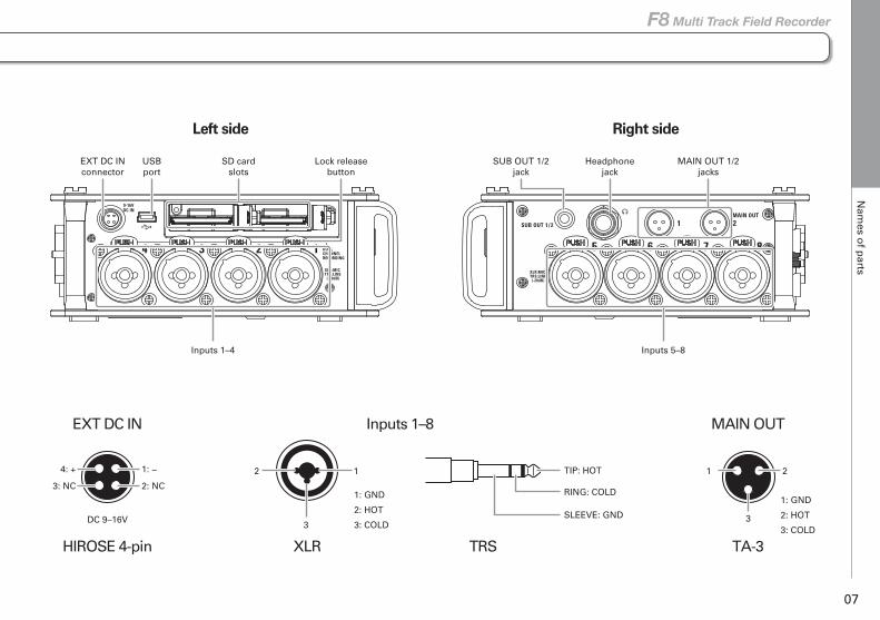
Left side
Inputs 1–8EXT DC IN MAIN OUT
XLR TA-3TRS
Right side
1: GND
2: HOT
3: COLD
1: GND
2: HOT
3: COLDDC 9–16V
HIROSE 4-pin
TIP: HOT
RING: COLD
SLEEVE: GND
EXT DC INconnector
SUB OUT 1/2jack
Headphonejack
USBport
SD cardslots
Inputs 5–8Inputs 1–4
MAIN OUT 1/2jacks
Lock releasebutton
121: −4: +
2: NC3: NC
21
33
Names of parts
C
on
nectin
g m
ics/oth
er devices to
Inp
uts 1–8
08
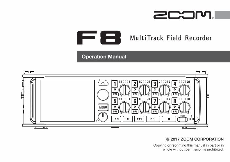
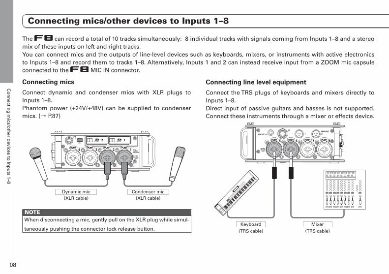
Connecting mics
Connect dynamic and condenser mics with XLR plugs to Inputs 1–8.Phantom power (+24V/+48V) can be supplied to condenser mics. (→ P.87)
Dynamic mic(XLR cable)
Condenser mic(XLR cable)
NOTEWhen disconnecting a mic, gently pull on the XLR plug while simul-
taneously pushing the connector lock release button.
Connecting line level equipment
Connect the TRS plugs of keyboards and mixers directly to Inputs 1–8.Direct input of passive guitars and basses is not supported. Connect these instruments through a mixer or effects device.
(TRS cable)Keyboard
(TRS cable)Mixer
The can record a total of 10 tracks simultaneously: 8 individual tracks with signals coming from Inputs 1–8 and a stereo mix of these inputs on left and right tracks.You can connect mics and the outputs of line-level devices such as keyboards, mixers, or instruments with active electronics to Inputs 1–8 and record them to tracks 1–8. Alternatively, Inputs 1 and 2 can instead receive input from a ZOOM mic capsule connected to the MIC IN connector.
Connecting mics/other devices to Inputs 1–8
Connecting mics/other devices to Inputs 1–8
C
on
nectin
g m
ics/oth
er devices to
Inp
uts 1–8
09
F8 Multi Track Field Recorder
Connecting mic capsules
A ZOOM mic capsule can be connected to the MIC IN connec-tor on the back of the .
NOTE• The mic capsule input is assigned to tracks 1/2.
• When a mic capsule is connected, Inputs 1/2 cannot be used.
Connecting and disconnecting mic capsules
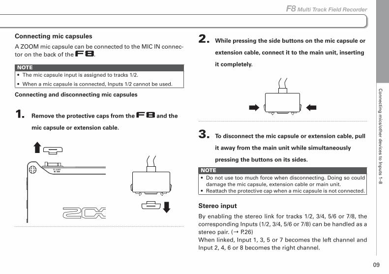
1. Remove the protective caps from the and the
mic capsule or extension cable.
2. While pressing the side buttons on the mic capsule or
extension cable, connect it to the main unit, inserting
it completely.
3. To disconnect the mic capsule or extension cable, pull
it away from the main unit while simultaneously
pressing the buttons on its sides.
NOTE• Do not use too much force when disconnecting. Doing so could
damage the mic capsule, extension cable or main unit.• Reattach the protective cap when a mic capsule is not connected.
Stereo input
By enabling the stereo link for tracks 1/2, 3/4, 5/6 or 7/8, the corresponding Inputs (1/2, 3/4, 5/6 or 7/8) can be handled as a stereo pair. (→ P.26)When linked, Input 1, 3, 5 or 7 becomes the left channel and Input 2, 4, 6 or 8 becomes the right channel.
Connecting mics/other devices to Inputs 1–8
C
on
nectin
g m
ics/oth
er devices to
Inp
uts 1–8
10
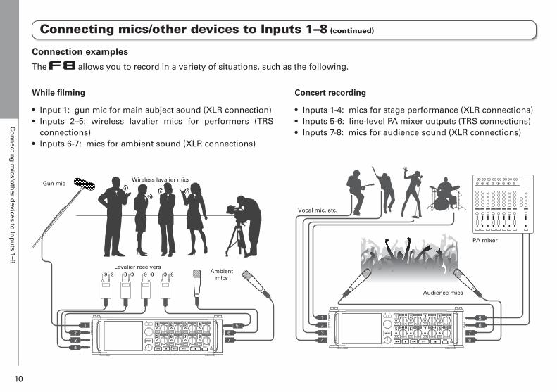
Concert recording
• Inputs 1-4: mics for stage performance (XLR connections)• Inputs 5-6: line-level PA mixer outputs (TRS connections)• Inputs 7-8: mics for audience sound (XLR connections)
PA mixer
Audience mics
Vocal mic, etc.
2
3
4
1
6
7
5
8
While filming
• Input 1: gun mic for main subject sound (XLR connection)• Inputs 2–5: wireless lavalier mics for performers (TRS
connections)• Inputs 6-7: mics for ambient sound (XLR connections)
Ambientmics
Wireless lavalier micsGun mic
Lavalier receivers
2
3
4
1
6
7
5
Connection examples
The allows you to record in a variety of situations, such as the following.
Connecting mics/other devices to Inputs 1–8 (continued)
LC
D d
isplay
11
F8 Multi Track Field Recorder
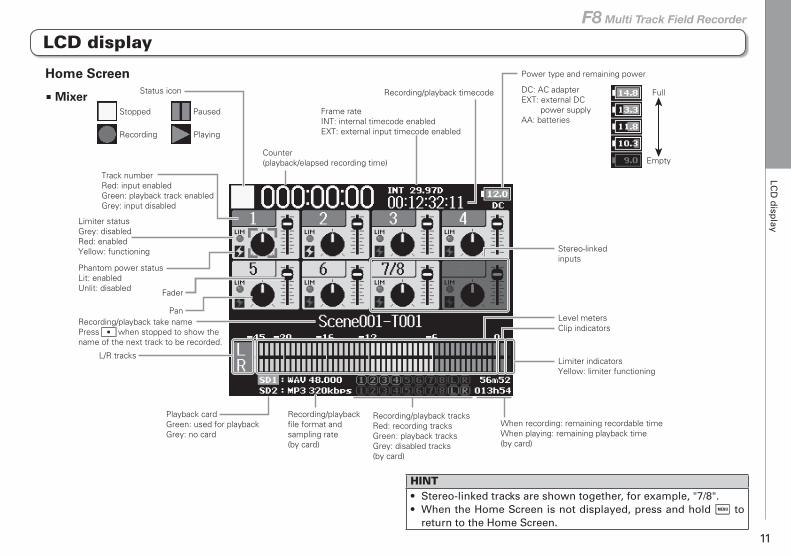
Recording/playbackfile format andsampling rate(by card)
When recording: remaining recordable timeWhen playing: remaining playback time(by card)
L/R tracks
Fader
PanRecording/playback take namePress when stopped to show thename of the next track to be recorded.
Track numberRed: input enabledGreen: playback track enabledGrey: input disabled
Recording/playback tracksRed: recording tracksGreen: playback tracksGrey: disabled tracks(by card)
Playback cardGreen: used for playbackGrey: no card
Stopped
Status icon
Recording
Counter(playback/elapsed recording time)
Frame rateINT: internal timecode enabledEXT: external input timecode enabled
Recording/playback timecode
Power type and remaining power
DC: AC adapterEXT: external DC power supplyAA: batteries
Full
Empty
Level meters
Stereo-linkedinputs
Clip indicators
Limiter indicatorsYellow: limiter functioning
Paused
Playing
Limiter statusGrey: disabledRed: enabledYellow: functioning
Phantom power status Lit: enabledUnlit: disabled
HINT• Stereo-linked tracks are shown together, for example, "7/8".• When the Home Screen is not displayed, press and hold to
return to the Home Screen.
Home Screen
■ Mixer
LCD display
LC
D d
isplay
12
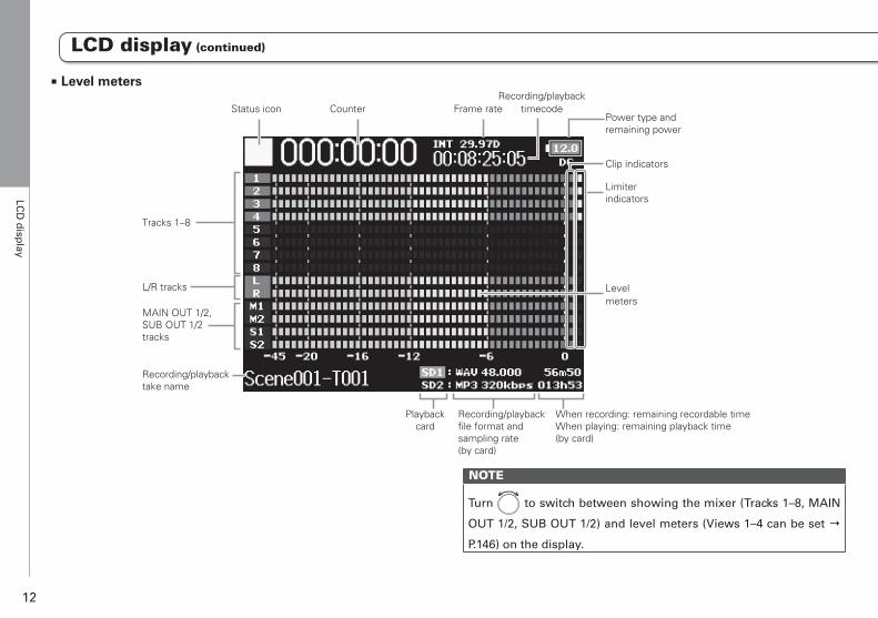
LCD display (continued)
Power type and remaining power
Limiter indicators
Tracks 1–8
MAIN OUT 1/2,SUB OUT 1/2tracks
L/R tracks Levelmeters
Status icon Counter Frame rateRecording/playback
timecode
Recording/playbacktake name
Playbackcard
Recording/playbackfile format andsampling rate(by card)
When recording: remaining recordable timeWhen playing: remaining playback time(by card)
Clip indicators
■ Level meters
NOTE
Turn to switch between showing the mixer (Tracks 1–8, MAIN
OUT 1/2, SUB OUT 1/2) and level meters (Views 1–4 can be set →
P.146) on the display.
LC
D d
isplay
13
F8 Multi Track Field Recorder
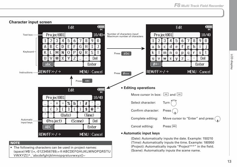
Character input screen
MENU::
abc
#+=
Number of characters input/Maximum number of characters
Press
Press
ABCPress
Keyboard
Instructions
Automaticinput keys
Text box
■ Editing operations
Move cursor in box: and
Select character: Turn
Confirm character: Press
Complete editing: Move cursor to “Enter” and press
Cancel editing: Press
■ Automatic input keys(Date): Automatically inputs the date. Example: 150210(Time): Automatically inputs the time. Example: 180950(Project): Automatically inputs “Project***” in the field. (Scene): Automatically inputs the scene name.
NOTE• The following characters can be used in project names:
(space) ! # $ ' ( ) + , - 0 1 2 3 4 5 6 7 8 9 ; = @ A B C D E F G H I J K L M N O P Q R S T U V W X Y Z [ ] ̂ _ ̀ a b c d e f g h i j k l m n o p q r s t u v w x y z { } ~
Preparatio
ns
Su
pp
lying
po
wer
14
Preparations
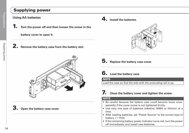
Using AA batteries
1. Turn the power off and then loosen the screw in the
battery cover to open it.
2. Remove the battery case from the battery slot.
3. Open the battery case cover.
4. Install the batteries.
+
-
-
+
+
-
-
+
+-
+
+
-
-
5. Replace the battery case cover.
6. Load the battery case.
NOTELoad the case so that the side with the protruding rail is up.
7. Close the battery cover and tighten the screw.
NOTE• Be careful because the battery case could become loose unex-
pectedly if the cover screw is not tightened firmly.• Use only one type of batteries (alkaline, NiMH or lithium) at a
time.• After loading batteries, set "Power Source" to the correct type of
battery. (→ P.22)• If the remaining battery power indicator turns red, turn the power
off immediately and install new batteries.
Supplying power
Preparatio
ns
Su
pp
lying
po
wer
15
F8 Multi Track Field Recorder
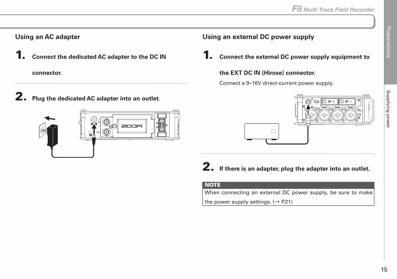
Using an external DC power supply
1. Connect the external DC power supply equipment to
the EXT DC IN (Hirose) connector.
Connect a 9–16V direct-current power supply.
2. If there is an adapter, plug the adapter into an outlet.
NOTEWhen connecting an external DC power supply, be sure to make
the power supply settings. (→ P.21)
Using an AC adapter
1. Connect the dedicated AC adapter to the DC IN
connector.
2. Plug the dedicated AC adapter into an outlet.
Preparatio
ns
Load
ing
an S
D card
16
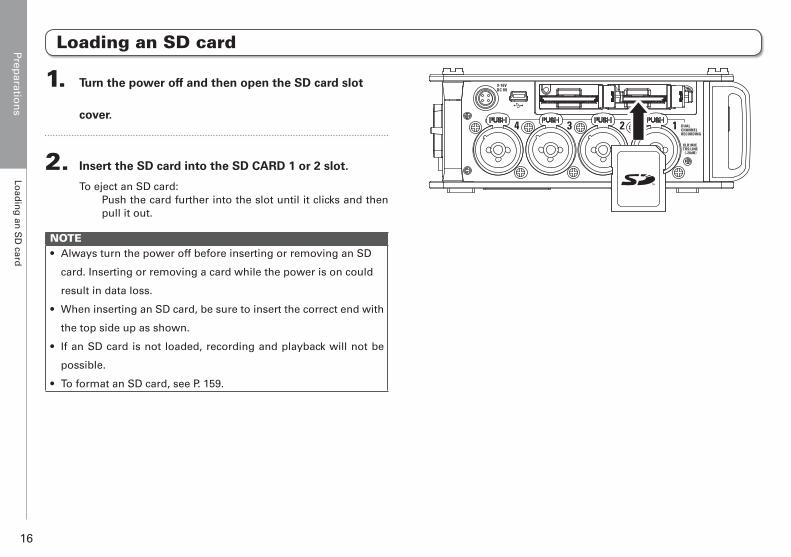
Loading an SD card
1. Turn the power off and then open the SD card slot
cover.
2. Insert the SD card into the SD CARD 1 or 2 slot.
To eject an SD card: Push the card further into the slot until it clicks and then pull it out.
NOTE• Always turn the power off before inserting or removing an SD
card. Inserting or removing a card while the power is on could
result in data loss.
• When inserting an SD card, be sure to insert the correct end with
the top side up as shown.
• If an SD card is not loaded, recording and playback will not be
possible.
• To format an SD card, see P. 159.
Preparatio
ns
Turn
ing
the p
ow
er on
and
off
17
F8 Multi Track Field Recorder
Turning the power on and off
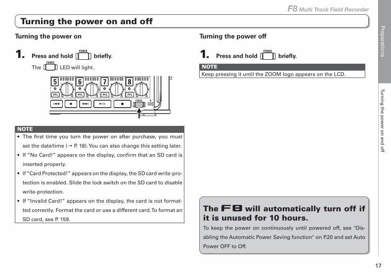
Turning the power on
1. Press and hold briefly.
The LED will light.
NOTE• The first time you turn the power on after purchase, you must
set the date/time (→ P. 18). You can also change this setting later.
• If “No Card!” appears on the display, confirm that an SD card is
inserted properly.
• If “Card Protected!” appears on the display, the SD card write-pro-
tection is enabled. Slide the lock switch on the SD card to disable
write-protection.
• If “Invalid Card!” appears on the display, the card is not format-
ted correctly. Format the card or use a different card. To format an
SD card, see P. 159.
Turning the power off
1. Press and hold briefly.
NOTEKeep pressing it until the ZOOM logo appears on the LCD.
The will automatically turn off if it is unused for 10 hours.To keep the power on continuously until powered off, see "Dis-
abling the Automatic Power Saving function" on P.20 and set Auto
Power OFF to Off.
Preparatio
ns
Settin
g th
e date an
d tim
e (Date/T
ime (R
TC
))
18
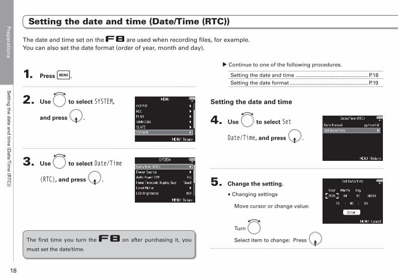
Setting the date and time (Date/Time (RTC))
1. Press .
2. Use to select SYSTEM,
and press .
3. Use to select Date/Time
(RTC), and press .
▶ Continue to one of the following procedures.
Setting the date and time .................................................P.18Setting the date format .....................................................P.19
Setting the date and time
4. Use to select Set
Date/Time, and press .
5. Change the setting.
■ Changing settings
Move cursor or change value:
Turn
Select item to change: Press
The date and time set on the are used when recording files, for example.You can also set the date format (order of year, month and day).
The first time you turn the on after purchasing it, you
must set the date/time.
Preparatio
ns
Settin
g th
e date an
d tim
e (Date/T
ime (R
TC
))
19
F8 Multi Track Field Recorder
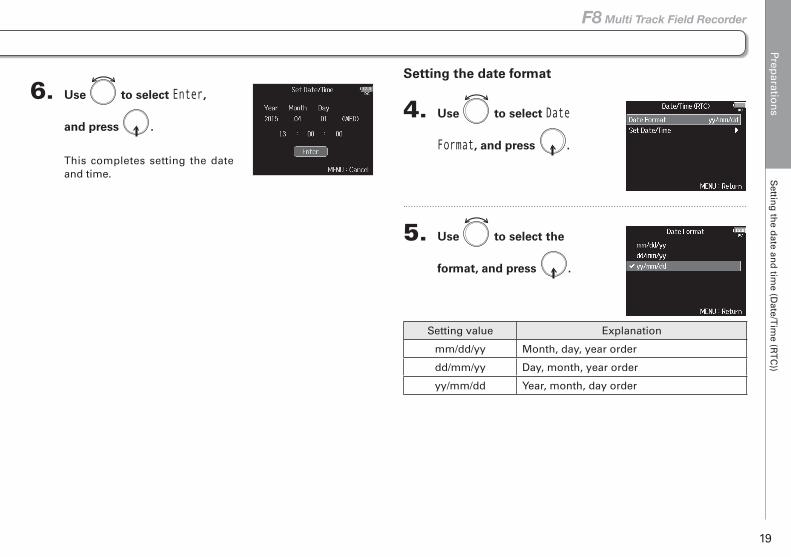
6. Use to select Enter,
and press .
This completes setting the date and time.
Setting the date format
4. Use to select Date
Format, and press .
5. Use to select the
format, and press .
Setting value Explanation
mm/dd/yy Month, day, year order
dd/mm/yy Day, month, year order
yy/mm/dd Year, month, day order
Preparatio
ns
Disab
ling
the A
uto
matic Po
wer S
aving
fun
ction
(Au
to Po
wer O
ff)
20
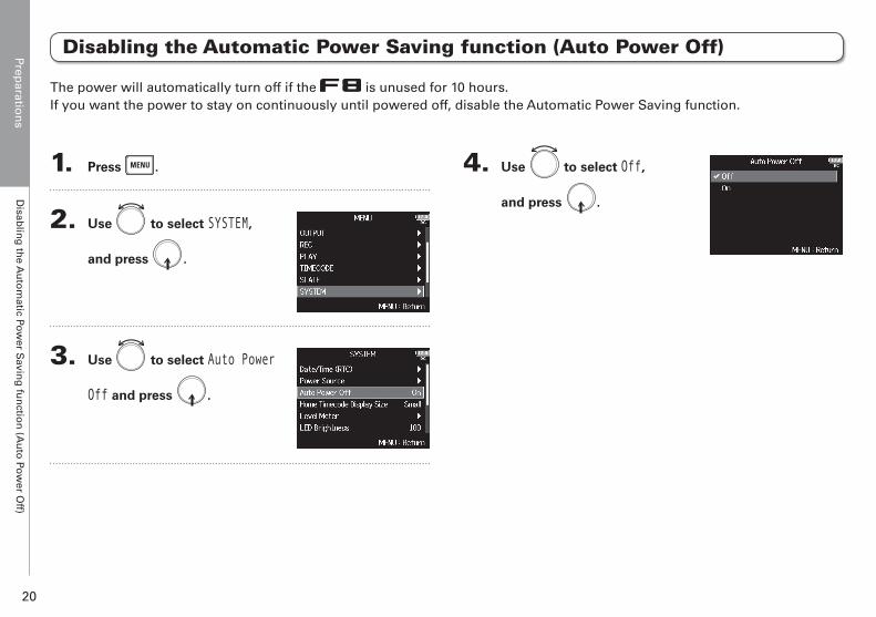
Disabling the Automatic Power Saving function (Auto Power Off)
The power will automatically turn off if the is unused for 10 hours.If you want the power to stay on continuously until powered off, disable the Automatic Power Saving function.
1. Press .
2. Use to select SYSTEM,
and press .
3. Use to select Auto Power
Off and press .
4. Use to select Off,
and press .
Preparatio
ns
Settin
g th
e po
wer su
pp
ly used
(Pow
er So
urce)
21
F8 Multi Track Field Recorder
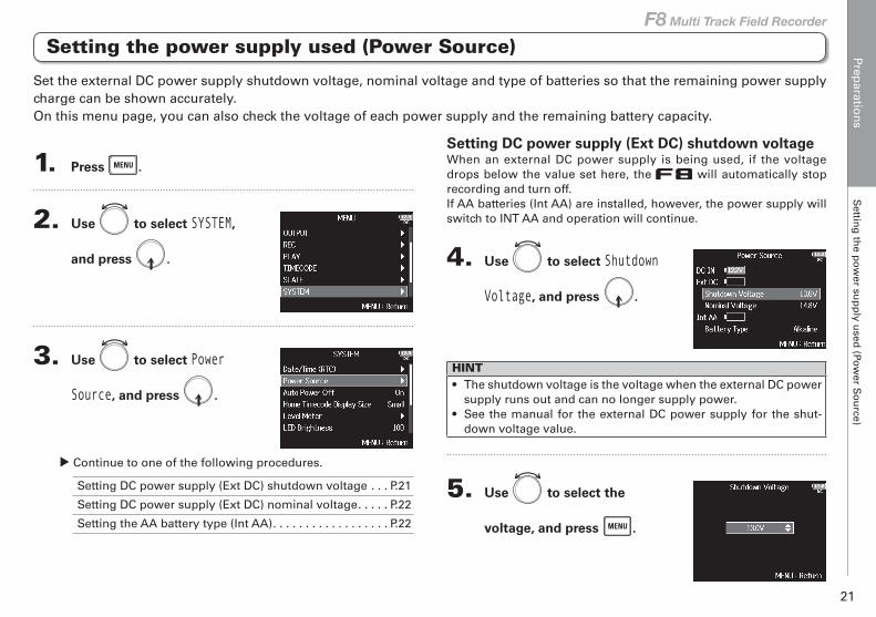
Setting DC power supply (Ext DC) shutdown voltageWhen an external DC power supply is being used, if the voltage drops below the value set here, the will automatically stop recording and turn off.If AA batteries (Int AA) are installed, however, the power supply will switch to INT AA and operation will continue.
4. Use to select Shutdown
Voltage, and press .
HINT• The shutdown voltage is the voltage when the external DC power
supply runs out and can no longer supply power.• See the manual for the external DC power supply for the shut-
down voltage value.
5. Use to select the
voltage, and press .
1. Press .
2. Use to select SYSTEM,
and press .
3. Use to select Power
Source, and press .
▶ Continue to one of the following procedures.
Setting DC power supply (Ext DC) shutdown voltage . . . P.21
Setting DC power supply (Ext DC) nominal voltage. . . . . P.22
Setting the AA battery type (Int AA). . . . . . . . . . . . . . . . . . P.22
Set the external DC power supply shutdown voltage, nominal voltage and type of batteries so that the remaining power supply charge can be shown accurately.On this menu page, you can also check the voltage of each power supply and the remaining battery capacity.
Setting the power supply used (Power Source)
Preparatio
ns
Settin
g th
e po
wer su
pp
ly used
(Pow
er So
urce)
22
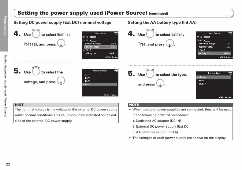
Setting the AA battery type (Int AA)
4. Use to select Battery
Type, and press .
5. Use to select the type,
and press .
NOTE• When multiple power supplies are connected, they will be used
in the following order of precedence.
1. Dedicated AC adapter (DC IN)
2. External DC power supply (Ext DC)
3. AA batteries in unit (Int AA)
• The voltages of each power supply are shown on the display.
Setting DC power supply (Ext DC) nominal voltage
4. Use to select Nominal
Voltage, and press .
5. Use to select the
voltage, and press .
HINTThe nominal voltage is the voltage of the external DC power supply
under normal conditions. This value should be indicated on the out-
side of the external DC power supply.
Setting the power supply used (Power Source) (continued)

Reco
rdin
gR
ecord
ing
pro
cess
23
F8 Multi Track Field Recorder
Recording process
Recording
ConnectTurn poweron (→ P.17)
Prepare beforerecording
Record(→ P.28)
Play backand check(→ P.50)
Check takeinformation(→ P.61)
• Connect mics, instruments, audiovisual equipment and other devices to Inputs 1–8.
(→ P.8)• Connect a mic capsule to the
MIC IN connector. (→ P.9)
• Press to start and to stop recording.
• You can also set marks.• Press to start
recording a new track.• Press to pause
• Press to start playback and or to stop it.
• Marks, for example, can also be set. (→ P.152)
• Check and edit metadata.
1. Set the SD card and file format for recording. (→ P.24)
• Set the recording file format for each SD card separately.
2. Select the recording tracks(→ P.26)
• Use track keys to select. The indicators for selected tracks light red and you will be able to monitor input sounds.
• Press two track keys simultaneously to link them as a stereo track.
3. Make recording settings• Make other settings, including for the
following functions:- dual channel recording (→ P.32)- pre recording (→ P.34)- high pass filter (→ P.80)- limiter (→ P.81)
4. Adjust the input levels(→ P.27)
• Use to adjust each input.
• The s ide mic leve l can a lso be adjusted when using a mid-side mic capsule.
Recording with the follows the process shown below.The data created for each recording occurrence is called a "take".
Reco
rdin
gE
nab
ling
record
ing
on
SD
cards an
d settin
g fi
le form
ats
24
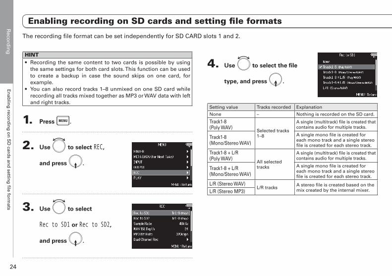
Enabling recording on SD cards and setting file formats
The recording file format can be set independently for SD CARD slots 1 and 2.
HINT• Recording the same content to two cards is possible by using
the same settings for both card slots. This function can be used to create a backup in case the sound skips on one card, for example.
• You can also record tracks 1–8 unmixed on one SD card while recording all tracks mixed together as MP3 or WAV data with left and right tracks.
1. Press .
2. Use to select REC,
and press .
3. Use to select
Rec to SD1 or Rec to SD2,
and press .
4. Use to select the file
type, and press .
Setting value Tracks recorded Explanation
None – Nothing is recorded on the SD card.
Track1-8 (Poly WAV)
Selected tracks 1–8
A single (multitrack) file is created that contains audio for multiple tracks.
Track1-8 (Mono/Stereo WAV)
A single mono file is created for each mono track and a single stereo file is created for each stereo track.
Track1-8 + L/R (Poly WAV)
All selected tracks
A single (multitrack) file is created that contains audio for multiple tracks.
Track1-8 + L/R (Mono/Stereo WAV)
A single mono file is created for each mono track and a single stereo file is created for each stereo track.
L/R (Stereo WAV)L/R tracks A stereo file is created based on the
mix created by the internal mixer.L/R (Stereo MP3)
Reco
rdin
gE
nab
ling
record
ing
on
SD
cards an
d settin
g fi
le form
ats
25
F8 Multi Track Field Recorder
Enabling recording on SD cards and setting file formats
NOTE• When recording with a Mono/Stereo WAV setting, the audio files
are saved in a take folder that is created. (→ P.37)• When recording to 2 SD cards simultaneously, files will be saved
in take folders with the same name on both cards. Folders will be created automatically if they do not already exist.
• If recording should stop on one SD card because, for example, it runs out of space, recording will continue on the other SD card. At such times, do not remove the card that has stopped recording from the slot. Doing so could damage the card or data.
Reco
rdin
gS
electing
inp
uts an
d ad
justin
g levels
26
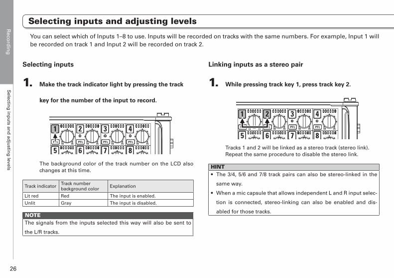
You can select which of Inputs 1–8 to use. Inputs will be recorded on tracks with the same numbers. For example, Input 1 will be recorded on track 1 and Input 2 will be recorded on track 2.
Selecting inputs
1. Make the track indicator light by pressing the track
key for the number of the input to record.
The background color of the track number on the LCD also changes at this time.
Track indicator Track numberbackground color Explanation
Lit red Red The input is enabled.
Unlit Gray The input is disabled.
NOTEThe signals from the inputs selected this way will also be sent to
the L/R tracks.
Linking inputs as a stereo pair
1. While pressing track key 1, press track key 2.
Tracks 1 and 2 will be linked as a stereo track (stereo link). Repeat the same procedure to disable the stereo link.
HINT• The 3/4, 5/6 and 7/8 track pairs can also be stereo-linked in the
same way.
• When a mic capsule that allows independent L and R input selec-
tion is connected, stereo-linking can also be enabled and dis-
abled for those tracks.
Selecting inputs and adjusting levels
Reco
rdin
gS
electing
inp
uts an
d ad
justin
g levels
27
F8 Multi Track Field Recorder
Selecting inputs and adjusting levels
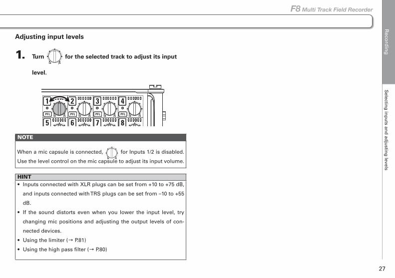
Adjusting input levels
1. Turn for the selected track to adjust its input
level.
NOTE
When a mic capsule is connected, for Inputs 1/2 is disabled.
Use the level control on the mic capsule to adjust its input volume.
HINT• Inputs connected with XLR plugs can be set from +10 to +75 dB,
and inputs connected with TRS plugs can be set from –10 to +55
dB.
• If the sound distorts even when you lower the input level, try
changing mic positions and adjusting the output levels of con-
nected devices.
• Using the limiter (→ P.81)
• Using the high pass filter (→ P.80)
Reco
rdin
gR
ecord
ing
28
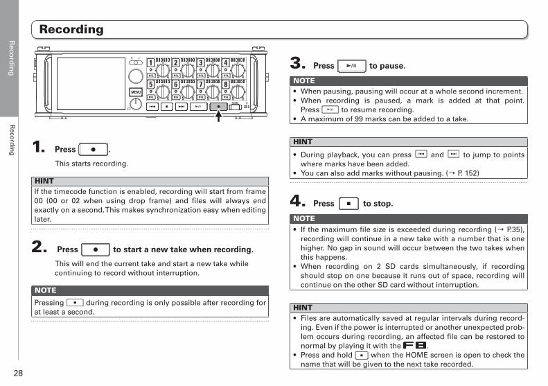
Recording
1. Press .
This starts recording.
HINTIf the timecode function is enabled, recording will start from frame 00 (00 or 02 when using drop frame) and files will always end exactly on a second. This makes synchronization easy when editing later.
2. Press to start a new take when recording.
This will end the current take and start a new take while continuing to record without interruption.
NOTE
Pressing during recording is only possible after recording for at least a second.
3. Press to pause.
NOTE• When pausing, pausing will occur at a whole second increment.• When recording is paused, a mark is added at that point.
Press to resume recording.• A maximum of 99 marks can be added to a take.
HINT
• During playback, you can press and to jump to points where marks have been added.
• You can also add marks without pausing. (→ P. 152)
4. Press to stop.
NOTE• If the maximum file size is exceeded during recording (→ P.35),
recording will continue in a new take with a number that is one higher. No gap in sound will occur between the two takes when this happens.
• When recording on 2 SD cards simultaneously, if recording should stop on one because it runs out of space, recording will continue on the other SD card without interruption.
HINT• Files are automatically saved at regular intervals during record-
ing. Even if the power is interrupted or another unexpected prob-lem occurs during recording, an affected file can be restored to normal by playing it with the .
• Press and hold when the HOME screen is open to check the name that will be given to the next take recorded.
Reco
rdin
gS
etting
the sam
plin
g rate (S
amp
le Rate)
29
F8 Multi Track Field Recorder
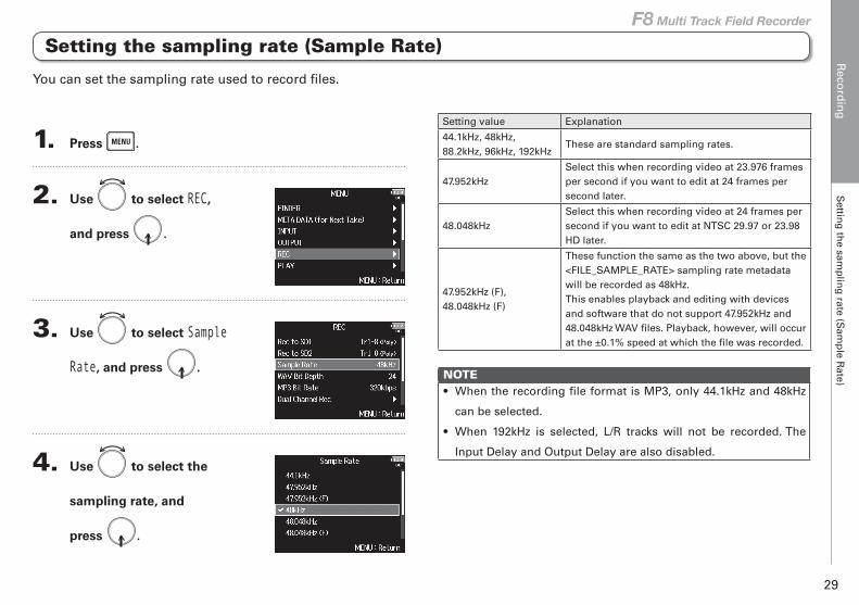
Setting the sampling rate (Sample Rate)
1. Press .
2. Use to select REC,
and press .
3. Use to select Sample
Rate, and press .
4. Use to select the
sampling rate, and
press .
Setting value Explanation
44.1kHz, 48kHz, 88.2kHz, 96kHz, 192kHz
These are standard sampling rates.
47.952kHzSelect this when recording video at 23.976 frames per second if you want to edit at 24 frames per second later.
48.048kHzSelect this when recording video at 24 frames per second if you want to edit at NTSC 29.97 or 23.98 HD later.
47.952kHz (F), 48.048kHz (F)
These function the same as the two above, but the <FILE_SAMPLE_RATE> sampling rate metadata will be recorded as 48kHz.This enables playback and editing with devices and software that do not support 47.952kHz and 48.048kHz WAV files. Playback, however, will occur at the ±0.1% speed at which the file was recorded.
NOTE• When the recording file format is MP3, only 44.1kHz and 48kHz
can be selected.
• When 192kHz is selected, L/R tracks will not be recorded. The
Input Delay and Output Delay are also disabled.
You can set the sampling rate used to record files.
Reco
rdin
gS
etting
WA
V fi
le bit d
epth
(WA
V B
it Dep
th)
30
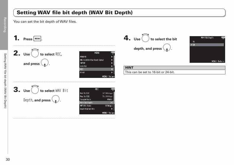
Setting WAV file bit depth (WAV Bit Depth)
1. Press .
2. Use to select REC,
and press .
3. Use to select WAV Bit
Depth, and press .
4. Use to select the bit
depth, and press .
HINTThis can be set to 16-bit or 24-bit.
You can set the bit depth of WAV files.
Reco
rdin
gS
etting
MP
3 file b
it rate (MP
3 Bit R
ate)
31
F8 Multi Track Field Recorder
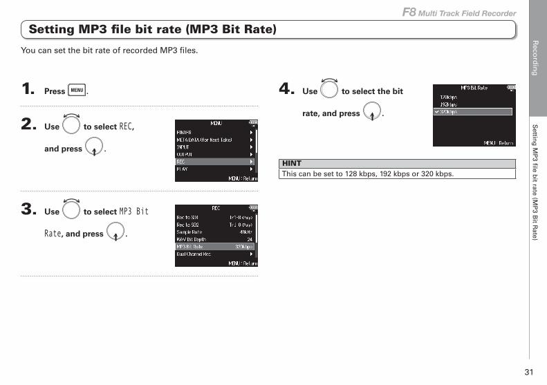
Setting MP3 file bit rate (MP3 Bit Rate)
1. Press .
2. Use to select REC,
and press .
3. Use to select MP3 Bit
Rate, and press .
4. Use to select the bit
rate, and press .
HINTThis can be set to 128 kbps, 192 kbps or 320 kbps.
You can set the bit rate of recorded MP3 files.
Reco
rdin
gS
imu
ltaneo
usly reco
rdin
g tracks at d
ifferent levels (D
ual C
han
nel R
ec)
32
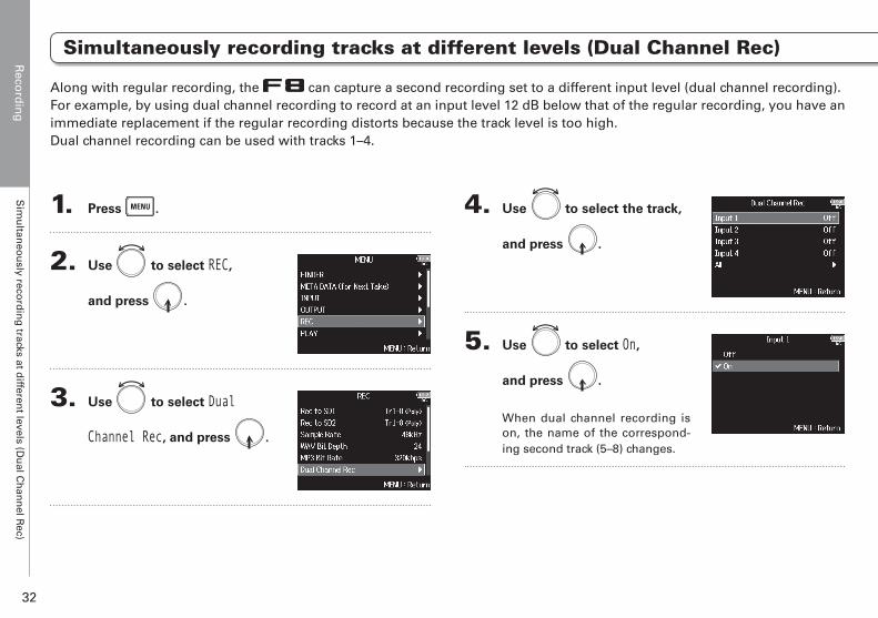
1. Press .
2. Use to select REC,
and press .
3. Use to select Dual
Channel Rec, and press .
4. Use to select the track,
and press .
5. Use to select On,
and press .
When dual channel recording is on, the name of the correspond-ing second track (5–8) changes.
Along with regular recording, the can capture a second recording set to a different input level (dual channel recording).For example, by using dual channel recording to record at an input level 12 dB below that of the regular recording, you have an immediate replacement if the regular recording distorts because the track level is too high.Dual channel recording can be used with tracks 1–4.
Simultaneously recording tracks at different levels (Dual Channel Rec)
Reco
rdin
gS
imu
ltaneo
usly reco
rdin
g tracks at d
ifferent levels (D
ual C
han
nel R
ec)
33
F8 Multi Track Field Recorder
Simultaneously recording tracks at different levels (Dual Channel Rec)
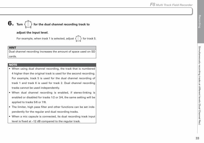
6. Turn for the dual channel recording track to
adjust the input level.
For example, when track 1 is selected, adjust for track 5.
HINTDual channel recording increases the amount of space used on SD
cards.
NOTE• When using dual channel recording, the track that is numbered
4 higher than the original track is used for the second recording.
For example, track 5 is used for the dual channel recording of
track 1 and track 6 is used for track 2. Dual channel recording
tracks cannot be used independently.
• When dual channel recording is enabled, if stereo-linking is
enabled or disabled for tracks 1/2 or 3/4, the same setting will be
applied to tracks 5/6 or 7/8.
• The limiter, high pass filter and other functions can be set inde-
pendently for the regular and dual recording tracks.
• When a mic capsule is connected, its dual recording track input
level is fixed at –12 dB compared to the regular track.
Reco
rdin
gC
aptu
ring
aud
io b
efore reco
rdin
g starts (Pre R
ec)
34
Capturing audio before recording starts (Pre Rec)
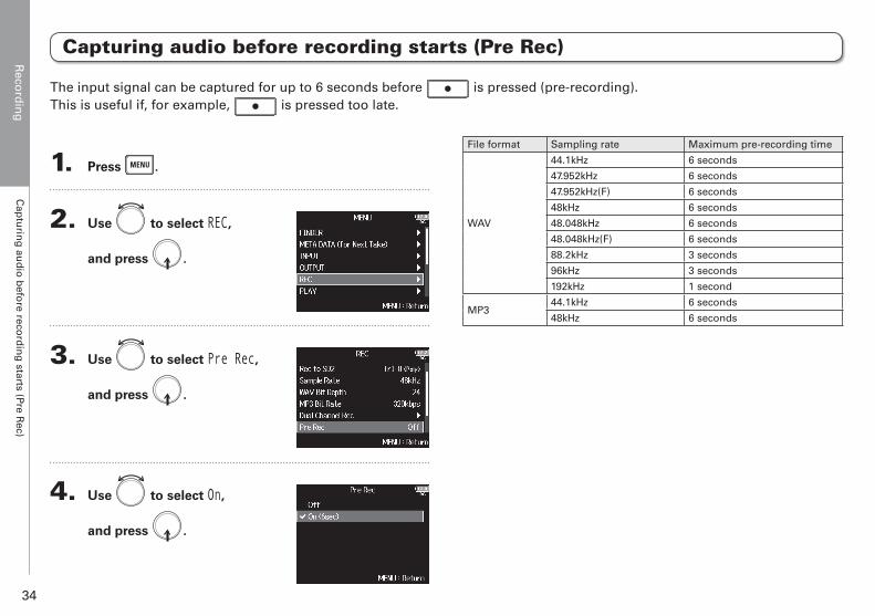
1. Press .
2. Use to select REC,
and press .
3. Use to select Pre Rec,
and press .
4. Use to select On,
and press .
File format Sampling rate Maximum pre-recording time
WAV
44.1kHz 6 seconds
47.952kHz 6 seconds
47.952kHz(F) 6 seconds
48kHz 6 seconds
48.048kHz 6 seconds
48.048kHz(F) 6 seconds
88.2kHz 3 seconds
96kHz 3 seconds
192kHz 1 second
MP344.1kHz 6 seconds
48kHz 6 seconds
The input signal can be captured for up to 6 seconds before is pressed (pre-recording). This is useful if, for example, is pressed too late.
Reco
rdin
gM
aximu
m fi
le size (File Max S
ize)
35
F8 Multi Track Field Recorder
Maximum file size (File Max Size)
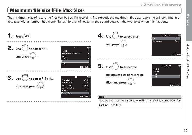
1. Press .
2. Use to select REC,
and press .
3. Use to select File Max
Size, and press .
4. Use to select Size,
and press .
5. Use to select the
maximum size of recording
files, and press .
HINTSetting the maximum size to 640MB or 512MB is convenient for
backing up to CDs.
The maximum size of recording files can be set. If a recording file exceeds the maximum file size, recording will continue in a new take with a number that is one higher. No gap will occur in the sound between the two takes when this happens.
Reco
rdin
gS
ho
win
g to
tal record
ing
times fo
r lon
g reco
rdin
gs (T
ime C
ou
nter)
36
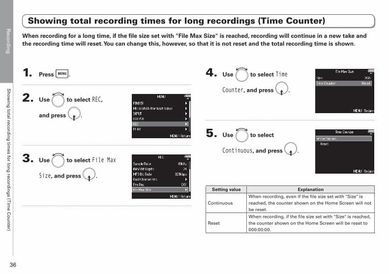
Showing total recording times for long recordings (Time Counter)
1. Press .
2. Use to select REC,
and press .
3. Use to select File Max
Size, and press .
4. Use to select Time
Counter, and press .
5. Use to select
Continuous, and press .
Setting value Explanation
ContinuousWhen recording, even if the file size set with "Size" is reached, the counter shown on the Home Screen will not be reset.
ResetWhen recording, if the file size set with "Size" is reached, the counter shown on the Home Screen will be reset to 000:00:00.
When recording for a long time, if the file size set with "File Max Size" is reached, recording will continue in a new take and the recording time will reset. You can change this, however, so that it is not reset and the total recording time is shown.
Reco
rdin
gFo
lder an
d fi
le structu
re
37
F8 Multi Track Field Recorder
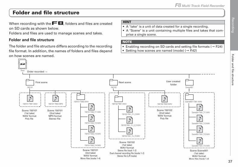
HINT• A "take" is a unit of data created for a single recording.• A "Scene" is a unit containing multiple files and takes that com-
prise a single scene.
Folder and file structure
The folder and file structure differs according to the recording file format. In addition, the names of folders and files depend on how scenes are named.
When recording with the , folders and files are created on SD cards as shown below.Folders and files are used to manage scenes and takes.
NOTE• Enabling recording on SD cards and setting file formats (→ P.24)• Setting how scenes are named (mode) (→ P.42)
150101-T001.WAV
150101-T003_Tr3.WAV
150101-T003_Tr4.WAV
150101-T003_Tr1.WAV
150101-T003.WAV Scene001-T001.WAV
150101-T003_Tr2.WAV
150102 Scene001
Root
Scene 150101(1st take)
WAV formatPoly file
Next scene
150101
First scene User created folder
Order recorded →
150101-T002.MP3
Scene 150101(2nd take)
MP3 formatStereo file
Scene 150101(3rd take)
WAV formatMono files (tracks 1–4)
Scene001-T001_Tr3.WAV
Scene001-T001_Tr4.WAV
Scene001-T001_Tr1.WAV
Scene001-T001_Tr2.WAV
Scene Scene001(1st take)
WAV formatMono files (tracks 1–4)
150102-T001_TrL_R.WAV
150102-T001_Tr1_2.WAV
150102-T001.WAV
150102-T001_Tr1_2_D.WAV
Scene 150102(1st take)
WAV formatStereo file (track 1–2)
Dual channel recording file (tracks 1–2)Stereo file (L/R tracks)
150102-T002.WAV
Scene 150102(2nd take)
WAV formatPoly file
Folder and file structure
Reco
rdin
gFo
lder an
d fi
le structu
re
38
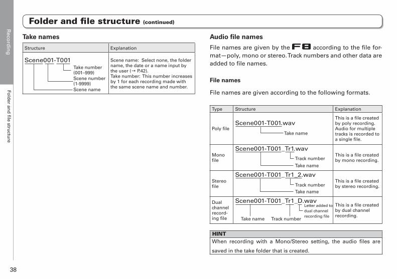
Take names
Structure Explanation
Scene001-T001Take number(001–999)Scene number(1-9999)Scene name
Scene name: Select none, the folder name, the date or a name input by the user (→ P.42). Take number: This number increases by 1 for each recording made with the same scene name and number.
Audio file names
File names are given by the according to the file for-mat—poly, mono or stereo. Track numbers and other data are added to file names.
File names
File names are given according to the following formats.
Type Structure Explanation
Poly fileScene001-T001.wav
Take name
This is a file created by poly recording.Audio for multiple tracks is recorded to a single file.
Mono file
Scene001-T001_Tr1.wav
Take name
Track numberThis is a file created by mono recording.
Stereo file
Scene001-T001_Tr1_2.wav
Take nameTrack number
This is a file created by stereo recording.
Dual channel record-ing file
Scene001-T001_Tr1_D.wav
Take name Track number
Letter added to dual channel recording file
This is a file created by dual channel recording.
HINTWhen recording with a Mono/Stereo setting, the audio files are
saved in the take folder that is created.
Folder and file structure (continued)
Reco
rdin
gM
oving
the p
reviou
sly record
ed take to
the FA
LSE
TAK
E fo
lder
39
F8 Multi Track Field Recorder
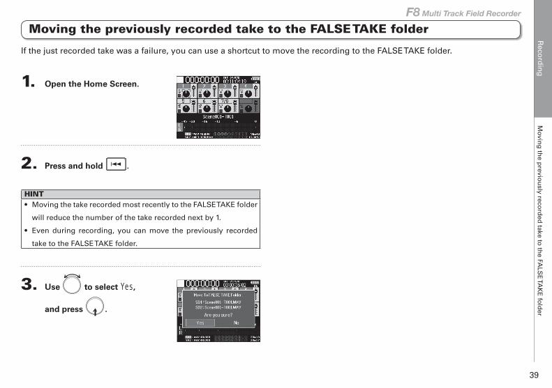
1. Open the Home Screen.
2. Press and hold .
HINT• Moving the take recorded most recently to the FALSE TAKE folder
will reduce the number of the take recorded next by 1.
• Even during recording, you can move the previously recorded
take to the FALSE TAKE folder.
3. Use to select Yes,
and press .
Moving the previously recorded take to the FALSE TAKE folder
If the just recorded take was a failure, you can use a shortcut to move the recording to the FALSE TAKE folder.
Recording take settings
Reco
rdin
g take settin
gs
Ch
ang
ing
the n
ote fo
r the n
ext take record
ed (N
ote)
40
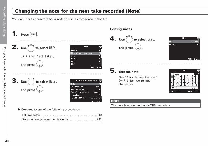
1. Press .
2. Use to select META
DATA (for Next Take),
and press .
3. Use to select Note,
and press .
▶ Continue to one of the following procedures.
Editing notes . . . . . . . . . . . . . . . . . . . . . . . . . . . . . . . . . . . . P.40
Selecting notes from the history list . . . . . . . . . . . . . . . . . P.41
Editing notes
4. Use to select Edit,
and press .
5. Edit the note.
See "Character input screen" (→ P.13) for how to input characters.
NOTEThis note is written to the <NOTE> metadata.
You can input characters for a note to use as metadata in the file.
Changing the note for the next take recorded (Note)
Reco
rdin
g take settin
gs
Ch
ang
ing
the n
ote fo
r the n
ext take record
ed (N
ote)
41
F8 Multi Track Field Recorder
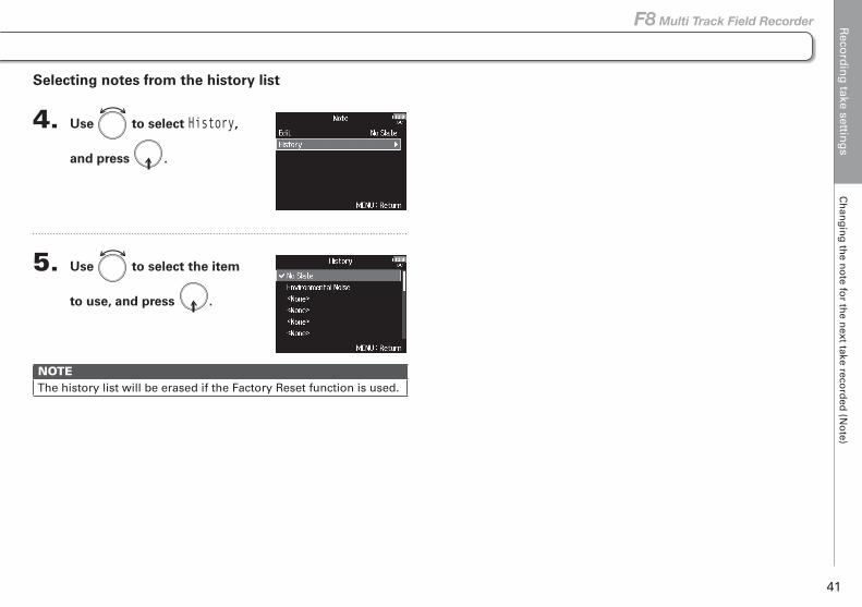
Selecting notes from the history list
4. Use to select History,
and press .
5. Use to select the item
to use, and press .
NOTEThe history list will be erased if the Factory Reset function is used.
Reco
rdin
g take settin
gs
Settin
g h
ow
record
ed scen
es are nam
ed an
d n
um
bered
42
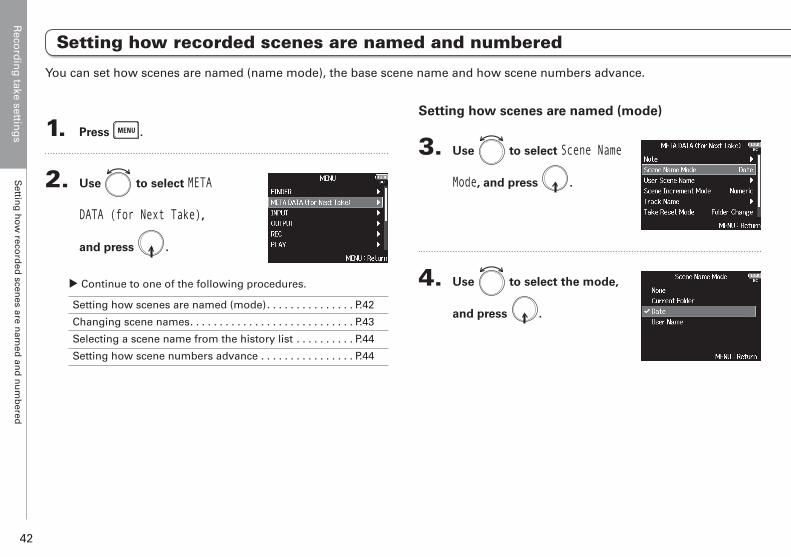
1. Press .
2. Use to select META
DATA (for Next Take),
and press .
▶ Continue to one of the following procedures.
Setting how scenes are named (mode). . . . . . . . . . . . . . . P.42
Changing scene names. . . . . . . . . . . . . . . . . . . . . . . . . . . . P.43
Selecting a scene name from the history list . . . . . . . . . . P.44
Setting how scene numbers advance . . . . . . . . . . . . . . . . P.44
Setting how scenes are named (mode)
3. Use to select Scene Name
Mode, and press .
4. Use to select the mode,
and press .
Setting how recorded scenes are named and numbered
You can set how scenes are named (name mode), the base scene name and how scene numbers advance.
Reco
rdin
g take settin
gs
Settin
g h
ow
record
ed scen
es are nam
ed an
d n
um
bered
43
F8 Multi Track Field Recorder
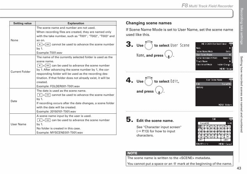
Changing scene names
If Scene Name Mode is set to User Name, set the scene name used like this.
3. Use to select User Scene
Name, and press .
4. Use to select Edit,
and press .
5. Edit the scene name.
See "Character input screen" (→ P.13) for how to input characters.
NOTEThe scene name is written to the <SCENE> metadata.
You cannot put a space or an @ mark at the beginning of the name.
Setting value Explanation
None
The scene name and number are not used.When recording files are created, they are named only with the take number, such as "T001", "T002", "T003" and so on.
+ cannot be used to advance the scene number by 1.Example: T001.wav
Current Folder
The name of the currently selected folder is used as the scene name.
+ can be used to advance the scene number by 1. After advancing the scene number by 1, the cor-responding folder will be used as the recording des-tination. If that folder does not already exist, it will be created.Example: FOLDER001-T001.wav
Date
The date is used as the scene name.+ cannot be used to advance the scene number
by 1.If recording occurs after the date changes, a scene folder with the date will be created.Example: 20150101-T001.wav
User Name
A scene name input by the user is used.+ can be used to advance the scene number
by 1.No folder is created in this case.Example: MYSCENE001-T001.wav
Reco
rdin
g take settin
gs
Settin
g h
ow
record
ed scen
es are nam
ed an
d n
um
bered
44
Setting how recorded scenes are named and numbered (continued)
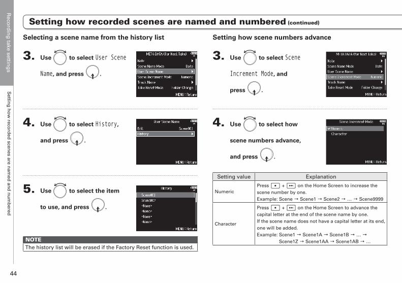
Setting how scene numbers advance
3. Use to select Scene
Increment Mode, and
press .
4. Use to select how
scene numbers advance,
and press .
Setting value Explanation
NumericPress + on the Home Screen to increase the scene number by one.Example: Scene → Scene1 → Scene2 → … → Scene9999
Character
Press + on the Home Screen to advance the capital letter at the end of the scene name by one.If the scene name does not have a capital letter at its end, one will be added.Example: Scene1 → Scene1A → Scene1B → … →
Scene1Z → Scene1AA → Scene1AB → …
Selecting a scene name from the history list
3. Use to select User Scene
Name, and press .
4. Use to select History,
and press .
5. Use to select the item
to use, and press .
NOTEThe history list will be erased if the Factory Reset function is used.
Reco
rdin
g take settin
gs
Settin
g h
ow
record
ed scen
es are nam
ed an
d n
um
bered
45
F8 Multi Track Field Recorder
Setting how recorded scenes are named and numbered (continued)
HINT
On the Home Screen, + can be used to advance the scene
number by one.

Reco
rdin
g take settin
gs
Settin
g th
e take reset con
ditio
n an
d n
um
berin
g fo
rmat
46
Setting the take reset condition and numbering format
1. Press .
2. Use to select META
DATA (for Next Take),
and press .
▶ Continue to one of the following procedures.
Setting the take number reset condition . . . . . . . . . . . . . . P.46
Setting the take name format. . . . . . . . . . . . . . . . . . . . . . . P.47
Setting the take number reset condition
3. Use to select Take Reset
Mode, and press .
4. Use to select the reset
mode, and press .
Setting value Explanation
Off
The take number will not be reset.However, if the folder is changed and that folder con-tains a number higher than the current take number, the take number will be set to one higher than the highest existing take number.
Folder ChangeIf the destination folder is changed, the take number will be set to one higher than the highest take number in that folder.
You can set the take number reset condition and take number format used when recording.
Reco
rdin
g take settin
gs
Settin
g th
e take reset con
ditio
n an
d n
um
berin
g fo
rmat
47
F8 Multi Track Field Recorder
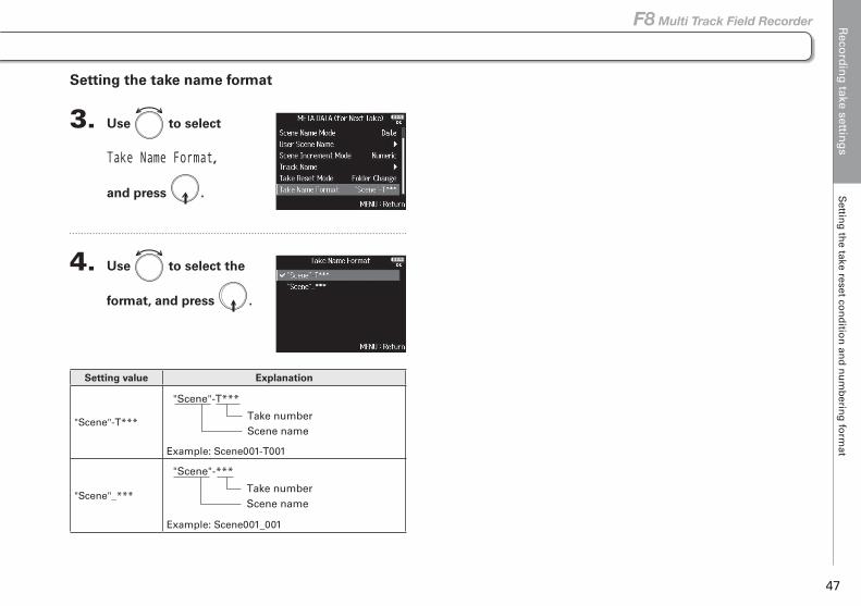
Setting the take name format
3. Use to select
Take Name Format,
and press .
4. Use to select the
format, and press .
Setting value Explanation
"Scene"-T***
Example: Scene001-T001
"Scene"_***
Example: Scene001_001
"Scene"-T***
Take numberScene name
"Scene"-***
Take numberScene name
Reco
rdin
g take settin
gs
Ch
ang
ing
the track n
ame o
f the n
ext take record
ed (Track N
ame)
48
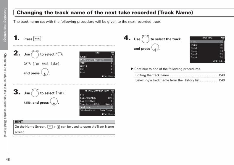
1. Press .
2. Use to select META
DATA (for Next Take),
and press .
3. Use to select Track
Name, and press .
HINT
On the Home Screen, + can be used to open the Track Name
screen.
4. Use to select the track,
and press .
▶ Continue to one of the following procedures.
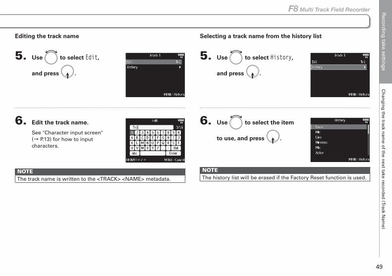
Editing the track name . . . . . . . . . . . . . . . . . . . . . . . . . . . . P.49
Selecting a track name from the History list . . . . . . . . . . . P.49
Changing the track name of the next take recorded (Track Name)
The track name set with the following procedure will be given to the next recorded track.
Reco
rdin
g take settin
gs
Ch
ang
ing
the track n
ame o
f the n
ext take record
ed (Track N
ame)
49
F8 Multi Track Field Recorder
Editing the track name
5. Use to select Edit,
and press .
6. Edit the track name.
See "Character input screen" (→ P.13) for how to input characters.
NOTEThe track name is written to the <TRACK> <NAME> metadata.
Selecting a track name from the history list
5. Use to select History,
and press .
6. Use to select the item
to use, and press .
NOTEThe history list will be erased if the Factory Reset function is used.
Playb
ackP
laying
record
ing
s
50
Playback
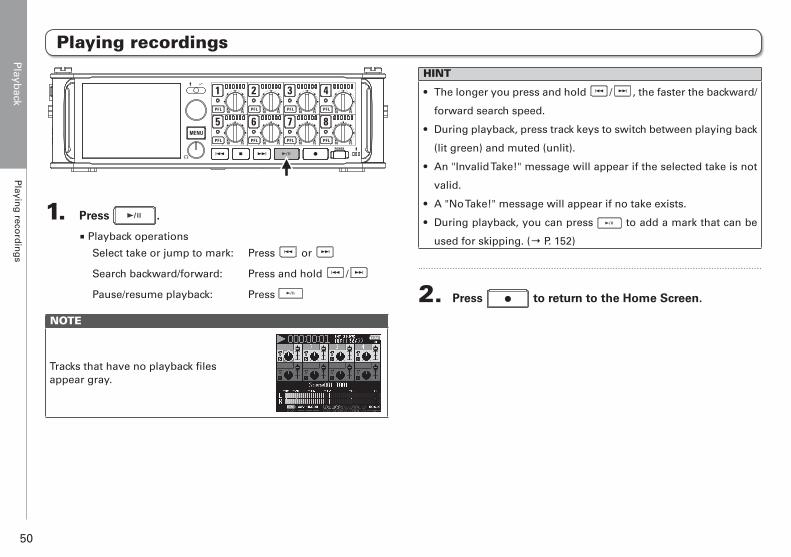
1. Press .
■ Playback operations
Select take or jump to mark: Press or
Search backward/forward: Press and hold /
Pause/resume playback: Press
NOTE
Tracks that have no playback files appear gray.
HINT
• The longer you press and hold / , the faster the backward/
forward search speed.
• During playback, press track keys to switch between playing back
(lit green) and muted (unlit).
• An "Invalid Take!" message will appear if the selected take is not
valid.
• A "No Take!" message will appear if no take exists.
• During playback, you can press to add a mark that can be
used for skipping. (→ P. 152)
2. Press to return to the Home Screen.
Playing recordings
Playb
ackM
ixing
takes
51
F8 Multi Track Field Recorder
Mixing takes
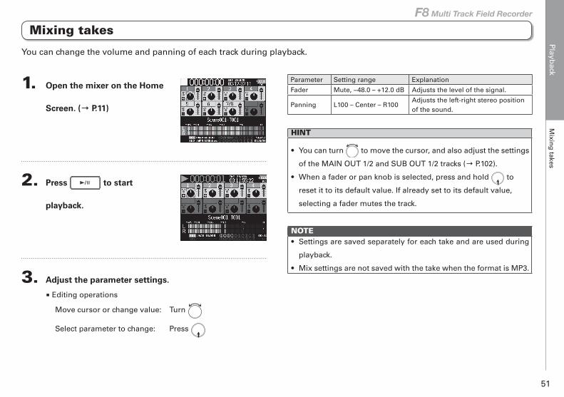
1. Open the mixer on the Home
Screen. (→ P.11)
2. Press to start
playback.
3. Adjust the parameter settings.
■ Editing operations
Move cursor or change value: Turn
Select parameter to change: Press
Parameter Setting range Explanation
Fader Mute, −48.0 – +12.0 dB Adjusts the level of the signal.
Panning L100 – Center – R100Adjusts the left-right stereo position of the sound.
HINT
• You can turn to move the cursor, and also adjust the settings
of the MAIN OUT 1/2 and SUB OUT 1/2 tracks (→ P.102).
• When a fader or pan knob is selected, press and hold to
reset it to its default value. If already set to its default value,
selecting a fader mutes the track.
NOTE• Settings are saved separately for each take and are used during
playback.
• Mix settings are not saved with the take when the format is MP3.
You can change the volume and panning of each track during playback.
Playb
ackM
on
itorin
g th
e playb
ack sign
als of sp
ecific tracks d
urin
g p
layback
52
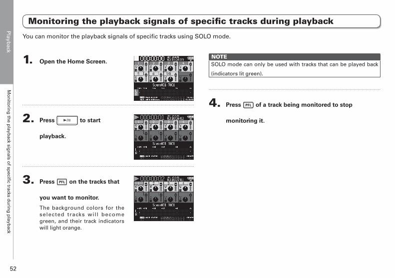
You can monitor the playback signals of specific tracks using SOLO mode.
NOTESOLO mode can only be used with tracks that can be played back
(indicators lit green).
4. Press of a track being monitored to stop
monitoring it.
Monitoring the playback signals of specific tracks during playback
1. Open the Home Screen.
2. Press to start
playback.
3. Press on the tracks that
you want to monitor.
The background colors for the selected tracks wil l become green, and their track indicators will light orange.
Playb
ackC
han
gin
g th
e playb
ack mo
de (P
lay Mo
de)
53
F8 Multi Track Field Recorder
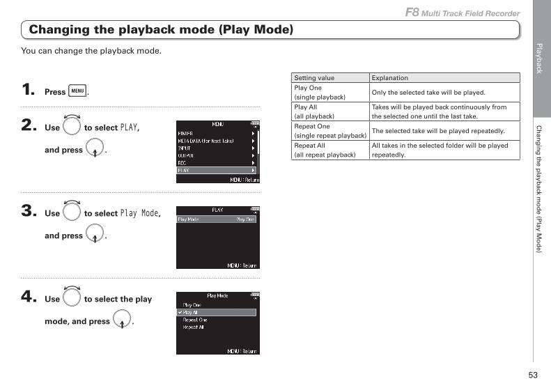
Changing the playback mode (Play Mode)
1. Press .
2. Use to select PLAY,
and press .
3. Use to select Play Mode,
and press .
4. Use to select the play
mode, and press .
Setting value Explanation
Play One(single playback)
Only the selected take will be played.
Play All(all playback)
Takes will be played back continuously from the selected one until the last take.
Repeat One(single repeat playback)
The selected take will be played repeatedly.
Repeat All(all repeat playback)
All takes in the selected folder will be played repeatedly.
You can change the playback mode.
Take and
fold
er op
eration
sTake an
d fo
lder o
peratio
ns (FIN
DE
R)
54
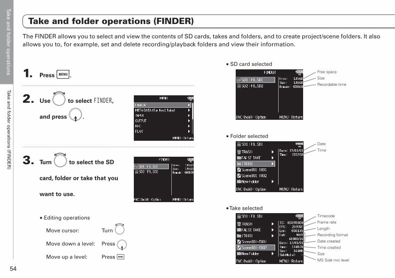
Take and folder operations (FINDER)
Take and folder operations
1. Press .
2. Use to select FINDER,
and press .
3. Turn to select the SD
card, folder or take that you
want to use.
■ Editing operations
Move cursor: Turn
Move down a level: Press
Move up a level: Press
■ SD card selectedFree space
Size
Recordable time
■ Folder selectedDate
Time
■ Take selectedTimecode
Frame rate
Length
Recording format
Date created
Time created
Size
MS Side mic level
The FINDER allows you to select and view the contents of SD cards, takes and folders, and to create project/scene folders. It also allows you to, for example, set and delete recording/playback folders and view their information.
Take and
fold
er op
eration
sTake an
d fo
lder o
peratio
ns (FIN
DE
R)
55
F8 Multi Track Field Recorder
Take and folder operations (FINDER)
NOTE
• When the cursor is on a take, you can press to play the
selected take. You can also use , and .
• A check mark appears on the playback take and recording/play-
back folder.
▶ Continue to one of the following procedures.
Creating folders .................................................................P.55Selecting the take recording/playback folder ..................P.56Checking take marks and using them for playback ........P.56Changing folder and take names .....................................P.57Copying takes to other cards and folders .......................P.57Deleting folders and takes ................................................P.58Emptying the TRASH/FALSE TAKE folder.........................P.59
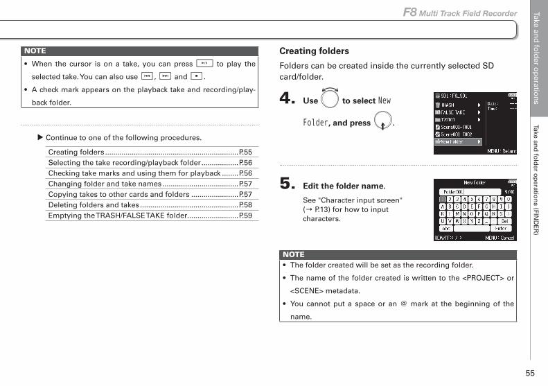
Creating folders
Folders can be created inside the currently selected SD card/folder.
4. Use to select New
Folder, and press .
5. Edit the folder name.
See "Character input screen" (→ P.13) for how to input characters.
NOTE• The folder created will be set as the recording folder.
• The name of the folder created is written to the <PROJECT> or
<SCENE> metadata.
• You cannot put a space or an @ mark at the beginning of the
name.
Take and
fold
er op
eration
sTake an
d fo
lder o
peratio
ns (FIN
DE
R)
56
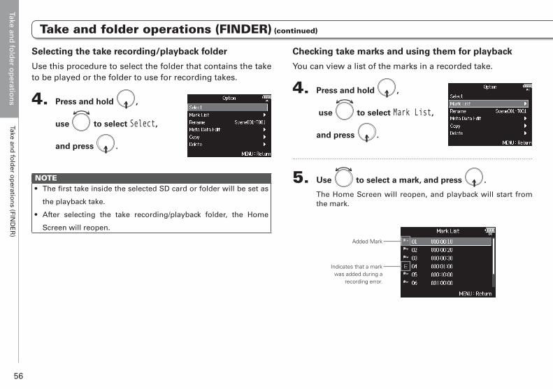
Checking take marks and using them for playback
You can view a list of the marks in a recorded take.
4. Press and hold ,
use to select Mark List,
and press .
5. Use to select a mark, and press .
The Home Screen will reopen, and playback will start from the mark.
Added Mark
Indicates that a mark was added during a
recording error.
Selecting the take recording/playback folder
Use this procedure to select the folder that contains the take to be played or the folder to use for recording takes.
4. Press and hold ,
use to select Select,
and press .
NOTE• The first take inside the selected SD card or folder will be set as
the playback take.
• After selecting the take recording/playback folder, the Home
Screen will reopen.
Take and folder operations (FINDER) (continued)
Take and
fold
er op
eration
sTake an
d fo
lder o
peratio
ns (FIN
DE
R)
57
F8 Multi Track Field Recorder
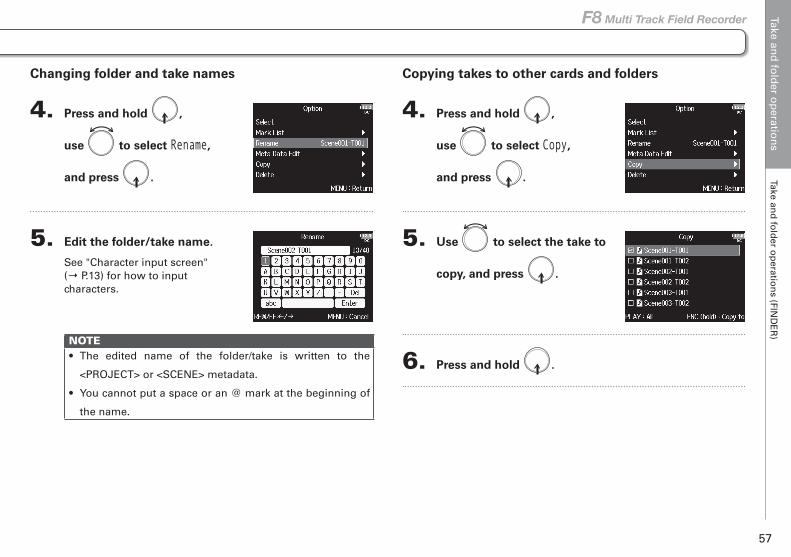
Copying takes to other cards and folders
4. Press and hold ,
use to select Copy,
and press .
5. Use to select the take to
copy, and press .
6. Press and hold .
Changing folder and take names
4. Press and hold ,
use to select Rename,
and press .
5. Edit the folder/take name.
See "Character input screen" (→ P.13) for how to input characters.
NOTE• The edited name of the folder/take is written to the
<PROJECT> or <SCENE> metadata.
• You cannot put a space or an @ mark at the beginning of
the name.
Take and folder operations (FINDER) (continued)
Take and
fold
er op
eration
sTake an
d fo
lder o
peratio
ns (FIN
DE
R)
58
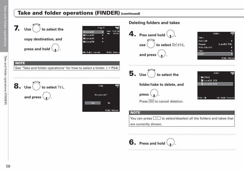
Deleting folders and takes
4. Pres sand hold ,
use to select Delete,
and press .
5. Use to select the
folder/take to delete, and
press .
Press to cancel deletion.
NOTE
You can press to select/deselect all the folders and takes that
are currently shown.
6. Press and hold .
7. Use to select the
copy destination, and
press and hold .
NOTESee "Take and folder operations" for how to select a folder. (→ P.54)
8. Use to select Yes,
and press .
Take and folder operations (FINDER) (continued)
Take and
fold
er op
eration
sTake an
d fo
lder o
peratio
ns (FIN
DE
R)
59
F8 Multi Track Field Recorder
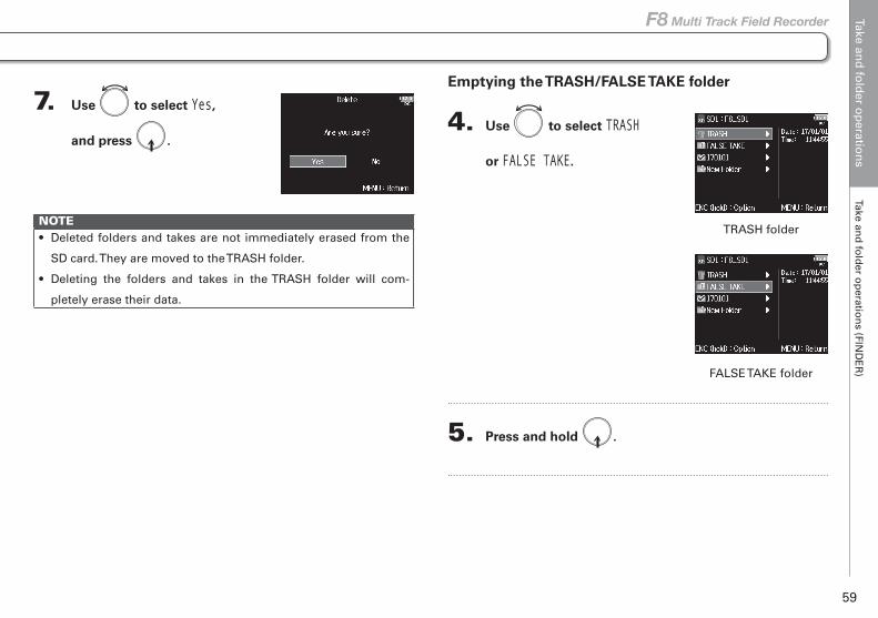
Emptying the TRASH/FALSE TAKE folder
4. Use to select TRASH
or FALSE TAKE.
5. Press and hold .
7. Use to select Yes,
and press .
NOTE• Deleted folders and takes are not immediately erased from the
SD card. They are moved to the TRASH folder.
• Deleting the folders and takes in the TRASH folder will com-
pletely erase their data.
Take and folder operations (FINDER) (continued)
TRASH folder
FALSE TAKE folder
Take and
fold
er op
eration
sTake an
d fo
lder o
peratio
ns (FIN
DE
R)
60
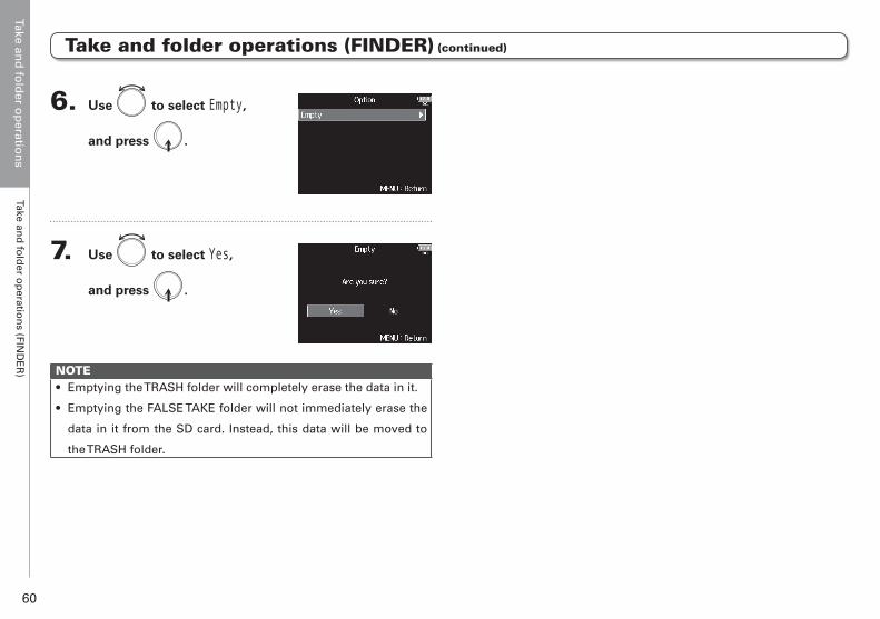
6. Use to select Empty,
and press .
7. Use to select Yes,
and press .
NOTE• Emptying the TRASH folder will completely erase the data in it.
• Emptying the FALSE TAKE folder will not immediately erase the
data in it from the SD card. Instead, this data will be moved to
the TRASH folder.
Take and folder operations (FINDER) (continued)
Take and
fold
er op
eration
sIn
form
ation
(metad
ata) stored
in fi
les
61
F8 Multi Track Field Recorder
The writes a variety of information (metadata) to files during recording.When these files are read by an application that supports metadata, you will be able to check and use the saved information.
HINT• Metadata is data that contains information related to other data.
The saves scene names and take numbers, for example,
as metadata in audio files.
• A chunk is a unit that contains multiple data in a single block.
• To use BEXT and iXML chunk metadata, an application that sup-
ports both data formats is necessary.
WAV file metadata
The metadata saved in files recorded by the in WAV format is collected in BEXT (Broadcast Audio Extension) and iXML chunks. For information about the metadata saved in these chunks, see the “Metadata contained in BEXT chunks in WAV files” (→ P.169) and “Metadata contained in iXML chunks in WAV files” (→ P.170).
MP3 file metadata
The metadata saved in files recorded by the in MP3 format is written as ID3v1 tags.For information about the ID3 fields and formats for saving metadata, see the "Metadata and ID3 fields contained in MP3 files" (→ P.172).
HINT
• MP3 files conform to the MPEG-1 Layer III standard.
• MP3 metadata cannot be edited.
Information (metadata) stored in files
Take and
fold
er op
eration
sC
heckin
g an
d ed
iting
take metad
ata
62
Checking and editing take metadata
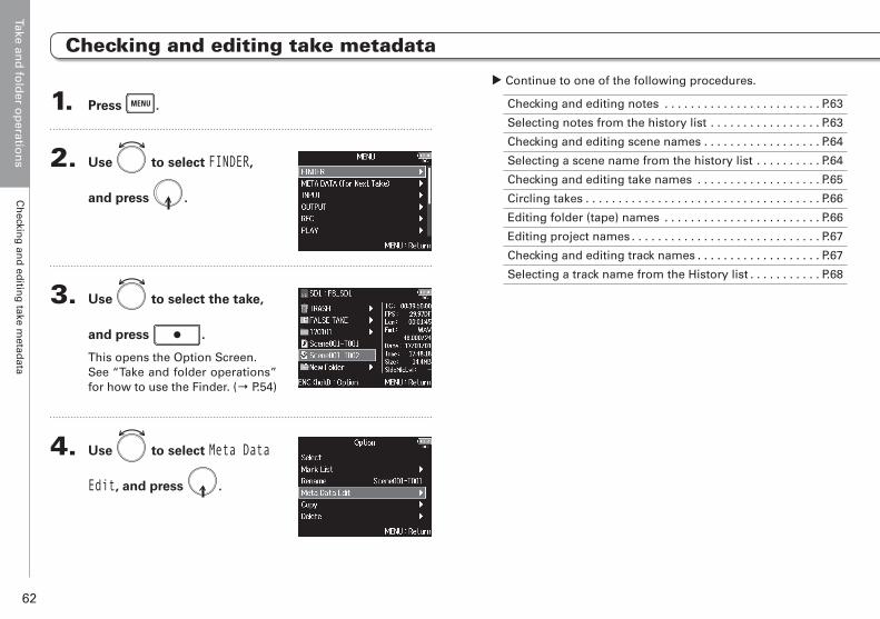
1. Press .
2. Use to select FINDER,
and press .
3. Use to select the take,
and press .
This opens the Option Screen.See “Take and folder operations” for how to use the Finder. (→ P.54)
4. Use to select Meta Data
Edit, and press .
▶ Continue to one of the following procedures.
Checking and editing notes . . . . . . . . . . . . . . . . . . . . . . . . P.63
Selecting notes from the history list . . . . . . . . . . . . . . . . . P.63
Checking and editing scene names . . . . . . . . . . . . . . . . . . P.64
Selecting a scene name from the history list . . . . . . . . . . P.64
Checking and editing take names . . . . . . . . . . . . . . . . . . . P.65
Circling takes . . . . . . . . . . . . . . . . . . . . . . . . . . . . . . . . . . . . P.66
Editing folder (tape) names . . . . . . . . . . . . . . . . . . . . . . . . P.66
Editing project names . . . . . . . . . . . . . . . . . . . . . . . . . . . . . P.67
Checking and editing track names . . . . . . . . . . . . . . . . . . . P.67
Selecting a track name from the History list . . . . . . . . . . . P.68
Take and
fold
er op
eration
sC
heckin
g an
d ed
iting
take metad
ata
63
F8 Multi Track Field Recorder
Checking and editing take metadata
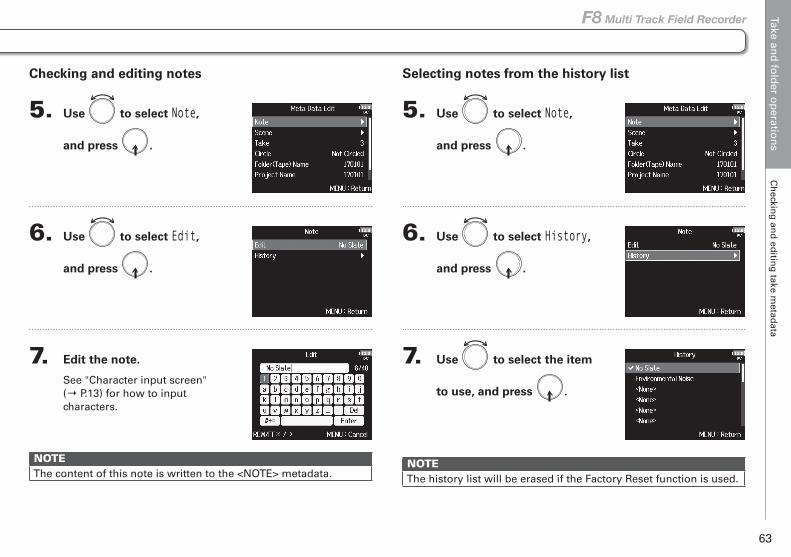
Checking and editing notes
5. Use to select Note,
and press .
6. Use to select Edit,
and press .
7. Edit the note.
See "Character input screen" (→ P.13) for how to input characters.
NOTEThe content of this note is written to the <NOTE> metadata.
Selecting notes from the history list
5. Use to select Note,
and press .
6. Use to select History,
and press .
7. Use to select the item
to use, and press .
NOTEThe history list will be erased if the Factory Reset function is used.
Take and
fold
er op
eration
sC
heckin
g an
d ed
iting
take metad
ata
64
Checking and editing take metadata (continued)
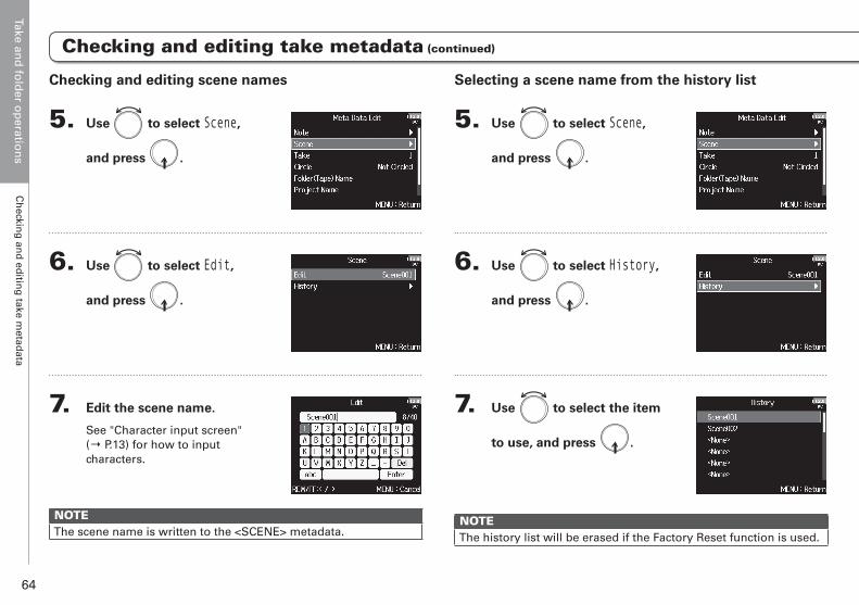
Selecting a scene name from the history list
5. Use to select Scene,
and press .
6. Use to select History,
and press .
7. Use to select the item
to use, and press .
NOTEThe history list will be erased if the Factory Reset function is used.
Checking and editing scene names
5. Use to select Scene,
and press .
6. Use to select Edit,
and press .
7. Edit the scene name.
See "Character input screen" (→ P.13) for how to input characters.
NOTEThe scene name is written to the <SCENE> metadata.
Take and
fold
er op
eration
sC
heckin
g an
d ed
iting
take metad
ata
65
F8 Multi Track Field Recorder
Checking and editing take metadata (continued)
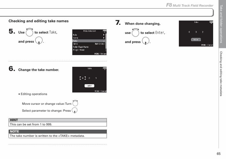
7. When done changing,
use to select Enter,
and press .
Checking and editing take names
5. Use to select Take,
and press .
6. Change the take number.
■ Editing operations
Move cursor or change value: Turn
Select parameter to change: Press
HINTThis can be set from 1 to 999.
NOTEThe take number is written to the <TAKE> metadata.
Take and
fold
er op
eration
sC
heckin
g an
d ed
iting
take metad
ata
66
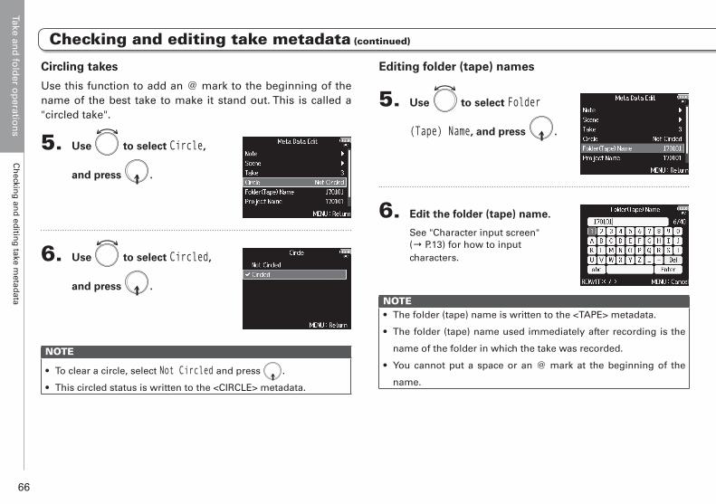
Editing folder (tape) names
5. Use to select Folder
(Tape) Name, and press .
6. Edit the folder (tape) name.
See "Character input screen" (→ P.13) for how to input characters.
NOTE• The folder (tape) name is written to the <TAPE> metadata.
• The folder (tape) name used immediately after recording is the
name of the folder in which the take was recorded.
• You cannot put a space or an @ mark at the beginning of the
name.
Circling takes
Use this function to add an @ mark to the beginning of the name of the best take to make it stand out. This is called a "circled take".
5. Use to select Circle,
and press .
6. Use to select Circled,
and press .
NOTE
• To clear a circle, select Not Circled and press .
• This circled status is written to the <CIRCLE> metadata.
Checking and editing take metadata (continued)
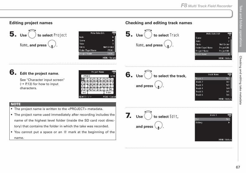
Take and
fold
er op
eration
sC
heckin
g an
d ed
iting
take metad
ata
67
F8 Multi Track Field Recorder
Editing project names
5. Use to select Project
Name, and press .
6. Edit the project name.
See "Character input screen" (→ P.13) for how to input characters.
NOTE• The project name is written to the <PROJECT> metadata.
• The project name used immediately after recording includes the
name of the highest level folder (inside the SD card root direc-
tory) that contains the folder in which the take was recorded.
• You cannot put a space or an @ mark at the beginning of the
name.
Checking and editing take metadata (continued)
Checking and editing track names
5. Use to select Track
Name, and press .
6. Use to select the track,
and press .
7. Use to select Edit,
and press .
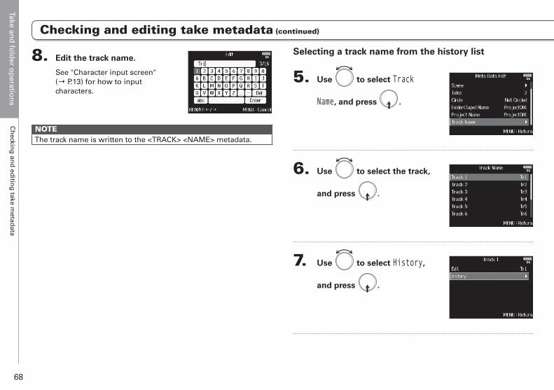
Take and
fold
er op
eration
sC
heckin
g an
d ed
iting
take metad
ata
68
Checking and editing take metadata (continued)
Selecting a track name from the history list
5. Use to select Track
Name, and press .
6. Use to select the track,
and press .
7. Use to select History,
and press .
8. Edit the track name.
See "Character input screen" (→ P.13) for how to input characters.
NOTEThe track name is written to the <TRACK> <NAME> metadata.
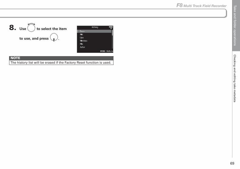
Take and
fold
er op
eration
sC
heckin
g an
d ed
iting
take metad
ata
69
F8 Multi Track Field Recorder
Checking and editing take metadata (continued)
8. Use to select the item
to use, and press .
NOTEThe history list will be erased if the Factory Reset function is used.
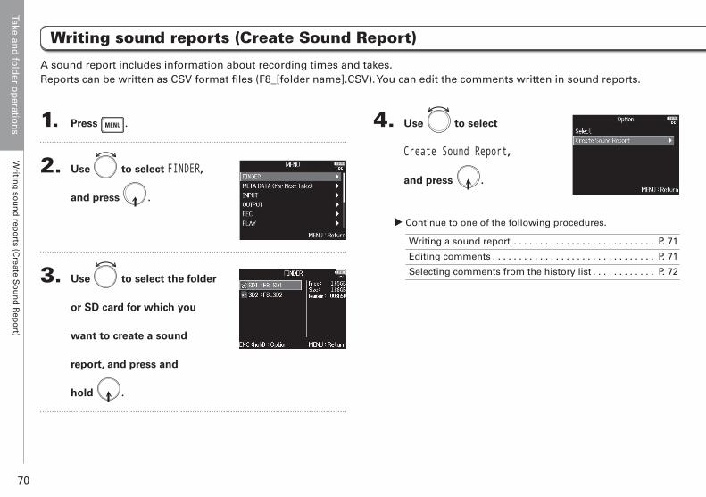
Take and
fold
er op
eration
sW
riting
sou
nd
repo
rts (Create S
ou
nd
Rep
ort)
70
Writing sound reports (Create Sound Report) (continued)
A sound report includes information about recording times and takes. Reports can be written as CSV format files (F8_[folder name].CSV). You can edit the comments written in sound reports.
4. Use to select
Create Sound Report,
and press .
▶ Continue to one of the following procedures.
Writing a sound report . . . . . . . . . . . . . . . . . . . . . . . . . . . P. 71
Editing comments . . . . . . . . . . . . . . . . . . . . . . . . . . . . . . . P. 71
Selecting comments from the history list . . . . . . . . . . . . P. 72
Writing sound reports (Create Sound Report)
1. Press .
2. Use to select FINDER,
and press .
3. Use to select the folder
or SD card for which you
want to create a sound
report, and press and
hold .

Take and
fold
er op
eration
sW
riting
sou
nd
repo
rts (Create S
ou
nd
Rep
ort)
71
F8 Multi Track Field Recorder
Writing sound reports (Create Sound Report) (continued)
Writing a sound report
5. Use to select Create,
and press .
6. Use to select Yes,
and press .
This writes the sound report inside the selected SD card or folder.
NOTE• Only information about takes in the folder or SD card is written
in the sound report.
• If a sound report file with the same name already exists, it will be
overwritten. Please use caution.
Editing comments
5. Use to select Info Edit,
and press .
6. Use to select Comments,
and press .
7. Use to select Edit,
and press .
8. Edit the comment.
See "Character input screen" (→ P.13) for how to input characters.
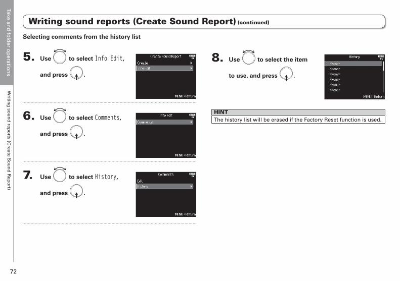
Take and
fold
er op
eration
sW
riting
sou
nd
repo
rts (Create S
ou
nd
Rep
ort)
72
Writing sound reports (Create Sound Report) (continued)
8. Use to select the item
to use, and press .
HINTThe history list will be erased if the Factory Reset function is used.
Selecting comments from the history list
5. Use to select Info Edit,
and press .
6. Use to select Comments,
and press .
7. Use to select History,
and press .
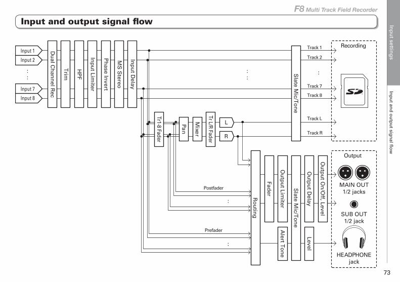
Inp
ut settin
gs
Inp
ut an
d o
utp
ut sig
nal fl
ow
73
F8 Multi Track Field Recorder
Input settings
Input and output signal flow
MAIN OUT1/2 jacks
SUB OUT1/2 jack
HEADPHONEjack
Recording
Output
Input 1
::
Trim
HP
F
Inp
ut Lim
iter
Ph
ase Invert
MS
Stereo
Inp
ut D
elay
Tr1-8 Fader
Mixe
r
L
R
Ou
tpu
t Delay
Level
Slate M
ic/To
ne
Ou
tpu
t Limiter
Fader
Alert T
on
e
Slate M
ic/To
ne
Tr L/R Fader
Ro
utin
g
::
:
:
Ou
tpu
t On
/Off, Level
Pan
Du
al Ch
ann
el Rec
Input 2
Input 7
Input 8
Track 1
Track 2
Track 7
Track L
Track R
Postfader
Prefader
Track 8
:
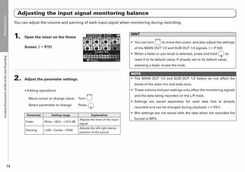
Inp
ut settin
gs
Ad
justin
g th
e inp
ut sig
nal m
on
itorin
g b
alance
74
Adjusting the input signal monitoring balance
1. Open the mixer on the Home
Screen. (→ P.11)
2. Adjust the parameter settings.
■ Editing operations
Move cursor or change value: Turn
Select parameter to change: Press
Parameter Setting range Explanation
Fader Mute, −48.0 – +12.0 dBAdjusts the level of the input signal.
Panning L100 – Center – R100Adjusts the left-right stereo position of the sound.
HINT
• You can turn to move the cursor, and also adjust the settings
of the MAIN OUT 1/2 and SUB OUT 1/2 signals. (→ P.102)
• When a fader or pan knob is selected, press and hold to
reset it to its default value. If already set to its default value,
selecting a fader mutes the track.
NOTE• The MAIN OUT 1/2 and SUB OUT 1/2 faders do not affect the
levels of the slate mic and slate tone.
• These volume and pan settings only affect the monitoring signals
and the data being recorded on the L/R track.
• Settings are saved separately for each take that is already
recorded and can be changed during playback. (→ P.51)
• Mix settings are not saved with the take when the recorded file
format is MP3.
You can adjust the volume and panning of each input signal when monitoring during recording.
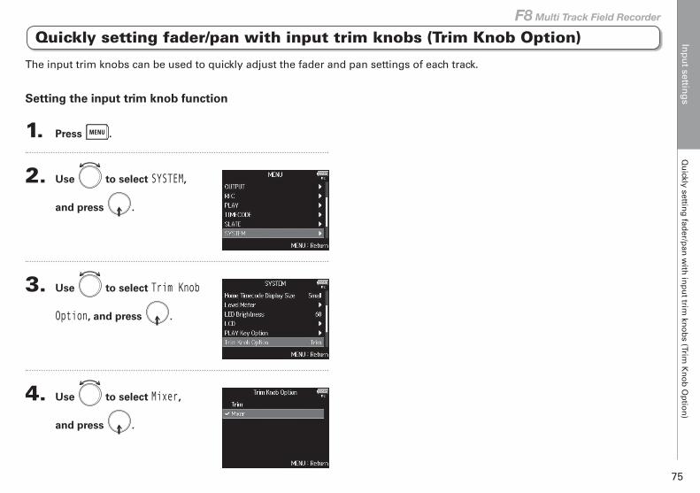
Inp
ut settin
gs
Qu
ickly setting
fader/p
an w
ith in
pu
t trim kn
ob
s (Trim K
no
b O
ptio
n)
75
F8 Multi Track Field Recorder
Setting the input trim knob function
1. Press .
2. Use to select SYSTEM,
and press .
3. Use to select Trim Knob
Option, and press .
4. Use to select Mixer,
and press .
Quickly setting fader/pan with input trim knobs (Trim Knob Option)
The input trim knobs can be used to quickly adjust the fader and pan settings of each track.
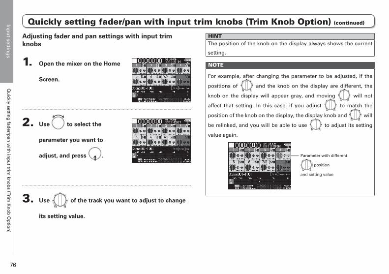
Inp
ut settin
gs
Qu
ickly setting
fader/p
an w
ith in
pu
t trim kn
ob
s (Trim K
no
b O
ptio
n)
76
Adjusting fader and pan settings with input trim knobs
1. Open the mixer on the Home
Screen.
2. Use to select the
parameter you want to
adjust, and press .
3. Use of the track you want to adjust to change
its setting value.
HINTThe position of the knob on the display always shows the current
setting.
NOTE
For example, after changing the parameter to be adjusted, if the
positions of and the knob on the display are different, the
knob on the display will appear gray, and moving will not
affect that setting. In this case, if you adjust to match the
position of the knob on the display, the display knob and will
be relinked, and you will be able to use to adjust its setting
value again.
Parameter with different
position
and setting value
Quickly setting fader/pan with input trim knobs (Trim Knob Option) (continued)
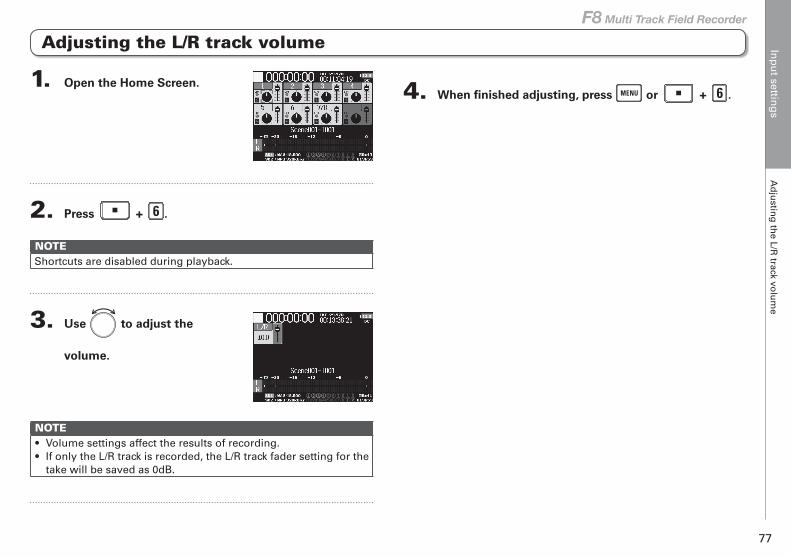
Inp
ut settin
gs
Ad
justin
g th
e L/R track vo
lum
e
77
F8 Multi Track Field Recorder
Adjusting the L/R track volume
4. When finished adjusting, press or + .1. Open the Home Screen.
2. Press + .
NOTEShortcuts are disabled during playback.
3. Use to adjust the
volume.
NOTE• Volume settings affect the results of recording.• If only the L/R track is recorded, the L/R track fader setting for the
take will be saved as 0dB.
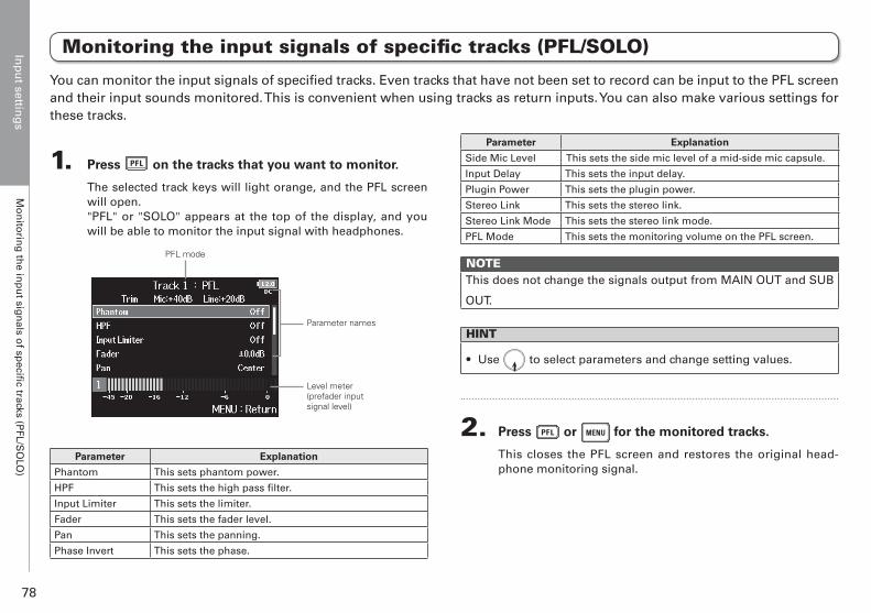
Inp
ut settin
gs
Mo
nito
ring
the in
pu
t sign
als of sp
ecific tracks (P
FL/SO
LO)
78
Monitoring the input signals of specific tracks (PFL/SOLO)
1. Press on the tracks that you want to monitor.
The selected track keys will light orange, and the PFL screen will open."PFL" or "SOLO" appears at the top of the display, and you will be able to monitor the input signal with headphones.
PFL mode
Level meter(prefader input signal level)
Parameter names
Parameter Explanation
Phantom This sets phantom power.
HPF This sets the high pass filter.
Input Limiter This sets the limiter.
Fader This sets the fader level.
Pan This sets the panning.
Phase Invert This sets the phase.
Parameter Explanation
Side Mic Level This sets the side mic level of a mid-side mic capsule.
Input Delay This sets the input delay.
Plugin Power This sets the plugin power.
Stereo Link This sets the stereo link.
Stereo Link Mode This sets the stereo link mode.
PFL Mode This sets the monitoring volume on the PFL screen.
NOTEThis does not change the signals output from MAIN OUT and SUB
OUT.
HINT
• Use to select parameters and change setting values.
2. Press or for the monitored tracks.
This closes the PFL screen and restores the original head-phone monitoring signal.
You can monitor the input signals of specified tracks. Even tracks that have not been set to record can be input to the PFL screen and their input sounds monitored. This is convenient when using tracks as return inputs. You can also make various settings for these tracks.
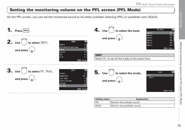
Inp
ut settin
gs
Settin
g th
e mo
nito
ring
volu
me o
n th
e PFL screen
(PFL M
od
e)
79
F8 Multi Track Field Recorder
1. Press .
2. Use to select INPUT,
and press .
3. Use to select PFL Mode,
and press .
4. Use to select the track,
and press .
HINTSelect ALL to set all the tracks at the same time.
5. Use to select the mode,
and press .
Setting value Explanation
PFL Monitor the prefader sound.
SOLO Monitor the postfader sound.
Setting the monitoring volume on the PFL screen (PFL Mode)
On the PFL screen, you can set the monitored sound to be either prefader listening (PFL) or postfader solo (SOLO).
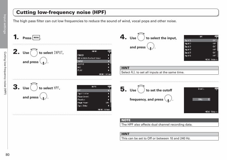
Inp
ut settin
gs
Cu
tting
low
-frequ
ency n
oise (H
PF)
80
Cutting low-frequency noise (HPF)
1. Press .
2. Use to select INPUT,
and press .
3. Use to select HPF,
and press .
4. Use to select the input,
and press .
HINTSelect ALL to set all inputs at the same time.
5. Use to set the cutoff
frequency, and press .
NOTEThe HPF also affects dual channel recording data.
HINTThis can be set to Off or between 10 and 240 Hz.
The high pass filter can cut low frequencies to reduce the sound of wind, vocal pops and other noise.
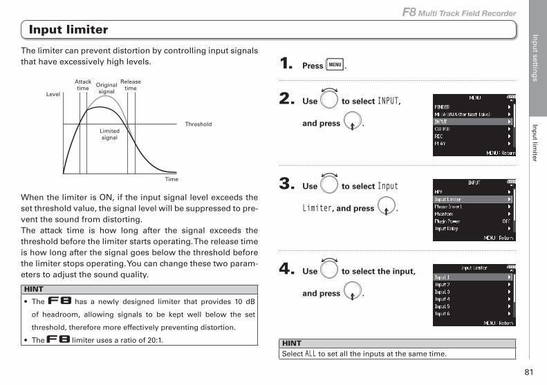
Inp
ut settin
gs
Inp
ut lim
iter
81
F8 Multi Track Field Recorder
The limiter can prevent distortion by controlling input signals that have excessively high levels.
Threshold
Level
Originalsignal
Limitedsignal
Attacktime
Releasetime
Time
When the limiter is ON, if the input signal level exceeds the set threshold value, the signal level will be suppressed to pre-vent the sound from distorting. The attack time is how long after the signal exceeds the threshold before the limiter starts operating. The release time is how long after the signal goes below the threshold before the limiter stops operating. You can change these two param-eters to adjust the sound quality.
HINT
• The has a newly designed limiter that provides 10 dB
of headroom, allowing signals to be kept well below the set
threshold, therefore more effectively preventing distortion.
• The limiter uses a ratio of 20:1.
1. Press .
2. Use to select INPUT,
and press .
3. Use to select Input
Limiter, and press .
4. Use to select the input,
and press .
HINTSelect ALL to set all the inputs at the same time.
Input limiter
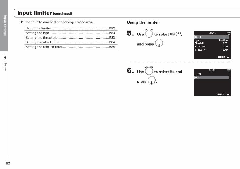
Inp
ut settin
gs
Inp
ut lim
iter
82
Using the limiter
5. Use to select On/Off,
and press .
6. Use to select On, and
press .
▶ Continue to one of the following procedures.
Using the limiter ................................................................P.82Setting the type .................................................................P.83Setting the threshold .........................................................P.83Setting the attack time.......................................................P.84Setting the release time ....................................................P.84
Input limiter (continued)
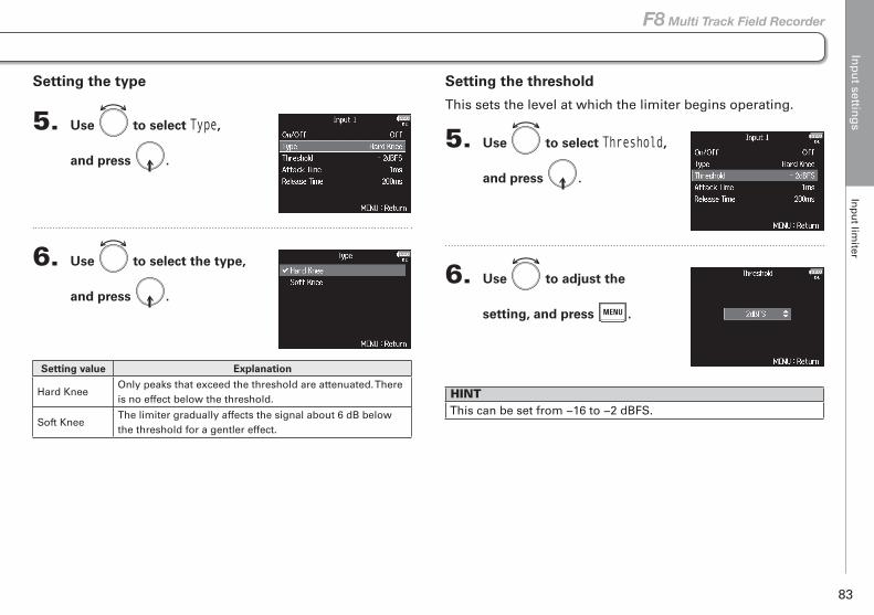
Inp
ut settin
gs
Inp
ut lim
iter
83
F8 Multi Track Field Recorder
Setting the threshold
This sets the level at which the limiter begins operating.
5. Use to select Threshold,
and press .
6. Use to adjust the
setting, and press .
HINTThis can be set from −16 to −2 dBFS.
Setting the type
5. Use to select Type,
and press .
6. Use to select the type,
and press .
Setting value Explanation
Hard KneeOnly peaks that exceed the threshold are attenuated. There is no effect below the threshold.
Soft KneeThe limiter gradually affects the signal about 6 dB below the threshold for a gentler effect.
Input limiter (continued)
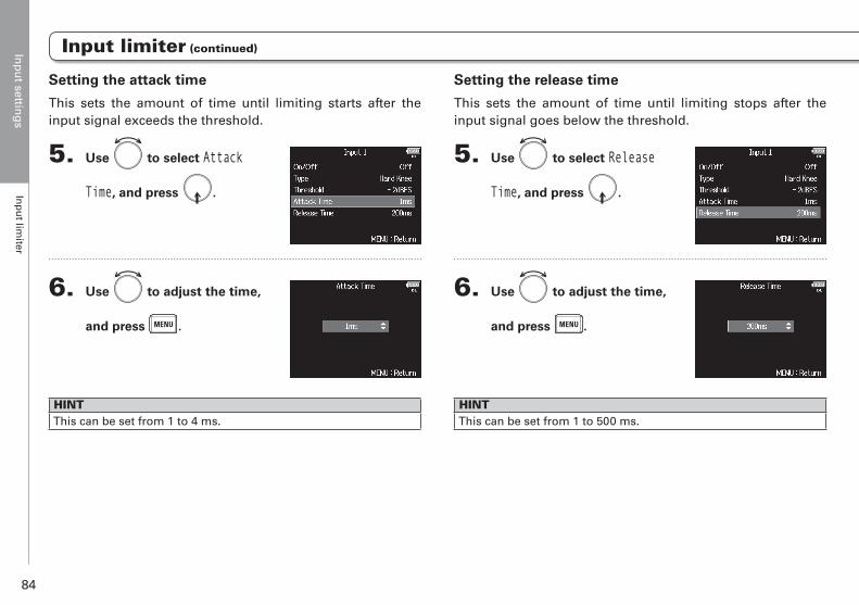
Inp
ut settin
gs
Inp
ut lim
iter
84
Setting the release time
This sets the amount of time until limiting stops after the input signal goes below the threshold.
5. Use to select Release
Time, and press .
6. Use to adjust the time,
and press .
HINTThis can be set from 1 to 500 ms.
Setting the attack time
This sets the amount of time until limiting starts after the input signal exceeds the threshold.
5. Use to select Attack
Time, and press .
6. Use to adjust the time,
and press .
HINTThis can be set from 1 to 4 ms.
Input limiter (continued)
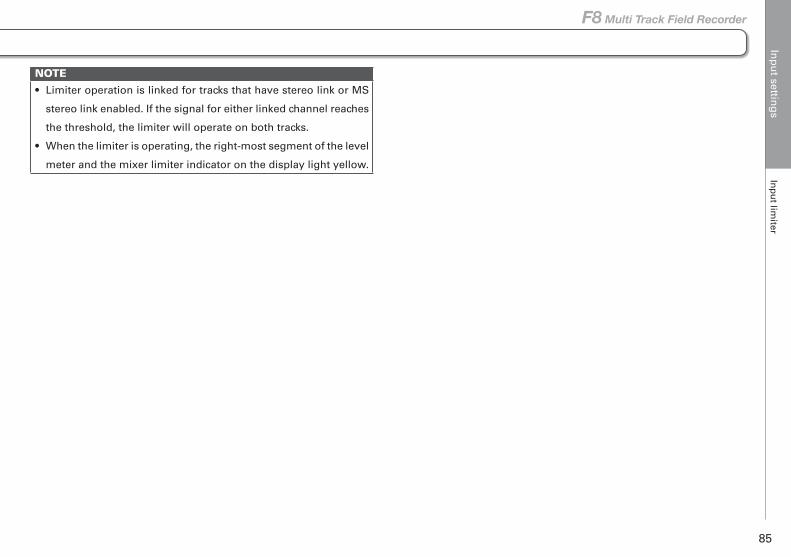
Inp
ut settin
gs
Inp
ut lim
iter
85
F8 Multi Track Field Recorder
NOTE
• Limiter operation is linked for tracks that have stereo link or MS
stereo link enabled. If the signal for either linked channel reaches
the threshold, the limiter will operate on both tracks.
• When the limiter is operating, the right-most segment of the level
meter and the mixer limiter indicator on the display light yellow.
Input limiter (continued)
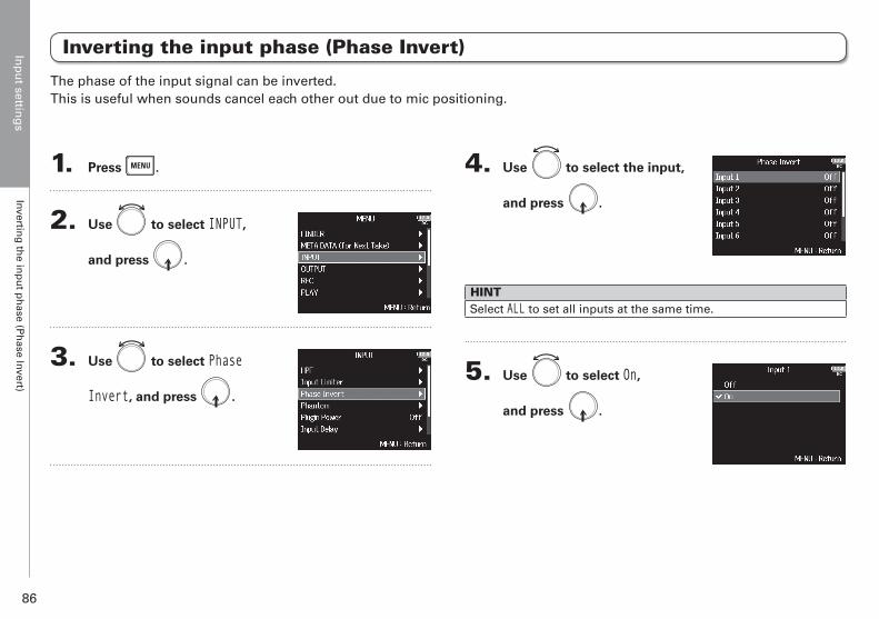
Inp
ut settin
gs
Inverting
the in
pu
t ph
ase (Ph
ase Invert)
86
Inverting the input phase (Phase Invert)
1. Press .
2. Use to select INPUT,
and press .
3. Use to select Phase
Invert, and press .
4. Use to select the input,
and press .
HINTSelect ALL to set all inputs at the same time.
5. Use to select On,
and press .
The phase of the input signal can be inverted.This is useful when sounds cancel each other out due to mic positioning.
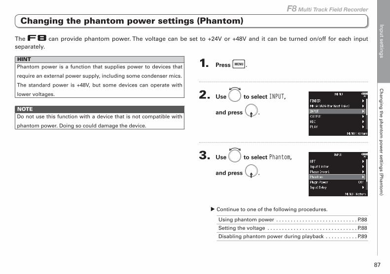
Inp
ut settin
gs
Ch
ang
ing
the p
han
tom
po
wer settin
gs (P
han
tom
)
87
F8 Multi Track Field Recorder
Changing the phantom power settings (Phantom)
HINTPhantom power is a function that supplies power to devices that
require an external power supply, including some condenser mics.
The standard power is +48V, but some devices can operate with
lower voltages.
NOTEDo not use this function with a device that is not compatible with
phantom power. Doing so could damage the device.
1. Press .
2. Use to select INPUT,
and press .
3. Use to select Phantom,
and press .
▶ Continue to one of the following procedures.
Using phantom power . . . . . . . . . . . . . . . . . . . . . . . . . . . . P.88
Setting the voltage . . . . . . . . . . . . . . . . . . . . . . . . . . . . . . . P.88
Disabling phantom power during playback . . . . . . . . . . . P.89
The can provide phantom power. The voltage can be set to +24V or +48V and it can be turned on/off for each input separately.
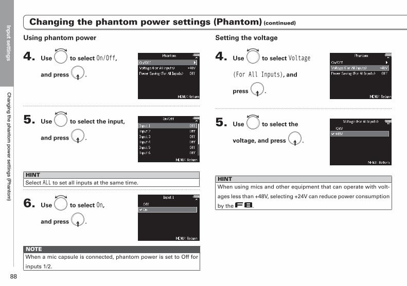
Input settingsC
hanging the phantom pow
er settings (Phantom)
88
Setting the voltage
4. Use to select Voltage
(For All Inputs), and
press .
5. Use to select the
voltage, and press .
HINTWhen using mics and other equipment that can operate with volt-
ages less than +48V, selecting +24V can reduce power consumption
by the .
Using phantom power
4. Use to select On/Off,
and press .
5. Use to select the input,
and press .
HINTSelect ALL to set all inputs at the same time.
6. Use to select On,
and press .
NOTEWhen a mic capsule is connected, phantom power is set to Off for
inputs 1/2.
Changing the phantom power settings (Phantom) (continued)
Changing the phantom power settings (Phantom)
Changing the phantom power settings (Phantom) (continued)
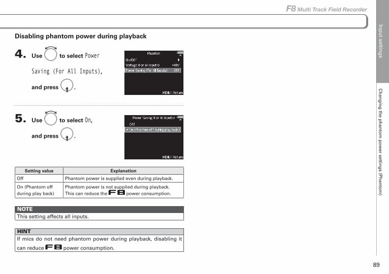
Changing the phantom power settings (Phantom) (continued)Changing the phantom power settings (Phantom) (continued) Inp
ut settin
gs
Ch
ang
ing
the p
han
tom
po
wer settin
gs (P
han
tom
)
89
F8 Multi Track Field Recorder
Disabling phantom power during playback
4. Use to select Power
Saving (For All Inputs),
and press .
5. Use to select On,
and press .
Setting value Explanation
Off Phantom power is supplied even during playback.
On (Phantom off during play back)
Phantom power is not supplied during playback.This can reduce the power consumption.
NOTEThis setting affects all inputs.
HINTIf mics do not need phantom power during playback, disabling it
can reduce power consumption.
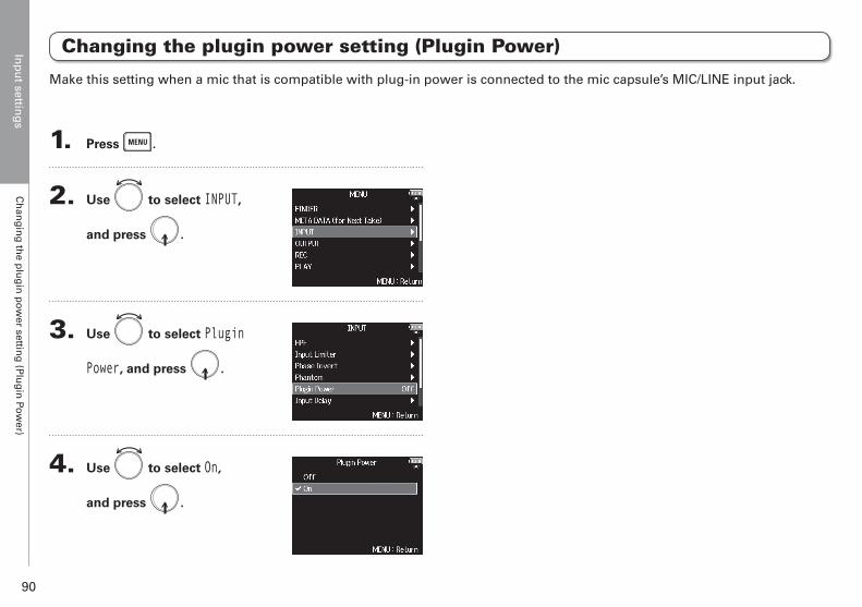
Inp
ut settin
gs
Ch
ang
ing
the p
lug
in p
ow
er setting
(Plu
gin
Pow
er)
90
Changing the plugin power setting (Plugin Power)
1. Press .
2. Use to select INPUT,
and press .
3. Use to select Plugin
Power, and press .
4. Use to select On,
and press .
Make this setting when a mic that is compatible with plug-in power is connected to the mic capsule’s MIC/LINE input jack.
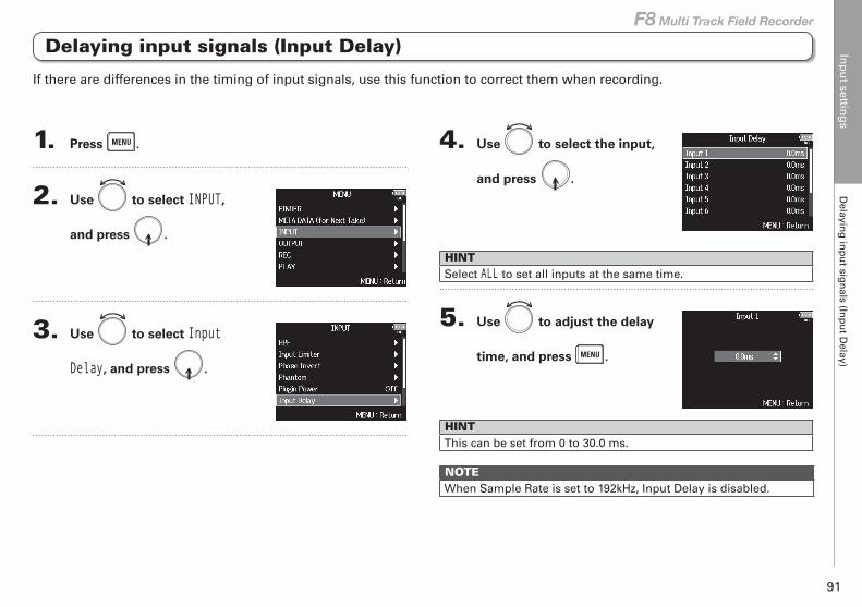
Inp
ut settin
gs
Delayin
g in
pu
t sign
als (Inp
ut D
elay)
91
F8 Multi Track Field Recorder
Delaying input signals (Input Delay)
1. Press .
2. Use to select INPUT,
and press .
3. Use to select Input
Delay, and press .
4. Use to select the input,
and press .
HINTSelect ALL to set all inputs at the same time.
5. Use to adjust the delay
time, and press .
HINTThis can be set from 0 to 30.0 ms.
NOTEWhen Sample Rate is set to 192kHz, Input Delay is disabled.
If there are differences in the timing of input signals, use this function to correct them when recording.
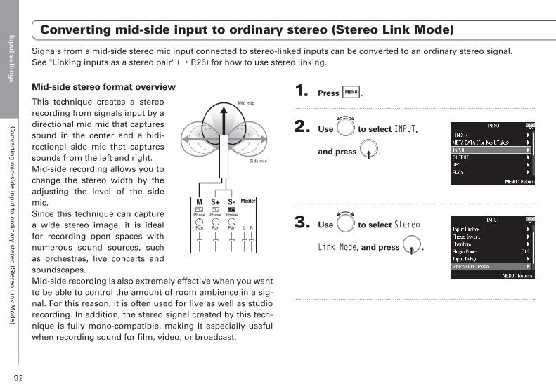
Inp
ut settin
gs
Co
nverting
mid
-side in
pu
t to o
rdin
ary stereo (S
tereo Lin
k Mo
de)
92
Converting mid-side input to ordinary stereo (Stereo Link Mode)
Mid-side stereo format overview
This technique creates a stereo recording from signals input by a directional mid mic that captures sound in the center and a bidi-rectional side mic that captures sounds from the left and right.Mid-side recording allows you to change the stereo width by the adjusting the level of the side mic. Since this technique can capture a wide stereo image, it is ideal for recording open spaces with numerous sound sources, such as orchestras, live concerts and soundscapes.Mid-side recording is also extremely effective when you want to be able to control the amount of room ambience in a sig-nal. For this reason, it is often used for live as well as studio recording. In addition, the stereo signal created by this tech-nique is fully mono-compatible, making it especially useful when recording sound for film, video, or broadcast.
1. Press .
2. Use to select INPUT,
and press .
3. Use to select Stereo
Link Mode, and press .
Signals from a mid-side stereo mic input connected to stereo-linked inputs can be converted to an ordinary stereo signal. See "Linking inputs as a stereo pair" (→ P.26) for how to use stereo linking.
Mid mic
Side mic
Phase
S+ Master
Pan
Phase
S-
Pan
Phase
M
Pan L R
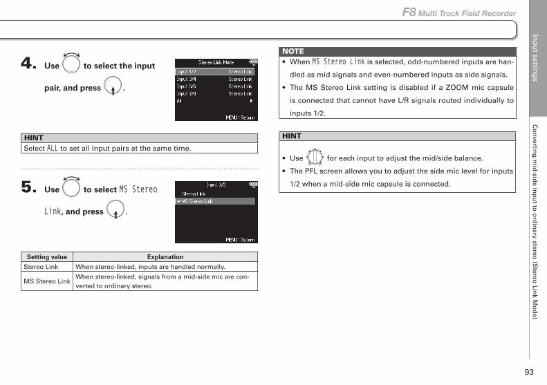
Inp
ut settin
gs
Co
nverting
mid
-side in
pu
t to o
rdin
ary stereo (S
tereo Lin
k Mo
de)
93
F8 Multi Track Field Recorder
Converting mid-side input to ordinary stereo (Stereo Link Mode)
4. Use to select the input
pair, and press .
HINTSelect ALL to set all input pairs at the same time.
5. Use to select MS Stereo
Link, and press .
Setting value Explanation
Stereo Link When stereo-linked, inputs are handled normally.
MS Stereo LinkWhen stereo-linked, signals from a mid-side mic are con-verted to ordinary stereo.
NOTE• When MS Stereo Link is selected, odd-numbered inputs are han-
dled as mid signals and even-numbered inputs as side signals.
• The MS Stereo Link setting is disabled if a ZOOM mic capsule
is connected that cannot have L/R signals routed individually to
inputs 1/2.
HINT
• Use for each input to adjust the mid/side balance.
• The PFL screen allows you to adjust the side mic level for inputs
1/2 when a mid-side mic capsule is connected.
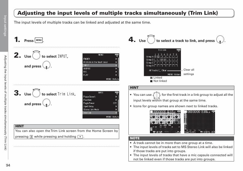
Inp
ut settin
gs
Ad
justin
g th
e inp
ut levels o
f mu
ltiple tracks sim
ultan
eou
sly (Trim Lin
k)
94
Adjusting the input levels of multiple tracks simultaneously (Trim Link)
1. Press .
2. Use to select INPUT,
and press .
3. Use to select Trim Link,
and press .
HINTYou can also open the Trim Link screen from the Home Screen by
pressing while pressing and holding .
4. Use to select a track to link, and press .
Clear all
settingsLinkedNot linked
HINT
• You can use for the first track in a link group to adjust all the
input levels within that group at the same time.
• Icons for group names are shown next to linked tracks.
NOTE• A track cannot be in more than one group at a time.• The input levels of tracks set to MS Stereo Link will also be linked
if those tracks are put into groups.• The input levels of tracks that have a mic capsule connected will
not be linked even if those tracks are put into groups.
The input levels of multiple tracks can be linked and adjusted at the same time.
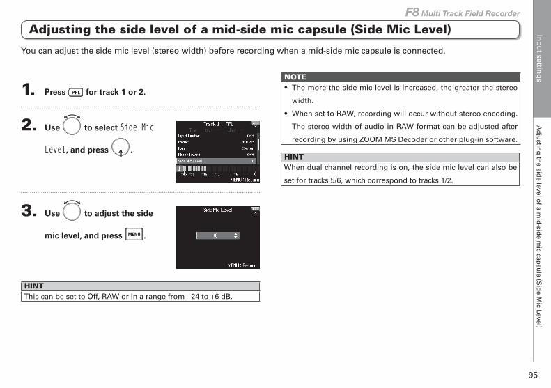
Inp
ut settin
gs
Ad
justin
g th
e side level o
f a mid
-side m
ic capsu
le (Sid
e Mic Level)
95
F8 Multi Track Field Recorder
Adjusting the side level of a mid-side mic capsule (Side Mic Level)
1. Press for track 1 or 2.
2. Use to select Side Mic
Level, and press .
3. Use to adjust the side
mic level, and press .
HINTThis can be set to Off, RAW or in a range from −24 to +6 dB.
NOTE• The more the side mic level is increased, the greater the stereo
width.
• When set to RAW, recording will occur without stereo encoding.
The stereo width of audio in RAW format can be adjusted after
recording by using ZOOM MS Decoder or other plug-in software.
HINTWhen dual channel recording is on, the side mic level can also be
set for tracks 5/6, which correspond to tracks 1/2.
You can adjust the side mic level (stereo width) before recording when a mid-side mic capsule is connected.
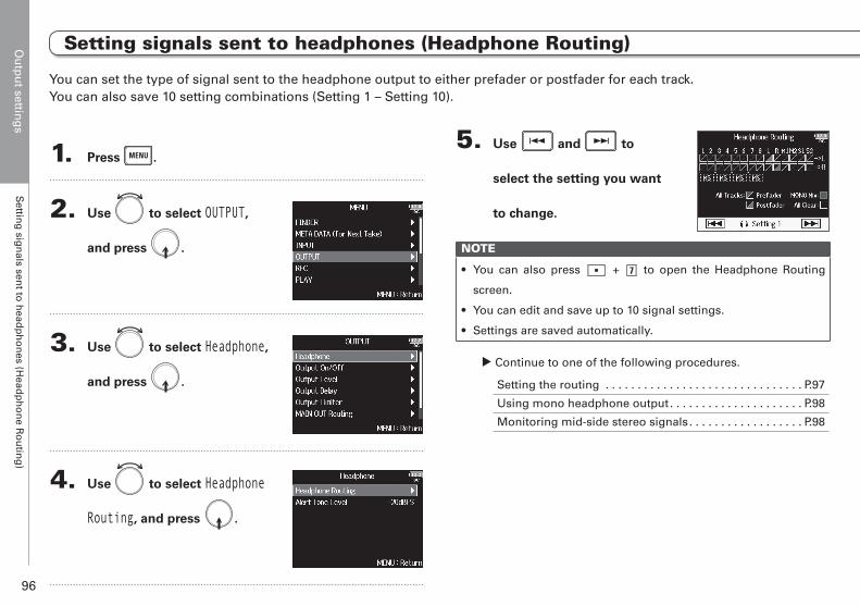
Ou
tpu
t setting
sS
etting
sign
als sent to
head
ph
on
es (Head
ph
on
e Ro
utin
g)
96
1. Press .
2. Use to select OUTPUT,
and press .
3. Use to select Headphone,
and press .
4. Use to select Headphone
Routing, and press .
5. Use and to
select the setting you want
to change.
NOTE
• You can also press + to open the Headphone Routing
screen.
• You can edit and save up to 10 signal settings.
• Settings are saved automatically.
▶ Continue to one of the following procedures.
Setting the routing . . . . . . . . . . . . . . . . . . . . . . . . . . . . . . . P.97
Using mono headphone output. . . . . . . . . . . . . . . . . . . . . P.98
Monitoring mid-side stereo signals. . . . . . . . . . . . . . . . . . P.98
You can set the type of signal sent to the headphone output to either prefader or postfader for each track. You can also save 10 setting combinations (Setting 1 – Setting 10).
Output settings
Setting signals sent to headphones (Headphone Routing)
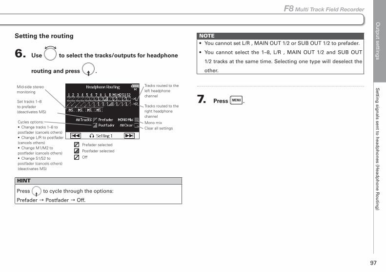
Ou
tpu
t setting
sS
etting
sign
als sent to
head
ph
on
es (Head
ph
on
e Ro
utin
g)
97
F8 Multi Track Field Recorder
Setting signals sent to headphones (Headphone Routing)
Setting the routing
6. Use to select the tracks/outputs for headphone
routing and press .
Clear all settingsMono mix
Tracks routed to the left headphone channel
Tracks routed to the right headphone channel
Set tracks 1–8 to prefader (deactivates MS)
Mid-side stereo monitoring
Cycles options:• Change tracks 1–8 to postfader (cancels others)• Change L/R to postfader (cancels others)• Change M1/M2 to postfader (cancels others)• Change S1/S2 to postfader (cancels others) (deactivates MS)
Prefader selected
Postfader selected
Off
HINT
Press to cycle through the options:
Prefader → Postfader → Off.
NOTE• You cannot set L/R , MAIN OUT 1/2 or SUB OUT 1/2 to prefader.
• You cannot select the 1–8, L/R , MAIN OUT 1/2 and SUB OUT
1/2 tracks at the same time. Selecting one type will deselect the
other.
7. Press .
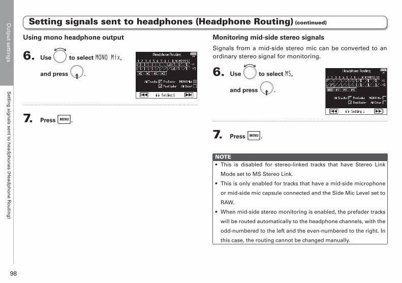
Ou
tpu
t setting
sS
etting
sign
als sent to
head
ph
on
es (Head
ph
on
e Ro
utin
g)
98
Using mono headphone output
6. Use to select MONO Mix,
and press .
7. Press .
Setting signals sent to headphones (Headphone Routing) (continued)
Monitoring mid-side stereo signals
Signals from a mid-side stereo mic can be converted to an ordinary stereo signal for monitoring.
6. Use to select MS,
and press .
7. Press .
NOTE• This is disabled for stereo-linked tracks that have Stereo Link
Mode set to MS Stereo Link.
• This is only enabled for tracks that have a mid-side microphone
or mid-side mic capsule connected and the Side Mic Level set to
RAW.
• When mid-side stereo monitoring is enabled, the prefader tracks
will be routed automatically to the headphone channels, with the
odd-numbered to the left and the even-numbered to the right. In
this case, the routing cannot be changed manually.
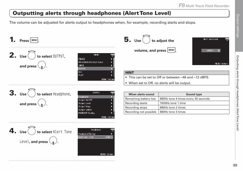
Ou
tpu
t setting
sO
utp
uttin
g alerts th
rou
gh
head
ph
on
es (Alert To
ne Level)
99
F8 Multi Track Field Recorder
Outputting alerts through headphones (Alert Tone Level)
1. Press .
2. Use to select OUTPUT,
and press .
3. Use to select Headphone,
and press .
4. Use to select Alert Tone
Level, and press .
5. Use to adjust the
volume, and press .
HINT• This can be set to Off or between −48 and −12 dBFS.
• When set to Off, no alerts will be output.
When alerts sound Sound type
Remaining battery low 880Hz tone 4 times every 30 seconds
Recording starts 1000Hz tone 1 time
Recording stops 880Hz tone 2 times
Recording not possible 880Hz tone 3 times
The volume can be adjusted for alerts output to headphones when, for example, recording starts and stops.
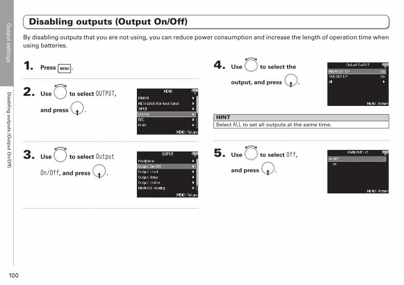
Ou
tpu
t setting
sD
isablin
g o
utp
uts (O
utp
ut O
n/O
ff)
100
1. Press .
2. Use to select OUTPUT,
and press .
3. Use to select Output
On/Off, and press .
4. Use to select the
output, and press .
HINTSelect ALL to set all outputs at the same time.
5. Use to select Off,
and press .
Disabling outputs (Output On/Off)
By disabling outputs that you are not using, you can reduce power consumption and increase the length of operation time when using batteries.
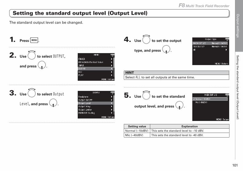
Ou
tpu
t setting
sS
etting
the stan
dard
ou
tpu
t level (Ou
tpu
t Level)
101
F8 Multi Track Field Recorder
Setting the standard output level (Output Level)
1. Press .
2. Use to select OUTPUT,
and press .
3. Use to select Output
Level, and press .
4. Use to set the output
type, and press .
HINTSelect ALL to set all outputs at the same time.
5. Use to set the standard
output level, and press .
Setting value Explanation
Normal (−10dBV) This sets the standard level to −10 dBV.
Mic (−40dBV) This sets the standard level to -40 dBV.
The standard output level can be changed.
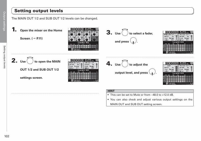
Ou
tpu
t setting
sS
etting
ou
tpu
t levels
102
1. Open the mixer on the Home
Screen. (→ P.11)
2. Use to open the MAIN
OUT 1/2 and SUB OUT 1/2
settings screen.
3. Use to select a fader,
and press .
4. Use to adjust the
output level, and press .
HINT• This can be set to Mute or from −48.0 to +12.0 dB.
• You can also check and adjust various output settings on the
MAIN OUT and SUB OUT setting screen.
Setting output levels
The MAIN OUT 1/2 and SUB OUT 1/2 levels can be changed.
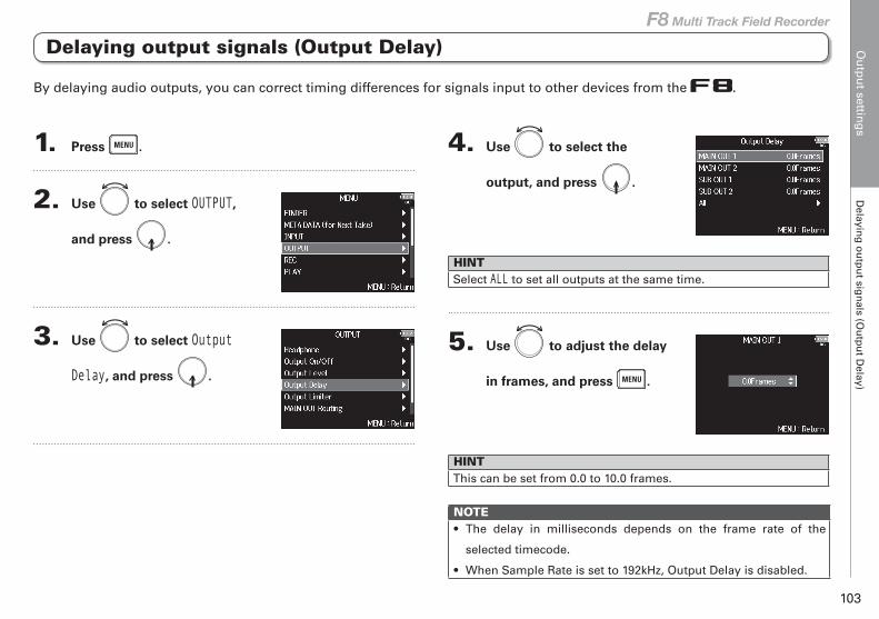
Ou
tpu
t setting
sD
elaying
ou
tpu
t sign
als (Ou
tpu
t Delay)
103
F8 Multi Track Field Recorder
Delaying output signals (Output Delay)
1. Press .
2. Use to select OUTPUT,
and press .
3. Use to select Output
Delay, and press .
4. Use to select the
output, and press .
HINTSelect ALL to set all outputs at the same time.
5. Use to adjust the delay
in frames, and press .
HINTThis can be set from 0.0 to 10.0 frames.
NOTE• The delay in milliseconds depends on the frame rate of the
selected timecode.
• When Sample Rate is set to 192kHz, Output Delay is disabled.
By delaying audio outputs, you can correct timing differences for signals input to other devices from the .
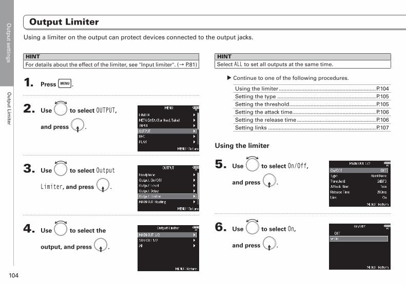
Ou
tpu
t setting
sO
utp
ut Lim
iter
104
Output Limiter
HINTFor details about the effect of the limiter, see "Input limiter". (→ P.81)
1. Press .
2. Use to select OUTPUT,
and press .
3. Use to select Output
Limiter, and press .
4. Use to select the
output, and press .
HINTSelect ALL to set all outputs at the same time.
▶ Continue to one of the following procedures.
Using the limiter ................................................................P.104Setting the type .................................................................P.105Setting the threshold .........................................................P.105Setting the attack time.......................................................P.106Setting the release time ....................................................P.106Setting links .......................................................................P.107
Using the limiter
5. Use to select On/Off,
and press .
6. Use to select On,
and press .
Using a limiter on the output can protect devices connected to the output jacks.

Ou
tpu
t setting
sO
utp
ut Lim
iter
105
F8 Multi Track Field Recorder
Output Limiter
Setting the type
5. Use to select Type,
and press .
6. Use to select the type,
and press .
Setting value Explanation
Hard KneeOnly peaks that exceed the threshold are attenuated. There is no effect below the threshold.
Soft KneeThe limiter gradually affects the output signal about 6 dB below the threshold for a gentler effect.
Setting the threshold
This sets the level at which the limiter begins operating.
5. Use to select Threshold,
and press .
6. Use to adjust the
setting, and press .
HINTThis can be set from −16 to −2 dBFS.
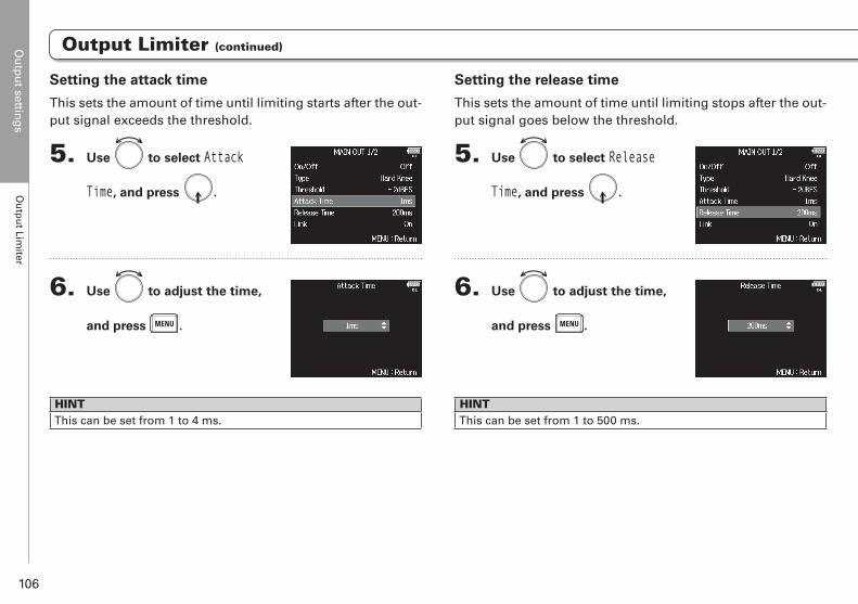
Ou
tpu
t setting
sO
utp
ut Lim
iter
106
Output Limiter (continued)
Setting the release time
This sets the amount of time until limiting stops after the out-put signal goes below the threshold.
5. Use to select Release
Time, and press .
6. Use to adjust the time,
and press .
HINTThis can be set from 1 to 500 ms.
Setting the attack time
This sets the amount of time until limiting starts after the out-put signal exceeds the threshold.
5. Use to select Attack
Time, and press .
6. Use to adjust the time,
and press .
HINTThis can be set from 1 to 4 ms.
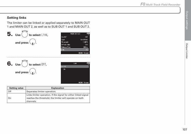
Ou
tpu
t setting
sO
utp
ut Lim
iter
107
F8 Multi Track Field Recorder
Output Limiter (continued)
Setting links
The limiter can be linked or applied separately to MAIN OUT 1 and MAIN OUT 2, as well as to SUB OUT 1 and SUB OUT 2.
5. Use to select Link,
and press .
6. Use to select Off,
and press .
Setting value Explanation
Off Separates limiter operation.
OnLinks limiter operation. If the signal for either linked signal reaches the threshold, the limiter will operate on both channels.
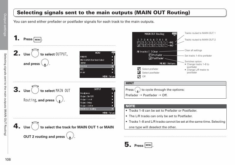
Ou
tpu
t setting
sS
electing
sign
als sent to
the m
ain o
utp
uts (M
AIN
OU
T R
ou
ting
)
108
Selecting signals sent to the main outputs (MAIN OUT Routing)
1. Press .
2. Use to select OUTPUT,
and press .
3. Use to select MAIN OUT
Routing, and press .
4. Use to select the track for MAIN OUT 1 or MAIN
OUT 2 routing and press .
Clear all settings
Tracks routed to MAIN OUT 1
Tracks routed to MAIN OUT 2
Set tracks 1–8 to prefader
Switches option:• Change tracks 1–8 to
postfader• Change L/R tracks to
postfaderSelect prefader
Select postfader
Off
HINT
Press to cycle through the options:
Prefader → Postfader → Off.
NOTE• Tracks 1–8 can be set to Prefader or Postfader.
• The L/R tracks can only be set to Postfader.
• Tracks 1–8 and L/R tracks cannot be set at the same time. Selecting
one type will deselect the other.
5. Press .
You can send either prefader or postfader signals for each track to the main outputs.
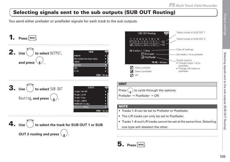
Ou
tpu
t setting
sS
electing
sign
als sent to
the su
b o
utp
uts (S
UB
OU
T R
ou
ting
)
109
F8 Multi Track Field Recorder
Selecting signals sent to the sub outputs (SUB OUT Routing)
1. Press .
2. Use to select OUTPUT,
and press .
3. Use to select SUB OUT
Routing, and press .
4. Use to select the track for SUB OUT 1 or SUB
OUT 2 routing and press .
Clear all settings
Tracks routed to SUB OUT 1
Tracks routed to SUB OUT 2
Set tracks 1–8 to prefader
Switch options:• Change tracks 1–8 to
postfader• Change L/R tracks to
postfaderSelect prefader
Select postfader
Off
HINT
Press to cycle through the options:
Prefader → Postfader → Off.
NOTE• Tracks 1–8 can be set to Prefader or Postfader.
• The L/R tracks can only be set to Postfader.
• Tracks 1–8 and L/R tracks cannot be set at the same time. Selecting
one type will deselect the other.
5. Press .
You send either prefader or postfader signals for each track to the sub outputs.
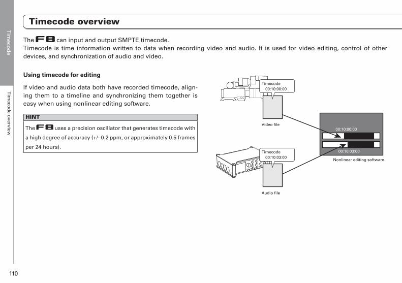
Tim
ecod
eT
imeco
de overview
110
Timecode overview
Timecode
Using timecode for editing
If video and audio data both have recorded timecode, align-ing them to a timeline and synchronizing them together is easy when using nonlinear editing software.
HINT
The uses a precision oscillator that generates timecode with
a high degree of accuracy (+/- 0.2 ppm, or approximately 0.5 frames
per 24 hours).
The can input and output SMPTE timecode. Timecode is time information written to data when recording video and audio. It is used for video editing, control of other devices, and synchronization of audio and video.
Nonlinear editing software
00:10:00:00
00:10:03:00
Audio file
Timecode00:10:03:00
Video file
Timecode00:10:00:00
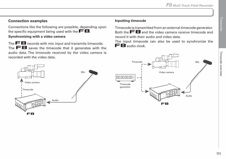
Tim
ecod
eT
imeco
de overview
111
F8 Multi Track Field Recorder
Timecode overview
Connection examples
Connections like the following are possible, depending upon the specific equipment being used with the .Synchronizing with a video camera
The records with mic input and transmits timecode.The saves the timecode that it generates with the audio data. The timecode received by the video camera is recorded with the video data.
Inputting timecode
Timecode is transmitted from an external timecode generator.Both the and the video camera receive timecode and record it with their audio and video data.The input timecode can also be used to synchronize the
audio clock.
Video camera
Timecode
Audio
Mic Video camera
Timecodegenerator
Timecode
Audio
Mic
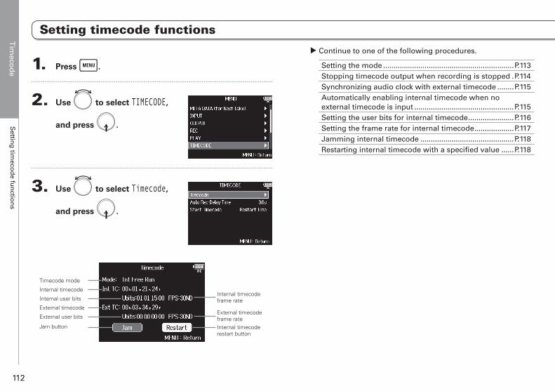
Tim
ecod
eS
etting
timeco
de fu
nctio
ns
112
Setting timecode functions
1. Press .
2. Use to select TIMECODE,
and press .
3. Use to select Timecode,
and press .
Internal timecodeframe rate
External timecodeframe rateInternal timecoderestart button
Timecode mode
Internal timecode
External timecode
Jam button
Internal user bits
External user bits
▶ Continue to one of the following procedures.
Setting the mode ...............................................................P.113Stopping timecode output when recording is stopped .P.114Synchronizing audio clock with external timecode ........P.115Automatically enabling internal timecode when no external timecode is input ................................................P.115Setting the user bits for internal timecode ......................P.116Setting the frame rate for internal timecode ...................P.117Jamming internal timecode .............................................P.118Restarting internal timecode with a specified value ......P.118
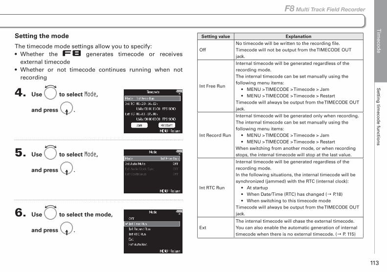
Tim
ecod
eS
etting
timeco
de fu
nctio
ns
113
F8 Multi Track Field Recorder
Setting timecode functions
Setting the mode
The timecode mode settings allow you to specify:• Whether the generates timecode or receives
external timecode• Whether or not timecode continues running when not
recording
4. Use to select Mode,
and press .
5. Use to select Mode,
and press .
6. Use to select the mode,
and press .
Setting value Explanation
OffNo timecode will be written to the recording file. Timecode will not be output from the TIMECODE OUT jack.
Int Free Run
Internal timecode will be generated regardless of the recording mode. The internal timecode can be set manually using the following menu items: • MENU > TIMECODE > Timecode > Jam • MENU > TIMECODE > Timecode > Restart Timecode will always be output from the TIMECODE OUT jack.
Int Record Run
Internal timecode will be generated only when recording. The internal timecode can be set manually using the following menu items: • MENU > TIMECODE > Timecode > Jam • MENU > TIMECODE > Timecode > Restart When switching from another mode, or when recording stops, the internal timecode will stop at the last value.
Int RTC Run
Internal timecode will be generated regardless of the recording mode. In the following situations, the internal timecode will be synchronized (jammed) with the RTC (internal clock): • At startup • When Date/Time (RTC) has changed (→ P.18) • When switching to this timecode mode Timecode will always be output from the TIMECODE OUT jack.
ExtThe internal timecode will chase the external timecode. You can also enable the automatic generation of internal timecode when there is no external timecode. (→ P. 115)
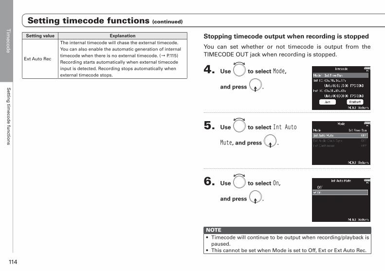
Tim
ecod
eS
etting
timeco
de fu
nctio
ns
114
Setting timecode functions (continued)
Setting value Explanation
Ext Auto Rec
The internal timecode will chase the external timecode. You can also enable the automatic generation of internal timecode when there is no external timecode. (→ P.115) Recording starts automatically when external timecode input is detected. Recording stops automatically when external timecode stops.
Stopping timecode output when recording is stopped
You can set whether or not timecode is output from the TIMECODE OUT jack when recording is stopped.
4. Use to select Mode,
and press .
5. Use to select Int Auto
Mute, and press .
6. Use to select On,
and press .
NOTE• Timecode will continue to be output when recording/playback is
paused.• This cannot be set when Mode is set to Off, Ext or Ext Auto Rec.
Setting timecode functions (continued)
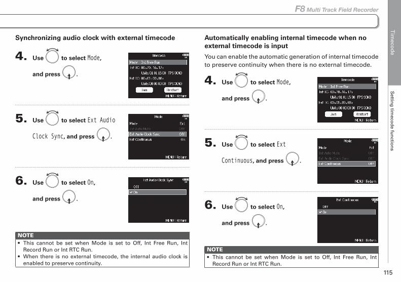
Tim
ecod
eS
etting
timeco
de fu
nctio
ns
115
F8 Multi Track Field Recorder
Setting timecode functions (continued)
Synchronizing audio clock with external timecode
4. Use to select Mode,
and press .
5. Use to select Ext Audio
Clock Sync, and press .
6. Use to select On,
and press .
NOTE• This cannot be set when Mode is set to Off, Int Free Run, Int
Record Run or Int RTC Run.• When there is no external timecode, the internal audio clock is
enabled to preserve continuity.
Automatically enabling internal timecode when no external timecode is input
You can enable the automatic generation of internal timecode to preserve continuity when there is no external timecode.
4. Use to select Mode,
and press .
5. Use to select Ext
Continuous, and press .
6. Use to select On,
and press .
NOTE• This cannot be set when Mode is set to Off, Int Free Run, Int
Record Run or Int RTC Run.
Setting timecode functions (continued)
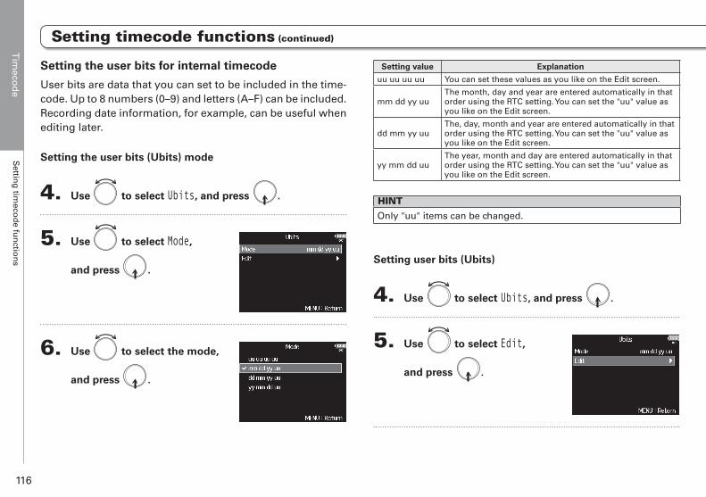
Tim
ecod
eS
etting
timeco
de fu
nctio
ns
116
Setting timecode functions (continued)
Setting value Explanation
uu uu uu uu You can set these values as you like on the Edit screen.
mm dd yy uuThe month, day and year are entered automatically in that order using the RTC setting. You can set the "uu" value as you like on the Edit screen.
dd mm yy uuThe, day, month and year are entered automatically in that order using the RTC setting. You can set the "uu" value as you like on the Edit screen.
yy mm dd uuThe year, month and day are entered automatically in that order using the RTC setting. You can set the "uu" value as you like on the Edit screen.
HINT
Only "uu" items can be changed.
Setting user bits (Ubits)
4. Use to select Ubits, and press .
5. Use to select Edit,
and press .
Setting the user bits for internal timecode
User bits are data that you can set to be included in the time-code. Up to 8 numbers (0–9) and letters (A–F) can be included. Recording date information, for example, can be useful when editing later.
Setting the user bits (Ubits) mode
4. Use to select Ubits, and press .
5. Use to select Mode,
and press .
6. Use to select the mode,
and press .
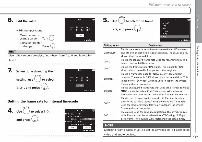
Tim
ecod
eS
etting
timeco
de fu
nctio
ns
117
F8 Multi Track Field Recorder
Setting timecode functions (continued)
5. Use to select the frame
rate, and press .
Setting value Explanation
23.976NDThis is the most common frame rate used with HD cameras and other high-definition video recording. The count is 0.1% slower than the actual time.
24NDThis is the standard frame rate used for recording film. This is also used with HD cameras.
25NDThis is the frame rate for PAL video. This is used for PAL video, which is used in Europe and other regions.
29.97ND
This is a frame rate used for NTSC color video and HD cameras. The count is 0.1% slower than the actual time. This is used for NTSC video, which is used in Japan, the United States and other countries.
29.97DThis is an adjusted frame rate that uses drop frames to make NTSC match the actual time. This is used with video for broadcast that requires the actual time frame to be matched.
30ND
This is used to synchronize sound with film that is being transferred to NTSC video. This is the standard frame rate used for black-and-white television in Japan, the United States and other countries.
30DThis rate is used for special applications. This synchronizes with film sound to be transferred to NTSC using 29.97fps drop frame. The count is 0.1% faster than the actual time.
NOTE
Matching frame rates must be set in advance on all connected
video and audio devices.
6. Edit the value.
■ Editing operations
Move cursor or change value: Turn
Select parameter to change: Press
HINTUser bits can only consist of numbers from 0 to 9 and letters from
A to F.
7. When done changing the
setting, use to select
Enter, and press .
Setting the frame rate for internal timecode
4. Use to select FPS,
and press .
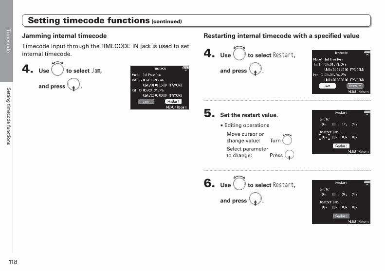
Tim
ecod
eS
etting
timeco
de fu
nctio
ns
118
Restarting internal timecode with a specified value
4. Use to select Restart,
and press .
5. Set the restart value.
■ Editing operations
Move cursor or change value: Turn
Select parameter to change: Press
6. Use to select Restart,
and press .
Jamming internal timecode
Timecode input through the TIMECODE IN jack is used to set internal timecode.
4. Use to select Jam,
and press .
Setting timecode functions (continued)

Tim
ecod
eS
etting
auto
matic tim
ecod
e record
ing
delay (A
uto
Rec D
elay Tim
e)
119
F8 Multi Track Field Recorder
Setting automatic timecode recording delay (Auto Rec Delay Time)
1. Press .
2. Use to select TIMECODE,
and press .
3. Use to select Auto Rec
Delay Time, and press .
4. Use to adjust the time,
and press .
HINTThis can be set from 0.0 to 8.0 s.
If set to record automatically when external timecode is received, unnecessary recording could occur when timecode is received for a brief amount time. In order to prevent this, you can set the amount of time until recording starts after timecode is received.
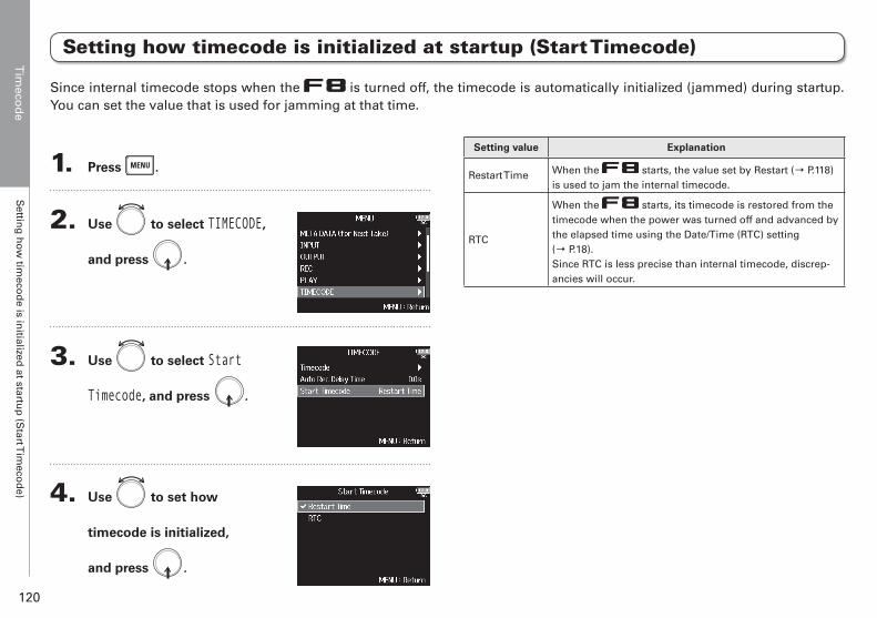
Tim
ecod
eS
etting
ho
w tim
ecod
e is initialized
at startup
(Start T
imeco
de)
120
Setting how timecode is initialized at startup (Start Timecode)
1. Press .
2. Use to select TIMECODE,
and press .
3. Use to select Start
Timecode, and press .
4. Use to set how
timecode is initialized,
and press .
Setting value Explanation
Restart Time When the starts, the value set by Restart (→ P.118) is used to jam the internal timecode.
RTC
When the starts, its timecode is restored from the timecode when the power was turned off and advanced by the elapsed time using the Date/Time (RTC) setting (→ P.18).Since RTC is less precise than internal timecode, discrep-ancies will occur.
Since internal timecode stops when the is turned off, the timecode is automatically initialized (jammed) during startup. You can set the value that is used for jamming at that time.
Slate m
ic/slate ton
e S
late mic an
d slate to
ne overview
121
F8 Multi Track Field Recorder
Slate mic and slate tone overview
Slate mic/slate tone
When recording with the , you can add audio com-ments that describe, for example, the scene being filmed or the anticipated cuts. You can also record slate tone signals that can be used to synchronize with video.The has a built-in slate mic for recording comments and the ability to output a variable frequency tone signal.
HINTA "slate" is a clapperboard used when recording video.
NOTE
• The slate mic and slate tone cannot be used at the same time.
• The slate mic and slate tone cannot be used during audio file
playback.
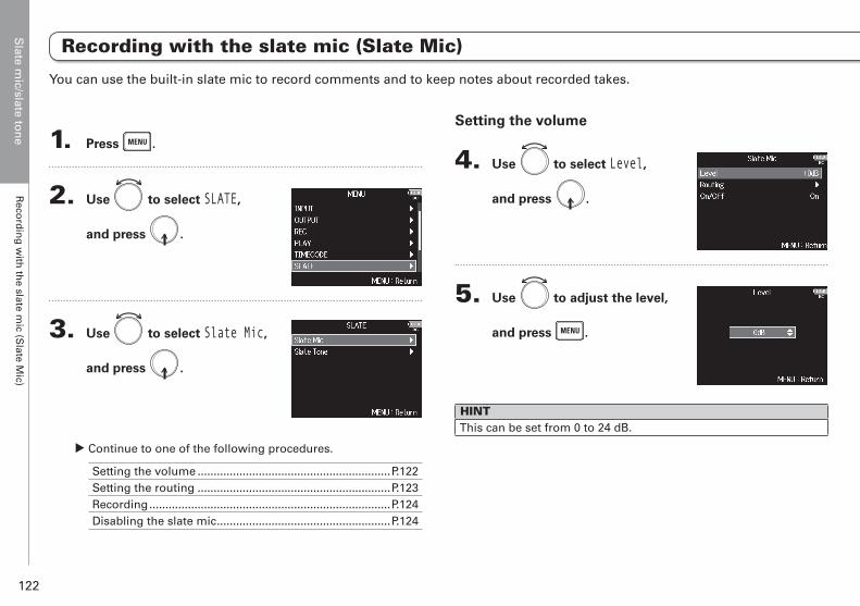
Slate m
ic/slate ton
e R
ecord
ing
with
the slate m
ic (Slate M
ic)
122
1. Press .
2. Use to select SLATE,
and press .
3. Use to select Slate Mic,
and press .
▶ Continue to one of the following procedures.
Setting the volume ............................................................P.122Setting the routing ............................................................P.123Recording ...........................................................................P.124Disabling the slate mic ......................................................P.124
Setting the volume
4. Use to select Level,
and press .
5. Use to adjust the level,
and press .
HINTThis can be set from 0 to 24 dB.
You can use the built-in slate mic to record comments and to keep notes about recorded takes.
Recording with the slate mic (Slate Mic)
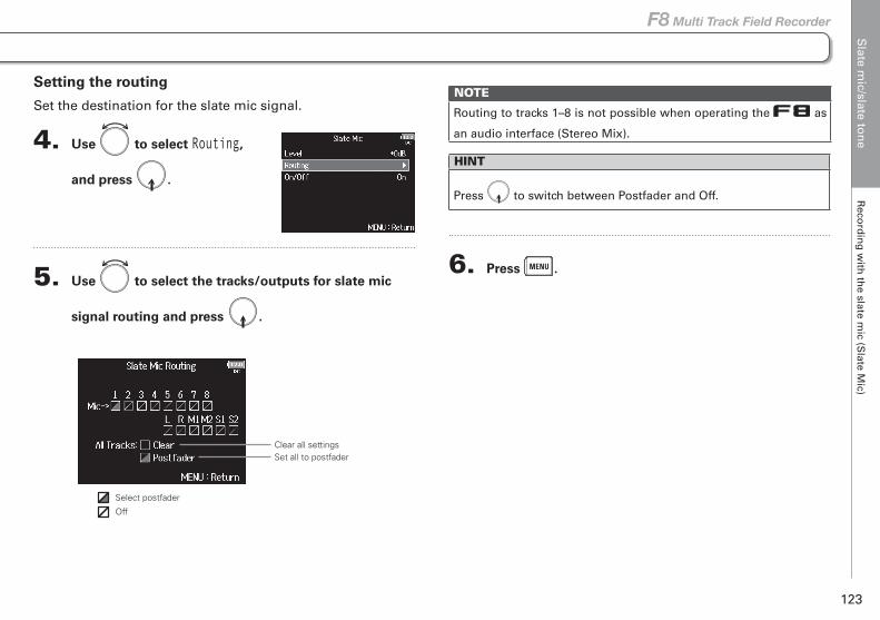
Slate m
ic/slate ton
e R
ecord
ing
with
the slate m
ic (Slate M
ic)
123
F8 Multi Track Field Recorder
NOTE
Routing to tracks 1–8 is not possible when operating the as
an audio interface (Stereo Mix).
HINT
Press to switch between Postfader and Off.
6. Press .
Setting the routing
Set the destination for the slate mic signal.
4. Use to select Routing,
and press .
5. Use to select the tracks/outputs for slate mic
signal routing and press .
Clear all settingsSet all to postfader
Select postfader
Off
Recording with the slate mic (Slate Mic)
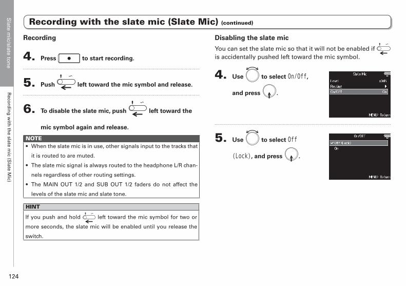
Slate m
ic/slate ton
e R
ecord
ing
with
the slate m
ic (Slate M
ic)
124
Disabling the slate mic
You can set the slate mic so that it will not be enabled if is accidentally pushed left toward the mic symbol.
4. Use to select On/Off,
and press .
5. Use to select Off
(Lock), and press .
Recording
4. Press to start recording.
5. Push left toward the mic symbol and release.
6. To disable the slate mic, push left toward the
mic symbol again and release.
NOTE• When the slate mic is in use, other signals input to the tracks that
it is routed to are muted.
• The slate mic signal is always routed to the headphone L/R chan-
nels regardless of other routing settings.
• The MAIN OUT 1/2 and SUB OUT 1/2 faders do not affect the
levels of the slate mic and slate tone.
HINT
If you push and hold left toward the mic symbol for two or
more seconds, the slate mic will be enabled until you release the
switch.
Recording with the slate mic (Slate Mic) (continued)
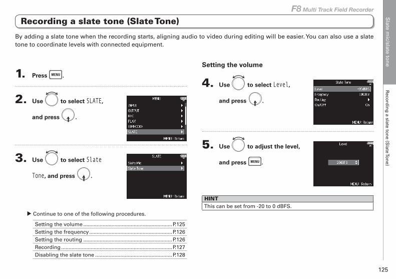
Slate m
ic/slate ton
e R
ecord
ing
a slate ton
e (Slate To
ne)
125
F8 Multi Track Field Recorder
1. Press .
2. Use to select SLATE,
and press .
3. Use to select Slate
Tone, and press .
▶ Continue to one of the following procedures.
Setting the volume ............................................................P.125Setting the frequency ........................................................P.126Setting the routing ............................................................P.126Recording ...........................................................................P.127Disabling the slate tone ....................................................P.128
Setting the volume
4. Use to select Level,
and press .
5. Use to adjust the level,
and press .
HINTThis can be set from -20 to 0 dBFS.
By adding a slate tone when the recording starts, aligning audio to video during editing will be easier. You can also use a slate tone to coordinate levels with connected equipment.
Recording a slate tone (Slate Tone)
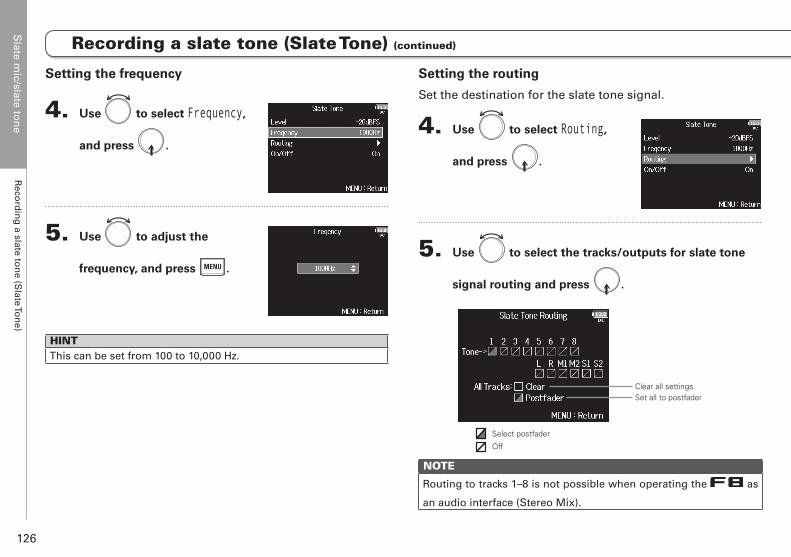
Slate m
ic/slate ton
e R
ecord
ing
a slate ton
e (Slate To
ne)
126
Setting the frequency
4. Use to select Frequency,
and press .
5. Use to adjust the
frequency, and press .
HINTThis can be set from 100 to 10,000 Hz.
Setting the routing
Set the destination for the slate tone signal.
4. Use to select Routing,
and press .
5. Use to select the tracks/outputs for slate tone
signal routing and press .
Clear all settingsSet all to postfader
Select postfader
Off
NOTE
Routing to tracks 1–8 is not possible when operating the as
an audio interface (Stereo Mix).
Recording a slate tone (Slate Tone) (continued)
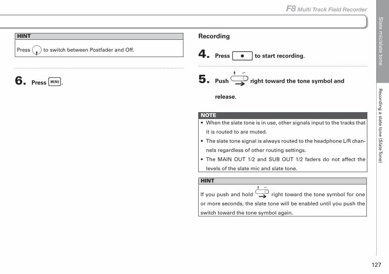
Slate m
ic/slate ton
e R
ecord
ing
a slate ton
e (Slate To
ne)
127
F8 Multi Track Field Recorder
Recording
4. Press to start recording.
5. Push right toward the tone symbol and
release.
NOTE• When the slate tone is in use, other signals input to the tracks that
it is routed to are muted.
• The slate tone signal is always routed to the headphone L/R chan-
nels regardless of other routing settings.
• The MAIN OUT 1/2 and SUB OUT 1/2 faders do not affect the
levels of the slate mic and slate tone.
HINT
If you push and hold right toward the tone symbol for one
or more seconds, the slate tone will be enabled until you push the
switch toward the tone symbol again.
HINT
Press to switch between Postfader and Off.
6. Press .

Slate m
ic/slate ton
e R
ecord
ing
a slate ton
e (Slate To
ne)
128
Disabling the slate tone
You can set the slate tone so that it will not be enabled if is accidentally pushed right toward the tone symbol.
4. Use to select On/Off,
and press .
5. Use to select Off
(Lock), and press .
Recording a slate tone (Slate Tone) (continued)
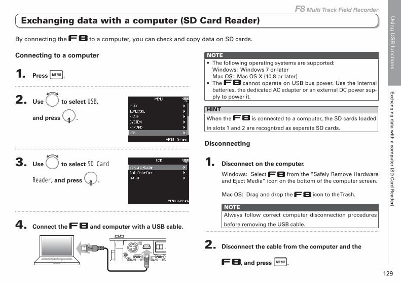
Usin
g U
SB
fun
ction
sE
xchan
gin
g d
ata with
a com
pu
ter (SD
Card
Read
er)
129
F8 Multi Track Field Recorder
Exchanging data with a computer (SD Card Reader)
Using USB functions
Connecting to a computer
1. Press .
2. Use to select USB,
and press .
3. Use to select SD Card
Reader, and press .
4. Connect the and computer with a USB cable.
NOTE• The following operating systems are supported:
Windows: Windows 7 or laterMac OS: Mac OS X (10.8 or later)
• The cannot operate on USB bus power. Use the internal batteries, the dedicated AC adapter or an external DC power sup-ply to power it.
HINT
When the is connected to a computer, the SD cards loaded
in slots 1 and 2 are recognized as separate SD cards.
Disconnecting
1. Disconnect on the computer.
Windows: Select from the “Safely Remove Hardware and Eject Media” icon on the bottom of the computer screen.
Mac OS: Drag and drop the icon to the Trash.
NOTEAlways follow correct computer disconnection procedures
before removing the USB cable.
2. Disconnect the cable from the computer and the
, and press .
By connecting the to a computer, you can check and copy data on SD cards.

Usin
g U
SB
fun
ction
sU
sing
as an au
dio
interface (A
ud
io In
terface)
130
Using as an audio interface (Audio Interface)
Connecting to a computer or an iOS device
1. Press .
2. Use to select USB,
and press .
3. Use to select Audio
Interface, and press .
4. Use to select the mode
and connected device,
and press .
Setting value Explanation
Stereo Mix (PC/Mac)
This is a 2-in/2-out connection mode for Mac/Windows and sends tracks 1–8 as a stereo mix.
Stereo Mix (iPad)
This is a 2-in/2-out connection mode for iOS devices and sends tracks 1–8 as a stereo mix.
Multi Track (PC/Mac)
This is an 8-in/4-out connection mode for Mac/Win-dows and sends tracks 1–8 as separate signals (cannot be used with an iOS device).A driver is necessary for use with Windows. Download the driver from the ZOOM website (www.zoom.co.jp/).
5. Use a USB cable to connect the and the
computer or iOS device.
NOTE• A Lightning to USB Camera Adapter is necessary to connect an
iOS device.• The cannot operate on USB bus power. Use the internal
batteries, the dedicated AC adapter or an external DC power sup-ply to power it.
input signals can be input directly to a computer or an iOS device, and playback signals coming from a computer or an iOS device can be output from the .
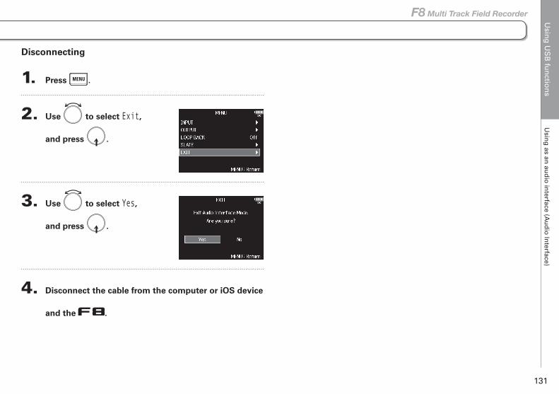
Usin
g U
SB
fun
ction
sU
sing
as an au
dio
interface (A
ud
io In
terface)
131
F8 Multi Track Field Recorder
Using as an audio interface (Audio Interface)
Disconnecting
1. Press .
2. Use to select Exit,
and press .
3. Use to select Yes,
and press .
4. Disconnect the cable from the computer or iOS device
and the .
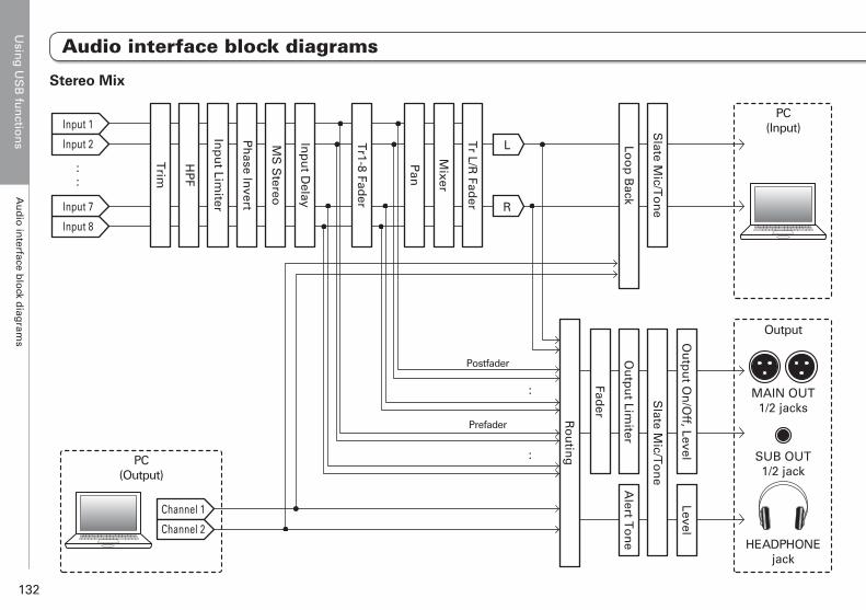
Usin
g U
SB
fun
ction
sA
ud
io in
terface blo
ck diag
rams
132
Audio interface block diagrams
MAIN OUT1/2 jacks
SUB OUT1/2 jack
HEADPHONEjack
PC(Input)
Output
PC(Output)
::
Trim
HP
F
Inp
ut Lim
iter
Ph
ase Invert
MS
Stereo
Inp
ut D
elay
Pan
Tr1-8 Fad
er
Mixer
Tr L/R
Fader
L
R
Ou
tpu
t On
/Off, Level
Level
Slate M
ic/To
ne
Ou
tpu
t Limiter
Fader
Alert T
on
e
Slate M
ic/To
ne
Loo
p B
ack
Ro
utin
g
:
:
Channel 1
Channel 2
Input 1
Input 2
Input 7
Input 8
Postfader
Prefader
Stereo Mix
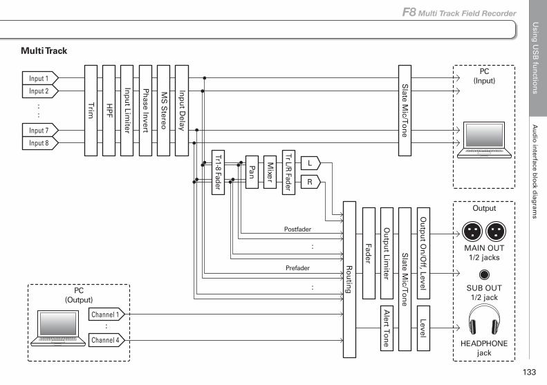
Usin
g U
SB
fun
ction
sA
ud
io in
terface blo
ck diag
rams
133
F8 Multi Track Field Recorder
Audio interface block diagrams
PC(Input)
PC(Output)
::
Trim
HP
F
Inp
ut Lim
iter
Ph
ase Invert
MS
Stereo
Inp
ut D
elay
Ou
tpu
t On
/Off, Level
Level
Slate M
ic/To
ne
Ou
tpu
t Limiter
Fader
Alert T
on
e
Slate M
ic/To
ne
Ro
utin
g
:
:
:
Channel 1
Channel 4
Tr1-8 Fader
Mixe
r
L
R
Tr L/R Fader
Pan
Input 1
Input 2
Input 7
Input 8
MAIN OUT1/2 jacks
SUB OUT1/2 jack
HEADPHONEjack
Output
Postfader
Prefader
Multi Track
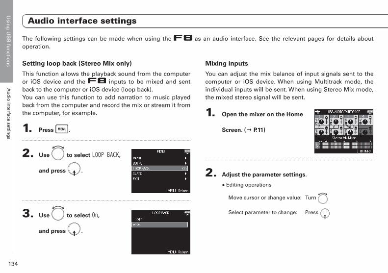
Usin
g U
SB
fun
ction
sA
ud
io in
terface setting
s
134
Audio interface settings
Setting loop back (Stereo Mix only)
This function allows the playback sound from the computer or iOS device and the inputs to be mixed and sent back to the computer or iOS device (loop back).You can use this function to add narration to music played back from the computer and record the mix or stream it from the computer, for example.
1. Press .
2. Use to select LOOP BACK,
and press .
3. Use to select On,
and press .
Mixing inputs
You can adjust the mix balance of input signals sent to the computer or iOS device. When using Multitrack mode, the individual inputs will be sent. When using Stereo Mix mode, the mixed stereo signal will be sent.
1. Open the mixer on the Home
Screen. (→ P.11)
2. Adjust the parameter settings.
■ Editing operations
Move cursor or change value: Turn
Select parameter to change: Press
The following settings can be made when using the as an audio interface. See the relevant pages for details about operation.
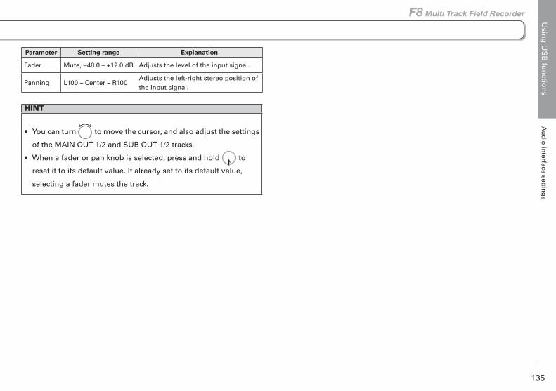
Usin
g U
SB
fun
ction
sA
ud
io in
terface setting
s
135
F8 Multi Track Field Recorder
Audio interface settings
Parameter Setting range Explanation
Fader Mute, −48.0 – +12.0 dB Adjusts the level of the input signal.
Panning L100 – Center – R100Adjusts the left-right stereo position of the input signal.
HINT
• You can turn to move the cursor, and also adjust the settings
of the MAIN OUT 1/2 and SUB OUT 1/2 tracks.
• When a fader or pan knob is selected, press and hold to
reset it to its default value. If already set to its default value,
selecting a fader mutes the track.
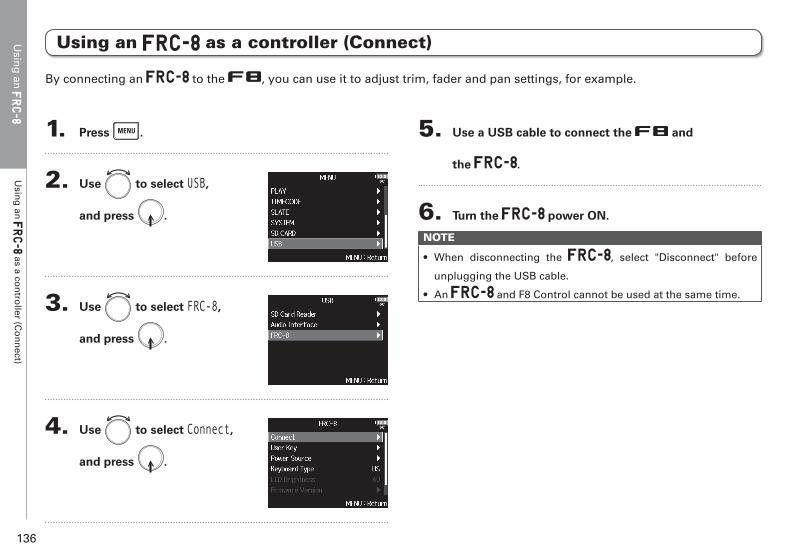
Using an
Usin
g an
U
sing
an
as a con
troller (C
on
nect)
136
1. Press .
2. Use to select USB,
and press .
3. Use to select FRC-8,
and press .
4. Use to select Connect,
and press .
5. Use a USB cable to connect the and
the .
6. Turn the power ON.
NOTE
• When disconnecting the , select "Disconnect" before
unplugging the USB cable.
• An and F8 Control cannot be used at the same time.
Using an as a controller (Connect)
By connecting an to the , you can use it to adjust trim, fader and pan settings, for example.
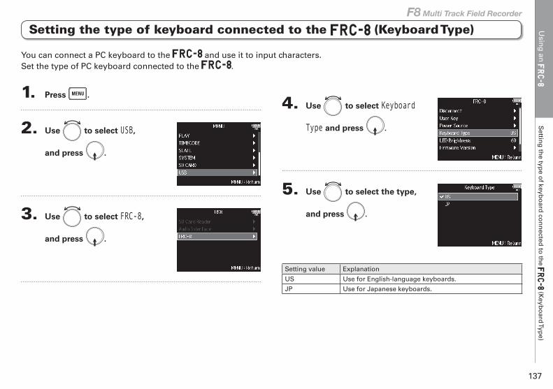
Usin
g an
S
etting
the typ
e of keyb
oard
con
nected
to th
e (K
eybo
ard Typ
e)
137
F8 Multi Track Field Recorder
You can connect a PC keyboard to the and use it to input characters.Set the type of PC keyboard connected to the .
Setting the type of keyboard connected to the (Keyboard Type)
1. Press .
2. Use to select USB,
and press .
3. Use to select FRC-8,
and press .
4. Use to select Keyboard
Type and press .
5. Use to select the type,
and press .
Setting value Explanation
US Use for English-language keyboards.
JP Use for Japanese keyboards.
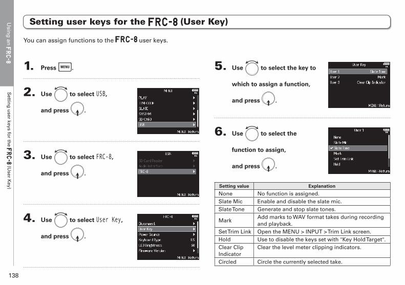
Usin
g an
S
etting
user keys fo
r the
(User K
ey)
138
You can assign functions to the user keys.
5. Use to select the key to
which to assign a function,
and press .
6. Use to select the
function to assign,
and press .
Setting value Explanation
None No function is assigned.Slate Mic Enable and disable the slate mic.Slate Tone Generate and stop slate tones.
MarkAdd marks to WAV format takes during recording and playback.
Set Trim Link Open the MENU > INPUT > Trim Link screen.Hold Use to disable the keys set with "Key Hold Target".Clear Clip Indicator
Clear the level meter clipping indicators.
Circled Circle the currently selected take.
Setting user keys for the (User Key)
1. Press .
2. Use to select USB,
and press .
3. Use to select FRC-8,
and press .
4. Use to select User Key,
and press .
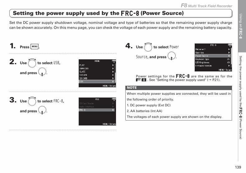
Usin
g an
S
etting
the p
ow
er sup
ply u
sed b
y the
(Pow
er So
urce)
139
F8 Multi Track Field Recorder
Set the DC power supply shutdown voltage, nominal voltage and type of batteries so that the remaining power supply charge can be shown accurately. On this menu page, you can check the voltage of each power supply and the remaining battery capacity.
4. Use to select Power
Source, and press .
Power settings for the are the same as for the . See "Setting the power supply used" (→ P.21).
NOTE
When multiple power supplies are connected, they will be used in
the following order of priority.
1. DC power supply (Ext DC)
2. AA batteries (Int AA)
The voltages of each power supply are shown on the display.
Setting the power supply used by the (Power Source)
1. Press .
2. Use to select USB,
and press .
3. Use to select FRC-8,
and press .
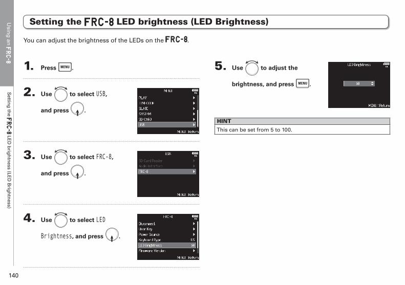
Usin
g an
S
etting
the
LED
brig
htn
ess (LED
Brig
htn
ess)
140
Setting the LED brightness (LED Brightness)
1. Press .
2. Use to select USB,
and press .
3. Use to select FRC-8,
and press .
4. Use to select LED
Brightness, and press .
5. Use to adjust the
brightness, and press .
HINT
This can be set from 5 to 100.
You can adjust the brightness of the LEDs on the .
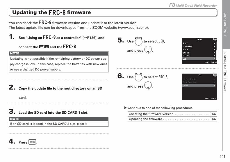
Usin
g an
U
pd
ating
the
firm
ware
141
F8 Multi Track Field Recorder
Updating the firmware
1. See "Using an as a controller" (→P.136), and
connect the and the .
NOTE
Updating is not possible if the remaining battery or DC power sup-
ply charge is low. In this case, replace the batteries with new ones
or use a charged DC power supply.
2. Copy the update file to the root directory on an SD
card.
3. Load the SD card into the SD CARD 1 slot.
NOTE
If an SD card is loaded in the SD CARD 2 slot, eject it.
4. Press .
5. Use to select USB,
and press .
6. Use to select FRC-8,
and press .
▶ Continue to one of the following procedures.
Checking the firmware version . . . . . . . . . . . . . . . . . . . . P.142
Updating the firmware . . . . . . . . . . . . . . . . . . . . . . . . . . . P.142
You can check the firmware version and update it to the latest version.The latest update file can be downloaded from the ZOOM website (www.zoom.co.jp).
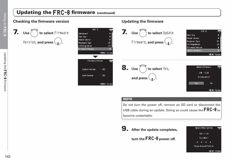
Usin
g an
U
pd
ating
the
firm
ware
142
Updating the firmware (continued)
Updating the firmware
7. Use to select Update
Firmware, and press .
8. Use to select Yes,
and press .
NOTE
Do not turn the power off, remove an SD card or disconnect the
USB cable during an update. Doing so could cause the to
become unstartable.
9. After the update completes,
turn the power off.
Checking the firmware version
7. Use to select Firmware
Version, and press .
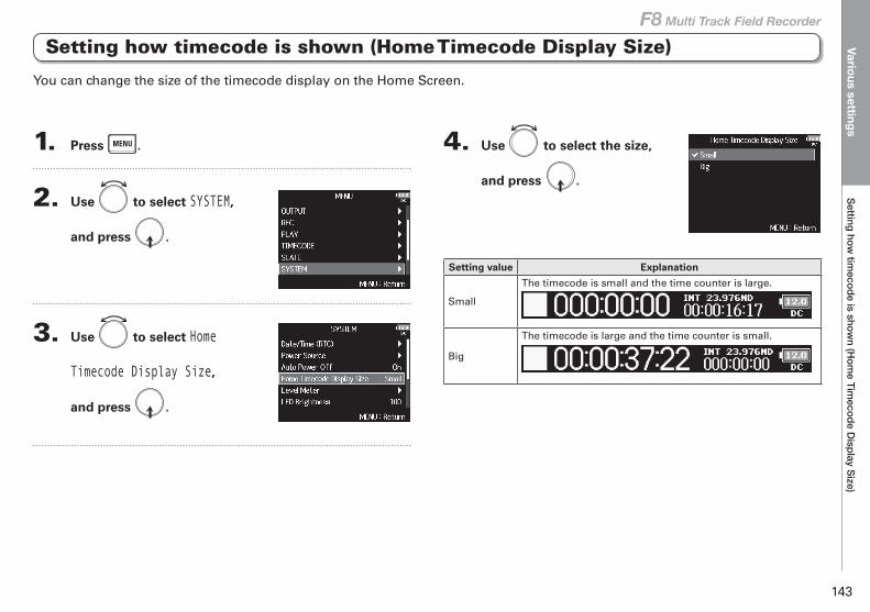
Various settingsSetting how
timecode is show
n (Hom
e Timecode D
isplay Size)
143
F8 Multi Track Field Recorder
Setting how timecode is shown (Home Timecode Display Size)
Various settings
1. Press .
2. Use to select SYSTEM,
and press .
3. Use to select Home
Timecode Display Size,
and press .
4. Use to select the size,
and press .
Setting value Explanation
Small
The timecode is small and the time counter is large.
Big
The timecode is large and the time counter is small.
You can change the size of the timecode display on the Home Screen.
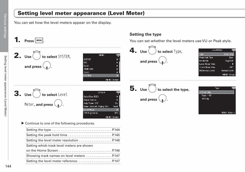
Variou
s setting
sS
etting
level meter ap
pearan
ce (Level Meter)
144
1. Press .
2. Use to select SYSTEM,
and press .
3. Use to select Level
Meter, and press .
▶ Continue to one of the following procedures.
Setting the type . . . . . . . . . . . . . . . . . . . . . . . . . . . . . . . . . P.144
Setting the peak hold time . . . . . . . . . . . . . . . . . . . . . . . . P.145
Setting the level meter resolution . . . . . . . . . . . . . . . . . . P.146
Setting which track level meters are shown
on the Home Screen . . . . . . . . . . . . . . . . . . . . . . . . . . . . . P.146
Showing track names on level meters . . . . . . . . . . . . . . P.147
Setting the level meter reference. . . . . . . . . . . . . . . . . . . P.147
Setting the type
You can set whether the level meters use VU or Peak style.
4. Use to select Type,
and press .
5. Use to select the type,
and press .
You can set how the level meters appear on the display.
Setting level meter appearance (Level Meter)
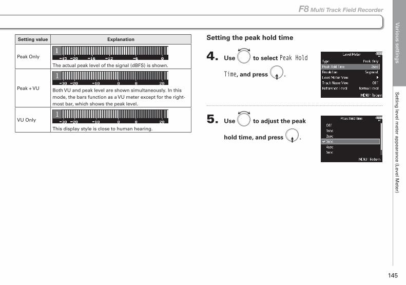
Variou
s setting
sS
etting
level meter ap
pearan
ce (Level Meter)
145
F8 Multi Track Field Recorder
Setting level meter appearance (Level Meter)
Setting value Explanation
Peak Only
The actual peak level of the signal (dBFS) is shown.
Peak + VU Both VU and peak level are shown simultaneously. In this mode, the bars function as a VU meter except for the right-most bar, which shows the peak level.
VU Only
This display style is close to human hearing.
Setting the peak hold time
4. Use to select Peak Hold
Time, and press .
5. Use to adjust the peak
hold time, and press .
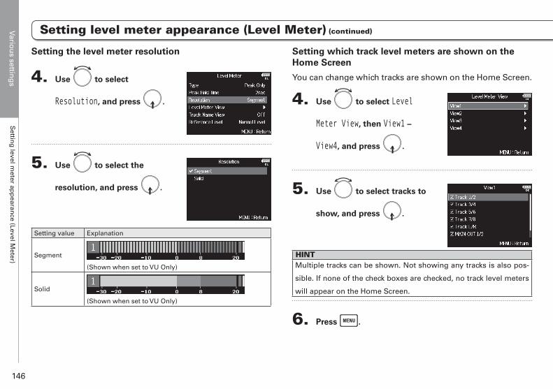
Variou
s setting
sS
etting
level meter ap
pearan
ce (Level Meter)
146
Setting which track level meters are shown on the Home Screen
You can change which tracks are shown on the Home Screen.
4. Use to select Level
Meter View, then View1 –
View4, and press .
5. Use to select tracks to
show, and press .
HINTMultiple tracks can be shown. Not showing any tracks is also pos-
sible. If none of the check boxes are checked, no track level meters
will appear on the Home Screen.
6. Press .
Setting the level meter resolution
4. Use to select
Resolution, and press .
5. Use to select the
resolution, and press .
Setting value Explanation
Segment
(Shown when set to VU Only)
Solid
(Shown when set to VU Only)
Setting level meter appearance (Level Meter) (continued)Setting level meter appearance (Level Meter) (continued)
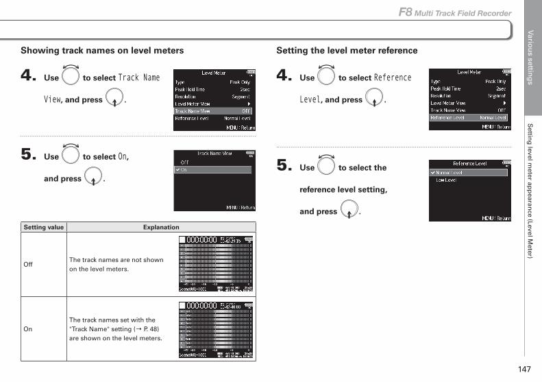
Setting level meter appearance (Level Meter) (continued)Setting level meter appearance (Level Meter) (continued) Variou
s setting
sS
etting
level meter ap
pearan
ce (Level Meter)
147
F8 Multi Track Field Recorder
Setting the level meter reference
4. Use to select Reference
Level, and press .
5. Use to select the
reference level setting,
and press .
Showing track names on level meters
4. Use to select Track Name
View, and press .
5. Use to select On,
and press .
Setting value Explanation
OffThe track names are not shown on the level meters.
OnThe track names set with the "Track Name" setting (→ P. 48) are shown on the level meters.
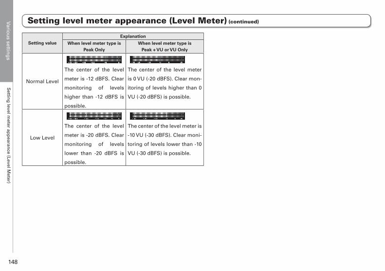
Variou
s setting
sS
etting
level meter ap
pearan
ce (Level Meter)
148
Setting level meter appearance (Level Meter) (continued)
Setting valueExplanation
When level meter type isPeak Only
When level meter type isPeak + VU or VU Only
Normal Level
The center of the level
meter is -12 dBFS. Clear
monitoring of levels
higher than -12 dBFS is
possible.
The center of the level meter
is 0 VU (-20 dBFS). Clear mon-
itoring of levels higher than 0
VU (-20 dBFS) is possible.
Low Level
The center of the level
meter is -20 dBFS. Clear
monitoring of levels
lower than -20 dBFS is
possible.
The center of the level meter is
-10 VU (-30 dBFS). Clear moni-
toring of levels lower than -10
VU (-30 dBFS) is possible.
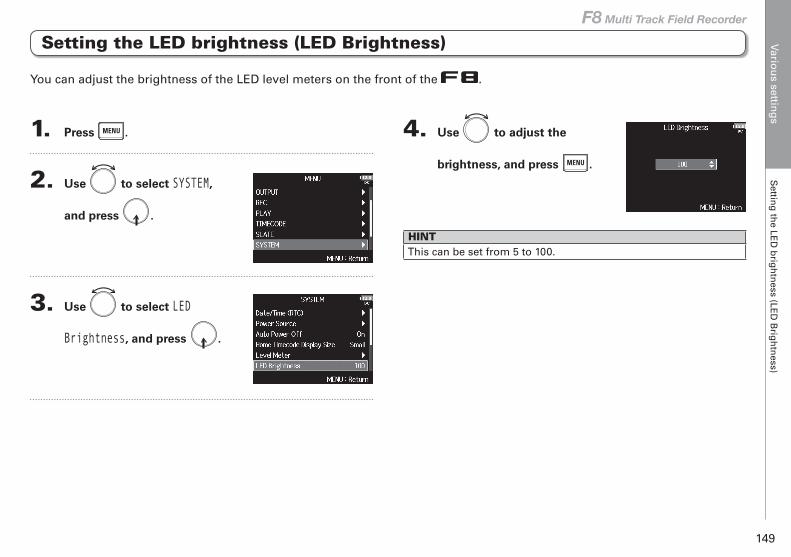
Variou
s setting
sS
etting
the LE
D b
righ
tness (LE
D B
righ
tness)
149
F8 Multi Track Field Recorder
Setting the LED brightness (LED Brightness)
1. Press .
2. Use to select SYSTEM,
and press .
3. Use to select LED
Brightness, and press .
4. Use to adjust the
brightness, and press .
HINTThis can be set from 5 to 100.
You can adjust the brightness of the LED level meters on the front of the .
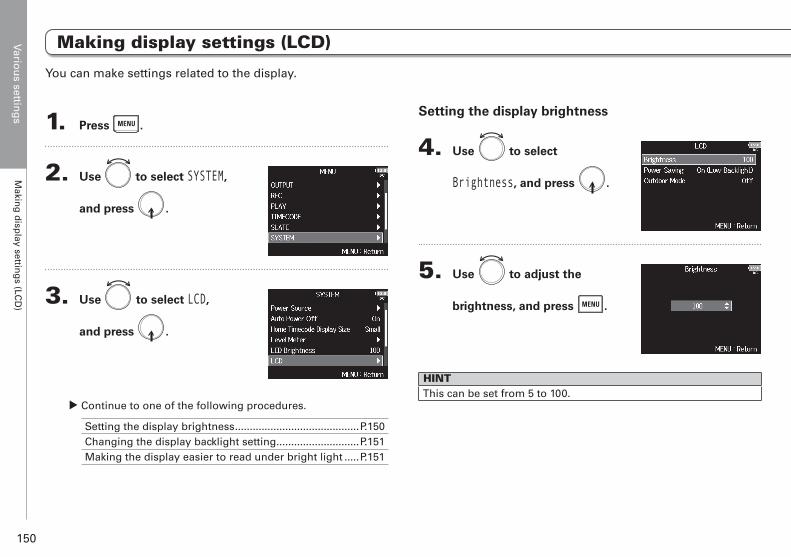
Variou
s setting
sM
aking
disp
lay setting
s (LCD
)
150
1. Press .
2. Use to select SYSTEM,
and press .
3. Use to select LCD,
and press .
▶ Continue to one of the following procedures.
Setting the display brightness ..........................................P.150Changing the display backlight setting ............................P.151Making the display easier to read under bright light .....P.151
Setting the display brightness
4. Use to select
Brightness, and press .
5. Use to adjust the
brightness, and press .
HINTThis can be set from 5 to 100.
You can make settings related to the display.
Making display settings (LCD)
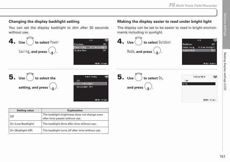
Variou
s setting
sM
aking
disp
lay setting
s (LCD
)
151
F8 Multi Track Field Recorder
Making display settings (LCD)
Making the display easier to read under bright light
The display can be set to be easier to read in bright environ-ments including in sunlight.
4. Use to select Outdoor
Mode, and press .
5. Use to select On,
and press .
Changing the display backlight setting
You can set the display backlight to dim after 30 seconds without use.
4. Use to select Power
Saving, and press .
5. Use to select the
setting, and press .
Setting value Explanation
OffThe backlight brightness does not change even after time passes without use.
On (Low-Backlight) The backlight dims after time without use.
On (Backlight-Off) The backlight turns off after time without use.
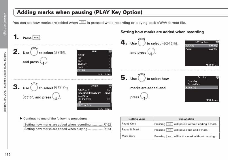
Variou
s setting
sA
dd
ing
marks w
hen
pau
sing
(PLA
Y K
ey Op
tion
)
152
1. Press .
2. Use to select SYSTEM,
and press .
3. Use to select PLAY Key
Option, and press .
▶ Continue to one of the following procedures.
Setting how marks are added when recording ...............P.152Setting how marks are added when playing ..................P.153
Setting how marks are added when recording
4. Use to select Recording,
and press .
5. Use to select how
marks are added, and
press .
Setting value Explanation
Pause Only Pressing will pause without adding a mark.
Pause & Mark Pressing will pause and add a mark.
Mark Only Pressing will add a mark without pausing.
You can set how marks are added when is pressed while recording or playing back a WAV format file.
Adding marks when pausing (PLAY Key Option)

Variou
s setting
sA
dd
ing
marks w
hen
pau
sing
(PLA
Y K
ey Op
tion
)
153
F8 Multi Track Field Recorder
Adding marks when pausing (PLAY Key Option)
Setting how marks are added when playing
4. Use to select Playing,
and press .
5. Use to select how
marks are added, and
press .
Setting value Explanation
Pause Only Pressing will pause without adding a mark.
Pause & Mark Pressing will pause and add a mark.
Mark Only Pressing will add a mark without pausing.
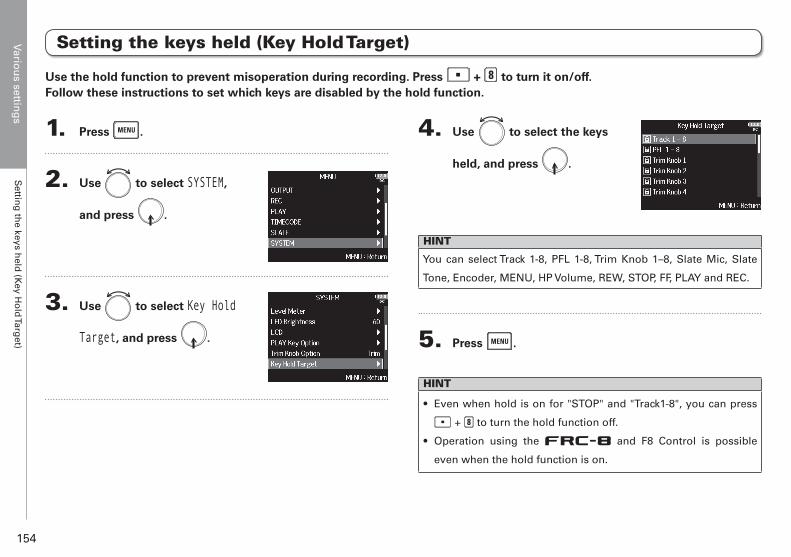
Variou
s setting
sS
etting
the keys h
eld (K
ey Ho
ld Targ
et)
154
1. Press .
2. Use to select SYSTEM,
and press .
3. Use to select Key Hold
Target, and press .
4. Use to select the keys
held, and press .
HINT
You can select Track 1-8, PFL 1-8, Trim Knob 1–8, Slate Mic, Slate
Tone, Encoder, MENU, HP Volume, REW, STOP, FF, PLAY and REC.
5. Press .
HINT
• Even when hold is on for "STOP" and "Track1-8", you can press
+ to turn the hold function off.
• Operation using the R and F8 Control is possible
even when the hold function is on.
Setting the keys held (Key Hold Target)
Use the hold function to prevent misoperation during recording. Press + to turn it on/off.Follow these instructions to set which keys are disabled by the hold function.
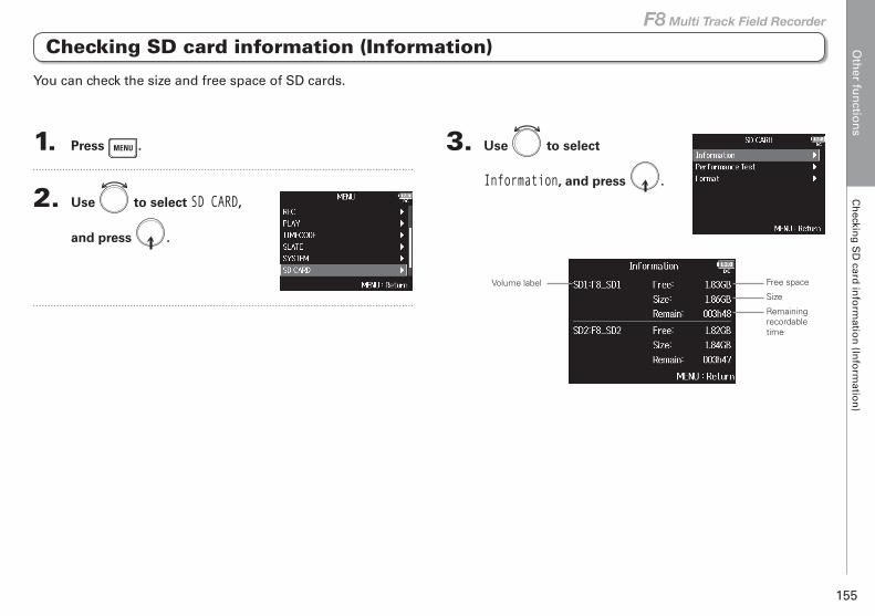
Oth
er fun
ction
sC
heckin
g S
D card
info
rmatio
n (In
form
ation
)
155
F8 Multi Track Field Recorder
Checking SD card information (Information)
Other functions
1. Press .
2. Use to select SD CARD,
and press .
3. Use to select
Information, and press .
Free spaceVolume label
Size
Remaining recordable time
You can check the size and free space of SD cards.
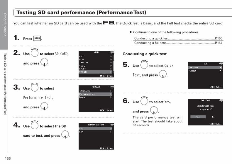
Oth
er fun
ction
sTestin
g S
D card
perfo
rman
ce (Perform
ance Test)
156
You can test whether an SD card can be used with the . The Quick Test is basic, and the Full Test checks the entire SD card.
Testing SD card performance (Performance Test)
1. Press .
2. Use to select SD CARD,
and press .
3. Use to select
Performance Test,
and press .
4. Use to select the SD
card to test, and press .
▶ Continue to one of the following procedures.
Conducting a quick test .....................................................P.156Conducting a full test ........................................................P.157
Conducting a quick test
5. Use to select Quick
Test, and press .
6. Use to select Yes,
and press .
The card performance test will start. The test should take about 30 seconds.

Oth
er fun
ction
sTestin
g S
D card
perfo
rman
ce (Perform
ance Test)
157
F8 Multi Track Field Recorder
Conducting a full test
5. Use to select Full Test,
and press .
The amount of time required for the full test will be shown.
6. Use to select Yes,
and press .
7. The test completes.
The result of the evaluation will be shown. If the access rate MAX reaches 100%, the card will fail (NG).
7. The test completes.
The result of the evaluation will be shown.
8. Press to stop the test.
NOTEEven if a performance test result is "OK", there is no guarantee
that writing errors will not occur. This information is just to provide
guidance.
Oth
er fun
ction
sTestin
g S
D card
perfo
rman
ce (Perform
ance Test)
158
8. Press to stop the test.
NOTE
• You can press to pause and resume the test.
• Even if a performance test result is "OK", there is no guar-
antee that writing errors will not occur. This information is
just to provide guidance.
Testing SD card performance (Performance Test) (continued)
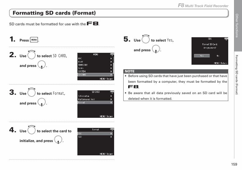
Oth
er fun
ction
sFo
rmattin
g S
D card
s (Form
at)
159
F8 Multi Track Field Recorder
1. Press .
2. Use to select SD CARD,
and press .
3. Use to select Format,
and press .
4. Use to select the card to
initialize, and press .
5. Use to select Yes,
and press .
NOTE• Before using SD cards that have just been purchased or that have
been formatted by a computer, they must be formatted by the
.
• Be aware that all data previously saved on an SD card will be
deleted when it is formatted.
Formatting SD cards (Format)
SD cards must be formatted for use with the .
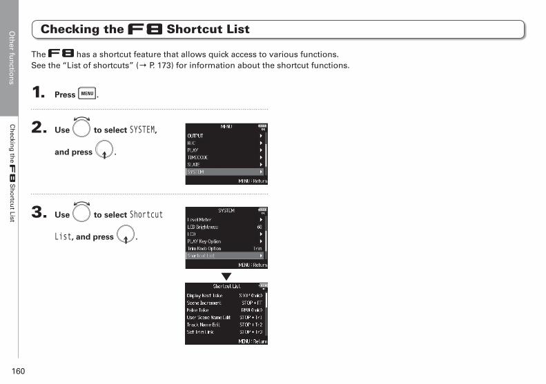
Oth
er fun
ction
sC
heckin
g th
e S
ho
rtcut List
160
Checking the Shortcut List
1. Press .
2. Use to select SYSTEM,
and press .
3. Use to select Shortcut
List, and press .
The has a shortcut feature that allows quick access to various functions.See the “List of shortcuts” (→ P. 173) for information about the shortcut functions.
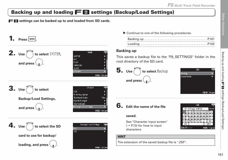
Oth
er fun
ction
sB
acking
up
and
load
ing
settin
gs (B
ackup
/Load
Settin
gs)
161
F8 Multi Track Field Recorder
settings can be backed up to and loaded from SD cards.
1. Press .
2. Use to select SYSTEM,
and press .
3. Use to select
Backup/Load Settings,
and press .
4. Use to select the SD
card to use for backup/
loading, and press .
▶ Continue to one of the following procedures.
Backing up . . . . . . . . . . . . . . . . . . . . . . . . . . . . . . . . . . . . . P.161
Loading. . . . . . . . . . . . . . . . . . . . . . . . . . . . . . . . . . . . . . . . P.162
Backing up
This saves a backup file to the "F8_SETTINGS" folder in the root directory of the SD card.
5. Use to select Backup
and press .
6. Edit the name of the file
saved.
See "Character input screen" (→ P.13) for how to input characters.
HINT
The extension of the saved backup file is ".ZSF".
Backing up and loading settings (Backup/Load Settings)
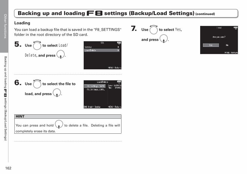
Oth
er fun
ction
sB
acking
up
and
load
ing
settin
gs (B
ackup
/Load
Settin
gs)
162
Backing up and loading settings (Backup/Load Settings) (continued)
7. Use to select Yes,
and press .
Loading
You can load a backup file that is saved in the "F8_SETTINGS" folder in the root directory of the SD card.
5. Use to select Load/
Delete, and press .
6. Use to select the file to
load, and press .
HINT
You can press and hold to delete a file. Deleting a file will
completely erase its data.
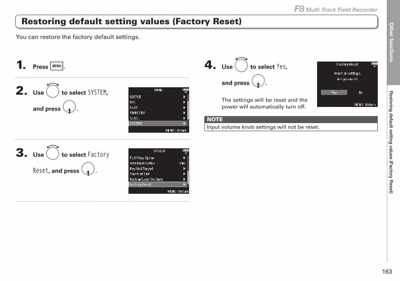
Other functions
Restoring default setting values (Factory Reset)
163
F8 Multi Track Field Recorder
1. Press .
2. Use to select SYSTEM,
and press .
3. Use to select Factory
Reset, and press .
4. Use to select Yes,
and press .
The settings will be reset and the power will automatically turn off.
NOTEInput volume knob settings will not be reset.
You can restore the factory default settings.
Restoring default setting values (Factory Reset)
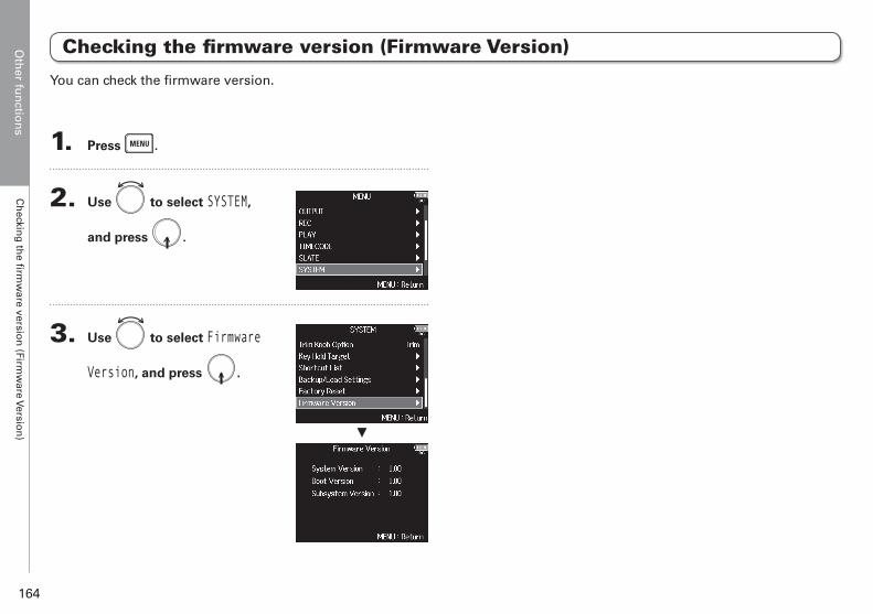
Oth
er fun
ction
sC
heckin
g th
e firm
ware versio
n (Firm
ware Versio
n)
164
Checking the firmware version (Firmware Version)
1. Press .
2. Use to select SYSTEM,
and press .
3. Use to select Firmware
Version, and press .
▼
You can check the firmware version.
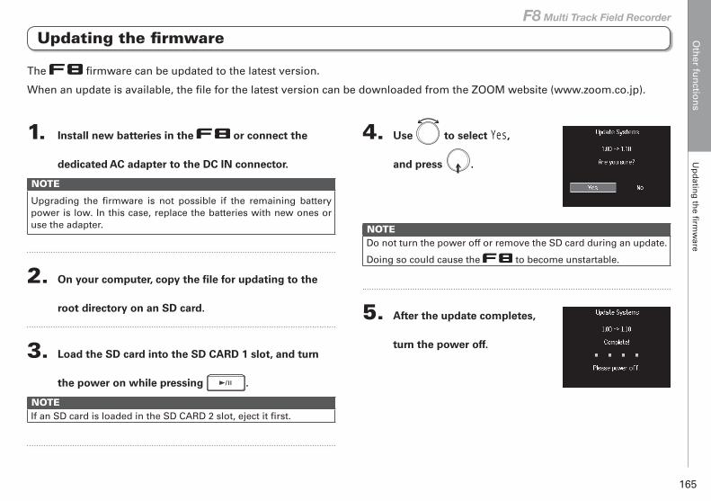
Oth
er fun
ction
sU
pd
ating
the fi
rmw
are
165
F8 Multi Track Field Recorder
Updating the firmware
1. Install new batteries in the or connect the
dedicated AC adapter to the DC IN connector.
NOTE
Upgrading the firmware is not possible if the remaining battery power is low. In this case, replace the batteries with new ones or use the adapter.
2. On your computer, copy the file for updating to the
root directory on an SD card.
3. Load the SD card into the SD CARD 1 slot, and turn
the power on while pressing .
NOTEIf an SD card is loaded in the SD CARD 2 slot, eject it first.
4. Use to select Yes,
and press .
NOTEDo not turn the power off or remove the SD card during an update.
Doing so could cause the to become unstartable.
5. After the update completes,
turn the power off.
The firmware can be updated to the latest version.
When an update is available, the file for the latest version can be downloaded from the ZOOM website (www.zoom.co.jp).
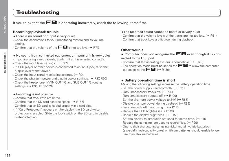
Ap
pen
dices
Trou
blesh
oo
ting
166
Troubleshooting
Appendices
Recording/playback trouble◆ There is no sound or output is very quiet· Check the connections to your monitoring system and its volume setting.
· Confirm that the volume of the is not too low. (→ P.74)
◆ No sound from connected equipment or inputs or it is very quiet· If you are using a mic capsule, confirm that it is oriented correctly.· Check the input level settings. (→ P.27)· If a CD player or other device is connected to an input jack, raise the output level of that device.
· Check the input signal monitoring settings. (→ P.74)· Check the phantom power and plug-in power settings. (→ P.87, P.90)· Check the headphone, MAIN OUT 1/2 and SUB OUT 1/2 routing settings. (→ P.96, P.108-109)
◆ Recording is not possible· Confirm that track keys are lit red.· Confirm that the SD card has free space. (→ P.155)· Confirm that an SD card is loaded properly in a card slot.· If “Card Protected!” appears on the display, the SD card write-protection is enabled. Slide the lock switch on the SD card to disable write-protection.
◆ The recorded sound cannot be heard or is very quiet· Confirm that the volume levels of the tracks are not too low. (→ P.51)· Confirm that track keys are lit green during playback.
Other trouble◆ Computer does not recognize the even though it is con-nected to the USB port· Confirm that the operating system is compatible. (→ P.129) · The operation mode must be set on the to allow the computer
to recognize the . (→ P.130)
◆ Battery operation time is shortMaking the following settings increase the battery operation time. · Set the power supply used correctly. (→ P.21)· Turn unnecessary tracks off. (→ P.26)· Turn unnecessary outputs off. (→ P.100)· Set the phantom power voltage to 24V. (→ P.88)· Disable phantom power during playback. (→ P.89)· Turn timecode off if not using it. (→ P.113)· Reduce the LED brightness.(→ P.149)· Reduce the display brightness. (→ P.150)· Set the display to dim when not used for some time. (→ P.151)· Reduce the sampling rate used to record files. (→ P.29)· Due to their characteristics, using nickel metal hydride batteries (especially high-capacity ones) or lithium batteries should enable longer use than alkaline batteries.
If you think that the is operating incorrectly, check the following items first.
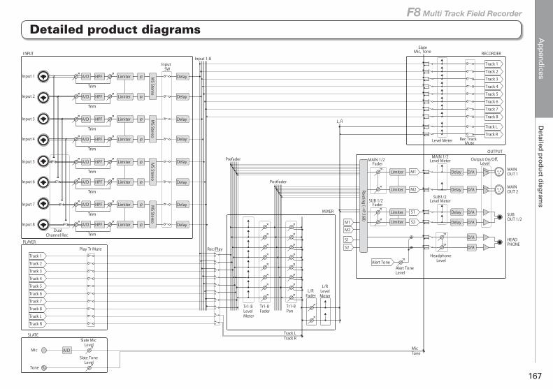
Ap
pen
dices
Detailed
pro
du
ct diag
rams
167
F8 Multi Track Field Recorder
Detailed product diagrams
Input 1
Input SW
Play Tr MutePLAYER
Mic
Tone
SLATE
I NPUT
Rec/Play
Input 1-8
Tr1-8Fader
Tr1-8Pan
HeadphoneLevel
Alert ToneLevel
HEADPHONE
MAINOUT 1
MAINOUT 2
SUBOUT 1/2
OUTPUT
RECORDER
MIXER
L, R
Input 2
Input 3
Input 4
Input 5
Input 6
Input 7
Input 8
Tr1-8LevelMeter
L/RLevelMeter
L/RFader
Prefader
Postfader
MicTone
Track LTrack R
SUB1/2Level Meter
Output On/Off, Level
Slate ToneLevel
Slate MicLevel
Level Meter
SlateMic, Tone
MAIN 1/2Level MeterMAIN 1/2
Fader
SUB 1/2Fader
Rec TrackMute
Routing (→P.168)
Dual Channel Rec
Track 1Track 2Track 3Track 4Track 5Track 6Track 7Track 8
Track LTrack R
M1
M2
S1
S2M1M2
S1S2
Alert ToneTrack 1Track 2Track 3Track 4Track 5Track 6Track 7Track 8Track LTrack R
Trim
A/D LimiterHPF φ
Trim
A/D LimiterHPF φ
Trim
A/D LimiterHPF φ
Trim
A/D LimiterHPF φ
Trim
A/D LimiterHPF φ
Trim
A/D LimiterHPF φ
Trim
A/D LimiterHPF φ
Trim
A/D LimiterHPF φ
D/A
D/A
D/A
D/A
D/A
D/A
MS Stereo
MS Stereo
MS Stereo
MS Stereo
Delay
Delay
Delay
Delay
Delay
Delay
Delay
Delay
A/D
Delay
Delay
Delay
Delay
Limiter
Limiter
Limiter
Limiter
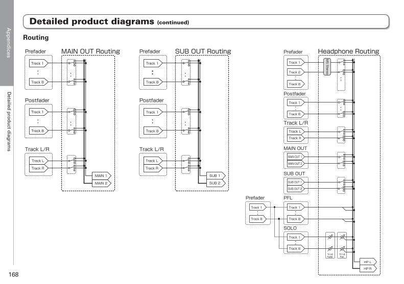
Ap
pen
dices
Detailed
pro
du
ct diag
rams
168
Prefader
Postfader
Track L/R
:
:
:
MAIN OUT Routing
:
Prefader
Postfader
:
:
:
SUB OUT Routing
:
Prefader
Track L/R
: :
Headphone Routing
Postfader
: :
MAIN OUT
SUB OUT
Track 1
Track 8
Track 1
Track 8
Track R
Track L
:
:
Track 1
Track 8
Track 1
Track 8
Track R
Track L
MAIN 2
MAIN 1
Track 1
Track 2
Track 8
Track 1
Track 8
PFL
:Track 1
Track 8
SOLO
:Track 1
Track 8
Prefader
:Track 1
Track 8
Track L
Track R
SUB 1
SUB 2 SUB OUT 1
SUB OUT 2
MAIN OUT 1
MAIN OUT 2
HP L
HP R
MS
Stereo
Tr1-8Fader
Tr1-8Pan
Track L/R
Routing
Detailed product diagrams (continued)
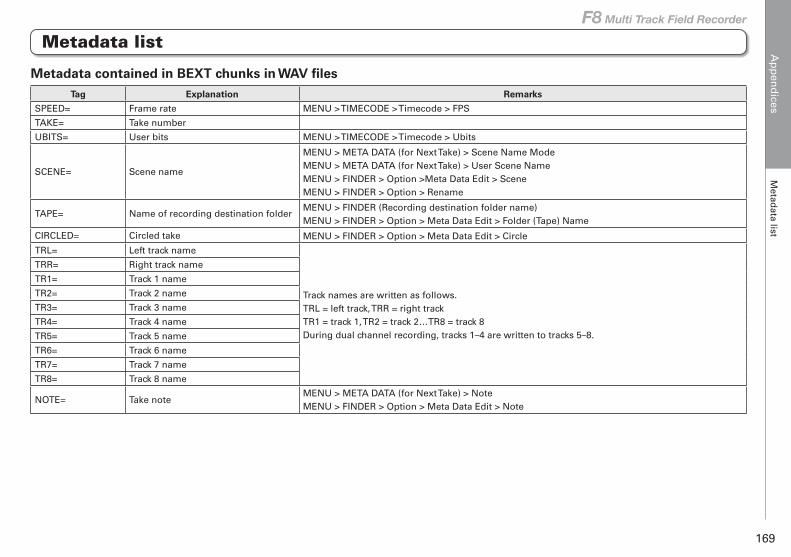
Ap
pen
dices
Metad
ata list
169
F8 Multi Track Field Recorder
Metadata contained in BEXT chunks in WAV filesTag Explanation Remarks
SPEED= Frame rate MENU > TIMECODE > Timecode > FPS
TAKE= Take number
UBITS= User bits MENU > TIMECODE > Timecode > Ubits
SCENE= Scene name
MENU > META DATA (for Next Take) > Scene Name ModeMENU > META DATA (for Next Take) > User Scene NameMENU > FINDER > Option >Meta Data Edit > SceneMENU > FINDER > Option > Rename
TAPE= Name of recording destination folderMENU > FINDER (Recording destination folder name) MENU > FINDER > Option > Meta Data Edit > Folder (Tape) Name
CIRCLED= Circled take MENU > FINDER > Option > Meta Data Edit > Circle
TRL= Left track name
Track names are written as follows. TRL = left track, TRR = right track TR1 = track 1, TR2 = track 2…TR8 = track 8During dual channel recording, tracks 1–4 are written to tracks 5–8.
TRR= Right track name
TR1= Track 1 name
TR2= Track 2 name
TR3= Track 3 name
TR4= Track 4 name
TR5= Track 5 name
TR6= Track 6 name
TR7= Track 7 name
TR8= Track 8 name
NOTE= Take noteMENU > META DATA (for Next Take) > Note MENU > FINDER > Option > Meta Data Edit > Note
Metadata list
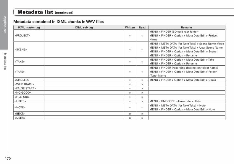
Ap
pen
dices
Metad
ata list
170
Metadata contained in iXML chunks in WAV filesiXML master tag iXML sub tag Written Read Remarks
<PROJECT> ○ ○MENU > FINDER (SD card root folder) MENU > FINDER > Option > Meta Data Edit > Project Name
<SCENE> ○ ○
MENU > META DATA (for Next Take) > Scene Name ModeMENU > META DATA (for Next Take) > User Scene NameMENU > FINDER > Option > Meta Data Edit > SceneMENU > FINDER > Option > Rename
<TAKE> ○ ○MENU > FINDER > Option > Meta Data Edit > TakeMENU > FINDER > Option > Rename
<TAPE> ○ ○MENU > FINDER (recording destination folder name) MENU > FINDER > Option > Meta Data Edit > Folder (Tape) Name
<CIRCLED> ○ ○ MENU > FINDER > Option > Meta Data Edit > Circle
<WILD TRACK> × ×
<FALSE START> × ×
<NO GOOD> × ×
<FILE_UID> ○ ×
<UBITS> ○ × MENU > TIMECODE > Timecode > Ubits
<NOTE> ○ ○MENU > META DATA (for Next Take) > Note MENU > FINDER > Option > Meta Data Edit > Note
<BEXT> × ×
<USER> × ×
Metadata list (continued)
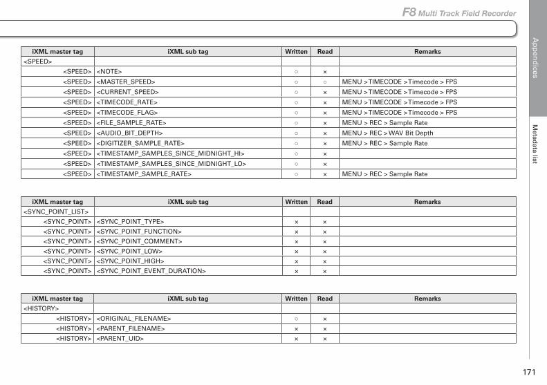
Ap
pen
dices
Metad
ata list
171
F8 Multi Track Field Recorder
iXML master tag iXML sub tag Written Read Remarks
<SPEED>
<SPEED> <NOTE> ○ ×
<SPEED> <MASTER_SPEED> ○ ○ MENU > TIMECODE > Timecode > FPS
<SPEED> <CURRENT_SPEED> ○ × MENU > TIMECODE > Timecode > FPS
<SPEED> <TIMECODE_RATE> ○ × MENU > TIMECODE > Timecode > FPS
<SPEED> <TIMECODE_FLAG> ○ × MENU > TIMECODE > Timecode > FPS
<SPEED> <FILE_SAMPLE_RATE> ○ × MENU > REC > Sample Rate
<SPEED> <AUDIO_BIT_DEPTH> ○ × MENU > REC > WAV Bit Depth
<SPEED> <DIGITIZER_SAMPLE_RATE> ○ × MENU > REC > Sample Rate
<SPEED> <TIMESTAMP_SAMPLES_SINCE_MIDNIGHT_HI> ○ ×
<SPEED> <TIMESTAMP_SAMPLES_SINCE_MIDNIGHT_LO> ○ ×
<SPEED> <TIMESTAMP_SAMPLE_RATE> ○ × MENU > REC > Sample Rate
iXML master tag iXML sub tag Written Read Remarks
<SYNC_POINT_LIST>
<SYNC_POINT> <SYNC_POINT_TYPE> × ×
<SYNC_POINT> <SYNC_POINT_FUNCTION> × ×
<SYNC_POINT> <SYNC_POINT_COMMENT> × ×
<SYNC_POINT> <SYNC_POINT_LOW> × ×
<SYNC_POINT> <SYNC_POINT_HIGH> × ×
<SYNC_POINT> <SYNC_POINT_EVENT_DURATION> × ×
iXML master tag iXML sub tag Written Read Remarks
<HISTORY>
<HISTORY> <ORIGINAL_FILENAME> ○ ×
<HISTORY> <PARENT_FILENAME> × ×
<HISTORY> <PARENT_UID> × ×
Metadata list (continued)
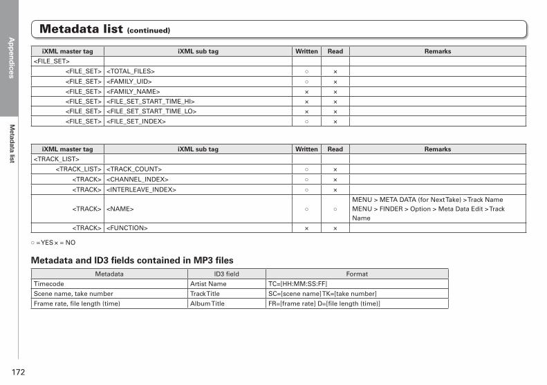
AppendicesM
etadata list
172
iXML master tag iXML sub tag Written Read Remarks
<FILE_SET>
<FILE_SET> <TOTAL_FILES> ○ ×
<FILE_SET> <FAMILY_UID> ○ ×
<FILE_SET> <FAMILY_NAME> × ×
<FILE_SET> <FILE_SET_START_TIME_HI> × ×
<FILE_SET> <FILE_SET_START_TIME_LO> × ×
<FILE_SET> <FILE_SET_INDEX> ○ ×
iXML master tag iXML sub tag Written Read Remarks
<TRACK_LIST>
<TRACK_LIST> <TRACK_COUNT> ○ ×
<TRACK> <CHANNEL_INDEX> ○ ×
<TRACK> <INTERLEAVE_INDEX> ○ ×
<TRACK> <NAME> ○ ○MENU > META DATA (for Next Take) > Track NameMENU > FINDER > Option > Meta Data Edit > Track Name
<TRACK> <FUNCTION> × ×
○ = YES × = NO
Metadata and ID3 fields contained in MP3 filesMetadata ID3 field Format
Timecode Artist Name TC=[HH:MM:SS:FF]
Scene name, take number Track Title SC=[scene name] TK=[take number]
Frame rate, file length (time) Album Title FR=[frame rate] D=[file length (time)]
Metadata list (continued)
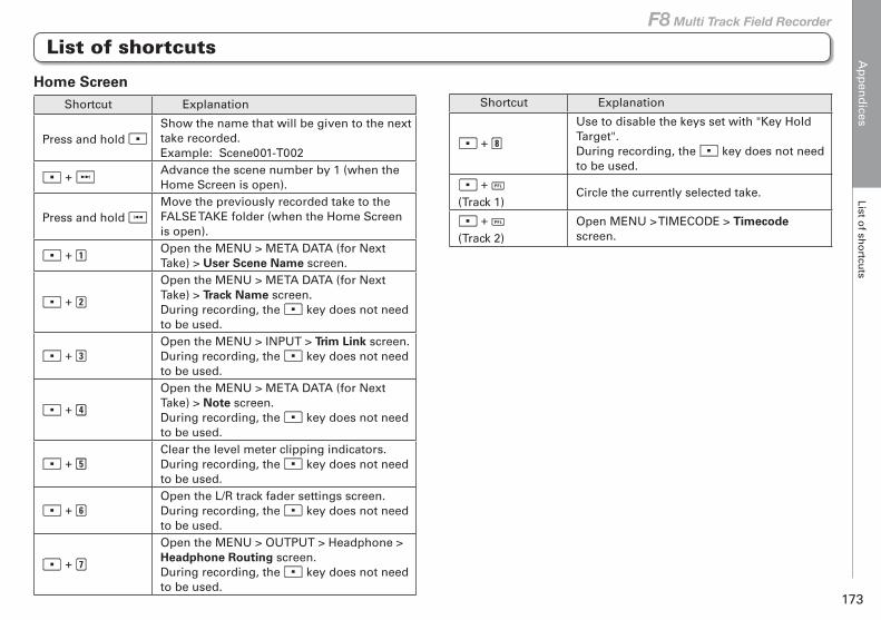
Ap
pen
dices
List of sh
ortcu
ts
173
F8 Multi Track Field Recorder
Home ScreenShortcut Explanation
Press and hold Show the name that will be given to the next take recorded.Example: Scene001-T002
+ Advance the scene number by 1 (when the Home Screen is open).
Press and hold Move the previously recorded take to the FALSE TAKE folder (when the Home Screen is open).
+ Open the MENU > META DATA (for Next Take) > User Scene Name screen.
+
Open the MENU > META DATA (for Next Take) > Track Name screen.During recording, the key does not need to be used.
+ Open the MENU > INPUT > Trim Link screen.During recording, the key does not need to be used.
+
Open the MENU > META DATA (for Next Take) > Note screen.During recording, the key does not need to be used.
+ Clear the level meter clipping indicators.During recording, the key does not need to be used.
+ Open the L/R track fader settings screen.During recording, the key does not need to be used.
+
Open the MENU > OUTPUT > Headphone > Headphone Routing screen.During recording, the key does not need to be used.
List of shortcuts
Shortcut Explanation
+
Use to disable the keys set with "Key Hold Target".During recording, the key does not need to be used.
+ (Track 1)
Circle the currently selected take.
+ (Track 2)
Open MENU > TIMECODE > Timecode screen.
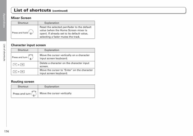
Ap
pen
dices
List of sh
ortcu
ts
174
Mixer ScreenShortcut Explanation
Press and hold
Reset the selected pan/fader to the default value (when the Home Screen mixer is open). If already set to its default value, selecting a fader mutes the track.
Character input screenShortcut Explanation
Press and turn Move the cursor vertically on a character input screen keyboard.
+ Delete a character on the character input screen.
+ Move the cursor to "Enter" on the character input screen keyboard.
Routing screenShortcut Explanation
Press and turn Move the cursor vertically
List of shortcuts (continued)
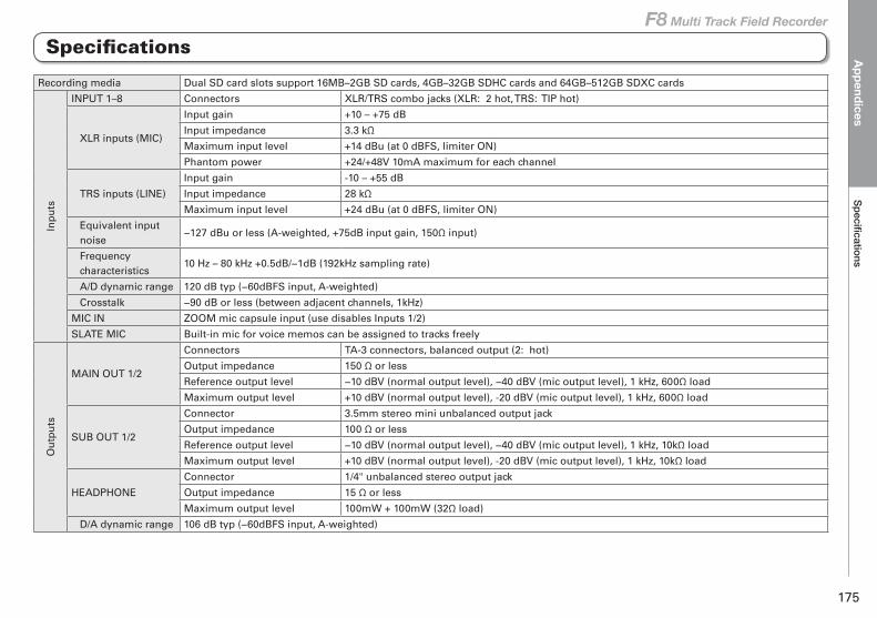
AppendicesSpecifications
175
F8 Multi Track Field Recorder
Recording media Dual SD card slots support 16MB–2GB SD cards, 4GB–32GB SDHC cards and 64GB–512GB SDXC cards
Inp
uts
INPUT 1–8 Connectors XLR/TRS combo jacks (XLR: 2 hot, TRS: TIP hot)
XLR inputs (MIC)
Input gain +10 – +75 dB
Input impedance 3.3 kΩ
Maximum input level +14 dBu (at 0 dBFS, limiter ON)
Phantom power +24/+48V 10mA maximum for each channel
TRS inputs (LINE)
Input gain -10 – +55 dB
Input impedance 28 kΩ
Maximum input level +24 dBu (at 0 dBFS, limiter ON)
Equivalent input noise
−127 dBu or less (A-weighted, +75dB input gain, 150Ω input)
Frequency characteristics
10 Hz – 80 kHz +0.5dB/−1dB (192kHz sampling rate)
A/D dynamic range 120 dB typ (−60dBFS input, A-weighted)
Crosstalk −90 dB or less (between adjacent channels, 1kHz)
MIC IN ZOOM mic capsule input (use disables Inputs 1/2)
SLATE MIC Built-in mic for voice memos can be assigned to tracks freely
Ou
tpu
ts
MAIN OUT 1/2
Connectors TA-3 connectors, balanced output (2: hot)
Output impedance 150 Ω or less
Reference output level −10 dBV (normal output level), −40 dBV (mic output level), 1 kHz, 600Ω load
Maximum output level +10 dBV (normal output level), -20 dBV (mic output level), 1 kHz, 600Ω load
SUB OUT 1/2
Connector 3.5mm stereo mini unbalanced output jack
Output impedance 100 Ω or less
Reference output level −10 dBV (normal output level), −40 dBV (mic output level), 1 kHz, 10kΩ load
Maximum output level +10 dBV (normal output level), -20 dBV (mic output level), 1 kHz, 10kΩ load
HEADPHONE
Connector 1/4" unbalanced stereo output jack
Output impedance 15 Ω or less
Maximum output level 100mW + 100mW (32Ω load)
D/A dynamic range 106 dB typ (−60dBFS input, A-weighted)
Specifications
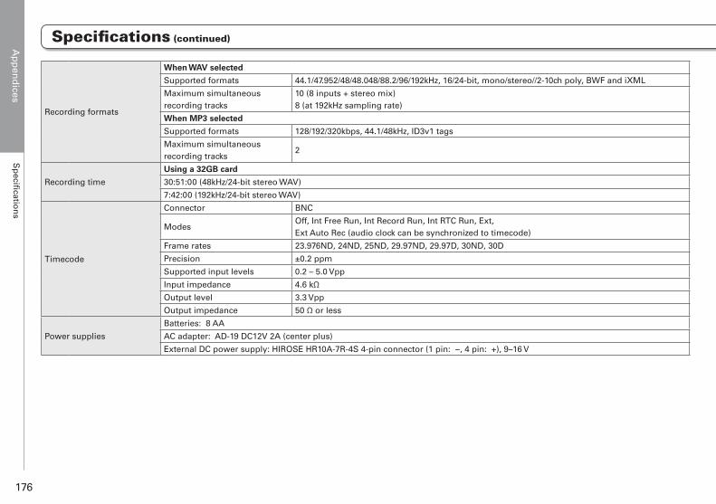
Ap
pen
dices
Sp
ecificatio
ns
176
Recording formats
When WAV selected
Supported formats 44.1/47.952/48/48.048/88.2/96/192kHz, 16/24-bit, mono/stereo//2-10ch poly, BWF and iXML
Maximum simultaneous recording tracks
10 (8 inputs + stereo mix)8 (at 192kHz sampling rate)
When MP3 selected
Supported formats 128/192/320kbps, 44.1/48kHz, ID3v1 tags
Maximum simultaneous recording tracks
2
Recording time
Using a 32GB card
30:51:00 (48kHz/24-bit stereo WAV)
7:42:00 (192kHz/24-bit stereo WAV)
Timecode
Connector BNC
ModesOff, Int Free Run, Int Record Run, Int RTC Run, Ext, Ext Auto Rec (audio clock can be synchronized to timecode)
Frame rates 23.976ND, 24ND, 25ND, 29.97ND, 29.97D, 30ND, 30D
Precision ±0.2 ppm
Supported input levels 0.2 – 5.0 Vpp
Input impedance 4.6 kΩ
Output level 3.3 Vpp
Output impedance 50 Ω or less
Power supplies
Batteries: 8 AA
AC adapter: AD-19 DC12V 2A (center plus)
External DC power supply: HIROSE HR10A-7R-4S 4-pin connector (1 pin: −, 4 pin: +), 9–16 V
Specifications (continued)
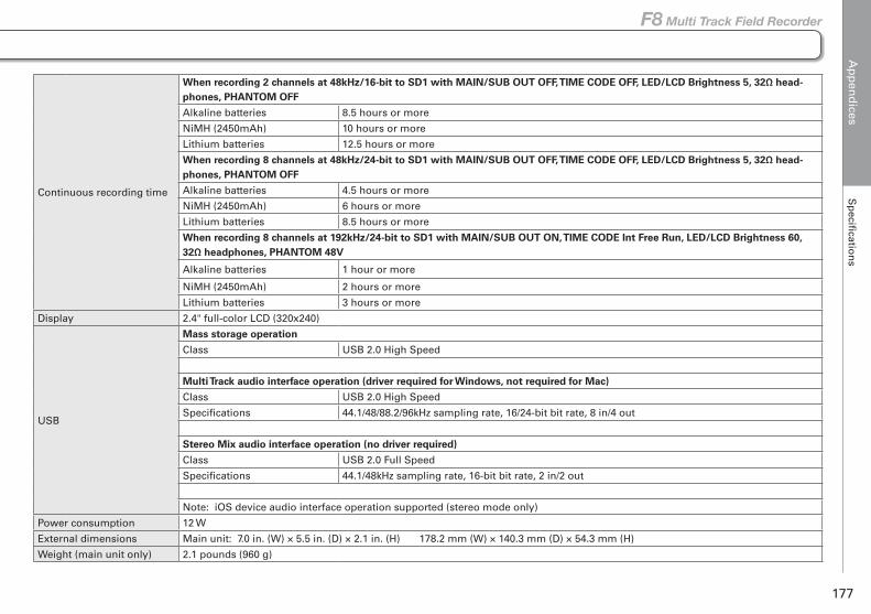
Ap
pen
dices
Sp
ecificatio
ns
177
F8 Multi Track Field Recorder
Specifications (continued)
Continuous recording time
When recording 2 channels at 48kHz/16-bit to SD1 with MAIN/SUB OUT OFF, TIME CODE OFF, LED/LCD Brightness 5, 32Ω head-phones, PHANTOM OFF
Alkaline batteries 8.5 hours or more
NiMH (2450mAh) 10 hours or more
Lithium batteries 12.5 hours or more
When recording 8 channels at 48kHz/24-bit to SD1 with MAIN/SUB OUT OFF, TIME CODE OFF, LED/LCD Brightness 5, 32Ω head-phones, PHANTOM OFF
Alkaline batteries 4.5 hours or more
NiMH (2450mAh) 6 hours or more
Lithium batteries 8.5 hours or more
When recording 8 channels at 192kHz/24-bit to SD1 with MAIN/SUB OUT ON, TIME CODE Int Free Run, LED/LCD Brightness 60, 32Ω headphones, PHANTOM 48V
Alkaline batteries 1 hour or more
NiMH (2450mAh) 2 hours or more
Lithium batteries 3 hours or more
Display 2.4" full-color LCD (320x240)
USB
Mass storage operation
Class USB 2.0 High Speed
Multi Track audio interface operation (driver required for Windows, not required for Mac)
Class USB 2.0 High Speed
Specifications 44.1/48/88.2/96kHz sampling rate, 16/24-bit bit rate, 8 in/4 out
Stereo Mix audio interface operation (no driver required)
Class USB 2.0 Full Speed
Specifications 44.1/48kHz sampling rate, 16-bit bit rate, 2 in/2 out
Note: iOS device audio interface operation supported (stereo mode only)
Power consumption 12 W
External dimensions Main unit: 7.0 in. (W) × 5.5 in. (D) × 2.1 in. (H) 178.2 mm (W) × 140.3 mm (D) × 54.3 mm (H)
Weight (main unit only) 2.1 pounds (960 g)

For U.S.A.FCC regulation warningThis equipment has been tested and found to comply with the limits for a Class B digital device, pursuant to Part 15 of the FCC Rules. These limits are designed to provide reasonable protection against harmful interference in a residential installation. This equipment generates, uses and can radiate radio frequency energy and, if not installed and used in accordance with the instructions, may cause harmful interference to radio communications. However, there is no guarantee that interference will not occur in a particular installation. If this equipment does cause harmful interference to radio or television reception, which can be determined by turning the equipment off and on, the user is encouraged to try to correct the interference by one or more of the following measures:
• Reorient or relocate the receiving antenna.• Increase the separation between the equipment and receiver.• Connect the equipment to an outlet on a circuit different from that to which
the receiver is connected.• Consult the dealer or an experienced radio/TV technician for help.
FCC CAUTIONChanges or modifications not expressly approved by the party responsible for compliance could void the user’s authority to operate the equipment.This transmitter must not be co-located or operated in conjunction with any other antenna or transmitter.
For U.S.A. and CANADAThis device complies with part 15 of the FCC Rules and Industry Canada license-exempt RSS standard(s). Operation is subject to the following two conditions:(1) This device may not cause harmful interference, and (2) this device must accept any interference received, including interference that may cause undesired operation.
This equipment complies with FCC/IC radiation exposure limits set forth for an uncontrolled environment and meets the FCC radio frequency (RF) Exposure Guidelines and RSS-102 of the IC radio frequency (RF) Exposure rules. This equipment has very low levels of RF energy that are deemed to comply without testing of specific absorption ratio (SAR).
Declaration of Conformity
For EU Countries
For CANADALe présent appareil est conforme aux CNR d’Industrie Canada applicables aux appareils radio exempts de licence. L’exploitation est autorisée aux deux conditions suivantes : (1) l’appareil ne doit pas produire de brouillage, et (2) l’utilisateur de l’appareil doit accepter tout brouillage radioélectrique subi, même si le brouillage est susceptible d’en compromettre le fonctionnement.
Cet équipement est conforme aux limites d’exposition aux rayonnements énoncées pour un environnement non contrôlé et respecte les règles d’exposition aux fréquences radioélectriques (RF) CNR-102 de l’IC. Cet équipement émet une énergie RF très faible qui est considérée conforme sans évaluation du débit d’absorption spécifique (DAS).
Label is located at the bottom of the unit.

Z2I-2914-01
ZOOM CORPORATION4-4-3 Kandasurugadai, Chiyoda-ku, Tokyo 101-0062 Japan
http://www.zoom.co.jp