Embed Size (px)
Citation preview
8/8/2019 Operation of the Unified Power Flow
http://slidepdf.com/reader/full/operation-of-the-unified-power-flow 1/9
116 IEEE TRANSACTIONS ON POWER ELECTRONICS, VOL. 11, NO . 6, NOVEMBER 1996
Operation of the Unified Power Flow
Controller as Harmonic IsolatorJohan H. R. Enslin, Senior Member, IEEE, Jian Zhao, and RenC SpCe, Senior Member, IEEE
Abstract-The unified power flow controller (UPFC) is a tool
in the implementation of Flexible AC Transmission Systems
(FACTS). It provides for the equivalent of static VAr compen-
sation and series injection using back-to-back force commutated
converters. This paper ]proposes a control strategy to extend
UPFC operation to allow for the isolation of harmonics due to
nonlinear loads. Simulation results based on the Electromagnetic
Transients Program (EMTP) are used to illustrate device per-
formance in a power system environment. Experimental results
based on a single phase laboratory implementation verify the
proposed control algorithm.
Ih
x,xX ,
LO
L ,CO
c,
Nonlinear load harmonic currents [A].
Transmission line reactance [Q].Equivalent series compensation reactance [RI .
Transformer leakage inductance [HI.
High frequency filter inductance [HI.
Passive harmonic filter inductances [HI.
High frequency filter capacitance [F].
Passive harmonic filter capacitances [F].
NOMENCLATUREFlexible AC Transmission Systems.
High voltage direct current transmission.
Thyristor controlled series compensator.
Unified power flow controller.
Static VAr compensator.
Insulated gatle bipolar transistor.
Injected series voltage [VI.
Sending-end transmission line voltage [VI.
Receiving-end transmission line voltage [VI
{BEFORE Hhrmonic Isolation}.
Isolated receiving-end voltage [VI
{AFTER Harmonic Isolation}.
Load-side receiving-end voltage [VI
{AFTER Harmonic Isolation}.
Injected voltage with series compensation [VI.
Injected voltage with angle compensation [VI.
Transmission line midpoint voltage [VI.
Converter dc bus voltage [VI.
Injected volttage with terminal
voltage compensation [VI.
Transmission power angle ["I .Transmission power angle between V, and V, [" I .Phase shift control angle ["I.Load thyristor firing angle ["I.UPFC shunt current source [A].
Load ac current [A].
Transmission line current [A].Passive filter current [A].
I. INTRODUCTION
ONCEPTS relating to Flexible AC Transmission Sys-tems (FACTS) are gaining popularity internationally for
enhancing steady-state power transfer limits as well as improv-
ing power system dynamic response [1]-[S]. FACTS devices
include solid-state phase shifters [11, 121, thyristor-controlled
series capacitors [ 3 ] , 4], and static VAr devices [SI, [6]. First
generation installations using phase controlled series compen-
sators are currently being commissioned [4], [14]. Recent
efforts have addressed the synthesis of FACTS controllers
using converter-based topologies. The unified power flow
controller (UPFC) [SI-[7] provides for the equivalent of static
VAr compensation and series injection using back-to-back
force-commutated converters [6], [7].With an increasing em-
phasis on power quality [E], [12], harmonic isolation [8]-[111,
and harmonic compensation [12], [13] issues are also being
investigated for high power applications [12], [13].
The present paper discusses the extension of UPFC opera-
tion to include not only fundamental phase shift and reactive
power compensation, but to also provide for harmonic isolation
in the presence of nonlinear loads. This is performed using a
combined harmonic/fundamental control strategy in a single
converter topology. This approach allows for the optimum
use of installed converter kVA with a potentially attractive
cost/performance characteristic. Simulation results using the
electromagnetic transients program (EMTP) illustrate device
performance of a 120 kVA converter implementation. Thisconverter system is suitable for a 1.3 MVA nonlinear load,
implementing both fundamental phase shift and harmonicisolation. Experimental results are presented for a low power,
Manuscript received July 18, 1994; revised June 9, 1996. A version of thispaper was presented at the 1994 Power Electronics Specialists Conference.This work was supported by ESKOM and the FRD.
J. H. R. Enslin is with the Department of Electrical and Electronic
J . Zhao is with the Department of Electrical and Electronic Engineering,
R. Sp6e is with the Department of Electrical and Computer Engineering,
sing1e phase laboratory prototype' Both and lab-
oratory data show the capability of the proposed combined
control approach.
device an d micro-contro11er de -
velopments make this new principle already applicable to
the multi-megawatt power range. Some first applications to
be considered are controlling power flow and stabilizing
distribution networks in the presence of harmonic generating
Engineering, University of Stellenbosch, 7600, Stellenbosch, South Africa.
University of Stellenbosch, 7600, Stellenbosch, South Africa.
Oregon State University, Corvallis, OR 97331 USA.Publisher Item Identifier S 0885-8993(96)06856-1.
"ITent power
0885-8993/96$05.00 0 996 IEEE
Authorized licensed use limited to: Jawaharlal Nehru Technological University. Downloaded on July 21, 2009 at 05:23 from IEEE Xplore. Restrictions apply.
8/8/2019 Operation of the Unified Power Flow
http://slidepdf.com/reader/full/operation-of-the-unified-power-flow 2/9
ENSLIN et al.: OPERATION OF UNIFIED POWER FLOW CONTROLLER
Modes of Operation
1) No Compensation
2) Series Compensation
3) Shunt Compensation
4) Phase ShiftControl
171
Power Controller Output
v, 1
0 0
-jX;I, 0
0 -jllV/X(l-cos 6/2)
*jV, tana No Reactive Current
A s 2
Fig. 1. FACTS with phase shifter.
PS
industrial loads. Transmission system applications to be con-
sidered include the isolation of harmonic power flows and the
stabilization of geographically separate power systems.
11. UNIFIEDPOWER ONTROL ONCEPTS
A . Flexible AC Transmission (FACTS)
Consider power flow over an ac line, in (1) and Fig. 1
V s .Vrp=- .sin S,, .
* S
The power flow depends on transmission angle, S,,, be-
tween the line-end voltages, the sending-end voltage, V,, the
receiving-end voltage, V,, and line impedance, X,. Currently,
only limited high speed control over any one of these parame-
ters is used. In electromechanically controlled power systems,
the operators arrive at the required steady-state power flow
while maintaining voltages and angles within safe tolerable
limits. These levels are well below the peak stability limits
of the power system. The consequences of the lack of fast,
reliable control are stability problems, power flowing through
other than the intended lines, the inability to fully utilize the
transmission resources to their thermal and/or economic limits,
undesirable VAr flows, higher losses, bad voltage regulation,cascade tripping, and long restoration times [l], 121.
Fig. 1 shows a representation of a phase shifter in one
transmission line. This phase shifter can be realized with a high
speed thyristor based converter [11, 151.With this arrangement,one can obtain substantially the same advantages as with an
HVDC line but at a fraction of the cost, since not all power is
processed through the power electronic converter. This phase
controller forms the basis of the UPFC [SI. All the network
parameters in (1) can now be controlled by means of this
equivalent UPFC.
(a)
- a n n+a2
(b)
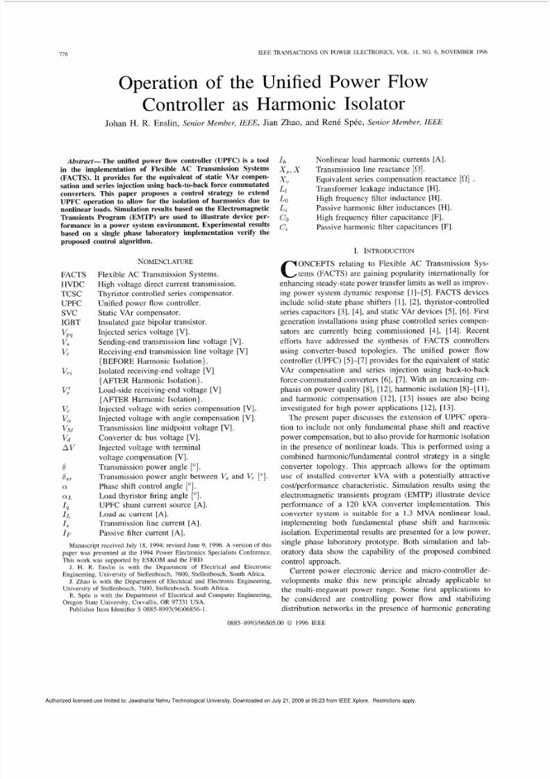
Equivalent circuit and operating modes of the UPFC [ 6 ] .ig. 2.
B. Basic Principle o UPFC Operation
The basic equivalent circuit of the UPFC is shown in Fig. 2.
A fully controllable voltage source, V,,, is injected in series
with the transmission line, and a controllable shunt current
source, I,, is connected in parallel with the transmission line.
The modes of operation are summarized in Fig. 2(b). For
generalized series (shunt) compensation, the source 1, (V,,)
could be omitted if a sufficient dc energy storage device wascoupled to the controlled voltage (current) source. The UPFC
then operates either as a converter-based series compensator
or static VAr compensator [61, 171.
The different UPFC modes of operation are plotted in
the power flow diagram, depicted in Fig. 2(b), while the
appropriate values for Iq and V,, are shown in Table I [6].
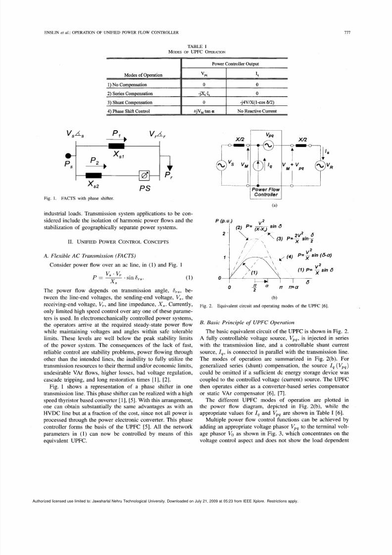
Multiple power flow control functions can be achieved by
adding an appropriate voltage phasor V,, to the terminal volt-
age phasor VO s shown in Fig. 3, which concentrates on the
voltage control aspect and does not show the load dependent
Authorized licensed use limited to: Jawaharlal Nehru Technological University Downloaded on July 21 2009 at 05:23 from IEEE Xplore Restrictions apply
8/8/2019 Operation of the Unified Power Flow
http://slidepdf.com/reader/full/operation-of-the-unified-power-flow 3/9

8/8/2019 Operation of the Unified Power Flow
http://slidepdf.com/reader/full/operation-of-the-unified-power-flow 4/9
ENSLIN et al.: OPERATION OF UNIFIED POWER FLOW CONTROLLER
Extended Modes of Operation
5 ) Harmonic Isolation
179
Power Controller Output
"m 4
4.1, 0
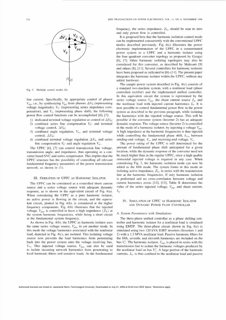
(c )
Fig. 4. UPFC as harmonic isolator: (a) equivalent circuit, (b) principle of operation, and (c) power electronics implementation.
Transm. Line Ind L,
UPFC Filter Ind. Lo
Trans. 2 Leakage
Load RL *
Load Ind. L,
UPFC Filter Cap. CO
Trans. 2 Wind. Ratio0 pH
82-84"
* RL s adjusted to keep load current, ILdoconstant (83 Adc)
filters, Cf and L f . It is assumed that the dc link voltage inthe UPFC circuit is kept constant at 400 V by Inverter 1.
To simulate the circuit under the same defined conditions, the
load current IL, filter current I F ,and line current I , are kept
constant. The sending-end voltage, V,, is also kept constant
at 6.35 kV (rms). The load current is the current produced
by the phase controlled rectifier circuit. A clean sinusoidal
voltage at V, is assumed on the sending-end power bus. The
main parameters of the simulations are shown in Table 111.
Case 1-Small Phase Compens ation and Harm onic Isola-
tion: No fundamental phase shift between VTi and v! s
implemented in the controller of the UPFC for the firstsimulation case. Thus, the UPFC is operating mainly asharmonic isolator. The EMTP output is plotted in Fig. 5. For
this case, the power rating of the UPFC (Inverter 2) is very
small compared to the transmission rating. The waveformof V,, still has a small fundamental component, which is
included to compensate for the internal leakage reactance of
the injecting transformer, Tr2. The load voltage V, before
harmonic isolation (resulting from the six-pulse load converter
and network impedance X , ) exhibits the well-known distortion
of fifth, seventh, eleventh, thirteenth, etc., harmonics.
Authorized licensed use limited to: Jawaharlal Nehru Technological University Downloaded on July 21 2009 at 05:23 from IEEE Xplore Restrictions apply
8/8/2019 Operation of the Unified Power Flow
http://slidepdf.com/reader/full/operation-of-the-unified-power-flow 5/9
780
Description
Load Apparent
Power [S,]
Load ActivePowe r [P,]
Transmission
Apparent Pow er
UPFC Inv. 2
Power Rating
UPFC Inv. 1
Power Rating
Passive Filters
Eqv. Impd. Z,
IEEE TRANSACTIONS ON POWER ELECTRONICS, VOL 11 , NO . 6, NOVEMBER 1996
No (i) Harmonic (ii) Phase Contr .
Compensation Isolation & Harm. Iso.
1.27 MVA 1.28 MVA 1.04 MV A
140 kW 173 kW 104 kW
1.27MVA 602 kVA 602 kVA
0 7 kVA 120 kVA (Rect.)
0 0 36 kVA (Inv.)
0 770 kVA 625 kVA
X, 1.88 Q X, 1.88 Q Z, = 1 2 j 3 8 Q
TABLE IVRELATIVE OWE RCA LCU LA TIO N S
t - --I0 10 20 30 40
f(ms)
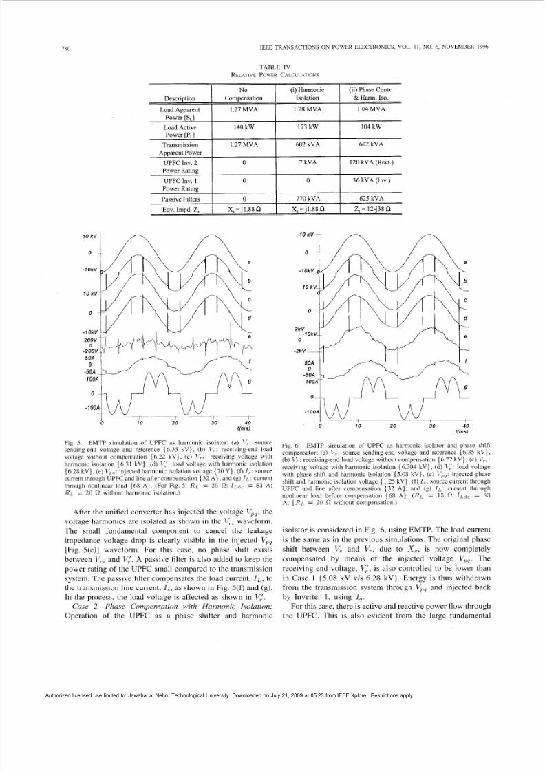
Fig. 5 . EMTP simulation of UPFC as harmonic isolator: (a) I:: sourcesending-end voltage and reference {6.35 kV} , (b) 1’; : receiving-end loadvoltage without compensation {6.22 kV}, (c ) VrZ: eceiving voltage withharmonic isolation 16.31 kV}, (d) I);!: load voltage with harmonic isolation{ 6.28 kV} , (e) injected harmonic isolation voltage (7 0 V} , (f) I, : sourcecurrent through UPFC and line after compensation { 32 A } , and (g) I L : currentthrough nonlinear load {68 A]. (For Fig. 5 : RL = 25 n: I L ~ < 8 3 A:
RJ,= 20 C without harmonic isolation.)
After the unified converter has injected the voltage Vpq,he
voltage harmonics are isolated as shown in the V,,waveform.The small fundamenlal component to cancel the leakage
impedance voltage drop is clearly visible in the injected V,,
[Fig. 5(e)] waveform. For this case, no phase shift exists
between V,, nd V:.A passive filter is also added to keep the
power rating of the UPFC small compared to the transmission
system. The passive filter compensates the load current, IL , o
the transmission line current , I s ,as c,hown in Fig. 5(f) and (g).
In the process, the load voltage is affected as shown in V:.
Case 2-Phase Com pensation with Harm onic Isolation:
Operation of the UPFC as a phase shifter and harmonic
‘ 0 10 20 30 40
tfms)
Fig. 6. EMTP simulation of UPFC as harmonic isolator and phase shiftcompensator: (a) IT,: ource sending-end voltage and reference { 6.3.5 kV},(b ) V,: receiving-end load voltage without compensation (6.22 kV}, (c ) VrZ:receiving voltage with harmonic isolation { 6.304 kV}, (d ) V load voltagewith phase shift and harmonic isolation (5.08 kV} , (e) injected phaseshift and harmonic isolation voltage { 1.25 kV}, (f) I,? source current throughUPFC and line after compensation (3 2 A} , an d ( 8 ) I L : current throughnonlinear load before compensation (68 A } . (RL = 1 5 0 : 1 ~ ~ 1 ~83
A: {RL 2 0 s2 without c ompensation.)
isolator is considered in Fig. 6, using EMTP. The load current
is the same as in the previous simulations. The original phase
shift between V, and V,, due to X , , is now completely
compensated by means of the injected voltage Vpq.The
receiving-end voltage, Vi, s also controlled to be lower than
in Case 1 (5.08 kV vls 6.28 kV}. Energy is thus withdrawn
from the transmission system through V,, and injected back
by Inverter 1, using Iq .
For this case, there is active and reactive power flow through
the UPFC. This is also evident from the large fundamental
Authorized licensed use limited to: Jawaharlal Nehru Technological University. Downloaded on July 21, 2009 at 05:23 from IEEE Xplore. Restrictions apply.
8/8/2019 Operation of the Unified Power Flow
http://slidepdf.com/reader/full/operation-of-the-unified-power-flow 6/9
ENSLIN et al.: OPERATION OF UNIFlED POWER FLOW CONTROLLER
Transm. Line Ind L, 11.9m H
UPFC Filter Ind Lo
Trans. 2 Leakage L,
56 pH
12 pH
Nom. Load Current I, 5 A
3rd Passive Filter 42 pF
27 mH
781
Load Ind. LL 28 mH
UPFC Filter Cap CO 800pF
Trans. 2 Turn Ratio 1:2.13
Nominal Voltage V, 22 0 v
5th Passive Filter 7.1 pF
57 mH
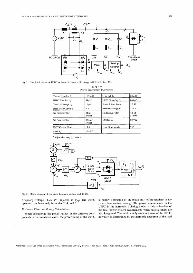
Fig. 7. Simplified circuit of UPFC as harmonic isolator (dc energy added at dc bus, Vd).
IGBT Current Limit 10 A Load Firing Angle 95"
7th Passive Filter 3.56 pF 11 DC Bus V, I50 Vdc
15 7 m~
Load RL' 110-1662 11'Adjusted to keep I, constant
+Vd
T2&- T ,,O o I 7 $ ~i 2
IGBTInv.2S0
- 4l VPq
Fig. 8. Block diagram of simpli stic harmonic isolator and UPFC.
frequency voltage { 1.25 kV} injected at Vpq.The UPFC
operates simultaneously in modes 2, 4, and 5.
B. Power Flow and Rating Calculations
When considering the power ratings of the different com-
ponents in the simulation cases, the power rating of the UPFC
is mainly a function of the phase shift effort required in the
power flow control strategy. The power requirements for the
UPFC in the harmonic isolating mode is only a fraction of
the total power system requirements when passive filters are
also integrated. The minnmum dynamic response of the UPFC,
however, is determined by the harmonic spectrum of the load
Authorized licensed use limited to: Jawaharlal Nehru Technological University. Downloaded on July 21, 2009 at 05:23 from IEEE Xplore. Restrictions apply.
8/8/2019 Operation of the Unified Power Flow
http://slidepdf.com/reader/full/operation-of-the-unified-power-flow 7/9
782 IEEE
to be isolated. Table IV shows the power flows and rating
requirements for Invertiers 1 and 2 in the different simulation
cases. In Case ii, the eiquivalent network impedance, Z,,as
a resistive and capacitive portion, which indicates the amount
of active power removed from the system at point V.,, and
injected back by means of I q .
v. EXPEIRIMENTAL VERIFICATION
A. Power Electronic System f o r Experimental Verification
To evaluate the concept of harmonic isolation using a unified
power controller experimentally, a small single phase exper-
imental UPFC has been developed using an IGBT inverter.
The basic experimental converter system is shown in Fig. 7
and represents a portion of the system shown in Fig. 4(c). In
Fig. 7, energy is added at the dc bus to maintain a constant
link voltage, V d .
The parameters of the experimental system are included
in Table V and refer to Figs. 7 and 4(c). Only Inverter
2, reference to Fig. 4(c), is integrated using IGBT devices
with associated gate-drives and controllers. The active poweris directly supplied to1 the dc bus V d , from a separate dc
power supply. Due to the harmonic isolator topology and
series transformer, a half-bridge power electronic converter
implementation was adequate for this application. The IGBT
inverter is rated for 100 V, 10 A. Controller inputs are the
desired angle, S , and Ithe instantaneous values of sending-end
voltage, v, ( t ) , nd receiving-end voltage, vT z t ) . he passive
filters are designed as tuned harmonic traps for the third, fifth,
and seventh current harmonics and are connected on the load
voltage bus Vi.The single phase implementation also requires
a third harmonic passive filter.
B. Controller fo r UPFC as Harmonic Isolator
A simple analog controller was implemented to derive the
reference signal for ' u ~ ( ~t ) . he block diagram for this simple
controller is shown in Fig. 8. Inputs to the controller are the
angle reference S:,, the receiving-end voltage, v,(t), and the
sending-end voltage, v s ( t ) .The control function is shown in
(2).
vpq( t ) A . sin(& + &,) - B . v.(t)
A;B = Constants. (2)
The inner control loops shown in Fig. 8 force the reference
voltage and current to the desired values.
Case I-UPFC as Harmonic Isolator: No fundamentalphase shift = 0) is implemented to illustrate the UPFC
as a harmonic isolator. There is therefore no compensation of
the line impedance X , , and the experimental results in Fig. 9
show the operation of the UPFC mainly as harmonic isolator.
In most cases the frequency spectra (in dB) of the waveforms
are also included to indicate the effect of the harmonic isolator
on the waveforms. For this case, the power rating of the UPFC
is very small compareld to the rating of the transmission line
since mainly harmonic isolation is considered. This operating
mode corresponds to the defined mode 5 in Table 11, and
TRANSACTIONS ON POWER ELECTRONICS, VOL. 11 , NO . 6, NOVEMBER 1996
-
. . . . . . . . . . . . . . . . . . . . . . . . . . . . . . . . . . ..................... ................................ . .
. . . . . . . > . . . . . . . . . . . . . . . . : . . . . . .i . . . . . . . . . . . . .. ...................
(d )
L t , s
( e ) (f)
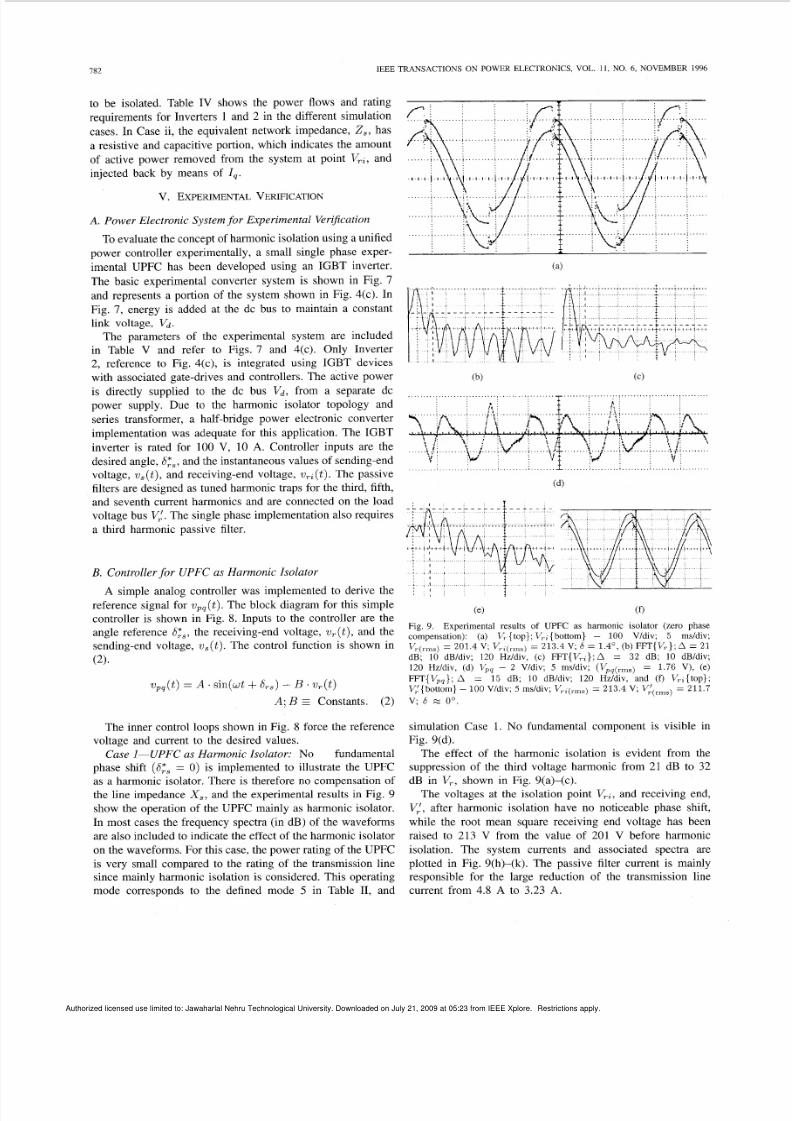
Fig 9 Expenmental results of UPFC as harmonic isolator (zero phasecompensation) (a) V, top}, V,,{bottom} - 100 V/div, 5 mddiv,
dB, 10 dB/dlv; 120 Hz/dlv, (c) FFT{VrZ};A = 32 dB, 10 dB/dlv;120 Hz/div, (d) V,, - 2 V/div, 5 ms/div; (Vpq(rms) = 1 76 V) , ( e )
FFT{V,,}, A = 1 5 dB, 10 dB/div, 120 Hz/div, and (f) V,,{top},
V,'{bottom} - 0 0 V/div, 5 ms/div, V,,,,,,) = 2 13 4 V; Vi(rms)= 2 1 1 7
V,,,,,) = 2 01 4 V , VT/7L(rrllb)21 3 4 V , 5:4 O , (b) F F T{V T} ,A = 21
v, 6 E oo
simulation Case 1. No fundamental component is visible in
Fig. 9(d).
The effect of the harmonic isolation is evident from thesuppression of the third voltage harmonic from 21 dB to 32
dB in V,, shown in Fig. 9(a)-(c).
The voltages at the isolation point V,,, and receiving end,
Vi, after harmonic isolation have no noticeable phase shift,
while the root mean square receiving end voltage has been
raised to 213 V from the value of 201 V before harmonic
isolation. The system currents and associated spectra are
plotted in Fig. 9(h)-(k). The passive filter current is mainly
responsible for the large reduction of the transmission line
current from 4.8 A to 3.23 A.
Authorized licensed use limited to: Jawaharlal Nehru Technological University. Downloaded on July 21, 2009 at 05:23 from IEEE Xplore. Restrictions apply.
8/8/2019 Operation of the Unified Power Flow
http://slidepdf.com/reader/full/operation-of-the-unified-power-flow 8/9
ENSLIN et al.: OPERATION OF UNIFIED POWER FLOW CONTROLLER 783
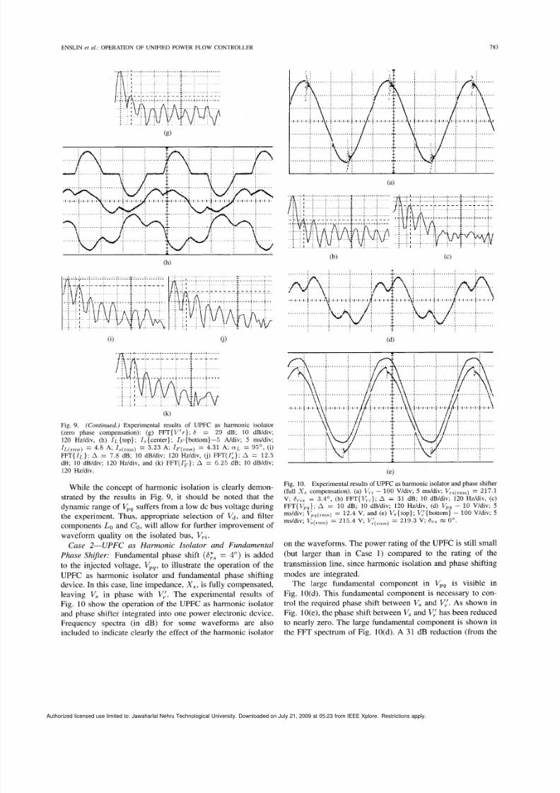
(k)
Fig. 9. (Continued.) Experimental results of UPFC as harmonic isolator(zero phase compensation): (g) FFT{V'r}; 6 = 29 dB ; 10 dB/div;120 Hz/div, (h) I L {top}; I , {center}; I~{bottom}-5 Ndiv; 5 ms/div;IL( rms )4.8 A ; I,(,,,,,) = 3.23 A; IF(,,n,) = 4 . 3 1 A; CYL= 95', (i)
FFT{IL}; A = 7. 8 dB; 10 dB/div; 120 Hz/div, (i) FFT(IA}; A = 1 2 . 5dB; 10 dB/div; 1 20 Hz/div, and (k) FFT(I&}; A = 6.25 dB ; 10 dB/div;
120 Hz/div.
While the concept of harmonic isolation is clearly demon-
strated by the results in Fig. 9, it should be noted that the
dynamic range of V,, suffers from a low dc bus voltage during
the experiment. Thus, appropriate selection of V d , and filter
components Lo and CO , ill allow for further improvement of
waveform quality on the isolated bus, VTt.Case 2-UPFC as Harmonic Isolator and Fundamental
Phase Shifter: Fundamental phase shift (S:, = 4") is added
to the injected voltage, Vpq,o illustrate the operation of the
UPFC as harmonic isolator and fundamental phase shifting
device. In this case, line impedance, X , , is fully compensated,
leaving V , in phase with V:. The experimental results of
Fig. 10 show the operation of the UPFC as harmonic isolator
and phase shifter integrated into one power electronic device.
Frequency spectra (in dB) for some waveforms are also
included to indicate clearly the effect of the harmonic isolator
(e )
Fig. 10. Experimental results of UPFC as harmonic isolator and phase shifter(full X , compensation). (a) Kt - 100 V/div; 5 ms/div; V,,(,,,) = 217.1
V ; 6,,, = 3.4', (b) FFT{VTi}) ;A = 31 dB; 10 dB/div; 120 Hz/div, (c)
FFT{V,,}; A = 1 0 dB; 10 dB/div; 120 Hz/div, (d) V, - 10 V/div; 5ms/div; l'p/ps(rms)12 .4 V, and ( e ) V,{top}; VT/,l{bottom}- 00 V/div; 5
ms/div; V,(,,,,,, = 215.4 V; V:,rIr,s, = 2 1 9 . 3 V ; 6,, % 0'.
on the waveforms. The power rating of the UPFC is still small
(but larger than in Case 1) compared to the rating of the
transmission line, since harmonic isolation and phase shifting
modes are integrated.
The large fundamental component in V,, is visible in
Fig. 10(d). This fundamental component is necessary to con-
trol the required phase shift between V, and Vi. As shown in
Fig. 10(e), the phase shift between V, and Vi has been reduced
to nearly zero. The large fundamental component is shown in
the FFT spectrum of Fig. 10(d). A 31 dB reduction (from the
Authorized licensed use limited to: Jawaharlal Nehru Technological University Downloaded on July 21 2009 at 05:23 from IEEE Xplore Restrictions apply
8/8/2019 Operation of the Unified Power Flow
http://slidepdf.com/reader/full/operation-of-the-unified-power-flow 9/9
184 IEEE TRANSACTIONS ON POWER ELECTRONICS, VOL. 11 , NO . 6, NOVEMBER 1996
original 21 dB) of the voltage harmonics is still maintained in
this mode of operation while performing fundamental phase
shift control. System currents are maintained at the same levels
as in the previous test case of Fig. 9.
VI. SUMMARY AND RECOMMENDATIONS
The UPFC provides; for excellent control flexibility in ac
transmission systems by allowing for static VAr compensation,
series compensation, and phase shift using the same installed
power electronic hard,ware. The present paper has extended
UPFC operation to provide for harmonic isolation in the pres-
ence of nonlinear loads. EMTP studies outline the principle
of operation for pure isolation purposes and mixed-mode op-
eration. The latter mode incorporates harmonic isolation with
the traditional UPFC modes of operation. Experimental results
are provided for a low power laboratory prototype. While the
practical results shown, are far from optimum, they serve well
to illustrate the concept developed. Future work will address
the optimization of isolation performance by improving theUPFC dynamic range. Three phase implementations at more
realistic power ratings will also be investigated.
As illustrated in the paper, the UPFC does not require a
substantial increase in converter kVA to isolate significant
harmonic loads when used in conjunction with appropriate
passive filters. For example, a converter rating of 120 kVA
was shown to be suitable for harmonic isolation of a 1.3 MVA
load while providing for fundamental phase shift and voltage
control of 0.2 p.u. Thus, UPFC operation including harmonic
isolation provides for the optimum use of installed converter
kVA and offers potentially attractive cosVperformance ratios.
Present day power device limitations will initially limit the
UPFC harmonic isolator concept to several MVA to achieve
the desired switching frequencies of several kHz. There are
numerous applications at the distribution level as well as
for industrial loads, however, where this concept can already
be implemented. Eventually, converter implementations seem
feasible for high power applications, such as isolation of
harmonics between two power systems while providing for
fundamental power flow control. Future work will address
application specific design advantages and tradeoffs for the
UPFC when compared to other, more conventional FACTS
devices, such as the TCSC. For example, the absence of
capacitor based subs,ynchronous resonance may make the
UPFC with harmonic: isolation capability a very attractive
candidate for systems with high levels oE thermal generation
in the presence of high power nonlinear loads, such as arc-
furnaces.
ACKNOWLEDGMENT
The authors gratefully acknowledge the contributions of J .
Beukes.
REFERENCES
N. G. Hingora ni, “FACTS-Flexible AC transm ission system,” in P roc.
Fifth 1991 IE E Int. Conf AC an d D C Power Transmission, London,U.K., Sept. 17-20, 1991, pp. 1-7.__ , “FACTS-Flexible AC transmission system,” presented at EPRIWorkshop on FACTS, Cincinnati, OH, Nov. 14-16, 1990..I. rbanek, R. J. Piwko, E. V. Larsen, B. L. Damsky, B. C. Furumasu,
W. Mittelstadt, and J. Eden, “Thyristor controlled series compensationprototype installation at the slatt 500 kV substation,” IEEE Trans. Power
Delivery, pp. 1460-1469, July 1993.W. A. Mittelstadt, “Considerations in planning use of FACTS devices ona utility system,” presented at EPRI Workshop on FACTS, Cincinnati,OH , Nov. 14-16, 1990.L. Gyugyi, “Unified power-flow control concept fo r flexible AC trans-mission systems,” Proc. Inst. Elec. Eng., vol. 139, pt. C, no. 4, pp.323-331, July 1992.~, “Dynamic compensation of AC transmission lines by solid-state synchronous voltage sources,” presented at the 1 993 IEEE Pow er
Engineering Summer Meeting, Vancouver, Canada, July 1993, no. 93SM 434-1 PWRD.~, “Solid state control of AC power transmission,” presented at theEPRI Workshop on FACTS, Cincinnati, OH , Nov. 14-16, 1990.F. 2. Peng, H. Akagi, and A. Nabae, “Compensation characteristics ofthe combined system of shunt and series active filters,” IEEE Trans. Ind.
Applicar., vol. 29, no. I , pp . 144-152, JadFeb. 1993.N. alboa, D. Sella, R. Penzo, B . Bisiach, D. Cappellieri, L. Malesani,
and A. Zuccato, “Hybrid active filter for parallel harmonic compensa-tion,” in Proc. European Power Electronics Con$, 1993, pp. 133-138.S. Bhattacharya, D. M. Divan, and B. B. Banerjee, “Synchronous frameharmonic isolator using active series filter,” in Proc. EPE-91 Con$,
Firenze, Italy, Oct. 1991.-, “Control and reduction of terminal voltage total harmonicdistortion (THD) in a hybrid series active and parallel passive filtersystem,” in Proc. PESC -93 Con$, Seattle, WA, June 20-24, 199 3.J. H. R. Enslin, J . D. Van Wyk, and M. NaudC, “Adaptive, closed-loopcontrol of dynamic pow er filters as fictitious power com pensators,” IEEE
Trans. hd . lectron., vol. 37, no. 3, pp. 203-211, June 1990.G. L. Van Harmelen and J. H. R. Enslin, “Real-time, dynamic controlof dynamic power filters i n supplies with high contamination,” IEEE
Trans. Power Electron., vol. 8 , no. 3, pp. 301-308, July 1993.Y . Wang, R. R. Mohler, R. SpCe, and W. Mittelstadt, “Variable structureFACTS controllers for power system transient stability,” IEEE Trans.
Power Syst. , vol. 7, no. I , pp. 307-313, 1992.
Johan H. R. Enslin (M’85-SM’92), fo r a photograph and biography, see p.697 of the September I996 issue of th is TRANSA CTIONS.
Jian Zhao received the M.S. degree from the Insti-tute of Special Electrical Machines at the ShenyangPolytechnic University, Shenyang, P.R. China, in1988.
From 1988 to 1991 he was a Lecturer at theDalian Institute of Technology, Dalian, P.R.C. Dur-ing 1991, he was a Research Assistant at the Univer-sity of Catania in Italy. In 1992 he was a ResearchAssistant at the University of Cape Town in SouthAfrica. Since 19 92, he has been a Ph .D. student at
the University of Stellenbosch in South Africa. Hisresearch interests include PM m otors, linear induction motors, DSP control ofsynchronous reluctance drives, and flexible ac transmission systems.
Ren6 Sp6e (S’84-M’%-SM’92), for a photograph and biography, see p. 697of the September 1996 issue of th is TR ANSACTIONS.