Embed Size (px)
Citation preview
MEASURING COMPANYVavdi Sr No. 17, Plot No 55B, Rani Industrial Estate, Gondal Road, Rajkot-360 002. India. Tel : +91 281 2925530, Email : [email protected] Web : www.forkmeasuring.com
OPERATIONAL MANUALFOR
MODEL:LMM - 600
LMM600 Page2
CONTENTS
Unpacking and installa�on direc�on for the user
1. Uses
2. Specifica�ons
3. Measuring principles
4. Structure
5. Method of opera�on
6 Maintenance
Safe and earthed power source are required to be provided!
__________________________________________________________________________
Along with the upgrade of the product, certain content of the Opera�on Manual may be revised,
excuse for not being no�fied later.
LMM600 Page3
Unpacking and installation direction to the user
1. Illustration
Before unpacking and installing the instrument, read the following direc�ons carefully and do by
steps in order to guarantee the accuracy of the instrument.
2. The sequence of the unpacking and installation
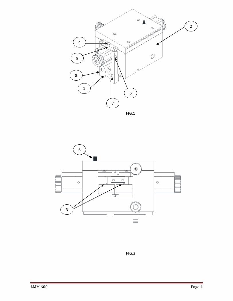
2.1 Take down the four screws 1 # which fasten the box, move out the Abbe measuring unit 2#
completely (Fig. 1).
2.2 Open the front cover 8# of the Abbe measuring unit and remove the screws 3#, then close
the front cover (Fig. 2).
2.3 Release two screws 4# in right and le� a li�le, then two screws 5#, firstly remove two screws
4# and then two screws 5#
A�en�on : When removing the screws 4# and 7#, it should be done in the mean�me.
2.4 Locking screw 6#, support the Abbe unit 2# with two hands. Take out four screws 7 #. Take
out 8#, 9# in a whole.
2.5 Take out the bed of the instrument from the box, and mount three foot -screws under it.
2.6 Place the Abbe unit and the tailstock on the bed respec�vely. So the complete the unpacking
and installing of the instrument.
LMM600 Page4
FIG.1
FIG.2
1
2
3
4
5
6
7
8
9
LMM600 Page5
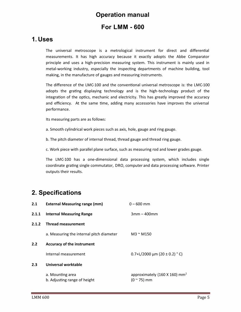
Operation manual
For LMM - 600
1. Uses
The universal metroscope is a metrological instrument for direct and differen�al
measurements. It has high accuracy because it exactly adopts the Abbe Comparator
principle and uses a high-precision measuring system. This instrument is mainly used in
metal-working industry, especially the inspec�ng departments of machine building, tool
making, in the manufacture of gauges and measuring instruments.
The difference of the LMC-100 and the conven�onal universal metroscope is: the LMC-100
adopts the gra�ng displaying technology and is the high-technology product of the
integra�on of the op�cs, mechanic and electricity. This has greatly improved the accuracy
and efficiency. At the same �me, adding many accessories have improves the universal
performance.
Its measuring parts are as follows:
a. Smooth cylindrical work pieces such as axis, hole, gauge and ring gauge.
b. The pitch diameter of internal thread, thread gauge and thread ring gauge.
c. Work piece with parallel plane surface, such as measuring rod and lower grades gauge.
The LMC-100 has a one-dimensional data processing system, which includes single
coordinate gra�ng single commutator, DRO, computer and data processing so�ware. Printer
outputs their results.
2. Specifications
2.1 External Measuring range (mm) 0 – 600 mm
2.1.1 Internal Measuring Range 3mm – 400mm
2.1.2 Thread measurement
a. Measuring the internal pitch diameter M3 ~ M150
2.2 Accuracy of the instrument
Internal measurement 0.7+L/2000 µm (20 ± 0.2) ° C)
2.3 Universal worktable
a. Moun�ng area approximately (160 X 160) mm2
b. Adjus�ng range of height (0 ~ 75) mm
LMM600 Page6
c. Transverse travel 25 mm d. Til�ng range around Y axis ± 3° e. Work table rota�on ± 4° f. Load capacity 10 Kg
2.6 Instrument dimension (mm)
L x W x H 960 x 390 x 450
3. Measuring Principles:
3.1 The instrument is a contact mode length metrological instrument with a 100 mm scale as its
measuring datum. The gra�ng scale is placed in the centerline of the Abbe measuring axis,
which is following the Abbe measuring principle. The worktable can move freely in five
direc�ons, with the special accessories like internal contact �p, electric measuring
equipment. The instrument can fulfill all kinds of internal and external measurements of
parts. And these are accordance with the conven�onal metroscope.
3.2 Gra�ng digital display system
The gra�ng digital display system includes two parts: the gra�ng measuring system and
digital display system.
3.2.1 The gra�ng measuring system is composed of a gra�ng scale and reading head.
a. Illumina�ng system
An infrared light diode is used as a light source in the gra�ng reading head. Through a
condenser, a parallel light casts on the surface of gra�ng scale. The infrared light diode has
high radia�on efficiency and works in lower voltage and current, and has the advantages of
small bulk, long life and high reliability.
b. Photo electricity changing-over
The gra�ng scale is white and black gra�ng and each 1 mm has 100 pieces. The indica�ng
gra�ng is four split phase mode. When the two re�cles are parallel each other, it forms the
moire fringe because of the transmission and blocking light effect. The silicon op�cal
ba�ery, which lies in the back of the indica�ng gra�ng, will receive the periodic variety
luminous flux, which convert into electric signal of 0 degree, 90 degree, 180 degree and 270
degree in sequence and send to the digital display system.
3.2.2 The digital display system is composed of single coordinate gra�ng signal commutator and
computer system. Certainly, it also needs the corresponding so�ware to support.
LMM600 Page7
.
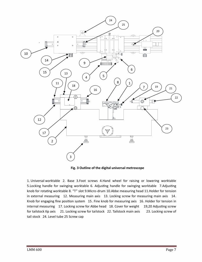
Fig. 3 Outline of the digital universal metroscope
1. Universal worktable 2. Base 3.Foot screws 4.Hand wheel for raising or lowering worktable
5.Locking handle for swinging worktable 6. Adjus�ng handle for swinging worktable 7.Adjus�ng
knob for rota�ng worktable 8. “T” slot 9.Micro-drum 10.Abbe measuring head 11.Holder for tension
in external measuring 12. Measuring main axis 13. Locking screw for measuring main axis 14.
Knob for engaging fine posi�on system 15. Fine knob for measuring axis 16. Holder for tension in
internal measuring 17. Locking screw for Abbe head 18. Cover for weight 19,20 Adjus�ng screw
for tailstock �p axis 21. Locking screw for tailstock 22. Tailstock main axis 23. Locking screw of
tail stock 24. Level tube 25 Screw cap
1
2
3
4 5
6
7
8
9
12
16
11
13
17
14
15
18 19
20
21
22
23
24
10
25
LMM600 Page8
4. Structure :
4.1 Bed
The Bed is used to support the main body of the instrument and all kind of accessories and is
composed of the base 2 and universal worktable 1.
4.1.1 Base (Fig. 3)
The bed is supported by three foot screw 3, which rest in the plates. By means of these
screws and level 24 the bed can be leveled.
4.1.2 Universal worktable (Fig. 3)
The front of the universal worktable is provided a hand wheel for adjus�ng the height. The
worktable can be secured against ver�cal displacement by rotat ing by rota�ng the hand
wheel 4.
The universal worktable 1 is a basic and various accessories can add on it. The worktable 1
also has two “T” slots, which is used to impact the presser. The worktable can do the
following movements for opera�on’s need.
a) The worktable can be ver�cal adjusted within 75 mm by hand wheel 4.
b) The worktable can move within 25 mm in the Y direc�on by turning hand wheel 9. The scale
value of its drum is 0.01 mm.
c) The worktable can �lt ± 3° around the Y axis by adjus�ng opera�on level 6. And can be set to
a defined posi�on using the locking lever 5.
d) The worktable surface can rotate ± 4° around ver�cal axis by turning screw 7.
e) The X direc�on of the worktable moves on the rolling slide. Its travel is 10 mm. thus the test
piece can freely posi�oned without any constraint.
LMM600 Page9
4.2 Abbe measuring head (Fig. 3)
The Abbe measuring head contains the measuring main axis 12 and the gra�ng measuring
system. The gra�ng system operates in the case of transmission with a 100 mm gra�ng scale
as it measuring datum. The re�cle space of the gra�ng scale is 0.02 mm, which has zero
mark as absolute star�ng point for measurement.
The Abbe measuring head can move on the le� side of the bed and be fixed in any posi�on
by locking hand wheel 17
The measuring main axis on the an�fric�on bearings can move in the Abbe head. The locking
screw 13 can lock the measuring main axis in a posi�on. The measuring main axis moves in
the range of 100 mm. the gra�ng reading head is connected with measuring axis and
performs the axis movements along the main axis. The gra�ng scale is fixed on the
unmovable framework.
Screw caps 25 is used to fasten the contact �p connector. Holding the screw cap 25 with
hands can push or pull the main axis. In internal measurement, the end of the cord of the
tension has to be a�ached to holder 16, & in external measurement to holder 11. Inside of
the measuring head rolls are provided by which the cords of the tension are suspended.
Rubber pads prevent a hard impact of the measuring axis at the end of the measuring range.
For a li�le displacement the main axis in the axial direc�on, fine-posi�on knob 15 is used. It
can turn only, if the switching knob 14 upwards. The high transmission ra�o of the fine knob
causes a slow mo�on of the main axis. The circular movement of the hand wheel is
converted into the axial movement of the main axis by fric�ons gears. The fine-posi�on
system is used for measuring holes by means of the electric measuring device. When using
the system, the internal and external tension cords should be come away, and the locking
screw of the main axis should be loosened.
4.3 Tailstock (Fig. 3)
The tailstock main axis serves as a fixed datum (loca�ng surface). Its slide runs on the right
side of the bed and can be locked in any posi�on by knob 23. The tailstock main axis 22 can
be axially displaced in its bushing and locked in any posi�on by locking knob 21. The
measuring lever mounted the contact �p can be arbitrarily adjusted by screw 19 and 20 so
as to make the plane contact �p and measuring surface are parallel to or concentric with
each other.
LMM600 Page10
4.3.1 Adjus�ng the contact �p:
Adjustment of contact �p with plane surface or knife-edge
The purpose is to make the measuring surfaces parallel to each other. Firstly do the coarse
adjus�ng with above the method of finding “turning point” to obtain the minimum value.
Then place the test piece, and observe whether the indica�ng value in different posi�on of
the �ps is the same. Finely adjust the reading difference by screw un�l the reading value in
each posi�on is the same. For measuring the thread pitch diameter with three-pin, place a
three-pin in the up, down, right and le� posi�on of the �p to test the parallelism a�er have
done the coarse adjus�ng. Then be on the fine adjus�ng with purpose.
5. Method of operation:
5.1 Thread Ring Gauge
PITCH DIAMETER.
REQUIRED EQUIPMENT
Master ring gage.
Accessory. : - 1) Internal measurement accessories
Clamp (2nos.).
SETUP.
Clamp internal measurement accessories in anvil of Abbes head. Mode of DRO select Probe
(see Page No. 12 in DRO Manual Point No. 08). Select correct T–Styles for measurement of
thread ring gauge (Refer Page No. 13).
LMM600 Page11
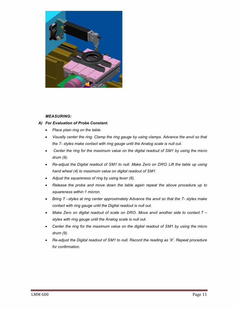
MEASURING:
A) For Evaluation of Probe Constant.
Place plain ring on the table.
Visually center the ring. Clamp the ring gauge by using clamps. Advance the anvil so that
the T- styles make contact with ring gauge until the Analog scale is null out.
Center the ring for the maximum value on the digital readout of SM1 by using the micro
drum (9).
Re-adjust the Digital readout of SM1 to null. Make Zero on DRO. Lift the table up using
hand wheel (4) to maximum value on digital readout of SM1.
Adjust the squareness of ring by using lever (6).
Release the probe and move down the table again repeat the above procedure up to
squareness within 1 micron.
Bring T –styles at ring center approximately Advance the anvil so that the T- styles make
contact with ring gauge until the Digital readout is null out.
Make Zero on digital readout of scale on DRO. Move anvil another side to contact T –
styles with ring gauge until the Analog scale is null out.
Center the ring for the maximum value on the digital readout of SM1 by using the micro
drum (9).
Re-adjust the Digital readout of SM1 to null. Record the reading as ‘X’. Repeat procedure
for confirmation.
LMM600 Page12
Calculations
Probe Constant = X1 – P value
Where,
X1 = Ring actual size - X
Select P value from chart.
(E.g. Ring size = 14.0002, X= 8.7248, P value = 0.404.
X1= 14.0002 – 8.7248
X1= 5.2754
Probe Constant = 5.2754 - 0.404 Probe Constant = 4.8714.)
B) For Evaluation of PITCH DIAMETER of thread ring gauge.
Place thread ring on the table.
Visually center the ring. Clamp the ring gauge by using clamps.
Insert T –styles in second number thread of thread ring gauge.
Center the ring for the maximum value on the digital readout of SM1 by using the
micro drum (9).Re-adjust the Digital readout of SM1 to null.
Re-adjust the Digital readout of SM1 to null. Preset probe constant value by using
preset function of DRO.
Move anvil to contact T –styles in Third number (opposite to first thread) thread of
thread ring gauge.
Center the ring for the maximum value on the digital readout of SM1 by using the
micro drum (9).Re-adjust the Digital readout of SM1 to null.
Move table up to see maximum value on the digital readout of SM1 by using the lifting
hand wheel (4). Re-adjust the Digital readout of SM1 to null.
Record the reading as ‘Pitch Diameter’ of thread ring gauge.
Lift the table to find ‘Pitch Diameter’ at another thread of thread ring gauge.
Calculate variation between ‘Pitch Diameters’ and record as taper of ring gauge.
Rotate thread ring gauges in 90-degree approximately and repeated above
procedure.
Calculate variation between ‘Pitch Diameters’ and record as oval of ring gauge.
LMM600 Page13
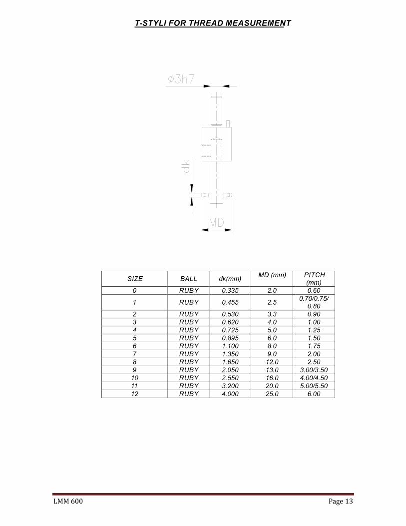
T-STYLI FOR THREAD MEASUREMENT
SIZE BALL dk(mm) MD (mm) PITCH
(mm) 0 RUBY 0.335 2.0 0.60
1 RUBY 0.455 2.5 0.70/0.75/
0.80 2 RUBY 0.530 3.3 0.90 3 RUBY 0.620 4.0 1.00 4 RUBY 0.725 5.0 1.25 5 RUBY 0.895 6.0 1.50 6 RUBY 1.100 8.0 1.75 7 RUBY 1.350 9.0 2.00 8 RUBY 1.650 12.0 2.50 9 RUBY 2.050 13.0 3.00/3.50 10 RUBY 2.550 16.0 4.00/4.50 11 RUBY 3.200 20.0 5.00/5.50 12 RUBY 4.000 25.0 6.00

LMM600 Page14
Chart A: Nominal sizes of cylinders & corresponding “P” values of various thread form.
Nominal Size (d)
Screw Thread for which these Cylinders are suitable
ISO metric Pitches In MM.
Unified & ISO INCH T. P. I.
Whitworth T. P. I. Parallel Threads
B. A. No.
Pitch P
P Value
T. P. I. P Value T. P. I. P Value No. P Value
1 2 3 4 5 6 7 8 9 0.170 0.25 0.047 - - - - 10 0.146
0.30 0.090 - - - - - - 0.195 - - 80 0.080 - - 9 0.154 0.220 0.35 0.083 72 0.086 - - 8 0.162 0.250 0.40 0.096 64 0.094 - - 7 0.175 0.290 0.45 0.100 56 0.103 - - 6 0.172
0.50 0.143 - - - - - - 0.335 0.60 0.185 48 0.123 40 0.219 5 0.174
- - - - - - 4 0.253 0.390 - - 44 0.110 36 0.223 3 0.251
- - 40 0.160 - - - - 0.455 0.70 0.151 36 0.156 32 0.232 2 0.246
0.75 0.195 - - - - 1 0.348 0.80 0.238 - - - - - -
0.530 0.90 0.249 32 0.157 28 0.253 0 0.350 - - 28 0.256 - - - -
0.620 1.00 0.246 26 0.226 26 0.216 0.725 1.25 0.358 24 0.192 22 0.264
- - 22 0.275 20 0.375 - - 20 0.375 19 0.439 - - 19 0.433 - -
0.895 1.50 0.404 18 0.327 18 0.312 - - - - 16 0.482
1.10 1.75 0.416 16 0.275 14 0.460 - - 14 0.471 - - - - 13 0.592 - -
1.35 2.00 0.382 12 0.483 12 0.459 - - 11 0.650 11 0.644
1.65 2.50 0.515 10 0.550 10 0.516 - - 9 0.794 9 0.788
2.05 3.00 0.548 8 0.700 8 0.660 3.50 0.981 7 1.092 7 1.096
2.55 4.00 0.914 6 1.116 6 1.094 4.50 1.347 - - - -
3.20 5.00 1.130 5 1.199 5 1.149 5.50 1.563 4.5 1.688 4.5 1.692
4.00 6.00 1.196 4 1.499 4 1.437 - - - - 3.5 2.308
5.05 - - - - - - 6.35 - - - - - -
Note: - (1) Wires nominal sizes 5.05 mm is used for 9 & 10 mm Trapezoidal pitches & 6.35 is used for 12 mm Trapezoidal pitch. (2) All P value in mm.
LMM600 Page15
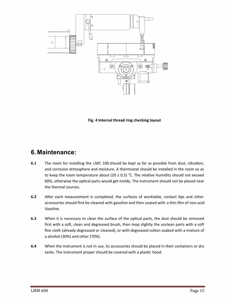
Fig. 4 Internal thread ring checking layout
6. Maintenance:
6.1 The room for installing the LMC 100 should be kept as far as possible from dust, vibra�on,
and corrosive atmosphere and moisture. A thermostat should be installed in the room so as
to keep the room temperature about (20 ± 0.5) °C. The rela�ve humidity should not exceed
60%, otherwise the op�cal parts would get moldy. The instrument should not be placed near
the thermal sources.
6.2 A�er each measurement is completed, the surfaces of worktable, contact �ps and other
accessories should first be cleaned with gasoline and then coated with a thin film of non-acid
Vaseline.
6.3 When it is necessary to clean the surface of the op�cal parts, the dust should be removed
first with a so�, clean and degreased brush, then mop slightly the unclean parts with a so�
fine cloth (already degreased or cleaned), or with degreased co�on soaked with a mixture of
a alcohol (30%) and other (70%).
6.4 When the instrument is not in use, its accessories should be placed in their containers or dry
tanks. The instrument proper should be covered with a plas�c hood.