Embed Size (px)
Citation preview
NAVAL FACILITIES ENGINEERING SERVICE CENTER Port Hueneme, California 93043-4370
Technical Report TR-2087-ENV
OPERATIONAL TEST REPORT FOR FIELD DEMONSTRATION TESTING OF THE
MOBILE ALKALINE CLEANER RECYCLER
by
Aviva Speceal
May 1998
^CQTJOT^^1
Approved for public release; distribution is unlimited.
v\ Printed on recycled paper
REPORT DOCUMENTATION PAGE FormApproved OMB No. 0704-018
Public reporting burden for this collection of information is estimated to average 1 hour per response, including the time for reviewing instructions, searching existing data sources, gathering and maintaining the data needed, and completing and reviewing the collection of information. Send comments regarding this burden estimate or any other aspect of this collection information, including suggestions for reducing this burden, to Washington Headquarters Services, Directorate for Information and Reports, 1215 Jefferson Davis Highway, Suite 1204, Arlington, VA 22202-4302, and to the Office of Management and Budget, Paperwork Reduction Project (0704-0188), Washington, DC 20503.
1. AGENCY USE ONLY (Leave blank) 2. REPORT DATE
May 1998 3. REPORT TYPE AND DATES COVERED
Interim
4. TITLE AND SUBTITLE OPERATIONAL TEST REPORT FOR FIELD DEMONSTRATION TESTING OF THE MOBILE ALKALINE CLEANER RECYCLER
5. FUNDING NUMBERS
6. AUTHOR(S)
AvivaSpeceal
7. PERFORMING ORGANIZATION NAME(S) AND ADDRESSE(S) Naval Facilities Engineering Service Center 1100 23rd Avenue Port Hueneme, CA 93043-4370
8. PERFORMING ORGANIZATION REPORT NUMBER
TR-2087-ENV
9. SPONSORING/MONITORING AGENCY NAME(S) AND ADDRESSES
Chief ofNaval Operations Environmental Protection, Safety, and Occupational Health Division (N45) 2000 Navy Pentagon Washington, DC 20350-2000
10. SPONSORING/MONITORING AGENCY REPORT NUMBER
11. SUPPLEMENTARY NOTES
Program managed by Naval Facilities Engineering Command, Washington, DC
12a. DISTRIBUTION/AVAILABILITY STATEMENT
Approved for public release; distribution is unlimited. 12b. DISTRIBUTION CODE
A
13. ABSTRACT (Maximum 200 words)
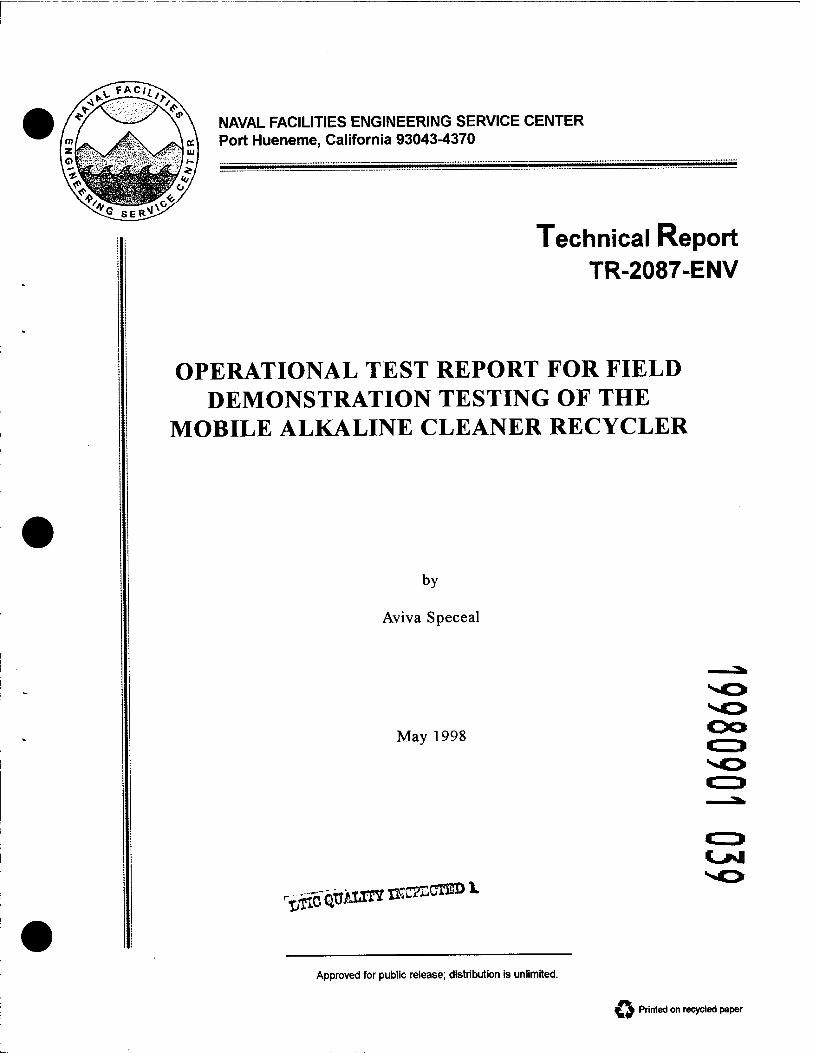
An automated crossflow filtration process using a ceramic membrane was evaluated for recycling spent alkaline cleaners generated from closed cabinet aqueous parts washers. Two field tests conducted at Naval Air Weapons Station Point Mugu, California, and the Naval Facilities Engineering Service Center, Port Hueneme, California, demonstrated an 80% removal of accumulated oil and grease from spent cleaners after recycling. The Mobile Alkaline Cleaner Recycler also demon- strated an 88% volumetric reduction of hazardous waste. The economics of the process is dependent on the generation of spent alkaline cleaner, local hazardous waste disposal costs, and alkaline cleaner replacement costs.
14. SUBJECT TERMS
Crossflow filtration, recycle alkaline cleaners, closed cabinet aqueous parts washers.
15. NUMBER OF PAGES 57
16. PRICE CODE
17. SECURITY CLASSIFICATION OFREPORT
Unclassified
18. SECURITY CLASSIFICATION OF THIS PAGE
Unclassified
19. SECURITY CLASSIFICATION OF ABSTRACT
Unclassified
20. LIMITATION OF ABSTRACT
UL
NSN 7540-O1-280-5500 Standard Form 298 (Rev. 2-89) Prescribed by ANSI Std. 239-18
EXECUTIVE SUMMARY
Since the phase out of ozone depleting substances, the cleaning industry has switched to aqueous based alkaline cleaners for degreasing of metal parts. These alkaline cleaners are typically used in immersion baths and in closed cabinet aqueous parts washers. Once these aqueous cleaners have reached their emulsifying capacity they are disposed of as hazardous waste. It is estimated that the Navy currently uses 350 of these closed cabinet washers which generate approximately 580,000 pounds per year of spent alkaline cleaners. The generation of this waste stream is projected to increase as additional washers are received through the Navy's Pollution Prevention Procurement Program and as additional solvent cleaners are phased out and replaced with aqueous based alkaline cleaners. Naval Facilities Engineering Services Center (NFESC) was tasked with developing a mobile system for recycling spent alkaline cleaners from closed cabinet aqueous parts washers. NFESC developed the Mobile Alkaline Cleaner Recycler (MACR), an automated user-friendly recycling system, which utilizes a ceramic crossflow ultrafiltration membrane. This report summarizes the results from field demonstration tests conducted on the MACR.
The crossflow filtration is a pressure driven process. The technology is based upon turbulent flow through a cylinder made from porous material. The turbulent flow has a scouring effect on the membrane surface which reduces membrane fouling. Most of the flow travels a tangential path to the membrane surface, however, a small portion of flow travels from the inside membrane channel to the outside surface of the porous cylindrical membrane where it is collected for reuse. This is the purified stream known as the permeate. The major portion of flow which is rejected by the membrane exits via the tangential path. This portion is known as the retentate.
The two field demonstration tests were conducted at Naval Air Weapons Station, Pt. Mugu and at Naval Facilities Engineering Service Center, Port Hueneme using solution collected from Construction Equipment Department, CBC, Port Huemene. The main objectives of the test addressed the ability of the recycling system to remove oil and grease from spent alkaline cleaners, the effectiveness of the self-cleaning regime for membrane maintenance, membrane fouling tendencies, and process time.
Prior to field demonstration testing, the permeate flowrate of deionized water through the unused membrane filter was benched-marked at 2.3 gpm at 145 °F. After completing field testing, the final permeate flowrate of deionized water was measured was 2.5 gpm at 145 °F. The comparison of these two values indicated that no membrane fouling had occurred and the self-cleaning process effectively maintained the membrane's permeability.

A total of seven test runs were conducted which recycled nearly 1,000 gallons of spent alkaline cleaner. Each test run purified up to 140 gallons of spent cleaner is less than 6 hours. A total of 26 samples were collected from the feed, the permeate, and the retentate streams. Samples were analyzed for pH and oil and grease concentrations. The pH values of the samples taken were virtually unchanged indicating: 1) that the membrane had no effect on the pH of the test solutions, 2) the amounts of oils and greases removed from the purified solution had no noticeable effect on the pH of the cleaner. In the first field demonstration test the oil and grease concentrations for the feed, permeate, and retentate streams averaged 537.5 mg/L, 115 mg/L, and 11,750 mg/L respectively. The percent decrease of oil and grease in the purified permeate stream averaged 79%. In the second field demonstration test the oil and grease concentrations for the feed, permeate, and retentate streams averaged 3,950 mg/L, 848.5 mg/L, and 26,000 mg/L respectively. The percent decrease of oil and grease in the purified permeate stream averaged 83%.
The MACR demonstrated an 88 % volumetric reduction of hazardous waste. This volumetric reduction includes disposal of the membrane cleaner solution, a nonfoaming detergent, after the seventh use. The capability of reusing the membrane cleaner solution may vary depending upon the severity of contaminants in the spent cleaner. Currently the system is designed to process 140 gallons of spent cleaner yielding 12 gallons of concentrated hazardous waste and 128 gallons of reusable cleaner. With slight modifications to the system, process volumes can be increased to accommodate larger parts washer sumps.
The economics of the process are dependent on the generation of spent alkaline cleaner, local hazardous waste disposal costs, and alkaline cleaner replacement costs. For example, an activity with seven 140 gallon parts washers, a hazardous waste disposal rate of $1.00 per pound, alkaline cleaner costs of $ 1.68 per pound of solution, and a quarterly changeout of solution will experience annual operating costs of $39,278. With recycling, the projected operating costs are estimated at $11,462 resulting in an annual savings of $27,816. Payback period is estimated to be 15 months. This estimation is based upon a sixfold extension of cleaner life and assumes equivalent labor costs.

ACKNOWLEDGEMENT
This work was funded by the Pollution Abatement Ashore Program, managed by Naval Facilities Engineering Command and sponsored by the Environmental Protection, Safety and Occupational Health Division (N45) of the Chief of Naval Operations. The information contained in this report will be used to procure and operate a mobile alkaline cleaner recycler.
in
TABLE OF CONTENTS Page
1.0 INTRODUCTION 1
2.0 BACKGROUND 1
3.0 OBJECTIVES 2
4.0 SYSTEM DESCRIPTION 2 4.1 Control Logic Description 4
4.1.1 Transfer Mode 4 4.1.2 Recycle Mode 4 4.1.3 Membrane Cleaning Mode 4 4.1.4 Rinse Mode 4 4.1.5 Return Mode 5
4.2 Valve Positions 7 4.3 Safety Switches and Tracking Devices 8
5.0 FIELD TEST DEMONSTRATION PROGRAM 8 5.1 Approach 8 5.2 Clean Water Permeability 8 5.3 Analytical Procedures 9 5.4 Monitoring 9 5.5 Standard Operating Procedures 11 5.6 Sampling Procedures 11
6.0 FIELD DEMONSTRATION TESTS 12
7.0 SYSTEM MODIFICATIONS 13 7.1 Modifications After First Field Demonstration Testing 13 7.2 Modifications After Second Field Demonstration Testing 13
8.0 FIELD DEMONSTRATION TEST RESULTS 13 8.1 Clean Water Permeability 13 8.2 Flowrate and Pressure Readings 15 8.3 Temperature Readings 16 8.4 Analytical Test Results 18
8.4.1 pH 18 8.4.2 Oil and Grease 19 8.4.3 Membrane Cleaner Solution 22
IV

TABLE OF CONTENTS (Continued)
Page
9.0 FURTHER CONSIDERATIONS 23 9.1 Volumetric Reduction of Hazardous Waste 23 9.2 Membrane Storage 23
10.0 CONCLUSIONS AND RECOMMENDATIONS 24
11.0 REFERENCES 26
APPENDIX A: MASS BALANCE CALCULATIONS A-l
APPENDIX B: MATERIAL SAFETY DATA SHEETS FOR FIELD TESTING OF THE MOBILE ALKALINE CLEANER RECYCLER B-l

LIST OF TABLES Page
Table 1: Ceramic Membrane Module Specifications 3 Table 2: Valve Positions During Operating Modes 7 Table 3: Clean Water Flow Rates and Permeability 14 Table 4: Flowrate, Volumetric, and Pressure Readings 15 Table 5: Temperature Readings of the Membrane Cleaner Solution 16 Table 6: pH Results For First Field Demonstration Test 18 Table 7: Laboratory Analysis of Oil and Grease For The
First Field Demonstration Test 19 Table 8: Laboratory Analysis of Oil and Grease For The
Second Field Demonstration Test 19 Table 9: Oil and Grease Removal 21 Table 10: Mass Balance Analysis of Oil And Grease For
The Second Field Test 22 Table 11: Laboratory Analysis of Oil And Grease In
The Used Membrane Cleaner Solution 23
VI

LIST OF FIGURES Page
Figure 1: Process Flow Diagram 6 Figure 2: Gauge, Flow Meter, and Sampling Locations 10 Figure 3: Temperature Rise of Membrane Cleaning Solution, Run 5 18 Figure 4: Temperature Rise of Membrane Cleaning Solution, Run 6 18 Figure 5: Temperature Rise of Membrane Cleaning Solution, Run 7 19
Vll
1.0 INTRODUCTION
The Navy, like many industrial operators, is under increased regulatory, public and monetary pressures to reduce the quantities of hazardous waste that it generates each year. Executive Order 12856 mandates a 50% weight reduction by 2000 in the amount of hazardous waste produced, using 1992 as the base year, and to meet the Environmental Protection Agency (EPA) regulations. To this end, the Chief of Naval Operations (CNO) has called for a hazardous waste minimization program to put both procedures and the necessary equipment into place that would reduce the quantity of hazardous waste now treated and/or disposed of off-site under a contract or disposed of on-site at the installation.
2.0 BACKGROUND
Cleaning of metal surfaces in an aqueous alkaline solution to remove oil and grease from parts prior to finishing, coating, repair, or maintenance operations is a practice inherent to all DoD facilities that conduct depot or intermediate level maintenance. When an alkaline cleaner is used, contaminants in the form of emulsified oil and grease, and suspended solids comprised of metals, and carbonaceous particles accumulate in the solution. Over time, the levels of contaminants build to a point where they interfere with the surface cleaning reactions, and also exceed the capacity of the cleaning solution to emulsify additional oil. At this point the cleaner is rendered ineffective, and the solution is discarded, and replaced with fresh chemicals. After use, alkaline cleaning solutions, even if initially environmentally benign, are disposed off-site or treated on-site as hazardous wastes, due to the presence of chemically stabilized oil/water emulsions, and possibly Federally or state regulated heavy metals.
Spent alkaline cleaning solutions can be recycled by physically separating the suspended solids, emulsified oil, and grease from solution, while leaving the constituents of the cleaner-formulation intact. Crossflow filtration (CFF) is considered ideal for this application. CFF is a pressure driven process in which the feed stream flows in a path tangential to the filter or membrane surface. The advantage of this technology over barrier filtration is that the scouring action created by the turbulent flow through the membrane structure reduces fouling. Membrane pore sizes in the micro (0.1 to 5 microns) to ultrafiltration (0.005 - 0.1 to microns) range are required.
With the phase out of cleaning methods based on ozone depleting substances (ODS), the Navy has been purchasing cabinet-type parts-washers that utilize non-ODS aqueous solutions, typically alkaline cleaners, as substitutes. Driven by pollution prevention mandates, NAVFAC tasked Naval Facilities Engineering Service Center (NFESC) to develop a cost effective, user-friendly recycling system to extend the life of spent alkaline cleaners generated from closed cabinet aqueous parts washers. After testing various membranes, NFESC developed an automated recycling system utilizing crossflow technology with a ceramic membrane. The mobile system is designed to service multiple parts washers located throughout an activity.
3.0 OBJECTIVES
The objectives of the field demonstration test program were as follows:
• Determine the ability of the recycling system to remove oil and grease from a spent alkaline cleaner and from accumulated spent membrane cleaning solution.
• Determine membrane fouling tendencies (by conducting clean water permeability test before, between, and after recycling test runs and by monitoring permeate flowrates during recycle runs).
• Determine and evaluate the most effective membrane cleaning process (i.e. duration of membrane self-cleaning process, membrane cleaner solution, temperature, flow configuration).
• Determine the number of times the membrane cleaning solution can be reused before being rendered inadequate.
• Determine operation, maintenance, and life cycle costs.
4.0 SYSTEM DESCRIPTION
The Mobile Alkaline Cleaner Recycler (MACR) is a skid-mounted system with dimensions 8x5x6 feet. Basic system components consist of four tanks, a ceramic membrane manufactured by U.S. Filter, and three pumps supplied by Pump Engineering Company. The four tanks include a 55 gallon concentration or working tank, a 180 gallon permeate tank, a 37 gallon membrane cleaner tank, and a 37 gallon rinse tank. Two of the pumps are 1/2 horsepower close-coupled, positive-displacement, screw-type, progressive-cavity pumps used to transfer the feed and the purified solution. The third pump is a 7.5 horsepower close-coupled, centrifugal pump used to recirculate solution through the system. Piping and fittings are constructed from chlorinated Polyvinylchloride (CPVC), polypropylene, or 316 stainless steel. The membrane specifications are presented in Table 1. The fully automated system requires no further operator assistance after hookup and includes a built-in membrane cleaning cycle. The system requires 240 volts and 3 phase power to operate the transfer pumps, the recirculation pump, and the actuated valves.

Table 1: Ceramic Membrane Module Specifications Parameter Specification
Service Type Gasket Material Membrane Area
Light Industrial Ethylene Propylene Rubber (EDPM) 18 Square Feet
Channel Opening Diameter 4 Millimeters Element Length Number of Elements
1020 Millimeters 7
Channels Per Element 19 Nominal Pore Diameter 0.05 Microns Support Layer Material Filter Surface
a-alumina Zircona
Fluid Temperature Range Feed Solution pH
60-200 °F 8-14
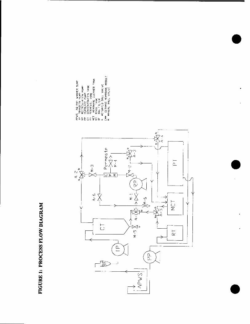
After inserting inlet and outlet transfer hoses into the parts washer sump and activating the 'Start" button, contaminated bath solution is automatically transferred by pump from the aqueous parts washer sump, through a bag filter, and into the concentration tank. The contaminated solution is recirculated from the concentration tank through the membrane element and back to the concentration tank. At the membrane surface, contaminates in the form of oil and grease emulsions are rejected and exit the membrane longitudinally. This stream, which is referred to as the retentate, is returned to the concentration tank. The aqueous cleaning solution, which passes through the membrane, is purified for reuse and exits the membrane laterally. This stream, which is referred to as the permeate, is collected in the permeate tank. A series of liquid level switches in the concentration tank regulate the transfer of solution to prevent overfilling and to supply new spent solution as the permeate exits the recirculation loop. When all the solution in the parts washer sump has been transferred, the liquid level in the concentration tank draws down, thus concentrating the retentate, to a predetermined volume of 11.75 gallons. After draw- down, the unit switches over to the membrane cleaning mode. The membrane cleaning solution, a non-foaming detergent, is circulated through the membrane for 1 to 2 hours with the permeate line redirected back to the membrane cleaner tank. After the cleaning cycle is completed, rinse water is circulated through the system with the permeate line directed into the permeate tank. The rinse water volume which is directed to the permeate tank is equal to the volume of the retentate. When the rinse cycle is completed, the purified solution in the permeate tank is returned from to the parts washer sump. Prior to the next use, the concentrated retentate is manually drained from the bottom of the concentration tank and containerized for hazardous waste (HW) disposal. The water tank is then refilled to the fill line. The membrane cleaning solution is reused until it becomes ineffective. The MACR process flow is illustrated in Figure 1.

4.1 Control Logic Description
After connecting power to the unit, inserting the cleaner transfer hose and permeate return hose into the bottom of the aqueous parts washer sump, and starting the unit, the system transitions through five modes of operation as detailed below.
4.1.1 Transfer Mode
The Transfer Pump (TP) runs until the liquid level in the Concentration Tank (CT) reaches Liquid Level Switch 1 (LLS-1). The TP then runs intermittently based on inputs from LLS-1 and LLS-2 during the recycle mode. LLS-1 will cause the TP to turn off and LLS-2 will cause the TP to turn on. All actuated valves A-l through A-5 are in the "a" position. Actuated valve A-6 is in the closed position.
4.1.2 Recycle Mode
Recirculating Pump (RP) starts running when the liquid level in the CT first reaches LLS- 2. After the RP begins running, valve A-6 opens. When no flow is detected by the No Flow Switch (NFS) located on the discharge side of the TP, the TP pump turns off and remains off. Once this occurs, the liquid level in the CT draws down until the liquid level reaches LLS-3 causing the RP to turn off, thus terminating the recycle mode.
4.1.3 Membrane Cleaning Mode
Once RP turns off, a timer is activated for the membrane cleaning mode. Valves A-l, A- 2, and A-3 move into the "b" position and A-6 closes. Valves A-4 and A-5 are in the "a" position. The RP begins running after which valve A-6 opens. The membrane is cleaned by circulating a hot, non-foaming detergent solution through the membrane with both the permeate and retentate directed back to the membrane cleaner tank (MCT). The RP will heat the detergent solution approximately one degree °F per minute. When the preset value of the timer is reached, or when the solution in the MCT reaches 180 °F the Membrane Cleaning Mode is automatically terminated.
4.1.4 Rinse Mode
When the Membrane Cleaning Mode is terminated, the RP turns off. Valve A-6 closes, valve A-3 moves into the "a" position, and valves A-4 and A-5 move into the "b" position. The RP begins running after which valve A-6 opens and rinse water is circulated through the membrane with the permeate directed back into the permeate tank and the retentate directed back into the rinse tank (RT). The water level in the RT draws down to LLS-4 causing the RP to turn off and remain off, thus terminating the Rinse Mode.

4.1.5 Return Mode
After the RP turns off, valve A-6 closes and the permeate pump (PP) turns on. The permeate accumulated in the Permeate Tank (PT) is returned to the aqueous parts washer sump (APWS). When the liquid level in the permeate tank draws down and activates LLS-5, valves A-l, A-2, A-4, and A-5 return to the "a" position. Once the NFS, located on the discharge side of the PP, detects no flow, the PP turns off and the cycle is completed.
?II I -
-* n
<* <r u or
CjVU £< £>
> daaa < i- or a
u i 3: £
ua or a i
ua i QTE < CJS:
s
O J
W Ü
§ Ok

4.2 Valve Positions
The automated and manual valve positions for the operating modes are presented i Table 2.
in
Table 2; Valve Positions During Operating Modes Valve
A-l A-2 A-3 A-4 A-5 A-6
M-l M-23
M-3 M-43
M-54
M-64
Transfer
"a"
"a" "a"
Closed
Open Open Open Open
Closed Closed
Recycle
"a"
"a" "a"
Closed / Open2
Open Open Open Open
Closed Closed
Membrane Cleaning
"b" "b" «V"
'b' 'br
'br
"a" "a"
Closed / Open2
Open Open Open Open
Closed Closed
Rinse
"b" Mr" 'b' "a"
"b" Closed / Open2
Open Open Open Open
Closed Closed
Return
"a"' "a"' "a" "a"' "a"'
Closed
Open Open Open Open
Closed Closed
Valves change near end of cycle. Opens after RP Starts. Closes after RP stops. Closed during storage. Opened for periodic cleaning and draining the lines.
4.3 Safety Switches And Tracking Devices
• If LLS-1 malfunctions, LLS-6 will act as a High-High switch and will shut off the TP to prevent the concentration tank from overflowing.
• If the temperature probe in the MCT senses that the detergent solution exceeds 180 °F (due to the addition of pump energy into the system), the Membrane Cleaning Mode will terminate and the Rinse Mode will begin.
• LLS-7 will act as a High High switch and will shut off the TP to prevent the permeate tank from overflowing.
• If no flow is detected in either of the No Flow Switches (NFS) located on the discharge side of the TP and PP, the TP or PP will turn off.
• The Turbine Flow Meter with Totalizer (TFM) tracks the amount of permeate generated for record keeping purposes.
5.0 FIELD DEMONSTRATION TEST PROGRAM
5.1 Approach
The test program consisted of a total of seven performance runs processing two different spent alkaline cleaners, Ultraclean SP and Hotze Tubmate. Performance runs #1 through #4 were conducted during the first field demonstration test at Naval Air Weapons Station Pt. Mugu, CA and performance runs #5 through #7 were conducted during the second field demonstration test at NFESC, Port Hueneme, CA. Each performance run recycled up to 140 gallons of spent alkaline cleaner collected from one to four different closed cabinet aqueous parts washers. The performance of the MACR was measured by standard methods of chemical analysis, by clean water permeability (CWP) tests, and by monitoring the permeate flowrate during the performance runs.
5.2 Clean Water Permeability
Prior to field demonstration testing, the performance of the unused membrane filter was benched-marked according to the permeability of the membrane to deionized water at 140 °F. The value obtained, known as clean water permeability (CWP), is defined as the volume of permeate processed through the membrane per unit area of membrane surface per time (measured in L/m2-hr). The CWP is used to determine any decrease in membrane performance that is an indication of membrane fouling. Subsequent CWP tests were conducted after each of the four performance runs in the first field test and prior to run #5 and following run #7 in the second field test. Values obtained were compared with the bench-mark value.

5.3 Analytical Procedures
The samples collected during the first field demonstration test were analyzed for pH and oil and grease. The samples collected from the second field demonstration test were analyzed for oil and grease. Oil and grease and pH samples were analyzed by a local contracted laboratory using EPA Method 413.1 and EPA Method 150.1 respectively. Analysis was not performed for alkalinity, or surfactant losses for the following reasons:
• Tests results from a joint Naval Facilities Engineering Service Center (NFESC) and EPA Strategic Environmental Research and Development Program (SERDP) project conducted at Naval Aviation Depot (NADEP) North Island demonstrated that the pH and alkalinity of alkaline cleaner solutions are not affected by the presence of oil and grease nor are they affected by the CFF filtration process (Chen, Drescher, Pollack, and Wang).
• The permeate is not expected to contain surfactants (Chen, Drescher, Sass, Giammar, Hutson, and Pollack). The EPA SERDP study determined that surfactants which are bound to the oil and grease in the form of an emulsion, are basically removed from the cleaner during the filtration process.
5.4 Monitoring
The pressure gauges located on the transfer pump discharge side and the inlet and outlet sides of the membrane and vacuum gauges on the inlet and outlet side of the bag filter were monitored. Increased readings on the outlet vacuum gauge could indicate a clogging bag filter. Increased pressure readings on the membrane outlet could indicate possible membrane fouling or obstructions in the piping. A turbine flow meter on the permeate line tracked permeate flowrates and totalized the volume of permeate processed. Start and stop times and gallons processed were recorded. Figure 2 shows sampling and gauge locations.

D "> 0.
<* I UJ Q_
^ D- 1-
< <r u C* UJ
o. a. 0. < >- a;
Q. 7 V UJ s: c z _J 3 — <i u a. i- >- v iy
< yzu UJ o? u z < ;r 1— *— t— C i— 1 <z<ror — uj uj uj en _j u. x o s s: Xr. UD u I -« a u a. am
D.U0.XKE
D
> or
0y UJ £ i- <r < a- 3 UJ >- u o «
s:
<r u>
UJ UJ ,
> □
BCZ or —
_J UJ m
< a. c^r 3 s: 3
co u s: a i-
2
□
Of
■c a UJ 34> _j or < ■=/ u UJ o j?
UJ ui <r UJ ^ z i-: > a .
3
z < <r UJ 0^ UJ u o CT. x ;
DuJUu-0^5 u u x a ty u >
u u. i a or a f I/O oo ^ ^, o^ a. >

5.5 Standard Operating Procedures
For each test run the following steps were taken: 1) 120 to 140 gallons of spent alkaline cleaner were pumped into a 200 gallon tank used to simulate the sump of an aqueous parts washer, 2) Deionized water was added to the rinse tank to the fill line, 3) Valves were checked for correct starting positions, 4) Prerun samples were taken, 5) After connecting to the utility hookup, the start button was activated, 6) As the system transferred solution, the unit was checked for leaks, pressure and vacuum gauges were monitored and recorded, and alkaline cleaner permeate and rinse water permeate samples taken, 7) As the recycling process progressed, additional permeate samples and retentate samples were collected and system operating conditions were monitored and recorded. Operating conditions included permeate flowrates, volumes of permeate processed, and temperature rises of the membrane cleaning solution. In the first field demonstration test, a CWP determination followed each test run. In the second field demonstration test, CWP tests were only performed before the fifth and after the final run. After the completion of each field demonstration test, all hazardous wastes were containerized, labeled, and disposed through proper channels.
5.6 Sampling Procedures
In the first field demonstration test, single samples were taken prior to the test runs, during the test runs, and after the test runs. The prerun sample set consisted of samples of alkaline cleaner from the feed stream, rinse water, and the membrane cleaner solution. Samples of the alkaline cleaner permeate and rinse water permeate were collected during the recycling mode. Postrun samples were taken of the rinse water, the membrane cleaner solution, and the retentate.
In the second field demonstration test, samples of alkaline cleaner were collected from the feed prior to testing and when approximately half of the feed had been processed. Multiple permeate samples were collected at the beginning, middle, and near the end of the recycling mode. Multiple retentate samples were also collected after the recycling mode terminated. A fifth and last test run was conducted using the spent membrane cleaner solution accumulated from the first and second field demonstration tests. Multiple samples were taken of the feed, the permeate, and the retentate.
Each 1 liter sample was collected in specially cleaned glass jars with Teflon lined lids and marked labels. The samples were collected and labeled by NFESC personnel and sent off-site to a contracted laboratory where they were analyzed.
During the first field test, sampling the feed, retentate, and membrane cleaner streams was accomplished by filling the collection jar via a sampling port located near the bottom of the respective tank. Sampling of the permeate was accomplished by filling the collection jar directly from the permeate effluent line. Sampling the water stream was accomplished by dipping the collection container into the middle of the rinse tank. During the second field test, sampling the feed was accomplished by dipping the sample
11

container into the middle of the feed tank while an aerator mixed the feed solution. The contents of the concentration tank were drained into a separate tank, measured, and sampled by dipping the sample container into the middle of the tank but without the aid of an aerator. Sampling of the permeate was accomplished by filling the sample container directly from the permeate effluent line. Sampling locations are shown in Figure 2.
6.0 FIELD DEMONSTRATION TESTS
The first field demonstration test was conducted at Naval Air Weapons Station Pt. Mugu, CA from 29 April to 12 May 1997. Four test runs were conducted using spent alkaline cleaner from one closed cabinet aqueous parts washer located in the Ground Support Equipment shop. The spent alkaline cleaner, Ultraclean SP, had been used in a Roto-Jet parts washer for one year. Four CWP tests were also performed after each of the four test runs to determine the degree of membrane fouling. A total of 28 samples were collected and analyzed for pH and oil and grease.
The first performance test run proceeded with a few minor interruptions due to a faulty circuit breaker at the utility connection. During the second run, however, the membrane showed evidence of severe fouling. Testing was halted and the membrane cleaning process re-examined. A solution of Cascade LiquiGel, a non-foaming dishwashing detergent, proved to be an effective cleaner. Testing resumed without further fouling incidents.
The second field demonstration test was conducted at NFESC, Port Hueneme, CA from 16 June to 15 August 1997. The testing consisted of four runs. Runs #5 through #7 processed spent alkaline cleaner collected from four different Better Engineering aqueous parts washers located at Construction Equipment Department (CED), CBC Port Hueneme. The collected alkaline cleaner, Hotzy Tubmate, was used to clean diesel engines and other automotive parts for vehicle maintenance. Shop personnel reported that over one year had passed since each of the parts washer solutions had been changed. The solution in one parts washer was reported to have in use for two years. The eighth and final run processed the used Cascade LiquiGel solution (accumulated from previous membrane cleanings) to determine the membranes capability to remove oil and grease from this waste stream. A total of 23 samples were collected and analyzed for and oil and grease.
12
7.0 SYSTEM MODIFICATIONS
7.1 Modifications After First Field Demonstration Testing
During the first field demonstration test, one of the automated controls presented an operational problem. The recirculation pump was programmed to run an additional minute after the liquid level in the concentration tank had drawn past the lowest liquid level switch (LLS-3). In the lowered position, the switch, would activate the system to begin the Membrane Cleaning Mode. Setting the recirculation pump to run an extra minute allowed the switch to remain in the lowered position when residual membrane drainage raised the liquid level. However, due to greater solution viscosities, some spent alkaline cleaners required the recirculation pump to run longer than one minute to prevent residual membrane drainage from raising the lowest liquid level switch. After the first field demonstration test, this problem was corrected by rewiring the electrical circuitry to accommodate variations in solution viscosity.
On the permeate line, between the membrane and the permeate tank, a two way actuated ball valve was replaced with a three way actuated ball valve. Instead of merely scouring the inner membrane wall, this new configuration allows the membrane cleaning solution to also pass through the membrane pores as permeate. The membrane cleaning solution permeate is then directed back to the membrane cleaner tank via the three way valve.
7.2 Modifications After Second Field Demonstration Testing
The modifications to the system after the second field demonstration test eliminated an immersion heater used for heating the membrane cleaning solution. A temperature safety feature was installed. When the temperature probe in the MCT senses the detergent solution exceeding 180 CF (due to the addition of pump energy into the system), the Membrane Cleaning Mode terminates and the Rinse Mode automatically begins. A system bypass button and switch were also installed to allow recirculation of harsh chemicals through the system without passing through each automated mode.
8.0 FIELD DEMONSTRATION TEST RESULTS
8.1 Clean Water Permeability
The performance of the unused membrane filter was established by an initial clean water permeability (CWP) test. CWP tests were also conducted after various test runs. Any decrease in permeability from the benchmarked CWP would indicate membrane fouling. CWP testing consisted of circulating deionized water (heated to approximately 175 °F) through the system. When the permeate temperature fell to 140 °F the permeate flowrate was recorded. Results of the initial benchmark test and subsequent CWP tests are shown in Table 3.
13

Table 3: Clean Water Flow Rates and Permeability Run Number Date Location Permeate Permeate Flux*
Flowrate Temperature (L/(m2 x (gpm) <°F) hr))
Benchmark 4-25-97 NFESC, Port Hueneme
2.3 145 31.24
1 4-29-97 NAWS, Pt Mugu 1.5 100 20.37 2 4-30-97 NAWS, Pt Mugu 0.2 132 2.72 3 5-9-97 NAWS, Pt Mugu 1.8 140 24.45 4 5-12-97 NAWS, Pt Mugu 1.5 140 20.37 5** 6-4-97 NFESC,
Port Hueneme 2.2 135 29.88
7 8-13-97 NFESC, Port Hueneme
2.5 143 33.95
Flux is defined as the volume of permeate produced per square meter of membrane surface area per hour.
** CWP test performed prior to Run #5.
Clean Water Permeability tests were performed after each of the four runs in the first field demonstration test. It was felt that the added treatment of hot water running through the system after each test run might contribute an additional cleaning to the membrane and could possibly skew permeability flowrates for the following test run. Therefore, before conducting the second field demonstration test it was decided to perform a CWP test before the fifth run and after the last run in order to better determine the effect of membrane fouling during typical use in the field.
The permeability of the new ceramic membrane was benchmarked at 2.3 gpm at 145 °F. The subsequent tests in the first field demonstration series showed a steady decrease in the membrane's permeability. Although the permeability flowrate of 0.2 gpm in Run #2, indicated a fouled membrane, fouling was reversed as seen in Run #3 where the permeability flowrate was 1.8 gpm at 140 °F. The permeability flowrate of 1.5 gpm at 140 °F in the fourth (last permeability test of the Mugu field demonstration test) showed a 35% decrease from the benchmarked permeability.
The efficiency of the cleaning process in the NFESC field test increased after the system was reconfigured (from that used at Mugu) to allow the membrane cleaning solution to permeate through the membrane pores instead of just scouring the surface of the inner membrane wall. This increased cleaning efficiency is seen in the higher permeate flowrates of runs #5 through #7 which processed a spent cleaner heavily loaded with particulates and eight times more oil and grease than that found in the spent cleaner processed in the Mugu field demonstration test runs. After the seventh run, a total of approximately 950 gallons of spent solution was processed through the system and the final CWP, 2.5 gpm at 143 °F, was undiminished from the benchmarked permeability, 2.3 gpm at 145 °F.
14

8.2 Flowrate and Pressure Readings
Figure 2 shows the locations of the flow meter and pressure gauges on the system. Table 4 shows the flowrate and pressure readings recorded during the two field demonstration tests.
Table 4: Flowrate, Volumetric, and Pressure Readings Run Permeate Permeate Membrane Membrane Transfer Pump
Flowrate Accumulated Pressure Inlet
Pressure Outlet
Pressure
(gpm) (gal) (psi) (psi) (psi) 1 0.9 58 28 9 10
0.8 83 28 9 - 1.0 106 28 9 -
2 (Trickle) - 30 8 10 0.4 - 30 8 -
3 1.3 42 28 8 10 4 1.3 65 28 8 10 5 1.1 24 36 0 10
0.9 45 36 0 - 0.9 62 36 0 - 0.8 73 36 0 -
6 1.3 20 35 0 10 1.3 60 35 0 - 1.4 85 35 0 -
7 1.3 19 35 0 10 1.4 60 35 0 - 1.3 85 35 0 -
In the first field demonstration, permeate flowrates ranged between 0.9 and 1.3 gpm and averaged 1.1 gpm. This excludes the extremely low flowrates from run #2 which indicated a fouled membrane. Permeate flowrates in the second field demonstration test ranged from 0.9 to 1.4 gpm and averaged 1.2 gpm. Though ranges and averages for the two demonstration tests appear similar, the system in the second field test was challenged with a solution notably higher in solids and with an oil and grease concentration 8 times greater than that processed in the first field demonstration test. The effects of this highly contaminated solution are clearly indicated in the initial run of the series, run #5, which showed a steady decline in permeate flowrates from 1.1 to 0.8 gpm. During this particular run the bag filter clogged twice during solution transfer. Transfer was prematurely halted to prevent a third clogging when a fine sludge was noticed settling in the bottom of the feed tank. Apparently enough particulates were screened out during this run that subsequent runs did not experience clogged bag filters or decreasing permeate flowrates.
15
Transfer pump pressure remained at 10 psi throughout all test runs. Membrane pressures for the first four runs average 28 psi for the inlet and 8.4 psi for the outlet. Membrane pressures for the last four runs average 35 psi for the inlet and 0 psi for the outlet. The difference in operating membrane pressures is probably a result of the different properties and contaminants of the two alkaline cleaners tested, Ultraclean SP and Hotzy Tubmate.
8.3 Temperature Readings of Membrane Cleaner Solution
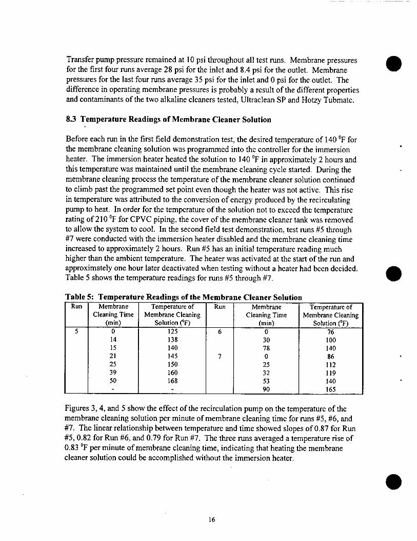
Before each run in the first field demonstration test, the desired temperature of 140 °F for the membrane cleaning solution was programmed into the controller for the immersion heater. The immersion heater heated the solution to 140 °F in approximately 2 hours and this temperature was maintained until the membrane cleaning cycle started. During the membrane cleaning process the temperature of the membrane cleaner solution continued to climb past the programmed set point even though the heater was not active. This rise in temperature was attributed to the conversion of energy produced by the recirculating pump to heat. In order for the temperature of the solution not to exceed the temperature rating of 210 °F for CPVC piping, the cover of the membrane cleaner tank was removed to allow the system to cool. In the second field test demonstration, test runs #5 through #7 were conducted with the immersion heater disabled and the membrane cleaning time increased to approximately 2 hours. Run #5 has an initial temperature reading much higher than the ambient temperature. The heater was activated at the start of the run and approximately one hour later deactivated when testing without a heater had been decided. Table 5 shows the temperature readings for runs #5 through #7.
Table 5; Temperature Readings of the Membrane Cleaner Solution Run Membrane Temperature of Run Membrane Temperature of
Cleaning Time Membrane Cleaning Cleaning Time Membrane Cleaning (min) Solution (°F) (min) Solution (°F)
5 0 125 6 0 76 14 138 30 100 15 140 78 140 21 145 7 0 86 25 150 25 112 39 160 32 119 50 168 53 140 - - 90 165
Figures 3,4, and 5 show the effect of the recirculation pump on the temperature of the membrane cleaning solution per minute of membrane cleaning time for runs #5, #6, and #7. The linear relationship between temperature and time showed slopes of 0.87 for Run #5,0.82 for Run #6, and 0.79 for Run #7. The three runs averaged a temperature rise of 0.83 °F per minute of membrane cleaning time, indicating that heating the membrane cleaner solution could be accomplished without the immersion heater.
16

Figure 3: Temperature Rise of Membrane Cleaning Solution, Run 5
180
20 25 30
Time (Minutes)
35 40 45 50
Figure 4: Temperature Rise of Membrane Cleaning Solution, Run 6
20 30 40 50
Time (Minutes)
60 70 80
17

Figure 5: Temperature Rise of Membrane Cleaning Solution, Run 7
200
! S
180
160
£T 140 ♦ 0^— "*"'
S* 120. Q
Tem
pera
ture
o o
o
>
40 .
20 .
0. I
20 40 60
Time (Minutes)
80 100 120
8.4 Analytical Test Results
8.4.1 pH
The following table presents the pH analysis for the first four test runs.
Table 6: pH Results For First Field Demonstration Test Run Feed Permeate Retentate Rinse Water Membrane Cleaner
Solution #1 Prerun 10.0 - - 8.9 12.2 Postrun - 9.9 9.9 12.2 12.6 #2 Prerun 9.9 - - 11.7 12.6 Postrun - 9.9 9.9 11.8 12.1 #3 Prerun 10.1 - - 5.1 10.7 Postrun - 10.0 10.0 9.6 9.8 #4 Prerun 10.0 - - 9.6 9.8 Postrun - 10.0 10.0 9.6 9.8
•
18
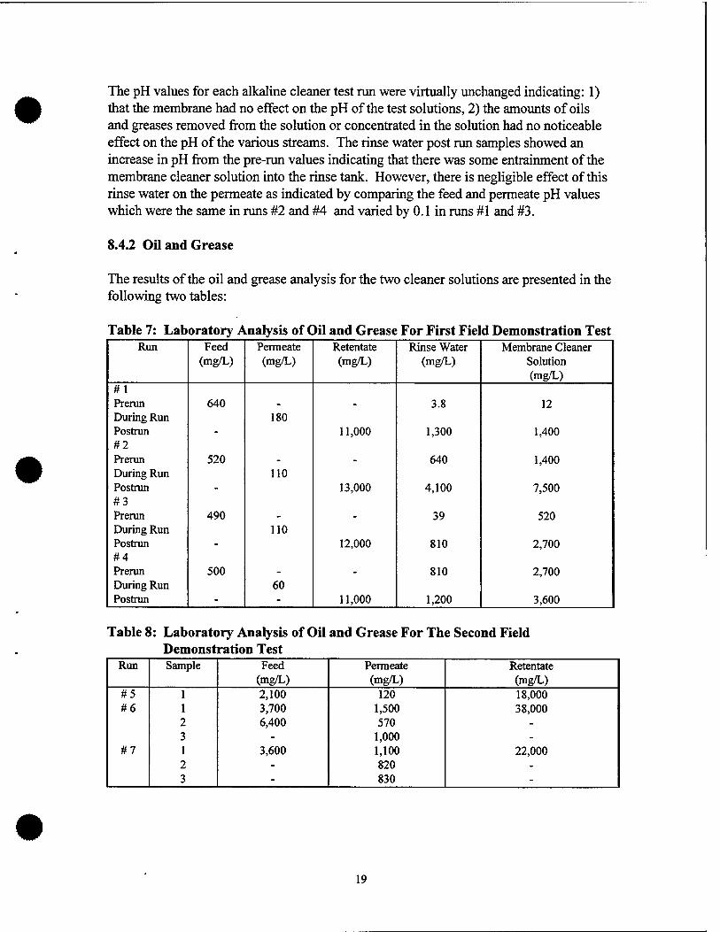
The pH values for each alkaline cleaner test run were virtually unchanged indicating: 1) that the membrane had no effect on the pH of the test solutions, 2) the amounts of oils and greases removed from the solution or concentrated in the solution had no noticeable effect on the pH of the various streams. The rinse water post run samples showed an increase in pH from the pre-run values indicating that there was some entrainment of the membrane cleaner solution into the rinse tank. However, there is negligible effect of this rinse water on the permeate as indicated by comparing the feed and permeate pH values which were the same in runs #2 and #4 and varied by 0.1 in runs #1 and #3.
8.4.2 Oil and Grease
The results of the oil and grease analysis for the two cleaner solutions are presented in the following two tables:
Table 7: Laboratory Analysis of Oil and Grease For First Field Demonstration Test Run Feed Permeate Retentate Rinse Water Membrane Cleaner
(mg/L) (mg/L) (mg/L) (mg/L) Solution (mg/L)
#1 Prerun 640 - - 3.8 12 During Run 180 Postrun - 11,000 1,300 1,400 #2 Prerun 520 - - 640 1,400 During Run 110 Postrun - 13,000 4,100 7,500 #3 Prerun 490 - - 39 520 During Run 110 Postrun - 12,000 810 2,700 #4 Prerun 500 - - 810 2,700 During Run 60 Postrun - - 11,000 1,200 3,600
Table 8: Laboratory Analysis of Oil and Grease For The Second Field Demonstration Test
Run Sample Feed Permeate Retentate (mg/L) (mg/L) (mg/L)
#5 1 2,100 120 18,000 #6 1 3,700 1,500 38,000
2 6,400 570 - 3 - 1,000 -
#7 1 3,600 1,100 22,000 2 - 820 - 3 - 830 -
19

Conventionally, EPA Standard Methods 413.1 and 418.1 are used to determine oil and grease concentrations. The above values for oil and grease must be carefully examined due to the background interference inherent in the method of analysis, presumably caused by the presence of solvent-extractable organics in the cleaner in the form of surfactants and additives, aside from the oil and grease contaminants in the solutions measured. According to the manufacturer of the alkaline cleaner used in the first field test, Ultraclean SP contains 7.95 % organics by weight. None of the organics are considered volatile by testing using EPA Method 24. According to the manufacturer of the alkaline cleaner used in the second field demonstration test, Hotze Tubmate General Purpose Liquid, contains 6% (by weight) total organic material. Of the total organic material, 2% contains volatile organic compounds (VOCs). Considering that this spent cleaner had been used frequently for a minimum of one year and in one case two years, the VOCs would have completely evaporated leaving 4% of organic material in the alkaline cleaner. A total of 90 gallons of spent Hotze Tubmate were collected from 4 different aqueous parts washers. Assuming the manufacturer's recommended dilution factor of 4 fluid ounces of alkaline cleaner per gallon of water, a total of 2.81 gallons of cleaner were used to make up the original baths. Of this amount, 4 % (0.11 gallons) is considered to be the remaining organic material (0.125% of the total 90 gallons collected). Correcting the drag out of organic surfactants that occurs over high usage of the cleaner, the total hydrocarbon content in the form of surfactants/additives is estimated to be negligible compared to the hydrocarbon content in the form of oil and grease. Therefore it is reasonable to assume that the above analytical results in Table 8 are representative of the oil and grease content found in the collected samples. The results in Table 7 are also assumed to be representative oil and grease samples due to the surfactant drag out factor.
Table 9 shows the percent decrease of oil and grease in the alkaline cleaner permeate and the concentration factor of the retained waste end product for all the test runs. The percent decrease indicates the proportion of oil and grease removed from the feed by the membrane and is calculated by subtracting the permeate value from the feed value and dividing the difference by the feed value and multiplying by 100. The oil and grease concentration factor indicates the degree of concentration of oil and grease in the waste end product compared to the original feed. The factor shows that the contaminants were transported into a much more concentrated form. This factor is equal to the concentrate value divided by the feed value. The test run samples showed fairly consistent results for both field demonstration tests. In the first field demonstration test, runs #1 through #4, single samples were collected for the feed, permeate, and retentate streams. The feed, permeate, and retentate values for the four runs ranged from 490 to 640 mg/L, 60 to 180 mg/L, and 11,000 to 13,000 mg/L respectively. The feed, permeate, and retentate values averaged 537.5 mg/L, 115 mg/L, and 11,750 mg/L respectively. The percent decrease of oil and grease ranged from 71.88 % to 88.00 % and averaged 79.07 %. The concentration factor ranged from 17.19 to 25.00 and averaged 22.71.
20

Table 9: Oil and Grease Removal Run Sample Feed Permeate Retentate Percent Decrease of Concentration
(mg/L) (mg/L) (mg/L) O&G In Permeate (%)
Factor
#1 640 180 11,000 71.88 17.19 #2 520 110 13,000 78.85 25.00 #3 490 110 12,000 77.55 24.50 #4 500 60 11,000 88.00 22.00 #5 2,100 120 18,000 94.29 8.57 #6 3,700 1,500 38,000 79.74* 7.52
2 6,400 570 - 3 - 1,000 -
#7 1 3,600 1,100 22,000 74.54* 6.11 2 - 820 - 3 - 830 -
In the second field demonstration test, runs #5 through #7, one to three samples were collected from the three streams. The feed, permeate, and retentate values ranged from 2,100 to 6,400 mg/L, 120 to 1,500 mg/L, and 18,000 to 38,000 mg/L respectively. The feed, permeate, and retentate values averaged 3,950 mg/L, 848.5 mg/L, and 26,000 mg/L respectively. The percent decrease of oil and grease ranged from 74.54 % to 94.29 % and averaged 82.86 %. The concentration factor ranged from 6.11 to 8.57 and averaged 7.40.
Table 10 presents the mass balance analysis for the second field demonstration test. Runs #5 through #7, showed a difference between the theoretical and actual feed values of less than 15 percent. The difference ranged from 3.88 to 14.75 percent and averaged 11.05 percent, indicating consistent results. A mass balance analysis was not performed on runs #1 through #4 due to inconsistent flow and volume readings resulting from start up problems. The problems encountered included power interruptions, membrane fouling, and timer adjustments which affected the accuracy of the flow controls. This prevented an accurate determination of the mass of oil and grease in the retentate.
21
Table 10: Mass Balance Analysis of Oil And Grease For Second Field Test RUN FEED PERMEATE RETENTATE FEED Percent
(Actual) (Theoretical) Difference (%)
RUN 5 Volume (L) 339.33 294.85 44.47 Oil and Grease (mg/L) 2,100 120 18.000 Oil and Grease (mg) 712.583 35,382 800,527 835,910 -14.75
RUN 6 Volume (L) 388.08 343.68 44.40 Oil and Grease (mg/L) 5,050* 1,023* 38.000 Oil and Grease (mg) 1,959,784 351,697 1,687,126 2,038.823 -3.88
RUN 7 Volume (L) 421.08 376.61 44.47 Oil and Grease (mg/L) 3,600 917* 22,000 Oil and Grease (mg) 1,515,892 345,224 978.422 1,323.646 + 14.52
* Averaged value fn )m multipli i samples col ected.
8.4.3 Membrane Cleaner Solution
One of the objectives of the field testing was to determine the number of times the membrane cleaner solution could be reused before it became ineffective as indicated by diminished permeate flowrates. The membrane cleaning solution, used for all but the first two test runs, was comprised of mixing approximately 8 oz. of LiquiGel Cascade Dishwashing Detergent in 25 gallons of deionized water. Fresh batches of membrane cleaner solutions were used on the 1st, 3rd, 5th, and 7th runs. The membrane cleaner solutions were changed out prematurely in order to correct problems associated with actuated valves and to perform other system modifications. It is estimated that the membrane cleaner solution can typically be reused a minimum of 6-7 times before it will become ineffective, however, reuse is dependent upon the degree of contamination of the alkaline cleaner processed. Processing spent alkaline cleaner heavily loaded with sludge would necessitate a more frequent changeout of membrane cleaner solution.
In the final run, 63 gallons of used membrane cleaner solution, Lemon Cascade LiquiGel (Automatic Dishwashing Detergent) was processed through the system to investigate the capability of the unit to minimize the volume of used membrane cleaning solution. The recycling process generated 51.20 gallons of permeate and 11.75 gallons of retentate. A total of seven samples were collected from the feed, permeate, and retentate streams and analyzed for oil and grease using EPA Method 413.1. Table 11 presents the sampling results from the membrane cleaner solution run.
22

Table 11: Laboratory Analysis of Oil and Grease in the Used Membrane Cleaner Solution
Run Sample Feed
(mg/L)
Permeate
(mg/L)
Retentate
(mg/L) #8 1
2 3
500 390
31.00 6.30 16.00
7,500 7,300
The feed, permeate, and retentate values for oil and grease found in the used Lemon Cascade LiquiGel ranged from 390 to 500 mg/L, 6.30 to 31 mg/L, and 7,500 to 7,300 mg/L respectively. The feed, permeate, and retentate values averaged 445 mg/L, 17.77 mg/L, and 7,400 mg/L respectively. The percent decrease of total hydrocarbon content in the form of surfactants, additives, and oil and grease averaged 96.01 % and the concentration factor averaged 16.63. The above oil and grease values in Table 11 may also include the hydrocarbon content present in the detergent's formula which would cause background interference in the method of analysis due the extractable hydrocarbons as previously mentioned in Section 8.4.2. Since the percentage of hydrocarbons in the Cascade solution is considered proprietary information by the manufacturer and the membrane's rejection rate of the surfactants in the Cascade solution is unknown, a mass balance could not be performed. Nonetheless, the above results indicate that the filtration system is effective in removing oil and grease from the membrane cleaner solution. Further investigation may show the possibility of using the filtration system to recycle the membrane cleaner solution.
9.0 FURTHER CONSIDERATIONS
9.1 Volumetric Reduction of Hazardous Waste
The system was designed to service the Better Engineering aqueous parts washers, models F-4000-P and F-3000 with sump capacities of 140 and 75 gallons respectively, typically procured through the Navy's Pollution Prevention Procurement Program. Processing at maximum capacity of 140 gallons, the unit yields a 92% volumetric reduction in hazardous waste for a single run. If processing at maximum capacity and disposing the membrane cleaner solution after the seventh use as recommended, the unit yields an 88% volumetric reduction of total hazardous waste generated. To service parts washers with larger sump capacities the system can also be modified by increasing the size of the permeate tank or by connecting an additional permeate tank. This would result in greater volumetric reductions but may require the system to be used in a stationary position.
9.2 Membrane Storage
U.S. Filter, the manufacturer of the ceramic membrane, recommended the membrane be stored wet at all times. However, the manufacturer's experience with ceramic
23

membranes was limited to continual usage in dedicated systems and did not include periodic usage of a mobile system. Therefore, guidance could not be offered with respect to periodic usage of ceramic membranes. In the first field demonstration test the membrane was stored wet after each use. However, after the system was returned for in- house modifications, the membrane was afterwards stored dry for periods ranging between 8 and 19 days with no noticeable decrease in permeate flowrate. It appears that the membrane can be stored dry between usage without detrimental effect provided that it is properly cleaned and rinsed after each use.
10.0 CONCLUSIONS AND RECOMMENDATIONS
The objectives of the field demonstration test program were to: 1) determine the ability of the recycling system to remove oil and grease from a spent alkaline cleaner and from accumulated spent membrane cleaning solution, 2) determine membrane fouling tendencies by conducting clean water permeability tests and by monitoring permeate flowrates, 3) determine and evaluate the most effective membrane cleaning process (i.e. duration of membrane self-cleaning process, membrane cleaner solution, temperature, flow configuration), 4) determine the number of times the membrane cleaning solution can be reused before rendered ineffective, 5) determine the system's utility requirements for the development of an operating cost estimate.
The demonstrated test results and conclusions are summarized below:
• Analytical test results showed that compared to the feed stream, the concentration of oil and grease in the permeate was reduced by 79% in the first field demonstration tests and by 83% in the second field demonstration tests. Thus, the system is effective in removing oil and grease from the tested spent alkaline cleaners.
• Comparing the final CWP value, measured at 2.5 gpm at 143 °F, to the benchmarked CWP value, measured at 2.3 gpm at 145 °F, the membrane showed no decline in permeability. This indicates that the systems cleaning regime (the Cascade LiquiGel detergent circulated through the membrane at a minimum of 140 °F for an hour) maintains membrane permeability.
• Based on the performance of the membrane's self cleaning regime and the CWP values measured throughout testing, it is estimated that the membrane cleaner solution could typically be reused 6-7 times before rendering it inadequate. Processing a spent alkaline cleaner, heavily contaminated with sludge, may necessitate a more frequent changeout of membrane cleaner solution.
• Test runs conducted without the use of the immersion heater showed a temperature rise, via the heat generated by the recirculation pump, of close to 1 °F per minute of membrane cleaning time. Thus, heating the membrane cleaning solution can be effectively accomplished without the use of the immersion heater.
24
•
• The membrane showed no evidence of fouling after periods of dry storage. Therefore, the membrane can be stored dry without detrimental effect between usage provided that it is properly cleaned and rinsed after each use.
• The system can reduce the volume of hazardous waste generated from alkaline cleaning by 88 percent. This is based on operating the system at a full capacity of 140 gallons and using the membrane cleaner solution seven times.
The following recommendations are based on the demonstrated test results:
• A non-sudsing type of detergent is recommended for use as the membrane cleaning solution.
• Before the effectiveness of recycling spent membrane cleaning solution can be fully determined, the hydrocarbon content of the detergent and the membrane's rejection rate of the detergent's hydrocarbon components needs to be established.
Although 964 gallons of spent alkaline cleaner were processed through the system during the two field tests, additional testing would permit the verification of the long term efficiency of the self cleaning regime.
Although the heat generated by the recirculation pump, of close to 1 °F per minute of membrane cleaning time, can be controlled by a timer, it is recommended that the immersion heater be removed from the original design and the system rewired to terminate the membrane cleaning mode once the membrane cleaning solution reaches 180°F.
Before rendering the membrane cleaner solution ineffective after the sixth or seventh use, it would be desirable that this be verified with additional testing.
25

11.0 REFERENCES
Chen, A.S.C., E. H. Drescher, A. J. Pollack, L Wang. 1997. Using Ceramic Crossflow Filtration To Recycle Spent Nonionic Aqueous-Based Metal Cleaning Solution: Pilot- Scale Testing, CR 96.004. Report Prepared for Naval Facilities Engineering Service Center, Port Hueneme, CA.
Chen, A.S.C., E. H. Drescher, B. Sass, D. E. Giammer, T. Hutson. A. J. Pollack. 1996. Using Ceramic Crossflow Filtration To Recycle Spent Nonionic Aqueous-Based Metal Cleaning Solutions, CR 97.004. Report Prepared for Naval Facilities Engineering Service Center, Port Hueneme, CA.
26

APPENDIX A
MASS BALANCE CALCULATIONS
A-l

Mass balance calculations are based on analytical results for oil and grease concentrations in samples collected during Run #6.
Average Feed Concentration = (3700 (mg/L) + 6400 (mg/L)) / 2 = 5050 (mg/L)
Average Permeate Concentration = (1000 (mg/L) + 570 (mg/L) + 1500 (mg/L)) / 3 = 1023.33 (mg/L)
Average Concentrate Concentration = 38000 (mg/L)
Feed Volume = 102.53 (gal) * 3.785 (L/gal) = 388.08 (L)
Permeate Volume = 90.8 (gal) * 3.785 (L/gal) = 343.68 (L)
Concentrate Volume = 11.73 (gal) * 3.785 (L/gal) = 44.40 (L)
Amount of Oil and Grease In Feed (Experimental Value) = 5050 (mg/L) * 388.08 (L) = 1959784 (mg)
Amount of Oil and Grease In Permeate = 1023.33 (mg/L) * 343.68 (L) = 351697 (mg)
Amount of Oil and Grease In Concentrate = 38000 (mg/L) * 44.40 (L) = 1687126 (mg)
Amount of Oil and Grease In Feed (Theoretical Value) = 351697 (mg) + 1687126 (mg) = 2038823 (mg)
Percent Difference Of Mass Of Oil and Grease In Feed = (Theoretical Value - Experimental Value) / Theoretical Value * 100 = (2038823 (mg) - 1959784 (mg)) / 2038823 (mg) * 100 = 3.88 %
Oil and Grease Concentration Factor = 1687126 (mg) / 1959784 (mg) = 7.52
Percent Decrease of Oil and Grease In Permeate = (1959784 (mg) - 351697 (mg)) / 1959784 (mg) * 100
= 79.74 %
A-2

APPENDIX B
MATERIAL SAFETY DATA SHEETS FOR FIELD TESTING OF THE
MOBILE ALKALINE CLEANER RECYCLER
B-l

MAR-14-97 03.14 FROM< ID. PACE 2/8
DURA-CHEM, INC.
PRODUCT INFORMATION BULLETIN
ULTRA CLEAN S?
Introduction ULTRA CLEAN SP is a water based detergent, designed for spray washing of metal parts in a recirculating parts washer. It is useful for removing stubborn grease, oil and grime. Replaces solvent degreasers. Rinsing is usually not required. Formulated to prevent rust
Features: Benefits:
Mo volatile organic compounds Water based No Hazardous fumes Easily waste treatable
Exceptional cleaning
Not regulated by A.Q.M.D. Will not burn Worker Safely Normal waste treatment methods No foam above 100 F
Operating Data: Time: Temperature: Concentration:
As required 130 F -160 F 20-30% by volume
Bath Makeup; 1. Fill reservoir 2/3 full with water. 2. Add detergent and mix. 3. Finish fill tank to working level wrth water. 4-. Turn on heat
Safety Procedures: Read, understand and follow all safety procedures detailed in Material Safety Data sheet provided. Do not work with product until you understand the safely requirements.
This pubOcation certain* Information and (eeoamendatSons baaed upon data obtained from •owe** no warranty or guarantee bexpressed or implied
oonoidorod rattap la and ba laved to be correct, however.

MAR-14-97 09=15 FROM: ID:
MATERIAL SAKKT-y OATA SHEET
«...-■•-■-•«
TRADE NAKBi. ULTRA CLEM SP.
XAXUFACTORKR'S NAME» DURA-CIIEM, INC.
ADDRESSl 1060-B ORTEGA WAY 'PLACENTIA, CA. 92670
P80NB NUMBER FOR ADDITIONAL INFORMATION: (714) 630-4100
DATS PREPARED OR REVISED: MLY 13, 1995
NAME OP PREPARER». JOHN W. MÄSSELL
PAGE 3/8
II. HAZARDOUS INGREDIENTS
• JO.MPONF.NTS/IDENTIFY INFORMATIONS I .• OSHA/PKI. ACC r «/TLV .CASI ►
DETERGENT/ETHOXYLATES
BORAX
. \,-
1-3
1-3
N/E
N/E
N/E
. 1 mg/m1 TW*
N/E
1303-96-4
•
SPECIAL ■ NOTESt NPPA HAZARD RATING
?EL ÄND TLV ARE APPLICABLE TO AIRBÖRN MIST. GENERATION OF
• :-;IST WOULD NOT BE EXPECTED THROUGH NORMAL USE OF THIS PRODUCT". •.
r ■ TTT"-*"' ■ I r y -in«w>
/C : 0 J\^ ■ . . .
Bealth / , N/ , \ Reactivity (Blue) \ l yT\ l y (Yellov)
' Not & required category •• .
'A= Not Applicable N/E* Not Established p* Not Pound
NONE
Special Hazard
4-EXTREME 3-HIGS 2-MODERATE 1-SLIGHT O-INSIGMIFlCAirr

MAR-14-97 09-15 FROM■ ID. PACE 4/8
III. PHYSICAL PROPERTIES
Vapor density(air-l): N/E (Similar to vater)
Specific gravity; . Greater than water
Solubility in water: Complete {Material is a vater-based detergent)
Vapor pressure mmHg at 20 degree C: • N/E (Similar to water)
Melting point or range, degree F: 32°p
Boiling point or range, degree F: 212°F
Evaporating rate(butyl ecetate«l) : N/E (Similar to water)
Appearance and odor: pale yellow.liquid, slight sharp odor, slight . " haze. pH (20% in water) 9.5-10
HOW TO DETECT THIS. SUBSTANCE* (va mi ng properties or substance as a gas, vapor, dust or mist)
IV. FIRE ANC EXPLOSION
Flash point, degree F(give method) N/A
Auto ignition temperature, degree F N/A
Flammable limits in air, volume %: N/A Lower(LEL) Upper(UEL)
Fire extinguishing materials:
water spray
foam -, .I'J"
carbon dixoide
dry chemical -
other"
Special fire, fighting procedures: Material is a water-solution*and will not burn under ordinary conditions. Evaporation of the water will leave some combustible material, which will liberate traces of sulfur and phosphorus oxides and possibly carbon monoxide if somehow ignited. Kear self-contained breathing apparatus and protective clothing if fighting fire.
• »!'**•' *
Unusual fire and explosion hazardsr NONE
Paje ?. of. 6;.

MAR-14-97 09=15 FROM- ID. PACE S/S
V. HEALTH HAZARD INFORMATION.
SYMPTOMS OF OVER EXPOSURE FOR EACH POTENTIAL ROUTE OF EXPOSURE. .
inhaled: Mist, irritating to nose, lungs ^^f"1^^^3965' Not .expected to be a potential route of exposure.
Contact with skin or eyes:' .Minor irritation expected. . s^_n irritation from defatting expected.
Absorbed through skin: product contains small amount of Borax which can be absorbed through damaged skin. Prolonged or repeated exposure could cause harmful effect.
Swallowed« Not expected to be a potential route oj exposure. Gastrointestinal irritation, nausea» vomiting, diarrhea and possible Borax poisoning.
HEALTH EFFECTS 0R:RISKS'FROM EXPOSURE. coaep is (Explain in lay terms. Attach extra page.if more space is needed.)
Acute: Eyes - Causes burning and irritation. Skin irritation.
Chronic» As Vith most detergents, contact with the eyes will cause immediate irritation. Prolonged contact with bare skin can cause defatting, drying, chapping and possible skin absorption..
FIRST AID: EMERGENCY PROCEDURES
Eye contact» Wash immediately with clean water for fifteen minutes. Get medical attention. Lift .upper and lower lids when flushing.- ,
Skin contact: wash with clean water for 15 or more minutes. Remove and launder contaminated clothing before re-use,
Inhaled: Remove from area where product mist is.present. Restore breathing if necessary. Seek medical attention at once.
•Swallowed: if victim awake, give milk or water and induce vomiting. Get medical attention at once.
• sv . v.
Page 3 of 6
t -. ■* •

MAR-14-97 09.15 FROM> ID. PACE B/S * * i * * * i
V, HEALTH HAZARD IN'.'ORMATION CONTINUED. ; .... . ..^^ .
SUSPECTED- CANCER AGENT?
x NO»--« Th/is product's ingredients are not found in the lists below. '
YES: FEDERAL OSHA NTP ... .' IARC
California employers using CAL/OSHA regulated carcinogens must register with CAL/OSHA. The CAL/OSHA and FEDERAL OSHA caccinogens lists ace similar.
* MEDICAL CONDITIONS AGGRAVATED BY EXPOSURE»
Dry or chapped skin would.be aggravated by excessive"contact with product-. No other medical conditions known that would be aggravated by material. .
VI; REACTIVITY DATA
Scabililty: X Stable ■_ Unstable
Conditions to avoid» Strong acids. ••■ i
Incompatibility(material to avoid): Strong oxidizing agents, acids,
Hazardous decomposition products(including combustion products}»
Oxides of carbon', sulfur, phosphorus, and suifuric and • phosphoric acids.
Hazardous polymerization» May occur x Will not occur
:>;: > j itr.o\- oot'bf. f :
Paye 4 of 0

MAR-14-S7 09.15 FROM< ID: PAGE 7/B
• Vir. SPIOI.;' LBAK ftND DISPOSAL PROCEDURES.
spill response propres (include employee Pro"ct1^ "•""^•^.^ P Spill, en be diked or otherwise «"«£•*[*»*L^^tVÄal^f o?"
r
Preparing wastes for disposal: . 'container types, neutralination, etc.) , „,.___
Store in DOT-approved waste containers. .Keep out of sewers, storm drains, surface waters and soils.
>:, ,•>"•-!.-
NOTE: Dispose of all waste in accordance with federal, >t». and local regulations.
VIII. SPECXM. HANOLINC INFORMATION
Ventilation and engineering controls: . •
Normal room ventilation
Respiratory protection (type)»
Normally none required t
* * •
Eye protection(type)i Splash-proof chemical goggles or full face shield
• * Glove»(»peoify material)» •
Rubber gloves
Other clothing and equircent:
. Rubber apron, long sleeved shxrfc
Page 5 of € '

MAR-14-97 09.IB FROM- ID. PAGE 8/8
Will', SPECIAL HANDLING INFORMATION (CONT'D),
Work practices, hygienic.practices :
Remove and wash contaminated clothing before reusing. Remove even minor spills from work area.
Other handling end storage requirements: .
Do not store in aluminum,Copper or their alloys
Prorterct ive' measures during maintenance of contaminated equipment:
Wear recommednded eye and skin protection
IX. SARA TITLE III SECTION 313
As required by Section 313 of SARA Title III of 1968 »d 40 CFR part.372, this product contains the follov/ing itemi;» in a
-repor'table quantity. Oo not detach or separate this sect.or. £rcr? trie ethers sect ions'.of this MSOS. Copying »r\'J red is tc :&■.;'. .or» of tn:s hSOS'shall include the copying and tedisuioycion '- tr.is notification,
INGREDIENT • CASl ' - WT\
NONE
OTHER REGULATOR* INFORMATION
THIS PRODUCT CONTAINS THE FOLLOW I NC ' CHEM ICACCS) CGNSJOEftcD 2>V THE STATE OF CALIFORNIA'S SAFE ORINKING WATER AND TOXIC ENFORCEMENT ACT OF 1986 (PROPOSITION 65) AS CAUSING CANCER OR RE P RGSUCT I V E TÖXIC.IT* AND' FOR WHICH WARNING ARE NOW REQUIRED.
CHEMICAL CAS NO. . I WT
NONE
Page 6 Of 6
• DOD Hazardous Materials Information System
DoD 6050.5-LR AS OF July 1996
Proprietary Version - For U.S. Government Use Only FSC: 6810 NUN: OON014604 Manufacturer's CAGE: 60928 Part No. Indicator: A Part Number/Trade Name: SODIUM HYDROXIDE PELLETS, 99.99%, (SUP DAT)
Nuclear Water Data
This is not a Nuclear Water Chemical NUN.
Standard PMS Identification Number Data
This is not a Standard PMS Identification Number NUN.
General Information
Item Name: Company's Name: ALDRICH CHEMICAL COMPANY Company's Street: Company's P. 0. Box: 355 Company's City: MILWAUKEE Company's State: WI Company's Country: US Company's Zip Code: 53201 Company's Emerg Ph #: Company's Info Ph #: 414-273-3850 Distributor/Vendor # 1: Distributor/Vendor # 1 Cage: Distributor/Vendor # 2: Distributor/Vendor # 2 Cage: Distributor/Vendor # 3: Distributor/Vendor # 3 Cage: Distributor/Vendor # 4: Distributor/Vendor # 4 Cage: Safety Data Action Code: Safety Focal Point: N Record No. For Safety Entry: 001 Tot Safety Entries This Stk#: 001 Status: SMJ Date MSDS Prepared: 29MAY90 Safety Data Review Date: 27MAR91 Supply Item Manager: MSDS Preparer's Name: Preparer's Company: Preparer's St Or P. O. Box: Preparer's City: Preparer's State: Preparer's Zip Code: Other MSDS Number:

Report for NUN: 0ONO 14604
MSDS Serial Number: BKLDG Specification Number: Spec Type, Grade, Class: Hazard Characteristic Code: C2 Unit Of Issue: Unit Of Issue Container Qty: Type Of Container: Net Unit Weight: NRC/State License Number: Net Explosive Weight: Net Propellant Weight-Ammo: Coast Guard Ammunition Code:
Ingredients/Identity Information
Proprietary: NO Ingredient: SODIUM HYDROXIDE (SARA III) Ingredient Sequence Number: 01 Percent: 99.99 Ingredient Action Code: Ingredient Focal Point: N NIOSH (RTECS) Number: WB4900000 CAS Number: 1310-73-2 OSHA PEL: 2 MG/M3 ACGIH TLV: C 2 MG/M3; 9293 Other Recommended Limit: N/K
Physical/Chemical Characteristics
Appearance And Odor: WHITE PELLETS. ODORLESS (FP N) Boiling Point: 2534F,1390C Melting Point: 604F,318C Vapor Pressure (MM Hg/70 F): <18 @ 20C Vapor Density (Air=l): >1 Specific Gravity: 2.130 De imposition Temperature: N/K E-v„,.>oration Rate And Ref: NOT APPLICABLE Sol-ability In Water: 40G IN 100 ML @ 0C Percent Volatiles By Volume: N/K Viscosity: pH: N/K Radioactivity: Form (Radioactive Matl): Magnetism (Milligauss): N/P Corrosion Rate (IPY): N/K Autoignition Temperature:
Fire and Explosion Hazard Data
Flash Point: NONCOMBUSTIBLE Flash Point Method: N/P Lower Explosive Limit: N/A Upper Explosive Limit: N/A

Report for NUN: 00N014604
Extinguishing Media: USE EXTINGUISHING MEDIA APPROPRIATE TO SURROUNDING FIRE CONDITIONS. DO NOT USE WATER. Special Fire Fighting Proc: WEAR NIOSH/MSHA APPROVED SCBA AND PROTECTIVE CLOTHING TO PREVENT CONTACT WITH SKIN AND EYES. Unusual Fire And Expl Hazrds: EMITS TOXIC FUMES UNDER FIRE CONDITIONS.
Reactivity Data
Stability: YES Cond To Avoid (Stability): ABSORBS CO*2 FROM AIR. WATER (FP N). Materials To Avoid: STRONG OXIDIZING AGENTS, STRONG ACIDS, ORGANIC MATERIALS, CHLORINATED SOLVENTS & ORGANIC PEROXIDE. Hazardous Decomp Products: NATURE OF DECOMPOSITION PRODUCTS NOT KNOWN. Hazardous Poly Occur: NO Conditions To Avoid (Poly): NOT RELEVANT
Health Hazard Data
LD50-LC50 Mixture: LD50:(IPR,MUS) 40 MG/KG. Route Of Entry - Inhalation: YES Route Of Entry - Skin: YES Route Of Entry - Ingestion: NO Health Haz Acute And Chronic: ACUTE: HARMFUL IF SWALLOWED, INHALED OR ABSORBED THRU SKIN. MATL IS EXTREMELY DESTRUCTIVE TO TISS OF MUC MEMB & UPPER RESP TRACT, EYES & SKIN. CAUSES SEV BURNS. INHAL MAY BE FATAL AS A RESULT OF SPASM, INFLAM & EDEMA OF LARYNX & BRONCHI, CHEM PNEUM & PULM EDEMA. Carcinogenicity - NTP: NO Care inogeni city - I ARC: NO Carcinogenicity - OSHA: NO Explanation Carcinogenicity: NOT RELEVANT Signs/Symptoms Of Overexp: BURNING SENSATION, COUGHING, WHEEZING, LARYNGITIS, SHORTNESS OF BREATH, HEADACHE, NAUSEA AND VOMITING. Med Cond Aggravated By Exp: NONE SPECIFIED BY MANUFACTURER. Emergency/First Aid Proc: EYES & SKIN: IMMED FLUSH W/COPIOUS AMTS OF WATER FOR AT LEAST 15 MIN WHILE REMOVING CONTAM CLTHG & SHOES. WASH BEFORE REUSE. DISCARD CONTAM SHOES. ASSURE ADEQ FLUSHING OF EYES BY SEP LIDS W/ FINGERS. INHAL: REMOVE TO FRESH AIR. IF NOT BRTHG GIVE ARTF RESP. IF BRTHG IS DFCLT, GIVE OXYGEN. CALL MD. INGEST: RINSE MOUTH W/WATER; DO NOT INDUCE VOMIT; DRINK 8-10 OZ WATER; CALL MD IMMED (FP N).
Precautions for Safe Handling and Use
Steps If Matl Released/Spill: EVAC AREA. WEAR NIOSH/MSHA APPROVED SCBA, RUBBER BOOTS & HEAVY RUBBER GLOVES. SWEEP UP, PLACE IN A BAG AND HOLD FOR WASTE DISPOSAL. VENTILATE AREA AND WASH SPILL SITE AFTER MATERIAL PICKUP IS COMPLETE. Neutralizing Agent: NONE SPECIFIED BY MANUFACTURER. Waste Disposal Method: SM QTYS: CAUTIOUSLY ADD TO LRG STIRRED EXCESS OF WATER. ADJUST PH TO NEUTRAL, SEPARATE ANY INSOLUBLE SOLIDS OR LIQUIDS & PACKAGE THEM FOR HAZ-WASTE DISP. FLUSH AQUEOUS SOLN DOWN DRAIN W/PLENTY OF WATER. THE HYDROLYSIS & NEUTRALIZATION (SUPP DATA) Precautions-Handling/Storing: DO NOT BREATHE DUST. KEEP TIGHTLY CLOSED.
Report for NUN: 00N014604
STORE IN A COOL DRY PLACE. Other Precautions: DO NOT GET IN EYES, ON SKIN AND CLOTHING. AVOID PROLONGED OR REPEATED EXPOSURE. READILY ABSORBED THRU SKIN. TOXIC. CORROSIVE. EXTREMELY HYGROSCOPIC. AIR SENSITIVE. CONT W/ALUMINUM, TIN & ZINC LIBERATES HYDROGEN GAS. CONT WITH (SUPP DATA)
Control Measures
Respiratory Protection: WEAR APPROPRIATE NIOSH/MSHA APPROVED RESPIRATOR. Ventilation: USE ONLY IN A CHEMICAL FUME HOOD. Protective Gloves: CHEMICAL RESISTANT GLOVES. Eye Protection: CHEM WORK GOGGLES, FACESHLD OPTL (FP N). Other Protective Equipment: PROTECTIVE CLOTHING, FACESHIELD (8-INCH MINIMUM), SAFETY SHOWER AND EYE BATH. Work Hygienic Practices: WASH THOROUGHLY AFTER USE AND BEFORE EATING, DRINKING, SMOKING OR USING SANITARY FACILITIES (FP N). Suppl. Safety & Health Data: PART NO: SEMICONDUCTOR GRADE, 30657-6. WASTE DISP METH: RXN MAY GEN HEAT & FUMES WHICH CAN BE CONTROLLED BY RATE OF ADDN. DISPOSE OF I/A/W FEDERAL, STATE & LOCAL LAWS. OTHER PREC: NITROMETHANE & OTHER SIMILAR NITRO CMPDS CAUSES FORMATION OF SHOCK SENSITIVE SALTS.
Transportation Data
Transportation Action Code: Transportation Focal Point: N Trans Data Review Date: 91281 DOT PSN Code: NGU DOT Symbol: DOT Proper Shipping Name: SODIUM HYDROXIDE, SOLID DOT Class: 8 DOT ID Number: UNI823 DOT Pack Group: II DOT Label: CORROSIVE DOT/DoD Exemption Number: IMO PSN Code: NSX IMO Proper Shipping Name: SODIUM HYDROXIDE, SOLID IMO Regulations Page Number: 8225 IMO UN Number: 1823 IMO UN Class: 8 IMO Subsidiary Risk Label: - IATA PSN Code: WSO IATA UN ID Number: 1823 IATA Proper Shipping Name: SODIUM HYDROXIDE, SOLID IATA UN Class: 8 IATA Subsidiary Risk Class: IATA Label: CORROSIVE AFI PSN Code: WSO AFI Symbols: AFI Prop. Shipping Name: SODIUM HYDROXIDE, SOLID AFI Class: 8 AFI ID Number: UN1823 AFI Pack Group: II

Report for NUN: 00N014604
AFI Label: CORROSIVE AFI Special Prov: AFI Basic Pac Ref: 12-7 MMAC Code: N.0.S. Shipping Name: Additional Trans Data:
Disposal Data
Disposal Data Action Code Disposal Data Focal Point Disposal Data Review Date Rec # For This Disp Entry- Tot Disp Entries Per NSN: Landfill Ban Item: Disposal Supplemental Data 1st EPA Haz Wst Code New: 1st EPA Haz Wst Name New: 1st EPA Haz Wst Char New: 1st EPA Acute Hazard New: 2nd EPA Haz Wst Code New: 2nd EPA Haz Wst Name New: 2nd EPA Haz Wst Char New: 2nd EPA Acute Hazard New: 3rd EPA Haz Wst Code New: 3rd EPA Haz Wst Name New: 3rd EPA Haz Wst Char New: 3rd EPA Acute Hazard New:
Label Data
Label Required: YES Technical Review Date: 07JUN91 Label Date: 07JUN91 MFR Label Number: Label Status: G Common Name: SODIUM HYDROXIDE PELLETS Chronic Hazard: N/P Signal Word: DANGER! Acute Health Hazard-None: Acute Health Hazard-Slight: Acute Health Hazard-Moderate: Acute Health Hazard-Severe: X Contact Hazard-None: Contact Hazard-Slight: Contact Hazard-Moderate: Contact Hazard-Severe: X Fire Hazard-None: X Fire Hazard-Slight: Fire Hazard-Moderate: Fire Hazard-Severe: Reactivity Hazard-None: X Reactivity Hazard-Slight:

Report for NUN: 0ONO 14604
Reactivity Hazard-Moderate: Reactivity Hazard-Severe: Special Hazard Precautions: ACUTE:CAUSES SEVERE BURNS. DO NOT GET IN EYES, ON SKIN, OR ON CLOTHING. DO NOT BREATHE DUST. KEEP CONTAINER CLOSED. USE WITH ADEQUATE VENTILATION. WASH THOROUGHLY AFTER HANDLING. MAY BE FATAL IF INHALED. HARMFUL IF SWALLOWED, INHALED, OR ABSORBED THROUGH SKIN. CAUSES MUCOUS MEMBRANE, UPPER RESPIRATORY TRACT, EYE AND SKIN IRRITATION. Protect Eye: Y Protect Skin: Y Protect Respiratory: Y Label Name: ALDRICH CHEMICAL COMPANY Label Street: Label P.O. Box: 355 Label City: MILWAUKEE Label State: WI Label Zip Code: 53201 Label Country: US Label Emergency Number: Year Procured:

DOD Hazardous Materials Information System DoD 6050.5-LR
AS OF July 1996 Proprietary Version - For U.S. Government Use Only
FSC: 6810 NUN: 002372918 Manufacturer's CAGE: 81348 Part No. Indicator: A Part Number/Trade Name: O-N-350
General Information
Item Name: NITRIC ACID Company's Name: BOUGHT ACCORDING TO SPECIFICATION Company's Street: Company's P. 0. Box: Company 's City: Company's State: Company's Count ry: Company's Zip Code: Company's Emerg Ph #: Company's Info Ph #: Distributor/Vendor # 1: Distributor/Vendor # 1 Cage: Distributor/Vendor # 2: Distributor/Vendor # 2 Cage: Distributor/Vendor # 3: Distributor/Vendor # 3 Cage: Distributor/Vendor # 4 : Distributor/Vendor # 4 Cage: Safety Data Action Code: Safety Focal Point: D Record No. For Safety Entry: 010 Tot Safety Entries This Stk#: 012 Status: Date MSDS Prepared: 01JAN85 Safety Data Review Date: 03APR81 Supply Item Manager: CX MSDS Preparer's Name: Preparer's Company: Preparer's St Or P. O. Box: Preparer's City: Preparer's State: Preparer's Zip Code: Other MSDS Number: MSDS Serial Number: BDLXS Specification Number: O-N-350 Spec Type, Grade, Class: Hazard Characteristic Code: Cl Unit Of Issue: BT Unit Of Issue Container Qty: 80 FL OUNCES Type Of Container: BOTTLE Net Unit Weight: 7.75 LBS

Report for NUN: 002372918
NRC/State License Number: N/R Net Explosive Weight: N/R Net Propellant Weight-Ammo: N/R Coast Guard Ammunition Code:
Ingredients/Identity Information
Proprietary: NO Ingredient: NITRIC ACID (SARA III) Ingredient Sequence Number: 01 Percent: 61 Ingredient Action Code: Ingredient Focal Point: D NIOSH (RTECS) Number: QU57750 00 CAS Number: 7697-37-2 OSHA PEL: 2 PPM/4 STEL ACGIH TLV: 2 PPM/4 STEL; 9192 Other Recommended Limit:
Physical/Chemical Characteristics
Appearance And Odor: TRANSPARENT, COLORLESS TO YELLOW LIQUID WITH A PUNGENT ODOR. Boiling Point: 187F,86C Melting Point: UNKNOWN Vapor Pressure (MM Hg/70 F): 62 Vapor Density (Air=l): UNKNOWN Specific Gravity: 1.504 Decomposition Temperature: UNKNOWN Evaporation Rate And Ref: UNKNOWN Solubility In Water: COMPLETE Percent Volatiles By Volume: Viscosity: N/K pH: Radioactivity: N/R Form (Radioactive Matl): Magnetism (Milligauss): N/P Corrosion Rate (IPY): Autoignition Temperature:
Fire and Explosion Hazard Data
Flash Point: N/A Flash Point Method: N/P Lower Explosive Limit: Upper Explosive Limit: Extinguishing Media: WATER Special Fire Fighting Proc: WEAR SELF-CONTAINED BREATHING APPARATUS Unusual Fire And Expl Hazrds: REACTS EXPLOSIVELY WITH METALLIC POWDERS, CARBIDES,HYDROGEN SULFIDE AND TURPENTINE. SEE SUPPLEMENTAL.
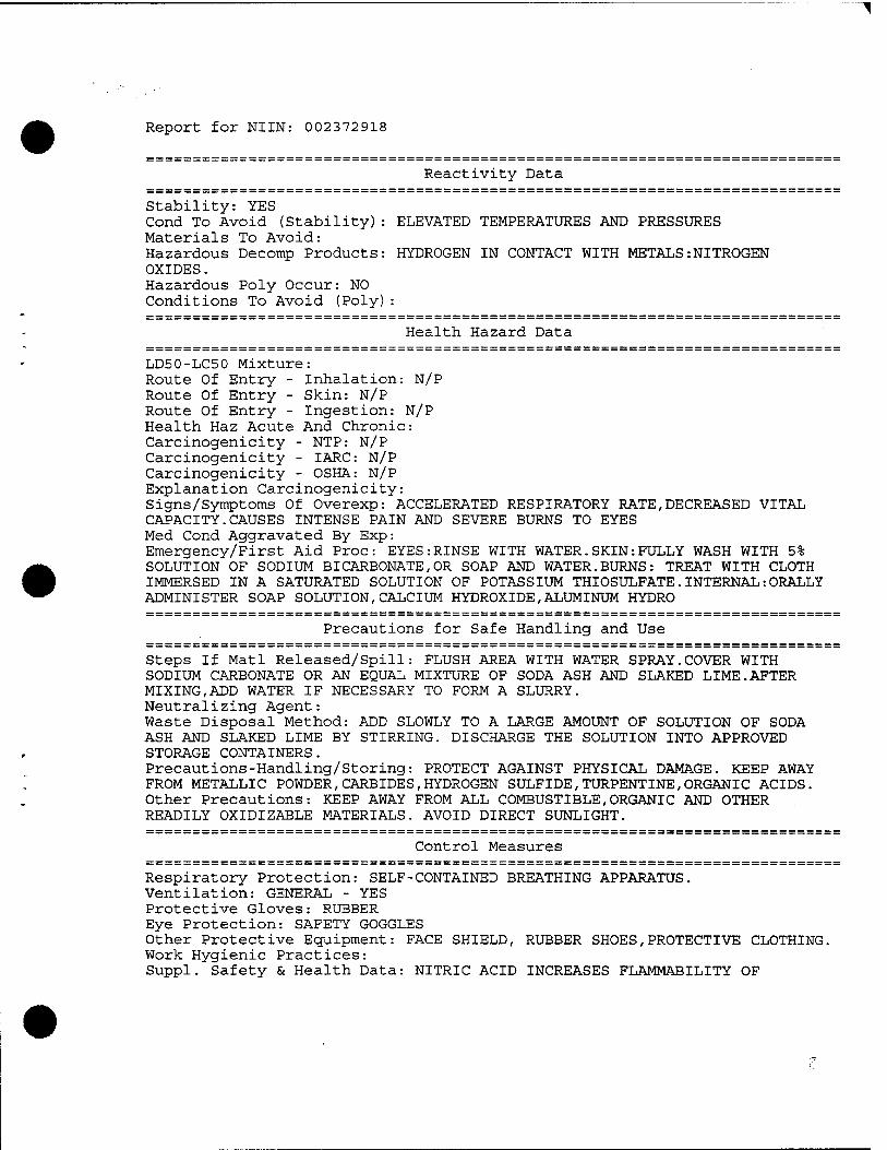
Report for NUN: 002372918
Reactivity Data
Stability: YES Cond To Avoid (Stability): ELEVATED TEMPERATURES AND PRESSURES Materials To Avoid: Hazardous Decomp Products: HYDROGEN IN CONTACT WITH METALS:NITROGEN OXIDES. Hazardous Poly Occur: NO Conditions To Avoid (Poly)
Health Hazard Data
LD50-LC50 Mixture: Route Of Entry - Inhalation: N/P Route Of Entry - Skin: N/P Route Of Entry - Ingestion: N/P Health Haz Acute And Chronic: Carcinogenicity - NTP: N/P Carcinogenicity - IARC: N/P Carcinogenicity - OSHA: N/P Explanation Carcinogenicity: Signs/Symptoms Of Overexp: ACCELERATED RESPIRATORY RATE,DECREASED VITAL CAPACITY.CAUSES INTENSE PAIN AND SEVERE BURNS TO EYES Med Cond Aggravated By Exp: Emergency/First Aid Proc: EYES:RINSE WITH WATER.SKIN:FULLY WASH WITH 5% SOLUTION OF SODIUM BICARBONATE,OR SOAP AND WATER.BURNS: TREAT WITH CLOTH IMMERSED IN A SATURATED SOLUTION OF POTASSIUM THIOSULFATE.INTERNAL:ORALLY ADMINISTER SOAP SOLUTION, CALCIUM HYDROXIDE,ALUMINUM HYDRO
Precautions for Safe Handling and Use
Steps If Matl Released/Spill: FLUSH AREA WITH WATER SPRAY.COVER WITH SODIUM CARBONATE OR AN EQUAL MIXTURE OF SODA ASH AND SLAKED LIME.AFTER MIXING,ADD WATER IF NECESSARY TO FORM A SLURRY. Neutralizing Agent: Waste Disposal Method: ADD SLOWLY TO A LARGE AMOUNT OF SOLUTION OF SODA ASH AND SLAKED LIME BY STIRRING. DISCHARGE THE SOLUTION INTO APPROVED STORAGE CONTAINERS. Precautions-Handling/Storing: PROTECT AGAINST PHYSICAL DAMAGE. KEEP AWAY FROM METALLIC POWDER,CARBIDES,HYDROGEN SULFIDE,TURPENTINE,ORGANIC ACIDS. Other Precautions: KEEP AWAY FROM ALL COMBUSTIBLE,ORGANIC AND OTHER READILY OXIDIZABLE MATERIALS. AVOID DIRECT SUNLIGHT.
Control Measures
Respiratory Protection: SELF-CONTAINED BREATHING APPARATUS. Ventilation: GENERAL - YES Protective Gloves: RUBBER Eye Protection: SAFETY GOGGLES Other Protective Equipment: FACE SHIELD, RUBBER SHOES,PROTECTIVE CLOTHING. Work Hygienic Practices: Suppl. Safety & Health Data: NITRIC ACID INCREASES FLAMMABILITY OF

PROCTER & GAMBLE MATERIAL SAFETY DATA SHEET
Laundry Ä Cleaning Products Division ivorydale Technical Center Cincinnati, Ohio 45217 Issue Pat»- 5/93
SECTION I EMERGENCY BLPBOOT iqMJURS
24 Hour P*G Operator Service 1-800-765-5516 or call local Poison Control Center.
IPSNTITY Lemon Cascade LiquiGel (Automatic dishwashing detergent). TL
OTHER Ingredients: Water softeners (potassium and/or sodium complex phosphates and/or carbonate salts), cleaning agent (chlorine bleach), dishware, flatware, and dishwasher protection agents (sodium and/or potassium silicates), water thickening agent, buffering agent, stabilizing agent, colorant, and perfume
CHEMICAL MAMR
SECTION II — HAZARDOUS MGREDIENTS/IDENTITY INFORMATION BASARPOOS IHgREPIEWTS AS DEFINED ET OSHA. 28 CTR 1910,1200
ACGLIH OSHA COMMON NAjffi CAS NO. TLV PEL
OTHER LIMITS RECOMMENDED
This alkaline mixture, when tested as a whole, is considered an eye irritant and a skin irritant within the meaning of the OSHA Hazard Communication Standard.
BOILING POTMT IT) N.A.
VAPOR PRESSPRE fMM RC1 N.A.
VAPOR DENSITY (AIR - H N.A.
SOLUBILITY IN WATER Miscible with water. Contains small amount of insoluble, colloidal size particles
gKCTTQw TTT; — msirAMTrM SPECIFIC PRIVITY ftt.0 - n
- 1.2 - 1.3 g/cc PERCENT VOLATILE BT VOUM f»l
< 1 EVAPORATION RAT« fnBnOAg , n
N.A. APPEARANCE AND OPO»
Yellow color. Thick/viscous gel. Product is perfumed.
1% solution - 10.8. ii i. . l? ? SECTTON TV — nAtmnmr-LTrr AMP REACTryiTT PftTft
rLASH POINT METHOD PSRD1 N.A.
EXPLOSIV« mew LEL N.A. UEL N.A.
EXTINCOISHINC MEDIA N.A.
SPECIAL FIRE PICHTTMS PROCEDTIMS None
ÜKOSÜAL PIRE BREAM» None
STABILITY Stable. May lose available chlorine with time.
C0HDITIONS TO AVOID None known.
INCOMPATIBILITY (Materials to .»alrii Strong acids, ammonia or ammonia containing products including dishwashing liquids as hazardous fumes may result (product contains chlorine bleach).
HAZARDOUS PICOMPOSITION/BY PRODOCTa Chlorine
HAZARDOUS POLYMERIZATION Will not occur.
CONDITIONS TO AVOID None known.
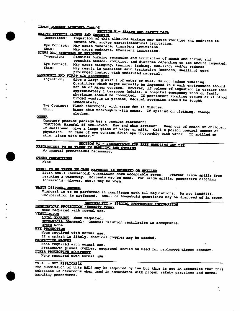
«a«™ «-««Hun TiTflnT«* fiffllt'l H^LTH n*** lmm ^ r££™ Y * ""ffl! «■» ™"TT HUTU
Ingestion«: lotion of thiS ,lkaXia. ^^ uy cause vomiti an<J ^^ to severe oral and/or gastrointestinal irritation »»aerate to
Eye Contact: May cause moderate, transient irritation. «.,J1. L **** caus« moderate, transient irritation. SIGNS WD SYMPTOMS or Btpn.<m»1
Ingestion: *»••""• burning sensation and irritation of mouth and throat and Eve Conta^. £!"** *
Musea: v°»"ing, and diarrhea depending on the amount ingested Eye contact: May cause stinging, tearing, itching, swelling, and/or rednew ingeSted- Skin. May result m transient skin irritation (redness, swelling) upon
««^^«^ . prolonged contact with undiluted material. * P EMERGENCY AMD FTHS* ITD HMPmm»S
Ingestion: Give a large glassful of water or milk, do not induce vomiting. Quantities which might normally be ingested in a work environment should not be of ma3or concern. However, if volume of ing.st!on"^SSter San approximately 1 teaspoon (adult), a hospital emergency roomolfamiV tSae=rvLf?OUld * consultÜ " P«sistent vomiting SSt?o?S blood tinged vomitus is present, medical attention should be sought immediately. *
Eye Contact: Flush thoroughly with water for 15 minutes
Skin: 5otheskin th°IOnghly with "**•«• " «Pill«! on clothing, change HER Consumer product package has a caution statement: »CAUTION: Harmful if swallowed. Eye and skin irritant. Keep out of reach of children If swallowed, give a large glass of water or milk. Call a poison control center or
stiTri'nse w^watel^ «"*'<*•"«•> ^ thoroughly wit? water?^!^^
No unusual precautions necessary.
QTffi* PMCMBOaB None
Flush small (household) o£an™iM dSwTa^cepTable sewer. Prevent large spills from
WAST« DTSPQSAI. MHMP
Disposal is to be performed in compliance with all regulations. Do not landfill Incineration is preferred. Small or household quantifies may be disposeToTinsewer.
—«-. ~—~ IE™ ^»T™ FRPTirTTON TltnpwTg None required with normal use.
VgNTILXTIQM LOCAL EXHAiTST None required. MECHANICAL, (SttnggiH General dilution ventilation is acceptable. OTHER None
EYE PROTECTIOW None required with normal use. If a splash is likely, chemical goggles may be needed.
PROTECTIVE CLOVE«. None required with normal use.
at£^!SSi£r^n£Sr''neopreM) should *-used for proion^d «*™ «~*. None required with normal use.
•N.A. - NOT APPLICABLE The submission of this MSDS may be required by law but this is not an assertion that this substance is hazardous when used in accordance with proper safety practices and normal handling procedures.