Embed Size (px)
Citation preview

Container Refrigeration
OPERATIONS AND SERVICE MANUAL
For
69NT40-561-001 to 199Container Refrigeration Units
T-340 Rev E

OPERATIONS AND SERVICE MANUAL
For
69NT40-561-001 to 199
© 2017 Carrier Corporation ● Printed in USA April 2017


i T-340
TABLE OF CONTENTS
PARAGRAPH NUMBER PAGE
SAFETY SUMMARY . . . . . . . . . . . . . . . . . . . . . . . . . . . . . . . . . . . . . . . . . . . . . . . . . . . . . . . . . . . . . . . . . . . 1–1
1.1 GENERAL SAFETY NOTICES . . . . . . . . . . . . . . . . . . . . . . . . . . . . . . . . . . . . . . . . . . . . . . . . . . 1–1
1.2 FIRST AID . . . . . . . . . . . . . . . . . . . . . . . . . . . . . . . . . . . . . . . . . . . . . . . . . . . . . . . . . . . . . . . . . . 1–1
1.3 OPERATING PRECAUTIONS . . . . . . . . . . . . . . . . . . . . . . . . . . . . . . . . . . . . . . . . . . . . . . . . . . . 1–1
1.4 MAINTENANCE PRECAUTIONS . . . . . . . . . . . . . . . . . . . . . . . . . . . . . . . . . . . . . . . . . . . . . . . . 1–1
1.5 SPECIFIC HAZARD STATEMENTS . . . . . . . . . . . . . . . . . . . . . . . . . . . . . . . . . . . . . . . . . . . . . . 1–1
INTRODUCTION . . . . . . . . . . . . . . . . . . . . . . . . . . . . . . . . . . . . . . . . . . . . . . . . . . . . . . . . . . . . . . . . . . . . . . 2–1
2.1 INTRODUCTION . . . . . . . . . . . . . . . . . . . . . . . . . . . . . . . . . . . . . . . . . . . . . . . . . . . . . . . . . . . . . 2–1
2.2 CONFIGURATION IDENTIFICATION . . . . . . . . . . . . . . . . . . . . . . . . . . . . . . . . . . . . . . . . . . . . . 2–1
2.3 FEATURE DESCRIPTIONS . . . . . . . . . . . . . . . . . . . . . . . . . . . . . . . . . . . . . . . . . . . . . . . . . . . . . 2–1
2.3.1 Control Box . . . . . . . . . . . . . . . . . . . . . . . . . . . . . . . . . . . . . . . . . . . . . . . . . . . . . . . . . . . . . 2–1
2.3.2 Temperature Readout . . . . . . . . . . . . . . . . . . . . . . . . . . . . . . . . . . . . . . . . . . . . . . . . . . . . . 2–1
2.3.3 Pressure Readout . . . . . . . . . . . . . . . . . . . . . . . . . . . . . . . . . . . . . . . . . . . . . . . . . . . . . . . . 2–1
2.3.4 Compressor . . . . . . . . . . . . . . . . . . . . . . . . . . . . . . . . . . . . . . . . . . . . . . . . . . . . . . . . . . . . . 2–1
2.3.5 Condenser Coil . . . . . . . . . . . . . . . . . . . . . . . . . . . . . . . . . . . . . . . . . . . . . . . . . . . . . . . . . . 2–1
2.3.6 Evaporator . . . . . . . . . . . . . . . . . . . . . . . . . . . . . . . . . . . . . . . . . . . . . . . . . . . . . . . . . . . . . . 2–1
2.3.7 Evaporator Fan Operation . . . . . . . . . . . . . . . . . . . . . . . . . . . . . . . . . . . . . . . . . . . . . . . . . . 2–1
2.3.8 Plate Set . . . . . . . . . . . . . . . . . . . . . . . . . . . . . . . . . . . . . . . . . . . . . . . . . . . . . . . . . . . . . . . 2–1
2.4 OPTION DESCRIPTIONS . . . . . . . . . . . . . . . . . . . . . . . . . . . . . . . . . . . . . . . . . . . . . . . . . . . . . . 2–1
2.4.1 Battery . . . . . . . . . . . . . . . . . . . . . . . . . . . . . . . . . . . . . . . . . . . . . . . . . . . . . . . . . . . . . . . . . 2–2
2.4.2 Dehumidification . . . . . . . . . . . . . . . . . . . . . . . . . . . . . . . . . . . . . . . . . . . . . . . . . . . . . . . . . 2–2
2.4.3 USDA . . . . . . . . . . . . . . . . . . . . . . . . . . . . . . . . . . . . . . . . . . . . . . . . . . . . . . . . . . . . . . . . . . 2–2
2.4.4 Interrogator . . . . . . . . . . . . . . . . . . . . . . . . . . . . . . . . . . . . . . . . . . . . . . . . . . . . . . . . . . . . . 2–2
2.4.5 Remote Monitoring . . . . . . . . . . . . . . . . . . . . . . . . . . . . . . . . . . . . . . . . . . . . . . . . . . . . . . . . 2–2
2.4.6 Quest - CCPC . . . . . . . . . . . . . . . . . . . . . . . . . . . . . . . . . . . . . . . . . . . . . . . . . . . . . . . . . . . 2–2
2.4.7 Communications Interface Module . . . . . . . . . . . . . . . . . . . . . . . . . . . . . . . . . . . . . . . . . . . 2–2
2.4.8 Autotransformer . . . . . . . . . . . . . . . . . . . . . . . . . . . . . . . . . . . . . . . . . . . . . . . . . . . . . . . . . . 2–2
2.4.9 Temperature Recorder . . . . . . . . . . . . . . . . . . . . . . . . . . . . . . . . . . . . . . . . . . . . . . . . . . . . . 2–2
2.4.10 Gutters . . . . . . . . . . . . . . . . . . . . . . . . . . . . . . . . . . . . . . . . . . . . . . . . . . . . . . . . . . . . . . . . . 2–2
2.4.11 Handles . . . . . . . . . . . . . . . . . . . . . . . . . . . . . . . . . . . . . . . . . . . . . . . . . . . . . . . . . . . . . . . . 2–2
2.4.12 Thermometer Port . . . . . . . . . . . . . . . . . . . . . . . . . . . . . . . . . . . . . . . . . . . . . . . . . . . . . . . . 2–2
2.4.13 Water Cooling . . . . . . . . . . . . . . . . . . . . . . . . . . . . . . . . . . . . . . . . . . . . . . . . . . . . . . . . . . . 2–2
2.4.14 Back Panels . . . . . . . . . . . . . . . . . . . . . . . . . . . . . . . . . . . . . . . . . . . . . . . . . . . . . . . . . . . . . 2–3
2.4.15 460 Volt Cable . . . . . . . . . . . . . . . . . . . . . . . . . . . . . . . . . . . . . . . . . . . . . . . . . . . . . . . . . . . 2–3
2.4.16 230 Volt Cable . . . . . . . . . . . . . . . . . . . . . . . . . . . . . . . . . . . . . . . . . . . . . . . . . . . . . . . . . . . 2–3
2.4.17 Cable Restraint . . . . . . . . . . . . . . . . . . . . . . . . . . . . . . . . . . . . . . . . . . . . . . . . . . . . . . . . . . 2–3
2.4.18 Upper Air (Fresh Air Make Up) . . . . . . . . . . . . . . . . . . . . . . . . . . . . . . . . . . . . . . . . . . . . . . 2–3
2.4.19 Lower Air (Fresh Air Make Up) . . . . . . . . . . . . . . . . . . . . . . . . . . . . . . . . . . . . . . . . . . . . . . 2–3
2.4.20 Labels . . . . . . . . . . . . . . . . . . . . . . . . . . . . . . . . . . . . . . . . . . . . . . . . . . . . . . . . . . . . . . . . . 2–3
2.4.21 Controller . . . . . . . . . . . . . . . . . . . . . . . . . . . . . . . . . . . . . . . . . . . . . . . . . . . . . . . . . . . . . . . 2–3
2.4.22 Condenser Grille . . . . . . . . . . . . . . . . . . . . . . . . . . . . . . . . . . . . . . . . . . . . . . . . . . . . . . . . . 2–3
2.4.23 Emergency Bypass . . . . . . . . . . . . . . . . . . . . . . . . . . . . . . . . . . . . . . . . . . . . . . . . . . . . . . . 2–3
2.4.24 eAutoFresh . . . . . . . . . . . . . . . . . . . . . . . . . . . . . . . . . . . . . . . . . . . . . . . . . . . . . . . . . . . . . 2–3

T-340 ii
DESCRIPTION . . . . . . . . . . . . . . . . . . . . . . . . . . . . . . . . . . . . . . . . . . . . . . . . . . . . . . . . . . . . . . . . . . . . . . . . 3–1
3.1 GENERAL DESCRIPTION . . . . . . . . . . . . . . . . . . . . . . . . . . . . . . . . . . . . . . . . . . . . . . . . . . . . . . 3–1
3.1.1 Refrigeration Unit - Front Section . . . . . . . . . . . . . . . . . . . . . . . . . . . . . . . . . . . . . . . . . . . . . 3–1
3.1.2 Fresh Air Makeup Vent . . . . . . . . . . . . . . . . . . . . . . . . . . . . . . . . . . . . . . . . . . . . . . . . . . . . . 3–1
3.1.3 Evaporator Section . . . . . . . . . . . . . . . . . . . . . . . . . . . . . . . . . . . . . . . . . . . . . . . . . . . . . . . . 3–2
3.1.4 Compressor Section . . . . . . . . . . . . . . . . . . . . . . . . . . . . . . . . . . . . . . . . . . . . . . . . . . . . . . . 3–3
3.1.5 Air-Cooled Condenser Section . . . . . . . . . . . . . . . . . . . . . . . . . . . . . . . . . . . . . . . . . . . . . . . 3–4
3.1.6 Water-Cooled Condenser Section . . . . . . . . . . . . . . . . . . . . . . . . . . . . . . . . . . . . . . . . . . . . 3–5
3.1.7 Control Box Section . . . . . . . . . . . . . . . . . . . . . . . . . . . . . . . . . . . . . . . . . . . . . . . . . . . . . . . 3–6
3.1.8 Communications Interface Module . . . . . . . . . . . . . . . . . . . . . . . . . . . . . . . . . . . . . . . . . . . . 3–6
3.2 REFRIGERATION SYSTEM DATA . . . . . . . . . . . . . . . . . . . . . . . . . . . . . . . . . . . . . . . . . . . . . . . 3–7
3.3 ELECTRICAL DATA . . . . . . . . . . . . . . . . . . . . . . . . . . . . . . . . . . . . . . . . . . . . . . . . . . . . . . . . . . . 3–8
3.4 SAFETY AND PROTECTIVE DEVICES . . . . . . . . . . . . . . . . . . . . . . . . . . . . . . . . . . . . . . . . . . . . 3–9
3.5 REFRIGERATION CIRCUIT . . . . . . . . . . . . . . . . . . . . . . . . . . . . . . . . . . . . . . . . . . . . . . . . . . . . 3–10
3.5.1 Standard Operation . . . . . . . . . . . . . . . . . . . . . . . . . . . . . . . . . . . . . . . . . . . . . . . . . . . . . . . 3–10
3.5.2 Economized Operation . . . . . . . . . . . . . . . . . . . . . . . . . . . . . . . . . . . . . . . . . . . . . . . . . . . . 3–10
3.5.3 Electronic Expansion Valve . . . . . . . . . . . . . . . . . . . . . . . . . . . . . . . . . . . . . . . . . . . . . . . . 3–10
MICROPROCESSOR . . . . . . . . . . . . . . . . . . . . . . . . . . . . . . . . . . . . . . . . . . . . . . . . . . . . . . . . . . . . . . . . . . . 4–1
4.1 TEMPERATURE CONTROL MICROPROCESSOR SYSTEM . . . . . . . . . . . . . . . . . . . . . . . . . . . 4–1
4.1.1 Keypad . . . . . . . . . . . . . . . . . . . . . . . . . . . . . . . . . . . . . . . . . . . . . . . . . . . . . . . . . . . . . . . . . 4–2
4.1.2 Display Module . . . . . . . . . . . . . . . . . . . . . . . . . . . . . . . . . . . . . . . . . . . . . . . . . . . . . . . . . . . 4–2
4.1.3 Controller . . . . . . . . . . . . . . . . . . . . . . . . . . . . . . . . . . . . . . . . . . . . . . . . . . . . . . . . . . . . . . . 4–3
4.2 CONTROLLER SOFTWARE . . . . . . . . . . . . . . . . . . . . . . . . . . . . . . . . . . . . . . . . . . . . . . . . . . . . 4–3
4.2.1 Configuration Software (CnF Variables) . . . . . . . . . . . . . . . . . . . . . . . . . . . . . . . . . . . . . . . . 4–4
4.2.2 Operational Software (Cd Function Codes) . . . . . . . . . . . . . . . . . . . . . . . . . . . . . . . . . . . . . 4–4
4.3 MODES OF OPERATION . . . . . . . . . . . . . . . . . . . . . . . . . . . . . . . . . . . . . . . . . . . . . . . . . . . . . . . 4–4
4.3.1 Start up - Compressor Phase Sequence . . . . . . . . . . . . . . . . . . . . . . . . . . . . . . . . . . . . . . . 4–5
4.3.2 Start up - Compressor Bump Start . . . . . . . . . . . . . . . . . . . . . . . . . . . . . . . . . . . . . . . . . . . . 4–5
4.3.3 Perishable Mode Temperature Control . . . . . . . . . . . . . . . . . . . . . . . . . . . . . . . . . . . . . . . . . 4–5
4.3.4 Perishable Pulldown . . . . . . . . . . . . . . . . . . . . . . . . . . . . . . . . . . . . . . . . . . . . . . . . . . . . . . . 4–5
4.3.5 Perishable Steady State . . . . . . . . . . . . . . . . . . . . . . . . . . . . . . . . . . . . . . . . . . . . . . . . . . . . 4–5
4.3.6 Perishable Idle, Air Circulation . . . . . . . . . . . . . . . . . . . . . . . . . . . . . . . . . . . . . . . . . . . . . . . 4–5
4.3.7 Perishable Heating . . . . . . . . . . . . . . . . . . . . . . . . . . . . . . . . . . . . . . . . . . . . . . . . . . . . . . . . 4–5
4.3.8 Perishable Dehumidification . . . . . . . . . . . . . . . . . . . . . . . . . . . . . . . . . . . . . . . . . . . . . . . . . 4–6
4.3.9 Perishable Dehumidification - Bulb Mode . . . . . . . . . . . . . . . . . . . . . . . . . . . . . . . . . . . . . . . 4–7
4.3.10 Perishable Economy . . . . . . . . . . . . . . . . . . . . . . . . . . . . . . . . . . . . . . . . . . . . . . . . . . . . . . . 4–7
4.3.11 Perishable Mode Cooling - Sequence of Operation . . . . . . . . . . . . . . . . . . . . . . . . . . . . . . . 4–7
4.3.12 Perishable Mode Heating - Sequence of Operation . . . . . . . . . . . . . . . . . . . . . . . . . . . . . . . 4–8
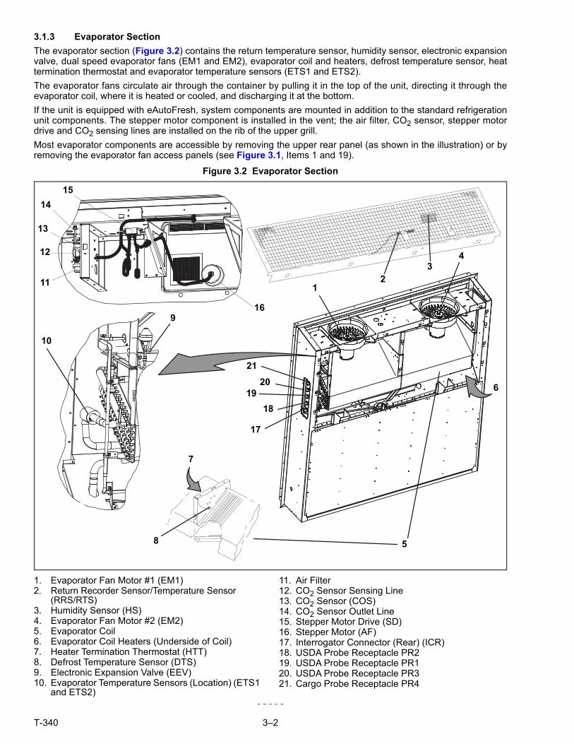
4.3.13 Perishable Mode - Trim Heat . . . . . . . . . . . . . . . . . . . . . . . . . . . . . . . . . . . . . . . . . . . . . . . . 4–9
4.3.14 Frozen Mode - Temperature Control . . . . . . . . . . . . . . . . . . . . . . . . . . . . . . . . . . . . . . . . . . 4–9
4.3.15 Frozen Steady State . . . . . . . . . . . . . . . . . . . . . . . . . . . . . . . . . . . . . . . . . . . . . . . . . . . . . . . 4–9
4.3.16 Frozen Idle Mode . . . . . . . . . . . . . . . . . . . . . . . . . . . . . . . . . . . . . . . . . . . . . . . . . . . . . . . . . 4–9
4.3.17 Frozen “Heat” Mode . . . . . . . . . . . . . . . . . . . . . . . . . . . . . . . . . . . . . . . . . . . . . . . . . . . . . . 4–10
4.3.18 Frozen Economy Mode . . . . . . . . . . . . . . . . . . . . . . . . . . . . . . . . . . . . . . . . . . . . . . . . . . . . 4–10
4.3.19 Frozen Mode Cooling - Sequence of Operation . . . . . . . . . . . . . . . . . . . . . . . . . . . . . . . . . 4–10
4.3.20 Defrost . . . . . . . . . . . . . . . . . . . . . . . . . . . . . . . . . . . . . . . . . . . . . . . . . . . . . . . . . . . . . . . . 4–11
4.3.21 Automatic Defrost . . . . . . . . . . . . . . . . . . . . . . . . . . . . . . . . . . . . . . . . . . . . . . . . . . . . . . . . 4–12
4.3.22 Defrost Initiation . . . . . . . . . . . . . . . . . . . . . . . . . . . . . . . . . . . . . . . . . . . . . . . . . . . . . . . . . 4–12

iii T-340
4.3.23 Defrost Interval . . . . . . . . . . . . . . . . . . . . . . . . . . . . . . . . . . . . . . . . . . . . . . . . . . . . . . . . . . 4–13
4.3.24 Defrost Related Settings . . . . . . . . . . . . . . . . . . . . . . . . . . . . . . . . . . . . . . . . . . . . . . . . . . 4–13
4.4 PROTECTION MODES OF OPERATION . . . . . . . . . . . . . . . . . . . . . . . . . . . . . . . . . . . . . . . . . 4–14
4.4.1 Evaporator Fan Operation . . . . . . . . . . . . . . . . . . . . . . . . . . . . . . . . . . . . . . . . . . . . . . . . . 4–14
4.4.2 Failure Action . . . . . . . . . . . . . . . . . . . . . . . . . . . . . . . . . . . . . . . . . . . . . . . . . . . . . . . . . . . 4–14
4.4.3 Generator Protection . . . . . . . . . . . . . . . . . . . . . . . . . . . . . . . . . . . . . . . . . . . . . . . . . . . . . 4–14
4.4.4 Compressor High Temperature, Low Pressure Protection . . . . . . . . . . . . . . . . . . . . . . . . 4–14
4.4.5 Perishable Mode - System Pressure Regulation . . . . . . . . . . . . . . . . . . . . . . . . . . . . . . . . 4–14
4.4.6 Condenser Fan Override . . . . . . . . . . . . . . . . . . . . . . . . . . . . . . . . . . . . . . . . . . . . . . . . . . 4–15
4.5 QUEST - CCPC . . . . . . . . . . . . . . . . . . . . . . . . . . . . . . . . . . . . . . . . . . . . . . . . . . . . . . . . . . . . . 4–15
4.6 CONTROLLER ALARMS . . . . . . . . . . . . . . . . . . . . . . . . . . . . . . . . . . . . . . . . . . . . . . . . . . . . . . 4–15
4.7 PRE-TRIP DIAGNOSTICS . . . . . . . . . . . . . . . . . . . . . . . . . . . . . . . . . . . . . . . . . . . . . . . . . . . . . 4–16
4.8 DATACORDER . . . . . . . . . . . . . . . . . . . . . . . . . . . . . . . . . . . . . . . . . . . . . . . . . . . . . . . . . . . . . 4–16
4.8.1 Description . . . . . . . . . . . . . . . . . . . . . . . . . . . . . . . . . . . . . . . . . . . . . . . . . . . . . . . . . . . . . 4–16
4.8.2 DataCORDER Software . . . . . . . . . . . . . . . . . . . . . . . . . . . . . . . . . . . . . . . . . . . . . . . . . . . 4–17
4.8.3 Sensor Configuration (dCF02) . . . . . . . . . . . . . . . . . . . . . . . . . . . . . . . . . . . . . . . . . . . . . . 4–17
4.8.4 Logging Interval (dCF03) . . . . . . . . . . . . . . . . . . . . . . . . . . . . . . . . . . . . . . . . . . . . . . . . . . 4–18
4.8.5 Thermistor Format (dCF04) . . . . . . . . . . . . . . . . . . . . . . . . . . . . . . . . . . . . . . . . . . . . . . . . 4–18
4.8.6 Sampling Type (dCF05 & dCF06) . . . . . . . . . . . . . . . . . . . . . . . . . . . . . . . . . . . . . . . . . . . 4–20
4.8.7 Alarm Configuration (dCF07 - dCF10) . . . . . . . . . . . . . . . . . . . . . . . . . . . . . . . . . . . . . . . . 4–20
4.8.8 DataCORDER Power Up . . . . . . . . . . . . . . . . . . . . . . . . . . . . . . . . . . . . . . . . . . . . . . . . . . 4–20
4.8.9 Pre-trip Data Recording . . . . . . . . . . . . . . . . . . . . . . . . . . . . . . . . . . . . . . . . . . . . . . . . . . . 4–21
4.8.10 DataCORDER Communications . . . . . . . . . . . . . . . . . . . . . . . . . . . . . . . . . . . . . . . . . . . . 4–21
4.8.11 USDA Cold Treatment . . . . . . . . . . . . . . . . . . . . . . . . . . . . . . . . . . . . . . . . . . . . . . . . . . . . 4–22
4.8.12 USDA Cold Treatment Procedure . . . . . . . . . . . . . . . . . . . . . . . . . . . . . . . . . . . . . . . . . . . 4–22
4.8.13 DataCORDER Alarms . . . . . . . . . . . . . . . . . . . . . . . . . . . . . . . . . . . . . . . . . . . . . . . . . . . . 4–23
4.8.14 ISO Trip Header . . . . . . . . . . . . . . . . . . . . . . . . . . . . . . . . . . . . . . . . . . . . . . . . . . . . . . . . . 4–23
4.9 CONTROLLER CONFIGURATION VARIABLES . . . . . . . . . . . . . . . . . . . . . . . . . . . . . . . . . . . . 4–24
4.10 CONTROLLER FUNCTION CODES . . . . . . . . . . . . . . . . . . . . . . . . . . . . . . . . . . . . . . . . . . . . . 4–25
4.11 CONTROLLER ALARM INDICATIONS . . . . . . . . . . . . . . . . . . . . . . . . . . . . . . . . . . . . . . . . . . . 4–34
4.12 CONTROLLER PRE- TRIP TEST CODES . . . . . . . . . . . . . . . . . . . . . . . . . . . . . . . . . . . . . . . . 4–43
OPERATION . . . . . . . . . . . . . . . . . . . . . . . . . . . . . . . . . . . . . . . . . . . . . . . . . . . . . . . . . . . . . . . . . . . . . . . . . 5–1
5.1 INSPECTION (BEFORE LOADING) . . . . . . . . . . . . . . . . . . . . . . . . . . . . . . . . . . . . . . . . . . . . . . 5–1
5.2 CONNECT POWER . . . . . . . . . . . . . . . . . . . . . . . . . . . . . . . . . . . . . . . . . . . . . . . . . . . . . . . . . . . 5–1
5.2.1 Connection To 380/460 VAC Power . . . . . . . . . . . . . . . . . . . . . . . . . . . . . . . . . . . . . . . . . . 5–1
5.2.2 Connection To 190/230 VAC Power . . . . . . . . . . . . . . . . . . . . . . . . . . . . . . . . . . . . . . . . . . 5–1
5.3 ADJUST FRESH AIR MAKEUP VENT . . . . . . . . . . . . . . . . . . . . . . . . . . . . . . . . . . . . . . . . . . . . 5–2
5.3.1 Upper Fresh Air Makeup Vent . . . . . . . . . . . . . . . . . . . . . . . . . . . . . . . . . . . . . . . . . . . . . . . 5–2
5.3.2 Lower Fresh Air Makeup Vent . . . . . . . . . . . . . . . . . . . . . . . . . . . . . . . . . . . . . . . . . . . . . . . 5–3
5.3.3 Vent Position Sensor . . . . . . . . . . . . . . . . . . . . . . . . . . . . . . . . . . . . . . . . . . . . . . . . . . . . . . 5–4
5.4 EAUTOFRESH OPERATION . . . . . . . . . . . . . . . . . . . . . . . . . . . . . . . . . . . . . . . . . . . . . . . . . . . . 5–4
5.4.1 eAutoFresh Pre-Trip Inspection . . . . . . . . . . . . . . . . . . . . . . . . . . . . . . . . . . . . . . . . . . . . . . 5–4
5.4.2 eAutoFresh Start-Up Procedure . . . . . . . . . . . . . . . . . . . . . . . . . . . . . . . . . . . . . . . . . . . . . 5–5
5.4.3 eAutoFresh Modes of Operation . . . . . . . . . . . . . . . . . . . . . . . . . . . . . . . . . . . . . . . . . . . . . 5–5
5.5 CONNECT WATER-COOLED CONDENSER . . . . . . . . . . . . . . . . . . . . . . . . . . . . . . . . . . . . . . . 5–6
5.5.1 Water-Cooled Condenser with Water Pressure Switch . . . . . . . . . . . . . . . . . . . . . . . . . . . . 5–6
5.5.2 Water-Cooled Condenser with Condenser Fan Switch . . . . . . . . . . . . . . . . . . . . . . . . . . . . 5–6
5.6 CONNECT REMOTE MONITORING RECEPTACLE . . . . . . . . . . . . . . . . . . . . . . . . . . . . . . . . . 5–7

T-340 iv
5.7 STARTING AND STOPPING INSTRUCTIONS . . . . . . . . . . . . . . . . . . . . . . . . . . . . . . . . . . . . . . 5–7
5.7.1 Starting the Unit . . . . . . . . . . . . . . . . . . . . . . . . . . . . . . . . . . . . . . . . . . . . . . . . . . . . . . . . . . 5–7
5.7.2 Stopping the Unit . . . . . . . . . . . . . . . . . . . . . . . . . . . . . . . . . . . . . . . . . . . . . . . . . . . . . . . . . 5–7
5.8 START-UP INSPECTION . . . . . . . . . . . . . . . . . . . . . . . . . . . . . . . . . . . . . . . . . . . . . . . . . . . . . . . 5–7
5.8.1 Physical Inspection . . . . . . . . . . . . . . . . . . . . . . . . . . . . . . . . . . . . . . . . . . . . . . . . . . . . . . . . 5–7
5.8.2 Check Controller Function Codes . . . . . . . . . . . . . . . . . . . . . . . . . . . . . . . . . . . . . . . . . . . . . 5–7
5.8.3 Start Temperature Recorder . . . . . . . . . . . . . . . . . . . . . . . . . . . . . . . . . . . . . . . . . . . . . . . . . 5–8
5.8.4 Complete Inspection . . . . . . . . . . . . . . . . . . . . . . . . . . . . . . . . . . . . . . . . . . . . . . . . . . . . . . . 5–8
5.9 PRE-TRIP DIAGNOSIS . . . . . . . . . . . . . . . . . . . . . . . . . . . . . . . . . . . . . . . . . . . . . . . . . . . . . . . . . 5–8
5.10 PROBE DIAGNOSTICS . . . . . . . . . . . . . . . . . . . . . . . . . . . . . . . . . . . . . . . . . . . . . . . . . . . . . . . 5–10
5.11 EMERGENCY BYPASS OPERATION . . . . . . . . . . . . . . . . . . . . . . . . . . . . . . . . . . . . . . . . . . . . 5–10
TROUBLESHOOTING . . . . . . . . . . . . . . . . . . . . . . . . . . . . . . . . . . . . . . . . . . . . . . . . . . . . . . . . . . . . . . . . . . 6–1
6.1 UNIT WILL NOT START OR STARTS THEN STOPS . . . . . . . . . . . . . . . . . . . . . . . . . . . . . . . . . 6–1
6.2 UNIT OPERATES LONG OR CONTINUOUSLY IN COOLING . . . . . . . . . . . . . . . . . . . . . . . . . . 6–1
6.3 UNIT RUNS BUT HAS INSUFFICIENT COOLING . . . . . . . . . . . . . . . . . . . . . . . . . . . . . . . . . . . . 6–2
6.4 UNIT WILL NOT HEAT OR HAS INSUFFICIENT HEATING . . . . . . . . . . . . . . . . . . . . . . . . . . . . 6–2
6.5 UNIT WILL NOT TERMINATE HEATING . . . . . . . . . . . . . . . . . . . . . . . . . . . . . . . . . . . . . . . . . . . 6–2
6.6 UNIT WILL NOT DEFROST PROPERLY . . . . . . . . . . . . . . . . . . . . . . . . . . . . . . . . . . . . . . . . . . . 6–2
6.7 ABNORMAL PRESSURES . . . . . . . . . . . . . . . . . . . . . . . . . . . . . . . . . . . . . . . . . . . . . . . . . . . . . . 6–3
6.8 ABNORMAL NOISE OR VIBRATIONS . . . . . . . . . . . . . . . . . . . . . . . . . . . . . . . . . . . . . . . . . . . . . 6–3
6.9 MICROPROCESSOR MALFUNCTION . . . . . . . . . . . . . . . . . . . . . . . . . . . . . . . . . . . . . . . . . . . . 6–4
6.10 NO EVAPORATOR AIR FLOW OR RESTRICTED AIR FLOW . . . . . . . . . . . . . . . . . . . . . . . . . . 6–4
6.11 EAUTOFRESH NOT OPERATING . . . . . . . . . . . . . . . . . . . . . . . . . . . . . . . . . . . . . . . . . . . . . . . . 6–4
6.12 ELECTRONIC EXPANSION VALVE MALFUNCTION . . . . . . . . . . . . . . . . . . . . . . . . . . . . . . . . . 6–4
6.13 AUTOTRANSFORMER MALFUNCTION . . . . . . . . . . . . . . . . . . . . . . . . . . . . . . . . . . . . . . . . . . . 6–5
6.14 WATER−COOLED CONDENSER OR WATER PRESSURE SWITCH . . . . . . . . . . . . . . . . . . . . 6–5
6.15 COMPRESSOR OPERATING IN REVERSE . . . . . . . . . . . . . . . . . . . . . . . . . . . . . . . . . . . . . . . . 6–5
6.16 ABNORMAL TEMPERATURES . . . . . . . . . . . . . . . . . . . . . . . . . . . . . . . . . . . . . . . . . . . . . . . . . . 6–6
6.17 ABNORMAL CURRENTS . . . . . . . . . . . . . . . . . . . . . . . . . . . . . . . . . . . . . . . . . . . . . . . . . . . . . . . 6–6
SERVICE . . . . . . . . . . . . . . . . . . . . . . . . . . . . . . . . . . . . . . . . . . . . . . . . . . . . . . . . . . . . . . . . . . . . . . . . . . . . . 7–1
7.1 SECTION LAYOUT . . . . . . . . . . . . . . . . . . . . . . . . . . . . . . . . . . . . . . . . . . . . . . . . . . . . . . . . . . . . 7–1
7.2 MANIFOLD GAUGE SET . . . . . . . . . . . . . . . . . . . . . . . . . . . . . . . . . . . . . . . . . . . . . . . . . . . . . . . 7–1
7.3 SERVICE CONNECTIONS . . . . . . . . . . . . . . . . . . . . . . . . . . . . . . . . . . . . . . . . . . . . . . . . . . . . . . 7–2
7.4 PUMP DOWN THE UNIT . . . . . . . . . . . . . . . . . . . . . . . . . . . . . . . . . . . . . . . . . . . . . . . . . . . . . . . 7–3
7.5 REFRIGERANT LEAK CHECKING . . . . . . . . . . . . . . . . . . . . . . . . . . . . . . . . . . . . . . . . . . . . . . . 7–4
7.6 EVACUATION AND DEHYDRATION . . . . . . . . . . . . . . . . . . . . . . . . . . . . . . . . . . . . . . . . . . . . . . 7–4
7.6.1 General . . . . . . . . . . . . . . . . . . . . . . . . . . . . . . . . . . . . . . . . . . . . . . . . . . . . . . . . . . . . . . . . 7–4
7.6.2 Preparation . . . . . . . . . . . . . . . . . . . . . . . . . . . . . . . . . . . . . . . . . . . . . . . . . . . . . . . . . . . . . . 7–4
7.6.3 Complete System . . . . . . . . . . . . . . . . . . . . . . . . . . . . . . . . . . . . . . . . . . . . . . . . . . . . . . . . . 7–5
7.6.4 Partial System . . . . . . . . . . . . . . . . . . . . . . . . . . . . . . . . . . . . . . . . . . . . . . . . . . . . . . . . . . . . 7–6
7.7 REFRIGERANT CHARGE . . . . . . . . . . . . . . . . . . . . . . . . . . . . . . . . . . . . . . . . . . . . . . . . . . . . . . 7–6
7.7.1 Checking the Refrigerant Charge . . . . . . . . . . . . . . . . . . . . . . . . . . . . . . . . . . . . . . . . . . . . . 7–6
7.7.2 Adding Refrigerant to System (Full Charge) . . . . . . . . . . . . . . . . . . . . . . . . . . . . . . . . . . . . . 7–6
7.7.3 Adding Refrigerant to System (Partial Charge) . . . . . . . . . . . . . . . . . . . . . . . . . . . . . . . . . . . 7–6
7.8 COMPRESSOR . . . . . . . . . . . . . . . . . . . . . . . . . . . . . . . . . . . . . . . . . . . . . . . . . . . . . . . . . . . . . . 7–7
7.8.1 Removal and Replacement of Compressor . . . . . . . . . . . . . . . . . . . . . . . . . . . . . . . . . . . . . 7–7
7.9 HIGH PRESSURE SWITCH . . . . . . . . . . . . . . . . . . . . . . . . . . . . . . . . . . . . . . . . . . . . . . . . . . . . . 7–9
7.9.1 Checking High Pressure Switch . . . . . . . . . . . . . . . . . . . . . . . . . . . . . . . . . . . . . . . . . . . . . . 7–9
7.9.2 Replacing High Pressure Switch . . . . . . . . . . . . . . . . . . . . . . . . . . . . . . . . . . . . . . . . . . . . . . 7–9

v T-340
7.10 CONDENSER COIL . . . . . . . . . . . . . . . . . . . . . . . . . . . . . . . . . . . . . . . . . . . . . . . . . . . . . . . . . . 7–10
7.11 CONDENSER FAN AND MOTOR ASSEMBLY . . . . . . . . . . . . . . . . . . . . . . . . . . . . . . . . . . . . . 7–10
7.12 WATER-COOLED CONDENSER CLEANING . . . . . . . . . . . . . . . . . . . . . . . . . . . . . . . . . . . . . . 7–10
7.13 FILTER DRIER . . . . . . . . . . . . . . . . . . . . . . . . . . . . . . . . . . . . . . . . . . . . . . . . . . . . . . . . . . . . . . 7–13
7.14 EVAPORATOR COIL & HEATER ASSEMBLY . . . . . . . . . . . . . . . . . . . . . . . . . . . . . . . . . . . . . 7–14
7.14.1 Evaporator Coil Replacement . . . . . . . . . . . . . . . . . . . . . . . . . . . . . . . . . . . . . . . . . . . . . . 7–14
7.14.2 Evaporator Heater Replacement . . . . . . . . . . . . . . . . . . . . . . . . . . . . . . . . . . . . . . . . . . . . 7–14
7.15 EVAPORATOR FAN AND MOTOR ASSEMBLY . . . . . . . . . . . . . . . . . . . . . . . . . . . . . . . . . . . . 7–15
7.15.1 Replacing the Evaporator Fan Assembly . . . . . . . . . . . . . . . . . . . . . . . . . . . . . . . . . . . . . . 7–15
7.15.2 Disassemble the Evaporator Fan Assembly . . . . . . . . . . . . . . . . . . . . . . . . . . . . . . . . . . . 7–15
7.15.3 Assemble the Evaporator Fan Assembly . . . . . . . . . . . . . . . . . . . . . . . . . . . . . . . . . . . . . . 7–16
7.16 EVAPORATOR SECTION CLEANING . . . . . . . . . . . . . . . . . . . . . . . . . . . . . . . . . . . . . . . . . . . 7–16
7.17 ELECTRONIC EXPANSION VALVE . . . . . . . . . . . . . . . . . . . . . . . . . . . . . . . . . . . . . . . . . . . . . 7–17
7.17.1 Replacing Electronic Expansion Valve and Screen . . . . . . . . . . . . . . . . . . . . . . . . . . . . . . 7–17
7.18 ECONOMIZER SOLENOID VALVE . . . . . . . . . . . . . . . . . . . . . . . . . . . . . . . . . . . . . . . . . . . . . . 7–18
7.19 ECONOMIZER EXPANSION VALVE . . . . . . . . . . . . . . . . . . . . . . . . . . . . . . . . . . . . . . . . . . . . 7–19
7.19.1 Economizer Expansion Replacement . . . . . . . . . . . . . . . . . . . . . . . . . . . . . . . . . . . . . . . . 7–19
7.20 DIGITAL UNLOADER VALVE . . . . . . . . . . . . . . . . . . . . . . . . . . . . . . . . . . . . . . . . . . . . . . . . . . 7–20
7.21 VALVE OVERRIDE CONTROLS . . . . . . . . . . . . . . . . . . . . . . . . . . . . . . . . . . . . . . . . . . . . . . . . 7–21
7.22 AUTOTRANSFORMER . . . . . . . . . . . . . . . . . . . . . . . . . . . . . . . . . . . . . . . . . . . . . . . . . . . . . . . 7–22
7.23 CONTROLLER . . . . . . . . . . . . . . . . . . . . . . . . . . . . . . . . . . . . . . . . . . . . . . . . . . . . . . . . . . . . . 7–23
7.23.1 Handling Modules . . . . . . . . . . . . . . . . . . . . . . . . . . . . . . . . . . . . . . . . . . . . . . . . . . . . . . . 7–23
7.23.2 Controller Troubleshooting . . . . . . . . . . . . . . . . . . . . . . . . . . . . . . . . . . . . . . . . . . . . . . . . . 7–23
7.23.3 Controller Programming Procedure . . . . . . . . . . . . . . . . . . . . . . . . . . . . . . . . . . . . . . . . . . 7–24
7.23.4 Removing and Installing a Controller . . . . . . . . . . . . . . . . . . . . . . . . . . . . . . . . . . . . . . . . . 7–27
7.23.5 Battery Replacement . . . . . . . . . . . . . . . . . . . . . . . . . . . . . . . . . . . . . . . . . . . . . . . . . . . . . 7–27
7.24 TEMPERATURE SENSOR SERVICE . . . . . . . . . . . . . . . . . . . . . . . . . . . . . . . . . . . . . . . . . . . . 7–28
7.24.1 Sensor Checkout Procedure . . . . . . . . . . . . . . . . . . . . . . . . . . . . . . . . . . . . . . . . . . . . . . . 7–28
7.24.2 Sensor Replacement . . . . . . . . . . . . . . . . . . . . . . . . . . . . . . . . . . . . . . . . . . . . . . . . . . . . . 7–31
7.24.3 Sensors Re-Installation . . . . . . . . . . . . . . . . . . . . . . . . . . . . . . . . . . . . . . . . . . . . . . . . . . . 7–32
7.25 VENT POSITION SENSOR (VPS) . . . . . . . . . . . . . . . . . . . . . . . . . . . . . . . . . . . . . . . . . . . . . . . 7–34
7.26 EAUTOFRESH SERVICE . . . . . . . . . . . . . . . . . . . . . . . . . . . . . . . . . . . . . . . . . . . . . . . . . . . . . 7–35
7.26.1 Servicing the eAutoFresh Air Filter . . . . . . . . . . . . . . . . . . . . . . . . . . . . . . . . . . . . . . . . . . 7–35
7.26.2 Checking eAutoFresh Drive System . . . . . . . . . . . . . . . . . . . . . . . . . . . . . . . . . . . . . . . . . 7–35
7.26.3 Checking the Controller . . . . . . . . . . . . . . . . . . . . . . . . . . . . . . . . . . . . . . . . . . . . . . . . . . . 7–36
7.26.4 Servicing the eAutoFresh Drive System . . . . . . . . . . . . . . . . . . . . . . . . . . . . . . . . . . . . . . 7–37
7.27 ELECTRONIC PARTLOW TEMPERATURE RECORDER . . . . . . . . . . . . . . . . . . . . . . . . . . . . 7–38
7.27.1 Replacing the Recorder . . . . . . . . . . . . . . . . . . . . . . . . . . . . . . . . . . . . . . . . . . . . . . . . . . . 7–39
7.27.2 Recalibrating the Temp Recorder to Zero . . . . . . . . . . . . . . . . . . . . . . . . . . . . . . . . . . . . . 7–40
7.28 MAINTENANCE OF PAINTED SURFACES . . . . . . . . . . . . . . . . . . . . . . . . . . . . . . . . . . . . . . . 7–40
7.29 COMMUNICATIONS INTERFACE MODULE INSTALLATION . . . . . . . . . . . . . . . . . . . . . . . . . 7–40
ELECTRICAL WIRING SCHEMATICS . . . . . . . . . . . . . . . . . . . . . . . . . . . . . . . . . . . . . . . . . . . . . . . . . . . . . 8–1
8.1 INTRODUCTION . . . . . . . . . . . . . . . . . . . . . . . . . . . . . . . . . . . . . . . . . . . . . . . . . . . . . . . . . . . . . 8–1
INDEX . . . . . . . . . . . . . . . . . . . . . . . . . . . . . . . . . . . . . . . . . . . . . . . . . . . . . . . . . . . . . . . . . . . . . . . . . . . . . . . 1–1


T-340 vii
LIST OF ILLUSTRATIONS
FIGURE NUMBER Page
Figure 3.1 Refrigeration Unit - Front Section . . . . . . . . . . . . . . . . . . . . . . . . . . . . . . . . . . . . . . . . . . . . . . . . . . 3–1
Figure 3.2 Evaporator Section . . . . . . . . . . . . . . . . . . . . . . . . . . . . . . . . . . . . . . . . . . . . . . . . . . . . . . . . . . . . . 3–2
Figure 3.3 Compressor Section . . . . . . . . . . . . . . . . . . . . . . . . . . . . . . . . . . . . . . . . . . . . . . . . . . . . . . . . . . . . 3–3
Figure 3.4 Air-Cooled Condenser Section . . . . . . . . . . . . . . . . . . . . . . . . . . . . . . . . . . . . . . . . . . . . . . . . . . . . 3–4
Figure 3.5 Water-Cooled Condenser Section . . . . . . . . . . . . . . . . . . . . . . . . . . . . . . . . . . . . . . . . . . . . . . . . . 3–5
Figure 3.6 Control Box Section . . . . . . . . . . . . . . . . . . . . . . . . . . . . . . . . . . . . . . . . . . . . . . . . . . . . . . . . . . . . 3–6
Figure 3.7 Refrigeration Circuit Schematic - Standard Operation . . . . . . . . . . . . . . . . . . . . . . . . . . . . . . . . . 3–11
Figure 3.8 Refrigeration Circuit Schematic - Economized Operation . . . . . . . . . . . . . . . . . . . . . . . . . . . . . . 3–12
Figure 4.1 Temperature Control System . . . . . . . . . . . . . . . . . . . . . . . . . . . . . . . . . . . . . . . . . . . . . . . . . . . . . 4–1
Figure 4.2 Keypad . . . . . . . . . . . . . . . . . . . . . . . . . . . . . . . . . . . . . . . . . . . . . . . . . . . . . . . . . . . . . . . . . . . . . . 4–2
Figure 4.3 Display Module . . . . . . . . . . . . . . . . . . . . . . . . . . . . . . . . . . . . . . . . . . . . . . . . . . . . . . . . . . . . . . . . 4–3
Figure 4.4 Control Module . . . . . . . . . . . . . . . . . . . . . . . . . . . . . . . . . . . . . . . . . . . . . . . . . . . . . . . . . . . . . . . . 4–4
Figure 4.5 Controller Operation - Perishable Mode . . . . . . . . . . . . . . . . . . . . . . . . . . . . . . . . . . . . . . . . . . . . . 4–6
Figure 4.6 Perishable Mode Cooling . . . . . . . . . . . . . . . . . . . . . . . . . . . . . . . . . . . . . . . . . . . . . . . . . . . . . . . . 4–8
Figure 4.7 Perishable Mode Heating . . . . . . . . . . . . . . . . . . . . . . . . . . . . . . . . . . . . . . . . . . . . . . . . . . . . . . . . 4–9
Figure 4.8 Controller Operation - Frozen Mode . . . . . . . . . . . . . . . . . . . . . . . . . . . . . . . . . . . . . . . . . . . . . . . 4–10
Figure 4.9 Frozen Mode . . . . . . . . . . . . . . . . . . . . . . . . . . . . . . . . . . . . . . . . . . . . . . . . . . . . . . . . . . . . . . . . 4–11
Figure 4.10 Defrost . . . . . . . . . . . . . . . . . . . . . . . . . . . . . . . . . . . . . . . . . . . . . . . . . . . . . . . . . . . . . . . . . . . . 4–13
Figure 4.11 Standard Configuration Download Report . . . . . . . . . . . . . . . . . . . . . . . . . . . . . . . . . . . . . . . . . 4–19
Figure 4.12 DataReader . . . . . . . . . . . . . . . . . . . . . . . . . . . . . . . . . . . . . . . . . . . . . . . . . . . . . . . . . . . . . . . . 4–21
Figure 4.13 Alarm Troubleshooting Sequence . . . . . . . . . . . . . . . . . . . . . . . . . . . . . . . . . . . . . . . . . . . . . . . 4–33
Figure 5.1 Autotransformer . . . . . . . . . . . . . . . . . . . . . . . . . . . . . . . . . . . . . . . . . . . . . . . . . . . . . . . . . . . . . . . 5–2
Figure 5.2 Upper Fresh Air Make Up Flow Chart . . . . . . . . . . . . . . . . . . . . . . . . . . . . . . . . . . . . . . . . . . . . . . 5–3
Figure 5.3 Diagram of Emergency Bypass Connections . . . . . . . . . . . . . . . . . . . . . . . . . . . . . . . . . . . . . . . . 5–11
Figure 7.1 Manifold Gauge Set . . . . . . . . . . . . . . . . . . . . . . . . . . . . . . . . . . . . . . . . . . . . . . . . . . . . . . . . . . . . 7–1
Figure 7.2 R-134a Manifold Gauge/Hose Set . . . . . . . . . . . . . . . . . . . . . . . . . . . . . . . . . . . . . . . . . . . . . . . . . 7–2
Figure 7.3 Service Valve . . . . . . . . . . . . . . . . . . . . . . . . . . . . . . . . . . . . . . . . . . . . . . . . . . . . . . . . . . . . . . . . . 7–3
Figure 7.4 Refrigeration System Service Connections . . . . . . . . . . . . . . . . . . . . . . . . . . . . . . . . . . . . . . . . . . 7–5
Figure 7.5 Compressor Kit . . . . . . . . . . . . . . . . . . . . . . . . . . . . . . . . . . . . . . . . . . . . . . . . . . . . . . . . . . . . . . . . 7–8
Figure 7.6 High Pressure Switch Testing . . . . . . . . . . . . . . . . . . . . . . . . . . . . . . . . . . . . . . . . . . . . . . . . . . . . 7–9
Figure 7.7 Water-Cooled Condenser Cleaning, Forced Circulation . . . . . . . . . . . . . . . . . . . . . . . . . . . . . . . 7–12
Figure 7.8 Water-Cooled Condenser Cleaning - Gravity Circulation . . . . . . . . . . . . . . . . . . . . . . . . . . . . . . . 7–13
Figure 7.9 5+1 Heater Arrangement - Omega Heater . . . . . . . . . . . . . . . . . . . . . . . . . . . . . . . . . . . . . . . . . . 7–15
Figure 7.10 Evaporator Fan Assembly . . . . . . . . . . . . . . . . . . . . . . . . . . . . . . . . . . . . . . . . . . . . . . . . . . . . . 7–16
Figure 7.11 Electronic Expansion Valve . . . . . . . . . . . . . . . . . . . . . . . . . . . . . . . . . . . . . . . . . . . . . . . . . . . . 7–18
Figure 7.12 Coil View of Economizer Solenoid Valve (ESV) . . . . . . . . . . . . . . . . . . . . . . . . . . . . . . . . . . . . . 7–18
Figure 7.13 Economizer Expansion Valve . . . . . . . . . . . . . . . . . . . . . . . . . . . . . . . . . . . . . . . . . . . . . . . . . . . 7–19
Figure 7.14 View of Digital Unloader Valve (DUV) Assembly . . . . . . . . . . . . . . . . . . . . . . . . . . . . . . . . . . . . 7–20
Figure 7.15 Autotransformer . . . . . . . . . . . . . . . . . . . . . . . . . . . . . . . . . . . . . . . . . . . . . . . . . . . . . . . . . . . . . 7–22
Figure 7.16 Controller Section of the Control Box . . . . . . . . . . . . . . . . . . . . . . . . . . . . . . . . . . . . . . . . . . . . . 7–24
Figure 7.17 Sensor Types . . . . . . . . . . . . . . . . . . . . . . . . . . . . . . . . . . . . . . . . . . . . . . . . . . . . . . . . . . . . . . . 7–31
Figure 7.18 Sensor and Cable Splice . . . . . . . . . . . . . . . . . . . . . . . . . . . . . . . . . . . . . . . . . . . . . . . . . . . . . . 7–31

T-340 viii
Figure 7.19 Supply Sensor Positioning . . . . . . . . . . . . . . . . . . . . . . . . . . . . . . . . . . . . . . . . . . . . . . . . . . . . . 7–33
Figure 7.20 Return Sensor Positioning . . . . . . . . . . . . . . . . . . . . . . . . . . . . . . . . . . . . . . . . . . . . . . . . . . . . . 7–33
Figure 7.21 Evaporator Temp Sensor Positioning . . . . . . . . . . . . . . . . . . . . . . . . . . . . . . . . . . . . . . . . . . . . . 7–33
Figure 7.22 Compressor Discharge Temperature Sensor . . . . . . . . . . . . . . . . . . . . . . . . . . . . . . . . . . . . . . . 7–34
Figure 7.23 Stepper Components . . . . . . . . . . . . . . . . . . . . . . . . . . . . . . . . . . . . . . . . . . . . . . . . . . . . . . . . . 7–36
Figure 7.24 Jumper Assembly . . . . . . . . . . . . . . . . . . . . . . . . . . . . . . . . . . . . . . . . . . . . . . . . . . . . . . . . . . . . 7–37
Figure 7.25 Motor Cup Replacement . . . . . . . . . . . . . . . . . . . . . . . . . . . . . . . . . . . . . . . . . . . . . . . . . . . . . . 7–38
Figure 7.26 Electronic Partlow Temperature Recorder . . . . . . . . . . . . . . . . . . . . . . . . . . . . . . . . . . . . . . . . . 7–39
Figure 7.27 Communications Interface Installation . . . . . . . . . . . . . . . . . . . . . . . . . . . . . . . . . . . . . . . . . . . . 7–40
Figure 8.1 LEGEND − Standard Unit Configuration . . . . . . . . . . . . . . . . . . . . . . . . . . . . . . . . . . . . . . . . . . . . 8–2
Figure 8.2 SCHEMATIC DIAGRAM − Standard Unit Configuration . . . . . . . . . . . . . . . . . . . . . . . . . . . . . . . . 8–3
Figure 8.3 LEGEND − Configuration With Available Options . . . . . . . . . . . . . . . . . . . . . . . . . . . . . . . . . . . . . 8–4
Figure 8.4 SCHEMATIC DIAGRAM − Configuration With Available Options . . . . . . . . . . . . . . . . . . . . . . . . . 8–5
Figure 8.5 LEGEND − Configuration With eAutoFresh and Emergency Bypass Options . . . . . . . . . . . . . . . . 8–6
Figure 8.6 SCHEMATIC DIAGRAM − Configuration With eAutoFresh and Emergency Bypass Options . . . . 8–7
Figure 8.7 SCHEMATIC AND WIRING DIAGRAM − Upper Vent Position Sensor (VPS) Option . . . . . . . . . . 8–8
Figure 8.8 SCHEMATIC AND WIRING DIAGRAM − Lower Vent Position Sensor (VPS) Option . . . . . . . . . . 8–9
Figure 8.9 UNIT WIRING DIAGRAM − Standard Unit Configuration With 3-Phase Condenser Fan Motors 8–10
Figure 8.10 UNIT WIRING DIAGRAM − Single Phase Condenser Fan Motor and Optional Heater . . . . . . 8–12
Figure 8.11 UNIT WIRING DIAGRAM − Configuration With eAutoFresh and Emergency Bypass Options . 8–14

ix T-340
LIST OF TABLES
TABLE NUMBER Page
Table 3–1 Safety and Protective Devices . . . . . . . . . . . . . . . . . . . . . . . . . . . . . . . . . . . . . . . . . . . . . . . . . . . . 3–9
Table 4–1 Keypad Function . . . . . . . . . . . . . . . . . . . . . . . . . . . . . . . . . . . . . . . . . . . . . . . . . . . . . . . . . . . . . . 4–2
Table 4–2 DataCORDER Configuration Variables . . . . . . . . . . . . . . . . . . . . . . . . . . . . . . . . . . . . . . . . . . . . 4–18
Table 4–3 DataCORDER Standard Configurations . . . . . . . . . . . . . . . . . . . . . . . . . . . . . . . . . . . . . . . . . . . 4–20
Table 4–4 Controller Configuration Variables . . . . . . . . . . . . . . . . . . . . . . . . . . . . . . . . . . . . . . . . . . . . . . . . 4–24
Table 4–5 Controller Function Codes . . . . . . . . . . . . . . . . . . . . . . . . . . . . . . . . . . . . . . . . . . . . . . . . . . . . . . 4–25
Table 4–6 Controller Alarm Indications . . . . . . . . . . . . . . . . . . . . . . . . . . . . . . . . . . . . . . . . . . . . . . . . . . . . 4–34
Table 4–7 Controller Pre-trip Test Codes . . . . . . . . . . . . . . . . . . . . . . . . . . . . . . . . . . . . . . . . . . . . . . . . . . . 4–43
Table 4–8 DataCORDER Function Code Assignments . . . . . . . . . . . . . . . . . . . . . . . . . . . . . . . . . . . . . . . . 4–50
Table 4–9 DataCORDER Pre-trip Result Records . . . . . . . . . . . . . . . . . . . . . . . . . . . . . . . . . . . . . . . . . . . . 4–51
Table 4–10 DataCORDER Alarm Indications . . . . . . . . . . . . . . . . . . . . . . . . . . . . . . . . . . . . . . . . . . . . . . . . 4–52
Table 7–1 Valve Override Control Displays . . . . . . . . . . . . . . . . . . . . . . . . . . . . . . . . . . . . . . . . . . . . . . . . . 7–22
Table 7–2 Sensor Resistance . . . . . . . . . . . . . . . . . . . . . . . . . . . . . . . . . . . . . . . . . . . . . . . . . . . . . . . . . . . 7–29
Table 7–3 Sensor Resistance (CPDS) . . . . . . . . . . . . . . . . . . . . . . . . . . . . . . . . . . . . . . . . . . . . . . . . . . . . . 7–30
Table 7–4 Recommended Bolt Torque Values (Dry, Non-Lubricated for 18-8 Stainless Steel) . . . . . . . . . . 7–41
Table 7–5 R-134a Temperature - Pressure Chart . . . . . . . . . . . . . . . . . . . . . . . . . . . . . . . . . . . . . . . . . . . . 7–42

1–1 T-340
SECTION 1
SAFETY SUMMARY
1.1 GENERAL SAFETY NOTICES
The following general safety notices supplement specific warnings and cautions appearing elsewhere in this man-ual. They are recommended precautions that must be understood and applied during operation and maintenanceof the equipment covered herein. The general safety notices are presented in the following three sections labeled:First Aid, Operating Precautions and Maintenance Precautions. A listing of the specific warnings and cautionsappearing elsewhere in the manual follows the general safety notices.
1.2 FIRST AID
An injury, no matter how slight, should never go unattended. Always obtain first aid or medical attention immediately.
1.3 OPERATING PRECAUTIONS
Always wear safety glasses.
Keep hands, clothing and tools clear of the evaporator and condenser fans.
No work should be performed on the unit until all circuit breakers and start-stop switches are turned off, and powersupply is disconnected.
In case of severe vibration or unusual noise, stop the unit and investigate.
1.4 MAINTENANCE PRECAUTIONS
Beware of unannounced starting of the evaporator and condenser fans. Do not open the condenser fan grille orevaporator access panels before turning power off, disconnecting and securing the power plug.
Be sure power is turned off before working on motors, controllers, solenoid valves and electrical control switches.Tag circuit breaker and power supply to prevent accidental energizing of circuit.
Do not bypass any electrical safety devices, e.g. bridging an overload, or using any sort of jumper wires. Problemswith the system should be diagnosed, and any necessary repairs performed by qualified service personnel.
When performing any arc welding on the unit or container, disconnect all wire harness connectors from the mod-ules in control boxes. Do not remove wire harness from the modules unless you are grounded to the unit framewith a static safe wrist strap.
In case of electrical fire, open circuit switch and extinguish with CO2 (never use water).
1.5 SPECIFIC HAZARD STATEMENTS
To help identify the label hazards on the unit and explain the level of awareness each one carries, an explanation isgiven with the appropriate consequences:
DANGER - means an immediate hazard that WILL result in severe personal injury or death.
WARNING - means to warn against hazards or unsafe conditions that COULD result in severe personal injury ordeath.
CAUTION - means to warn against potential hazard or unsafe practice that could result in personal injury, productor property damage.
The statements listed below are applicable to the refrigeration unit and appear elsewhere in this manual. Theserecommended precautions must be understood and applied during operation and maintenance of the equipmentcovered herein.
WARNING!EXPLOSION HAZARD: Failure to follow this WARNING can result in death, serious personalinjury and / or property damage.Never use air or gas mixtures containing oxygen (O2) for leak testing or operating the product.Charge Only With R-134a: Refrigerant must conform to AHRI Standard 700 specification.

T-340 1–2
WARNING!Beware of unannounced starting of the evaporator and condenser fans. The unit may cycle thefans and compressor unexpectedly as control requirements dictate.
WARNING!Do not attempt to remove power plug(s) before turning OFF start-stop switch (ST), unit circuitbreaker(s) and external power source.
WARNING!Make sure the power plugs are clean and dry before connecting to power receptacle.
WARNING!Make sure that the unit circuit breaker(s) (CB-1 & CB-2) and the START-STOP switch (ST) are inthe “O” (OFF) position before connecting to any electrical power source.
WARNING!Make sure power to the unit is OFF and power plug disconnected before replacing the compressor.
WARNING!Before disassembly of the compressor, be sure to relieve the internal pressure very carefullyby slightly loosening the couplings to break the seal.
WARNING!Do not use a nitrogen cylinder without a pressure regulator.
WARNING!Do not open the condenser fan grille before turning power OFF and disconnecting power plug.
WARNING!Oakite No. 32 is an acid. Be sure that the acid is slowly added to the water. DO NOT PUTWATER INTO THE ACID - this will cause spattering and excessive heat.
WARNING!Wear rubber gloves and wash the solution from the skin immediately if accidental contactoccurs. Do not allow the solution to splash onto concrete.
WARNING!Always turn OFF the unit circuit breakers (CB-1 & CB-2) and disconnect main power supplybefore working on moving parts.

1–3 T-340
WARNING!Installation requires wiring to the main unit circuit breaker, CB1.Make sure the power to theunit is off and power plug disconnected before beginning installation.
CAUTION!Charge water-cooled condenser or receiver according to nameplate specifications to ensureoptimal unit performance.
CAUTION!Do not remove wire harnesses from controller modules unless you are grounded to the unitframe with a static safe wrist strap.
CAUTION!Unplug all controller module wire harness connectors before performing arc welding on anypart of the container.
CAUTION!Do not attempt to use anML2i PC card in an ML3 equipped unit. The PC cards are physicallydifferent and will result in damage to the controller.
CAUTION!Pre-trip inspection should not be performed with critical temperature cargoes in the container.
CAUTION!When Pre-Trip key is pressed, economy, dehumidification and bulb mode will be deactivated. Atthe completion of Pre-Trip activity, economy, dehumidification and bulb mode must be reactivated.
CAUTION!When condenser water flow is below 11 lpm (3 gpm) or when water-cooled operation is not inuse, the CFS switch MUST be set to position “1” or the unit will not operate properly.
CAUTION!When a failure occurs during automatic testing, the unit will suspend operation awaiting oper-ator intervention.
CAUTION!When Pre-Trip test Auto 2 runs to completion without being interrupted, the unit will terminatepre-trip and display “Auto 2” “end.” The unit will suspend operation until the user depressesthe ENTER key!

T-340 1–4
CAUTION!The unit will remain in the full cooling mode as long as the EB switch is in the On position andthe Mode Switch is in the Full Cool position. If the cargo can be damaged by low temperatures,the operator must monitor container temperature and manually cycle operation as required tomaintain temperature within required limits.
CAUTION!Allowing the scroll compressor to operate in reverse for more than two minutes will result ininternal compressor damage. Turn the start-stop switch OFF immediately.
CAUTION!To prevent trapping liquid refrigerant in the manifold gauge set be sure set is brought to suc-tion pressure before disconnecting.
CAUTION!The scroll compressor achieves low suction pressure very quickly. Do not use the compressorto evacuate the system below 0 psig. Never operate the compressor with the suction or dis-charge service valves closed (front seated). Internal damage will result from operating thecompressor in a deep vacuum.
CAUTION!Take necessary steps (place plywood over coil or use sling on motor) to prevent motor fromfalling into condenser coil.
CAUTION!Do not remove wire harnesses from module unless you are grounded to the unit frame with astatic safe wrist strap.
CAUTION!Unplug all module connectors before performing arc welding on any part of the container.
CAUTION!The unit must be OFF whenever a programming card is inserted or removed from the controllerprogramming port.
CAUTION!Use care when cutting wire ties to avoid nicking or cutting wires.
CAUTION!Do not allow moisture to enter wire splice area as this may affect sensor resistance.
2–1 T-340
SECTION 2
INTRODUCTION
2.1 INTRODUCTION
The Carrier Transicold model 69NT40-561-001 to 199 series units are of lightweight aluminum frame construction,designed to fit in the front of a container and serve as the container’s front wall.
They are one piece, self- contained, all electric units, which include cooling and heating systems to provide precisetemperature control.
The units are supplied with a complete charge of refrigerant R-134a and compressor lubricating oil, and are readyfor operation upon installation. Forklift pockets are provided for unit installation and removal.
The base unit operates on nominal 380/460 volt, 3-phase, 50/60 hertz (Hz) power. An optional autotransformermay be fitted to allow operation on nominal 190/230, 3-phase, 50/60 Hz power. Control system power is providedby a transformer which steps the supply power down to 18 and 24 volts, single phase.
The controller is a Carrier Transicold Micro-Link 3 microprocessor. The controller operates automatically to selectcooling, holding or heating as required to maintain the desired set point temperature within very close limits. Theunit may also be equipped with an electronic temperature recorder.
The controller has a keypad and display for viewing or changing operating parameters. The display is alsoequipped with lights to indicate various modes of operation.
2.2 CONFIGURATION IDENTIFICATION
Unit identification information is provided on a plate located to the left of the receiver or water-cooled condenser, onthe back wall of the condenser section. The plate provides the unit model number, the unit serial number and theunit parts identification number (PID). The model number identifies the overall unit configuration, while the PIDnumber provides information on specific optional equipment, factory provisioned to allow for field installation ofoptional equipment and differences in detailed parts.
2.3 FEATURE DESCRIPTIONS
2.3.1 Control Box
Units are equipped with either an aluminum or composite material box, and may be fitted with a lockable door.
2.3.2 Temperature Readout
The unit is fitted with suction and discharge temperature sensors. The sensor readings may be viewed on the con-troller display.
2.3.3 Pressure Readout
The unit is fitted with evaporator and discharge transducers. The transducer readings may be viewed on the con-troller display.
2.3.4 Compressor
The unit is fitted with a scroll compressor equipped with suction and discharge service connections.
2.3.5 Condenser Coil
The unit is fitted with a four-row condenser coil using 7mm tubing.
2.3.6 Evaporator
The evaporator section is equipped with an electronic expansion valve (EEV).
2.3.7 Evaporator Fan Operation
Units are equipped with three-phase evaporator fan motors. Opening of an evaporator fan internal protector willshut down the unit.
2.3.8 Plate Set
Each unit is equipped with a tethered set of wiring schematics and wiring diagram plates. The plate sets areordered using a seven-digit base part number and a two-digit dash number.
2.4 OPTION DESCRIPTIONS
Various options may be factory or field equipped to the base unit. These options are described in the following sub-paragraphs.

T-340 2–2
2.4.1 Battery
The refrigeration controller may be fitted with standard replaceable batteries or a rechargeable battery pack.Rechargeable battery packs may be fitted in the standard location or in a secure location.
2.4.2 Dehumidification
The unit may be fitted with a humidity sensor. This sensor allows setting of a humidity set point in the controller. Indehumidification mode, the controller will operate to reduce internal container moisture level.
2.4.3 USDA
The unit may be supplied with fittings for additional temperature probes, which allow recording of USDA ColdTreatment data by the integral DataCORDER function of the Micro-Link refrigeration controller.
2.4.4 Interrogator
Units that use the DataCORDER function are fitted with interrogator receptacles for connection of equipment todownload the recorded data. Two receptacles may be fitted; one is accessible from the front of the container andthe other is mounted inside the container (with the USDA receptacles).
2.4.5 Remote Monitoring
The unit may be fitted with a remote monitoring receptacle. This item allows connection of remote indicators forCOOL, DEFROST and IN RANGE. Unless otherwise indicated, the receptacle is mounted at the control box loca-tion.
2.4.6 Quest - CCPC
Compressor-Cycle Perishable Cooling (CCPC) is a method of temperature control used during steady-state perish-able cooling that cycles the compressor on and off according to supply / return air temperature conditions.
2.4.7 Communications Interface Module
The unit may be fitted with a communications interface module. The communications interface module is a slavemodule, which allows communication with a master central monitoring station. The module will respond to commu-nication and return information over the main power line. Refer to the ship master system technical manual for fur-ther information.
2.4.8 Autotransformer
An autotransformer may be provided to allow operation on 190/230, 3-phase, 50/60 Hz power. The autotrans-former raises the supply voltage to the nominal 380/460 volt power required by the base unit. The autotransformermay also be fitted with an individual circuit breaker for the 230 volt power.
If the unit is equipped with an autotransformer and communications module, the autotransformer will be fitted witha transformer bridge unit (TBU) to assist in communications.
2.4.9 Temperature Recorder
The unit may be fitted with an electronic temperature recording device.
2.4.10 Gutters
Rain gutters may be fitted over the control box and recorder section to divert rain away from the controls. The dif-ferent gutters include standard length bolted gutters, extended length gutters, and riveted gutters.
2.4.11 Handles
The unit may be equipped with handles to facilitate access to stacked containers. These fixed handles are locatedon either side of the unit.
2.4.12 Thermometer Port
The unit may be fitted with ports in the front of the frame for insertion of a thermometer to measure supply and/orreturn air temperature. If fitted, the port(s) will require a cap and chain.
2.4.13 Water Cooling
The refrigeration system may be fitted with a water-cooled condenser. The condenser is constructed using copper-nickel tube for sea water applications. The water-cooled condenser is in series with the air cooled condenser andreplaces the standard unit receiver. When operating on the water-cooled condenser, the condenser fan is deacti-vated by a water pressure switch or condenser fan switch.

2–3 T-340
2.4.14 Back Panels
Aluminum back panels may have access doors and/or hinge mounting.
2.4.15 460 Volt Cable
Various power cable and plug designs are available for the main 460 volt supply. The plug options tailor the cablesto each customer’s requirements.
2.4.16 230 Volt Cable
Units equipped with an autotransformer require an additional power cable for connection to the 230 volt source.Various power cable and plug designs are available. The plug options tailor the cables to each customer’s require-ments.
2.4.17 Cable Restraint
Various designs are available for storage of the power cables. These options are variations of the compressor sec-tion cable guard.
2.4.18 Upper Air (Fresh Air Make Up)
The unit may be fitted with an upper fresh air makeup assembly. The fresh air makeup assembly is available with avent positioning sensor (VPS) and may also be fitted with screens.
2.4.19 Lower Air (Fresh Air Make Up)
The unit may be fitted with a lower fresh air makeup assembly. The fresh air makeup assembly is available with avent positioning sensor (VPS) and may also be fitted with screens.
2.4.20 Labels
Safety Instruction and Function Code listing labels differ depending on the options installed. Labels available withadditional languages are listed in the parts list.
2.4.21 Controller
Two replacement controllers are available:
1. Re-manufactured - Controller is the equivalent of a new OEM controller and is supplied with a 12-monthwarranty.
2. Repaired - Controller has had previous faults repaired and upgraded with the latest software.
NOTERepaired controllers are NOT to be used for warranty repairs; only full OEM Re-manufactured control-lers are to be used.
Controllers will be factory-equipped with the latest version of operational software, but will NOT be configured for aspecific model number and will need to be configured at the time of installation or sale.
2.4.22 Condenser Grille
Two styles of condenser grilles are available: direct bolted grilles and hinged grilles.
2.4.23 Emergency Bypass
The optional Emergency Bypass switch (EB) functions to bypass the controller in the event of controller failure.
2.4.24 eAutoFresh
The optional eAutoFresh venting system moderates the atmospheric level inside the container unit in response tocargo respiration.


3–1 T-340
SECTION 3
DESCRIPTION
3.1 GENERAL DESCRIPTION
3.1.1 Refrigeration Unit - Front Section
The unit is designed so that the majority of the components are accessible from the front (see Figure 3.1). The unitmodel number, serial number and parts identification number can be found on the serial plate to the left of thereceiver or water-cooled condenser on the back wall of the condenser section.
3.1.2 Fresh Air Makeup Vent
The function of the upper or lower makeup air vent is to provide ventilation for commodities that require fresh air circula-tion. A manually operated venting system is located in the upper left access panel. The optional eAutoFresh vent sys-tem is used to moderate the atmospheric level in the container in response to cargo respiration. When transportingfrozen cargo loads the vent will be closed. The upper left access panel contains the vent slide and motor assembly. Itmay be removed to allow entry into the evaporator section where the CO2 sensor and drive pack are located.
Figure 3.1 Refrigeration Unit - Front Section
1. Access Panel (Evap. Fan #1)2. Fork Lift Pockets3. Control Box4. Compressor5. Ambient Sensor (AMBS)6. Economizer7. Filter Drier8. Receiver or Water Cooled Condenser9. Unit Serial Number, Model Number and Parts Identifica-
tion Number (PID) Plate10. Power Cables and Plug (Location)
11. Condenser Fan12. Autotransformer (Location)13. TransFRESH Communications Connector14. Interrogator Connector (Front left)15. Temperature Recorder16. Lower Fresh Air Makeup Vent Location (Blank Cover
Shown)17. TIR (Transports Internationaux Routiers) Sealing Provi-
sions - Typical All Panels18. Upper Fresh Air Makeup Vent or eAutoFresh (Automatic
Vent) panel19. Access Panel (Evap. Fan #2)
- - - - -
1
3
2
4
567
98
1011
12
13
14
15
16
17
18
19
T-340 3–2
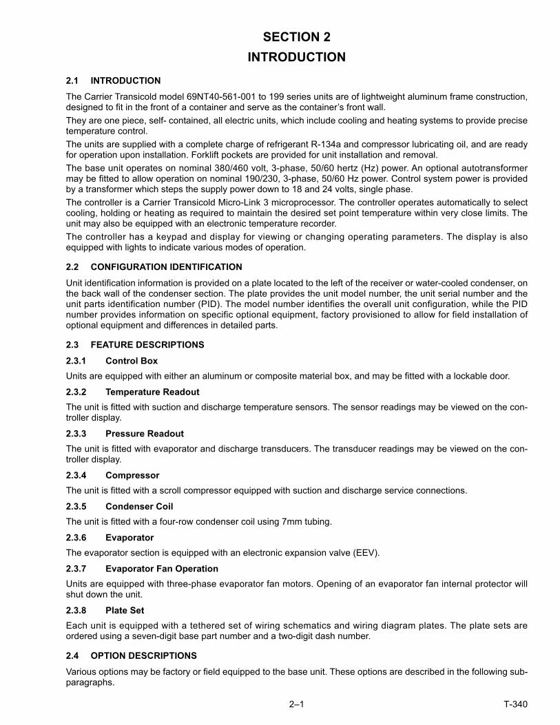
3.1.3 Evaporator Section
The evaporator section (Figure 3.2) contains the return temperature sensor, humidity sensor, electronic expansionvalve, dual speed evaporator fans (EM1 and EM2), evaporator coil and heaters, defrost temperature sensor, heattermination thermostat and evaporator temperature sensors (ETS1 and ETS2).
The evaporator fans circulate air through the container by pulling it in the top of the unit, directing it through theevaporator coil, where it is heated or cooled, and discharging it at the bottom.
If the unit is equipped with eAutoFresh, system components are mounted in addition to the standard refrigerationunit components. The stepper motor component is installed in the vent; the air filter, CO2 sensor, stepper motordrive and CO2 sensing lines are installed on the rib of the upper grill.
Most evaporator components are accessible by removing the upper rear panel (as shown in the illustration) or byremoving the evaporator fan access panels (see Figure 3.1, Items 1 and 19).
Figure 3.2 Evaporator Section
1. Evaporator Fan Motor #1 (EM1)2. Return Recorder Sensor/Temperature Sensor
(RRS/RTS)3. Humidity Sensor (HS)4. Evaporator Fan Motor #2 (EM2)5. Evaporator Coil6. Evaporator Coil Heaters (Underside of Coil)7. Heater Termination Thermostat (HTT)8. Defrost Temperature Sensor (DTS)9. Electronic Expansion Valve (EEV)10. Evaporator Temperature Sensors (Location) (ETS1
and ETS2)
11. Air Filter12. CO2 Sensor Sensing Line13. CO2 Sensor (COS)14. CO2 Sensor Outlet Line15. Stepper Motor Drive (SD)16. Stepper Motor (AF)17. Interrogator Connector (Rear) (ICR)18. USDA Probe Receptacle PR219. USDA Probe Receptacle PR120. USDA Probe Receptacle PR321. Cargo Probe Receptacle PR4
- - - - -
12
34
6
5
7
8
9
10
11
12
13
14
15
16
17
18
1920
21

3–3 T-340
3.1.4 Compressor Section
The compressor section (Figure 3.3) includes the compressor, digital unloader valve (DUV), high pressure switch,discharge pressure transducer (DPT), evaporator pressure transducer (EPT) and the suction pressure transducer(SPT).
The supply temperature sensor, supply recorder sensor, and ambient sensor are located to the left of the compressor.
Figure 3.3 Compressor Section
1. Compressor2. Compressor Discharge Temperature Sensor
(CPDS) (Location)3. Discharge Connection4. Suction Connection (Location)5. Compressor Terminal Box6. Oil Drain (Location)7. Economizer Connection8. Discharge Pressure Transducer (DPT)
9. Suction Pressure Transducer (SPT)10. Digital Unloader Valve (DUV)11. Evaporator Pressure Transducer (EPT)12. Discharge Service Valve13. High Pressure Switch (HPS)14. Warning Label15. Suction Service Valve16. Supply Temperature/Supply Recorder Sensor
Assembly (STS/SRS)- - - - -
12
4
5
6
7
8
9
10
11
12
13
14
15
16
3

T-340 3–4
3.1.5 Air-Cooled Condenser Section
The air-cooled condenser section (Figure 3.4) consists of the condenser fan, condenser coil, receiver, liquid lineservice valve, filter drier, fusible plug, economizer, economizer expansion valve, economizer solenoid valve (ESV),and sight glass/moisture indicator.
The condenser fan pulls air from around the coil and discharges it horizontally through the condenser fan grille.
Figure 3.4 Air-Cooled Condenser Section
1. Grille and Venturi Assembly2. Condenser Fan3. Key4. Condenser Fan Motor5. Condenser Coil6. Condenser Coil Cover7. Receiver8. Sight Glass
9. Filter Drier10. Economizer11. Economizer Solenoid Valve (ESV)12. Economizer Expansion Valve13. Warning Label (location)14. Service Access Valve15. Liquid Level/Moisture Indicator16. Fusible Plug
- - - - -
1
2 3 4
5
6
7
8 9 10
11
12
14
15
16
13

3–5 T-340
3.1.6 Water-Cooled Condenser Section
The water-cooled condenser section (Figure 3.5) consists of a water-cooled condenser, sight glass, rupture disc,filter drier, water couplings, water pressure switch, economizer, economizer expansion valve, economizer solenoidvalve (ESV), and moisture/liquid indicator.
The water-cooled condenser replaces the standard unit receiver.
Figure 3.5 Water-Cooled Condenser Section
1. Water-Cooled Condenser2. Rupture Disc3. Moisture/Liquid Indicator4. Filter Drier5. Economizer6. Economizer Solenoid Valve (ESV)
7. Economizer Expansion Valve8. Coupling (Water In)9. Liquid Line Service Valve/Connection10. Self Draining Coupling (Water Out)11. Water Pressure Switch (WP)12. Sight Glass
- - - - -
1
32 4 5
6
7
89101112

T-340 3–6
3.1.7 Control Box Section
The control box (Figure 3.6) includes: the manual operation switches, circuit breaker (CB-1), compressor, fan andheater contactors, control power transformer, fuses, key pad, display module, current sensor module, controllermodule and the communications interface module.
3.1.8 Communications Interface Module
The communications interface module is a slave module which allows communication between the refrigerationunit and a ship system master central monitoring station. The module will respond to communication and returninformation over the ships main power line. Refer to the master system technical manual for further information.
Figure 3.6 Control Box Section
1. Compressor Contactor - CH2. Compressor Phase A Contactor - PA3. Compressor Phase B Contactor - PB4. Heater Contactor - HR5. Display Module6. Communications Interface Module7. Controller/DataCORDER Module (Controller)8. Keypad9. Remote Monitoring Receptacle
10. Start-Stop Switch, ST11. Controller Battery Pack (Standard Location)12. Interrogator Connector (Box Location)13. Control Transformer14. High Speed Evaporator Fan Contactor - EF15. Low Speed Evaporator Fan Contactor - ES16. Condenser Fan Contactor - CF17. Circuit Breaker - 460V18. Current Sensor Module
- - - - -
1 2 3 4 5 6 7 8
9
10
1112131415161718

3–7 T-340
3.2 REFRIGERATION SYSTEM DATA
a. Compressor/Motor Assembly
Model Number ZMD26KVE-TFD-272
Weight (With Oil) 42.9 kg (95 lb)
Approved Oil Uniqema Emkarate RL-32-3MAF
Oil Charge 1774 ml (60 ounces)
b. Electronic Expansion Valve Superheat(Evaporator)
Verify at -18°C(0F) container boxtemperature
4.4 to 6.7°C (8 to 12°F)
c. Economizer Expansion Valve Superheat
Verify at -18°C(0F) container boxtemperature
4.4 to 11.1°C (8 to 20°F)
d. Heater Termination Thermostat
Opens 54° (+/- 3) C = 130° (+/- 5) F
Closes 38° (+/- 4) C = 100° (+/- 7) F
e. High Pressure Switch Cut-Out 25 (+/- 1.0) kg/cm2 = 350 (+/- 10) psig
Cut-In 18 (+/- 0.7) kg/cm2 = 250 (+/- 10) psig
WARNING!EXPLOSION HAZARD: Failure to follow this WARNING can result in death, serious personalinjury and / or property damage.Never use air or gas mixtures containing oxygen (O2) for leak testing or operating the product.Charge Only With R-134a: Refrigerant must conform to AHRI Standard 700 specification.
f. Refrigerant R-134a Conforming to AHRI standard 700 specifications.
CAUTION!Charge water-cooled condenser or receiver according to nameplate specifications to ensureoptimal unit performance.
g. Refrigerant ChargeWater-Cooled Condenser 5.44 kg (12 lbs)
Receiver 4.99 kg (11 lbs)
h. Fusible Plug Melting point 99°C = (210°F)
Torque 6.2 to 6.9 mkg (45 to 50 ft-lbs)
i. Rupture Disc Bursts at 35 +/- 5% kg/cm2 = (500 +/- 5% psig)
Torque 6.2 to 6.9 mkg (45 to 50 ft-lbs)
j. Unit Weight Refer to unit model number plate.
k. Water Pressure Switch Cut-In 0.5 +/- 0.2 kg/cm2 (7 +/- 3 psig)
Cut-Out 1.6 +/- 0.4 kg/cm2 (22 +/- 5 psig)

T-340 3–8
3.3 ELECTRICAL DATA
a. Circuit Breaker
CB-1 (25 amp) Trips at 29 amps
CB-2 (50 amp) Trips at 62.5 amps
CB-2 (70 amp) Trips at 87.5 amps
b. Compressor Motor Full Load Amps (FLA) 13 amps @ 460 VAC
c. Condenser Fan Motor
380 VAC, Three Phase, 50 Hz
460 VAC, Three Phase, 60 Hz
Full Load Amps 1.3 amps 1.6 amps
Horsepower 0.43 hp 0.75 hp
Rotations Per Minute 1425 rpm 1725 rpm
Voltage and Frequency 360 - 460 VAC +/- 2.5 Hz 400 - 500 VAC +/- 2.5 Hz
Bearing Lubrication Factory lubricated, additional grease not required.
Rotation Counter-clockwise when viewed from shaft end.
d. Evaporator Coil Heaters
Number of Heaters 6
Rating 750 watts +5/-10% each @ 230 VAC
Resistance (cold) 66.8 to 77.2 ohms @ 20°C (68°F)
Type Sheath
e. Evaporator Fan Motor(s)
380 VAC/3 PH/50 Hz 460 VAC/3 PH/60 Hz
Full Load AmpsHigh Speed
1.0 1.2
Full Load AmpsLow Speed
0.6 0.6
Nominal HorsepowerHigh Speed
0.49 0.84
Nominal HorsepowerLow Speed
0.06 0.11
Rotations Per MinuteHigh Speed
2850 rpm 3450 rpm
Rotations Per MinuteLow Speed
1425 rpm 1725 rpm
Voltage and Frequency 360 - 460 VAC +/- 1.25 Hz 400 - 500 VAC +/- 1.5 Hz
Bearing Lubrication Factory lubricated, additional grease not required
Rotation CW when viewed from shaft end
f. Fuses
Control Circuit 7.5 amps (F3A,F3B)
Controller/DataCORDER 5 amps (F1 & F2)
Emergency Bypass 10 amps (FEB)
g. Vent Positioning Sensor
Electrical Output 0.5 VDC to 4.5 VDC over 90 degree range
Supply Voltage 5 VDC +/- 10%
Supply Current 5 mA (typical)
h. Solenoid Valve Coils (ESV) 24 VDC
Nominal Resistance @77°F (25°C)
7.7 ohms +/- 5%
Maximum Current Draw 0.7 amps
i. DUV Coils 12 VDC
Nominal Resistance @77°F (20°C)
14.8 ohms +/- 5%
Maximum Current Draw 929 mA

3–9 T-340
3.4 SAFETY AND PROTECTIVE DEVICES
Unit components are protected from damage by safety and protective devices listed in Table 3–1. These devices moni-tor the unit operating conditions and open a set of electrical contacts when an unsafe condition occurs.
Open safety switch contacts on either or both of devices IP-CP or HPS will shut down the compressor.
Open safety switch contacts on device IP-CM will shut down the condenser fan motor.
The entire refrigeration unit will shut down if one of the following safety devices open: (a) circuit breaker(s); (b) fuse(F3A/F3B, 7.5A); or (c) evaporator fan motor internal protector(s) - (IP).
j. EEV Nominal Resis-tance
Coil Feed to Ground(Gray Wire)
47 ohms
Coil Feed to Coil Feed 95 ohms
k. Humidity Sensor
Orange wire Power
Red wire Output
Brown wire Ground
Input voltage 5 VDC
Output voltage 0 to 3.3 VDC
Output voltage readings verses relative humidity (RH) percentage:
30% 0.99 V
50% 1.65 V
70% 2.31 V
90% 2.97 V
Table 3–1 Safety and Protective Devices
UNSAFE CONDITION DEVICE DEVICE SETTING
Excessive current draw
Circuit Breaker (CB-1, 25 amp) - Man-ual Reset
Trips at 29 amps (460 VAC)
Circuit Breaker (CB-2, 50 amp) - Man-ual Reset
Trips at 62.5 amps (230 VAC)
Circuit Breaker (CB-2, 70 amp) - Man-ual Reset
Trips at 87.5 amps (230 VAC)
Excessive current draw in the control cir-cuit
Fuse (F3A & F3B) 7.5 amp rating
Excessive current draw by the control-ler
Fuse (F1 & F2) 5 amp rating
Excessive current draw by the Emer-gency Bypass module
Fuse (FEB) 10 amp rating
Excessive condenser fan motor wind-ing temperature
Internal Protector (IP-CM) - AutomaticReset
N/A
Excessive compressor motor winding temperature
Internal Protector (IP-CP) - AutomaticReset
N/A
Excessive evaporator fan motor(s) winding temperature
Internal Protector(s) (IP-EM) - Auto-matic Reset
N/A
Abnormal pressures/temperatures in the high refrigerant side
Fusible Plug - Used on the ReceiverRupture Disc - Used on the Water-Cooled Condenser
99°C = (210°F)35 kg/cm2 = (500 psig)
Abnormally high discharge pressure
High Pressure Switch (HPS) Opens at 25 kg/cm2
(350 psig)

T-340 3–10
3.5 REFRIGERATION CIRCUIT
3.5.1 Standard Operation
Starting at the compressor, (see Figure 3.7, upper schematic) the suction gas is compressed to a higher pressureand temperature.
The refrigerant gas flows through the discharge line and continues into the air-cooled condenser. When operatingwith the air-cooled condenser active, air flowing across the coil fins and tubes cools the gas to saturation tempera-ture. By removing latent heat, the gas condenses to a high pressure/high temperature liquid and flows to thereceiver, which stores the additional charge necessary for low temperature operation.
When operating with the water-cooled condenser active (see Figure 3.7, lower schematic), the refrigerant gaspasses through the air-cooled condenser and enters the water-cooled condenser shell. The water flowing insidethe tubing cools the gas to saturation temperature in the same manner as the air passing over the air-cooled con-denser. The refrigerant condenses on the outside of the tubes and exits as a high temperature liquid. The water-cooled condenser also acts as a receiver, storing refrigerant for low temperature operation.
The liquid refrigerant continues through the liquid line, the filter drier (which keeps refrigerant clean and dry) andthe economizer (not active during standard operation) to the electronic expansion valve (EEV).
As the liquid refrigerant passes through the variable orifice of the EEV, the pressure drops to suction pressure. Inthis process some of the liquid vaporizes to a gas (flash gas), removing heat from the remaining liquid. The liquidexits as a low pressure, low temperature, saturated mix. Heat is then absorbed from the return air by the balance ofthe liquid, causing it to vaporize in the evaporator coil. The vapor then flows through the suction tube back to thecompressor.
On systems fitted with a water pressure switch, the condenser fan will be off when there is sufficient pressure toopen the switch. If water pressure drops below the switch cut out setting, the condenser fan will automatically start.
During the standard mode of operation, the normally closed digital unloader valve (DUV) controls the system refrig-erant flow and capacity by loading and unloading the compressor in frequent discrete time intervals. If the systemcapacity has been decreased to the lowest allowable capacity with the DUV, the unit will enter a trim heat mode ofoperation, during which the controller will pulse the evaporator heaters in sequence with the compressor digital sig-nal in order to absorb the excess capacity.
3.5.2 Economized Operation
In the economized mode, (see Figure 3.8) the frozen and pull down capacity of the unit is increased by sub-coolingthe liquid refrigerant entering the electronic expansion valve. Overall efficiency is increased because the gas leavingthe economizer enters the compressor at a higher pressure, therefore requiring less energy to compress it to therequired condensing conditions.
Liquid refrigerant for use in the economizer circuit is taken from the main liquid line as it leaves the filter drier. Theflow is activated when the controller energizes the economizer solenoid valve (ESV).
The liquid refrigerant flows through the ESV to the expansion valve internal passages, absorbing heat from the liq-uid refrigerant flowing to the electronic expansion valve. The resultant “medium” temperature/pressure gas entersthe compressor at the economizer port fitting.
When the control air temperature falls to 2.0°C (3.6°F) above set point, the DUV unloads the compressor’s scrolland begins to reduce the capacity of the unit. Percentage of the unit capacity is accessed through code select 01(Cd01). For example, if Cd01 displays 70, it indicates that the compressor is operating unloaded with the DUVengaged 30% of the time.
3.5.3 Electronic Expansion Valve
The microprocessor controls the superheat leaving the evaporator via the electronic expansion valve (EEV), basedon inputs from the evaporator pressure transducer (EPT). The microprocessor transmits electronic pulses to theEEV stepper motor, which opens or closes the valve orifice to maintain the superheat set point.

3–11 T-340
Figure 3.7 Refrigeration Circuit Schematic - Standard Operation
STANDARD OPERATION WITH WATER-COOLED CONDENSER
CONDENSER
DISCHARGE LIQUID SUCTION
COMBOETS1 AND 2EVAPORATOR
DISCHARGE SERVICE VALVE
SUCTIONSERVICEVALVE
FILTERDRIER
LIQUID LINESERVICEVALVE
ECONOMIZERSOLENOIDVALVE
ECONOMIZERTXV
ELECTRONICEXPANSIONVALVE
DIGITALUNLOADERVALVE
ECONOMIZER
RECEIVER
COMPRESSOR
SIGHTGLASS
LIQUID LEVEL/MOISTUREINDICATOR
STANDARD OPERATION WITH RECEIVER
CONDENSER
ETS1 AND 2EVAPORATOR
DISCHARGE SERVICE VALVE
SUCTIONSERVICEVALVE
FILTERDRIER
LIQUID LINESERVICEVALVE
ECONOMIZERSOLENOIDVALVE
ECONOMIZERTXV
ELECTRONICEXPANSIONVALVE
DIGITALUNLOADERVALVE
ECONOMIZER
WATER COOLEDCONDENSER COMPRESSOR
SIGHTGLASS
MOISTUREINDICATOR
DISCHARGEPRESSURETRANSDUCER
DISCHARGEPRESSURETRANSDUCER
DISCHARGE TEMPERATURE SENSOR
DISCHARGE TEMPERATURE SENSOR
EVAPORATORPRESSURETRANSDUCER
SUCTIONPRESSURETRANSDUCER
ECON.TXV
SENSINGBULB
EVAPORATORPRESSURETRANSDUCER
SUCTIONPRESSURETRANSDUCER

T-340 3–12
Figure 3.8 Refrigeration Circuit Schematic - Economized Operation
LIQUID
LIQUID LINESERVICEVALVE
ECONOMIZERSOLENOIDVALVE
ECONOMIZERTXV
ELECTRONICEXPANSIONVALVE
ECONOMIZER
RECEIVERCOMPRESSOR
ECONOMIZER PRESSURE
ECON.TXV
SENSINGBULB

4–1 T-340
SECTION 4
MICROPROCESSOR
4.1 TEMPERATURE CONTROL MICROPROCESSOR SYSTEM
The temperature control Micro-Link 3 microprocessor system (see Figure 4.1) consists of a keypad, display mod-ule, the control module (controller) and interconnecting wiring. The controller houses the temperature control soft-ware and the DataCORDER software. The temperature control software functions to operate the unit componentsas required to provide the desired cargo temperature and humidity.
The DataCORDER software functions to record unit operating parameters and cargo temperature parameters forfuture retrieval. Coverage of the temperature control software begins with Section 4.2. Coverage of the Data-CORDER software is provided in Section 4.8.
The keypad and display module serve to provide user access and readouts for both of the controller functions, tem-perature control and DataCORDER. The functions are accessed by keypad selections and viewed on the displaymodule. The components are designed to permit ease of installation and removal.
Figure 4.1 Temperature Control System

T-340 4–2
4.1.1 Keypad
The keypad (Figure 4.2) is mounted on the right-hand side of the control box. The keypad consists of eleven pushbutton switches that act as the user’s interface with the controller. Descriptions of the switch functions are providedin Table 4–1.
Figure 4.2 Keypad Table 4–1 Keypad Function
4.1.2 Display Module
The display module (Figure 4.3) consists of two 5-digit displays and seven indicator lights. The indicator lights include:
1. COOL - White or Blue LED: Energized when the refrigerant compressor is energized.
2. HEAT - Orange LED: Energized to indicate heater operation in heat mode, defrost mode, or dehumidification.
3. DEFROST - Orange LED: Energized when the unit is in defrost mode.
4. IN RANGE - Green LED: Energized when the controlled temperature probe is within the specified toleranceof set point.
NOTEThe controlling probe in perishable range is the SUPPLY air probe and the controlling probe in frozenrange is the RETURN air probe.
CODESELECT
PRETRIP
ALARMLIST
MANUALDEFROST/INTERVAL
ENTER
BATTERYPOWER
ALTMODE
RETURNSUPPLY
CF
KEY FUNCTION
CODE SE-LECT
Accesses function codes.
PRE TRIP Displays Pre-trip selection menu.Discontinues Pre-trip in progress.
ALARM LIST Displays alarm list and clears thealarm queue.
MANUALDEFROST /INTERVAL
Displays selected defrost mode.Depress and hold the MANUAL DE-FROST / INTERVAL key for five (5) seconds to initiate defrost using the same logic as if the optional manual defrost switch was toggled on.
ENTER Confirms a selection or saves a selec-tion to the controller.
Arrow Up Change or scroll a selection up. Pre-trip advance or test interrupt.
Arrow Down Change or scroll selection downward. Pre-trip repeat backward.
RETURN /SUPPLY
Display non-controlling probe tem-perature (momentary display).
Celsius /Fahrenheit
Display alternate English/Metric scale (momentary display). When set to F, pressure is displayed in psig and vac-uum in “/hg.” “P” appears after the val-ue to indicate psig and “i” appears for inches of mercury. When set to C, pressure readings are in bars. “b” ap-pears after the value to indicate bars.
BATTERYPOWER
Initiate battery backup mode to allow set point & function code selection if AC power is not connected.
ALT MODE
This key is pressed to switch the func-tions from temperature software to the DataCORDER software. The re-maining keys function the same as described above except the readings or changes are made to the Data-CORDER programming.

4–3 T-340
5. SUPPLY - Yellow LED: Energized when the supply air probe is used for control. When this LED is illumi-nated, the temperature displayed in the AIR TEMPERATURE display is the reading at the supply air probe.This LED will flash if dehumidification or humidification is enabled.
6. RETURN - Yellow LED: Energized when the return air probe is used for control. When this LED is illumi-nated, the temperature displayed in the AIR TEMPERATURE display is the reading at the return air probe.
7. ALARM - Red LED: Energized when an active or an inactive shutdown alarm in the alarm queue.
Figure 4.3 Display Module
4.1.3 Controller
CAUTION!Do not remove wire harnesses from controller modules unless you are grounded to the unitframe with a static safe wrist strap.
CAUTION!Unplug all controller module wire harness connectors before performing arc welding on anypart of the container.
CAUTION!Do not attempt to use anML2i PC card in an ML3 equipped unit. The PC cards are physicallydifferent and will result in damage to the controller.
NOTEDo not attempt to service the controller modules. Breaking the seal will void the warranty.
The Micro-Link 3 controller is shown in Figure 4.4. It is fitted with test points, harness connectors and a softwarecard programming port.
4.2 CONTROLLER SOFTWARE
The controller software is a custom designed program that is subdivided into configuration software and opera-tional software. The controller software performs the following functions:
a. Control supply or return air temperature to required limits, provide modulated refrigeration operation, econo-mized operation, unloaded operation, electric heat control, and defrost. Defrost is performed to clear buildup offrost and ice to ensure proper air flow across the evaporator coil.
b. Provide default independent readouts of set point and supply or return air temperatures.
c. Provide ability to read and (if applicable) modify the configuration software variables, operating softwareFunction Codes and Alarm Code indications.
d. Provide a Pre-trip step-by-step checkout of refrigeration unit performance including: proper component opera-tion, electronic and refrigeration control operation, heater operation, probe calibration, pressure limiting and cur-rent limiting settings.
COOL HEAT DEFROST IN RANGE ALARM SUPPLY RETURN
SETPOINT/Code AIR TEMPERATURE/Data

T-340 4–4
e. Provide battery-powered ability to access or change selected codes and set point without AC power connected.
f. Provide the ability to reprogram the software through the use of a memory card.
4.2.1 Configuration Software (CnF Variables)
Configuration software is a variable listing of the components available for use by the operational software. Thissoftware is factory installed in accordance with the equipment fitted and options listed on the original purchaseorder. Changes to the configuration software are required only when a new controller has been installed or a phys-ical change has been made to the unit such as the addition or removal of an option. A configuration variable list isprovided in Table 4–4. Change to the factory-installed configuration software is achieved via a configuration card orby communications.
Figure 4.4 Control Module
1. Mounting Screw2. Micro-Link 3 Control/DataCORDER Module3. Connectors4. Test Points
5. Fuses6. Control Circuit Power Connection7. Software Programming Port8. Battery Pack (Standard Location)
- - - - -
4.2.2 Operational Software (Cd Function Codes)
The operational software is the actual operation programming of the controller which activates or deactivates com-ponents in accordance with current unit operating conditions and selected modes of operation.
The programming is divided into function codes. Some of the codes are read only, while the remaining codes maybe user configured. The value of the user configurable codes can be assigned in accordance with user desiredmode of operation. A list of the function codes is provided in Table 4–5.
To access the function codes:
a. Press CODE SELECT, then press an arrow key until the left window displays the desired function code.
b. The right window will display the selected function code value for five seconds before returning to normaldisplay mode.
c. If additional time is required, pressing the ENTER key will extend the display time to 30 seconds.
4.3 MODES OF OPERATION
General operation sequences for cooling, heating and defrost are provided in the following sub-paragraphs. Sche-matic representation of controller operation is provided in Figure 4.5 & Figure 4.8.
Operational software responds to various inputs. These inputs come from the temperature and pressure sensors,the temperature set point, the settings of the configuration variables and the function code assignments. The actiontaken by the operational software changes as the input values change. Overall interaction of the inputs is describedas a “mode” of operation. The modes of operation include perishable (chill) mode and frozen mode. Descriptions ofthe controller interaction and modes of operation are provided in the following sub-paragraphs.
MA CONTROLLER
Micro-Link3With
DataCORDERMB
MC F2 (5A
)
TP F1 (5A
)
F3A
(7.5
A)
F3B
(7.5
A)
KH
OC
1
KA
EN12830CARRIERS/N: 0491162T B C1 KE
REV 5147 YYWW:KD
1035KC
12-00579-0059980
KB
1 2 3 34 5 6 7 3 8 3

4–5 T-340
4.3.1 Start up - Compressor Phase Sequence
At start up, the controller logic checks for proper phase sequencing and compressor rotation. If incorrect sequenc-ing is causing the compressor and three-phase evaporator fan motors to rotate in the wrong direction, the controllerwill energize or de-energize relay TCP as required (see Figure 8.2). Relay TCP will switch its contacts, energizingor de-energizing relays PA and PB. Relay PA is wired to energize the circuits on L1, L2 and L3. Relay PB is wiredto energize the circuits on L3, L2, and L1, thus providing reverse rotation.
4.3.2 Start up - Compressor Bump Start
At start up, the controller logic will initiate a compressor bump start procedure to clear liquid refrigerant from thecompressor. If suction and discharge pressures have equalized, the compressor will perform three compressorbump starts. A compressor bump start may also occur after a defrost cycle has been completed.
During Bump Start, the EEV will close. Relays TS, TQ, TN, TE, and TV will be de-energized (opened). The result of thisaction will close the ESV and shut all fans off. The compressor will start for 1 second, then pause for five seconds. Thissequence will be repeated two more times. After the final bump start the unit will pre-position the EEV to the correctstarting position, pause and start up.
4.3.3 Perishable Mode Temperature Control
In Perishable Mode, the controller maintains the supply air temperature at set point, the SUPPLY indicator light isilluminated and the default reading on the display window is the supply temperature sensor reading.
When the supply air temperature enters the in-range temperature tolerance (Cd30), the green IN-RANGE light willenergize.
When CnF26 (Heat Lockout Temperature) is set to -10°C, perishable mode is active with set points above -10°C(+14°F). When CnF26 is set to -5°C, perishable mode is active with set points above -5°C (+23°F).
4.3.4 Perishable Pulldown
When the system is in Perishable Pulldown Mode, the highest priority is given to bringing the container down to setpoint. When cooling from a temperature that is more than 2.5°C (4.5°F) above set point, the system will be in perish-able pulldown mode in economized operation.
However, pressure and current limit functions may restrict the valve if either exceeds the preset value.
4.3.5 Perishable Steady State
Perishable Steady State is used to maintain the control temperature near a setpoint that is above the heat lockouttemperature.
Once set point is reached, the unit will transition to perishable steady state mode. This results in unloaded opera-tion by cycling the DUV to limit capacity and maintain steady temperature control.
The unit is capable of maintaining supply air temperature to within +/-0.2°C (+/-0.36°F) of set point. Supply air tem-perature is controlled by positioning of the electronic expansion valve (EEV), cycling of the digital unloader valve(DUV), cycling of the compressor, and cycling of the heaters.
4.3.6 Perishable Idle, Air Circulation
Perishable Idle Mode is used when it is unnecessary to run the compressor to maintain control temperature. If thecontroller has determined that cooling is not required or the controller logic determines suction pressure is at thelow pressure limit, the unit will transition to Perishable Idle Mode. During Perishable Idle Mode, the compressor isturned off, but the evaporator fans continue to run to circulate air throughout the container. If temperature rises+0.2°C above set point, the unit will transition back to perishable steady state.
4.3.7 Perishable Heating
When it is necessary to raise the control temperature, the system will enter Perishable Heating Mode. If the tem-perature drops to 0.5°C (0.9°F) below set point, the unit will transition to Perishable Heating Mode, and the heaterswill be energized. The unit will transition back to Perishable Idle Mode when the temperature rises to 0.2°C (0.4°F)below the set point, and the heaters will de-energize.

T-340 4–6
Figure 4.5 Controller Operation - Perishable Mode
4.3.8 Perishable Dehumidification
Dehumidification is provided to reduce the humidity levels inside the container. Dehumidification is activated when ahumidity value is set at Cd33. The yellow SUPPLY LED will flash ON and OFF every second to indicate that dehumidifi-cation is active. Once dehumidification is active and the following conditions are satisfied, the controller will activate theheat relay to begin dehumidification.
1. The humidity sensor reading is above the humidity set point (Cd33).
2. The unit is in perishable steady state and supply air temperature is less than 0.25°C (0.45°F) above set point.
3. The heater debounce timer (three minutes) has timed out.
4. Heater termination thermostat (HTT) is closed.
If the above conditions are true for at least one hour the evaporator fans will switch from high speed to low speed.Evaporator fan speed will then switch every hour, as long as the 4 conditions are met (see Bulb Mode, Section 4.3.9for different evaporator fan speed options).
If any condition except item (1) becomes false OR if the relative humidity sensed is 2% below the dehumidificationset point, the high speed evaporator fans will be energized.
During dehumidification power is applied to the defrost heaters. This added heat load causes the controller to openthe EEV to match the increased heat load while still holding the supply air temperature very close to the set point.
Opening the EEV reduces the temperature of the evaporator coil surface, which increases the rate at which wateris condensed and removes water from the passing air. Removing water from the air reduces the relative humidity.When the relative humidity sensed is 2% below set point, the controller de-energizes the heat relay. The controllerwill continue to cycle heating to maintain relative humidity below the selected set point. If dehumidification is termi-nated by a condition other than the humidity sensor, e.g., an out-of-range or compressor shutdown condition, theheat relay is de-energized immediately.
Controller Set Point ABOVE −10°C (+14 °F),or−5°C (+23 °F) optionally
−.20 °C
−.50 °C
+.20 °C
−.20 °CAir Circulation
Heating
Cooling,Unloaded
Controller Set Point ABOVE −10°C (+14 °F),or−5°C (+23 °F) optionally
−.20 °C
−.50 °C
−.20 °CAir Circulation
Heating
Cooling,Economized
Pull Down
+2.5 °C(+4.5 °F)
Cooling, Unloaded
Falling Temperature
Rising Temperature
Perishable Mode(Only Applicable to Perishable Mode)
SetPoint

4–7 T-340
Two timers are activated during dehumidification to prevent rapid cycling and consequent contactor wear:
1. Heater debounce timer (three minutes) - The heater debounce timer is started whenever the heater contac-tor status is changed. The heat contactor remains energized (or de-energized) for at least three minuteseven if the set point criteria are satisfied.
2. Out-of-range timer (five minutes) - The out-of-range timer is started to maintain heater operation during atemporary out-of-range condition. If supply air temperature remains outside of the user selected in-rangesetting for more than five minutes, the heaters will be de-energized to allow the system to recover. The out-of-range timer starts as soon as temperature exceeds in-range tolerance value set by Cd30.
4.3.9 Perishable Dehumidification - Bulb Mode
Bulb mode is an extension of dehumidification which allows changes to the evaporator fan speed and/or defrosttermination set points.
Bulb mode is active when Cd35 is set to “Bulb.” Once bulb mode is activated, the user may then change dehumid-ification evaporator fan operation from the default (speed alternates from low to high each hour) to constant low orconstant high speed. This is done by toggling Cd36 from its default of “alt” to “Lo” or “Hi” as desired. If low speedevaporator fan operation is selected, this gives the user the additional capability of selecting dehumidification setpoints from 60 to 95% (instead of the normal 65 to 95%).
In addition, if bulb mode is active, Cd37 may be set to override the previous defrost termination thermostat (DTT)settings. The temperature at which the DTT will be considered “open” may be changed [in 0.1°C(0.2°F) incre-ments] to any value between 25.6°C (78°F) and 4°C (39.2°F). The temperature at which the DTT is consideredclosed for interval timer start or demand defrost is 10°C (50°F) for “open” values from 25.6°C (78°F)down to a10°C(50°F) setting. For “open” values lower than 10°C, the “closed” values will decrease to the same value as the“open” setting. Bulb mode is terminated when:
1. Bulb mode code Cd35 is set to “Nor.”
2. Dehumidification code Cd33 is set to “Off.”
3. The user changes the set point to one that is in the frozen range.
When bulb mode is disabled by any of the above conditions, evaporator fan operation for dehumidification revertsto “alt” and the DTS termination setting resets to the value determined by CnF41.
4.3.10 Perishable Economy
Economy fan mode is an extension of the Perishable Mode, and is provided for power saving purposes. Economyfan mode is activated when Cd34 (also used for Frozen Economy Mode) is set to “ON.” Economy fan mode is usedin the transportation of temperature-tolerant cargo or non-respiration items which do not require high airflow forremoving respiration heat.
There is no active display that indicates that economy fan mode has been initiated. To check for economy fanmode, perform a manual display of Cd34.
In order to initiate economy fan mode, a perishable set point must be selected prior to activation. When economyfan mode is active, the evaporator fans will be controlled as follows:
At the start of each cooling or heating cycle, the evaporator fans will run in high speed for three minutes.They will then be switched to low speed any time the supply air temperature is within +/- 0.2°C (0.36°F) ofthe set point and the return air temperature is less than or equal to the supply air temperature +3°C (5.4°F).The fans will continue to run in low speed for one hour. At the end of the hour, the evaporator fans willswitch back to high speed and the cycle will be repeated. If bulb mode is active, economy fan mode will beoverridden.
4.3.11 Perishable Mode Cooling - Sequence of Operation
NOTEIn Standard Perishable Mode, the evaporator motors run in high speed. In Economy Fan Mode, thefan speed is varied.
a. When supply air temperature is above set point and decreasing, the unit will cool with the condenser fanmotor (CF), compressor motor (CH), and evaporator fan motors (EF) energized, and the white COOL lightilluminated. (See Figure 4.6). Also, if current or pressure limiting is not active, the controller will close con-tacts TS to open the economizer solenoid valve (ESV) and place the unit in economized operation.

T-340 4–8
Figure 4.6 Perishable Mode Cooling
b. When supply air temperature decreases to a predetermined tolerance above set point (Cd30), the green INRANGE light is illuminated.
c. As air temperature continues to fall, unloaded cooling starts (DUV pulses opens) as the supply air tempera-ture approaches set point. (See Figure 4.5).
d. When unloaded cooling starts, EEV control will transition from a full cool superheat set point to a lower mod-ulated cool superheat set point. Once unloading starts, the EEV controls evaporator superheat based on thesystem duty cycle where instantaneous superheat will vary.
e. When the supply air temperature has fallen to within 1.9°C (3.4°F) of set point temperature and the averagecapacity of the system has fallen below 70%, the unit will open contacts TS to close the ESV and take theunit out of economized operation.
f. The controller continuously monitors supply air temperature. Once the supply air temperature falls below setpoint, the controller periodically records supply air temperature, set point and time. A calculation is then per-formed to determine temperature drift from set point over time. If the calculation determines that cooling is nolonger required, contacts TC and TN are opened to de-energize the compressor motor and the condenser fanmotor. In addition the controller will close the EEV.
g. The evaporator fan motors continue to run to circulate air throughout the container. The green IN RANGElight remains illuminated as long as the supply air temperature is within tolerance of the set point.
h. If the supply air temperature increases to 1.0°C (1.8°F) above set point and three minutes have elapsed,contacts TC and TN close to restart the compressor and condenser fan motors in standard mode (non-economized) operation. The white COOL light is also illuminated.
i. If the average system capacity has risen to 100% during unloaded cooling and three minutes off time haselapsed, relay TS will energize to open the ESV, placing the unit in economized mode.
j. If the supply air increases more than 2.5°C (4.5°F) above set point temperature, the microprocessor will transi-tion the evaporator superheat control from modulation back to full cool control.
4.3.12 Perishable Mode Heating - Sequence of Operation
a. If the supply air temperature decreases 0.5°C (0.9°F) below set point, the system enters the heating mode.(See Figure 4.5). The controller closes contacts TH (see Figure 4.7) to allow power flow through the heattermination thermostat (HTT) to energize the heaters (HR). The orange HEAT light is also illuminated. Theevaporator fans continue to run to circulate air throughout the container.
b. When the supply air temperature rises to 0.2°C (0.4°F) below set point, contact TH opens to de-energize theheaters. The orange HEAT light is also de-energized. The evaporator fans continue to run to circulate airthroughout the container.
c. The safety heater termination thermostat (HTT) is attached to an evaporator coil circuit and will open theheating circuit if overheating occurs.
24 VOLT POWER
ENERGIZEDDE-ENERGIZED
TN
STF
HPS CH
IP-CM
TC
CF
TEIP-EM1 EFIP-EM2
HTT TH HR
ESVTS
TV EF ES
4–9 T-340
Figure 4.7 Perishable Mode Heating
NOTEThe EEV and DUV are independently operated by the microprocessor. For full diagrams and legend,see Section 8.
4.3.13 Perishable Mode - Trim Heat
If the system capacity has been decreased to the lowest allowable capacity and conditions exist that warrant max-imum temperature stability the controller will pulse the HR relay to energize the evaporator heaters in sequencewith the compressor digital signal.
4.3.14 Frozen Mode - Temperature Control
In Frozen Mode, the controller maintains the return air temperature at set point, the yellow RETURN indicator light isilluminated, and the default reading on the display window is the return temperature sensor (RTS) reading.
When the return air temperature enters the in-range temperature tolerance (Cd30), the green IN-RANGE light willenergize.
When CnF26 (Heat Lockout Temperature) is set to -10°C, frozen mode is active with set points below -10°C(+14°F). When CnF26 is set to -5°C, frozen mode is active with set points below -5°C (+23°F).
When the system is in Frozen Mode, the highest priority is given to bringing the container down to set point, thesystem will remain in economized operation.
4.3.15 Frozen Steady State
Frozen cargos are not sensitive to minor temperature changes, and the frozen temperature control system takesadvantage of this to greatly improve the energy efficiency of the unit. Frozen range temperature control is accom-plished by cycling the compressor on and off as the load demand requires.
Once the frozen set point is reached, the unit will transition to frozen steady state (economized operation).
4.3.16 Frozen Idle Mode
When temperature drops to set point minus 0.2°C (0.4°F) and the compressor has run for at least five minutes, theunit will transition to the frozen idle mode. The compressor is turned off and the evaporator fans continue to run tocirculate air throughout the container. If temperature rises above set point +0.2°C (0.4°F), the unit will transition backto the frozen steady state mode.
24 VOLT POWER
ENERGIZEDDE-ENERGIZED
TN
STF
HPS CH
IP-CM
TC
CF
TEIP-EM1 EFIP-EM2
HTT TH HR
ESVTS
TV EF ES

T-340 4–10
Figure 4.8 Controller Operation - Frozen Mode
4.3.17 Frozen “Heat” Mode
If the temperature drops 10°C (18°F) below set point, the unit will transition to the frozen “heating” mode. The evap-orator fans are brought to high speed, and the heat from the fans is circulated through the container. The unit willtransition back to frozen steady state when the temperature rises back to the transition point.
4.3.18 Frozen Economy Mode
In order to activate Frozen Economy Mode, a frozen set point temperature must be selected, and Cd34 (EconomyMode) set to “ON.” When economy mode is active, the system will perform normal frozen mode operations exceptthat the entire refrigeration system, excluding the controller, will be turned off when the control temperature is lessthan or equal to the set point -2°C (4°F). After an off-cycle period of 60 minutes, the unit will turn on high speedevaporator fans for three minutes, and then check the control temperature. If the control temperature is greaterthan or equal to the frozen set point +0.2°C (0.4°F), the unit will restart the refrigeration system and continue tocool until the off-cycle temperature criteria are met. If the control temperature is less than the frozen set point+0.2°C (0.4°F) the unit will turn off the evaporator fans and restart another 60 minute off-cycle.
4.3.19 Frozen Mode Cooling - Sequence of Operation
a. When the return air temperature is above set point and decreasing, the unit will transition to economizedcooling with the condenser fan motor (CF), compressor motor (CH), economizer solenoid valve (ESV), lowspeed evaporator fan motors (ES) energized and the white COOL light illuminated. (See Figure 4.9).
Controller Set Point at or BELOW −10°C (+14 °F),or −5°C (+23 °F) optionally
−.20 °C
+.20 °C
Air Circulation
Cooling,Economized
Set Point
+2.5 °C(+4.5 °F)
Frozen Mode
FallingTemperature
RisingTemperature

4–11 T-340
b. When the return air temperature decreases to a predetermined tolerance above set point, the green IN-RANGE light is illuminated.
c. When the return air temperature decreases to 0.2°C (0.4°F) below set point, contacts TC, TS and TN areopened to de-energize the compressor, economizer solenoid valve and condenser fan motor. The whiteCOOL light is also de-energized. The EEV will close.
d. The evaporator fan motors continue to run in low speed to circulate air throughout the container. The greenIN-RANGE light remains illuminated as long as the return air is within tolerance of set point.
e. If return air temperature drops to 10°C (18°F) or more below set point, the evaporator fans increase to highspeed.
f. When the return air temperature increases to 0.2°C (0.4°F) above set point and three minutes haveelapsed, the EEV opens and contacts TC, TS and TN close to restart the compressor, open the ESV andrestart the condenser fan motor. The white COOL is illuminated.
Figure 4.9 Frozen Mode
NOTEThe EEV and DUV are independently operated by the microprocessor. Complete schematics and leg-ends are located in Section 8.
4.3.20 Defrost
Defrost is initiated to remove ice buildup from the evaporator coil which can obstruct air flow and reduce the coolingcapacity of the unit. The defrost cycle may consist of up to three distinct operations. The first is de-icing of the coil, thesecond is defrost due to a probe check cycle, and the third is a snap freeze.
Defrosting the coil consists of removing power to the cooling components (compressor, evaporator fans, and con-denser fan), closing the EEV, and turning on the heaters, which are located below the evaporator coil. During nor-mal operation, de- icing will continue until temperatures indicate that the ice on the coil has been removed, properair flow has been restored, and the unit is ready to control temperature efficiently.
After de-icing, and depending on unit configuration, a Defrost/Probe Check and/or Snap Freeze may occur:
During Defrost / Probe Check, the evaporator fans are allowed to run for a period of time after de-icing inorder to validate the accuracy of the temperature sensors, and confirm that defrost was executed properly.Refer to Section 5.10, Probe Diagnostics for additional information.
Defrost / Snap Freeze allows the system to cool for a period of time after de-icing, with the evaporator fansturned off. This allows for the removal of latent de-icing heat from the evaporator coils, and freezes anyremaining moisture that might otherwise be blown into the container.
24 VOLT POWER
ENERGIZEDDE-ENERGIZED
TN
STF
HPS CH
IP-CM
TC
CF
TEIP-EM1 EFIP-EM2
HTT TH HR
ESVTS
TV EF ES

T-340 4–12
4.3.21 Automatic Defrost
In perishable mode, perishable-pull down mode, or frozen mode, automatic defrost starts with an initial defrost setto three hours and then adjusts the interval to the next defrost based on the accumulation of ice on the evaporatorcoil. In this way, defrosts are scheduled to occur only when necessary.
In frozen mode, once the frozen set point has been reached, automatic defrost will set the time interval to 12 hoursfor the first two defrosts, and then adjust to 24 hours thereafter.
All defrost interval times reflect the number of compressor run time hours since the last defrost cycle. The minimumdefrost interval in the automatic setting is three hours while the maximum is 24, refer to Section 4.3.22, DefrostIntervals for more information.
In frozen mode the amount of actual time necessary to accumulate defrost interval time will exceed the defrostinterval time by a factor of two to three depending on the compressor duty-cycle. Defrost interval time is only accu-mulated when the compressor is running, and the Defrost Termination Sensor (DTS) reads less than 10°C (50°F),at which point the Defrost Termination Thermostat (DTT) is considered closed.
If defrost does not terminate correctly and temperature reaches the set point of the Heat Termination Thermostat (HTT),the HTT will open to de-energize the heaters (AL59 & AL60). If the HTT does not open and termination does not occurwithin two hours, the controller will terminate defrost. AL60 will be activated to inform of a possible DTS failure.
4.3.22 Defrost Initiation
Initiation of defrost is dependent on the state of the Defrost Temperature Thermostat (DTT). The functionality of theDTT is controlled by the system software, based on the temperature reading of the Defrost Termination Sensor(DTS). In the case of a failed DTS, the RTS may be used to determine the state of the DTT.
Defrost cannot be initiated when the DTT is considered OPEN, because an open DTT indicates that the tempera-ture is too high for ice to build up. Defrost can only occur when the temperature sensed by the DTS is low
enough to CLOSE the DTT.
If the DTT is closed, the unit is in Perishable or Frozen Mode, and the Controlled Atmosphere Vent is closed (ifapplicable), then defrost can be initiated when any one of the following additional conditions become true:
1. Manual defrost is initiated by the operator. The Manual Defrost Switch (MDS), located on the front of theunit, is a momentary toggle switch that must be held closed until defrost is initiated. The MDS is ignoredduring Pretrip, and the DTT must be considered CLOSED for MDS activation to work.
Manual defrost can also be initiated by pressing the MANUAL DEFROST/INTERVAL key for greater than 5seconds, or pressing the PRE TRIP key and the ALT MODE key for greater than 5 seconds. If the two keymethod is used the display may show “P” or “Dc” while waiting for defrost to initiate.
2. The Defrost Interval Timer reaches or exceeds the Defrost Interval.
3. During Pretrip, defrost may occur during tests P-8, and P-10. Defrost is forced during Pretrip test P-9.
4. Temperature Probe Diagnostics logic determines that a Probe Check is necessary based on temperaturevalues currently reported by the supply and return probes.
5. An Initiate Defrost command is sent via communications.
6. The microprocessor can determine if defrost is required by calculating the difference between return air tem-perature and supply air temperature (Delta T). If the temperature difference between return air and supplyair is too great, it indicates reduced airflow over the evaporator coil, and a defrost cycle may be required:
a. In Perishable Pull Down - Defrost will be initiated if Delta T increases to greater than 12°C, DTT isclosed, and 90 minutes of compressor run time have been recorded.
b. In Frozen Mode - Defrost will be initiated if Delta T increases to greater than 16°C, DTT is closed, and 90minutes of compressor run time have been recorded.
c. In Perishable Steady State - A baseline Delta T is used to determine when defrost should be activated.The baseline is recorded after completion of an initial defrost cycle. In order to record a baseline Delta T,the unit must be cooling, and the evaporator fans and heaters must remain in a stable state for a periodof five minutes. Defrost will then be initiated if Delta T increases to greater than 4°C above the baseline,the DTT is closed, and 90 minutes of compressor run time have been recorded.
NOTEDuring defrost, the Defrost Relay is energized, the orange DEFROST light is illuminated, and theorange HEAT light is illuminated.
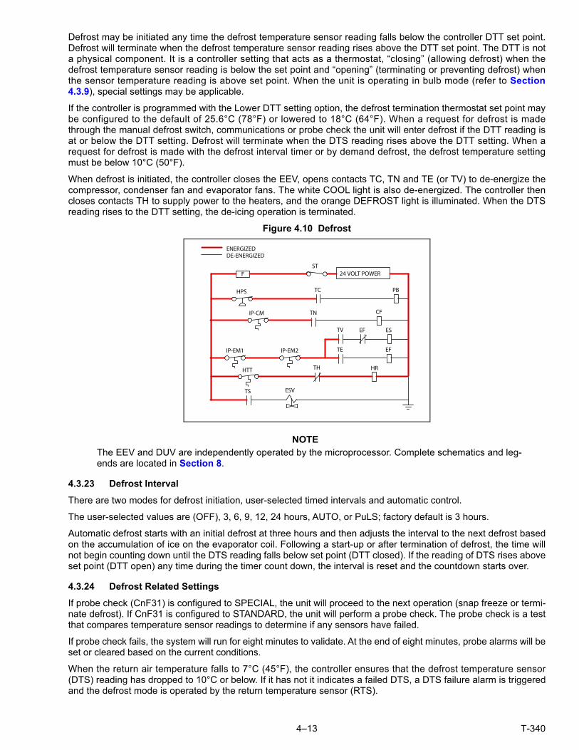
4–13 T-340
Defrost may be initiated any time the defrost temperature sensor reading falls below the controller DTT set point.Defrost will terminate when the defrost temperature sensor reading rises above the DTT set point. The DTT is nota physical component. It is a controller setting that acts as a thermostat, “closing” (allowing defrost) when thedefrost temperature sensor reading is below the set point and “opening” (terminating or preventing defrost) whenthe sensor temperature reading is above set point. When the unit is operating in bulb mode (refer to Section4.3.9), special settings may be applicable.
If the controller is programmed with the Lower DTT setting option, the defrost termination thermostat set point maybe configured to the default of 25.6°C (78°F) or lowered to 18°C (64°F). When a request for defrost is madethrough the manual defrost switch, communications or probe check the unit will enter defrost if the DTT reading isat or below the DTT setting. Defrost will terminate when the DTS reading rises above the DTT setting. When arequest for defrost is made with the defrost interval timer or by demand defrost, the defrost temperature settingmust be below 10°C (50°F).
When defrost is initiated, the controller closes the EEV, opens contacts TC, TN and TE (or TV) to de-energize thecompressor, condenser fan and evaporator fans. The white COOL light is also de-energized. The controller thencloses contacts TH to supply power to the heaters, and the orange DEFROST light is illuminated. When the DTSreading rises to the DTT setting, the de-icing operation is terminated.
Figure 4.10 Defrost
NOTEThe EEV and DUV are independently operated by the microprocessor. Complete schematics and leg-ends are located in Section 8.
4.3.23 Defrost Interval
There are two modes for defrost initiation, user-selected timed intervals and automatic control.
The user-selected values are (OFF), 3, 6, 9, 12, 24 hours, AUTO, or PuLS; factory default is 3 hours.
Automatic defrost starts with an initial defrost at three hours and then adjusts the interval to the next defrost basedon the accumulation of ice on the evaporator coil. Following a start-up or after termination of defrost, the time willnot begin counting down until the DTS reading falls below set point (DTT closed). If the reading of DTS rises aboveset point (DTT open) any time during the timer count down, the interval is reset and the countdown starts over.
4.3.24 Defrost Related Settings
If probe check (CnF31) is configured to SPECIAL, the unit will proceed to the next operation (snap freeze or termi-nate defrost). If CnF31 is configured to STANDARD, the unit will perform a probe check. The probe check is a testthat compares temperature sensor readings to determine if any sensors have failed.
If probe check fails, the system will run for eight minutes to validate. At the end of eight minutes, probe alarms will beset or cleared based on the current conditions.
When the return air temperature falls to 7°C (45°F), the controller ensures that the defrost temperature sensor(DTS) reading has dropped to 10°C or below. If it has not it indicates a failed DTS, a DTS failure alarm is triggeredand the defrost mode is operated by the return temperature sensor (RTS).
24 VOLT POWER
ENERGIZEDDE-ENERGIZED
TN
STF
HPS PB
IP-CM
TC
CF
TEIP-EM1 EFIP-EM2
HTT TH HR
ESVTS
TV EF ES
T-340 4–14
If controller function code CnF33 is configured to snap freeze, the controller will sequence to this operation. Thesnap freeze consists of running the compressor without the evaporator fans in operation for a period of 4 minutesat 100% capacity. When the snap freeze is completed, defrost is terminated.
If CnF23 is configured to “SAv” (save), then the value of the defrost interval timer will be saved at power down andrestored at power up. This option prevents short power interruptions from resetting an almost expired defrost interval,and possibly delaying a needed defrost cycle.
CnF11 determines whether the operator will be allowed to chose “OFF” as a defrost interval option.
CnF64 determines whether the operator will be allowed to choose “PuLS” as a defrost interval option. For unitsoperating with “PuLS” selected, defrost interval is determined by the unit temperature setpoint and the EvaporatorFan Pulsing Temperature Setting (Cd60). When the unit temperature setpoint is equal to or less than the Evapora-tor Fan Pulsing Temperature Setting, the defrost interval is set to 6 hours. Otherwise, the defrost interval is deter-mined using the Automatic Defrost Interval Determination logic. In either case, “PuLS” remains displayed in thisfunction select code.
After a new Defrost Interval is selected, the previously selected Interval is used until the next defrost termination,the next time the DTT contacts are OPEN, or the next time power to the control is interrupted. If the previous valueor the new value is “OFF”, the newly selected value will be used immediately.
If any Auto Pretrip sequence is initiated, Cd27 will be set to ‘AUTO’ unless CnF49 (OEM Reset) is set to “Custom”AND CnF64 (Evaporator Fan Pulsing Logic) configuration variable is set to IN, in which case Cd27 will be set to“PuLS”.
4.4 PROTECTION MODES OF OPERATION
4.4.1 Evaporator Fan Operation
Opening of an evaporator fan internal protector will shut down the unit.
4.4.2 Failure Action
Function code Cd29 may be operator set to select the action the controller will take upon a system failure. The fac-tory default is full system shutdown. Refer to Table 4–5.
4.4.3 Generator Protection
Function codes Cd31(Stagger Start, Offset Time) and Cd32 (Current Limit) may be operator set to control the startup sequence of multiple units and operating current draw. The factory default allows on demand starting (no delay)of units and normal current draw. Refer to Table 4–5.
4.4.4 Compressor High Temperature, Low Pressure Protection
The controller continuously monitors compressor discharge pressure and temperature, and suction pressure. Ifdischarge pressure or temperature rises above the allowed limit or suction pressure falls below the allowed limit,the compressor will be cycled off and on every 3 minutes. Condenser and evaporator fans will continue to operateduring the compressor off cycle.
If high compressor dome temperature occurs, as measured by the CPDS, the controller will allow additional refrig-erant to be released into the system in order to provide cooling to the evaporator coil and compressor dome. Thecontroller is alerted to high compressor dome temperatures via the CPDS when ambient temperature is greaterthan 43.3°C, return air temperature is less than -17.5°C and the compressor discharge temperature is greater than117.7°C.
Dome temperature control logic will disengage when return air temperature and ambient temperature return toallowed limits or when the compressor turns off.
If the suction pressure low limit is triggered, the DUV will energize to raise the suction pressure.
4.4.5 Perishable Mode - System Pressure Regulation
In perishable mode, system pressures may need to be regulated at ambient temperatures of 20°C (68°F) andbelow. Once below this ambient temperature, the condenser fan may cycle on and off based on limits imposed fordischarge pressure. For extremely cold ambient temperatures, -18°C (0°F), heater cycling may occur within normalsystem operation based on discharge pressure limits.

4–15 T-340
4.4.6 Condenser Fan Override
When CnF17 (Discharge Temperature Sensor) is set to “In” and CnF48 (Condenser Fan Switch Override) is set to“On”, the condenser fan switch override logic is activated. If condenser cooling water pressure is sufficient to openthe water pressure switch (de-energizing the condenser fan) when water flow or pressure conditions are not main-taining discharge temperature, the logic will energize the condenser fan as follows:
1. If the DUV is less than 80% open when the controller calls for it to be100% open, the condenser fan is ener-gized. When the DUV is 100% open, the fan will de-energize.
2. If DPT reading is invalid or out of range (AL65), the condenser fan is energized and will remain energizeduntil system power is cycled.
3. If the system is running on condenser fan override and the high pressure switch opens, the condenser fan isenergized and will remain energized until the system power is cycled.
4.5 QUEST - CCPC
Compressor-Cycle Perishable Cooling (CCPC) is a method of temperature control used during steady-state perish-able cooling that cycles the compressor on and off according to return air temperature.
To be eligible for steady-state control the unit must first complete a setpoint pulldown phase and a CCPC pulldownphase:
• During setpoint pulldown supply air temperature is controlled according to the unit’s nominal supply air setpoint.
• During CCPC pulldown the supply air temperature is lowered somewhat relative to the nominal setpoint.Evaporator fans are forced to operate at high speed.
Steady-state CCPC control maintains the same lowered supply air temperature that was used during CCPC pull-down. The compressor cycles on and off according to return air high and low limits. Depending on the fan mode ofoperation selected, the evaporator fans may be programmed to run at low speed some or all of the time accordingto the control logic.
4.6 CONTROLLER ALARMS
Alarm display is an independent controller software function. If an operating parameter is outside of expectedrange or a component does not return the correct signals back to the controller, an alarm is generated. A listing ofthe alarms is provided in Table 4–6.
The alarm philosophy balances the protection of the refrigeration unit and that of the refrigerated cargo. The actiontaken when an error is detected always considers the survival of the cargo. Rechecks are made to confirm that anerror actually exists.
Some alarms requiring compressor shutdown have time delays before and after to try to keep the compressor on line.An example is alarm code “LO,” (low main voltage), when a voltage drop of over 25% occurs, an indication is given onthe display, but the unit will continue to run.
When an Alarm Occurs:
a. The red alarm light will illuminate for alarm code numbers 15, 17, 20, 21, 22, 23, 24, 25, 26, and 27.
b. If a detectable problem exists, its alarm code will be alternately displayed with the set point on the left display.
c. The user should scroll through the alarm list to determine what alarms exist or have existed. Alarms must bediagnosed and corrected before the Alarm List can be cleared.
To Display Alarm Codes:
a. While in the Default Display mode, press the ALARM LIST key. This accesses the Alarm List Display Mode,which displays any alarms archived in the alarm queue.
b. The alarm queue stores up to 16 alarms in the sequence in which they occurred. The user may scrollthrough the list by depressing an ARROW key.
c. The left display will show “AL##,” where ## is the alarm number sequentially in the queue.
d. The right display will show the actual alarm code. “AA##” will display for an active alarm, where “##” is thealarm code. Or “IA##” will display for an inactive alarm, see Table 4–6.
e. “END” is displayed to indicate the end of the alarm list if any alarms are active.
T-340 4–16
f. “CLEAr” is displayed if all alarms are inactive. The alarm queue may then be cleared by pressing ENTER.The alarm list will clear and “-----” will be displayed.
NOTEAL26 is active when none of the sensors are responding. Check the connector at the back of the con-troller; if it is loose or unplugged, reconnect it, then run a Pre-trip test (P5) to clear AL26.
4.7 PRE-TRIP DIAGNOSTICS
Pre-trip Diagnostics is an independent controller function that suspends normal refrigeration controller activitiesand provides preprogrammed test routines. The test routine can be run in Auto Mode, which automatically per-forms a pre programmed sequence of tests, or Manual Mode, which allows the operator to select and run any ofthe individual tests.
CAUTION!Pre-trip inspection should not be performed with critical temperature cargoes in the container.
CAUTION!When the Pre-trip key is pressed economy, dehumidification and bulb mode will be deacti-vated. At the completion of the Pre-trip test, economy, dehumidification and bulb mode mustbe reactivated.
A Pre-trip test may be initiated by use of the keypad or via communication, but when initiated by communication thecontroller will execute the entire battery of tests (auto mode).
At the end of a Pre-trip test, the message “P,” “rSLts” (pretest results) will be displayed. Pressing ENTER will allowthe user to see the results for each of the sub-tests. The results will be displayed as “PASS” or “FAIL” for each testrun to completion.
A detailed description of the Pre-trip tests and test codes is provided in Table 4–7. Detailed operating instructionsare provided in Section 5.9.
4.8 DATACORDER
4.8.1 Description
Carrier Transicold “DataCORDER” software is integrated into the controller and serves to eliminate the tempera-ture recorder and paper chart. DataCORDER functions may be accessed by keypad selections and viewed on thedisplay module. The unit is also fitted with interrogation connections (see Figure 4.1) which may be used with theCarrier Transicold DataReader to download data. A personal computer with Carrier Transicold DataLINE softwareinstalled may also be used to download data and configure settings.
The DataCORDER consists of:
• Configuration Software
• Operational Software
• Data Storage Memory
• Real Time Clock (with internal battery backup)
• Six Thermistor Inputs
• Interrogation Connections
• Power Supply (battery pack)
The DataCORDER performs the following functions:
a. Logs data at 15, 30, 60 or 120 minute intervals and stores two years of data (based on one hour interval).
b. Records and displays alarms on the display module.
c. Records results of Pre-trip testing.
d. Records DataCORDER and temperature control software generated data and events as follows:

4–17 T-340
• Container ID Change
• Software Upgrades
• Alarm Activity
• Battery Low (battery pack)
• Data Retrieval
• Defrost Start and End
• Dehumidification Start and End
• Power Loss (with and without battery pack)
• Power Up (with and without battery pack)
• Remote Probe Temperatures in the Container (USDA Cold treatment and Cargo probe recording)
• Return Air Temperature
• Set Point Change
• Supply Air Temperature
• Real Time Clock Battery (Internal) Replacement
• Real Time Clock Modification
• Trip Start
• ISO Trip Header (When entered via Interrogation program)
• Economy Mode Start and End
• “Auto 1/Auto 2/Auto 3” Pre-trip Start and End
• Bulb Mode Start
• Bulb Mode Changes
• Bulb Mode End
• USDA Trip Comment
• Humidification Start and End
• USDA Probe Calibration
• Fresh Air Vent Position
4.8.2 DataCORDER Software
The DataCORDER Software is subdivided into Operational Software, Configuration Software, and the Data Memory.
a. Operational Software
The Operational Software reads and interprets inputs for use by the Configuration Software. The inputs are labeledFunction Codes. Controller functions (see Table 4–8) which the operator may access to examine the current inputdata or stored data. To access these codes, do the following:
1. Press the ALT. MODE and CODE SELECT keys.
2. Press an arrow key until the left window displays the desired code number. The right window will display thevalue of this item for five seconds before returning to the normal display mode.
3. If a longer display time is desired, press the ENTER key to extend the display time to 30 seconds.
b. Configuration Software
The configuration software controls the recording and alarm functions of the DataCORDER. Reprogramming to thefactory-installed configuration is achieved via a configuration card. Changes to the unit DataCORDER configura-tion may be made using the DataLINE interrogation software.
A list of the configuration variables is provided in Table 4–2. Descriptions of DataCORDER operation for each variablesetting are provided in the following paragraphs.
4.8.3 Sensor Configuration (dCF02)
Two modes of operation may be configured, the Standard Mode and the Generic Mode.
a. Standard Mode
In the standard mode, the user may configure the DataCORDER to record data using one of seven standard config-urations. The seven standard configuration variables, with their descriptions, are listed in Table 4–3.

T-340 4–18
The inputs of the six thermistors (supply, return, USDA #1, #2, #3 and cargo probe) and the humidity sensor inputwill be generated by the DataCORDER. See Figure 4.11.
NOTEThe DataCORDER software uses the supply and return recorder sensors (SRS, RRS). Thetemperature control software uses the supply and return temperature sensors (STS, RTS).
b. Generic Mode
The generic recording mode allows user selection of the network data points to be recorded. The user may selectup to a total of eight data points for recording. A list of the data points available for recording follows.Changing theconfiguration to generic and selecting which data points to record may be done using the Carrier Transicold DataRetrieval Program.
1. Control mode2. Control temperature3. Frequency4. Humidity5. Phase A current6. Phase B current7. Phase C current8. Main voltage9. Evaporator expansion valve percentage10. Discrete outputs (Bit mapped - require special
handling if used)
11. Discrete inputs (Bit mapped - require specialhandling if used)
12. Ambient sensor13. Evaporator temperature sensor14. Compressor discharge sensor15. Return temperature sensor (RTS)16. Supply temperature sensor (STS)17. Defrost temperature sensor18. Discharge pressure transducer19. Suction pressure transducer20. Condenser pressure transducer21. Vent position sensor (VPS)
4.8.4 Logging Interval (dCF03)
The user may select four different time intervals between data recordings. Data is logged at exact intervals inaccordance with the real time clock. The clock is factory set at Greenwich Mean Time (GMT).
4.8.5 Thermistor Format (dCF04)
The user may configure the format in which the thermistor readings are recorded. The short resolution is a 1 byteformat and the long resolution is a 2 byte format. The short requires less memory and records temperature withvariable resolutions depending on temperature range. The long records temperature in 0.01°C (0.02°F) steps forthe entire range.
Table 4–2 DataCORDER Configuration Variables
CONFIGURATION NO. TITLE DEFAULT OPTION
dCF01 (Future Use) -- --
dCF02 Sensor Configuration 2 2,5,6,9,54,64,94
dCF03 Logging Interval (Minutes) 60 15,30,60,120
dCF04 Thermistor Format Short Long
dCF05 Thermistor Sampling Type A A,b,C
dCF06 Controlled Atmosphere/Humidity Sampling Type A A,b
dCF07 Alarm Configuration USDA Sensor 1 A Auto, On, Off
dCF08 Alarm Configuration USDA Sensor 2 A Auto, On, Off
dCF09 Alarm Configuration USDA Sensor 3 A Auto, On, Off
dCF10 Alarm Configuration Cargo Sensor A Auto, On, Off
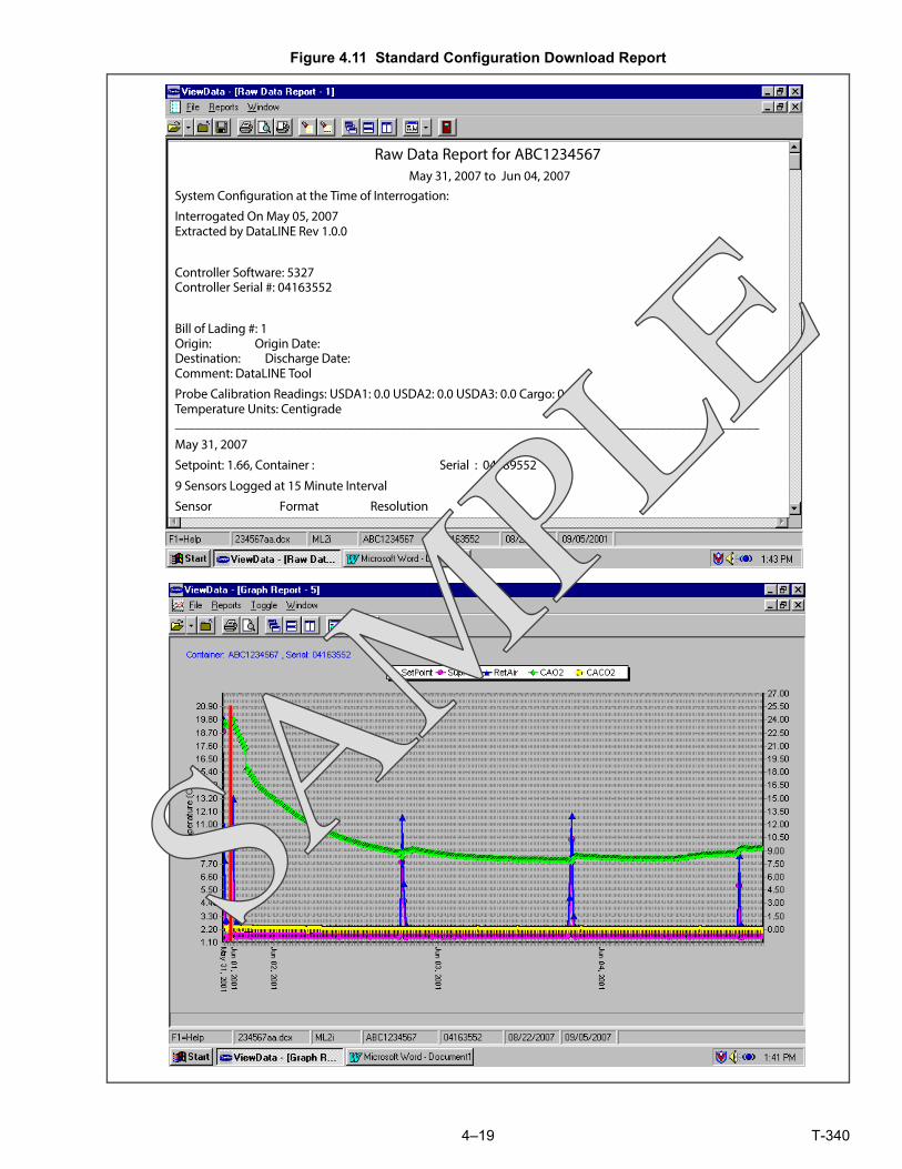
4–19 T-340
Figure 4.11 Standard Configuration Download Report
Raw Data Report for ABC1234567May 31, 2007 to Jun 04, 2007
System Configuration at the Time of Interrogation:
Interrogated On May 05, 2007Extracted by DataLINE Rev 1.0.0
Controller Software: 5327Controller Serial #: 04163552
Bill of Lading #: 1Origin: Origin Date:Destination: Discharge Date:Comment: DataLINE Tool
Probe Calibration Readings: USDA1: 0.0 USDA2: 0.0 USDA3: 0.0 Cargo: 0.0Temperature Units: Centigrade________________________________________________________________________________________
May 31, 2007
Setpoint: 1.66, Container : Serial : 04189552
9 Sensors Logged at 15 Minute Interval
Sensor Format Resolution

T-340 4–20
4.8.6 Sampling Type (dCF05 & dCF06)
Three types of data sampling are available: average, snapshot andUSDA.When configured to average, the aver-age of readings taken every minute over the recording period is recorded. When configured to snapshot, the sen-sor reading at the log interval time is recorded. When USDA is configured, supply and return temperature readingsare averaged and the three USDA probe readings are snapshot.
4.8.7 Alarm Configuration (dCF07 - dCF10)
USDA and cargo probe alarms may be configured to OFF, ON or AUTO.
If a probe alarm is configured to OFF, the alarm for this probe is always disabled.
If a probe alarm is configured to ON, the associated alarm is always enabled.
If the probes are configured to AUTO, they act as a group. This function is designed to assist users who keep theDataCORDER configured for USDA recording, but do not install the probes for every trip. If all the probes are dis-connected, no alarms are activated. As soon as one of the probes is installed, all of the alarms are enabled and theremaining probes that are not installed will give active alarm indications.
4.8.8 DataCORDER Power Up
The DataCORDER may be powered up in any one of four ways:
1. Normal AC power: The DataCORDER is powered up when the unit is turned on via the Stop-Start switch.
2. Controller DC battery pack power: If a battery pack is installed, the DataCORDER will power up for communi-cation when an interrogation cable is plugged into an interrogation receptacle.
3. External DC battery pack power: A 12 volt battery pack may also be plugged into the back of the interroga-tion cable, which is then plugged into an interrogation port. No controller battery pack is required with thismethod.
4. Real Time Clock demand: If the DataCORDER is equipped with a charged battery pack and AC power is notpresent, the DataCORDER will power up when the real time clock indicates that a data recording should takeplace. When the DataCORDER is finished recording, it will power down.
Table 4–3 DataCORDER Standard Configurations
Standard Configuration Description
2 sensors(dCF02=2)
2 thermistor inputs (supply & return)
5 sensors(dCF02=5)
2 thermistor inputs (supply & return)3 USDA thermistor inputs
6 sensors(dCF02=6)
2 thermistor inputs (supply & return)3 USDA thermistor inputs
1 humidity input
9 sensors(dCF02=9)
Not Applicable
6 sensors(dCF02=54)
2 thermistor inputs (supply & return)3 USDA thermistor inputs
1 cargo probe (thermistor input)
7 sensors(dCF02=64)
2 thermistor inputs (supply & return)3 USDA thermistor inputs
1 humidity input1 cargo probe (thermistor input)
10 sensors(dCF02=94)
2 thermistor inputs (supply & return)3 USDA thermistor inputs
1 humidity input1 cargo probe (thermistor input)
3 C.A. inputs (NOT APPLICABLE)

4–21 T-340
During DataCORDER power-up, while using battery-pack power, the controller will perform a hardware voltagecheck on the battery. If the hardware check passes, the controller will energize and perform a software battery volt-age check before DataCORDER logging. If either test fails, the real time clock battery power-up will be disableduntil the next AC power cycle. Further DataCORDER temperature logging will be prohibited until that time.
An alarm will be generated when the battery voltage transitions from good to bad indicating that the battery packneeds recharging. If the alarm condition persists for more than 24 hours on continuous AC power, it indicates thatthe battery pack needs replacement.
4.8.9 Pre-trip Data Recording
The DataCORDER will record the initiation of a Pre-trip test (refer to Section 4.7) and the results of each testincluded in Pre-trip. The data is time-stamped and may be extracted via the Data Retrieval program. Refer to Table4–9 for a description of the data stored in the DataCORDER for each corresponding Pre-trip test.
4.8.10 DataCORDER Communications
Data retrieval from the DataCORDER can be accomplished by using the DataReader, DataLINE, DataBANK Card,or a communications interface module.
NOTEA DataReader, DataLINE, or a communications interface module display of Communication Failed iscaused by faulty data transfer between the DataCORDER and the data retrieval device. Commoncauses include:
1. Bad cable or connection between DataCORDER and data retrieval device.
2. PC communication port(s) unavailable or mis-assigned.
3. Chart Recorder Fuse (FCR) blown.
Configuration identification for the models covered herein may be obtained on the Container Products Group Infor-mation Center by authorized Carrier Transicold Service Centers.
a. DataReader
The Carrier Transicold Data Reader (see Figure 4.12) is a simple to operate hand-held device designed to extractdata from the DataCORDER and upload it to a PC. The DataReader has the ability to store multiple data files.Refer to Data Retrieval manual 62-10629 for a more detailed explanation of the DataReader.
Figure 4.12 DataReader
1. OFF2. ON3. UP Arrow4. RIGHT Arrow
5. ENTER6. Escape7. DOWN Arrow8. LEFT Arrow
- - - - -
DataReader
1 2
3
4
56
7
8
T-340 4–22
b. DataBANK™ Card
The DataBANK™ card is a PCMCIA card that interfaces with the controller through the programming slot and candownload the data at a much faster rate, when compared to the PC or DataReader. Files downloaded to Data-BANK card files are accessible through an Omni PC Card Drive. The files can then be viewed using the DataLINEsoftware.
c. DataLINE
The DataLINE software for a personal computer is supplied on both floppy disks and CD. This software allowsinterrogation, configuration variable assignment, screen view of the data, hard copy report generation, cold treat-ment probe calibration and file management. Refer to Data Retrieval manual 62-10629 for a more detailed expla-nation of the DataLINE interrogation software. The DataLINE manual may be found on the Internet atwww.container.carrier.com.
d. Communications Interface Module
The communications interface module is a slave module, which allows communication with a master central monitor-ing station. The module will respond to communication and return information over the main power line.
With a communications interface module installed, all functions and selectable features that are accessible at theunit may be performed at the master station. Retrieval of all DataCORDER reports may also be performed. Refer tothe master system technical manual for further information.
4.8.11 USDA Cold Treatment
Sustained cold temperature has been employed as an effective post-harvest method for the control of Mediterra-nean and certain other tropical fruit flies. Exposing infested fruit to temperatures of 2.2°C (36°F) or below for spe-cific periods results in the mortality of the various stages of this group of insects.
In response to the demand to replace fumigation with this environmentally sound process, Carrier has integratedCold Treatment capability into its microprocessor system. These units have the ability to maintain supply air tem-perature within one quarter degree Celsius of set point and record minute changes in product temperature withinthe DataCORDER memory, thus meeting USDA criteria. Information on USDA is provided in the following sub-paragraphs.
a. USDA Recording
A special type of recording is used for USDA cold treatment purposes.Cold treatment recording requires threeremote temperature probes be placed at prescribed locations in the cargo. Provision is made to connect theseprobes to the DataCORDER via receptacles located at the rear left-hand side of the unit. Four or five receptaclesare provided. The four 3-pin receptacles are for the probes. The 5-pin receptacle is the rear connection for theInterrogator. The probe receptacles are sized to accept plugs with tricam coupling locking devices. A label on theback panel of the unit shows which receptacle is used for each probe.
The standard DataCORDER report displays the supply and return air temperatures. The cold treatment report dis-plays USDA #1, #2, #3 and the supply and return air temperatures. Cold treatment recording is backed up by a bat-tery so recording can continue if AC power is lost.
b. USDA/ Message Trip Comment
A special feature in DataLINE allows the user to enter a USDA (or other) message in the header of a data report.The maximum message length is 78 characters. Only one message will be recorded per day.
4.8.12 USDA Cold Treatment Procedure
The following is a summary of the steps required to initiate a USDA Cold Treatment:
a. Calibrate the three USDA probes by ice bathing the probes and performing the calibration function with theDataLINE. This calibration procedure determines the probe offsets and stores them in the controller for usein generating the cold treatment report. Refer to the Data Retrieval manual 62-10629 for more details.
b. Pre-cool the container to the treatment temperature or below.
c. Install the DataCORDER module battery pack (if not already installed).
d. Place the three probes. The probes are placed into the pulp of the product (at the locations defined in thefollowing table) as the product is loaded.

4–23 T-340
e. To initiate USDA recording, connect the personal computer and perform the configuration as follows, usingthe DataLINE software:
1. Enter ISO header information.2. Enter a trip comment if desired.3. Configure the DataCORDER for five probes (s, r, P1, P2, P3) (dcf02=5).4. Configure the logging interval for one hour.5. Set the sensor configuration to “USDA.”6. Configure for two byte memory storage format (dcf04=LONG).7. Perform a “trip start.”
4.8.13 DataCORDER Alarms
The alarm display is an independent DataCORDER function. If an operating parameter is outside of the expectedrange or a component does not return the correct values to the DataCORDER, an alarm is generated. The Data-CORDER contains a buffer of up to eight alarms. A listing of the DataCORDER alarms is provided in Table 4–10.Refer to Section 4.8.7 for configuration information.
To display alarm codes:
a. While in the Default Display mode, press the ALT. MODE & ALARMLIST keys. This accesses the Data-CORDER Alarm List Display Mode, which displays any alarms stored in the alarm queue.
b. To scroll to the end of the alarm list, press the UP ARROW. Depressing the DOWN ARROW key will scrollthe list backward.
c. The left display will show “AL#” where # is the alarms number in the queue. The right display will show“AA##,” if the alarm is active, where ## is the alarm number. “IA##,” will show if the alarm is inactive.
d. “END” is displayed to indicate the end of the alarm list if any alarms are active. “CLEAr” is displayed if all thealarms in the list are inactive.
e. If no alarms are active, the alarm queue may be cleared. The exception to this rule is the DataCORDERalarm queue Full alarm (AL91), which does not have to be inactive in order to clear the alarm list. To clearthe alarm list:
1. Press the ALT. MODE & ALARM LIST keys.2. Press the UP/DOWN ARROW key until “CLEAr” is displayed.3. Press the ENTER key. The alarm list will clear and “-----” will be displayed.4. Press the ALARM LIST key. “AL” will show on the left display and “-----” on the right display when there
are no alarms in the list.5. Upon clearing of the alarm queue, the alarm light will be turned off.
4.8.14 ISO Trip Header
DataLINE provides the user with an interface to view/ modify current settings of the ISO trip header through theISO Trip Header screen.
The ISO Trip Header screen is displayed when the user clicks on the “ISO Trip Header” button in the “Trip Func-tions” Group Box on the System Tools screen.
F9 function - Provides the user with a shortcut for manually triggering the refresh operation. Before sending modi-fied parameter values, the user must ensure that a successful connection is established with the controller.
If the connection is established with the DataCORDER, the current contents of the ISO Trip Header from the Data-CORDER will be displayed in each field. If the connection is not established with the DataCORDER, all fields onthe screen will be displayed as “Xs.” If at any time during the display of the ISO Trip Header screen the connectionis not established or is lost, the user is alerted to the status of the connection.
After modifying the values and ensuring a successful connection has been made with the DataCORDER, click on the“Send” button to send the modified parameter values.
The maximum allowed length of the ISO Trip Header is 128 characters. If the user tries to refresh the screen orclose the utility without sending the changes made on the screen to the DataCORDER, the user is alerted with amessage.
Sensor 1 Place in pulp of the product located next to the return air intake.
Sensor 2Place in pulp of the product five feet from the end of the load for 40 foot con-tainers, or three feet from the end of the load for 20 foot containers. This probeshould be placed in a center carton at one-half the height of the load.
Sensor 3Place in pulp of product five feet from the end of the load for 40 foot containersor three feet from the end of the load for 20 foot containers. This probe shouldbe placed in a carton at a side wall at one-half the height of the load.

T-340 4–24
4.9 CONTROLLER CONFIGURATION VARIABLES
NOTEConfiguration numbers not listed are not used in this application. These items may appear when loadingconfiguration software to the controller but changes will not be recognized by the controller programming.
Table 4–4 Controller Configuration Variables
CONFIG NUMBER TITLE DEFAULT OPTION
CnF02 Evaporator Fan Speed dS (Dual) SS (Single)
CnF03 Control Temperature Sensors FOUr duAL
CnF04 Enable Dehumidification On OFF
CnF08 Evaporator Motor Type 1Ph 3Ph
CnF09 Refrigerant Type r134a r744
CnF11 Defrost “Off” Selection noOFF OFF
CnF15 Enable Discharge Temperature Sensor Out In
CnF16 Enable DataCORDER On (Yes) (Not Allowed)
CnF17 Enable Discharge Pressure Sensor Out (No) In (Yes)
CnF18 Heater Type Old (Low Watt) nEW (High Watt)
CnF20 Enable Suction Pressure Sensor Out (No) In (Yes)
CnF22 Economy Mode OFF Std, Full
CnF23 Enable Defrost Interval Save noSAv SAv
CnF24 Enable Long Pre-trip Test Series Auto Auto2, Auto 3
CnF25 Enable Pre-trip Data Recording rSLtS dAtA
CnF26 Heat Lockout Temperature Set to -10C Set to -5C
CnF27 Enable Suction Temperature Sensor Out In
CnF28 Enable Bulb Mode NOr bULb
CnF31 Probe Check SPEC Std
CnF32 Enable Single Evaporator Fan Option 2EF0 (Not Allowed)
CnF33 Enable Snap Freeze OFF SnAP
CnF34 Temperature Unit Display nOth F
CnF37 Electronic Chart Probe rEtUR SUPPL, bOth
CnF41 Enable Low DTT Setting Out In
CnF44 Autoslide Enable Out LO, UP
CnF45 Low Humidity Enabled Out In
CnF46 Quench/liquid Injection Valve Type nO=0=no nC=1=nc
CnF47 Vent Position OFF UP, LOW, CUStOM
CnF49 OEM Reset Option OFF 0-off,1-std, 2-spec, 3-cust
CnF50 Enhanced Bulb Mode Interface 0 0-out, 1-in
CnF51 Timed Defrost Disable 0 0-out, 1-in
CnF52 Oil Return Algorithm 0 0-out, 1-in
CnF53 Water Cool Oil Return Logic 0 0-out, 1-in
CnF55 TXV Boost Relay 0 0-out, 1-in
CnF56 TXV Boost Circuit 0 0-out, 1-in
CnF57 PWM Compressor Control 0 0-out, 1-in
CnF59 Electronic Evaporator Expansion Valve 0 0-out, 1-EC, 2-KE, 3-NA
CnF61 ACT ASC Control Enable 0 0-out, 1-in
CnF62 Extended Temperature Control Enable 0 0-out, 1-in
CnF63 CCPC Pre-trip/Tripstart Default State 0 0-on, 1-off
CnF64 Enable Fan Pulsing Logic 0 0-in, 1-out
CnF66 High Speed Evaporator Fan Option 0 0-off, 1-on
CnF67 Air Heaters 0 0-out, 1-in

4–25 T-340
4.10 CONTROLLER FUNCTION CODES
Table 4–5 Controller Function Codes
Code No.
TITLE DESCRIPTION
Note: If the function is not applicable, the display will read “-----”
Display Only Functions - Cd01 through Cd26 are display only functions.
Display Only Functions
Cd01Digital UnloaderValve Closed (%)
Displays the DUV percent closed. The right display reads 100% when the valve is fully closed. The valve will usually be at 10% on start up of the unit except in very high ambient temperatures.
Cd03Compressor MotorCurrent
The current sensor measures current draw in lines L1 & L2 by all of the high voltage com-ponents. It also measures current draw in compressor motor leg T3. The compressor leg T3 current is displayed.
Cd04
Cd05
Cd06
Line Current,Phase A
Line Current,Phase B
Line Current,Phase C
The current sensor measures current on two legs. The third unmeasured leg is calculated based on a current algorithm. The current measured is used for control and diagnostic purposes. For control processing, the highest of the Phase A and B current values is used for current limiting purposes. For diagnostic processing, the current draws are used to monitor component energization.Whenever a heater or a motor is turned ON or OFF, the current draw increase/reduction for that activity is measured. The current draw is then tested to determine if it falls within the expected range of values for the component. Fail-ure of this test will result in a Pre-trip failure or a control alarm indication.
Cd07 Main Power Voltage The main supply voltage is displayed.
Cd08Main PowerFrequency
The value of the main power frequency is displayed in Hertz. The frequency displayed will be halved if either fuse F1 or F2 is bad (alarm code AL21).
Cd09 Ambient Temperature The ambient sensor reading is displayed.
Cd10Evaporator TemperatureSensor
Evaporator temperature sensor reading is shown on the right display.
Cd11Compressor DischargeTemperature
Compressor discharge temperature sensor reading, using compressor dome tempera-ture, is displayed.
Cd12Compressor SuctionPressure
Reading for evaporator pressure transducer (EPT) is shown on the left display; Press EN-TER at Cd12 to show reading for compressor suction port pressure on right display.
Cd14Compressor DischargePressure
Compressor discharges pressure transducer reading is displayed.
Cd15 Digital Unloader Valve The status of the valve is displayed (Open - Closed).
Cd16Compressor MotorHour Meter/Unit RunTime Hour Meter
This code displays the compressor motor hours. User can view unit run time by pressing the ENTER key while in Cd16. Total hours are recorded in increments of 10 hours (i.e., 3000 hours is displayed as 300).The Compressor Motor Hour Meter display can be reset to 0 by pressing and holding the ENTER key for 5 seconds. The Unit Run Time Hour Meter cannot be reset.
Cd17 Relative Humidity %Humidity sensor reading is displayed. This code displays the relative humidity, as a per-cent value.
Cd18 Software Revision # The software revision number is displayed.
Cd19 Battery Check
This code checks the Controller/DataCORDER battery pack. While the test is running, “btest” will flash on the right display, followed by the result. “PASS” will be displayed for battery voltages greater than 7.0 volts. “FAIL” will be displayed for battery voltages be-tween 4.5 and 7.0 volts, and “-----” will be displayed for battery voltages less than 4.5 volts. After the result is displayed for four seconds, “btest” will again be displayed, and the user may continue to scroll through the various codes.
Cd20 Config/Model #
This code indicates the dash number of the model for which the Controller is configured (i.e., if the unit is a 69NT40-551-100, the display will show “51100”). To display controller configuration database information, press ENTER. Values in “CFYYMMDD” format are displayed if the controller was configured with a configuration card or with a valid OEM serial port configuration update; YYMMDD represents the publication date of the model configuration database.
Cd21 Capacity Mode The mode of operation is displayed (Unloaded - Standard - Economized).
Cd22 Compressor State The status of the compressor is displayed (OFF, On).

T-340 4–26
Cd23 Evaporator Fan Displays the current evaporator fan state (OFF, LOW, HIGH).
Cd25Compressor Run Time Remaining Until Defrost
This code displays the time remaining until the unit goes into defrost (in tenths of an hour). This value is based on the actual accumulated compressor running time.
Cd26Defrost TemperatureSensor Reading
Defrost temperature sensor reading is displayed.
Configurable Functions - Cd27 through Cd37 are user-selectable functions. The operator can change the value of these functions to meet the operational needs of the container.
Cd27Defrost Interval(Hours or Automatic)
This is the desired period of time between defrost cycles. Factory default is 3 hours. Refer to Section 4.3.23 for information on Defrost Interval.CnF11 determines whether the operator will be allowed to chose “OFF” as a defrost in-terval option.CnF64 determines whether the operator will be allowed to choose “PuLS” as a defrost in-terval option. For units operating with “PuLS” selected, defrost interval is determined by the unit temperature setpoint and the Evaporator Fan Pulsing Temperature Setting (Cd60). When the unit temperature setpoint is equal to or less than the Evaporator Fan Pulsing Temperature Setting, the defrost interval is set to 6 hours. Otherwise, the defrost interval is determined using the Automatic Defrost Interval Determination logic. In either case, “PuLS” remains displayed in this function select code.After a new Defrost Interval is selected, the previously selected Interval is used until the next defrost termination, the next time the DTT contacts are OPEN, or the next time power to the control is interrupted. If the previous value or the new value is “OFF”, the newly se-lected value will be used immediately.If any Auto Pretrip sequence is initiated, Cd27 will be set to ‘AUTO’ unless CnF49 (OEM Reset) is set to “Custom” AND CnF64 (Evaporator Fan Pulsing Logic) configuration vari-able is set to IN, in which case Cd27 will be set to “PuLS”.
Cd28Temperature Units(Degrees C orDegrees F)
This code determines the temperature units (C or F) that will be used for all temperature displays. The user selects C or F by selecting function code Cd28 and pushing the EN-TER key. The factory default value is Celsius units. This function code will display “-----” if CnF34 is set to F.
Cd29 Failure Action (Mode)
If all of the control sensors are out of range (alarm code AL26) or there is a probe circuit calibration failure (alarm code AL27), the unit will enter the shutdown state defined by this setting. The user selects one of four possible actions as follows:A - Full Cooling (Compressor is on, economized operation.)b - Partial Cooling (Compressor is on, standard operation.)C - Evaporator Fan Only (Evaporator fans on high speed, not applicable with frozen set points.)d - Full System Shutdown - Factory Default (Shut down every component in the unit.)
Cd30 In-Range Tolerance
The in-range tolerance will determine the temperature band around the set point which will be designated as in-range.For normal temperature control, control temperature is considered in range if it is within setpoint in-range Tolerance. There are four possible values:1 = +/- 0.5°C (+/-0.9°F)2 = +/- 1.0°C (+/-1.8°F)3 = +/- 1.5°C (+/-2.7°F)4 = +/- 2.0°C (+/-3.6°F) - Factory DefaultIf the control temperature is in-range, the green IN-RANGE light will be illuminated.In-range tolerance shall be set to +/- 2.0?C upon activation of dehumidification or bulb mode (Cd33, Cd35, Cd48).When CCPC is actively controlling, in-range tolerance is not considered.“-----” will be displayed whenever Dehumidification or Bulb mode is enabled or when CCPC with six hour re-activation is actively controlling.“-----” will be displayed whenever Frozen Economy Mode is operating.
Cd31Stagger Start Offset Time (Seconds)
The stagger start offset time is the amount of time that the unit will delay at start-up, thus allowing multiple units to stagger their control initiation when all units are powered up to-gether. The eight possible offset values are 0 (Factory Default), 3, 6, 9, 12, 15, 18 or 21 seconds.
Table 4–5 Controller Function Codes
Code No.
TITLE DESCRIPTION

4–27 T-340
Cd32 Current Limit (Amperes)
The current limit is the maximum current draw allowed on any phase at any time. Limiting the unit’s current reduces the load on the main power supply. When desirable, the limit can be lowered. Note, however, that capacity is also reduced. The five values for 460 VAC op-eration are: 15, 17, 19, 21, or 23 amperes. The factory default setting is 21 amperes.
Cd33 Humidity Setpoint
This is the value in percent to which the system will dehumidify or humidify. There are con-figuration variables that determine whether dehumidification/humidification capabilities are installed. In the test mode, the setpoint will be temporarily set to 1%, allowing the test of dehumidification. After 5minutes, the normal setpoint is restored. If unit is configured for HUMIDIFICATION MODE then selection of a setpoint greater than 75% will activate humidification, and a setpoint less than or equal to 75% will activate dehumidification. If the unit is configured for dehumidification only, then the entire setpoint range will apply to dehumidification. If Pretrip is initiated, this value will be set to “OFF” automatically.(Replaced by Cd48 interface if CnF50 Enhanced Bulb Mode Interface is active.)
Cd34 Economy Mode (On-Off)The current state of the economy mode option, “-----”, On, or Off. CnF22 determines whether economy mode offered. Economy mode is a user selectable mode of operation provided for power saving purposes.
Cd35 Bulb Mode
The current state of the bulb mode option, “-----”, nOr, or bULb.(Replaced by Cd48 if CnF50, Enhanced Bulb Mode, is active.)Bulb mode is an extension of dehumidification control (Cd33). If dehumidification (CnF04) is set to “Off,” Cd35 will display “Nor” and the user will be unable to change it. CnF28 de-termines whether the bulb mode selection is offered.After a dehumidification set point has been selected and entered for code Cd33, the user may then change Cd35 to “bulb.” After Bulb Mode has been selected and entered, the user may then utilize function codes Cd36 and Cd37 to make the desired changes.
Cd36Evaporator FanSpeed Select
This is the desired evaporator fan speed for use during the bulb Dehumidification and Hu-midification mode option.(Replaced by Cd48 if CnF50, Enhanced Bulb Mode, is active.)This code is enabled only if in the dehumidification mode (Cd33) and bulb mode (Cd35) has been set to “bulb.” If these conditions are not met, “alt” will be displayed (indicating that the evaporator fans will alternate their speed) and the display cannot be changed.If a dehumidification set point has been selected along with bulb mode then “alt” may be selected for alternating speed, “Lo” for low speed evaporator fan only, or “Hi” for high speed evaporator fan only.If a setting other than “alt” has been selected and bulb mode is deactivated in any manner, then selection reverts back to “alt.”
Cd37Variable DTT Setting(Bulb Mode)
This is the variable defrost termination thermostat setting to be used with the optional bulb mode functionality. This item is only displayed if the bulb mode option is configured on.(Replaced by Cd48 interface if CnF50 Enhanced Bulb Mode Interface is active.)
Display Only Functions - Cd38 through Cd40 are display only functions.
Cd38Secondary SupplyTemperature Sensor
Cd38 will display the current supply recorder sensor (SRS) reading for units configured for four probes. If the unit is configured with a DataCORDER, Cd38 will display “-----.” If the DataCORDER suffers a failure, (AL55) Cd38 will display the supply recorder sensor reading.
Cd39Secondary ReturnTemperature Sensor
Cd39 will display the current return recorder sensor (RRS) reading for units configured for four probes. If the unit is configured with a DataCORDER, Cd39 will display “-----.” If the DataCORDER suffers a failure, (AL55) Cd39 will display the return recorder sensor reading.
Cd40ContainerIdentificationNumber
If a valid container id exists, the default display for Cd40 will be “cd40_XXXXX” where “XXXXX” is the 5th character through the 9th character of the container id. Pressing the En-ter key on Cd40 will display “id_YYYYYYY” where “YYYYYYY” is the 5th character to the 11th character of the container id.If no valid container id exists or the container id is blank, the default display will have Cd40 on the left display and the right display will alternate between “_nEEd” and “___id”. Pressing the enter key while on Cd40 in the state will prompt the Set Id Interface.On start up if the container id is not valid, Cd40 will be brought up on the display for the first minute of power up. This can be left by either entering a container id or leaving the code se-lect normally.Cd40 is configured at commissioning to read a valid container identification number. The reading will not display alpha characters; only the numeric portion of the number will display.
Table 4–5 Controller Function Codes
Code No.
TITLE DESCRIPTION

T-340 4–28
Cd41 Valve Override
SERVICE FUNCTION: This code is used for troubleshooting, and allows manual posi-tioning of the economizer solenoid valve, electronic expansion valve, and digital unloader valve. Provides readings such as: Percent Capacity, EEV, Capacity Mode, LIV and DUV. Refer to Section 7.21 for operating instructions.
Configurable Functions - Cd43 is a user-selectable function. The operator can change the value of this function to meet the operational needs of the container.
Cd43 eAutoFresh Mode
Cd43 is a user selectable mode of operation that allows the opening and closing of a me-chanical air vent door via a stepper motor. These selection modes are as follows:
OFF - Air makeup vent will remain closed.
USER - Allows for manual selection of the setting.
DELAY -The opening of the door is based on selected time, return temperature and flow rate (percent opened).
gASLM - The opening is based percent open and CO2 and O2 selectable limits (LM). This selection is only active if the unit has a CO2 sensor.
TEST / CAL (CO2 sensor option units only) - The door will fully open and close to allow the user to inspect its operation. If CAL is selected, the controller will zero calibrate the CO2 sensor input.
If the unit is not configured with AutoFresh, the Cd43 will display “----”Refer to Section 5.4.3 for description of operational parameters.
Display Only Function - Cd44 is a display only function.
Cd44eAutoFresh Values /CO2 Sensor Status
Code Cd44 displays the eAutoFresh CO2 and O2 values (CO2 and O2) and CO2 and O2 limits (CO2 LIM and O2 LIM), respectively.This function code will be dashed out if not configured for eAutofresh.This function code will be dashed if CO2 sensor is not detected, and a sensor is not ex-pected (didn’t have one previously).This function code will display “ChECK” if a CO2 sensor has not been auto-detected at the most recent power-up and was detected at a previous power-up. If “ChECK” is dis-played and the ENTER key is pressed, “SEnSr” is displayed with the choices of “YES” and “no”:“YES” – sensor should be remembered as detected (present)“no” – sensor should not be remembered as being detected (not present)
Configurable Functions - Cd45 through Cd48 are user-selectable functions. The operator can change the value of these func-tions to meet the operational needs of the container.
Cd45Vent Position Sensor(VPS) Position
Values: 0 to 240 for UPPER / 0 to 225 for LOWERThis function code will be dashed out if not configured for VPS.When configured for VPS, Cd45 displays the current vent position in units of 5 CMH (units displayed as “CM”) or CFM (units displayed as “CF”) depending on the selection of Cd46 (Airflow display units), Cd28 (Metric/Imperial) or the pressing of the deg C/F key.Cd45 will display whenever the control detects movement via the sensor unless AL50 is active. Cd45 will display for 30 seconds, then time out and return to the normal display mode.
Cd46 Airflow Display Units
Selects the airflow units to be displayed by Cd45 if configured for Vent Position Sensor or displayed by “USER/FLO” under Cd43 if configured for Autoslide.CF = Cubic Feet per MinuteCM = Cubic Meters per HourbOth = Displays CF or CM depending on the setting of Cd28 (Metric/Imperial) or the pressing of the degree C/F key.
Cd47Variable EconomyTemperature Setting
The variable temperature “degrees C or degrees F” setting is used with economy mode. Function code is “----” when unit is not configured for economy mode.
Table 4–5 Controller Function Codes
Code No.
TITLE DESCRIPTION
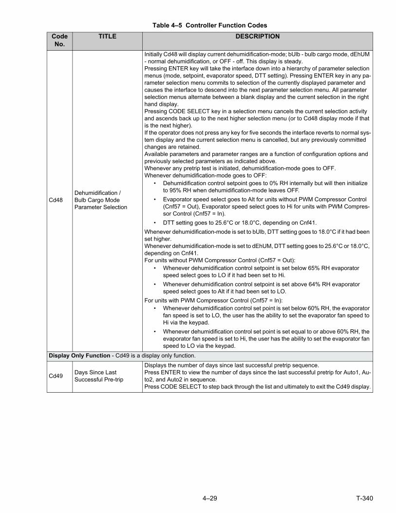
4–29 T-340
Cd48Dehumidification /Bulb Cargo ModeParameter Selection
Initially Cd48 will display current dehumidification-mode; bUlb - bulb cargo mode, dEhUM - normal dehumidification, or OFF - off. This display is steady.Pressing ENTER key will take the interface down into a hierarchy of parameter selection menus (mode, setpoint, evaporator speed, DTT setting). Pressing ENTER key in any pa-rameter selection menu commits to selection of the currently displayed parameter and causes the interface to descend into the next parameter selection menu. All parameter selection menus alternate between a blank display and the current selection in the right hand display.Pressing CODE SELECT key in a selection menu cancels the current selection activity and ascends back up to the next higher selection menu (or to Cd48 display mode if that is the next higher).If the operator does not press any key for five seconds the interface reverts to normal sys-tem display and the current selection menu is cancelled, but any previously committed changes are retained.Available parameters and parameter ranges are a function of configuration options and previously selected parameters as indicated above.Whenever any pretrip test is initiated, dehumidification-mode goes to OFF.Whenever dehumidification-mode goes to OFF:
• Dehumidification control setpoint goes to 0% RH internally but will then initialize to 95% RH when dehumidification-mode leaves OFF.
• Evaporator speed select goes to Alt for units without PWM Compressor Control (Cnf57 = Out), Evaporator speed select goes to Hi for units with PWM Compres-sor Control (Cnf57 = In).
• DTT setting goes to 25.6°C or 18.0°C, depending on Cnf41.
Whenever dehumidification-mode is set to bUlb, DTT setting goes to 18.0°C if it had been set higher.Whenever dehumidification-mode is set to dEhUM, DTT setting goes to 25.6°C or 18.0°C, depending on Cnf41.For units without PWM Compressor Control (Cnf57 = Out):
• Whenever dehumidification control setpoint is set below 65% RH evaporator speed select goes to LO if it had been set to Hi.
• Whenever dehumidification control setpoint is set above 64% RH evaporator speed select goes to Alt if it had been set to LO.
For units with PWM Compressor Control (Cnf57 = In):• Whenever dehumidification control set point is set below 60% RH, the evaporator
fan speed is set to LO, the user has the ability to set the evaporator fan speed to Hi via the keypad.
• Whenever dehumidification control set point is set equal to or above 60% RH, the evaporator fan speed is set to Hi, the user has the ability to set the evaporator fan speed to LO via the keypad.
Display Only Function - Cd49 is a display only function.
Cd49Days Since LastSuccessful Pre-trip
Displays the number of days since last successful pretrip sequence.Press ENTER to view the number of days since the last successful pretrip for Auto1, Au-to2, and Auto2 in sequence.Press CODE SELECT to step back through the list and ultimately to exit the Cd49 display.
Table 4–5 Controller Function Codes
Code No.
TITLE DESCRIPTION

T-340 4–30
Configurable Functions - Cd50 through Cd53 are user-selectable functions. The operator can change the value of these func-tions to meet the operational needs of the container.
Cd50 CCPC Disabled
”OFF” = disabled.”On” = enabled.”SEtPt” = suspended by setpoint too low.”CAHUM” = suspended by CA or humidity control.”ACt” = suspended by ACT active.”FAIL” = all return temperature probe failure for CCPC.”PrtrP” = pretrip active.”C LIM” = suspended by cool limit logic.”PULL” = pulldown active.“ALArM ” = suspended by shutdown alarmPress enter, arrow keys, and then enter to select “OFF” or “On”.If “On” is selected, CCPC operation may be suspended as indicated by one of the sus-pension codes listed above. If CCPC is not “OFF” and is not suspended, “On” will be dis-played.
Cd51Automatic ColdTreatmentParameter Selection
ACT-mode:Cd51 increments of (1 day)_(1hr), Display: default “0_0 ““done” mm-dd this will be display is ACT has completed“ACt” value “On” “OFF” or “----“Display /Select: default “OFF““trEAt” value °C / °F on 0.1 degree increments Display/Select: default “0.0°C““DAyS” value “0 – 99” increments of 1 Display/Select: default “0”“ProbE” value Probe positions ex ’1 2 _ 4’ ’1 _ 3 _’ Display: default “---- ““SPnEW” value °C / °F on 0.1° increments Display/Select: default “10.0°C “Initially Cd51 will display current countdown timer increments of (1 day)_(1hr), default “0_0Pressing ENTER key will take the interface down into a hierarchy of parameter selection menus (act, treat, days, probe and spnew setting).Pressing ENTER key in any of the parameter selection menus commits to selection of the currently displayed parameter and causes the interface to descend into the next param-eter selection menu. All parameter selection menus alternate between a blank display and the current selection in the right hand display.Pressing CODE SELECT key in a selection menu cancels the current selection activity and ascends back up to the next higher selection menu (or to Cd51 display mode if that is the next higher).If the operator does not press any key for five seconds the interface reverts to normal sys-tem display and the current selection menu is cancelled, but any previously committed changes are retained.Available parameters and parameter ranges are a function of configuration options and previously selected parameters as indicated above.Parameter with the exception of “Act” may not be altered if Cd51 is re-entered if “Act” is “On”. When ACT has completed including reaching the new setpoint “done” on the left dis-play and the MONTH DAY of completion on the right display will be displayed as the sec-ond entry in the menu. Turning ACT off clears this entry. This action also resets Cd51 to initial time remaining. ACT must then be turned on to view or modify the additional param-eters.Whenever any auto Pre-trip test or Trip Start is initiated, ACT mode goes to OFF.
Table 4–5 Controller Function Codes
Code No.
TITLE DESCRIPTION

4–31 T-340
Cd53Automatic Set pointChange ModeParameter Selection
ASC-mode:
Cd53 increments of (1 day)_(1hr), Display: default “0_0 “
“done” mm-dd this will be display is ASC has completed
“ASC” value “On” “OFF” Display /Select: default “OFF“
“nSC” value “1 - 6” (This is the value “n” for the subsequent entries).
“SP (n-1)” value °C / °F on 0.1 degree increments Display/Select: default “10.0°C“
“DAY (n-1)” value “1 – 99” increments of 1 Display/Select: default “1“
“SP (n)” value °C / °F on 0.1 degree increments Display/Select: default “10.0°C
Initially Cd53 will display current count down timer increments of (1 day)_(1hr), default “0_0
Pressing ENTER key will take the interface down into a hierarchy of parameter selection menus, (mode, act, treat, days, probe and spnew setting). Pressing ENTER key in any of the parameter selection menus selects the currently displayed parameter and causes the interface to descend into the next parameter selection menu. All parameter selection menus alternate between a blank display and the current selection in the right hand dis-play.
Pressing CODE SELECT key in a selection menu cancels the current selection activity and ascends back up to the next higher selection menu (or to Cd53 display mode if that is the next higher).
If the operator does not press any key for five seconds the interface reverts to normal sys-tem display and the current selection menu is cancelled, but any previously committed changes are retained.
Available parameters and parameter ranges are a function of configuration options and previously selected parameters as indicated above.
Parameter with the exception of “ASC” may not be altered if Cd53 is re-entered if “ASC” is “On”. When ASC has completed including reaching the last setpoint “done” on the left display and the MONTH DAY of completion on the right display will be displayed as the second entry in the menu. Turning ASC off clears this entry. This action also resets Cd53 to initial time remaining. ASC must then be turned on to view or modify the additional pa-rameters.
Whenever any auto pretrip test or Trip Start is initiated, ASC mode goes to OFF.
Display Only Functions - Cd54 through Cd58 are display only functions.
Cd54Suction Port Superheat /Electronic Expansion Valve Status
Reading for evaporator superheat (suction temperature minus suction saturation tem-perature as calculated from suction pressure) is shown on the right display.
Press ENTER at Cd54 to show reading for EEV position (in %) on left display.
Cd55 Discharge Superheat
Cd55 will display discharge superheat (discharge temperature minus discharge satura-tion temperature as calculated from discharge pressure) values in C /F as calculated by the discharge temperature minus the discharge saturation temperature as calculated from discharge pressure. “-----” will be displayed if selection is not valid.
Cd58
Water Pressure Switch / CondenserFan Switch State orOverride Logic State
Cd58 will display “CLOSE” if the WPS or CFS switch contacts are closed or if these op-tions are not installed. “OPEn” is displayed when the WPS or CFS switch contacts are open. When the WPS/CFS Override Logic is “TRUE”, the right display will flash on all units.
NOTE:
1. This CLOSE/OPEn state displayed in this Code Select function only applies to units that have the ability to detect the state of a WPS/CFS. This function should not be relied upon to display the condition of the switch on units that don’t have a WPS/CFS switch connected to ECG2 exclusively.
2. The right display will flash if the WPS/CFS Override Logic is TRUE on all units. This is always the case, whether the unit has a WPS or CFS installed or not.
3. The ability of the WPS/CFS Override Logic to control the condenser fan is limited. It is not possible for this logic to control the fan on units that have the WPS or CFS wired in series with the fan contactor. Units wired in this configuration can indicate that the WPS/CFS Override Logic is active by flashing the right display, however, the wiring will not al-low for control of the condenser fan.
Table 4–5 Controller Function Codes
Code No.
TITLE DESCRIPTION

T-340 4–32
Configurable Functions - Cd59 through Cd61 are user-selectable functions. The operator can change the value of these func-tions to meet the operational needs of the container.
Cd59 Pump Down Logic
Cd59 allows operation of the pump down logic control. The display will flash between “STArT PdN” and “PrESS EnTEr”.
Upon entering Cd59 the operator will be required to acknowledge that they want to initiate the pump down control. The display will flash between “STArT P dN” and “PrESS EnTEr”. Once the decision to continue is confirmed pump down logic will begin, and will take com-plete control of the unit until pump down either succeeds or fails. This operation can not be halted once it begins without power cycling the unit.
After pump down logic has been initiated, the operator will be notified to close the Liquid Line Valve, the display will flash between “CLOSE LLV” and “PrESS EnTEr”. Once com-plete the display will read “P dN” to the left, and the current suction pressure to the right.
If the automatic pump down logic succeeds within 20 minutes, the unit will turn itself off, and the display will notify the operator that pump down is complete by flashing between “P dN DOnE” and “SHUT OFF”. The operator must then shut off the unit.
If the automatic pump down logic does not complete within 20 minutes, the unit will drop out of Cd59 and return to its previous control condition.
Cd60Evaporator FanPulsing TemperatureSetting
Cd60 contains a selectable temperature range used to determine the engagement point of the Evaporator Fan Pulsing logic. Default setting is -18.1°C. The user may change the temperature by pressing enter, then scrolling to the desired temperature using either ar-row key. Press Enter to accept the change. The temperature setting will be retained until either a Pretrip or Trip Start is initiated at which time the temperature will set to the default setting.
Cd61High SpeedEvaporator FanSetting
Cd61 is used to force evaporator fan speed to high while temperature control is being per-formed in the perishable setpoint range. When set to “On”, evaporator fans operate in high speed regardless of any other active option that can control evaporator fan speed.Following a power cycle, the state of the function select code is retained at its state prior to the power cycle. If “On”, this function select code will be set to “OFF” when any trip start occurs or any pretrip test is initiated.“-----” will be displayed if setpoint is in frozen range or if CnF66 is configured OFF.
Table 4–5 Controller Function Codes
Code No.
TITLE DESCRIPTION

4–33 T-340
Figure 4.13 Alarm Troubleshooting Sequence
StartTroubleshooting
Unitconfiguredcorrectly?
PassPre-trip
inspection?
ActiveAlarms?
Correctsoftwareversion?
DidEvaporatorfans start?
Operatingpressuresnormal?
Check PowerSupply
Install LatestSoftwareRevision
Load correctunit
configuration
See alarmdetails &
repair
Correctall faults
Yes
Yes
Yes
Yes
No
Yes
No
Yes
No
No
No
No
CorrectRefrigerant
issue
Unit OK
Yes
No
Refer to CONNECT POWER
Refer to CONNECT POWER
Refer to CONTROLLER SOFTWARE
Refer to Configuration Software (Variables)
Refer to Controller Alarm Indications
Refer to Pre-trip Diagnostics
Refer to REFRIGERATION SYSTEM
SERVICE
Check PowerSupply
Unit doesself test? Section 5.2
Section 4.2
Section 5.2
Section 4.2.1
Section 4.6
Section 7.3
Section 4.7

T-340 4–34
4.11 CONTROLLER ALARM INDICATIONS
Table 4–6 Controller Alarm Indications
Alarm Code Cause Components Troubleshooting Corrective Actions
AL03Loss of Super-heat Control
Superheat has re-mained below 1.66°C (3°F) degrees for five minutes continuously while compressor run-ning.Compressor drawing more than 2.0 amps, compressor pressure ratio is greater than 1.8, and Electronic Ex-pansion Valve (EEV) is at 0% open.
Electronic Expan-sion Valve (EEV)
Check the operation of the EEV using Cd41.
Replace EEV if defec-tive.
Evaporator Tem-perature Sen-sor(s) ETS & ETS1.
Verify accuracy of tem-perature sensors, refer to Sensor Checkout Pro-cedure Section 7.24.
Replace ETS or ETS1 if defective.
Evaporator Fans Confirm fans operating properly.
Replace fan(s) if defec-tive, refer to EVAPORA-TOR FAN MOTOR ASSEMBLY Section 7.15.
AL05Manual Defrost Switch Failure
Controller has detected continuous Manual De-frost Switch activity for five minutes or more.
Keypad Power cycle the unit. Resetting the unit may correct problem, monitor the unit.If the alarm reappears after 5 minutes replace the keypad.
AL06Keypad orKeypad Harness Fail
Controller has detected one of the keypad keys is continuously activity.
Keypad or Har-ness
Power cycle the unit. Resetting the unit may correct problem, monitor the unit.If the alarm reappears replace the keypad and harness.
AL07Fresh Air Vent Open
The VPS is reading greater than 0 CMH while unit is in frozen mode or XtendFRESH active.
Vent Position Sensor (VPS)
Manually reposition vent and confirm using Cd45.Refer to VENT POSI-TION SENSOR SER-VICE Section 7.25.
If unable to obtain zero reading, replace defec-tive VPS.
AL08High Compres-sor Pressure Ratio
Controller detects dis-charge pressure to suction pressure ratio is too high.The controller will at-tempt to correct the sit-uation by restarting the compressor.
Discharge Pres-sure Transducer (DPT)
Confirm accurate DPT pressure readings, refer to MANIFOLD GAUGE SET Section 7.2.
Replace DPT if defec-tive.
AL10CO2 SensorFailure
Alarm 10 is triggered when the CO2 sensor voltage is operating outside of the 0.9 v to 4.7 v range, or if the sensor is out of range.
This is a display alarm and has no associated failure action.
Refer to eAutoFresh manual.
The alarm is triggered off when voltage is within operating range.

4–35 T-340
AL14PhaseSequence De-tect Fault
Controller is unable to determine the correct phase relationship.
N/A Power cycle the unit. Resetting the unit may correct problem, monitor the unit.
Wiring Check unit wiring.Confirm pressure read-ings during start-up; suc-tion pressure should decrease and discharge pressure should in-crease.
Correct wiring.
Current Sensor Check Cd41, right most digit:If display is 3 or 4 check compressor / sensor wir-ing.If display is 5 the current sensor is defective.
Replace current sensor if defective.
AL16CompressorCurrent High
Compressor current draw is over the calcu-lated maximum for 10 minutes.
Current Sensor Compare Cd3 to actual measured current at wire T1-T2 or T3 going to the compressor contactor. If there is a difference, de-termine whether this is caused by current sen-sor or amp clamp tool.
Replace current sensor if defective.
Amperage is in-deed too high.
Confirm supply voltage/frequency is within spec-ification and balanced according to Electrical Data Section 3.3.
Correct power supply.
Operating Condi-tions
Make sure system pres-sures are relevant to op-erating conditions.
Check air flow of con-denser.Check Refrigerant charge, refer to RE-FRIGERATION SYS-TEM SERVICE Section 7.3.
Monitor Unit Alarm is display only the alarm may clear itself during operation.
If alarm remains active or is repetitive replace compressor at next available opportunity, re-fer to COMPRESSOR Service Section 7.8.
Table 4–6 Controller Alarm Indications
Alarm Code Cause Components Troubleshooting Corrective Actions

T-340 4–36
AL17Compressor Pressure Delta Fault
Compressor has at-tempted to start in both directions and fails to generate sufficient pressure differential between SPT and DPT.
N/A Controller will attemptrestart every 20 minutes and deactivate the alarm if successful.
Resume normaloperation.
Discharge Pres-sure Transducer (DPT)
Confirm accurate DPT pressure readings, refer to MANIFOLD GAUGE SET Section 7.2.
Replace DPT if defec-tive.
Suction Pressure Transducer (SPT)
Confirm accurate SPT pressure readings, refer to MANIFOLD GAUGE SET Section 7.2.
Replace SPT if defec-tive.
Monitor Unit Alarm is display only the alarm may clear itself during operation.
If alarm remains active or is repetitive replace compressor at next available opportunity.
AL18DischargePressure High
Discharge pressure is over the maximum for 10 minutes within the last hour.
Restrictions in the refrigeration sys-tem.
Ensure Liquid Line Ser-vice Valve is fully open.
Open Liquid Line Ser-vice Valve as needed.
Filter Drier Check the filter drier, if it is iced up or very cold it indicates that the filter drier needs replacement.
Replace the filter drier if needed, refer to FILTER DRIER Service Section 7.13.
Condenser Fan Check Condenser Fan for proper operation.
Correct as required.
Discharge Pres-sure Transducer (DPT)
Confirm accurate DPT pressure readings, refer to MANIFOLD GAUGE SET Section 7.2.
Replace DPT if defec-tive.
Non-condens-ables in the refrig-eration system.
With the unit off allow system to stabilize to ambient temperature.Check system pressure against PT Chart for 134a, refer to Table 7–5.
Correct as required, re-fer to Refrigerant Charge Section 7.7.1.
Refrigerant Check refrigerant level. Correct as required, re-fer to Refrigerant Charge Section 7.7.1.
Table 4–6 Controller Alarm Indications
Alarm Code Cause Components Troubleshooting Corrective Actions

4–37 T-340
AL19DischargeTemperature High
Discharge temperature exceeds 135°C (275°F) for 10 minutes within the last hour.
Restrictions in the refrigeration sys-tem.
Ensure the Discharge Service Valve is fully open.
Open the Discharge Ser-vice Valve as needed.
Check the unit for air flow restrictions.
Clean or remove any de-bris from coils.
Non-condens-ables in the refrig-eration system.
With the unit off allow system to stabilize to ambient temperature.Check system pressure against PT Chart for 134a, refer to Table 7–5.
Correct as required, re-fer to Refrigerant Charge Section 7.7.1.
Additional Alarms such as AL16, AL24.
Check compressoroperation.
If the alarm persists, it may indicate a failing compressor, replace the compressor, refer to COMPRESSOR Ser-vice Section 7.8.
AL20ControlContactor Fuse (F3)
Control power fuse (F3A or F3B) is open.
Check F3A, if the fuse is open:
Check PA, PB, CH coils for short to ground, if short is found:
Replace the defective coil.Replace the fuse.
Check F3B, if the fuse is open:
Check ESV coil resis-tance at TP7 to TP9, if short to ground, or if re-sistance is less than 4 ohms, coil is defective.Check CF, ES, EF, HR coils for short to ground, if short is found, coil is defective.
Replace the defective coil.Replace the fuse.
Check Voltage at QC1:
If voltage is present, it in-dicates a defective mi-croprocessor.
Refer to Controller Ser-vice Section 7.23.
AL21Control Circuit Fuse (F1/F2)
One of the 18 VAC controller fuses (F1/F2) is open. Refer to Cd08.
System Sensors Check system sensors for short to ground.
Replace defective sen-sor(s).
Wiring Check wiring for short to ground.
Repair as needed.
Controller Controller may have an internal short.
Replace controller, refer to Controller Service Section 7.23.
AL22Evaporator IP
Evaporator motor inter-nal protector (IP) is open.
Evaporator Motor Shut down unit, discon-nect power, & check Evaporator Motor IP at plug connection pins 4 & 6.
Replace defective evap-orator fan motor, refer to EVAPORATOR FAN MOTOR Service Sec-tion 7.15.
AL23Loss of Phase B
Controller fails to de-tect current draw.
Incoming Power Check incoming power source.
Correct power source as required.
AL24Compressor IP
Compressor internal protector (IP) is open.
Compressor Shut down unit discon-nect power, & check re-sistance of compressor windings at contactor T1-T2, T2-T3.
Monitor unit, if alarm re-mains active or is repeti-tive replace the compressor at the next available opportunity, re-fer to COMPRESSOR Service Section 7.8.
Table 4–6 Controller Alarm Indications
Alarm Code Cause Components Troubleshooting Corrective Actions

T-340 4–38
AL25Condenser IP
Condenser fan motor internal protector (IP) is open.
Insufficient Air Flow
Shut down unit and check condenser fan for obstructions.
Remove obstructions.
Condenser Fan Motor
Shut down unit, discon-nect power, & check Condenser Fan Motor IP at plug connection pins 1 & 2.
Replace defective con-denser fan motor, refer to Condenser Fan Motor Assembly Service Sec-tion 7.11.
AL26All Sensors Fail-ure:Supply/Return Probes
Sensors out of range. All sensors de-tected as out of range
Perform Pre-trip P5: If P5 passes, no further action is required.
If P5 fails, replace the defective sensor as de-termined by P5, refer to TEMPERATURE SEN-SOR Service Section 7.24.
AL27Analog to Digital Accuracy Fail-ure
Controller AD convert-er faulty.
Controller Power cycle the unit. If the alarm persists, it indi-cates a defective micro-processor.
Replace defective micro-processor, refer to Con-troller Service Section 7.23.
AL28Low Suction Pressure
Suction pressure too low for normal opera-tion.
N/A Power cycle the unit. Resetting the unit may correct problem, monitor the unit.
Suction Pressure Transducer (SPT)
Confirm accurate SPT pressure readings, refer to MANIFOLD GAUGE SET Section 7.2.
Replace SPT if defec-tive.
Discharge Pres-sure Transducer (DPT)
Confirm accurate DPT pressure readings, refer to MANIFOLD GAUGE SET Section 7.2.
Replace DPT if defec-tive.
AL29AutoFreshFailure
Alarm 29 is triggered if CO2 or O2 level is out-side of the limit range and the vent position is at 100% for longer than 90 minutes.
Alarm LED will be activated and user intervention is re-quired.
Refer to eAutoFresh manual.
The alarm is triggered off when atmospheric con-ditions are within limit settings.
AL50Air Vent Position Sensor (VPS)
VPS Sensor out of range.
Vent Position Sensor (VPS)
Make sure VPS is se-cure.
Manually tighten panel.
If the alarm persists, re-place the sensor or the assembly.
Replace VPS.
AL51EEPROM Fail-ure
Controller MemoryFailure
Controller Pressing the ENTER key when “CLEAr” is dis-played will result in an at-tempt to clear the alarm.
If action is successful (all alarms are inactive), alarm 51 will be reset.
Power cycle the unit. If the alarm persists, it indi-cates defective controller memory.
Replace defective con-troller, refer to Controller Service Section 7.23.
Table 4–6 Controller Alarm Indications
Alarm Code Cause Components Troubleshooting Corrective Actions

4–39 T-340
AL52EEPROM Alarm List Full
Alarm list queue is full Active Alarms Repair any alarms in the queue that are active. In-dicated by “AA”.
Clear alarms, refer to CONTROLLER ALARMS Section 4.6.
AL53Battery Pack Failure
Battery voltage low Battery If this alarm occurs on start up, allow a unit fit-ted with rechargeable batteries to operate for up to 24 hours to charge rechargeable batteries sufficiently. Once fully charged, the alarm will deactivate.
To clear the alarm press ENTER and ALT simul-taneously at the startup of Cd19 (Battery Check).If alarm persists, replace the battery pack, refer to Section 7.23.5 Battery Replacement.
AL54Primary Supply Sensor (STS)
Invalid Supply Tem-perature Sensor (STS) reading.
Supply Tempera-ture Sensor (STS)
Perform Pre-trip P5: If P5 passes, no further action is required.
If P5 fails, replace the defective sensor as de-termined by P5, refer to TEMPERATURE SEN-SOR Service Section 7.24.
AL56Primary Return Sensor (RTS)
Invalid Return Tem-perature Sensor (RTS) reading.
Return Tempera-ture Sensor (RTS)
Perform Pre-trip P5: If P5 passes, no further action is required.
If P5 fails, replace the defective sensor as de-termined by P5, refer to TEMPERATURE SEN-SOR Service Section 7.24.
AL57Ambient Sensor (AMBS)
Invalid Ambient Tem-perature Sensor (AMBS) reading.
Ambient Tem-perature Sensor (AMBS)
Test the AMBS, refer to Sensor Checkout Proce-dure Section 7.24.1.
Replace AMBS if defec-tive, refer to TEMPERA-TURE SENSOR Service Section 7.24.
AL58Compressor High Pressure Safety (HPS)
High pressure safety switch remains open for at least one minute.
High Pressure Switch (HPS)
Test the HPS; refer to Checking High Pressure Switch, Section 7.9.1.
Replace HPS if defec-tive, refer to Sensor Re-placement, Section 7.24.
Refrigeration Sys-tem
Check unit for air flow re-strictions.
Clean or remove any de-bris from coils.
AL59Heater Termina-tion Thermostat (HTT)
Heat Termination Ther-mostat (HTT) is open.
Heat Termination Thermostat (HTT)
Check for 24 volts at test point TP10, if no voltage at TP10 after unit has reached set point HTT is open.
Replace HTT if defec-tive, refer to Sensor Re-placement Section 7.24.2.
AL60Defrost Tem-perature Sensor (DTS)
Failure of the Defrost Temperature Sensor (DTS) to open.
Defrost Tempera-ture Sensor (DTS)
Test the DTS; refer to Sensor Checkout Proce-dure Section 7.24.1.
Replace the DTS if de-fective, refer to Sensor Replacement Section 7.24.2.
Table 4–6 Controller Alarm Indications
Alarm Code Cause Components Troubleshooting Corrective Actions
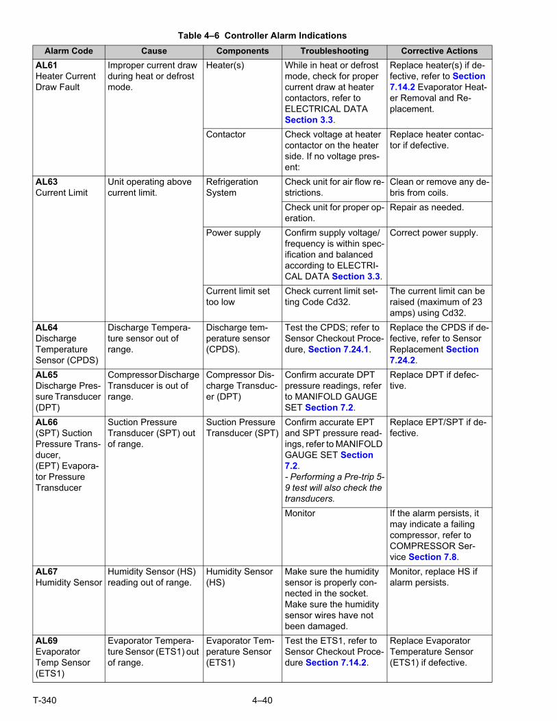
T-340 4–40
AL61Heater Current Draw Fault
Improper current draw during heat or defrost mode.
Heater(s) While in heat or defrost mode, check for proper current draw at heater contactors, refer to ELECTRICAL DATA Section 3.3.
Replace heater(s) if de-fective, refer to Section 7.14.2 Evaporator Heat-er Removal and Re-placement.
Contactor Check voltage at heater contactor on the heater side. If no voltage pres-ent:
Replace heater contac-tor if defective.
AL63Current Limit
Unit operating above current limit.
RefrigerationSystem
Check unit for air flow re-strictions.
Clean or remove any de-bris from coils.
Check unit for proper op-eration.
Repair as needed.
Power supply Confirm supply voltage/frequency is within spec-ification and balanced according to ELECTRI-CAL DATA Section 3.3.
Correct power supply.
Current limit set too low
Check current limit set-ting Code Cd32.
The current limit can be raised (maximum of 23 amps) using Cd32.
AL64DischargeTemperature Sensor (CPDS)
Discharge Tempera-ture sensor out of range.
Discharge tem-perature sensor (CPDS).
Test the CPDS; refer to Sensor Checkout Proce-dure, Section 7.24.1.
Replace the CPDS if de-fective, refer to Sensor Replacement Section 7.24.2.
AL65Discharge Pres-sure Transducer (DPT)
Compressor Discharge Transducer is out of range.
Compressor Dis-charge Transduc-er (DPT)
Confirm accurate DPT pressure readings, refer to MANIFOLD GAUGE SET Section 7.2.
Replace DPT if defec-tive.
AL66(SPT) Suction Pressure Trans-ducer,(EPT) Evapora-tor Pressure Transducer
Suction Pressure Transducer (SPT) out of range.
Suction Pressure Transducer (SPT)
Confirm accurate EPT and SPT pressure read-ings, refer to MANIFOLD GAUGE SET Section 7.2.- Performing a Pre-trip 5-9 test will also check the transducers.
Replace EPT/SPT if de-fective.
Monitor If the alarm persists, it may indicate a failing compressor, refer to COMPRESSOR Ser-vice Section 7.8.
AL67Humidity Sensor
Humidity Sensor (HS) reading out of range.
Humidity Sensor (HS)
Make sure the humidity sensor is properly con-nected in the socket.Make sure the humidity sensor wires have not been damaged.
Monitor, replace HS if alarm persists.
AL69Evaporator Temp Sensor (ETS1)
Evaporator Tempera-ture Sensor (ETS1) out of range.
Evaporator Tem-perature Sensor (ETS1)
Test the ETS1, refer to Sensor Checkout Proce-dure Section 7.14.2.
Replace Evaporator Temperature Sensor (ETS1) if defective.
Table 4–6 Controller Alarm Indications
Alarm Code Cause Components Troubleshooting Corrective Actions

4–41 T-340
AL70Secondary Sup-ply Sensor (SRS)
Secondary Supply Sensor (SRS) is out of range.
Secondary Sup-ply Sensor (SRS)
Perform Pre-trip P5: If P5 passes, no further action is required.
If P5 fails, replace the defective sensor as de-termined by P5, refer to TEMPERATURE SEN-SOR Service Section 7.24.
AL71SecondaryReturn Sensor (RRS)
Secondary Return Sensor (RRS) is out of range.
Secondary Return Sensor (RRS)
Perform Pre-trip P5: If P5 passes, no further action is required.
If P5 fails, replace the defective sensor as de-termined by P5, refer to TEMPERATURE SEN-SOR Service Section 7.24.
AL72Control Temp Out of Range
After the unit goes in-range for 30 minutes then out of range for a continuous 120 min-utes.
RefrigerationSystem
Ensure unit is operating correctly.
Power cycle unit.Control Temperature is in In-range.Any Pre-trip mode, re-sets the timers.
NOTEIf the controller is configured for four probes without a DataCORDER, the DataCORDER alarms
AL70 and AL71 will be processed as Controller alarms AL70 and AL71. Refer to Table 4–10.
Table 4–6 Controller Alarm Indications
Alarm Code Cause Components Troubleshooting Corrective Actions

T-340 4–42
ERR #InternalMicroprocessorFailure
The controller performs self-check routines. If an internal failure occurs, an “ERR” alarm will appear on the display. This is an indication the con-troller needs to be replaced.
ERROR DESCRIPTION
ERR 0-RAM fail-ure
Indicates that the controller working memory has failed.
ERR 1-Program Memory failure
Indicates a problem with the controller program.
ERR 2-Watchdog time-out
The controller program has entered a mode whereby the controller program has stopped executing.
ERR 3-N/A N/A
ERR 4-N/A N/A
ERR 5-A-D failure The controller’s Analog to Digital (A-D) converter has failed.
ERR 6-IO Board failure
Internal program/update failure.
ERR 7-Controller failure
Internal version/firmware incompatible.
ERR 8-Data-CORDER failure
Internal DataCORDER memory failure.
ERR 9-Controller failure
Internal controller memory failure.
In the event that a failure occurs and the display cannot be updated, the status LED will indicate the appropriate ERR code using Morse code as shown below.
EntrStPt
Enter Set point (Press Arrow & Enter)
The controller is prompting the operator to enter a set point.
LO Low Main Voltage (Function Codes Cd27-38 disabled and NO alarm stored.)
This message will be alternately displayed with the set point whenever the supply voltage is less than 75% of its proper value.
Table 4–6 Controller Alarm Indications
Alarm Code Cause Components Troubleshooting Corrective Actions

4–43 T-340
4.12 CONTROLLER PRE- TRIP TEST CODES
Table 4–7 Controller Pre-trip Test Codes
NOTE“Auto” or “Auto1” menu includes the: P0, P1, P2, P3, P4, P5, P6 and rSLts. “Auto2” menu includes P0, P1, P2,
P3, P4, P5, P6, P7, P8, P9, P10 and rSLts. “Auto3” menu includes P0, P1, P2, P3, P4, P5, P6, P7 and P8.
P0-0
Pre-Trip Initiated:Configuration Display, Indi-cator Lamps, LEDs, and Displays
Container identifier code, Cd18 Software Revision Number, Cd20 Con-tainer Unit Model Number, & configuration database identifier CFM-MYYDD are displayed in sequence.Next the unit will indicate the presence or non-presence of an RMU ac-cording to whether any RMU inquiry messages have been received since the unit was booted.Units equipped with Autoslide Enabled (Cnf44) will cause the vent to seek to its closed position, followed by two sequences of opening to 100% and returning to the closed position. No other autoslide mode of operation will be available until the two cycles of opening and closing have completed.Since the system cannot recognize lights and display failures, there are no test codes or results associated with this phase of Pretrip. To know if the test passes the operator must observe that the LCD display ele-ments and the indicator lights behave as described below.
P1 Tests - Heaters Current Draw: Heater is turned on, then off. Current draw must fall within specifiedrange. No other system components will change state during this test.
P1-0 Heaters Turned On
Heater starts in the off condition, current draw is measured, and then theheater is turned on. After 15 seconds, the current draw is measuredagain. The change in current draw is then recorded.Test passes if the change in current draw test is in the range specified.
P1-1 Heaters Turned Off
Heater starts in the off condition, current draw is measured, and then theheater is turned on. After 15 seconds, the current draw is measuredagain. The change in current draw is then recorded.Test passes if the change in current draw test is in the range specified.
P2 Tests - Condenser Fan Current Draw: Condenser fan is turned on, then off. Current draw must fallwithin specified range. No other system components will change state during this test. If the Water Pres-sure Switch is open this test will be skipped.
P2-0 Condenser Fan On
Condenser fan starts in the off condition, current draw is measured, andcondenser fan is then turned on. After 15 seconds the current draw ismeasured again. The change in current draw is then recorded.Test passes if change in current draw test is in the specified range.
P2-1 Condenser Fan OffCondenser fan is then turned off. After 10 seconds the current draw ismeasured. The change in current draw is then recorded.Test passes if change in current draw test is in the specified range.
P3 Tests - Low Speed Evaporator Fan Current Draw: The system must be equipped with a low speedevaporator fan, as determined by CnF02, the Evaporator Fan Speed Select configuration variable. Lowspeed evaporator fan is turned on, then off. Current draw must fall within specified range. No other sys-tem components will change state during this test.
NOTE
If unit configured for single evaporator fan operation and either AL11 or AL12 is active at the start ofeither test, then the test will fail immediately. If AL11 or AL12 become active during the test, then thetest will fail upon conclusion of the test.
P3-0Low Speed Evaporator FanMotors On
High speed evaporator fans will be turned on for 20 seconds, the fanswill be turned off for 4 seconds, current draw is measured, and then thelow speed evaporator fans are turned on. After 60 seconds the currentdraw is measured again. The change in current draw is then recorded.Test passes if change in current draw test is in the specified range.

T-340 4–44
P3-1Low Speed Evaporator FanMotors Off
Low speed evaporator fans are then turned off. After 10 seconds thecurrent draw is measured. The change in current draw is then recorded.Test passes if change in current draw test is in the specified range.
P4 Tests - High Speed Evaporator Fans Current Draw: High speed evaporator fans are turned on,then off. Current draw must fall within specified range and measured current changes must exceed spec-ified ratios. No other system components will change state during this test.
NOTE
If unit configured for single evaporator fan operation and either AL11 or AL12 is active at the start ofeither test, then the test will fail immediately. If AL11 or AL12 become active during the test, then thetest will fail upon conclusion of the test.
P4-0High Speed Evaporator Fan Motors On
Evaporator fans start in the off condition, current draw is measured,then high speed evaporator fans will be turned on. After 60 seconds thecurrent draw is measured again. The change in current draw is then re-corded.Test passes if change in current draw in the specified range AND mea-sured current changes exceed specified ratios.If the three phase motors are configured IN, the change ratio test isskipped.
P4-1High Speed Evaporator Fan Motors Off
High speed evaporator fans are then turned off. After 10 seconds thecurrent draw is measured. The change in current draw is then recorded.Test passes if change in current draw test is in the specified range.
P5 Tests - Air Stream Temperature Sensor Tests: Tests the validity of the Air Stream TemperatureSensors.
P5-0 Supply/Return Probe Test
The High Speed Evaporator Fan is turned on and run for eight minutes,with all other outputs de-energized. A temperature comparison is madebetween the return and supply probes.Test passes if temperature comparison falls within the specified range.
NOTE
If this test fails, “P5-0” and “FAIL” will be displayed. If bothProbe tests (this test and the PRIMARY/SECONDARY) pass,display will read “P5” “PASS.”
P5-1 Supply Probe Test
This test if for units equipped with secondary supply probe only.The temperature difference between primary supply probe and second-ary supply probe is compared.Test passes if temperature comparison falls within the specified range.
NOTE
If this test fails, “P5-1” and “FAIL” will be displayed. If bothProbe tests (this and the SUPPLY/RETURN TEST) pass,because of the multiple tests, the display will read “P5” “PASS.”
P5-2 Return Probe Test
For units equipped with secondary return probe only.The temperature difference between return temperature sensor (RTS)and return temperature sensor (RRS) probe is compared.Test passes if temperature comparison falls within the specified range.
NOTES
1. If this test fails, “P5-2” and “FAIL” will be displayed. If bothProbe tests (this test and the SUPPLY/RETURN) pass, becauseof the multiple tests, the display will read “P 5,” “PASS.”
2. The results of Pre-trip tests 5-0, 5-1 and 5-2 will be used toactivate or clear control probe alarms.
Table 4–7 Controller Pre-trip Test Codes

4–45 T-340
P5-3Evaporator Fan Direction Test
If configured for three phase evaporator fan motors:With evaporator fan running on high speed, measure the temperaturedifference between the primary supply and primary return probes. Turnthe heaters on for 60 seconds then measure the temperature differencebetween the primary supply and primary return probes for up to 120 ad-ditional seconds.This is a Pass/Fail test. The test passes if differential of STS is 0.25°Chigher than RTS.Test P5-0 must pass before this test is run.
P5-7Primary vs. Secondary Evaporator Temperature Sensor Test
This is a Pass/Fail test of the primary evaporator temperature sensor(ETS1) and secondary evaporator temperature sensor (ETS2).Test passes if secondary evaporator temperature sensor (ETS2) iswithin +/- 0.5°C of the primary evaporator temperature sensor (ETS1).
P5-8Primary Evaporator Pres-sure Transducer Test
This is a Pass/Fail test of the Primary Evaporator Pressure Transducer.Test passes if suction pressure transducer (SPT) is within +/- 0 psi ofsaturation pressure at current evaporator temperature. Also passes ifSPT is within +/- 1 psi of discharge pressure 6 hours after a power inter-ruption.Test P5-7 must pass before this test is run.
P5-9Suction (Evaporator) Pres-sure Transducer Test
Units equipped with a secondary Evaporator pressure transducer.Test passes if suction pressure transducer (SPT) is within +/- 1.5 psi ofthe evaporator pressure transducer (EPT).Test P5-8 must pass before this test is run.
P5-10Humidity Sensor Controller Configuration Verification Test
This is a Pass/Fail/Skip test of the humidity sensor configuration.Test passes if the controller configuration has humidity sensor in.Test fails if the controller configuration has humidity sensor out and Voutis greater than 0.20 Volts for the humidity sensor.Test is skipped if the controller configuration has the humidity sensorout and Vout is less than 0.20 Volts.Test P5-9 must pass before this test is run.
P5-11Humidity Sensor Installa-tion Verification Test
This is a Pass/Fail test of humidity sensor installation (sensor is present).Test passes if Vout is greater than 0.20 Volts for the humidity sensor.Test fails if Vout is less than 0.20 Volts for the humidity sensor.Test P5-10 must pass before this test is run.
P5-12Humidity Sensor Range Check Test
This is a Pass/Fail test of the Humidity Sensor Range.Test passes if Vout for the humidity sensor is between 0.33 Volts and 4Volts.Test fails if Vout is outside of this range.Test P5-11 must pass before this test is run.
P6 Tests - Refrigerant Probes, Compressor and Refrigerant Valves: Pass/Fail testing is performed forthe compressor, EEV, DUV, LIV (if equipped), ESV, and the refrigerant pressure and temperature sensors.
P6-0 Discharge Thermistor Test If Alarm 64 is active the test fails. Otherwise, the test passes.
P6-1 Suction Thermistor TestIf the Suction Temperature Sensor (CPSS) both is configured ON andis invalid, the test fails. Otherwise the test passes.
P6-2Discharge Pressure Sen-sor Test
If Alarm 65 is active any time during the first 45 second period, the testfails. Otherwise, the test passes.
P6-3Suction Pressure Sensor Test
If Alarm 66 is active the test fails. Otherwise the test passes.
P6-4Compressor Current Draw Test
Compressor current is tested before and 10 seconds after start up. Ifcurrent does not increase, the test fails. P6-7 is run at the end of P6-4.If this test fails, P6-6 is skipped.
Table 4–7 Controller Pre-trip Test Codes

T-340 4–46
P6-5 Compressor Leak Test
Pre-trip P6-5 ensures that the compressor holds pressure. After com-pressor pump up and pump down, the compressor is turned off for 62seconds. When suction side pressure holds (less than 8 psi rise) for 10seconds, P6-5 passes, otherwise the Compressor Leak Test fails.
NOTE
P6-6 through P6-10 are conducted by changing status of each valve and comparing suction pressurechange and/or compressor current change with predetermined values. Tests will cause compressor andcondenser fans to cycle on and off as needed to generate the pressure required for individual Pre-tripsub tests. The compressor will start in order to build discharge pressure, followed by compressor pumpdown sequence. At the conclusion of compressor pump down sequence, the compressor will shut downand the valve test will start.
P6-6 Economizer Valve TestPasses if suction pressure increases a minimum of 4 psia when thevalve opens for 15 seconds.
P6-7 Digital Unloader Valve TestPasses if pressure and current changes are within 3 seconds of DUVswitch signal and either the pressure change or the current drawchange is above 5 psi or above 1.5A, respectively.
P6-9 Liquid Injection Valve Test(If equipped) Test passes if change of suction pressure is greater than4 psia when the valve opens for 10 seconds. Otherwise, it fails.
P6-10Electronic Expansion Valve Test
The test records the suction pressure during the open valve positionand passes if the suction pressure increase is above 3 psi when thevalve opens for 10 seconds.
NOTE
P7-0 & P8 are included with “Auto 2 & Auto 3” only. P9-0 through P10 are included with “Auto2” only.
P7 Tests - High Pressure Tests: Unit is run at full capacity without condenser fan running to make surethat the HPS opens and closes properly.
Table 4–7 Controller Pre-trip Test Codes

4–47 T-340
P7-0High Pressure Switch (HPS) Opening Test
Test is skipped if sensed ambient temperature is less than 7.2°C (45°F),return air temperature is less than -17.8°C (0°F), or the water pressureswitch is open.With the unit running, the condenser fan is turned off and a 900 second(15 minute) timer is started. The right display shows Discharge Pres-sure if the sensor is configured and valid, else Discharge Temperature.The unit needs to disable Discharge Pressure limit and enable CurrentLimit checks.The test fails immediately if:
-Ambient Temperature Sensor invalid-Composite Return Temperature Sensor invalid-HPS is open
The test fails if:-HPS fails to open before 900 seconds total test time.-Evaporator or Compressor IP Alarm.-Calculated Dome Temperature exceeds 137.78°C (280°F).-Discharge pressure exceeds 370 psig.-Compressor Current exceeds limits
The test passes if HPS opens within the 15 minute time limit.
P7-1High Pressure Switch (HPS) Closing Test
If return temperature greater than -2.4°C, set setpoint to -5.0°C, else setsetpoint to -30°C. Restart unit according to normal startup logic. Rununit normally for 120 seconds.The test passes if the high pressure switch closes within 75 seconds af-ter end of Test 7-0, else the test fails.Test P7-0 must pass for this test to execute.
P8 Tests - Perishable Mode Tests: Pretrip tests P7-0 and P7-1 must have passed or have beenskipped for these tests to execute.
P8-0 Perishable Mode Test
If the control temperature is below 15.6°C, the setpoint is changed to15.6°C, and a 180 Minute timer is started. The control will then beplaced in the equivalent of normal heating. If the control temperature isabove 15.6°C. at the start of the test, then the test proceeds immediate-ly to test 8-1. While in test 8-0 the right display will show the value of thecontrol temperature.
The test fails if the 180 Minute timer expires before the control tempera-ture reaches setpoint - 0.3°C. If the test fails, it will not auto-repeat.There is no pass display for this test. Once the control temperaturereaches setpoint, the test proceeds to test 8-1.
P8-1Perishable Mode Pull Down Test / eAutofresh CO2 Sensor Calibration
Control temperature must be at least 15.6°C (60°F).
The set point is changed to 0°C (32°F), and a 180-minute timer is start-ed. The left display will read “P8-1,” the right display will show the supplyair temperature. The unit will then start to pull down the temperature tothe 0°C set point.
The test passes if the container temperature reaches set point beforethe 180-minute timer expires.
On units where the CO2 Sensor Status indicates that a CO2 sensor ispresent, calibration of the CO2 sensor will be attempted during P8-1.Once P8-1 begins, calibration will be attempted when the supply tem-perature goes below 5°C. If the CO2 sensor voltage reads within the0.95 <>1.15Vdc range before the end of P8-1, the sensor will be cali-brated by holding the CO2 zero line low for 4 seconds. Once calibrationis performed, the sensor voltage will be verified to make sure it is in the0.95 to 1.05 Vdc range. If the voltage is not within this range, CO2 sen-sor calibration fails.
Table 4–7 Controller Pre-trip Test Codes

T-340 4–48
P8-2Perishable Mode Maintain Temperature Test
Test P8-1 must pass for P8-2 to execute.
A fifteen minute timer is started, and the system will attempt to minimizecontrol temperature error (supply temperature minus setpoint) until thetimer expires. The control temperature will be sampled each minutestarting at the beginning of P8-2.
During P8-2, the left display will read “P8-2,” and the right display willshow the supply air temperature.
When the test is completed, the average control temperature error willbe compared to the pass/fail criteria.
Test passes if the average temperature error is within +/- 1.0°C.
Test fails if the average temperature error is greater than +/- 1.0°C, or ifthe DataCORDER supply temperature probe is invalid. If the test fails,the control probe temperature will be recorded as -50.0°C.
P9 Test - DTT Close and Open Test: The DTT in this control is not a physical device, with actual metal-lic contacts, it is a software function that acts similar to a thermostat. Using various temperature inputs,the DTT function determines whether a thermostat mounted on the Evaporator Coil would have OPEN orCLOSED contacts. Primarily, the DTT function operates based on the temperature reading from theDefrost Termination Sensor.
P9-0 DTT Closed and Open Test
During P9-0 the defrost temperature sensor (DTS) reading will be dis-played on the left display. The right display will show the supply air tem-perature.The unit will run FULL COOL for 30 minutes maximum until the DTT isconsidered closed. This step may not have to be executed. Once theDTT is considered closed, the unit simulates defrost by running theheaters for up to two hours, or until the DTT is considered open.
Test fails if:
The DTT is not considered closed after the 30 minutes of fullcooling.
HTT opens when DTT is considered closed or if return air tem-perature rises above 248°C (120°F).
Test passes if the DTT is considered open within the 2 hour heat cycletime limit.
P10 Tests - Frozen Mode Tests:
P10-0 Frozen Mode Heat Test
If the container temperature is below 7.2°C, the setpoint is changed to7.2°C, and a 180 Minute timer is started. The control will then be placedin the equivalent of normal heating. If the container temperature isabove 7.2°C. at the start of the test, then the test proceeds immediatelyto test 10-1. During this test, the control temperature will be shown onthe right display.The test fails if the 180 Minute timer expires before the control tempera-ture reaches setpoint - 0.3°C. If the test fails, it will not auto-repeat.There is no pass display for this test. Once the control temperaturereaches setpoint, the test proceeds to test 10-1.
P10-1Frozen Mode Pulldown Test
Control temperature must be at least 7.2°C (45°F)The setpoint is changed to -17.8°C. The system will then attempt to pulldown the control temperature to setpoint using normal frozen modecooling. During this test, the control temperature will be shown on theright display.The test passes if the control temperature reaches setpoint minus 0.3°Cbefore the 180 minute timer expires. Otherwise, the test fails. Upon fail-ure and when initiated by an automatic Pre-trip sequence, P10-1 willauto-repeat once by starting P10-0 over again.
Table 4–7 Controller Pre-trip Test Codes

4–49 T-340
P10-2Frozen Mode Maintain Temperature Test
Test P10-1 must pass for this test to execute.Same as for test 8-2 except the control temperature is the return probetemperature.The average error must be +/-1.6°C. If the DataCORDER supply tem-perature probe is invalid, the test fails and the control probe temperaturewill be recorded as -50°C. Upon failure and when initiated by an auto-matic Pre-trip sequence, P10-2 will auto-repeat by starting P10-0 overagain.
Table 4–7 Controller Pre-trip Test Codes

T-340 4–50
Table 4–8 DataCORDER Function Code Assignments
NOTEInapplicable Functions Display “-----”
To Access: Press ALT. MODE key
Code No. TITLE DESCRIPTION
dC1 Recorder Supply Temperature Current reading of the supply recorder sensor.
dC2 Recorder Return Temperature Current reading of the return recorder sensor.
dC3-5 USDA 1,2,3 Temperatures Current readings of the three USDA probes.
dC6-13 Network Data Points 1-8Current values of the network data points (as configured). Data point1 (Code 6) is generally the humidity sensor and its value is obtainedfrom the controller once every minute.
dC14 Cargo Probe 4 Temperature Current reading of the cargo probe #4.
dC15-19 Future Expansion These codes are for future expansion, and are not in use at this time.
dC20-24Temperature Sensors 1-5Calibration
Current calibration offset values for each of the five probes: supply,return, USDA #1, #2, and #3. These values are entered via the in-terrogation program.
dC25 Future Expansion This code is for future expansion, and is not in use at this time.
dC26,27 S/N, Left 4, Right 4
The DataCORDER serial number consists of eight characters.Function code dC26 contains the first four characters. Functioncode dC27 contains the last four characters. (This serial number isthe same as the controller serial number.)
dC28 Minimum Days LeftAn approximation of the number of logging days remaining until theDataCORDER starts to overwrite the existing data.
dC29 Days Stored Number of days of data that are currently stored in the DataCORDER.
dC30 Date of Last Trip start
The date when a Trip Start was initiated by the user. In addition, if thesystem goes without power for seven continuous days or longer, atrip start will automatically be generated on the next AC power up.Press and hold “ENTER” key for five seconds to initiate a “Trip Start.”
dC31 Battery Test ResultsShows the current status of the optional battery pack.PASS: Battery pack is fully charged. FAIL: Battery pack voltage is low.
dC32 Time: Hour, Minute Current time on the real time clock (RTC) in the DataCORDER.
dC33 Date: Month, Day Current date (month and day) on the RTC in the DataCORDER.
dC34 Date: Year Current year on the RTC in the DataCORDER.
dC35 Cargo Probe 4 CalibrationCurrent calibration value for the Cargo Probe. This value is an inputvia the interrogation program.

4–51 T-340
Table 4–9 DataCORDER Pre-trip Result Records
Test No. TITLE DATA
1-0 Heater On Pass/Fail/Skip Result, Change in currents for Phase A, B and C
1-1 Heater Off Pass/Fail/Skip Result, Change in currents for Phase A, B and C
2-0 Condenser Fan OnPass/Fail/Skip Result, Water pressure switch (WPS) - Open/Closed,Change in currents for Phase A, B and C
2-1 Condenser Fan Off Pass/Fail/Skip Result, Change in currents for Phase A, B and C
3-0 Low Speed Evaporator Fan On Pass/Fail/Skip Result, Change in currents for Phase A, B and C
3-1 Low Speed Evaporator Fan Off Pass/Fail/Skip Result, Change in currents for Phase A, B and C
4-0 High Speed Evaporator Fan On Pass/Fail/Skip Result, Change in currents for Phase A, B and C
4-1 High Speed Evaporator Fan Off Pass/Fail/Skip Result, Change in currents for Phase A, B and C
5-0 Supply/Return Probe Test Pass/Fail/Skip Result, STS, RTS, SRS and RRS
5-1Secondary Supply Probe (SRS) Test
Pass/Fail/Skip
5-2Secondary Return Probe (RRS) Test
Pass/Fail/Skip
6-0 Discharge Thermistor Test Pass/Fail/Skip
6-1 Suction Thermistor Test Pass/Fail/Skip
6-2Discharge Pressure Transducer Test
Pass/Fail/Skip
6-3Suction Pressure Transducer Test
Pass/Fail/Skip
6-4 Compressor Current Draw Test Pass/Fail/Skip
6-5 Compressor Leak Test Pass/Fail/Skip
6-6 Economizer Valve Test Pass/Fail/Skip
6-7 Digital Unloader Valve Test Pass/Fail/Skip
6-9Liquid Injection Valve Test (If equipped)
Pass/Fail/Skip
6-10 Electronic Expansion Valve Test Pass/Fail/Skip
7-0 High Pressure Switch ClosedPass/Fail/Skip Result, AMBS, DPT or CPT (if equipped)Input values that component opens
7-1 High Pressure Switch OpenPass/Fail/Skip Result, STS, DPT or CPT (if equipped)Input values that component closes
8-0 Perishable Mode Heat Test Pass/Fail/Skip Result, STS, time it takes to heat to 16°C (60°F)
8-1 Perishable Mode Pulldown Test Pass/Fail/Skip Result, STS, time it takes to pull down to 0°C (32°F)
8-2 Perishable Mode Maintain TestPass/Fail/Skip Result, Averaged DataCORDER supply temperature (SRS) over last recording interval.
9-0 Defrost TestPass/Fail/Skip Result, DTS reading at end of test, line voltage, line frequency, time in defrost.
10-0 Frozen Mode Heat Test Pass/Fail/Skip Result, STS, time unit is in heat.
10-1 Frozen Mode Pulldown Test Pass/Fail/Skip Result, STS, time to pull down unit to -17.8°C (0°F).
10-2 Frozen Mode Maintain TestPass/Fail/Skip Result, Averaged DataCORDER return temperature (RRS) over last recording interval.
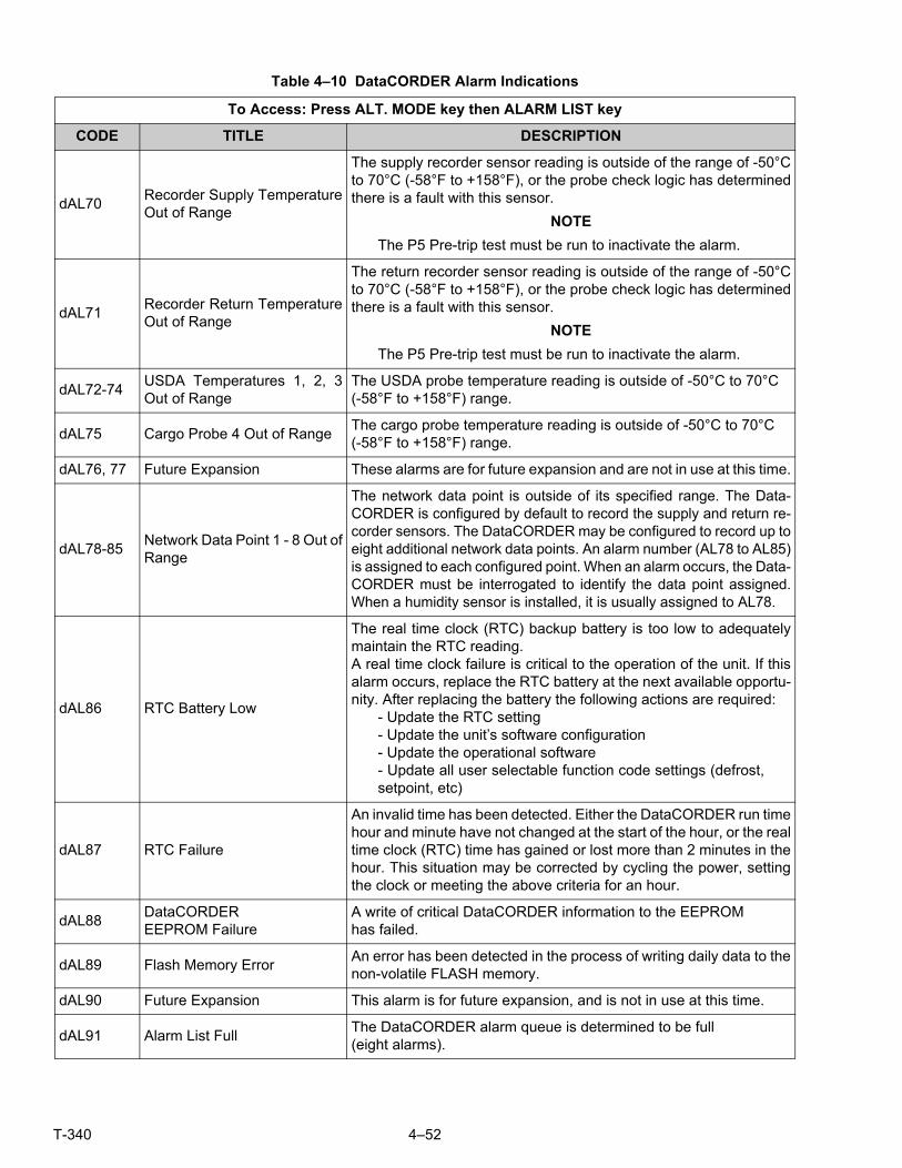
T-340 4–52
Table 4–10 DataCORDER Alarm Indications
To Access: Press ALT. MODE key then ALARM LIST key
CODE TITLE DESCRIPTION
dAL70Recorder Supply TemperatureOut of Range
The supply recorder sensor reading is outside of the range of -50°Cto 70°C (-58°F to +158°F), or the probe check logic has determinedthere is a fault with this sensor.
NOTE
The P5 Pre-trip test must be run to inactivate the alarm.
dAL71Recorder Return TemperatureOut of Range
The return recorder sensor reading is outside of the range of -50°Cto 70°C (-58°F to +158°F), or the probe check logic has determinedthere is a fault with this sensor.
NOTE
The P5 Pre-trip test must be run to inactivate the alarm.
dAL72-74USDA Temperatures 1, 2, 3Out of Range
The USDA probe temperature reading is outside of -50°C to 70°C (-58°F to +158°F) range.
dAL75 Cargo Probe 4 Out of RangeThe cargo probe temperature reading is outside of -50°C to 70°C (-58°F to +158°F) range.
dAL76, 77 Future Expansion These alarms are for future expansion and are not in use at this time.
dAL78-85Network Data Point 1 - 8 Out ofRange
The network data point is outside of its specified range. The Data-CORDER is configured by default to record the supply and return re-corder sensors. The DataCORDER may be configured to record up toeight additional network data points. An alarm number (AL78 to AL85)is assigned to each configured point. When an alarm occurs, the Data-CORDER must be interrogated to identify the data point assigned.When a humidity sensor is installed, it is usually assigned to AL78.
dAL86 RTC Battery Low
The real time clock (RTC) backup battery is too low to adequatelymaintain the RTC reading.A real time clock failure is critical to the operation of the unit. If thisalarm occurs, replace the RTC battery at the next available opportu-nity. After replacing the battery the following actions are required:
- Update the RTC setting- Update the unit’s software configuration- Update the operational software- Update all user selectable function code settings (defrost,setpoint, etc)
dAL87 RTC Failure
An invalid time has been detected. Either the DataCORDER run timehour and minute have not changed at the start of the hour, or the realtime clock (RTC) time has gained or lost more than 2 minutes in thehour. This situation may be corrected by cycling the power, settingthe clock or meeting the above criteria for an hour.
dAL88DataCORDER EEPROM Failure
A write of critical DataCORDER information to the EEPROM has failed.
dAL89 Flash Memory ErrorAn error has been detected in the process of writing daily data to thenon-volatile FLASH memory.
dAL90 Future Expansion This alarm is for future expansion, and is not in use at this time.
dAL91 Alarm List FullThe DataCORDER alarm queue is determined to be full (eight alarms).

5–1 T-340
SECTION 5
OPERATION
5.1 INSPECTION (BEFORE LOADING)
WARNING!Beware of unannounced starting of the evaporator and condenser fans. The unit may cycle thefans and compress or unexpectedly as control requirements dictate.
a. Check inside for the following:
1. Check channels or “T” bar floor for cleanliness. Channels must be free of debris for proper air circulation.
2. Check container panels, insulation and door seals for damage. Effect permanent or temporary repairs.
3. Visually check evaporator fan motor mounting bolts for proper securement (refer to Section 7.15).
4. Check for visible corrosion on the evaporator stator and fan deck (refer to Section 7.16).
5. Check for dirt or grease on evaporator fans or fan deck and clean if necessary.
6. Check evaporator coil for cleanliness or obstructions. Wash with fresh water.
7. Check defrost drain pans and drain lines for obstructions and clear if necessary. Wash with fresh water.
8. Check panels on refrigeration unit for loose bolts and condition of panels. Make sure T.I.R. devices are inplace on access panels.
b. Check condenser coil for cleanliness. Wash with fresh water.
c. Open control box door.Check for loose electrical connections or hardware.
d. Check color of moisture-liquid indicator.
5.2 CONNECT POWER
WARNING!Do not attempt to remove power plug(s) before turning OFF start-stop switch (ST), unit circuitbreaker(s) and external power source.
WARNING!Make sure the power plugs are clean and dry before connecting to power receptacle.
5.2.1 Connection To 380/460 VAC Power
1. Make sure start-stop switch (ST on control panel) and circuit breaker (CB-1 in the control box) are in position“0” (OFF).
2. Plug the 460 VAC (yellow) cable into a de-energized 380/460 VAC, 3-phase power source. Energize thepower source. Place circuit breaker (CB-1) in position “I” (ON). Close and secure control box door.
5.2.2 Connection To 190/230 VAC Power
An autotransformer (Figure 5.1) is required to allow operation on nominal 230 volt power. It is fitted with a 230 VACcable and a receptacle to accept the standard 460 VAC power plug. The 230 volt cable is black in color while the460 volt cable is yellow. The transformer may also be equipped with a circuit breaker (CB-2). The transformer is astep up transformer that will provide 380/460 VAC, 3-phase, 50/60 Hz power to the unit when the 230 VAC powercable is connected to a 190/230 VAC, 3-phase power source.
1. Make sure that the start-stop switch (ST, on control panel) and circuit breakers CB-1 (in the control box and CB-2 (on the transformer) are in position “0” (OFF). Plug in and lock the 460VACpower plug at the receptacle on thetransformer.
2. Plug the 230 VAC (black) cable into a de-energized 190/230 VAC, 3-phase power source. Energize thepower source. Set circuit breakers CB-1 and CB-2 to position “I” (ON). Close and secure control box door.
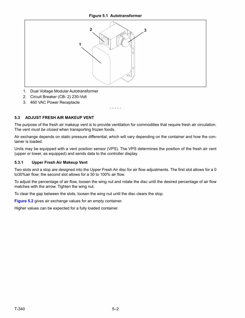
T-340 5–2
Figure 5.1 Autotransformer
1. Dual Voltage Modular Autotransformer
2. Circuit Breaker (CB- 2) 230-Volt
3. 460 VAC Power Receptacle
- - - - -
5.3 ADJUST FRESH AIR MAKEUP VENT
The purpose of the fresh air makeup vent is to provide ventilation for commodities that require fresh air circulation.The vent must be closed when transporting frozen foods.
Air exchange depends on static pressure differential, which will vary depending on the container and how the con-tainer is loaded.
Units may be equipped with a vent position sensor (VPS). The VPS determines the position of the fresh air vent(upper or lower, as equipped) and sends data to the controller display.
5.3.1 Upper Fresh Air Makeup Vent
Two slots and a stop are designed into the Upper Fresh Air disc for air flow adjustments. The first slot allows for a 0to30%air flow; the second slot allows for a 30 to 100% air flow.
To adjust the percentage of air flow, loosen the wing nut and rotate the disc until the desired percentage of air flowmatches with the arrow. Tighten the wing nut.
To clear the gap between the slots, loosen the wing nut until the disc clears the stop.
Figure 5.2 gives air exchange values for an empty container.
Higher values can be expected for a fully loaded container.
1
2 3

5–3 T-340
Figure 5.2 Upper Fresh Air Make Up Flow Chart
5.3.2 Lower Fresh Air Makeup Vent
a. Full Open or Closed Positions
Maximum air flow is achieved by loosening the wing nuts and moving the cover to the maximum open position(100% position). The closed position is 0% air flow position. The operator may also adjust the opening to increaseor decrease the air flow volume to meet the required air flow.
b. Reduced Flow for Lower Fresh Air Makeup
NOTEIn order to prevent inaccurate display readings on units equipped with a Vent Position Sensor (VPS),ensure that the rack and pinion drive of the VPS is not disrupted when adjusting the air makeup vent.
NOTEDo not loosen the hex nut beyond its stop. Doing so may cause inaccurate display readings and errorsin DataCORDER reports.
Similar to the Upper Fresh Air Makeup vent, two slots and a stop are designed into the Lower Fresh Air slide for airflow adjustments. The first slot allows for a 0 to 25% air flow; the second slot allows for a 25 to 100% air flow. Toadjust the percentage of air flow, loosen the hex nut and rotate the disc until the desired percentage of air flowmatches with the arrow. Tighten the hex nut. To clear the gap between the slots, loosen the hex nut until the discclears the stop.
0
50
100
150
200
250
0 10 20 30 40 50 60 70 80 90 100
TBAR 1 1/2”
TBAR2 5/8”TBAR 3”
AIR FLOW(CMH) 50HZ
PERCENT OPEN
0
50
100
150
200
250
300
0 10 20 30 40 50 60 70 80 90 100
TBAR 1 1/2”
TBAR2 5/8”TBAR 3”
AIR FLOW(CMH) 60HZ
PERCENT OPEN

T-340 5–4
On some models the air slide is supplied with two adjustable air control discs. The fresh air makeup can beadjusted for 15, 35, 50 or 75 cubic meters per hour (CMH). The air flow has been established at 60 Hz power and2-1/2 inch T bar and with 15 mm (0.6 inch) H2O external static above free blow.
Loosen the hex nut, adjust each disc to the required air flow, then tighten hex nut.
NOTEThe main air slide is in the fully closed position during reduced air flow operation when equipped withair control discs.
c. Air Sampling for Carbon Dioxide (CO2) Level
Loosen hex nuts and move the cover until the arrow on the cover is aligned with the “atmosphere samplingport” label. Tighten the hex nuts and attach a 3/8 in. hose to the sampling port.
If the internal atmosphere content has reached an unacceptable level, the operator may adjust the discopening to meet the required air flow volume to ventilate the container.
5.3.3 Vent Position Sensor
The VPS allows the user to determine the position of the fresh air vent via Cd45. This function code is accessiblevia the Code Select key.
The vent position will display for 30 seconds whenever motion corresponding to 5 CMH (3 CFM) or greater isdetected. It will scroll in intervals of 5 CMH (3 CFM). Scrolling toCd45 will display the Fresh Air Vent Position.
The position of the vent will be recorded in the DataCORDER whenever the unit is running under AC power andany of the following:
Trip start
On every power cycle
Midnight
Manual changes greater than 5 CMH (3 CFM) remaining in the new position for at least four minutes
NOTEThe user has four minutes to make necessary adjustments to the vent setting. This time calculationbegins on the initial movement of the sensor. The vent can be moved to any position within the fourminutes. On completion of the first four minutes, the vent is required to remain stable for the next fourminutes. If vent position changes are detected during the four-minute stability period, AL50 will begenerated. This provides the user with the ability to change the vent setting without generating multi-ple events in the DataCORDER.
5.4 EAUTOFRESH OPERATION
The eAutoFresh system allows the opening and closing of the mechanical air vent slide. The opening and closingof the slide is determined by the mode selected through Cd43.
The modes of operation are OFF, USER, TEST,DELAY, and GASLIMIT. Each mode of operation has submenuswith selectable parameters. Not all parameters are available in each submenu.
Upon power up, the controller will fully close the eAutoFresh air vent. Nine seconds after power up, the controllerwill check if there is a carbon dioxide (CO2) sensor connected.When a CO2 sensor is detected, the controller willenable access to the Gas Limit mode of operation. If no sensor is detected, the only modes of operation availablewill be Test, User, and Delay. The controller will then resume operation in the last mode of operation before powerinterruption.
5.4.1 eAutoFresh Pre-Trip Inspection
Pre-trip testing of the eAutoFresh system is performed during Pre-Trip test P0. Operation of the system may beobserved during this test.
Upon initiation of Pre-Trip P0, the current state will be saved and the vent will fully close. This will be followed bytwo sequences of opening to 100% and returning to the closed position. No other eAutoFresh mode of operationwill be available until the two cycles of opening and closing have completed. Upon termination of the test, the ventwill open to the previous state and operation will return to the previous mode.
If the last mode was gASLM, the vent will open to the preset FLO setting, the controller will start taking new read-ings and control based on those readings.

5–5 T-340
5.4.2 eAutoFresh Start-Up Procedure
To start the system, do the following:
a. Press the “CODE SELECT” key (see Figure 4.2).
b. Press the “UP or DOWN” arrow key until “Cd43” is displayed, then press “ENTER”.
c. Press the “UP or DOWN” arrow key to access the desired mode of operation.When the mode operation isdisplayed press the enter key to access the submenu parameters.
5.4.3 eAutoFresh Modes of Operation
NOTEWhen setting any mode of operation, complete the entire process to ensure all parameters are set.
a. OFF
A setting of OFF will disable all automatic venting operations. The eAutoFresh vent will be driven fully closed andthe eAutoFresh opening set to 0 CMH in Cd44. This is the default mode whenever a frozen mode of operation hasbeen selected. When the frozen set point is selected, the current eAutoFresh setting is saved. The vent positionwill be restored when a perishable set point is selected.
b. USER
The USER mode provides ventilation for commodities that require fresh air circulation. The flow rate can beaccessed through the submenu if a perishable set point has been selected. To set the flow rate, press the ENTERkey to activate the selection mode. When FLO appears in the left hand window, use the UP or DOWN arrow key toscroll to the desired opening. The range is from 0 to 220CM (0 to 129CF) in increments of 5. Press the ENTER keyto set the value and begin operation.
c. TEST
TEST mode allows the operator to test the movement of the mechanical slide air vent and calibrate the CO2 sen-sor.
tESt - When “tESt” appears in the left window, press the ENTER key to begin the test. The eAutoFresh slide willopen fully and then return to the closed position. The test may be observed by the operator to ensure proper opera-tion of the vent. After completion of the TEST, the unit will return to the previous mode of operation.
NOTEIt is recommended that the calibration procedure only be performed during Pre-trip or when the con-tainer has been fully vented.
CAL will attempt to calibrate the CO2 sensor. When “CAL” is selected the display will flash “CAL”. The operator isto hold the “ENTER” key for 5 seconds. The display will stop flashing and read “CAL” for 5 seconds. The micropro-cessor will read the CO2 value, and then compare that value to a known zero value. If the sensor is within the cali-bration parameter range, the microprocessor will determine the appropriate offset for the sensor. If the sensor isoutside of this range, for example if the container is loaded or has a high level of CO2, the controller will flash“NOCAL” for 5 seconds then revert to the previous mode of operation.
d. DELAY
In DELAY mode, the operation of the eAutoFresh system will be delayed for a set amount of time. This allows timefor the cargo to reach set point. In DELAY mode, the eAutoFresh vent will open to the stored (FLO) value when thereturn air temperature sensor (RTS) is at or below set point plus the return offset value (rtn) or the delay time (tIM),whichever comes first. The eAutoFresh vent will be fully closed when return air temperature is greater than the setpoint plus the offset temperature (rtn).
To set the unit in Delay mode, scroll until “DELAY” appears in the left window, press ENTER to activate the submenu.The first selection is the amount of time (tIM) for the delay. Select the amount of time for the delay by using the UPand DOWN arrow keys. The range is from 1 to 72 hours in 1 hour increments. Press the ENTER key to set the valueand move to the FLO rate. Use the UP or DOWN arrow key to scroll to the desired FLO rate. The range is from 0 to220CM (0 to 129CF) in increments of 5 and 3 respectively. Press the ENTER key to set the value and move to thereturn temperature offset. Use the UP or DOWN arrow key to scroll to the desired rtn rate. The range of offset is from0.6°C to 2.8°C (1.0° F to 2.8° F) in 0.1° increments. Press ENTER to set the value and begin operation.

T-340 5–6
e. GAS LIMIT (gASLM)
In GAS LIMIT mode, access to the submenu is available provided a perishable set point has been selected, and avalid reading is detected from the CO2 sensor. In “Gas limit” mode the microprocessor will monitor and limit thelevel of CO2 in the container by opening and closing the eAutoFresh vent. The vent will open to the (FLO) settingonce the unit has completed initial temperature pull down or if the cargo temperature is within 5°C of set point andthe CO2 level has reached the max limit or if the O2 level has reached the lower limit. After the first 15 minutes ofthe vent opening the controller will again evaluate the level of CO2, and/or O2 levels. If after the first 15 minutes thegas limit values are satisfied, the vent will close, if either gas limit has not been satisfied within 15 minutes the airexchange vent will open in 10 CMH increments every 15 minutes until both gas concentrations are satisfied. Onceall limits are satisfied the vent will return to the closed position. If conditions are not met with the slide open 100%for 90 minutes AL29 will be activated.
To operate in GAS LIMIT mode, scroll until gASLM appears in the left window, and press ENTER to activate thesubmenu. The first selection is the maximum CO2 level (CO2LM). Select the maximum CO2 level by using the UPand DOWN arrow keys. The range is from 0 to 19% in 1% increments. Press ENTER to set the value and move tothe minimum O2 level (O2LM). The range is from 2% to 20% in 1% increments. Press ENTER to set the value andmove to the FLO rate. Use the UP or DOWN arrow key to scroll to the desired FLO rate. The range is from 0 to220CM (0 to 129CF) in increments of 5 and 3 respectively. Press ENTER to set the value and begin operation.
Operational Parameters (Sub Menu Options):
FLO indicates the opening to which the slide will move based on the stored value in CMH (in increments of 5) orCFM depending on the selection of Cd46 (Airflow display units), Cd28 (Metric/Imperial) or the pressing of the degC/F key. CFM is displayed as CF, CMH is displayed as CM.
tIM is the time delay prior to the door opening. The time range is from 1 to 72 hrs in 1 hr increments.
CO2LM is the maximum level of CO2 that is allowed for the cargo. The range is from 0% to 19% in 1% increments,the default setting is 10.
O2LM is the minimum level of O2 that is allowed for the cargo. The range is from 2% to 20% in 1% increments, thedefault setting is 10.
Rtn is an offset value used to expand the return air temperature value to compensate for the fresh air entering thecontainer. The allowable range is from 0.6°C to 2.8°C or 1.0°F to 5.0°F in 0.1° increments the default setting is2.8°C (5°F).
5.5 CONNECT WATER-COOLED CONDENSER
The water-cooled condenser is used when cooling water is available and heating the surrounding air is objection-able, such as in a ship’s hold. If water-cooled operation is desired, connect in accordance with the following sub-paragraphs.
5.5.1 Water-Cooled Condenser with Water Pressure Switch
a. Connect the water supply line to the inlet side of condenser and the discharge line to the outlet side of thecondenser. (See Figure 3.5).
b. Maintain a flow rate of 11 to 26 liters per minute (3 to 7 gallons per minute). The water pressure switch willopen to de-energize the condenser fan relay. The condenser fan motor will stop and will remain stoppeduntil the water pressure switch closes.
c. To shift to air-cooled condenser operation, disconnect the water supply and the discharge line to the water-cooled condenser. The refrigeration unit will shift to air-cooled condenser operation when the water pressureswitch closes.
5.5.2 Water-Cooled Condenser with Condenser Fan Switch
a. Connect the water supply line to the inlet side of condenser and the discharge line to the outlet side of thecondenser. (See Figure 3.5.)
b. Maintain a flow rate of 11 to 26 lpm (3 to 7 gpm).
c. Set the condenser fan switch to position “O.” This will de-energize the condenser fan relay. The condenserfan motor will stop and remain stopped until the CFS switch is set to position “I.”

5–7 T-340
CAUTION!When condenser water flow is below 11 lpm (3 gpm) or when water-cooled operation is not inuse, the CFS switch MUST be set to position “1” or the unit will not operate properly.
d. To shift to air-cooled condenser operation, stop the unit, set the CFS switch to positioI” and restart the unit.Disconnect the water lines to the water-cooled condenser.
5.6 CONNECT REMOTE MONITORING RECEPTACLE
If remote monitoring is required, connect the remote monitor plug at the unit receptacle, see item 9, Figure 3.6.
When the remote monitor plug is connected to the remote monitoring receptacle, the following remote circuits areenergized:
5.7 STARTING AND STOPPING INSTRUCTIONS
WARNING!Make sure that the unit circuit breaker(s) (CB-1 & CB-2) and the START-STOP switch (ST) are inthe “O” (OFF) position before connecting to any electrical power source.
NOTEThe electronic phase detection system will check for proper compressor rotation within the first 30 sec-onds. If rotation is not correct, the compressor will be stopped and restarted in the opposite direction.If the compressor is producing unusually loud and continuous noise after the first 30 seconds of oper-ation, stop the unit and investigate.
5.7.1 Starting the Unit
a. With power properly applied, the fresh air vent set and (if required) the water-cooled condenser connected(refer to Section 5.2, Section 5.3 & Section 5.5), place the START-STOP switch to “I” (ON), see Figure 3.6.
b. The Controller Function Codes for the container ID (Cd40), software version (Cd18) and unit model number(Cd20) will be displayed in sequence.
c. Continue with Start Up Inspection, Section 5.8.
5.7.2 Stopping the Unit
To stop the unit, place the START-STOP switch in position “0” (OFF).
5.8 START-UP INSPECTION
5.8.1 Physical Inspection
Check rotation of condenser and evaporator fans.
5.8.2 Check Controller Function Codes
Check, and if required, reset controller Function Codes (Cd27 through Cd39) in accordance with desired operatingparameters. Refer to Table 4–5.
CIRCUIT FUNCTION
Sockets B to A Energizes remote cool light
Sockets C to A Energizes remote defrost light
Sockets D to A Energizes remote in-range light

T-340 5–8
5.8.3 Start Temperature Recorder
Partlow Recorders
a. Open recorder door and check battery of electronic recorder. Be sure key is returned to storage clip of mechani-cal recorder.
b. Lift stylus (pen) by pulling the marking tip outward until the stylus arm snaps into the retracted position.
c. Install new chart, making sure chart is under the four corner tabs. Lower the stylus until it has made contact withthe chart. Close and secure the recorder door.
DataCORDER
a. Check and, if required, set the DataCORDER Configuration in accordance with desired recording parameter.Refer to Section 4.8.3.
b. Enter a “Trip Start.” To enter a “Trip Start,” do the following:
1. Depress the ALT MODE key.When the left display shows, dC, depress the ENTER key.
2. Scroll to Code dC30.
3. Depress and hold the ENTER key for five seconds.
4. The “Trip Start” event will be entered in the DataCORDER.
5.8.4 Complete Inspection
Allow the unit to run for five minutes to stabilize conditions, and then perform a Pre-trip diagnosis in accordancewith Section 5.9.
5.9 PRE-TRIP DIAGNOSIS
CAUTION!Pre-trip inspection should not be performed with critical temperature cargoes in the container.
CAUTION!When Pre-trip key is pressed, economy, dehumidification and bulb mode will be deactivated. At thecompletion of Pre- trip activity, economy, dehumidification and bulb mode must be reactivated.
Pre-trip diagnosis provides automatic testing of the unit components using internal measurements and comparisonlogic. The program will provide a “PASS” or “FAIL” display to indicate test results.
The testing begins with access to a Pre-trip selection menu. The user may have the option of selecting one of twoautomatic tests.
These tests will automatically perform a series of individual Pre-trip tests. The user may also scroll down to selectany of the individual tests.
When only the short sequence is configured, it will appear as “AUtO” in the display. Otherwise “AUtO1” will indicatethe short sequence and “AUtO2” will indicate the long sequence. The test short sequence will run tests P0 throughP6. The long test sequence will run tests P0 through P10.
A detailed description of the Pre-trip test codes is listed in Table 4–7. If no selection is made, the Pre-trip menuselection process will terminate automatically. However, dehumidification and bulb mode must be reactivated man-ually if required.
Scrolling down to the “rSLts” code and pressing ENTER will allow the user to scroll through the results of the lastPre-trip testing run. If no Pre-testing has been run (or an individual test has not been run) since the unit was pow-ered up, “- - - -” will be displayed.
5–9 T-340
To start a Pre-trip test, do the following:
NOTEPrior to starting a Pre-trip test, verify that unit voltage (Cd07) is within tolerance and unit amperagedraw (Cd04, Cd05, Cd06) are within expected limits. Otherwise, tests may fail incorrectly.
All alarms must be rectified and cleared before starting tests.
Pre-trip may also be initiated via communications. The operation is the same as for the keypad initia-tion described below except that should a test fail, the Pre-trip mode will automatically terminate.When initiated via communications, a Pre-trip test may not be interrupted with an arrow key, but thePre- trip test can be terminated with the PRE-TRIP key.
a. Press the PRE-TRIP key to accesses the Pre- trip test selection menu.
b. TO RUN AN AUTOMATIC TEST: Scroll through the selections by pressing the UP ARROW or DOWN ARROWkeys to display AUTO, AUTO 1, AUTO 2 or AUTO 3 as desired, then press ENTER.
1. The unit will execute the series of tests without any need for direct user interface. These tests vary in length,depending on the component under test.
2. While tests are running, “P#-#” will appear on the left display; the #’s indicate the test number and sub-test.The right display will show a countdown time in minutes and seconds, indicating the amount of time remain-ing in the test.
CAUTION!When a failure occurs during automatic testing, the unit will suspend operation awaiting oper-ator intervention.
When an automatic test fails, it will be repeated once. A repeated test failure will cause “FAIL” to be shown on theright display, with the corresponding test number to the left.
The user may then press the DOWN ARROW to repeat the test, the UP ARROW to skip to the next test, or the PRE-TRIP key to terminate testing. The unit will wait indefinitely or until the user manually enters a command.
CAUTION!When Pre-trip test Auto2 runs to completion without being interrupted, the unit will terminatePre-trip and display “Auto 2” “end.” The unit will suspend operation until the user depressesthe ENTER key!
When an Auto 1 Pre-trip test runs to completion without a failure, the unit will exit Pre-trip mode and return to normalcontrol operation. However, dehumidification and bulb mode must be reactivated manually if required.
c. TO RUN AN INDIVIDUAL TEST: Scroll through the selections by pressing the UP ARROW or DOWN ARROWkeys to display an individual test code. Pressing ENTER when the desired test code is displayed.
1. Individually selected tests, other than the LED/Display test, will perform the operations necessary to verifythe operation of the component. At the conclusion, PASS or FAIL will be displayed. This message willremain displayed for up to three minutes, during which time a user may select another test. If the three min-ute time period expires, the unit will terminate pre-trip and return to control mode operation.
2. While the tests are being executed, the user may terminate the pre- trip diagnostics by pressing and holdingthe PRE-TRIP key. The unit will then resume normal operation. If the user decides to terminate a test butremain at the test selection menu, the user may press the UP ARROW key. When this is done, all test out-puts will be de-energized and the test selection menu will be displayed.
3. During Pre-trip testing, current limiting and pressure limiting are both active, except during P-7 (High Pres-sure Switch Testing) when pressure limiting is turned off.
d. Pre-Trip Test Results
At the end of the pre-trip test selection menu, the message “P,” “rSLts” (Pre- trip results) will be displayed. Pressingthe ENTER key will allow the user to see the results for all sub tests (i.e., 1-0, 1-1, etc).
The results will be displayed as “PASS” or “FAIL” for all the tests run to completion since power up. If a test has notbeen run since power up, “- - - - -” will be displayed.
Once all Pre-test activity is completed, dehumidification and bulb mode must be reactivated manually if required.

T-340 5–10
5.10 PROBE DIAGNOSTICS
A complete temperature probe check is performed during the P5 Pre-trip test. A probe check is also run at the endof a defrost cycle; the defrost light will remain on during this period. If supply probes are within limits and returnprobes are within limits, the unit will return to normal operation. During normal operation, the controller continu-ously monitors and compares adjacent temperature probe readings.
The probe check procedure consists of running the evaporator fans for up to eight minutes in order to compare thereadings from the adjacent temperature probes. If a significant difference in temperature readings is detectedbetween probes, a defrost cycle, followed by another probe check may be initiated. Any continued disagreementbetween probes will prompt the controller to invalidate the failed temperature probe, and the backup probe will beused for temperature control.
In Perishable Mode, both pairs of supply and return probes are monitored for probe disagreement. Probe disagreementis considered a difference of 0.5°C (0.9°F) or greater between the supply air sensors and/ or a difference of 2.0°C(3.6°F) between the return air sensors. Probe disagreement found in either pair can trigger a defrost probe check.
In Frozen Mode, only the controlling probes are considered. Disagreement of the controlling probes can trigger adefrost probe check, which will occur when the difference between the sensors is greater than 2.0°C (3.6°F). Nor-mally, the controlling probes are the return probes but if both return probes are invalidated, the supply probes areused for control purposes. Probe disagreement of the non- controlling probe pair will not trigger a defrost probecheck.
If after the defrost probe check the supply probes agree and return probes agree, all supply and return sensors areconsidered valid and the unit returns to normal control.
In the Case of Probe Disagreement:
If the supply probes disagree and the return probes agree, the controller will invalidate the worst supply probe. If theprobe check is run as part of Pre-trip P-5, an alarm will be triggered for the invalidated probe. If it is a run time defrostprobe check, the invalidated probe will be passed over and no alarm will be triggered. However, if the best supplyprobe is greater than 1.2°C (2.2°F) difference with respect to its return probes, the best supply probe is also invali-dated. If unit is in Perishable Mode, a probe alarm will be triggered for both supply probes.
If the supply probes agree and the return probes disagree, invalidate the worst return probe. If the probe check isbeing run as part of Pre-trip P-5, an alarm will be triggered for the invalidated probe. If it is a run time defrost probecheck, the invalidated probe will be passed over and no alarm will be necessary. If the best return probe is greaterthan 1.2°C (2.2°F) difference with respect to its supply probes, then the best return probe is also invalidated. If theunit is in perishable mode, a probe alarm will be triggered for both return probes.
5.11 EMERGENCY BYPASS OPERATION
Emergency Bypass operation is used to override the controller, in the case of a controller malfunction, to keep the unitcooling. When Emergency Bypass is installed and turned on, the unit will remain in a continuous state of full cool untilthe Emergency Bypass switch is turned off.
To place the unit in the Emergency Bypass Operation:
a. Locate the connection diagram and connectors for the emergency bypass (EB) sensors behind the top leftside of the compressor.
b. Disconnect the emergency bypass connector from the controller connector and attach it to the emergencybypass module connector. See Figure 5.3.
c. Locate the wire tire located at the EB switch in the control box.
d. Cut the wire tie, then place the EB switch in the On position.
e. Place the Mode Switch (MS) in the Full Cool position to enable the system for cooling.
f. Manually control container air temperature by cycling the Mode switch between Full Cool and evaporatorFans Only.
To operate the fans only, the MODE switch must be in the FANS ONLY position and the EMERGENCY BYPASSswitch must be in the Bypass position.
The EBS module uses the system’s safety devices (high pressure switch, motor internal protectors, and heat termi-nation thermostat) to protect the system while in Emergency Bypass Mode.

5–11 T-340
CAUTION!The unit will remain in the full cooling mode as long as the EB switch is in the On position andthe Mode Switch is in the Full Cool position. If the cargo can be damaged by low temperatures,the operator must monitor container temperature and manually cycle operation as required tomaintain temperature within required limits.
When the Emergency Bypass switch is in the Bypass position, the EBS will be enabled.With the Mode switch in FullCool mode, the following will occur simultaneously:
a. The EBS switch will enable EBS input.
b. The phase detection circuit will detect the phase rotation and close to provide power to the compressor con-tactor.
c. The condenser fan contact will close to energize the condenser contactor and provide power to the con-denser fan motor.
d. The evaporator fan contact will close to energize the high speed evaporator contactor and provide power tothe evaporator fan motor.
e. The EBS electronic module will operate the EEV to control superheat.
To return the unit to normal operation:
1. Locate the connectors behind the compressor.
2. Disconnect the Emergency Bypass connector from the EBS module connector and reconnect it to the con-troller connector. See Figure 5.3.
3. Inside the control box, place the EB switch in the Off position.
4. Re-install the wire tie at the switch mounting.
Figure 5.3 Diagram of Emergency Bypass Connections
EMERGENCY BYPASSCONNECTOR


6–1 T-340
SECTION 6
TROUBLESHOOTING
CONDITION POSSIBLE CAUSE REMEDY/REFERENCE
6.1 UNIT WILL NOT START OR STARTS THEN STOPS
No power to unit
External power source OFF Turn on
Start-Stop switch OFF or defective Check
Circuit breaker tripped or OFF Check
Autotransformer not connected Section 5.2.2
Loss of control power
Circuit breaker OFF or defective Check
Control transformer defective Replace
Fuse (F3A/F3B) blown Check
Start-Stop switch OFF or defective Check
Component(s) not operating
Evaporator fan motor internal protector open Section 7.15
Condenser fan motor internal protector open Section 7.11
Compressor internal protector open Section 7.8
High pressure switch open Section 6.7
Heat termination thermostat open Replace
Malfunction of current sensor Replace
Compressor hums, but doesnot start
Low line voltage Check
Single phasing Check
Shorted or grounded motor windings Section 7.8
Compressor seized Section 7.8
6.2 UNIT OPERATES LONG OR CONTINUOUSLY IN COOLING
ContainerHot load Normal
Defective box insulation or air leak Repair
Refrigeration system
Shortage of refrigerant Section 7.3
Evaporator coil covered with ice Section 6.6
Evaporator coil plugged with debris Section 7.16
Evaporator fan(s) rotating backwards Section 7.14/Section 7.15
Air bypass around evaporator coil Check
Controller set too low Reset
Compressor service valves or liquid line shutoff valvepartially closed
Open valves completely
Dirty condenser Section 7.10
Compressor worn Section 7.8
Current limit (function code Cd32) set to wrong value Section 4.4.3
Economizer solenoid valve malfunction Section 7.21
Digital unloader valve stuck open Replace
Electronic expansion valve Replace

T-340 6–2
6.3 UNIT RUNS BUT HAS INSUFFICIENT COOLING
Refrigeration system
Abnormal pressures Section 6.7
Abnormal temperatures Section 6.16
Abnormal currents Section 6.17
Controller malfunction Section 6.9
Evaporator fan or motor defective Section 7.15
Compressor service valves or liquid line shutoff valvepartially closed
Open valves completely
Frost on coil Section 6.10
Digital unloader valve stuck open Replace
Electronic expansion valve Replace
6.4 UNIT WILL NOT HEAT OR HAS INSUFFICIENT HEATING
No operation of any kind
Start-Stop switch OFF or defective Check
Circuit breaker OFF or defective Check
External power source OFF Turn ON
No control power
Circuit breaker or fuse defective Replace
Control Transformer defective Replace
Evaporator fan internal motor protector open Section 7.15
Heat relay defective Check
Heater termination thermostat open Section 7.14
Unit will not heat or has insufficient heat
Heater(s) defective Section 7.14
Heater contactor or coil defective Replace
Evaporator fan motor(s) defective or rotating back-wards
Section 7.14/Section 7.15
Evaporator fan motor contactor defective Replace
Controller malfunction Section 6.9
Defective wiring Replace
Loose terminal connections Tighten
Low line voltage Section 3.3
6.5 UNIT WILL NOT TERMINATE HEATING
Unit fails to stop heating
Controller improperly set Reset
Controller malfunction Section 6.9
Heater termination thermostat remains closed alongwith the heat relay
Section 7.14
6.6 UNIT WILL NOT DEFROST PROPERLY
Will not initiate defrost automatically
Defrost timer malfunction (Cd27) Table 4–5
Loose terminal connections Tighten
Defective wiring Replace
Defrost temperature sensor defective or heat termi-nation thermostat open
Replace
Heater contactor or coil defective Replace
CONDITION POSSIBLE CAUSE REMEDY/REFERENCE
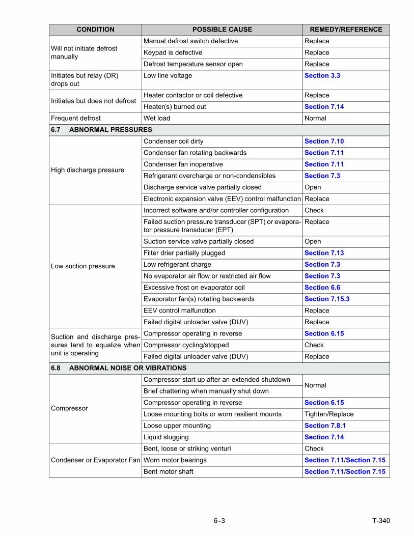
6–3 T-340
Will not initiate defrostmanually
Manual defrost switch defective Replace
Keypad is defective Replace
Defrost temperature sensor open Replace
Initiates but relay (DR) drops out
Low line voltage Section 3.3
Initiates but does not defrostHeater contactor or coil defective Replace
Heater(s) burned out Section 7.14
Frequent defrost Wet load Normal
6.7 ABNORMAL PRESSURES
High discharge pressure
Condenser coil dirty Section 7.10
Condenser fan rotating backwards Section 7.11
Condenser fan inoperative Section 7.11
Refrigerant overcharge or non-condensibles Section 7.3
Discharge service valve partially closed Open
Electronic expansion valve (EEV) control malfunction Replace
Low suction pressure
Incorrect software and/or controller configuration Check
Failed suction pressure transducer (SPT) or evapora-tor pressure transducer (EPT)
Replace
Suction service valve partially closed Open
Filter drier partially plugged Section 7.13
Low refrigerant charge Section 7.3
No evaporator air flow or restricted air flow Section 7.3
Excessive frost on evaporator coil Section 6.6
Evaporator fan(s) rotating backwards Section 7.15.3
EEV control malfunction Replace
Failed digital unloader valve (DUV) Replace
Suction and discharge pres-sures tend to equalize whenunit is operating
Compressor operating in reverse Section 6.15
Compressor cycling/stopped Check
Failed digital unloader valve (DUV) Replace
6.8 ABNORMAL NOISE OR VIBRATIONS
Compressor
Compressor start up after an extended shutdownNormal
Brief chattering when manually shut down
Compressor operating in reverse Section 6.15
Loose mounting bolts or worn resilient mounts Tighten/Replace
Loose upper mounting Section 7.8.1
Liquid slugging Section 7.14
Condenser or Evaporator Fan
Bent, loose or striking venturi Check
Worn motor bearings Section 7.11/Section 7.15
Bent motor shaft Section 7.11/Section 7.15
CONDITION POSSIBLE CAUSE REMEDY/REFERENCE

T-340 6–4
6.9 MICROPROCESSOR MALFUNCTION
Will not control
Incorrect software and/or controller configuration Check
Defective sensor Section 7.24
Defective wiring Check
Low refrigerant charge Section 7.3
6.10 NO EVAPORATOR AIR FLOW OR RESTRICTED AIR FLOW
Evaporator coil blockedFrost on coil Section 6.6
Dirty coil Section 7.14
No or partial evaporator air flow
Evaporator fan motor internal protector open Section 7.15
Evaporator fan motor(s) defective Section 7.15
Evaporator fan(s) loose or defective Section 7.15
Evaporator fan contactor defective Replace
6.11 EAUTOFRESH NOT OPERATING
Vent not opening
Unit not Configured for eAutoFresh Operation No action
Cd43 in Off mode Section 5.4.2
Wiring disconnected Check wiring
Stepper drive defective Section 7.26.2
Stepper motor defective Section 7.26.4
Unit operating in frozen mode Section 5.4.3
Gas Limit mode unavailable
Check CO2 sensor Section 5.4.3
Wiring disconnected Check wiring
Unit operating in frozen mode Section 5.4.3
Unable to calibrate CO2 sensor
“Enter” Key not held for sufficient length of time Section 5.4.3
CO2 outside of acceptable levels Check
Check CO2 sensor Section 5.4.3
Code 44 displays “- - - - - “Unit not Configured for eAutoFresh Operation No action
Check CO2 sensor Section 5.4.3
6.12 ELECTRONIC EXPANSION VALVE MALFUNCTION
Low suction pressure
Incorrect software and/or controller configuration Check
Failed suction pressure transducer (SPT) or evapora-tor pressure transducer (EPT)
Replace
Suction service valve partially closed Open
Filter drier partially plugged Section 7.13
Low refrigerant charge Section 7.3
No evaporator air flow or restricted air flow Section 7.14
Excessive frost on evaporator coil Section 6.6
Evaporator fan(s) rotating backwards Section 7.15.3
EEV control malfunction Section 7.17
Failed digital unloader valve (DUV) Replace
Loose or insufficiently clamped sensor Replace
CONDITION POSSIBLE CAUSE REMEDY/REFERENCE

6–5 T-340
High suction pressure with low superheat
Foreign material in valve Section 7.17
Failed suction pressure transducer (SPT) or evapora-tor pressure transducer (EPT)
Replace
EEV control malfunction Replace
Improperly seated powerhead Ensure powerhead is locked and in place
Liquid slugging in compressor
Failed suction pressure transducer (SPT) or evapora-tor pressure transducer (EPT)
Replace
Failed EEV Replace
6.13 AUTOTRANSFORMER MALFUNCTION
Unit will not start
Circuit breaker (CB-1 or CB-2) tripped Check
Autotransformer defective Section 7.22
Power source not turned ON Check
460 VAC power plug is not inserted into the receptacle Section 5.2.1
6.14 WATER−COOLED CONDENSER OR WATER PRESSURE SWITCH
High discharge pressureDirty coil
Section 7.12Non-condensibles
Condenser fan starts and stops
Water pressure switch malfunction Check
Water supply interruption Check
6.15 COMPRESSOR OPERATING IN REVERSE
NOTEThe compressor may start in reverse for up to 10 seconds to determine correct phase rotationif required for phase detection.
CAUTION!Allowing the scroll compressor to operate in reverse for more than two minutes will result ininternal compressor damage. Turn the start- stop switch OFF immediately.
Electrical
Incorrect wiring of compressor
CheckIncorrect wiring of compressor contactor(s)
Incorrect wiring of current sensor
CONDITION POSSIBLE CAUSE REMEDY/REFERENCE

T-340 6–6
6.16 ABNORMAL TEMPERATURES
High discharge temperature
Condenser coil dirty Section 7.10
Condenser fan rotating backwards Section 7.11
Condenser fan inoperative Section 7.11
Refrigerant overcharge or non-condensibles Section 7.3
Discharge service valve partially closed Open
Electronic expansion valve (EEV) control malfunction Replace
Failed suction pressure transducer (SPT) or evapora-tor pressure transducer (EPT)
Replace
Discharge temperature sensor drifting high Replace
Failed economizer expansion valve, economizer coil,or economizer solenoid valve
Replace
Plugged economizer expansion valve, economizercoil, or economizer solenoid valve
Replace
Loose or insufficiently clamped sensor Replace
6.17 ABNORMAL CURRENTS
Unit reads abnormal currents Current sensor wiring Check
CONDITION POSSIBLE CAUSE REMEDY/REFERENCE
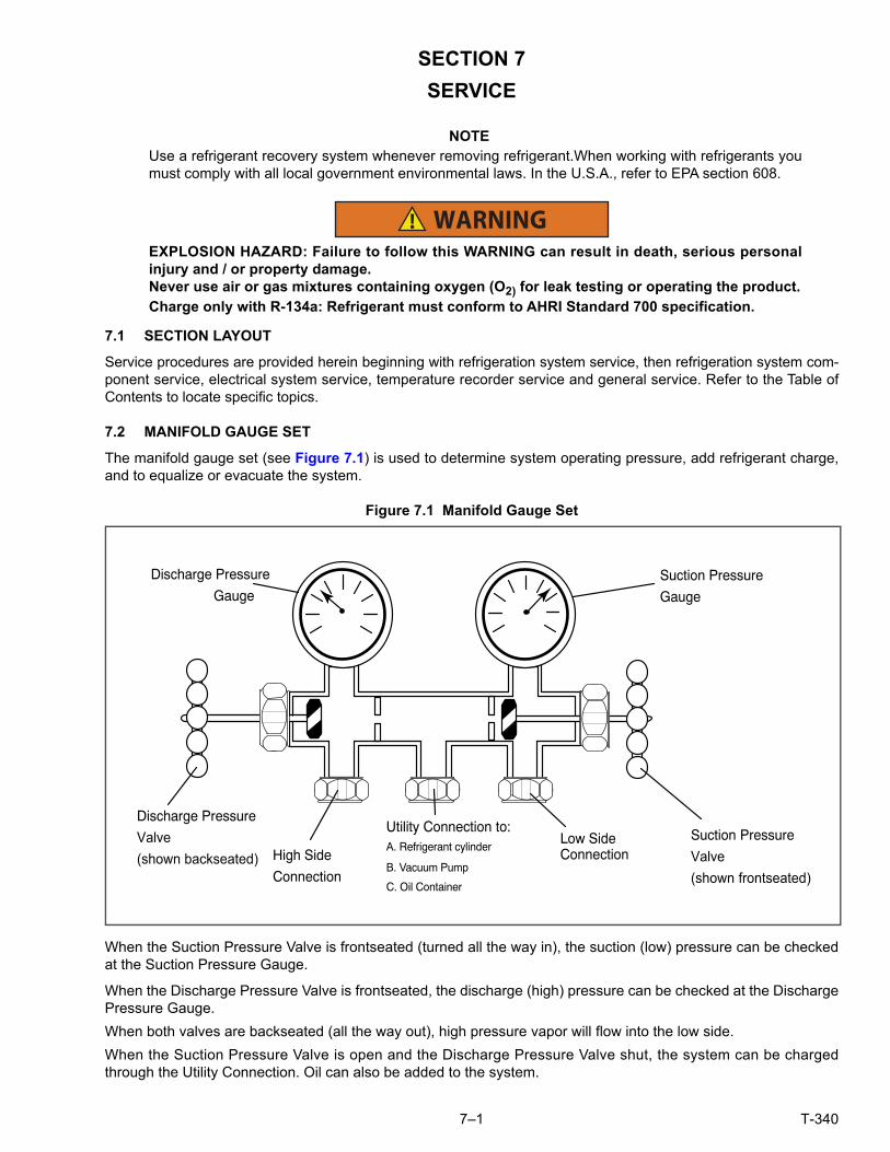
7–1 T-340
SECTION 7
SERVICE
NOTEUse a refrigerant recovery system whenever removing refrigerant.When working with refrigerants youmust comply with all local government environmental laws. In the U.S.A., refer to EPA section 608.
WARNING!EXPLOSION HAZARD: Failure to follow this WARNING can result in death, serious personalinjury and / or property damage.Never use air or gas mixtures containing oxygen (O2) for leak testing or operating the product.Charge only with R-134a: Refrigerant must conform to AHRI Standard 700 specification.
7.1 SECTION LAYOUT
Service procedures are provided herein beginning with refrigeration system service, then refrigeration system com-ponent service, electrical system service, temperature recorder service and general service. Refer to the Table ofContents to locate specific topics.
7.2 MANIFOLD GAUGE SET
The manifold gauge set (see Figure 7.1) is used to determine system operating pressure, add refrigerant charge,and to equalize or evacuate the system.
Figure 7.1 Manifold Gauge Set
When the Suction Pressure Valve is frontseated (turned all the way in), the suction (low) pressure can be checkedat the Suction Pressure Gauge.
When the Discharge Pressure Valve is frontseated, the discharge (high) pressure can be checked at the DischargePressure Gauge.
When both valves are backseated (all the way out), high pressure vapor will flow into the low side.
When the Suction Pressure Valve is open and the Discharge Pressure Valve shut, the system can be chargedthrough the Utility Connection. Oil can also be added to the system.
Utility Connection to:A. Refrigerant cylinder
B. Vacuum Pump
C. Oil Container
Discharge Pressure
GaugeSuction Pressure
Gauge
Suction Pressure
Valve(shown frontseated)
Low SideConnectionHigh Side
Connection
Discharge Pressure
Valve(shown backseated)

T-340 7–2
A R-134a manifold gauge/hose set with self-sealing hoses (see Figure 7.2) is required for service of the modelscovered within this manual. The manifold gauge/hose set is available from Carrier Transicold. (Carrier Transicoldpart number 07-00294-00, which includes items 1 through 6, Figure 7.2.)
If the manifold gauge/hose set is new or was exposed to the atmosphere, it will need to be evacuated to removecontaminants and air as follows:
1. Backseat (turn counterclockwise) both field service couplings (see Figure 7.2) and midseat both handvalves.
2. Connect the yellow hose to a vacuum pump and refrigerant 134a cylinder.
Figure 7.2 R-134a Manifold Gauge/Hose Set
1. RED Refrigeration and/or Evacuation Hose (SAE J2196/R-134a)
2. Hose Fitting (0.5-16 Acme)
3. YELLOW Refrigeration and/or Evacuation Hose (SAE J2196/R-134a)
4. Hose Fitting with O-ring (M14 x 1.5)
5. High Side Field Service Coupling (Red Knob)
6. BLUE Refrigeration and/or Evacuation Hose (SAE J2196/R-134a)
7. Low Side Field Service Coupling (Blue Knob)
- - - - -
3. Evacuate to 10 inches of vacuum and then charge with R-134a to a slightly positive pressure of 0.1 kg/ cm2
(1.0 psig).
4. Frontseat both manifold gauge set valves and disconnect from cylinder. The gauge set is now ready for use.
7.3 SERVICE CONNECTIONS
The compressor suction, compressor discharge, and the liquid line service valves (see Figure 7.3) are provided witha double seat and an access valve which enables servicing of the compressor and refrigerant lines.
Turning the valve stem clockwise (all the way forward) will frontseat the valve to close off the line connection andopen a path to the access valve. Turning the stem counterclockwise (all the way out) will backseat the valve toopen the line connection and close off the path to the access valve.
With the valve stem midway between frontseat and backseat, both of the service valve connections are open to theaccess valve path.
For example, the valve stem is first fully backseated when connecting a manifold gauge to measure pressure.Then, the valve is opened 1/4 to 1/2 turn to measure the pressure.
To High SideAccess Valve
To Low SideAccess Valve
1
2
2
3
4 54
6
7

7–3 T-340
Figure 7.3 Service Valve
1. Line Connection2. Access Valve3. Stem Cap4. Valve stem
5. Compressor Or Filter Drier Inlet Connection6. Valve (Frontseated)7. Valve (Backseated)
- - - - -
Connection of the manifold gauge/hose set (see Figure 7.4) is dependent on the component being serviced. If onlythe compressor is being serviced, the high side coupling is connected to the discharge service valve.
For service of the low side (after pump down), the high side coupling is connected to the liquid line service valve.The center hose connection is brought to the tool being used (vacuum, tank, etc.).
Connecting the manifold gauge set:
a. Remove service valve stem cap and to make sure the valve is backseated.
b. Remove access valve cap (See Figure 7.3).
c. Connect the field service coupling (see Figure 7.2) to the access valve.
d. Turn the field service coupling knob clockwise, which will open the system to the gauge set.
e. To read system pressures, slightly midseat the service valve.
f. Repeat the procedure to connect the other side of the gauge set.
CAUTION!To prevent trapping liquid refrigerant in the manifold gauge set be sure set is brought to suc-tion pressure before disconnecting.
Removing the Manifold Gauge Set:
a. While the compressor is still ON, backseat the high side service valve.
b. Midseat both hand valves on the manifold gauge set and allow the pressure in the manifold gauge set to bedrawn down to low side pressure. This returns any liquid that may be in the high side hose to the system.
c. Backseat the low side service valve. Backseat both field service couplings and frontseat both manifold handvalves. Remove couplings from access valves.
d. Install both service valve stem caps and service port caps (finger-tight only).
7.4 PUMP DOWN THE UNIT
To service the filter drier, economizer, expansion valves, economizer solenoid valve, digital unloader valve or evap-orator coil, pump the refrigerant into the high side as follows:
CAUTION!The scroll compressor achieves low suction pressure very quickly. Do not use the compressorto evacuate the system below 0 psig. Never operate the compressor with the suction or dis-charge service valves closed (frontseated). Internal damage will result from operating the com-pressor in a deep vacuum.
1
23
4
56 7

T-340 7–4
a. Attach manifold gauge set to the compressor suction and discharge service valves. Refer to Section 7.2.
b. Start the unit and run in the frozen mode (controller set below -10°C (14°F) for 10 to 15 minutes.
c. Check function code Cd21 (refer to Section 4.2.2). The economizer solenoid valve should be open. If not,continue to run until the valve opens.
d. Frontseat the liquid line service valve. Place Start-Stop switch in the OFF position when the suction reaches apositive pressure of 0.1 bar (1.4 psig).
e. Frontseat the suction and discharge service valves. The refrigerant will be trapped between the compressordischarge service valves and the liquid line valve.
f. Before opening up any part of the system, a slight positive pressure should be indicated on the pressuregauge. Remove power from the unit before opening any part of the system. If a vacuum is indicated, emitrefrigerant by cracking the liquid line valve momentarily to build up a slight positive pressure.
g. When opening up the refrigerant system, certain parts may frost. Allow the part to warm to ambient tempera-ture before dismantling. This avoids internal condensation which puts moisture in the system.
h. After repairs have been made, be sure to perform a refrigerant leak check (refer to Section 7.5), and evac-uate and dehydrate the low side (refer to Section 7.6.1).
i. Check refrigerant charge (refer to Section 7.7.1).
7.5 REFRIGERANT LEAK CHECKING
WARNING!EXPLOSION HAZARD Failure to follow this WARNING can result in death, serious personalinjury and / or property damage.Never use air or gas mixtures containing oxygen (O2) for leak testing or operating the product.Charge only with R-134a: Refrigerant must conform to AHRI Standard 700 specification.
a. The recommended procedure for finding leaks in a system is with a R-134a electronic leak detector. Testingjoints with soapsuds is satisfactory only for locating large leaks.
b. If the system is without refrigerant, charge the system with refrigerant 134a to build up pressure between2.1to 3.5 bar (30.5 to 50.8 psig). To ensure complete pressurization of the system, refrigerant should becharged at the compressor suction valve and the liquid line service valve. Remove refrigerant cylinder andleak-check all connections.
NOTEOnly refrigerant 134a should be used to pressurize the system. Any other gas or vapor will contami-nate the system, which will require additional purging and evacuation of the system.
c. If required, remove refrigerant using a refrigerant recovery system and repair any leaks. Check for leaks.
d. Evacuate and dehydrate the unit. (Refer to Section 7.6.1.)
e. Charge unit per Section 7.7.1.
7.6 EVACUATION AND DEHYDRATION
7.6.1 General
Moisture is detrimental to refrigeration systems. The presence of moisture in a refrigeration system can have manyundesirable effects. The most common are copper plating, acid sludge formation, “freezing-up” of metering devicesby free water, and formation of acids, resulting in metal corrosion.
7.6.2 Preparation
a. Evacuate and dehydrate only after pressure leak test (refer to Section 7.5).
b. Essential tools to properly evacuate and dehydrate any system include a vacuum pump (8m3/hr = 5 cfm vol-ume displacement) and an electronic vacuum gauge. The pump is available from Carrier Transicold, P/N07-00176-11. The micron gauge is P/N 07- 00414- 00.

7–5 T-340
c. If possible, keep the ambient temperature above 15.6°C (60°F) to speed evaporation of moisture. If the ambienttemperature is lower than 15.6°C (60°F), ice might form before moisture removal is complete. Heat lamps oralternate sources of heat may be used to raise the system temperature.
d. Additional time may be saved during a complete system pump down by replacing the filter drier with a sec-tion of copper tubing and the appropriate fittings. Installation of a new drier may be performed during thecharging procedure.
Figure 7.4 Refrigeration System Service Connections
1. Liquid Service Connection2. Receiver or Water Cooled Condenser3. Compressor4. Discharge Service Connection5. Suction Service Connection
6. Vacuum Pump7. Electronic Vacuum Gauge8. Manifold Gauge Set9. Refrigerant Cylinder10. Reclaimer
- - - - -
7.6.3 Complete System
NOTERefer to Partial System procedure for information pertaining to partial system evacuation and dehydration.
a. Remove all refrigerant using a refrigerant recovery system.
b. The recommended method to evacuate and dehydrate the system is to connect evacuation hoses at thecompressor suction and liquid line service valve (see Figure 7.4). Be sure the service hoses are suited forevacuation purposes.
c. Test the evacuation setup for leaks by backseating the unit service valves and drawing a deep vacuum withthe vacuum pump and gauge valves open. Shut off the pump and check to see if the vacuum holds. Repairleaks if necessary.
d. Midseat the refrigerant system service valves.
e. Open the vacuum pump and electronic vacuum gauge valves, if they are not already open. Start the vacuumpump. Evacuate unit until the electronic vacuum gauge indicates 2000 microns. Close the electronic vac-uum gauge and vacuum pump valves. Shut off the vacuum pump. Wait a few minutes to be sure the vac-uum holds.
f. Break the vacuum with either clean dry refrigerant 134a or dry nitrogen. Raise system pressure to roughly0.14 bar (2 psig), monitoring it with the compound gauge.
g. Remove refrigerant using a refrigerant recovery system.
h. Repeat steps e. and f. one time.
DS
1
2 34
5
6
7
8
9
10

T-340 7–6
i. Remove the copper tubing and change the filter drier. Evacuate unit to 500 microns. Close the electronicvacuum gauge and vacuum pump valves. Shut off the vacuum pump. Wait five minutes to see if vacuumholds. This procedure checks for residual moisture and/or leaks.
j. With a vacuum still in the unit, the refrigerant charge may be drawn into the system from a refrigerant con-tainer on weight scales.
7.6.4 Partial System
a. If refrigerant charge has been removed from the low side only, evacuate the low side by connecting theevacuation set-up at the compressor suction valve and the liquid service valve but leave the service valvesfrontseated until evacuation is completed.
b. Once evacuation has been completed and the pump has been isolated, fully backseat the service valves toisolate the service connections and then continue with checking and, if required, adding refrigerant in accor-dance with normal procedures.
7.7 REFRIGERANT CHARGE
WARNING!EXPLOSION HAZARD Failure to follow this WARNING can result in death, serious personalinjury and / or property damage.Never use air or gases containing oxygen (O2) for leak testing or operating the product.Charge only with R- 134a: Refrigerant must conform to AHRI Standard 700 specification.
7.7.1 Checking the Refrigerant Charge
NOTEUse a refrigerant recovery system whenever removing refrigerant.When working with refrigerants youmust comply with all local government environmental laws. In the U.S.A., refer to EPA Section 608.
a. Connect the gauge manifold to the compressor discharge and suction service valves. For units operating ona water cooled condenser, change over to air cooled operation.
b. Bring the container temperature to approximately 0°C (32°F) or below. Then set the controller set point to -25°C (-13°F).
c. Partially block the condenser coil inlet air. Increase the area blocked until the compressor discharge pres-sure is raised to approximately 12.8 bar (185 psig).
d. On units equipped with a receiver, the level should be between the glasses. On units equipped with a water-cooled condenser, the level should be at the center of the glass. If the refrigerant level is not correct, con-tinue with the following paragraphs to add or remove refrigerant as required.
7.7.2 Adding Refrigerant to System (Full Charge)
a. Evacuate unit and leave in deep vacuum. (Refer to Section 7.6.1.)
b. Place cylinder of R-134a on scale and connect charging line from cylinder to liquid line valve. Purgecharging line at liquid line valve and then note weight of cylinder and refrigerant.
c. Open liquid valve on cylinder. Open liquid line valve half-way and allow liquid refrigerant to flow into the unituntil the correct weight of refrigerant (refer to Section 3.2) has been added as indicated by scales.
NOTEIt may be necessary to finish charging unit through suction service valve in gas form, due to pressurerise in high side of the system.
d. Backseat manual liquid line valve (to close off gauge port). Close liquid valve on cylinder.
e. Start unit in cooling mode. Run for approximately 10 minutes and check the refrigerant charge.
7.7.3 Adding Refrigerant to System (Partial Charge)
a. Examine refrigerant system for any evidence of leaks, repair as necessary. (Refer to Section 7.5).
b. Maintain the conditions outlined in Section 7.7.1.

7–7 T-340
c. Fully backseat the suction service valve and remove the service port cap.
d. Connect charging line between suction service valve port and cylinder of refrigerant R-134a. Open VAPORvalve.
e. Partially frontseat (turn clockwise) the suction service valve and slowly add charge until the refrigerantappears at the proper level. Be careful not to frontseat the suction valve fully, if the compressor is operatedin a vacuum, internal damage may result.
7.8 COMPRESSOR
WARNING!Make sure power to the unit is OFF and power plug disconnected before replacing the compressor.
WARNING!Before disassembly of the compressor, be sure to relieve the internal pressure very carefullyby slightly loosening the couplings to break the seal.
CAUTION!The scroll compressor achieves low suction pressure very quickly. Do not use the compressorto evacuate the system below 0 psig. Never operate the compressor with the suction or dis-charge service valves closed (frontseated). Internal damage will result from operating the com-pressor in a deep vacuum.
7.8.1 Removal and Replacement of Compressor
a. Turn the unit ON and run it in full cool mode for 10 minutes.
NOTEIf the compressor is not operational, front-seat the suction and discharge service valves and go to stepe. below.
b. Frontseat the manual liquid line valve and allow the unit to pull-down to 0.1 kg/cm2 (1 psig).
c. Turn the unit start-stop switch (ST) and unit circuit breaker (CB-1) OFF, and disconnect power to the unit.
d. Frontseat the discharge and suction service valves.
e. Remove all remaining refrigerant from the compressor using a refrigerant recovery system.
f. Remove the compressor terminal cover, disconnect the ground wire and pull the cable plug from the com-pressor terminals. Install the terminal cover back after removing the power cable.
NOTEInspect the power cable (plug) terminals to ensure they are not deformed or have any signs of heat orarcing. If any damage is noted, replace the power cable.
g. Remove the Rotalock fittings from the suction and discharge service connections, and uncouple the unloader andeconomizer lines from the compressor.
h. Cut the dome temperature sensor (CPDS) wires. The replacement compressor comes with a CPDS alreadyassembled.
i. Remove and save the compressor base mounting bolts. Discard the 4 top resilient mounts and washers.
j. Remove (slide out) the old compressor from the unit.
k. Inspect compressor base plate for wear. Replace, if necessary.
l. Wire tie the compressor base plate to the compressor, and slide the new compressor into the unit. (Refer toFigure 7.5).

T-340 7–8
Figure 7.5 Compressor Kit
1. Compressor2. Teflon Seal for Valve Connection (2)3. O-Ring (Unloader Connection)4. Compressor Discharge Temperature Sensor5. O-Ring (Economizer Connection)6. Base Mounting Bolts7. SST Washers
8. Resilient Mount9. Mylar Washers10. Wire Ties11. Power Cable Gasket12. Ground Connection Screw13. Power Cable Lubricant - Krytox (Not Shown)
- - - - -
NOTEDO NOT add any oil to the replacement compressor. Replacement compressor is shipped with full oilcharge of 60 oz.
m. Cut and discard the wire ties used to hold the base plate to the compressor.
n. Place the new SST washers on each side of the resilient mounts, and the new Mylar washer on the bottomof it as shown in Figure 7.5. Install the four base mounting bolts loosely.
o. Place the new Teflon seals at the compressor suction and discharge ports as well as the O-rings at theunloader and economizer line connection ports. Hand tighten all four connections.
p. Torque the four base-mounting screws to 6.2 mkg (45 ft- lbs).
q. Torque the compressor ports / connections to:
r. Connect (butt-splice and heat shrink) the new compressor dome temperature sensor with the old sensorwires removed in step h. Wire-tie any loose wiring as appropriate.
s. Evacuate the compressor to 1000microns if the unit was pumped down before the replaced compressor wasremoved. Otherwise, evacuate the complete unit and charge it with R-134a refrigerant (see Section 7.6.1and Section 7.7.1).
t. Open the compressor terminal cover and connect the compressor power cable following the steps below:
1. Liberally coat the orange gasket surfaces with the Krytox lubricant.
1
2
3
5
2
7
4
6
8
9 7
10
11 12
Service Valve / Connection Torque Value
Suction and Discharge Rotalocks 108.5 to 135.5 Nm (80 to 100 ft-lbs.)
Unloader connection 24.5 to 27 Nm (18 to 20 ft-lbs.)
Economized connection 32.5 to 35 Nm (24 to 26 ft-lbs.)

7–9 T-340
2. Install the orange gasket part onto the compressor fusite with the grooved or threaded side out. Ensurethat the gasket is seated onto the fusite base.
3. Coat the inside of the power plug (female) connector pins with the Krytox lubricant, and insert the plugonto the compressor terminal connections. Make sure the orange gasket has bottomed out onto thefusite and it fits securely onto the terminal pins while fully inserted into the orange plug.
4. Connect the green ground wire to the grounding tab located inside the terminal box of the compressorusing the self-tapping grounding screw. Close the compressor terminal box using the terminal coverremoved in step t.
u. Backseat all service valves, connect the power to the unit and run it for at least 20 minutes.
v. Perform a leak check of the system.
7.9 HIGH PRESSURE SWITCH
7.9.1 Checking High Pressure Switch
WARNING!Do not use a nitrogen cylinder without a pressure regulator.
NOTEThe high pressure switch is non-adjustable.
a. Remove switch as outlined in Section 7.9.2.
b. Connect ohmmeter or continuity light across switch terminals. Ohmmeter will indicate no resistance or continuitylight will be illuminated if the switch closed after relieving compressor pressure.
c. Connect hose to a cylinder of dry nitrogen. (See Figure 7.6.)
Figure 7.6 High Pressure Switch Testing
1. Cylinder Valve and Gauge2. Pressure Regulator3. Nitrogen Cylinder
4. Pressure Gauge (0 to 36 kg/cm2 = 0 to 400 psig)5. Bleed-Off Valve6. 1/4 inch Connection
- - - - -
d. Set nitrogen pressure regulator at 26.4 kg/cm2 (375 psig) with bleed-off valve closed.
e. Close valve on cylinder and open bleed-off valve.
f. Open cylinder valve. Slowly close bleed-off valve to increase pressure on switch. The switch should open ata static pressure up to 25 kg/cm2 (350 psig). If a light is used, the light will go out. If an ohmmeter is used,the meter will indicate open circuit.
g. Slowly open bleed-off valve to decrease the pressure. The switch should close at 18 kg/cm2 (250 psig).
7.9.2 Replacing High Pressure Switch
a. Remove the refrigerant charge.
b. Disconnect wiring from defective switch. The high pressure switch is located on the discharge connection orline and is removed by turning counterclockwise.
1
2
3
4
5
6

T-340 7–10
c. Install a new high pressure switch after verifying switch settings.
d. Evacuate, dehydrate and recharge the system.
e. Start the unit, verify refrigeration charge and oil level.
7.10 CONDENSER COIL
The condenser coil consists of a series of parallel copper tubes expanded into copper fins. The condenser coil must becleaned with fresh water or steam so the air flow is not restricted. To replace the coil, do the following:
WARNING!Do not open the condenser fan grille before turning power OFF and disconnecting the power plug.
a. Using a refrigerant reclaim system, remove the refrigerant charge.
b. Remove the condenser coil guard.
c. Unsolder the lines and remove the line to the receiver or water-cooled condenser.
d. Remove the coil mounting hardware and remove the coil from the unit.
e. Install the replacement coil and solder connections.
f. Leak-check the coil connections per Section 7.5.
g. Evacuate the unit then charge the unit with refrigerant.
7.11 CONDENSER FAN AND MOTOR ASSEMBLY
WARNING!Do not open the condenser fan grille before turning power OFF and disconnecting the power plug.
The condenser fan rotates counter-clockwise (viewed from front of unit), pulls air through the condenser coil, anddischarges horizontally through the front of the unit.
To replace the condenser fan motor assembly:
a. Open condenser fan screen guard.
b. Loosen two square head set screws on fan. (Thread sealer has been applied to set screws at installation.)
c. Disconnect wiring connector.
CAUTION!Take necessary steps (place plywood over coil or use sling on motor) to prevent motor fromfalling into condenser coil.
d. Remove motor mounting hardware and replace the motor. It is recommended that new locknuts be usedwhen replacing motor.
e. Connect the wiring connector.
f. Install fan loosely on motor shaft (hub side in). DO NOT USE FORCE. If necessary, tap the hub only, not thehub nuts or bolts. Install venturi. Apply “Loctite H” to fan set screws. Adjust fan within venturi so that theouter edge of the fan is within 2.0 +/- 0.07 mm (0.08” +/- 0.03”) from the outside of the orifice opening. Spinfan by hand to check clearance.
g. Close and secure condenser fan screen guard.
7.12 WATER-COOLED CONDENSER CLEANING
The water-cooled condenser is of the shell and coil type with water circulating through the cupro-nickel coil. Therefrigerant vapor is admitted to the shell side and is condensed on the outer surface of the coil.
Rust, scale and slime on the water-cooling surfaces inside of the coil interfere with the transfer of heat, reduce sys-tem capacity, cause higher head pressures and increase the load on the system.

7–11 T-340
By checking the leaving water temperature and the actual condensing temperature, it can be determined if the con-denser coil is becoming dirty. A larger than normal difference between leaving condensing water temperature andactual condensing temperature, coupled with a small difference in temperature of entering and leaving condensingwater, is an indication of a dirty condensing coil.
To find the approximate condensing temperature, with the unit running in the cooling mode, install a gauge 0 to36.2 kg/cm2 (0 to 500 psig) on the compressor discharge service valve.
Example: Discharge pressure is 10.3 kg/cm2 (146.4 psig). Referring to Table 7–5 (R-134a pressure/ temperaturechart), the 10.3 kg/cm2 (146.4 psig) value converts to 43°C (110°F).
If the water-cooled condenser is dirty, it may be cleaned and de-scaled by the following procedure:
a. Turn unit off and disconnect main power.
b. Disconnect water pressure switch tubing by loosening the two flare nuts. Install one-quarter inch flare capon water-cooled condenser inlet tube (replaces tubing flare nut). De-scale tubing if necessary.
What You Will Need:
1. Oakite Aluminum Cleaner® 164, available as a powder in 20 kg (44 lb) pails and 205 kg (450 lb) drums.
2. Oakite Composition No. 32, available as a liquid in cases, each containing 3.785 liters (4 U.S. gallon) bottlesand also in carboys of 52.6 kg (116 lbs) net.
3. Fresh clean water.
4. Acid proof pump and containers or bottles with rubber hose.
NOTEWhen Oakite Compound No. 32 is used for the first time, the local Oakite Technical Service representa-tive should be called in for suggestions in planning the procedure. The representative will advise thereader on how to do the work with a minimum dismantling of equipment: how to estimate the time andamount of compound required; how to prepare the solution; how to control and conclude the de-scalingoperation by rinsing and neutralizing equipment before putting it back into service. The representative’sknowledge of metals, types of scale, water conditions and de-scaling techniques will be highly useful.
Summary of Procedure:
1. Drain water from condenser tubing circuit.
2. Clean water tubes with Oakite Aluminum Cleaner) 164 to remove mud and slime.
3. Flush.
4. De-scale water tubes with Oakite No. 32 to remove scale.
5. Flush.
6. Neutralize.
7. Flush.
8. Put unit back in service under normal load and check head (discharge) pressure.
Detailed Procedure:
1. Drain and flush the water circuit of the condenser coil. If scale on the tube inner surfaces is accompanied byslime, a thorough cleaning is necessary before de-scaling process can be accomplished.
2. To remove slime or mud, use Aluminum Cleaner® 164. Mixed 170 grams (6 ounces) per 3.785 liters (1 U.S.gallon) of water. Mix cleaner in one half the volume of water, while stirring, and then add remaining water.Warm this solution and circulate through the tubes until all slime and mud has been removed.
3. After cleaning, flush tubes thoroughly with fresh clean water.
4. Prepare a 15% by volume solution for de-scaling, by diluting Oakite Compound No. 32 with water. This isaccomplished by slowly adding 0.47 liter (1 U.S. pint) of the acid (Oakite No. 32) to 2.8 liters (3 U.S. quarts)of water.

T-340 7–12
WARNING!Oakite No. 32 is an acid. Be sure that the acid is slowly added to the water. DO NOT PUTWATER INTO THE ACID - this will cause spattering and excessive heat.
WARNING!Wear rubber gloves and wash the solution from the skin immediately if accidental contactoccurs. Do not allow the solution to splash onto concrete.
5. Fill the tubes with this solution by filling from the bottom. See Figure 7.7.
Figure 7.7 Water-Cooled Condenser Cleaning, Forced Circulation
1. Pump support2. Tank3. Suction4. Pump5. Priming Connection (Centrifugal pump 50
gpm at 35’ head)6. Globe valves
7. Vent8. Close vent pipe valve when pump is running9. Condenser10. Remove water regulating valve11. Return12. Fine mesh screen
- - - - -
NOTEIt is important to provide a vent at the top for escaping gas.
6. Allow the Oakite No. 32 solution to soak in the tube coils for several hours, periodically pump-circulating it withan acid-proof pump.
An alternate method may be used whereby a pail (see Figure 7.8) filled with the solution and attached to thecoils by a hose can serve the same purpose by filling and draining. The solution must contact the scale atevery point for thorough de-scaling. Air pockets in the solution should be avoided by regularly opening thevent to release gas. Keep flames away from the vent gases.
7. The time required for de-scaling will vary, depending upon the extent of the deposits. One way to determinewhen de-scaling has been completed is to titrate the solution periodically, using titrating equipment provided freeby the Oakite Technical Service representative. As scale is being dissolved, titrate readings will indicate that theOakite No. 32 solution is losing strength. When the reading remains constant for a reasonable time, this is anindication that scale has been dissolved.
1
2
3
45
6
7
8
9
10
1112

7–13 T-340
Figure 7.8 Water-Cooled Condenser Cleaning - Gravity Circulation
1. Fill condenser with cleaning solution. Do not add solution more rapidly than vent can exhaust gases caused by chemical action.
2. Approximately 5’
3. Condenser4. Vent pipe5. 1” pipe
- - - - -
8. When de-scaling is complete, drain the solution and flush thoroughly with water.
NOTEIf condenser cooling water is not being used as drinking water or is not re-circulated in a closed ortower system, neutralizing is not necessary.
9. Following the water flush, circulate a 56.7 gram (2 ounce) per 3.785 liter (1 U.S. gallon) solution of OakiteAluminum Cleaner® 164 thru the tubes to neutralize. Drain this solution.
10. Flush the tubes thoroughly with fresh water.
11. Put the unit back in service and operate under normal load. Check the head pressure. If normal, a thoroughde-scaling has been achieved.
What You Can Do For Further Help:
Contact the Engineering and Service Department of the OAKITE PRODUCTS CO., 675 Central Avenue, NewProvidence, NJ 07974 U.S.A. (or visit www.oakite.com) for the name and address of the service representative inyour area.
7.13 FILTER DRIER
On units equipped with a water-cooled condenser, if the sight glass appears to be flashing or bubbles are con-stantly moving through the sight glass, the unit may have a low refrigerant charge or the filter drier could be par-tially plugged.
a. To check filter drier:
1. Test for a restricted or plugged filter drier by feeling the liquid line inlet and outlet connections of the driercartridge. If the outlet side feels cooler than the inlet side, then the filter drier should be changed.
2. Check the moisture-liquid indicator. If the indicator shows a high level of moisture, the filter drier shouldbe replaced.
3’ to 4’
1
2
3
4
5

T-340 7–14
b. To replace filter drier:
1. Pump down the unit (refer to Section 7.4). Evacuate if unit is not equipped with service valves. Thenreplace filter drier.
2. Evacuate the low side in accordance with Section 7.6.
3. After unit is in operation, inspect for moisture in system and check charge.
7.14 EVAPORATOR COIL & HEATER ASSEMBLY
The evaporator section, including the evaporator coil, should be cleaned regularly. The preferred cleaning fluid isfresh water or steam. Another recommended cleaner is Oakite 202 or similar, following manufacturer’s instructions.
The two drain pan hoses are routed behind the condenser fan motor and compressor. The drain pan line(s) mustbe open to ensure adequate drainage.
7.14.1 Evaporator Coil Replacement
a. Pump unit down. (Refer to Section 7.4). Evacuate if unit is not equipped with service valves. Refer to Sec-tion 7.6.1.
b. With power OFF and power plug removed, remove the screws securing the panel covering the evaporatorsection (upper panel).
c. Disconnect the defrost heater wiring.
d. Remove the mounting hardware from the coil.
e. Unsolder the two coil connections, one at the distributor and the other at the coil header.
f. Disconnect the defrost temperature sensor (see Figure 3.2) from the coil.
g. Remove middle coil support.
h. After defective coil is removed from unit, remove defrost heaters and install on replacement coil.
i. Install coil assembly by reversing above steps.
j. Leak check connections. Evacuate and add refrigerant charge.
7.14.2 Evaporator Heater Replacement
The heaters are wired directly back to the contactor and if a heater failure occurs during a trip, the heater set contain-ing that heater may be disconnected at the contactor.
The next Pre-trip (P1) will detect that a heater set has been disconnected and indicate that the failed heater should bereplaced. To remove a heater, do the following:
a. Before servicing unit, make sure the circuit breakers (CB-1 and CB-2) and start-stop switch (ST) are in theOFF position, and the power plug is disconnected.
b. Remove the upper back panel.
c. Determine which heater(s) need replacing by checking resistance of each heater set. Refer to Section 3.3for heater resistance values. Once the set containing the failed heater is determined, cut the splice connec-tion and retest to determine the actual failed heater(s).
d. Remove hold-down clamp securing heater(s) to coil.
e. Lift the bent end of the heater (with the opposite end down and away from coil). Move heater to the sideenough to clear the heater end support and remove
To replace a heater, do steps a through e in reverse.
Optional 5+1 Heater Arrangement Heater Removal and Replacement
Complete steps a through e noted above, then remove straight and Omega heaters:
a. To remove straight heater:
1. Locate holding clips positioned at the ends of the heater element.
2. Rotate clips toward the center of the container unit.
3. Lift the heater slightly up and out to remove.

7–15 T-340
b. To remove Omega heater (see Figure 7.9)
1. Remove the two tube clamps located near the top of the heater element.
2. Locate the holding clips positioned at the bottom of the heater element and rotate slightly toward the centerof the container unit.
3. Carefully pull heater out to remove.
Figure 7.9 5+1 Heater Arrangement - Omega Heater
1. Omega Heater2. Tube Clamps (2)3. Holding Clips (2)
- - - - -
7.15 EVAPORATOR FAN AND MOTOR ASSEMBLY
The evaporator fans circulate air throughout the container by pulling air in the top of the unit. The air is forcedthrough the evaporator coil where it is either heated or cooled and then discharged out the bottom of the refrigera-tion unit into the container. The fan motor bearings are factory lubricated and do not require additional grease.
7.15.1 Replacing the Evaporator Fan Assembly
WARNING!Always turn OFF the unit circuit breakers (CB-1 & CB-2) and disconnect main power supplybefore working on moving parts.
a. Remove access panel (see Figure 3.2) by removing mounting bolts and TIR locking device. Reach inside ofunit and remove the Ty-Rap securing the wire harness loop. Disconnect the connector by twisting to unlock andpulling to separate.
b. Loosen four 1/4-20 clamp bolts that are located on the underside of the fan deck at the sides of the fanassembly. Slide the loosened clamps back from the fan assembly.
c. Slide the fan assembly out from the unit and place on a sturdy work surface.
7.15.2 Disassemble the Evaporator Fan Assembly
a. Attach a spanner wrench to the two 1/4-20 holes located in the fan hub. Loosen the 5/8-18 shaft nut by hold-ing the spanner wrench stationary and turning the 5/8-18 nut counter-clockwise (see Figure 7.10).
b. Remove the spanner wrench. Use a universal wheel puller and remove the fan from the shaft. Remove thewashers and key.
c. Remove the four 1/4-20 x 3/4 long bolts that are located under the fan that support the motor and statorhousing. Remove the motor and plastic spacer.
1 2
3

T-340 7–16
7.15.3 Assemble the Evaporator Fan Assembly
a. Assemble the motor and plastic spacer onto the stator.
NOTEWhen removing the black nylon evaporator fan blade, care must be taken to assure that the blade isnot damaged. In the past, it was a common practice to insert a screwdriver between the fan blades tokeep it from turning. This practice can no longer be used, as the blade is made up of a material thatwill be damaged. It is recommended that an impact wrench be used when removing the blade. Do notuse the impact wrench when reinstalling, as galling of the stainless steel shaft can occur.
b. Apply Loctite to the 1/4-20 x 3/4 long bolts and torque to 0.81 mkg (70 inch-pounds).
c. Place one 5/8 flat washer on the shoulder of the fan motor shaft. Insert the key in the keyway and lubricatethe fan motor shaft and threads with a graphite-oil solution (such as Never-seez).
d. Install the fan onto the motor shaft. Place one 5/8 flat washer with a 5/8-18 locknut onto the motor shaft andtorque to 40 foot-pounds.
Figure 7.10 Evaporator Fan Assembly
1. Stator2. Flat washer, 5/83. Locknut, 5/8-184. Impeller Fan
5. Screw, 1/46. Flat washer, 1/47. Mylar Protector8. Evaporator Motor
- - - - -
e. Install the evaporator fan assembly in reverse order of removal. Torque the four 1/4-20 clamp bolts to 0.81mkg (70 inch-pounds). Connect the wiring connector.
f. Replace access panel, making sure that the panel does not leak. Make sure that the TIR locking device islockwired.
7.16 EVAPORATOR SECTION CLEANING
Containers and Container units that are exposed to certain fumigants may develop visible surface corrosion. Thiscorrosion will show up as a white powder found on the inside of the container and on the reefer unit evaporator sta-tor and fan deck.
Analyses by Carrier Transicold environmental specialists have identified the white powder as consisting predominantlyof aluminum oxide. Aluminum oxide is a coarse crystalline deposit most likely the result of surface corrosion on the alu-minum parts within the container. If left untreated over time, it may build up in thickness and eventually flake as a light-weight white powder.
1
2
32
4
5
6
7
8

7–17 T-340
The surface corrosion of aluminum is brought about by exposure to chemicals such as sulfur dioxide and possiblyother fumigants that are commonly used for fumigation and protection of some perishable cargo such as grapes,for example. Fumigation is the process by which a chemical is released into an enclosed area to eliminate infesta-tions of insects, termites, rodents, weeds and soil-born disease.
Typically any aluminum oxide that becomes detached from evaporator fan stators will be blown into the wet evapo-rator coil where it will be caught and then flushed out of the unit during routine defrost cycles.
However, it is still highly recommended that after carrying cargo subject to fumigation procedures, that the inside ofthe unit be thoroughly cleansed prior to reuse.
Carrier Transicold has identified a fully biodegradable and environmentally safe alkaline cleaning agent (Tri-Pow’r® HD) for the unit. This will assist in helping to remove the corrosive fumigation chemicals and dislodging ofthe corrosive elements.
This cleaner is available from the Carrier Transicold Performance Parts Group (PPG) and can be ordered through anyof the PPG locations; Part Number NU4371-88.
As a general safety precaution, before using this product, refer to and retain the Material Safety Data (MSDS) sheet.
Prior to Cleaning:
• Always wear goggles, gloves and work boots.
• Avoid contact with skin and clothing, and avoid breathing mists.
• When mixing, add water to the sprayer first, then the cleaner.
• ALWAYS provide for proper ventilation when cleaning indoor evaporator coils (rear doors must be open).
• Be aware of surroundings - food, plants, etc., and the potential for human exposure.
• Always read directions and follow recommended dilution ratios. More is not always better. Using non-dilutedcleaner is not recommended.
Cleaning Procedure:
a. Remove the upper evaporator access panel inside of the unit.
b. Spray the surface with water before applying the cleaning solution. This helps the cleaner work better.
c. Liberally apply the prepared cleaner solution (5 parts water and 1 part cleaner).
d. Allow the cleaner to soak in for 5 to 7 minutes.
e. Assess area for rinsing. Follow all local regulations regarding disposal of waste water.
f. Thoroughly rinse the cleaner and surrounding area, floor, etc.When rinsing where heavy foaming solution ispresent, it is very important to take the time to thoroughly rinse the equipment and surroundings.
g. Always rinse the empty coil cleaner bottle, cap tightly and dispose of properly.
7.17 ELECTRONIC EXPANSION VALVE
The electronic expansion valve (EEV) is an automatic device which maintains required superheat of the refrigerantgas leaving the evaporator. The valve functions are: (a) automatic response of refrigerant flow to match the evapo-rator load and (b) prevention of liquid refrigerant entering the compressor. Unless the valve is defective, it seldomrequires any maintenance
7.17.1 Replacing Electronic Expansion Valve and Screen
a. Removing an EEV:
1. Pump down the compressor (refer to Section 7.4) and frontseat both suction and discharge valves.
2. Turn unit power off and remove power from the unit.
3. Remove coil.
4. VALVE REMOVAL: The preferred method of removing the valve is to cut the connection between the brazedsection and the valve, using a small tube cutter. Remove valve.Alternately, use a wet rag to keep valve cool. Heat inlet and outlet connections to valve body and remove valve.
5. Clean the valve stem with mild cleaner, if necessary.

T-340 7–18
b. Installing an EEV
1. Reverse steps 1 through 4 above to install a new valve. Install valve and screen with cone of screen pointinginto liquid line at inlet to the valve.
2. During installation, make sure the EEV coil is snapped down fully, and the coil retention tab is properly seated inone of the valve body dimples. Also, ensure that coil boot is properly fitted over valve body. See Figure 7.11.
Figure 7.11 Electronic Expansion Valve
3. Replace filter drier.
4. Evacuate to 500 microns by placing vacuum pump on liquid line and suction service valve.
5. Open liquid line service valve and check refrigerant level.
6. Check superheat. (Refer to Section 3.2).
7. Check unit operation by running Pre-trip (Refer to Section 4.8).
7.18 ECONOMIZER SOLENOID VALVE
Figure 7.12 Coil View of Economizer Solenoid Valve (ESV)
1. Slotted Screw2. Top Coil (small) O-ring3. Solenoid Coil, Enclosing Tube and Body
4. Bottom Coil (large) O-ring5. Brass Spacer
- - - - -
a. Removing a Solenoid Valve Coil:
1. Turn unit power off and remove power from the unit. Disconnect leads.
2. Remove top screw and o-ring. Remove coil and save mounting hardware, seals and spacer for reuse. (SeeFigure 7.12). Refer to step d. for valve coil replacement.
FLOWDIRECTION
CoilBoot
Coil
ElectronicExpansionValve
1
2
3
4
5

7–19 T-340
b. Removing the Solenoid Valve:
1. Pump down the compressor (refer to Section 7.4) and frontseat both suction and discharge valves.
2. VALVE REMOVAL: The preferred method of removing the solenoid valve is to cut the connection betweenthe brazed section and the valve, using a small tube cutter. Remove valve.Alternately, heat inlet and outlet connections to valve body and remove valve.
3. Clean the valve stem with mild cleaner, if necessary.
c. Installing the Solenoid Valve:
1. Fit the new solenoid valve into position and braze. Use a wet rag to keep valve cool whenever brazing.
d. Installing the Solenoid Valve Coil:
1. Install the brass spacer on the valve stem.
2. Lubricate both o-rings with silicone provided in the kit.
3. Install bottom coil o-ring on the valve stem.
4. Install the solenoid coil on the valve stem.
5. Place the top coil o-ring on the coil mounting screw and secure the coil to the valve using a torque wrench.Torque the screw to 25 in-lbs.
6. Connect coil wires using butt-splices and heat shrink tubing.
7.19 ECONOMIZER EXPANSION VALVE
The economizer expansion valve (see Figure 3.4) is an automatic device that maintains constant superheat of therefrigerant gas leaving at the point of bulb attachment, regardless of suction pressure.
Unless the valve is defective, it seldom requires maintenance other than periodic inspection to ensure that the ther-mal bulb is tightly secured to the suction line and wrapped with insulating compound.
7.19.1 Economizer Expansion Replacement
Figure 7.13 Economizer Expansion Valve
a. Removing the Economizer Expansion Valve:
NOTEThe economizer expansion valve is a hermetic valve, it does not have adjustable superheat (See Figure 7.13).
1. Pump down the compressor (refer to Section 7.4) and frontseat both suction and discharge valves. Evacu-ate if unit is not equipped with service valves. Refer to Section 7.6.1.
2. Turn unit power off and remove power from the unit.
3. Remove cushion clamps located on the inlet and outlet lines.
4. Remove insulation (Presstite) from expansion valve bulb.
5. Unstrap the bulb, located on the economizer line.
Inlet
Outlet

T-340 7–20
6. VALVE REMOVAL: The preferred method of removing the valve is to cut the connection between the brazedsection and the valve, using a small tube cutter. Remove valve.
Alternately, use a wet rag to keep valve cool. Heat inlet and outlet connections to valve body and remove valve.
7. Clean the valve stem with mild cleaner, if necessary.
b. Installing the Economizer Expansion Valve:
1. The economizer expansion valve should be wrapped in a soaked cloth for brazing.
2. Braze inlet connection to inlet line.
3. Braze outlet connection to outlet line.
4. Reinstall the cushion clamps on inlet and outlet lines.
c. Replace filter drier, (Refer to Section 7.13).
d. Evacuate to 500 microns by placing vacuum pump on liquid line and suction service valve.
e. Check economizer expansion valve superheat (see Section 3.2).
7.20 DIGITAL UNLOADER VALVE
a. Removing the DUV:
1. Pump down the compressor (refer to Section 7.4) and frontseat both suction and discharge valves. In theevent the DUV is stuck open and compressor cannot pump down, remove charge.
2. Turn unit power off and remove power from the unit.
3. Loosen bolt on top of the DUV and remove coil assembly.
NOTEThere is a small spacer tube between the top of the valve and the 12 VDC coil that needs to be rein-stalled into the solenoid valve coil. When removing the coil, it may fall out when lifted from the valvebody. Take care that the spacer is not lost; the valve will not function correctly without it.
4. Remove clamps holding the DUV to the discharge line.
5. Loosen the nuts attaching the DUV to the top of the compressor.
6. VALVE REMOVAL: The preferred method of removing the solenoid valve is to cut the connection between thebrazed section and the valve, using a small tube cutter. Remove valve. (See Figure 7.14).Alternately, use a wet rag to keep valve cool. Heat outlet connection to valve body and remove valve.
Figure 7.14 View of Digital Unloader Valve (DUV) Assembly
1. Sleeve2. O-ring (hidden)3. Screen Valve Strainer
4. Tube5. Solenoid Valve Body6. Hex Nut, 1/2 OD
- - - - -
12
34
56

7–21 T-340
7. Examine compressor and service valves. Ensure that the O-ring is not stuck in the gland of the valve.
8. Discard the O-ring on the O-ring face seal connection.
b. Installing the DUV:
1. Lubricate the gland shoulder area and O-ring with refrigerant oil.
2. Fit new valve in position and hand-tighten the O-ring nut.
3. Use a wet rag to keep valve cool while brazing. Braze DUV to service valve connection.
4. Reinstall and tighten the brackets that secure the valve body to the discharge line.
5. Torque O-ring face seal connections to 18 to 20 ft-lbs.
6. Install the coil onto the valve body and tighten the attachment bolt.
NOTEConfirm that the small spacer tube is inserted into the coil prior to attaching it to the valve body. Thevalve will not function correctly without it.
7. Leak check and evacuate low side of unit as applicable. Refer to Section 7.6.1.
8. Open service valves.
7.21 VALVE OVERRIDE CONTROLS
Controller function code Cd41 is a configurable code that allows timed operation of the automatic valves for trou-bleshooting. Test sequences are provided in Table 7–1. Capacity mode (CAP) allows alignment of the economizersolenoid valve in the standard and economized operating configurations. DUV Capacity Modulation,% Setting(PCnt) and Electronic Expansion Valve (EEV) allows opening of the digital unloader valve and electronic expansionvalve, respectively, to various percentages. If the unit is equipped with an LIV, the Liquid Valve Setting allows theLIV to be automatically controlled, or manually opened and closed.
The Override Timer (tIM) selection is also provided to enter a time period of up to five minutes, during which the over-ride(s) are active. If the timer is active, valve override selections will take place immediately. If the timer is not active,changes will not take place for a few seconds after the timer is started.When the timer times out, the override functionis automatically terminated and the valves return to normal machinery control. To operate the override:
a. Press the CODE SELECT key then press an ARROW key until Cd41 is displayed in the left window. Theright window will display a controller communications code.
b. Press the ENTER key. The left display will show a test name alternating with the test setting or time remaining.Use an ARROW key to scroll to the desired test. Press the ENTER key, SELCt will appear in the left display.
c. Use an ARROW key to scroll to the desired setting, and then press the ENTER key. Selections available foreach of the tests are provided in Table 7–1.
d. If the timer is not operating, follow the above procedure to display the timer.Use an ARROW key to scroll tothe desired time interval and press ENTER to start the timer.
e. The above described sequence may be repeated during the timer cycle to change to another override

T-340 7–22
.
7.22 AUTOTRANSFORMER
If the unit does not start, check the following:
a. Make sure the 460 VAC (yellow) power cable is plugged into the receptacle (see Figure 7.15) and locked in place.
b. Make sure that circuit breakers CB-1 and CB-2 are in the “ON” position. If the circuit breakers do not hold in,check voltage supply.
c. There is no internal protector for this transformer design, therefore, no checking of the internal protector is required.
d. Using a voltmeter, and with the primary supply circuit ON, check the primary (input) voltage (460 VAC). Next,check the secondary (output) voltage (230 VAC). The transformer is defective if output voltage is not available.
Figure 7.15 Autotransformer
1. Dual Voltage Modular Autotransformer
2. Circuit Breaker (CB-2) 230-Volt
3. 460 VAC Power Receptacle
- - - - -
Table 7–1 Valve Override Control Displays
Left Display Controller Communications Codes (Right Display)
Setting Codes (Right Display)
Cd 41/SELCt tIM(Override Timer)
0 00 (0 minutes/0 Seconds)In 30 second increments to5 00 (5 minutes/ 0 seconds)
PCnt(% Setting - DUV Capacity Modulation)
AUtO(Normal Machinery Control)
036102550100
EEV(% Setting - Electronic Expansion Valve)
AUtO(Normal Machinery Control)
CLOSE (Closed)036102550100
CAP(Capacity Mode)
AUtO (Normal Control)
StdUnLd
(Economizer = Closed)
ECOn (Economizer = Open)
1
2 3

7–23 T-340
7.23 CONTROLLER
7.23.1 Handling Modules
CAUTION!Do not remove wire harnesses from module unless you are grounded to the unit frame with astatic safe wrist strap.
CAUTION!Unplug all module connectors before performing arc welding on any part of the container.
The guidelines and cautions provided herein should be followed when handling the modules. These precautionsand procedures should be implemented when replacing a module, when doing any arc welding on the unit, or whenservice to the refrigeration unit requires handling and removal of a module.
a. Obtain a grounding wrist strap (Carrier Transicold P/N 07-00304-00) and a static dissipation mat (Carrier Transi-cold P/N 07-00277-00). The wrist strap, when properly grounded, will dissipate any potential static buildup on thebody. The dissipation mat will provide a static-free work surface on which to place and/or service the modules.
b. Disconnect and secure power to the unit.
c. Place strap on wrist and attach the ground end to any exposed unpainted metal area on the refrigerationunit frame (bolts, screws, etc.).
d. Carefully remove the module. Do not touch any of the electrical connections if possible. Place the moduleon the static mat.
e. The strap should be worn during any service work on a module, even when it is placed on the mat.
7.23.2 Controller Troubleshooting
A group of test points (TP, see Figure 7.16) are provided on the controller for troubleshooting electrical circuits (seeschematic diagram, Section 8.1). A description of the test points follows:
NOTEUse a digital voltmeter to measure AC voltage between TP’s and ground (TP9), except for TP8.
TP 1 - Not used in this application.
TP 2 - Enables the user to check if the high pressureswitch (HPS) is open or closed.
TP 3 - Enables the user to check if the water pres-sure switch (WP) contact is open or closed.
TP 4 - Enables the user to check if the internal protec-tor for the condenser fan motor (IP-CM) is openor closed.
TP 5 - Enables the user to check if the internal pro-tectors for the evaporator fan motors (IP-EM1 orIP-EM2) are open or closed.
TP 6 (IF EQUIPPED) - Enables the user to check ifthe controller liquid injection valve relay (TQ) isopen or closed.
TP 7 - Enables the user to check if the controllereconomizer solenoid valve relay (TS) is open orclosed.
TP 8 - Not used in this application.
TP 9 - The chassis (unit frame) ground connection.
TP 10 - Enables the user to check if the heat termina-tion thermostat (HTT) contact is open or closed.

T-340 7–24
Figure 7.16 Controller Section of the Control Box
1. Controller Software Programming Port2. Mounting Screw
3. Controller4. Test Points
- - - - -
7.23.3 Controller Programming Procedure
CAUTION!The unit must be OFF whenever a programming card is inserted or removed from the controllerprogramming port.
1. Turn unit OFF, via start-stop switch (ST).
2. Insert software/programming PCMCIA card containing the following (example) files into the programming/software port. (See Figure 7.16):menuDDMM.ml3, this file allows the user to select a file/program to upload into the controller.cfYYMMDD.ml3, multi-configuration file.
3. Turn unit ON, via start-stop switch (ST).
If ruN COnFG is displayed, use procedure 7.23.3.1. If Set UP is displayed, use procedure 7.23.3.2.
7.23.3.1 Programming Procedure for Software Versions prior to 5328 and/or Cards Without Updated Menu Option (menu0111.ml)
a. Procedure for loading operational software:
1. The display module will display the message ruN COnFG. (If a defective card is being used the display willblink the message “bAd CArd.” Turn start-stop switch OFF and remove the card.)
2. Press the UP or DOWN arrow key until the display reads, LOAd 53XX for Scroll.
3. Press the ENTER key on the keypad.
4. The display will alternate to between PrESS EntR and rEV XXXX.
5. Press the ENTER key on the keypad.
6. The display will show the message “Pro SoFt”. This message will last for up to one minute.
7. The display module will go blank briefly, then read “Pro donE” when the software loading has completed. (Ifa problem occurs while loading the software: the display will blink the message “Pro FAIL” or “bad 12V.”Turn start-stop switch OFF and remove the card.)
8. Turn unit OFF, via start-stop switch (ST).
1
2
3
4

7–25 T-340
9. Remove the PCMCIA card from the programming/software port and return the unit to normal operation byplacing the start-stop switch in the ON position.
10. Turn power on and wait about 15 seconds for the new software to load into the controller memory. The sta-tus LED will flash quickly and the display will remain blank as the controller loads the new software. Whencomplete, the controller will reset and power up normally.
11. Wait for default display, setpoint on the left, and control temperature on the right.
12. Confirm software is correct using keypad code select 18 to view Cd18 XXXX.
13. Turn power off. Operational software is loaded.
b. Procedure for loading configuration software:
1. Turn unit OFF using start-stop switch (ST).
2. Insert software/programming PCMCIA card containing the following (example) files into the programming/soft-ware port. (See Figure 7.16):menuDDMM.ml3, this file allows the user to select the file/program to upload into the controller.cfYYMMDD.ml3, multi-configuration file.
3. Turn unit ON using start-stop switch (ST).
4. The display module will display the message ruN COnFG. (If a defective card is being used the display willblink the message “bAd CArd.” Turn start-stop switch OFF and remove the card.)
5. Press the ENTER key on the keypad.
6. The display module will go blank briefly and then display “551 00”, based on the operational softwareinstalled.
7. Press the UP or DOWN ARROW key to scroll through the list to obtain the proper model dash number. (If adefective card is being used, the display will blink the message “bAd CArd.” Turn start-stop switch OFF andremove the card.)
8. Press the ENTER key on the keypad.
9. When software loading has successfully completed, the display will show the message “EEPrM donE.” (If aproblem occurs while loading the software, the display will blink the message “Pro FAIL” or “bad 12V.” Turnstart-stop switch OFF and remove the card.)
10. Turn unit OFF using start-stop switch (ST).
11. Remove the PCMCIA card from the programming/software port and return the unit to normal operation byplacing the start-stop switch in the ON position.
12. Confirm the correct model configuration by using the keypad to select Cd20. The model displayed shouldmatch the unit serial number plate.
7.23.3.2 Programming Procedure for Software Versions 5350 and Greater With Updated Menu Option (menu0115.ml)
The updated menu option allows the operational software to be loaded, and time and container identification to be set.
a. Procedure for loading Operational Software:
1. The display module will display the message SetUP.
2. Press the UP or DOWN arrow key until the display reads, LOAd 53XX for Scroll.
3. Press the ENTER key on the keypad.
4. The display will alternate to between PrESS EntR and rEV XXXX.
5. Press the ENTER key on the keypad.
6. The display will show the message “Pro SoFt”. This message will last for up to one minute.
7. The display module will go blank briefly, then read “Pro donE” when the software loading has loaded. (If aproblem occurs while loading the software: the display will blink the message “Pro FAIL” or “bad 12V.” Turnstart-stop switch OFF and remove the card.)
8. Turn unit OFF, via start-stop switch (ST).

T-340 7–26
9. Remove the PCMCIA card from the programming/software port and return the unit to normal operation byplacing the start-stop switch in the ON position.
10. Turn power on and wait about 15 seconds for the new software to load into the controller memory. The sta-tus LED will flash quickly and the display will remain blank as the controller loads the new software.When complete, the controller will reset and power up normally.
11. Wait for default display, setpoint on the left, and control temperature on the right.
12. Confirm software is correct using keypad code select 18 to view Cd18 XXXX.
13. Turn power off. Operational software is loaded.
b. Procedure for loading Configuration Software:
1. Turn unit OFF using start-stop switch (ST).
2. Insert software/programming PCMCIA card containing the following (example) files into the programming/soft-ware port. (See Figure 7.16):menuDDMM.ml3, this file allows the user to select the file/program to upload into the controller.cfYYMMDD.ml3, multi-configuration file.
3. Turn unit ON using start-stop switch (ST).
4. Press the UP or DOWN arrow key until display reads Set UP.
5. Press the ENTER key on the keypad.
6. Press the UP or DOWN arrow key until display reads XXXX the message ruN COnFG. (If a defective card isbeing used the display will blink the message “bAd CArd.” Turn start-stop switch OFF and remove the card.)
7. Press the ENTER key on the keypad.
8. The display module will go blank briefly and then display “551 00”, based on the operational softwareinstalled.
9. Press the UP or DOWN ARROW key to scroll through the list to obtain the proper model dash number. (If adefective card is being used, the display will blink the message “bAd CArd.” Turn start-stop switch OFF andremove the card.)
10. Press the ENTER key on the keypad.
11. When software loading has successfully completed, the display will show the message “EEPrM donE.” (If aproblem occurs while loading the software, the display will blink the message “Pro FAIL” or “bad 12V.” Turnstart-stop switch OFF and remove the card.)
12. Turn unit OFF using start-stop switch (ST).
13. Remove the PCMCIA card from the programming/software port and return the unit to normal operation byplacing the start-stop switch in the ON position.
14. Confirm correct model configuration using the keypad to choose code 20 (CD20). The model displayed shouldmatch the unit serial number plate.
c. Procedure for setting the date and time:
1. Press the UP or DOWN arrow key until display reads Set TIM.
2. Press the ENTER key on the keypad.
3. The first value to be modified is the date in YYYY-MM-DD format. The values will be entered from right toleft. Press the UP or DOWN ARROW key to increase or decrease the values. The ENTER key will enter theinformation for the current field and move to the next value; the CODE SELECT key will allow modificationof the previous value.
4. Press the ENTER key on the keypad.
5. The next value to be modified is the time in HH MM format. The values will be entered from right to left.Press the UP or DOWN ARROW key to increase or decrease the values. The ENTER key will enter theinformation for the current field and move to the next value; the CODE SELECT key will allow modificationof the previous value.
6. Press the ENTER key on the keypad. The date and time will not be committed until start up procedures arecompleted on the next power up.
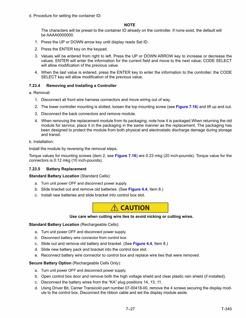
7–27 T-340
d. Procedure for setting the container ID:
NOTEThe characters will be preset to the container ID already on the controller. If none exist, the default willbe AAAA0000000.
1. Press the UP or DOWN arrow key until display reads Set ID.
2. Press the ENTER key on the keypad.
3. Values will be entered from right to left. Press the UP or DOWN ARROW key to increase or decrease thevalues. ENTER will enter the information for the current field and move to the next value; CODE SELECTwill allow modification of the previous value.
4. When the last value is entered, press the ENTER key to enter the information to the controller; the CODESELECT key will allow modification of the previous value.
7.23.4 Removing and Installing a Controller
a. Removal:
1. Disconnect all front wire harness connectors and move wiring out of way.
2. The lower controller mounting is slotted, loosen the top mounting screw (see Figure 7.16) and lift up and out.
3. Disconnect the back connectors and remove module.
4. When removing the replacement module from its packaging, note how it is packaged.When returning the oldmodule for service, place it in the packaging in the same manner as the replacement. The packaging hasbeen designed to protect the module from both physical and electrostatic discharge damage during storageand transit.
b. Installation:
Install the module by reversing the removal steps.
Torque values for mounting screws (item 2, see Figure 7.16) are 0.23 mkg (20 inch-pounds). Torque value for theconnectors is 0.12 mkg (10 inch-pounds).
7.23.5 Battery Replacement
Standard Battery Location (Standard Cells):
a. Turn unit power OFF and disconnect power supply.
b. Slide bracket out and remove old batteries. (See Figure 4.4, Item 8.)
c. Install new batteries and slide bracket into control box slot.
CAUTION!Use care when cutting wire ties to avoid nicking or cutting wires.
Standard Battery Location (Rechargeable Cells):
a. Turn unit power OFF and disconnect power supply.
b. Disconnect battery wire connector from control box.
c. Slide out and remove old battery and bracket. (See Figure 4.4, Item 8.)
d. Slide new battery pack and bracket into the control box slot.
e. Reconnect battery wire connector to control box and replace wire ties that were removed.
Secure Battery Option (Rechargeable Cells Only):
a. Turn unit power OFF and disconnect power supply.
b. Open control box door and remove both the high voltage shield and clear plastic rain shield (if installed).
c. Disconnect the battery wires from the “KA” plug positions 14, 13, 11.
d. Using Driver Bit, Carrier Transicold part number 07-00418-00, remove the 4 screws securing the display mod-ule to the control box. Disconnect the ribbon cable and set the display module aside.
T-340 7–28
NOTEThe battery wires must face toward the right.
e. Remove the old battery from the bracket and clean bracket surface. Remove the protective backing from thenew battery and assemble to the bracket. Secure battery by inserting the wire tie from the back of thebracket around the battery, and back through the bracket.
f. Reconnect the ribbon cable to display and re- install the display.
g. Route the battery wires from the battery along the display harness and connect the red battery wire and oneend of the red jumper to “KA14,” the other end of the red jumper wire to “KA11,” and the black wire to“KA13.”
h. Replace wire ties that were removed.
7.24 TEMPERATURE SENSOR SERVICE
Service procedures for the return recorder, return temperature, supply recorder, supply temperature, ambient,defrost temperature, evaporator temperature, and compressor discharge temperature sensors are provided in thefollowing sub-paragraphs.
7.24.1 Sensor Checkout Procedure
To verify that accuracy of a temperature sensor:
a. Remove the sensor and place in a 0°C (32°F) ice-water bath. The ice-water bath is prepared by filling aninsulated container (of sufficient size to completely immerse bulb) with ice cubes or chipped ice, then fillingvoids between ice with water and agitating until mixture reaches 0°C (32°F) measured on a laboratory ther-mometer.
b. Start unit and check sensor reading on the control panel. The reading should be 0°C (32°F). If the reading iscorrect, reinstall sensor; if it is not, continue with the following.
c. Turn unit OFF and disconnect power supply.
d. Refer to Section 7.23 and remove controller to gain access to the sensor plugs.
e. Using the plug connector marked “EC” that is connected to the back of the controller, locate the sensorwires (RRS, RTS, SRS, STS, AMBS, DTS, or CPDS as required). Follow those wires to the connector andusing the pins of the plug, measure the resistance. Values are provided in Table 7–2 and Table 7–3.
Due to the variations and inaccuracies in ohmmeters, thermometers or other test equipment, a readingwithin 2% of the chart value would indicate a good sensor. If a sensor is defective, the resistance reading willusually be much higher or lower than the resistance values given.

7–29 T-340
Table 7–2 Sensor Resistance
Sensors AMBS, DTS, ETS, RRS, RTS, SRS, STS
°C °F Ohms °C °F Ohms °C °F Ohms °C °F Ohms
-40 -40 336,500 -7.8 18 49,060 24.4 76 10,250 56.7 134 2,809
-38.9 -38 312,600 -6.7 20 46,230 25.6 78 9,760 57.8 136 2,697
-37.8 -36 290,600 -5.6 22 43,580 26.7 80 9,299 58.9 138 2,590
-36.7 -34 270,300 -4.4 24 41,100 27.8 82 8,862 60.0 140 2,488
-35.6 -32 251,500 -3.3 26 38,780 28.9 84 8,449 61.1 142 2,390
-34.4 -30 234,200 -2.2 28 36,600 30.0 86 8,057 62.2 144 2,297
-33.3 -28 218,200 -1.1 30 34,560 31.1 88 7,686 63.3 146 2,208
-32.2 -26 203,400 0 32 32,650 32.2 90 7,334 64.4 148 2,124
-31.1 -24 189,700 1.1 34 30,850 33.3 92 7,000 65.6 150 2,042
-30 -22 177,000 2.2 36 29,170 34.4 94 6,684 68.3 155 1,855
-28.9 -20 165,200 3.3 38 27,590 35.6 96 6,384 71.1 160 1,687
-27.8 -18 154,300 4.4 40 26,100 36.7 98 6,099 73.9 165 1,537
-26.7 -16 144,200 5.5 42 24,700 37.8 100 5,828 76.7 170 1,402
-25.6 -14 134,800 6.6 44 23,390 38.9 102 5,571 79.4 175 1,281
-24.4 -12 126,100 7.7 46 22,160 40.0 104 5,327 82.2 180 1,171
-23.3 -10 118,100 8.9 48 20,990 41.1 106 5,095 85.0 185 1,072
-22.2 -8 110,500 10 50 19,900 42.2 108 4,874 87.8 190 983
-21.1 -6 103,600 11.1 52 18,870 43.3 110 4,665 90.6 195 902
-20 -4 97,070 12.2 54 17,900 44.4 112 4,465 93.3 200 829
-18.9 -2 91,030 13.3 56 16,980 45.5 114 4,275 96.1 205 762
-17.8 0 85,400 14.4 58 16,120 46.7 116 4,095 98.9 210 702
-16.7 2 80,160 15.5 60 15,310 47.8 118 3,923 101.7 215 647
-15.6 4 75,270 16.6 62 14,540 48.9 120 3,759 104.4 220 598
-14.4 6 70,720 17.7 64 13,820 50.0 122 3,603 107.2 225 553
-13.3 8 66,460 18.9 66 13,130 51.1 124 3,454 110.0 230 511
-12.2 10 62,500 20.0 68 12,490 52.2 126 3,313 112.8 235 473
-11.1 12 58,790 21.1 70 11,880 53.3 128 3,177 115.6 240 438
-10.0 14 55,330 22.2 72 11,310 54.4 130 3,049 118.3 245 406
-8.9 16 52,090 23.3 74 10,760 55.6 132 2,926 121.1 250 378

T-340 7–30
Table 7–3 Sensor Resistance (CPDS)
°C °F Ohms °C °F Ohms °C °F Ohms
-40 -40 2,889,600 38 100.4 49,656 116 240.8 3,759
-38 -36.4 2,532,872 40 104.0 45,812 118 244.4 3,550
-36 -32.8 2,225,078 42 107.6 42,294 120 248.0 3,354
-34 -29.2 1,957,446 44 111.2 39,078 122 251.6 3,173
-32 -25.6 1,724,386 46 114.8 36,145 124 255.2 3,004
-30 -22.0 1,522,200 48 118.4 33,445 126 258.8 2,850
-28 -18.4 1,345,074 50 122.0 30,985 128 262.4 2,711
-26 -14.8 1,190,945 52 125.6 28,724 130 266.0 2,580
-24 -11.2 1,056,140 54 129.2 26,651 132 269.6 2,454
-22 -7.6 938,045 56 132.8 27,750 134 273.2 2,335
-20 -4.0 834,716 58 136.4 23,005 136 276.8 2,223
-18 -0.4 743,581 60 140.0 21,396 138 280.4 2,119
-16 3.2 663,593 62 143.6 19,909 140 284.0 2,021
-14 6.8 593,030 64 147.2 18,550 142 287.6 1,928
-12 10.4 530,714 66 150.8 17,294 144 291.2 1,839
-10 14.0 475,743 68 154.4 16,133 146 294.8 1,753
-8 17.6 426,904 70 158.0 15,067 148 298.4 1,670
-6 21.2 383,706 72 161.6 14,078 150 302.0 1,591
-4 24.8 345,315 74 165.2 13,158 152 305.6 1,508
-2 28.4 311,165 76 168.8 12,306 154 309.2 1,430
0 32.0 280,824 78 172.4 11,524 156 312.8 1,362
2 35.6 253,682 80 176.0 10,793 158 316.4 1,302
4 39.2 229,499 82 179.6 10,122 160 320.0 1,247
6 42.8 207,870 84 183.2 9,494 162 323.6 1,193
8 46.4 188,494 86 186.8 8,918 164 327.2 1,142
10 50.0 171,165 88 190.4 8,376 166 330.8 1,096
12 53.6 155,574 90 194.0 7,869 168 334.4 1,054
14 57.2 141,590 92 197.6 7,404 170 338.0 1,014
16 60.8 129,000 94 201.2 6,972 172 341.6 975
18 64.4 117,656 96 204.8 6,571 174 345.2 938
20 68.0 107,439 98 208.4 6,197 176 348.8 902
22 71.6 98,194 100 212.0 5,848 178 352.4 867
24 95.2 89,916 102 215.6 5,529 180 356.0 834
26 78.8 82,310 104 219.2 5,233 182 359.6 798
28 82.4 75,473 106 222.8 4,953 184 363.2 764
30 83.0 69,281 108 226.4 4,692 186 366.8 733
32 89.6 63,648 110 230.0 4,446 188 370.4 706
34 93.2 58,531 112 233.6 4,204 190 374.0 697
36 96.8 53,887 114 237.2 3,977

7–31 T-340
7.24.2 Sensor Replacement
a. Turn unit power OFF and disconnect power supply.
NOTEInclude white date code label when cutting out and removing defective sensors. The label could berequired for warranty returns.
b. Cut cable. Slide the cap and grommet off a bulb type sensor and save for reuse. Do not cut the grommet.
c. Cut one wire of existing cable 40 mm (1-1/2 inches) shorter than the other wire.
d. Cut replacement sensor wires (opposite colors) back 40 mm (1-1/2 inches). (See Figure 7.17.)
Figure 7.17 Sensor Types
1. Sensor
2. 40 mm (1 1/2 in), 2 or 3 wires as required
3. 6.3 mm (1/4 in).
- - - - -
e. Strip back insulation on all wiring 6.3 mm (1/4 inch).
f. Slide a large piece of heat shrink tubing over the cable, and place the two small pieces of heat shrink tubing,one over each wire, before adding crimp fittings as shown in Figure 7.18.
Figure 7.18 Sensor and Cable Splice
1. Cable2. Sensor (Typical)
3. Large Heat Shrink Tubing (1)4. Heat Shrink Tubing, 2 or 3 as required
- - - - -
Mounting Stud Type
Bulb Type
1
1
2
2
3
3
1
2
3 4

T-340 7–32
g. If required, slide the cap and grommet assembly onto the replacement sensor.
h. Slip crimp fittings over dressed wires (keeping wire colors together). Make sure wires are pushed into crimpfittings as far as possible and crimp with crimping tool.
i. Solder spliced wires with a 60% tin and 40% lead Rosincore solder.
j. Slide heat shrink tubing over each splice so that ends of tubing cover both ends of crimp as shown in Figure 7.18.
k. Heat tubing to shrink over splice. Make sure all seams are sealed tightly against the wiring to prevent mois-ture seepage.
CAUTION!Do not allow moisture to enter wire splice area as this may affect sensor resistance.
l. Slide large heat shrink tubing over both splices and shrink.
m. Position sensor in unit as shown in Figure 7.18 and re-check sensor resistance.
n. Reinstall sensor (refer to Section 7.24.3).
NOTEThe P5 Pre-Trip test must be run to deactivate probe alarms (refer to Section 5.9).
7.24.3 Sensors Re-Installation
Sensors STS and SRS
To properly position a supply sensor, the sensor must be fully inserted into the probe holder mounting clamp. SeeFigure 7.19. Do not allow heat shrink covering to contact the probe holder. For proper placement of the sensor, besure to position the enlarged positioning section of the sensor against the side of the mounting clamp. This position-ing will give the sensor the optimum amount of exposure to the supply air stream, and will provide accurate tempera-ture readings to the controller.
Sensors RRS and RTS
Reinstall the return sensor as shown in Figure 7.20. For proper placement of the return sensor, be sure to positionthe enlarged positioning section of the sensor against the side of the mounting clamp.
Sensor DTS
The DTS sensor must have insulating material placed completely over the sensor to ensure the coil metal tempera-ture is sensed.
Sensors ETS1 and ETS2
The ETS1 and ETS2 sensors are located in a tube holder under insulation, as illustrated in Figure 7.21. When thecombo sensor is removed and reinstalled, it must be placed in a tube holder by applying thermal grease. Insulatingmaterial must completely cover the sensor to ensure the correct temperature is sensed.

7–33 T-340
Figure 7.19 Supply Sensor Positioning
1. Supply Air Stream2. Insulation3. Back Panel4. Supply Sensor5. Mounting Clamp6. Sensor Wires7. Drip Loop
8. Gasket Mounting Plate9. Gasketed Support Plate10. Gasketed Cover11. TIR Bolts12. STS Probe13. SRS Probe
- - - - -
Figure 7.20 Return Sensor Positioning
1. Mounting Clamp2. Return Sensor
- - - - -
Figure 7.21 Evaporator Temp Sensor Positioning
1. Wire Tie
2. ETS1 and 2
3. ETS Tube Holder
4. Insulation
- - - - -
(2.5”)
1
2
3
4
5
7
6
8
9
10
11
12
13
1.50 in.(38.1cm)
1 21.00 in.(25.4cm)
1
23
4

T-340 7–34
Sensor, CPDS
To replace the Compressor Discharge Temperature Sensor, see Figure 7.22:
a. Ensure the unit is disconnected from the power source and that ST is in OFF position.
b. Remove the existing sensor. Clean all silicone sealer and dielectric compound from the sensor well. Ensurewell is clean and dry. The top of the compressor, where the sensor seals, must also be clean and dry.
Figure 7.22 Compressor Discharge Temperature Sensor
c. Using the syringe supplied with the replacement sensor, squeeze all of the dielectric compound into the sen-sor well.
d. Place a bead of the silicone sealer supplied with the replacement sensor around the sensor sealing ring.Insert sensor into the well with the leads parallel to the suction fitting.
e. Reconnect the sensor (see Figure 7.18) and run Pre-trip P5.
7.25 VENT POSITION SENSOR (VPS)
The vent position sensor (VPS) determines the position of the fresh air vent in near real-time via the Cd55.
The fresh air vent position sensor alarm (AL50) will occur if the sensor reading is not stable for four minutes or if thesensor is outside of its valid range (shorted or open). This can occur if the vent is loose or the panel is defective. Toconfirm a defective panel, assure that the wing nut is secure and then power cycle the unit. If the alarm immedi-ately reappears as active, the panel should be replaced.
The alarm should immediately go inactive, check the 4-minute stability requirement. If the alarm reoccurs after thefour minutes and the panel was known to have been stable, then the sensor should be replaced.
Upper VPS:
In order to replace the Upper VPS, the panel must be removed and replaced with another upper fresh air panelequipped with VPS.
Upon installation, a new VPS assembly requires calibration as follows:
1. Rotate the vent to the 0 CMH / CFM position.
2. Cd45 will automatically display. Press the Enter key and hold for five seconds.
3. After the enter key has been pressed the display will read CAL (for calibration).
4. Press the ALT MODE key and hold for five seconds.
5. After the calibration has been completed, Cd45 will display 0 CMH / CFM.
SENSOR WELL
SENSOR
SILICONE BEAD
7–35 T-340
Lower VPS:
Calibration of the Lower VPS is only required when the air makeup slide, motor or sensor has been repaired or serviced.
The VPS is calibrated using the keypad:
1. Remove the two nuts that secure the air makeup panel slide to the unit.
2. Rotate the gear clockwise until it stops.
3. Rotate the gear 1/4 turn counterclockwise.
4. Carefully reposition the slide onto the air makeup panel, given that the gear is engaged with the rail and hasnot moved.
5. Position slide panel to the fully closed position.
6. Cd45 will automatically be shown on the left display.
7. Depress the ENTER key and hold for five seconds. CAL for calibration is displayed.
8. Depress the ALT MODE key on the keypad and hold for five seconds.
9. When calibration has been completed, Cd45 causes 0 CMH/CFM to be shown on the right display.
10. Secure the air makeup panel slide to the unit with the two nuts; stake threads.
7.26 EAUTOFRESH SERVICE
7.26.1 Servicing the eAutoFresh Air Filter
Removing the Air Sample Filter Element
The air sample filter element can be accessed in two ways:
1. Through the eAutoFresh side evaporator access panel (item 11, Figure 3.2).
2. Through the inside of the container by lowering the upper evaporator panel.
a. By hand, unscrew and remove the filter cup from the bottom of the air sample filter assembly.
b. Remove the filter element from the filter assembly.
c. Install the new air sample filter element by reversing the above steps.
7.26.2 Checking eAutoFresh Drive System
Checking the Auto Slide:
a. To check with an ohmmeter, disconnect the four pin connector to the stepper motor. With a reliable digitalohmmeter, check the winding resistance. In normal ambient, the motor should have 72 to 84 ohms mea-sured on the red/green (a-b terminals) and on the white/black (c-d terminals) leads. If an infinite or zeroreading occurs, check connections or replace the motor. If near normal or normal reading occurs, proceedto the following sections to check out the controller.
b. To check with a SMA-12 portable stepper drive tester. The SMA-12 portable stepper drive tester (CarrierTransicold P/N 07-00375-00) is a battery operated stepper drive which will open and close the auto slide,which allows a more thorough check of the motor.
Checking the Slide Motor:
a. Turn unit OFF.
b. Disconnect the four pin connector from the Stepper Drive to the Stepper Motor, (see Figure 7.23).
c. Attach the SMA-12 portable stepper drive tester to the Stepper Motor.
d. Set the SMA-12 pulse per second (PPS) to one PPS and press button to open or close the valve. Each LEDshould light sequentially until all four are lit. If an LED fails to light, it indicates an open on that leg caused bya poor connection or an open coil. Repair or replace as required to achieve proper operation.

T-340 7–36
Figure 7.23 Stepper Components
e. Set the SMA-12 step rate to 200 PPS. Press open or close while watching the slide mechanism for move-ment, this is an indication that the motor is working.
f. If the slide moves using the SMA-12, but fails to move when connected in the unit (refer to “Checking the DriveModule” in the section that follows.)
Checking the Drive Module:
a. Turn unit OFF.
b. Disconnect the four pin connector to the Stepper Motor.
c. With a voltmeter set to read 24 volts AC, attach the positive lead to the drive module outlet pin A (wire 1A) ofthe four pin connector and the negative lead to the B pin (wire 1B).
d. Turn ON unit, and watch the volt meter. After a short delay, the reading should rise to approximately 12 volts.
e. Repeat for pins C and D (wires 2A and 2B).
f. If only one set of pins reads a voltage, check connections and retest.
g. If the retest reads out the same, the drive module or controller is faulty.
h. If no voltage is present in any step, the output from the controller to the drive module may be faulty. Checkthe connections and wires from the controller to the drive module.
i. To replace the drive module, disconnect all connectors, unscrew from mounting, and replace with a NEWdrive module in reverse order.
7.26.3 Checking the Controller
a. Turn the unit OFF.
b. Disconnect the six pin connector to the stepper drive from the controller.
c. With a voltmeter set to read 50 volts DC, attach the positive lead to outlet pin A of the six pin connector, andthe negative lead to pin B or TP-9 of the controller.
d. Turn ON the unit for 40 seconds, and watch the voltmeter. There should be approximately 24 to 32 VDCshown on pin A.
e. There should be zero volts on pin B.
f. After a short delay, the reading should rise to approximately 24 to 32 VDC on pin E.
g. Pins C and D will have zero to 5 volts transistor logic (TTL) signals present, however, this can only be checkedwith the connector assembled as this is an open collector type circuit.
Checking the outputs on A, B and E will verify that the controller is supplying power to the drive module. To be thor-ough, and if it is desired, the signals on pins C and D can be checked as follows:
h. Install a jumper assembly (Carrier part number 07-00408-00) to connect the drive module and controllerconnectors as shown in Figure 7.24.
i. Connect the positive lead of the voltmeter to test connector socket C and negative lead to socket B, and runas before by resetting unit.
j. Repeat for sockets D and B.
Stepper Drive (SD) Stepper Motor (AF)

7–37 T-340
Figure 7.24 Jumper Assembly
There should be approximately five volts DC on sockets “C” and “D” (S1 andS2) when measured as above. If notthe connections or controller is faulty. If any of these pins are not consistent, the connections or the controller issuspect. Check and replace as required.
7.26.4 Servicing the eAutoFresh Drive System
To replace the Drive Motor Assembly:
a. Remove the bolts that secure the eAutoFresh Panel (3, Figure 7.25) to the front of the unit. Reach in, cut tiewrap, (2) and disconnect the motor connector (1). Bring panel to work area.
b. Remove four screws (8) fastening the grille (7).
c. Remove six screws (9) fastening the rails (5 and 11), the slide plate (10) and the gasket plate (6). Set com-ponents aside for reassembly.
d. Remove the four screws (12) fastening the motor cup (4) to the panel. Cut sealer on outside and inside ofmotor cup assembly. Push out the motor cup assembly from the rear of the panel.
e. Mount the replacement motor cup assembly in the panel using original screws. Torque screws to 0.29 mkg(25 +/- 1 Inch pounds).
f. Reapply sealer to the inside and the outside of the motor cup assembly.
g. Mount the upper & lower rails, slide plate and gasket plate using original hardware. Apply thread sealantand torque screws to 0.29 mkg (25 +/- 1 Inch pounds).
h. Mount grille assembly using original hardware. Apply thread sealant and torque screws to 0.29mkg (25 +/- 1Inch pounds).
i. Reconnect the motor connector.
j. Replace the bolts that secure the eAutoFresh Panel to the front of the unit.
k. Carry out functional test.Refer to Section 5.4.3 step c.
A
B
C
D
E
A
BC
D
E
ControllerConnector (EC)
Drive ModuleConnector (SD)
JumperTest
Connector

T-340 7–38
Figure 7.25 Motor Cup Replacement
1. Connector2. Tie Wrap3. eAutoFresh Panel4. Cup, Motor5. Rail, Top6. Plate, Gasket
7. Grille8. Grill Screws9. Rail Screws10. Plate, Slide11. Rail, Bottom12. Motor Cup Screws
- - - - -
7.27 ELECTRONIC PARTLOW TEMPERATURE RECORDER
The microprocessor-based temperature recorder is designed to interface with the DataCORDER to log tempera-ture with time. The electronic recorder will automatically record the return air, supply air, or both, based on the set-ting of temperature controller configuration code CnF37, refer to Table 4–4. The recorder reads and records datafrom the controller in present time, under normal operating conditions.
1 2
1
3
4
56 7 8
91011
12

7–39 T-340
If the power has been OFF for more than thirty days, the recorder will NOT re-synchronize (the chart will notadvance to present time), the pen tip will move to the currently recorded temperature, and the recorder will resumenormal temperature recording.
NOTICEIf using the Electronic Partlow Recorder CTD part number 12-00464-xx,
Where xx= an even number (example: 12-00464-08)
The recorder will STOP when the power is OFF, and the pen tip will remain at the last recorded temperature on thechart. When power is applied, and the power off period is less than thirty days, the recorder will retrieve the loggeddata from the DataCORDER for the power off period and record it onto the chart. Thereafter, the recorder willresume normal temperature recording.
If the optional DataCORDER battery pack is being used and the charge is too low to enable recording during thepower off period of less than thirty days, the pen tip will move to below the inner chart ring for the period when NOdata was recorded by the DataCORDER.
7.27.1 Replacing the Recorder
a. Turn power to the unit OFF.
b. Open the recorder door (item 1, see Figure 7.26).
c. Locate the connector below the recorder (item 6), and squeeze the ears together to disconnect the plug.
d. Remove the four mounting screws (item 8), and remove the recorder.
e. Install the new recorder by reversing the above steps.
Figure 7.26 Electronic Partlow Temperature Recorder
1. Recorder Door2. Change Chart Button3. Recorder Box4. Pen Tip5. Stylus Arm
6. Connector7. Calibration Button (Located underneath)8. Mounting Screws, #10-24 x 7/16 inches long9. Hold Down Tab10. Chart Retaining Nut
- - - - -
1
2
3
4
5
6
7
8
9
10

T-340 7–40
7.27.2 Recalibrating the Temp Recorder to Zero
For Electronic Partlow Recorder CTD part number 12-00464-xx, Where xx= an odd number (example: 12-00464-03)
NOTEUse chart CTD: part number 09-00128-00 (F), part number 09-00128-01 (C).
a. Press the “Calibration” button (item 7, Figure 7.26) on the bottom of the recorder. The pen tip will drive fullydown scale, then move upscale to the chart ring at -29°C (-20°F), and stop.
b. If the tip of the pen (item 4) is on the -29°C (-20°F) chart ring, the recorder is in calibration, proceed to stepc. If the tip of the pen is NOT on the -29°C (-20°F) chart ring, the operator must loosen the two screws onthe bottom of the stylus arm to adjust the pen tip manually to the -29°C (-20°F) chart ring. Tighten thescrews when adjustment is complete.
c. Press the calibration button and the pen will position itself to the correct temperature reading.
For Electronic Partlow Recorder CTD part number 12-00464-xxWhere xx= an even number (example: 12-00464-08)
NOTEUse chart CTD part number 09-00128-00 (F), part number 09-00128-01 (C).
a. Press the “Calibration” button (item 7, Figure 7.26) on the bottom of the recorder. The pen tip will drive fullydown scale, then move upscale to the chart ring at 0C (32F), and stop.
b. If the tip of the pen (item 4) is on the 0°C (32°F) chart ring the recorder is in calibration, proceed to step c. Ifthe tip of the pen is NOT on the 0°C (32°F) chart ring, the operator must loosen the two screws on the bot-tom of the stylus arm to adjust the pen tip manually to the 0°C (32°F) chart ring. Tighten the screws whenadjustment is complete.
c. Press the calibration button and the pen will position itself to the correct temperature reading.
7.28 MAINTENANCE OF PAINTED SURFACES
The refrigeration unit is protected by a special paint system against the corrosive atmosphere in which it normallyoperates. However, should the paint system be damaged, the base metal can corrode. In order to protect the refrig-eration unit from the highly corrosive sea atmosphere, or if the protective paint system is scratched or damaged,clean the area to bare metal using a wire brush, emery paper or equivalent cleaning method. Immediately followingcleaning, apply paint to the area, and allow to dry. Refer to the Parts List for proper paint selection.
7.29 COMMUNICATIONS INTERFACE MODULE INSTALLATION
Figure 7.27 Communications Interface Installation
Units that have been factory provisioned for installation of a Communication Interface Module (CIM) have therequired wiring installed. If the unit is not factory provisioned, a provision wiring kit (Carrier Transicold part number76-00685-00) must be installed. Installation instructions are packaged with the kit.
CommunicationsInterface Module
CB1

7–41 T-340
To install the module:
WARNING!Installation requires wiring to the main unit circuit breaker, CB1.Make sure the power to theunit is off and power plug disconnected before beginning installation.
a. CB1 is connected to the power system, see wiring schematic. Ensure that the unit power is off AND that theunit power plug is disconnected.
b. Open control box, (see Figure 7.27) and remove low voltage shield. Open high voltage shield.
c. If using factory provisioned wiring, remove the circuit breaker panel, with circuit breaker, from the controlbox. Locate, wires CB21/CIA3, CB22/CIA5 and CB23/CIA7 that have been tied back in the wire harness.Remove the protective heat shrink from the ends of the wires.
d. Refit the circuit breaker panel.
e. Fit the new CIM into the unit.
f. Attach three wires CB21/CIA3, CB22/CIA5 and CB23/CIA7 to the CIM at connection CIA.
g. Locate connectors CIA and CIB, remove plugs if required, and attach to the module.
h. Replace the low voltage shield.
Table 7–4 Recommended Bolt Torque Values (Dry, Non-Lubricated for 18-8 Stainless Steel)
BOLT DIA. THREADS in-lb ft-lb N-m
Free Spinning
#4 40 5.2 0.4 0.6
#6 32 9.6 0.8 1.1
#8 32 20 1.7 2.3
#10 24 23 1.9 2.6
1/4 20 75 6.3 8.5
5/16 18 132 11 14.9
3/8 16 240 20 27.1
7/16 14 372 31 42
1/2 13 516 43 58.3
9/16 12 684 57 77.3
5/8 11 1104 92 124.7
3/4 10 1488 124 168.1
Non Free Spinning (Locknuts etc.)
1/4 20 82.5 6.9 9.3
5/16 18 145.2 12.1 16.4
3/8 16 264 22.0 29.8
7/16 14 409.2 34.1 46.2
1/2 13 567.6 47.3 64.1
9/16 12 752.4 62.7 85
5/8 11 1214.4 101.2 137.2
3/4 10 1636.8 136.4 184.9
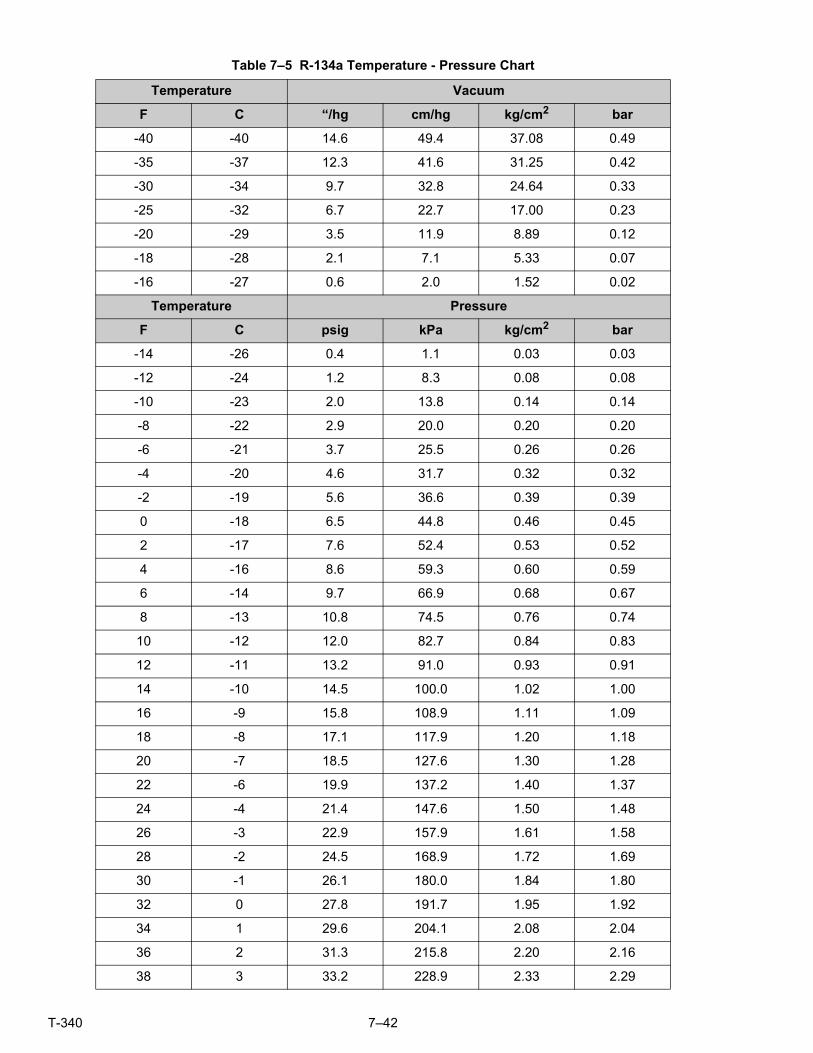
T-340 7–42
Table 7–5 R-134a Temperature - Pressure Chart
Temperature Vacuum
F C “/hg cm/hg kg/cm2 bar
-40 -40 14.6 49.4 37.08 0.49
-35 -37 12.3 41.6 31.25 0.42
-30 -34 9.7 32.8 24.64 0.33
-25 -32 6.7 22.7 17.00 0.23
-20 -29 3.5 11.9 8.89 0.12
-18 -28 2.1 7.1 5.33 0.07
-16 -27 0.6 2.0 1.52 0.02
Temperature Pressure
F C psig kPa kg/cm2 bar
-14 -26 0.4 1.1 0.03 0.03
-12 -24 1.2 8.3 0.08 0.08
-10 -23 2.0 13.8 0.14 0.14
-8 -22 2.9 20.0 0.20 0.20
-6 -21 3.7 25.5 0.26 0.26
-4 -20 4.6 31.7 0.32 0.32
-2 -19 5.6 36.6 0.39 0.39
0 -18 6.5 44.8 0.46 0.45
2 -17 7.6 52.4 0.53 0.52
4 -16 8.6 59.3 0.60 0.59
6 -14 9.7 66.9 0.68 0.67
8 -13 10.8 74.5 0.76 0.74
10 -12 12.0 82.7 0.84 0.83
12 -11 13.2 91.0 0.93 0.91
14 -10 14.5 100.0 1.02 1.00
16 -9 15.8 108.9 1.11 1.09
18 -8 17.1 117.9 1.20 1.18
20 -7 18.5 127.6 1.30 1.28
22 -6 19.9 137.2 1.40 1.37
24 -4 21.4 147.6 1.50 1.48
26 -3 22.9 157.9 1.61 1.58
28 -2 24.5 168.9 1.72 1.69
30 -1 26.1 180.0 1.84 1.80
32 0 27.8 191.7 1.95 1.92
34 1 29.6 204.1 2.08 2.04
36 2 31.3 215.8 2.20 2.16
38 3 33.2 228.9 2.33 2.29

7–43 T-340
40 4 35.1 242.0 2.47 2.42
45 7 40.1 276.5 2.82 2.76
50 1 45.5 313.7 3.20 3.14
55 13 51.2 353.0 3.60 3.53
60 16 57.4 395.8 4.04 3.96
65 18 64.1 441.0 4.51 4.42
70 21 71.1 490.2 5.00 4.90
75 24 78.7 542.6 5.53 5.43
80 27 86.7 597.8 6.10 5.98
85 29 95.3 657.1 6.70 6.57
90 32 104.3 719.1 7.33 7.19
95 35 114.0 786.0 8.01 7.86
100 38 124.2 856.4 8.73 8.56
105 41 135.0 930.8 9.49 9.31
110 43 146.4 1009 10.29 10.09
115 46 158.4 1092 11.14 10.92
120 49 171.2 1180 12.04 11.80
125 52 184.6 1273 12.98 12.73
130 54 198.7 1370 13.97 13.70
135 57 213.6 1473 15.02 14.73
140 60 229.2 1580 16.11 15.80
145 63 245.6 1693 17.27 16.93
150 66 262.9 1813 18.48 18.13
155 68 281.1 1938 19.76 19.37
Table 7–5 R-134a Temperature - Pressure Chart
Temperature Vacuum


8–1 T-340
SECTION 8
ELECTRICAL WIRING SCHEMATICS
8.1 INTRODUCTION
This section contains the Electrical Schematics and Wiring Diagrams. The diagrams are presented as follows:
Figure 8.1 provides the legend for use with Figure 8.2, the schematic diagram for standard refrigeration units.
Figure 8.2 provides the basic schematic diagram for standard refrigeration units.
Figure 8.3 provides the legend for use with Figure 8.4, the schematic diagram for units with available optionsexcept Vent Positioning System, eAutoFresh and Emergency Bypass.
Figure 8.4 provides the basic schematic diagram for units with available options except Vent Positioning System,eAutoFresh and Emergency Bypass.
Figure 8.5 provides the legend for use with Figure 8.6, the schematic diagram for units with eAutoFresh and/orEmergency Bypass.
Figure 8.6 provides the basic schematic diagram for units with units with eAutoFresh and/or Emergency Bypass.
Figure 8.7 supplements Figure 8.4 and Figure 8.6 and provides schematic and wiring diagrams for Upper VentPosition Sensor (VPS).
Figure 8.8 supplements Figure 8.4 and Figure Figure 8.6 and provides schematic and wiring diagrams for LowerVPS.
NOTEOptions other than those mentioned below may be included in wiring diagrams.
Figure 8.9 provides the wiring diagram for standard refrigeration units with 3-phase condenser fan motors.
Figure 8.10 provides the wiring diagram for units with Single Phase condenser fan motors and/or optional 5+1heater arrangement.
Figure 8.11 provides the wiring diagram for units with eAutoFresh and/or Emergency Bypass installed.

T-340 8–2
Figure 8.1 LEGEND − Standard Unit Configuration
SYMBOL DESCRIPTION
AMBS AMBIENT SENSOR (C 21)
C CONTROLLER (J 19)
CB1 CIRCUIT BREAKER 460 VOLT (F 1)
CF CONDENSER FAN CONTACTOR (M 11, P 6)
CH COMPRESSOR CONTACTOR (M 7, P 1)
CI COMMUNICATIONS INTERFACE MODULE (OPTION) (A 3)
CM CONDENSER FAN MOTOR (H 10, T 6)
CP COMPRESSOR MOTOR (T 1)
CPDS DISCHARGE TEMPERATURE SENSOR (B 21)
CS CURRENT SENSOR (J 2)
DHBL DEFROST HEATER BOTTOM LEFT (R 5)
DHBR DEFROST HEATER BOTTOM RIGHT (T 4)
DHML DEFROST HEATER MIDDLE LEFT (R 4)
DHMR DEFROST HEATER MIDDLE RIGHT (T 4)
DHTL DEFROST HEATER TOP LEFT (R 4)
DHTR DEFROST HEATER TOP RIGHT (T 5)
DPT DISCHARGE PRESSURE TRANSDUCER (J 21)
DTS DEFROST TEMPERATURE SENSOR (C 21)
DUV DIGITAL UNLOADER VALVE (E 22)
EEV ELECTRONIC EXPANSION VALVE (P 15)
EF EVAPORATOR FAN CONTACTOR HIGH SPEED (N 8, M 12)
EM EVAPORATOR FAN MOTOR (D 15, F 12, T 7, T 10)
EPT EVAPORATOR PRESSURE TRANSDUCER (G 21)
ES EVAPORATOR FAN CONTACTOR LOW SPEED(M 11, P 7)
ETS EVAPORATOR TEMPERATURE SENSOR(D 16, D 21)
ESV ECONOMIZER SOLENOID VALVE (K 9)
F FUSE (C 6, D 6, D 18, E 18)
FLA FULL LOAD AMPS
HPS HIGH PRESSURE SWITCH (G 7)
LEGEND
SYMBOL DESCRIPTION
HR HEATER CONTACTOR (P 4, M 13)
HS HUMIDITY SENSOR (F 21)
HTT HEAT TERMINATION THERMOSTAT (G 13)
ICF INTERROGATOR CONNECTOR FRONT (T 21)
ICR INTERROGATOR CONNECTOR REAR (T 22)
IP INTERNAL PROTECTOR (E 12, H 10, H 12)
PA UNIT PHASE CONTACTOR (L 1, M 6)
PB UNIT PHASE CONTACTOR (L 3, M 3)
PR USDA PROBE RECEPTACLE (E 21, L 22, M 22)
RM REMOTE MONITORING RECEPTACLE (OPTION)(L 6, M 6, L 11, M 11, L 14, M 14)
RRS RETURN RECORDER SENSOR (C 21)
RTS RETURN TEMPERATURE SENSOR (B 21)
SPT SUCTION PRESSURE TRANSDUCER (G 21)
SRS SUPPLY RECORDER SENSOR (K 21)
ST START STOP SWITCH (G 4, G 5)
STS SUPPLY TEMPERATURE SENSOR (A 21)
TC CONTROLLER RELAY COOLING (H 7)
TCP CONTROLLER RELAY COMPRESSOR PHASE SEQUENCING (K 6, K 7)
TE CONTROLLER RELAY HIGH SPEED EVAPORATORFANS (K 12)
TH CONTROLLER RELAY HEATING (K 13)
TN CONTROLLER RELAY CONDENSER FAN (K 10)
TP TEST POINT (F 8, F 9, H 7, J 10, J 12, M 15)
TQ CONTROLLER RELAY LIQUID INJECTION (OPTION)(E 9)
TR TRANSFORMER (H 3)
TS CONTROLLER RELAY ECONOMIZER SOLENOIDVALVE (E 9)
TV CONTROLLER RELAY LOW SPEED EVAPORATORFANS (J 11)
WCR WETTING CURRENT RESISTOR (H 10)
WP WATER PRESSURE SWITCH (D 10)

8–3 T-340
Figure 8.2 SCHEMATIC DIAGRAM − Standard Unit Configuration
Based on Drawing 62 −11271 Rev A

T-340 8–4
Figure 8.3 LEGEND − Configuration With Available Options
(Except Vent Positioning System, eAutoFresh, Emergency Bypass Options)
SYMBOL DESCRIPTION
AMBS AMBIENT SENSOR (C 21)
C CONTROLLER (J 19)
CB1 CIRCUIT BREAKER 460 VOLT (H 1)
CB2 OPTIONAL CIRCUIT BREAKER DVM (OPTION)(C 1) TERMINAL BLOCK WHEN CB2 NOT PRESENT
CF CONDENSER FAN CONTACTOR (M 7, M 8, P 1)
CH COMPRESSOR CONTACTOR (M 7, M 8, P 1)
CI COMMUNICATIONS INTERFACE MODULE (OPTION) (A 3)
CL COOL LIGHT (OPTION) (M 11)
CM CONDENSER FAN MOTOR (H 10, T 7, T 9)
CP COMPRESSOR MOTOR (T 1)
CPDS DISCHARGE TEMPERATURE SENSOR (B 21)
CR CHART (TEMPERATURE) RECORDER (OPTIONAL) (A 15)
CS CURRENT SENSOR (L 2)
DCH DRAIN CUP HEATER (OPTIONAL) (T 6)
DHBL DEFROST HEATER BOTTOM LEFT (R 5)
DHBR DEFROST HEATER BOTTOM RIGHT (T 4, T 5)
DHML DEFROST HEATER MIDDLE LEFT (R 4, R 5)
DHMR DEFROST HEATER MIDDLE RIGHT (T 4, R 5)
DHT DEFROST HEATER TOP (OPTIONAL) (T 6)
DHTL DEFROST HEATER TOP LEFT (R 4)
DHTR DEFROST HEATER TOP RIGHT (T 5)
DL DEFROST LIGHT (OPTION) (L 6)
DPT DISCHARGE PRESSURE TRANSDUCER (K 21)
DTS DEFROST TEMPERATURE SENSOR (C 21)
DUV DIGITAL UNLOADER VALVE (E 22)
DVM DUAL VOLTAGE MODULE (OPTIONAL) (D 1)
DVR DUAL VOLTAGE RECEPTACLE (OPTIONAL) (E 2)
EEV ELECTRONIC EXPANSION VALVE (R 14)
EF EVAPORATOR FAN CONTACTOR HIGH SPEED (N 11, M 12)
EM EVAPORATOR FAN MOTOR (D 12, H 12, T 10, T 13)
EPT EVAPORATOR PRESSURE TRANSDUCER (F 21)
ES EVAPORATOR FAN CONTACTOR LOW SPEED(M 11, P 10)
ETS EVAPORATOR TEMPERATURE SENSOR (SUCTION)(D 20)
ESV ECONOMIZER SOLENOID VALVE (K 9)
F FUSE (C 6, D 6, D 18, E 18)
FCR FUSE, TRANSFRESH (H 5)
FLA FULL LOAD AMPS
FT FUSE, TRANSFRESH (H 5)
LEGENDSYMBOL DESCRIPTION
HPS HIGH PRESSURE SWITCH (G 7)
HR HEATER CONTACTOR (P 4, P 5, M 13)
HS HUMIDITY SENSOR (OPTIONAL) (F 21)
HTT HEAT TERMINATION THERMOSTAT (G 13)
ICF INTERROGATOR CONNECTOR FRONT (T 21)
ICR INTERROGATOR CONNECTOR REAR (T 22)
IP INTERNAL PROTECTOR (E 12, H 10, H 12)
IRL IN RANGE LIGHT (OPTION) (L 14)
LIV LIQUID INJECTION SOLENOID VALVE (OPTION) (K 9)
PA UNIT PHASE CONTACTOR (L 7, M 7, N 1)
PB UNIT PHASE CONTACTOR (L 7, M 7, N 2)
PR USDA PROBE RECEPTACLE (E 22, L 22, M 22)
RM REMOTE MONITORING RECEPTACLE (OPTION)(L 6, M 6, L 11, M 11, L 14, M 14)
RRS RETURN RECORDER SENSOR (C 21)
RTS RETURN TEMPERATURE SENSOR (B 21)
SPT SUCTION PRESSURE TRANSDUCER (J 21)
SRS SUPPLY RECORDER SENSOR (K 21)
ST START STOP SWITCH (K 4, K 5)
STS SUPPLY TEMPERATURE SENSOR (A 21)
TC CONTROLLER RELAY COOLING (H 8)
TCC TRANSFRESH COMMUNICATIONS CONNECTOR(OPTION) (D 5)
TCP CONTROLLER RELAY COMPRESSOR PHASE SEQUENCING (K 6, K 7)
TE CONTROLLER RELAY HIGH SPEED EVAPORATORFANS (K 12)
TFC TRANSFRESH CONTROLLER (F6)
TH CONTROLLER RELAY HEATING (K 13)
TI IN RANGE RELAY (F 14)
TL CONTROLLER RELAY COOL LIGHT (K 11)
TN CONTROLLER RELAY CONDENSER FAN (K 10)
TP TEST POINT (F 8, F 9, F 10, H 7, J 10, J 12, M 15)
TQ CONTROLLER RELAY LIQUID INJECTION (OPTION)(E 9)
TR TRANSFORMER (M 3)
TRANS AUTO TRANSFORMER 230/460 (OPTION) (D 2)
TRC TRANSFRESH REAR CONNECTOR (OPTION) (E 5)
TS CONTROLLER RELAY ECONOMIZER SOLENOIDVALVE (E 9)
TV CONTROLLER RELAY LOW SPEED EVAPORATORFANS (J 11)
WCR WETTING CURRENT RESISTOR (OPTION) (H 10)
WP WATER PRESSURE SWITCH (OPTION) (D 10)

8–5 T-340
Figure 8.4 SCHEMATIC DIAGRAM − Configuration With Available Options
(Except Vent Positioning System, eAutoFresh, Emergency Bypass Options)
see Figure 7 −7
for VPS
OR
OR
Based on Drawings 62 −66721 and 62 −11271 Rev A

T-340 8–6
Figure 8.5 LEGEND − Configuration With eAutoFresh and Emergency Bypass Options
SYMBOL DESCRIPTION
AF EAUTOFRESH STEPPER MOTOR (OPTION) (J 18)
AMBS AMBIENT SENSOR (C 22)
BM BYPASS MODULE (OPTION) (R 18)
C CONTROLLER (J 19)
CB1 CIRCUIT BREAKER 460 VOLT (F 1)
CB2 OPTIONAL CIRCUIT BREAKER DVM (OPTION)(C 1) TERMINAL BLOCK WHEN CB2 NOT PRESENT
CF CONDENSER FAN CONTACTOR (M 12, P 6)
CH COMPRESSOR CONTACTOR (M 10, P 1)
CI COMMUNICATIONS INTERFACE MODULE (OPTION) (A 3)
CL COOL LIGHT (OPTION) (L 11)
CM CONDENSER FAN MOTOR (H 13, T 6)
CP COMPRESSOR MOTOR (T 1)
COS CO2 SENSOR (OPTION) (T 12)
CPDS DISCHARGE TEMPERATURE SENSOR (B 22)
CR CHART (TEMPERATURE) RECORDER (OPTIONAL) (A 18)
CS CURRENT SENSOR (M 2)
DHBL DEFROST HEATER BOTTOM LEFT (R 5)
DHBR DEFROST HEATER BOTTOM RIGHT (T 4)
DHML DEFROST HEATER MIDDLE LEFT (R 4)
DHMR DEFROST HEATER MIDDLE RIGHT (T 4)
DHTL DEFROST HEATER TOP LEFT (R 4)
DHTR DEFROST HEATER TOP RIGHT (T 5)
DL DEFROST LIGHT (OPTION) (L 6)
DPT DISCHARGE PRESSURE TRANSDUCER (J 21)
DTS DEFROST TEMPERATURE SENSOR (C 22)
DUV DIGITAL UNLOADER VALVE (E 22)
DVM DUAL VOLTAGE MODULE (OPTIONAL) (D 1)
DVR DUAL VOLTAGE RECEPTACLE (OPTIONAL) (E 7)
EB EMERGENCY BYPASS SWITCH (E 7)
EEV ELECTRONIC EXPANSION VALVE (T 14)
EF EVAPORATOR FAN CONTACTOR HIGH SPEED (N 8, M 15)
EM EVAPORATOR FAN MOTOR (D 15, G 15, T 8, T 10)
EPT EVAPORATOR PRESSURE TRANSDUCER (H 23)
ES EVAPORATOR FAN CONTACTOR LOW SPEED(M 14, P 7)
ETS EVAPORATOR TEMPERATURE SENSOR (SUCTION)(A 23, D 18)
ESV ECONOMIZER SOLENOID VALVE (J 11)
F FUSE (D 20, E 20, F 20)
FCR FUSE, CHART RECORDER
FLA FULL LOAD AMPS
FT FUSE, TRANSFRESH
LEGENDSYMBOL DESCRIPTION
HPS HIGH PRESSURE SWITCH (F 10)
HR HEATER CONTACTOR (P 4, M 16)
HS HUMIDITY SENSOR (OPTIONAL) (F 22)
HTT HEAT TERMINATION THERMOSTAT (F 16)
ICF INTERROGATOR CONNECTOR FRONT (T 22)
ICR INTERROGATOR CONNECTOR REAR (T 23)
IP INTERNAL PROTECTOR (E 15, G 13, G 15)
IRL IN RANGE LIGHT (OPTION) (L 16)
LIV LIQUID INJECTION SOLENOID VALVE (OPTION) (K 12)
MS MODE SWITCH (H 9)
PA UNIT PHASE CONTACTOR (M 1, M 9)
PB UNIT PHASE CONTACTOR (M 10, N 3)
PR USDA PROBE RECEPTACLE (K 23, L 23, M 23)
RM REMOTE MONITORING RECEPTACLE (OPTION)(L 6, M 6, L 11, M 11, L 14, M 14)
RRS RETURN RECORDER SENSOR (B 22)
RTS RETURN TEMPERATURE SENSOR (B 22)
SD STEPPER MOTOR DRIVER (OPTION) (K 18)
SPT SUCTION PRESSURE TRANSDUCER (G 22)
SRS SUPPLY RECORDER SENSOR (K 23)
ST START STOP SWITCH (J 4, J 5)
STS SUPPLY TEMPERATURE SENSOR (A 22)
TC CONTROLLER RELAY COOLING (H 10)
TCC TRANSFRESH COMMUNICATIONS CONNECTOR(OPTION) (D 5)
TCP CONTROLLER RELAY COMPRESSOR PHASE SEQUENCING (J 9, J 10)
TE CONTROLLER RELAY HIGH SPEED EVAPORATORFANS (J 15)
TFC TRANSFRESH CONTROLLER (OPTION) (F 5)
TH CONTROLLER RELAY HEATING (J 16)
TI IN RANGE RELAY (F 16)
TL CONTROLLER RELAY COOL LIGHT (J 14)
TN CONTROLLER RELAY CONDENSER FAN (J 13)
TP TEST POINT (F 10, F 11, H 10, H 12, H 15, H 16, M 17)
TQ CONTROLLER RELAY LIQUID INJECTION (OPTION)(E 11)
TR TRANSFORMER (L 3)
TRANS AUTO TRANSFORMER 230/460 (OPTION) (D 2)
TRC TRANSFRESH REAR CONNECTOR (OPTION) (E 5)
TS CONTROLLER RELAY ECONOMIZER SOLENOIDVALVE (E 11)
TV CONTROLLER RELAY LOW SPEED EVAPORATORFANS (J 14)
WCR WETTING CURRENT RESISTOR (OPTION) (H 13)
WP WATER PRESSURE SWITCH (OPTION) (E 13)

8–7 T-340
Figure 8.6 SCHEMATIC DIAGRAM − Configuration With eAutoFresh and Emergency Bypass Options
see Figure 7 −7
for VPS
Based on Drawing 62 −11418 Rev A
see Figure 7 −4 for optional
heater and 3 −ph condenser
fan motor arrangements

T-340 8–8
Figure 8.7 SCHEMATIC AND WIRING DIAGRAM − Upper Vent Position Sensor (VPS) Option
(SEE NOTE)
(SEE NOTE)
NOTE: DEPENDING ON CONFIGURATION:− VPS 2 MAY BE CONNECTED TO L1 OR T1− PTC MAY BE INST ALLED
PTC
PTC

8–9 T-340
Figure 8.8 SCHEMATIC AND WIRING DIAGRAM − Lower Vent Position Sensor (VPS) Option

T-340 8–10
Figure 8.9 UNIT WIRING DIAGRAM − Standard Unit Configuration With 3-Phase Condenser Fan Motors

8–11 T-340
UNIT WIRING DIAGRAM − Standard Unit Configuration With 3-Phase Condenser Fan Motors
Based on Drawing 62 −11271 Rev A
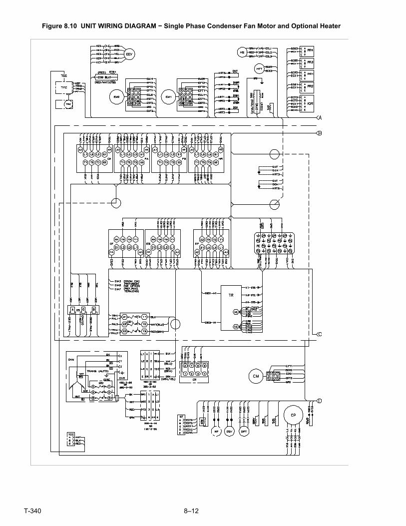
T-340 8–12
Figure 8.10 UNIT WIRING DIAGRAM − Single Phase Condenser Fan Motor and Optional Heater

8–13 T-340
UNIT WIRING DIAGRAM − Single Phase Condenser Fan Motor and Optional Heater
Based on Drawing 62 −66721

T-340 8–14
Figure 8.11 UNIT WIRING DIAGRAM − Configuration With eAutoFresh and Emergency Bypass Options

8–15 T-340
UNIT WIRING DIAGRAM − Configuration With eAutoFresh and Emergency Bypass Options
Based on Drawing 62 −11418 Rev A


Index–1 T-340
INDEX
Numerics
230 Volt Cable 2-3
460 Volt Cable 2-3
A
Abnormal currents 6-6
Abnormal noise or vibrations 6-3
Abnormal pressures 6-3
Abnormal temperatures 6-6
Adding Refrigerant to System (Full Charge) 7-6
Adding Refrigerant to System (Partial Charge) 7-6
Adjust Fresh Air Makeup Vent 5-2
Air-Cooled Condenser Section 3-4
Alarm Configuration (dCF07 - dCF10) 4-20
Alarm Troubleshooting Sequence 4-33
Assemble the Evaporator Fan Assembly 7-16
Automatic Defrost 4-12
Autotransformer 2-2, 7-22
Autotransformer malfunction 6-5
B
Back Panels 2-3
Battery 2-2
Battery Replacement 7-27
C
Cable Restraint 2-3
Check Controller Function Codes 5-7
Checking eAutoFresh Drive System 7-35
Checking High Pressure Switch 7-9
Checking the Auto Slide 7-35
Checking the Controller 7-36
Checking the Drive Module 7-36
Checking the Refrigerant Charge 7-6
Checking the Slide Motor 7-35
Communications Interface Module 2-2, 3-6, 4-22
Communications Interface Module Installation 7-40
Complete Inspection 5-8
Compressor 2-1, 7-7
Compressor High Temp, Low Pressure Protection 4-14
Compressor operating in reverse 6-5
Compressor Section 3-3
Condenser Coil 2-1, 7-10
Condenser Fan and Motor Assembly 7-10
Condenser Fan Override 4-15
Condenser Grille 2-3
Configuration Identification 2-1
Configuration Software (CnF Variables) 4-4
Connect Power 5-1
Connect Remote Monitoring Receptacle 5-7
Connect Water-Cooled Condenser 5-6
Connection To 190/230 VAC Power 5-1
Connection To 380/460 VAC Power 5-1
Control Box 2-1
Control Box Section 3-6
Controller 2-3, 4-3, 7-23
Controller Alarm Indications 4-34
Controller Alarms 4-15
Controller Configuration Variables 4-24
Controller Function Codes 4-25
Controller Pre-Trip Test Codes 4-43
Controller Programming Procedure 7-24
Controller Software 4-3
Controller Troubleshooting 7-23
D
DataBANK™ Card 4-22
DataCORDER 4-16, 5-8
DataCORDER Alarms 4-23
DataCORDER Communications 4-21
DataCORDER Configuration Software 4-17
DataCORDER Operational Software 4-17
DataCORDER Power Up 4-20
DataCORDER Software 4-17
DataLINE 4-22
DataReader 4-21
Defrost 4-11
Defrost Initiation 4-12
Defrost Interval 4-13
Defrost Related Settings 4-13
Dehumidification 2-2
Digital Unloader Valve 7-20
Disassemble the Evaporator Fan Assembly 7-15
Display Module 4-2
E
eAutoFresh 2-3
eAutoFresh Modes of Operation 5-5
eAutoFresh not operating 6-4
eAutoFresh Operation 5-4
eAutoFresh Operational Parameters 5-6
eAutoFresh Pre-Trip Inspection 5-4
eAutoFresh Service 7-35
eAutoFresh Start-Up Procedure 5-5
Economized Operation 3-10

T-340 Index–2
Economizer Expansion Replacement 7-19
Economizer Expansion Valve 7-19
Economizer Solenoid Valve 7-18
Electrical Data 3-8
Electrical Wiring Schematics 8-1
Electronic Expansion Valve 3-10, 7-17
Electronic Expansion Valve malfunction 6-4
Electronic Partlow Temperature Recorder 7-38
Emergency Bypass 2-3
Emergency Bypass Operation 5-10
Evacuation and Dehydration 7-4
Evaporator 2-1
Evaporator Coil & Heater Assembly 7-14
Evaporator Coil Replacement 7-14
Evaporator Fan and Motor Assembly 7-15
Evaporator Fan Operation 2-1, 4-14
Evaporator Heater Replacement 7-14
Evaporator Section 3-2
Evaporator Section Cleaning 7-16
F
Failure Action 4-14
Feature Descriptions 2-1
Filter Drier 7-13
First Aid 1-1
Fresh Air Makeup Vent 3-1
Frozen “Heat” Mode 4-10
Frozen Economy Mode 4-10
Frozen Idle Mode 4-9
Frozen Mode - Temperature Control 4-9
Frozen Mode Cooling - Sequence of Operation 4-10
Frozen Steady State 4-9
G
General Description 3-1
General Protection 4-14
General Safety Notices 1-1
Generic Mode - DataCORDER 4-18
Gutters 2-2
H
Handles 2-2
Handling Modules 7-23
High Pressure Switch 7-9
I
Inspection (Before Loading) 5-1
Installing the Solenoid Valve 7-19
Installing the Solenoid Valve Coil 7-19
Interrogator 2-2
Introduction 2-1
ISO Trip Header 4-23
K
Keypad 4-2
L
Labels 2-3
Logging Interval (dCF03) 4-18
Lower Air (Fresh Air Make Up) 2-3
Lower Fresh Air Makeup Vent 5-3
Lower VPS 7-35
M
Maintenance of Painted Surfaces 7-40
Maintenance Precautions 1-1
Manifold Gauge Set 7-1
Microprocessor malfunction 6-4
Modes of Operation 4-4
N
No evaporator air flow or restricted air flow 6-4
O
Operating Precautions 1-1
Operational Software (Cd Function Codes) 4-4
Option Descriptions 2-1
Optional 5+1 Heater Arrangement 7-14
P
Partlow Recorders 5-8
Perishable Dehumidification 4-6
Perishable Dehumidification - Bulb Mode 4-7
Perishable Economy 4-7
Perishable Heating 4-5
Perishable Idle, Air Circulation 4-5
Perishable Mode - System Pressure Regulation 4-14
Perishable Mode - Trim Heat 4-9
Perishable Mode Cooling - Sequence of Operation 4-7
Perishable Mode Heating - Sequence of Operation 4-8
Perishable Mode Temperature Control 4-5
Perishable Pulldown 4-5
Perishable Steady State 4-5
Physical Inspection 5-7
Plate Set 2-1
Pressure Readout 2-1
Pre-trip Data Recording 4-21
Pre-trip Diagnosis 5-8
Pre-Trip Diagnostics 4-16

Index–3 T-340
Probe Diagnostics 5-10
Probe Disagreement 5-10
Programming Software Versions 5350 and Greater 7-25
Programming Software Versions prior to 5328 7-24
Protection Modes of Operation 4-14
Pump down the unit 7-3
Q
Quest - CCPC 2-2, 4-15
R
Recalibrating the Temp Recorder to Zero 7-40
Refrigerant Charge 7-6
Refrigerant leak checking 7-4
Refrigeration Circuit 3-10
Refrigeration System Data 3-7
Refrigeration Unit - Front Section 3-1
Remote Monitoring 2-2
Removal and Replacement of Compressor 7-7
Removing a Solenoid Valve Coil 7-18
Removing and Installing a Controller 7-27
Removing the Solenoid Valve 7-19
Replacing 7-9
Replacing Electronic Expansion Valve and Screen 7-17
Replacing the Evaporator Fan Assembly 7-15
Replacing the Recorder 7-39
S
Safety and Protective Devices 3-9
Sampling Type (dCF05 & dCF06) 4-20
Sensor Checkout Procedure 7-28
Sensor Configuration (dCF02) 4-17
Sensor Re-Installation 7-32
Sensor Replacement 7-31
Service Connections 7-2
Service Section Layout 7-1
Servicing the eAutoFresh Air Filter 7-35
Servicing the eAutoFresh Drive System 7-37
Specific Hazard Statements 1-1
Standard Mode 4-17
Standard Operation 3-10
Start Temperature Recorder 5-8
Start up - Compressor Bump Start 4-5
Start up - Compressor Phase Sequence 4-5
Starting and Stopping Instructions 5-7
Starting the Unit 5-7
Start-up Inspection 5-7
Stopping the Unit 5-7
T
Temperature Control Microprocessor System 4-1
Temperature Readout 2-1
Temperature Recorder 2-2
Temperature Sensor Service 7-28
Thermistor Format (dCF04) 4-18
Thermometer Port 2-2
To Display Alarm Codes 4-15
To start a Pre-trip test 5-9
U
Unit runs but has insufficient cooling 6-2
Unit will not defrost properly 6-2
Unit will not heat or has insufficient heating 6-2
Unit will not terminate heating 6-2
Upper Air (Fresh Air Make Up) 2-3
Upper Fresh Air Makeup Vent 5-2
Upper VPS 7-34
USDA 2-2
USDA Cold Treatment 4-22
USDA Cold Treatment Procedure 4-22
V
Valve Override Controls 7-21
Vent Position Sensor 5-4
Vent Position Sensor (VPS) 7-34
W
Water Cooling 2-2
Water-Cooled Condenser Cleaning 7-10
Water-Cooled Condenser Section 3-5
Water-Cooled Condenser w/Condenser Fan Switch 5-6
Water-Cooled Condenser w/Water Pressure Switch 5-6
Water-Cooled Condenser/Pressure Switch malfnct. 6-5
When an Alarm Occurs 4-15


A part of UTC Building & Industrial Systems, a business unit of UnitedTechnologies Corporation. Stock symbol UTX.
Carrier Transicold Division,Carrier CorporationP.O. Box 4805Syracuse, NY 13221 USA
www.carrier.transicold.com