Embed Size (px)
Citation preview

1
OPERATIONS MANUAL
FOR VEPRTM II RIFLES
ROBINSON ARMAMENT CO. PO BOX 16776 SALT LAKE CITY, UT 84116 url: www.robarm.com

2
WARNING!!!
READ THIS OPERATION MANUAL CAREFULLY AND RECEIVE FIREARMS SAFETY TRAINING FROM A COMPETENT INSTRUCTOR BEFORE HAN-DLING OR OPERATING THIS FIREARM. THIS OP-ERATION MANUAL CONTAINS IMPORTANT WARNINGS WHICH MUST BE UNDERSTOOD AND FOLLOWED BY ANYONE HANDLING OR OPERAT-ING THIS FIREARM. IMPROPER HANDLING OR OPERATING OF ANY FIREARM MAY RESULT IN SERIOUS BODILY IN-JURY, DEATH, OR DESTRUCTION OF PROPERTY. NEITHER THE MANUFACTURER, IMPORTER, NOR THE DISTRIBUTOR SHALL BE LIABLE FOR ANY INJURY TO PERSONS OR ANY DAMAGE TO PROP-ERTY RESULTING FROM THE USE OF THIS FIRE-ARM. THIS OPERATION MANUAL SHOULD ACCOMPANY THE FIREARM AT ALL TIMES AND SHOULD BE TRANSFERRED WITH POSSESSION OF THE FIRE-ARM TO ANY SUBSEQUENT OWNER OR OPERA-TOR. ALWAYS REMEMBER TO KEEP FIREARMS AND AMMUNITION LOCKED UP AND OUT OF THE REACH OF CHILDREN AND OTHER UNAUTHOR-IZED INDIVIDUALS. SAFETY IS YOUR RESPONSI-BILITY!!!
Copyright 2000 Robinson Armament Co. All Rights Reserved

3
TABLE OF CONTENTS SECTON I FIREARM SAFETY RULES 4 SECTION II TERMINOLOGY 5 SECTION III DESCRIPTION OF THE VEPR’S ACTION 6 SECTION IV LOADING THE VEPR 9 SECTION V AIMING THE VEPR 12 SECTION VI FIRING THE VEPR 13 SECTION VII UNLOADING THE VEPR 15 SECTION VIII DISASSEMBLY PROCEDURES 17 SECTION IX ASSEMBLY PROCEDURES 20 SECTION X CLEANING AND LUBRICATION 22 SECTION XI ATTACHING THE SCOPE MOUNT 23 SECTION XII CHILD SAFETY LOCK 24 SECTION XIII MODIFICATIONS 25 SECTION XIV SPECIFICATIONS 26
4
SECTION I - FIREARM SAFETY RULES WARNING!!! THESE SAFETY RULES ARE OF A GENERAL NATURE ONLY. THEY ARE NOT IN-TENDED TO BE EXHAUSTIVE NOR ARE THEY IN-TENDED TO BE A SUBSTITUTE FOR PROPER FIRE-ARMS TRAINING FROM A COMPETENT FIREARMS INSTRUCTOR. 1. Always keep the firearm pointed in a safe direction. Fire-
arms must be treated as if always loaded and always firing a steady stream of bullets. Do not point the muzzle of the firearm at any thing you do not intend to kill or destroy.
2. Never place your finger on the trigger until you are ready to
fire. Before placing your finger on the trigger, make sure that you have first assumed a stable shooting position and have your intended target clearly within your sights.
3. Clearly identify your target and backstop before you pull
the trigger. Rifle cartridges are very powerful and have a le-thal range of many miles. They can often penetrate hard objects such as walls and metal. Before you pull the trigger, it is vital that you clearly identify your target and have a backstop behind the target capable of stopping rifle bullets. Do not fire at hard objects or at water which can cause bullets to ricochet and hit unintended objects.
4. Always wear adequate eye and hearing protection while
shooting. Firearms, upon discharge, are extremely loud, and violently eject spent cases, hot gasses and particles. Operators and bystanders must wear adequate eye and hearing protection at all times when a firearm is being discharged to prevent per-manent vision and hearing loss.
5. Always store your firearms unloaded, locked up, and out of
the reach of children and other unauthorized individuals. Be sure to keep your firearms locked in a secure place when not in use. It is your responsibility to make sure that children and other unauthorized individuals do not have access to your fire-arms.
5
SEC
TIO
N II
– T
ER
MIN
OL
OG
Y
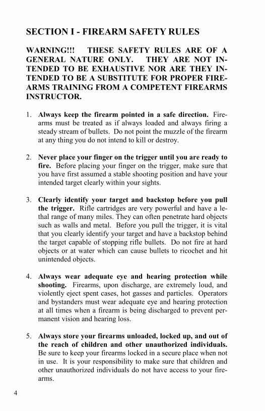
TA
KE
TIM
E T
O T
HO
RO
UG
HL
Y F
AM
ILIA
RIZ
E Y
OU
RSE
LF
WIT
H T
HE
TE
RM
S IN
TH
IS S
EC
TIO
N D
E-
SCR
IBIN
G T
HE
FE
AT
UR
ES
AN
D C
OM
PON
EN
TS
OF
TH
E V
EPR
AS
TH
EY
WIL
L B
E R
EFE
RR
ED
TO
T
HR
OU
GH
OU
T T
HIS
MA
NU
AL
.
6
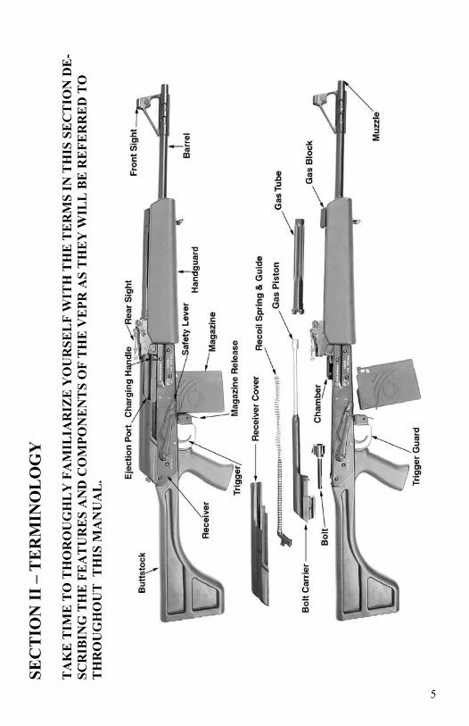
SECTION III - DESCRIPTION OF THE VEPR’S ACTION The VEPR is a gas operated semiautomatic sporting rifle. The VEPR’s action is based on that of the Automat Kalash-nikov designed by Mikhail Kalashnikov in the former Soviet Union shortly after WWII. The operating cycle of this semi-automatic action is briefly described below. To begin the description of the operating cycle, it is assumed that the following operations have been performed: A loaded magazine has been inserted into the firearm. And a cartridge has been manually cycled into the chamber. The hammer is held in the cocked position by the trigger (See Fig.1).
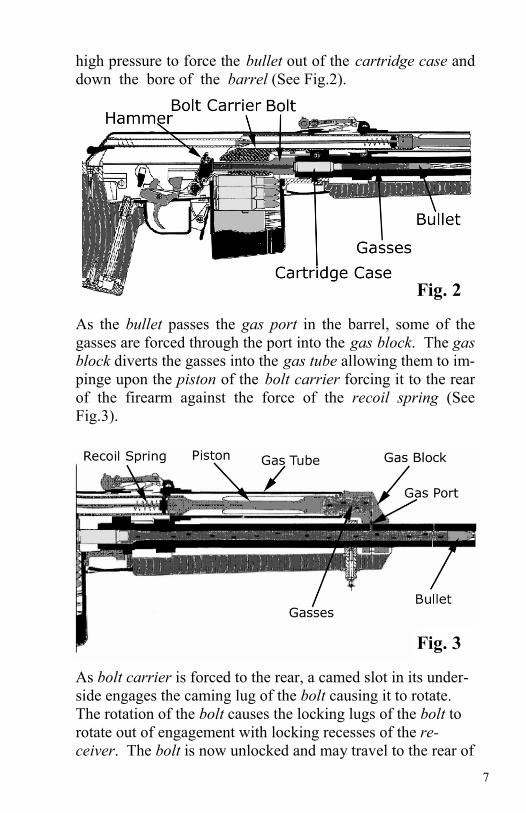
As the trigger is pulled, the hammer is released from engage-ment with the trigger. The hammer, under the force of its spring, rotates forward and upward into contact with the firing pin which is contained in the bolt which is itself contained in the bolt carrier (See Fig. 2). As the hammer strikes the end of the firing pin, the tip of the firing pin is forced to strike the primer of the cartridge causing it to ignite. The ignited primer causes the powder within the cartridge case to burn. The burning powder creates gasses that expand under very
Fig. 1
7
high pressure to force the bullet out of the cartridge case and down the bore of the barrel (See Fig.2).
As the bullet passes the gas port in the barrel, some of the gasses are forced through the port into the gas block. The gas block diverts the gasses into the gas tube allowing them to im-pinge upon the piston of the bolt carrier forcing it to the rear of the firearm against the force of the recoil spring (See Fig.3).
Fig. 2
Fig. 3
As bolt carrier is forced to the rear, a camed slot in its under-side engages the caming lug of the bolt causing it to rotate. The rotation of the bolt causes the locking lugs of the bolt to rotate out of engagement with locking recesses of the re-ceiver. The bolt is now unlocked and may travel to the rear of

8
the receiver with the bolt carrier (See Fig 4). As the bolt carrier and bolt travel further to the rear of the firearm, the extractor which is engaging the rim of the cartridge case pulls the empty cartridge from the chamber. As the bolt carrying the empty cartridge passes the ejector, the spent case is forced out of the grip of the extractor and is ejected from the right side of the firearm. During the bolt car-rier’s rearward movement, the hammer is rotated against the force of its spring into engagement with the trigger (See Fig.4).
As the bolt carrier with its bolt reaches the rear limit of its travel, the compressed recoil spring forces the bolt carrier and bolt forward. As the bolt passes the rear of the maga-zine, a new cartridge is forced from the magazine into the chamber. Simultaneously, the extractor is forced over the rim of the new cartridge case and the lugs of the bolt are rotated into engagement with the recesses in the firearm’s receiver. The bolt carrier continues forward until it reaches its forward limit. One complete cycle has now been completed and the firearm is ready to be fired again by pulling the trigger.
Fig. 4
9
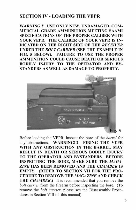
SECTION IV - LOADING THE VEPR WARNING!!! USE ONLY NEW, UNDAMAGED, COM-MERCIAL GRADE AMMUNITION MEETING SAAMI SPECIFICATIONS OF THE PROPER CALIBER WITH YOUR VEPR. THE CALIBER OF YOUR VEPR IS IN-DICATED ON THE RIGHT SIDE OF THE RECEIVER UNDER THE BOLT CARRIER (SEE THE EXAMPLE IN FIG. 5 BELOW). FAILURE TO USE THE PROPER AMMUNITION COULD CAUSE DEATH OR SERIOUS BODILY INJURY TO THE OPERATOR AND BY-STANDERS AS WELL AS DAMAGE TO PROPERTY.
Before loading the VEPR, inspect the bore of the barrel for any obstructions. WARNING!!! FIRING THE VEPR WITH ANY OBSTRUCTION IN THE BARREL MAY RESULT IN DEATH OR SERIOUS BODILY INJURY TO THE OPERATOR AND BYSTANDERS. BEFORE INSPECTING THE BORE, MAKE SURE THE MAGA-ZINE HAS BEEN REMOVED AND THE CHAMBER IS EMPTY. (REFER TO SECTION VII FOR THE PRO-CEDURE TO REMOVE THE MAGAZINE AND CHECK THE CHAMBER.) It is recommended that you remove the bolt carrier from the firearm before inspecting the bore. (To remove the bolt carrier, please see the Disassembly Proce-dures in Section VIII of this manual).
Fig. 5
10
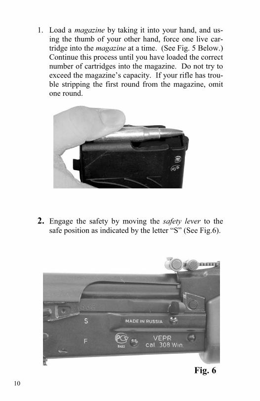
1. Load a magazine by taking it into your hand, and us-ing the thumb of your other hand, force one live car-tridge into the magazine at a time. (See Fig. 5 Below.) Continue this process until you have loaded the correct number of cartridges into the magazine. Do not try to exceed the magazine’s capacity. If your rifle has trou-ble stripping the first round from the magazine, omit one round.
2. Engage the safety by moving the safety lever to the
safe position as indicated by the letter “S” (See Fig.6).
Fig. 6
11
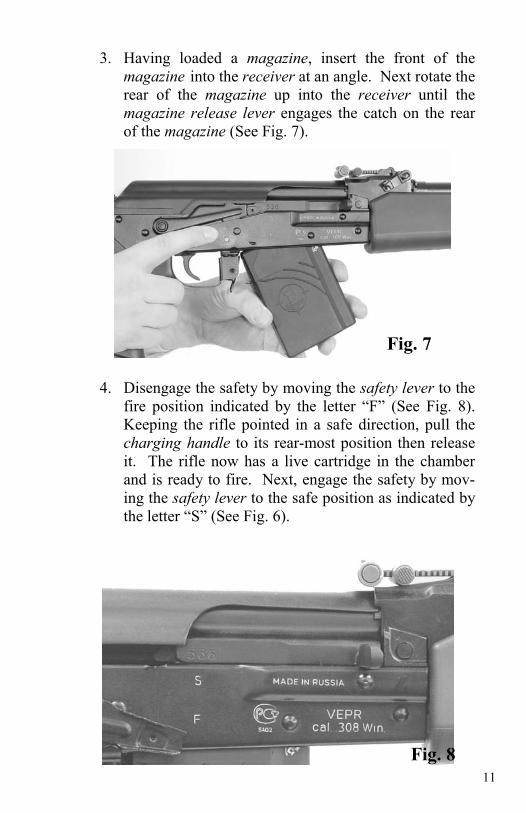
3. Having loaded a magazine, insert the front of the magazine into the receiver at an angle. Next rotate the rear of the magazine up into the receiver until the magazine release lever engages the catch on the rear of the magazine (See Fig. 7).
4. Disengage the safety by moving the safety lever to the fire position indicated by the letter “F” (See Fig. 8). Keeping the rifle pointed in a safe direction, pull the charging handle to its rear-most position then release it. The rifle now has a live cartridge in the chamber and is ready to fire. Next, engage the safety by mov-ing the safety lever to the safe position as indicated by the letter “S” (See Fig. 6).
Fig. 7
Fig. 8
12
SECTION V - AIMING THE VEPR
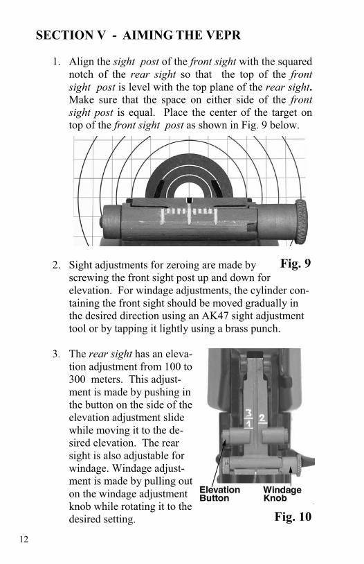
1. Align the sight post of the front sight with the squared notch of the rear sight so that the top of the front sight post is level with the top plane of the rear sight. Make sure that the space on either side of the front sight post is equal. Place the center of the target on top of the front sight post as shown in Fig. 9 below.
2. Sight adjustments for zeroing are made by
screwing the front sight post up and down for elevation. For windage adjustments, the cylinder con-taining the front sight should be moved gradually in the desired direction using an AK47 sight adjustment tool or by tapping it lightly using a brass punch.
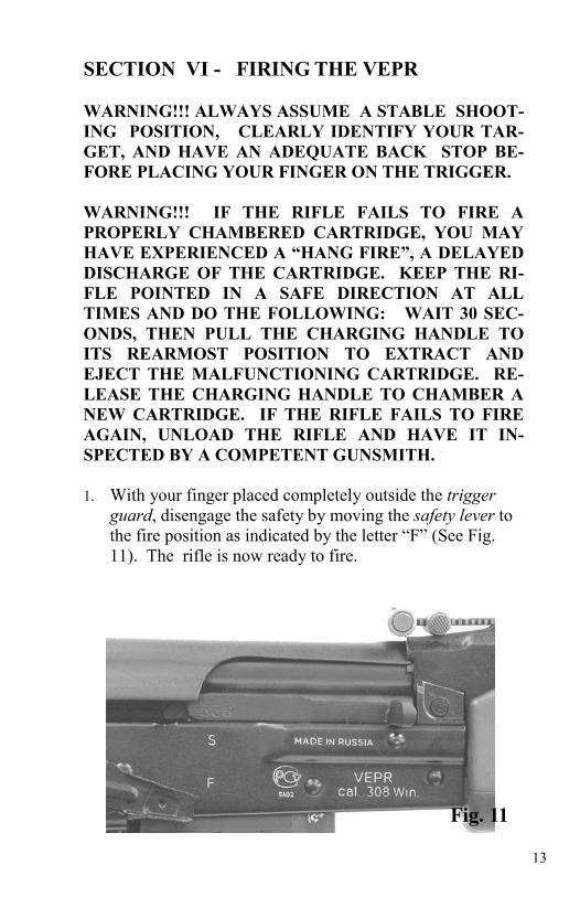
3. The rear sight has an eleva-
tion adjustment from 100 to 300 meters. This adjust-ment is made by pushing in the button on the side of the elevation adjustment slide while moving it to the de-sired elevation. The rear sight is also adjustable for windage. Windage adjust-ment is made by pulling out on the windage adjustment knob while rotating it to the desired setting.
Fig. 9
Fig. 10
13
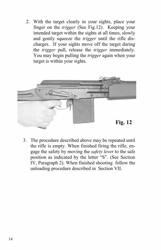
SECTION VI - FIRING THE VEPR WARNING!!! ALWAYS ASSUME A STABLE SHOOT-ING POSITION, CLEARLY IDENTIFY YOUR TAR-GET, AND HAVE AN ADEQUATE BACK STOP BE-FORE PLACING YOUR FINGER ON THE TRIGGER. WARNING!!! IF THE RIFLE FAILS TO FIRE A PROPERLY CHAMBERED CARTRIDGE, YOU MAY HAVE EXPERIENCED A “HANG FIRE”, A DELAYED DISCHARGE OF THE CARTRIDGE. KEEP THE RI-FLE POINTED IN A SAFE DIRECTION AT ALL TIMES AND DO THE FOLLOWING: WAIT 30 SEC-ONDS, THEN PULL THE CHARGING HANDLE TO ITS REARMOST POSITION TO EXTRACT AND EJECT THE MALFUNCTIONING CARTRIDGE. RE-LEASE THE CHARGING HANDLE TO CHAMBER A NEW CARTRIDGE. IF THE RIFLE FAILS TO FIRE AGAIN, UNLOAD THE RIFLE AND HAVE IT IN-SPECTED BY A COMPETENT GUNSMITH. 1. With your finger placed completely outside the trigger
guard, disengage the safety by moving the safety lever to the fire position as indicated by the letter “F” (See Fig. 11). The rifle is now ready to fire.
Fig. 11
14
2. With the target clearly in your sights, place your finger on the trigger (See Fig.12). Keeping your intended target within the sights at all times, slowly and gently squeeze the trigger until the rifle dis-charges. If your sights move off the target during the trigger pull, release the trigger immediately. You may begin pulling the trigger again when your target is within your sights.
3. The procedure described above may be repeated until
the rifle is empty. When finished firing the rifle, en-gage the safety by moving the safety lever to the safe position as indicated by the letter “S”. (See Section IV, Paragraph 2). When finished shooting follow the unloading procedure described in Section VII.
Fig. 12
15
SECTION VII – UNLOADING THE VEPR WARNING!!! THE RIFLE MAY STILL BE LOADED EVEN THOUGH THE MAGAZINE IS REMOVED. THERE MAY STILL BE A ROUND IN THE CHAMBER WHICH COULD BE DISCHARGED IF THE TRIGGER IS PULLED.
1. Remove the magazine from the rifle by depressing the magazine release lever with your thumb (See Fig.13) while simultaneously rotating the rear of the magazine down and away from the rifle, completely removing it from the receiver (See Fig.14).
Fig. 13
Fig. 14
16
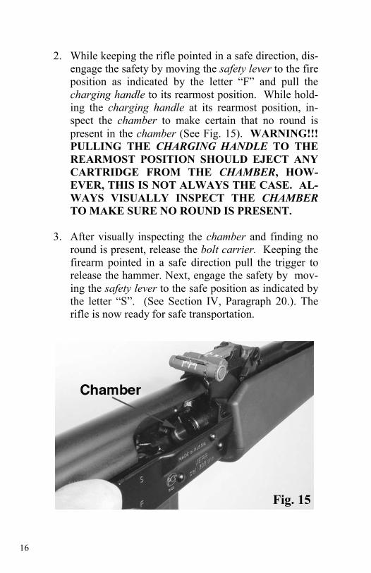
2. While keeping the rifle pointed in a safe direction, dis-
engage the safety by moving the safety lever to the fire position as indicated by the letter “F” and pull the charging handle to its rearmost position. While hold-ing the charging handle at its rearmost position, in-spect the chamber to make certain that no round is present in the chamber (See Fig. 15). WARNING!!!PULLING THE CHARGING HANDLE TO THE REARMOST POSITION SHOULD EJECT ANY CARTRIDGE FROM THE CHAMBER, HOW-EVER, THIS IS NOT ALWAYS THE CASE. AL-WAYS VISUALLY INSPECT THE CHAMBER TO MAKE SURE NO ROUND IS PRESENT.
3. After visually inspecting the chamber and finding no
round is present, release the bolt carrier. Keeping the firearm pointed in a safe direction pull the trigger to release the hammer. Next, engage the safety by mov-ing the safety lever to the safe position as indicated by the letter “S”. (See Section IV, Paragraph 20.). The rifle is now ready for safe transportation.
Fig. 15
17
SECTION VIII - DISASSEMBLY PROCE-DURES WARNING!!! ADEQUATE EYE PROTECTION SHOULD ALWAYS BE WORN WHILE DISASSEM-BLING ANY FIREARM AS SPRING LOADED PARTS MAY JUMP FROM THE FIREARM AND MAY CAUSE PERMANENT VISION LOSS OR OTHER SERIOUS DAMAGE. 1. Remove the magazine from the rifle and make sure no
round is present in the chamber as described in Section VII – Unloading the VEPR.
2. Move the safety lever to the safe position (See Section
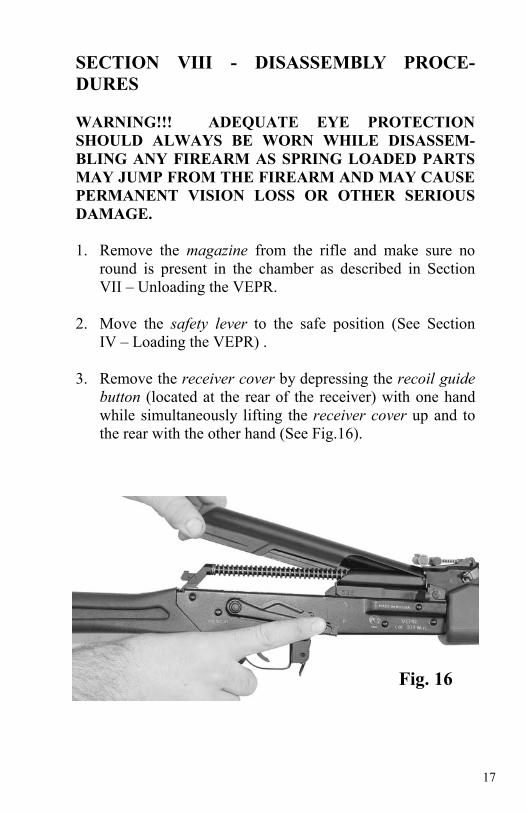
IV – Loading the VEPR) . 3. Remove the receiver cover by depressing the recoil guide
button (located at the rear of the receiver) with one hand while simultaneously lifting the receiver cover up and to the rear with the other hand (See Fig.16).
Fig. 16
18
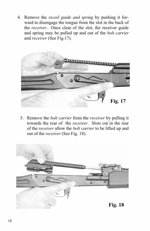
4. Remove the recoil guide and spring by pushing it for-ward to disengage the tongue from the slot in the back of the receiver. Once clear of the slot, the receiver guide and spring may be pulled up and out of the bolt carrier and receiver (See Fig.17).
5. Remove the bolt carrier from the receiver by pulling it
towards the rear of the receiver. Slots cut in the rear of the receiver allow the bolt carrier to be lifted up and out of the receiver (See Fig. 18).
Fig. 17
Fig. 18
19
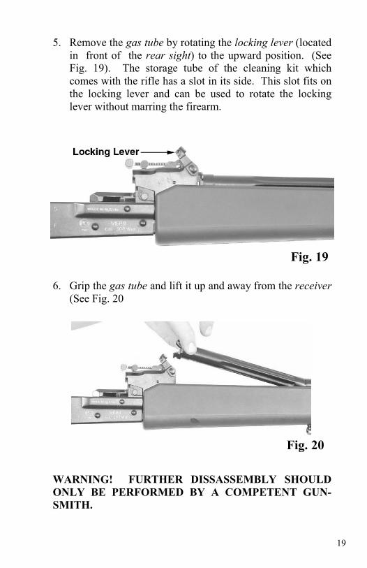
5. Remove the gas tube by rotating the locking lever (located in front of the rear sight) to the upward position. (See Fig. 19). The storage tube of the cleaning kit which comes with the rifle has a slot in its side. This slot fits on the locking lever and can be used to rotate the locking lever without marring the firearm.
6. Grip the gas tube and lift it up and away from the receiver (See Fig. 20
WARNING! FURTHER DISSASSEMBLY SHOULD ONLY BE PERFORMED BY A COMPETENT GUN-SMITH.
Fig. 19
Fig. 20
20
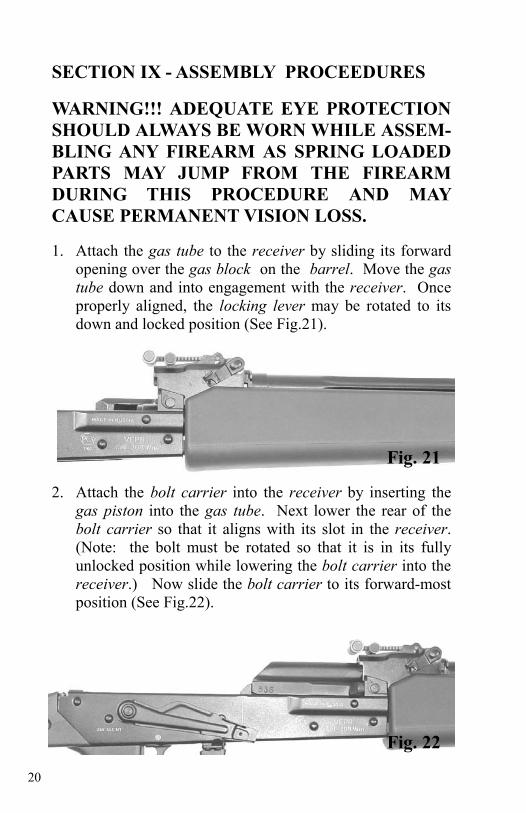
SECTION IX - ASSEMBLY PROCEEDURES WARNING!!! ADEQUATE EYE PROTECTION SHOULD ALWAYS BE WORN WHILE ASSEM-BLING ANY FIREARM AS SPRING LOADED PARTS MAY JUMP FROM THE FIREARM DURING THIS PROCEDURE AND MAY CAUSE PERMANENT VISION LOSS. 1. Attach the gas tube to the receiver by sliding its forward
opening over the gas block on the barrel. Move the gas tube down and into engagement with the receiver. Once properly aligned, the locking lever may be rotated to its down and locked position (See Fig.21).
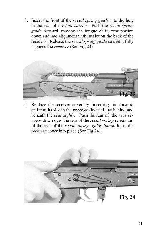
2. Attach the bolt carrier into the receiver by inserting the gas piston into the gas tube. Next lower the rear of the bolt carrier so that it aligns with its slot in the receiver. (Note: the bolt must be rotated so that it is in its fully unlocked position while lowering the bolt carrier into the receiver.) Now slide the bolt carrier to its forward-most position (See Fig.22).
Fig. 21
Fig. 22
21
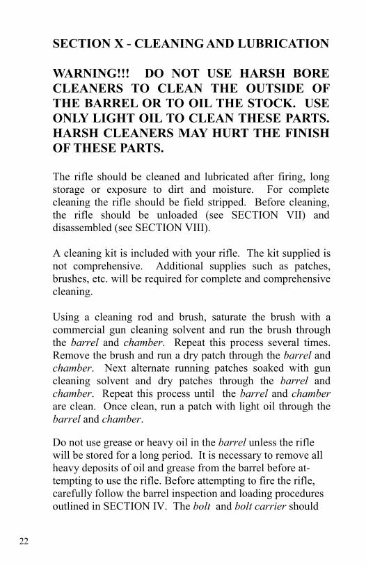
3. Insert the front of the recoil spring guide into the hole in the rear of the bolt carrier. Push the recoil spring guide forward, moving the tongue of its rear portion down and into alignment with its slot on the back of the receiver. Release the recoil spring guide so that it fully engages the receiver (See Fig.23)
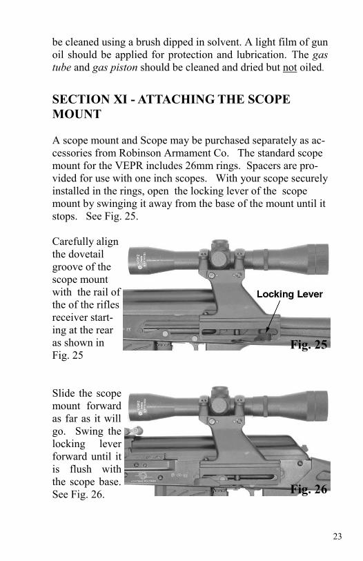
4. Replace the receiver cover by inserting its forward end into its slot in the receiver (located just behind and beneath the rear sight). Push the rear of the receiver cover down over the rear of the recoil spring guide un-til the rear of the recoil spring guide button locks the receiver cover into place (See Fig.24).
Fig. 23
Fig. 24
22
SECTION X - CLEANING AND LUBRICATION WARNING!!! DO NOT USE HARSH BORE CLEANERS TO CLEAN THE OUTSIDE OF THE BARREL OR TO OIL THE STOCK. USE ONLY LIGHT OIL TO CLEAN THESE PARTS. HARSH CLEANERS MAY HURT THE FINISH OF THESE PARTS. The rifle should be cleaned and lubricated after firing, long storage or exposure to dirt and moisture. For complete cleaning the rifle should be field stripped. Before cleaning, the rifle should be unloaded (see SECTION VII) and disassembled (see SECTION VIII). A cleaning kit is included with your rifle. The kit supplied is not comprehensive. Additional supplies such as patches, brushes, etc. will be required for complete and comprehensive cleaning. Using a cleaning rod and brush, saturate the brush with a commercial gun cleaning solvent and run the brush through the barrel and chamber. Repeat this process several times. Remove the brush and run a dry patch through the barrel and chamber. Next alternate running patches soaked with gun cleaning solvent and dry patches through the barrel and chamber. Repeat this process until the barrel and chamber are clean. Once clean, run a patch with light oil through the barrel and chamber. Do not use grease or heavy oil in the barrel unless the rifle will be stored for a long period. It is necessary to remove all heavy deposits of oil and grease from the barrel before at-tempting to use the rifle. Before attempting to fire the rifle, carefully follow the barrel inspection and loading procedures outlined in SECTION IV. The bolt and bolt carrier should
23
SECTION XI - ATTACHING THE SCOPE MOUNT A scope mount and Scope may be purchased separately as ac-cessories from Robinson Armament Co. The standard scope mount for the VEPR includes 26mm rings. Spacers are pro-vided for use with one inch scopes. With your scope securely installed in the rings, open the locking lever of the scope mount by swinging it away from the base of the mount until it stops. See Fig. 25. Carefully align the dovetail groove of the scope mount with the rail of the of the rifles receiver start-ing at the rear as shown in Fig. 25 Slide the scope mount forward as far as it will go. Swing the locking lever forward until it is flush with the scope base. See Fig. 26.
be cleaned using a brush dipped in solvent. A light film of gun oil should be applied for protection and lubrication. The gas tube and gas piston should be cleaned and dried but not oiled.
Fig. 25
Fig. 26
24
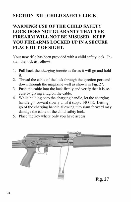
SECTION XII - CHILD SAFETY LOCK WARNING! USE OF THE CHILD SAFETY LOCK DOES NOT GUARANTY THAT THE FIREARM WILL NOT BE MISUSED. KEEP YOU FIREARMS LOCKED UP IN A SECURE PLACE OUT OF SIGHT. Your new rifle has been provided with a child safety lock. In-stall the lock as follows: 1. Pull back the charging handle as far as it will go and hold
it. 2. Thread the cable of the lock through the ejection port and
down through the magazine well as shown in Fig. 27. 3. Push the cable into the lock firmly and verify that it is se-
cure by giving a tug on the cable. 4. While holding onto the charging handle, let the charging
handle go forward slowly until it stops. NOTE: Letting go of the charging handle allowing it to slam forward may damage the cable of the child safety lock.
5. Place the key where only you have access.
Fig. 27
25
SECTION XIII - MODIFICATIONS WARNING!!! THE MODIFICATION OF ANY PART OF THE FIREARM MAY RESULT IN DEATH, SERIOUS BODILY INJURY, AND DAMAGE TO PROPERTY. THIS FIREARM, AS CONFIGURED (WITH A US MADE TRIGGER, DISCONNECT, BUTTSTOCK, PISTOL GRIP, AND HAND-GUARD) MEETS CURRENT FEDERAL LAW. THE ADDITION, MODIFICATION, OR SUB-STITUTION OF ANY PART OR PARTS OF THE FIREARM MAY BE ILLEGAL. CONSULT YOUR OWN LEGAL COUNSEL BEFORE MODIFYING YOUR RIFLE.
26
VEPRTM II .308 RIFLE SPECIFICATIONS
SECTION XIV - SPECIFICATIONS GENERAL SPECIFICATIONS
Semiauto Action Kalashnikov, Gas Operated, Rotating Bolt
Receiver RPK Type with Extra Reinforcement
Front Sight Post, Adjustable for Windage & Ele-vation
Rear Sight Notch, Adjustable for Windage & Ele-vation
Safety Flag Type
Furniture Glass Reinforced Composite
Scope Mounting Side Rail for Quick Attach Scope Mounting.
Caliber .308 Win. (7.62x51mm)
Barrel 20.5” (520mm) Long, Chome-Lined, Hammer-Forged
Overall length 39.75” (1010mm)
Weight 9.0 lbs. (4500 grams)
Feeding Devices 5 and 10 Round VEPR Magazines

27
VEPRTM II & K .223 RIFLE SPECIFICA-TIONS
Caliber .223 Rem. (5.56x45mm)
Barrel 20.5” or 16.5”(Long, Chome-Lined, Hammer-Forged, 1 in 9”
Overall length 39.75” or 35.75” Weight 9.2 lbs. or 8.8 lbs. Feeding Devices 30 Round .223 Magazine, Proprie-
tary.
VEPRTM II & K 7.62x39mm RIFLE SPECIFI-CATIONS
Caliber 7.62x39mm Russian
Barrel 20.5” or 16.5” Long, Chome-Lined, Hammer-Forged
Overall length 39.75” or 35.75”
Weight 8.9 lbs. or 8.2 lbs.
Feeding Devices 30 Round AK47 Magazines and Drums
VEPRTM II or K 5.45x39mm RIFLE SPECIFI-CATIONS
Caliber 5.45x39mm Russian
Barrel 20.5” or 16.5” Long, Chome-Lined, Hammer-Forged
Overall length 39.75” or 35.75
Weight 9.2 lbs. or 8.8 lbs.
Feeding Devices 30 Round AK74 Magazines

28
![Sniper Rifles - pmulcahy.compmulcahy.com/PDFs/small_arms/sniper_rifles.pdf · Sniper Rifles sniper_rifles_2.html[12/13/2017 10:15:29 AM] SNIPER RIFLES Armenian Sniper Rifles Australian](https://img.pdfslide.net/doc/110x75/5b38733d7f8b9a4a728d1f41/sniper-rifles-sniper-rifles-sniperrifles2html12132017-101529-am-sniper.jpg)