Embed Size (px)
Citation preview
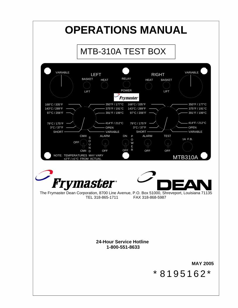
OPERATIONS MANUAL
VARIABLE LEFTHEATBASKET
LIFT
RIGHTBASKETHEAT
LIFT
VARIABLE
SHORT3°C / 37°F
79°C / 175°F
97°C / 206°F 143°C / 289°F 168°C / 335°F
VARIABLEOPEN414°F / 212°C
391°F / 199°C 375°F / 191°C 350°F / 177°C
SHORT3°C / 37°F
79°C / 175°F
97°C / 206°F 143°C / 289°F 168°C / 335°F
VARIABLEOPEN414°F / 212°C
391°F / 199°C 375°F / 191°C 350°F / 177°C
MTB310ANOTE: TEMPERATURES MAY VARY ±2°F / ±1°C FROM ACTUAL.
FUSE
CMIII
CMII
OFFSOUND OFF
ALARM
OFF
ALARM
OFF
TESTON
OFF
POWER
1A F.B.
RELAY
POWER
The Frymaster Dean Corporation, 8700 Line Avenue, P.O. Box 51000, Shreveport, Louisiana 71135
TEL 318-865-1711 FAX 318-868-5987
24-Hour Service Hotline 1-800-551-8633
MAY 2005 *8195162*
MTB-310A TEST BOX
2
TABLE OF CONTENTS
Page #
INTRODUCTION 3
PARTS ORDERING 3
PARTS LIST 4
CONTROL PANEL DIAGRAM 5
COMPUTER MAGIC III.5 / DEAN Compu-Fry TEST PROCEDURE 6
SOLID STATE CONTROLLER TEST PROCEDURE 8
M2000 TEST PROCEDURE 9
DIGITAL CONTROLLER TEST PROCEDURE 12
ELECTRONIC TIMER TEST PROCEDURE 13
CM4-S TEST PROCEDURE 14
KFC-1 / SMS TEST PROCEDURE 15
3
INTRODUCTION The MTB-310A Test Box is a tester designed to test most Frymaster cooking computers and controllers for correct operating and controlling functions.
PARTS ORDERING Parts orders must be placed directly with your local Factory Authorized Parts Distributor. If you do not have a Factory Authorized Service Center list, please contact Frymaster Service Department at 1-800-551-8633 or 1-318-865-1711. To speed up your order, the following information is required: Model Number: __________________ Part Number: __________________ Quantity Required: __________________ PARTS ORDERING/SERVICE INFORMATION CANADA – Garland Commercial Ranges, Ltd., 1177 Kamato Road, Mississauga, Ontario L4W 1X4. NOTE: RETAIN AND STORE THIS MANUAL IN A SAFE PLACE FOR FUTURE USE. ADDITIONAL COPIES MAY BE OBTAINED FROM YOUR FACTORY AUTHORIZED SERVICE CENTER.
4
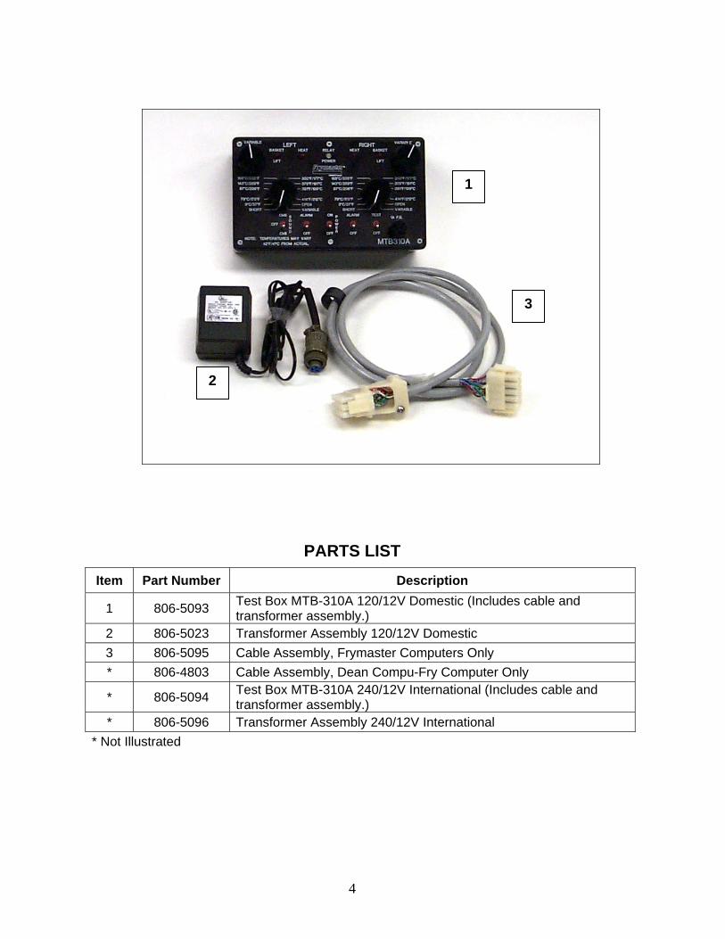
PARTS LIST Item Part Number Description
1 806-5093 Test Box MTB-310A 120/12V Domestic (Includes cable and transformer assembly.)
2 806-5023 Transformer Assembly 120/12V Domestic 3 806-5095 Cable Assembly, Frymaster Computers Only * 806-4803 Cable Assembly, Dean Compu-Fry Computer Only
* 806-5094 Test Box MTB-310A 240/12V International (Includes cable and transformer assembly.)
* 806-5096 Transformer Assembly 240/12V International * Not Illustrated
1
2
3
5
VARIABLE LEFTHEAT
21
BASKET
LIFT
RIGHTBASKET
54
HEAT
LIFT
VARIABLE
SHORT
6
3°C / 37°F 79°C / 175°F
97°C / 206°F 143°C / 289°F 168°C / 335°F
VARIABLEOPEN414°F / 212°C
391°F / 199°C 375°F / 191°C 350°F / 177°C
SHORT
7
3°C / 37°F 79°C / 175°F
97°C / 206°F 143°C / 289°F 168°C / 335°F
VARIABLEOPEN414°F / 212°C
391°F / 199°C 375°F / 191°C 350°F / 177°C
MTB310ANOTE: TEMPERATURES MAY VARY ±2°F / ±1°C FROM ACTUAL.
FUSE
CMIII
CMII
OFF
8 SOUND OFF
ALARM9
OFF
ALARM11
OFF
TEST12ON
OFF
10 POWER
1A F.B.
3
RELAY
POWER
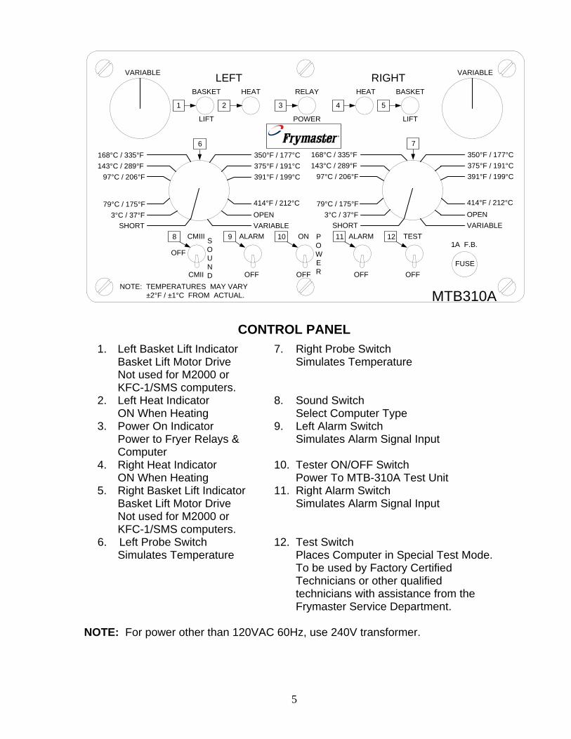
CONTROL PANEL
1. Left Basket Lift Indicator Basket Lift Motor Drive Not used for M2000 or KFC-1/SMS computers.
7. Right Probe Switch Simulates Temperature
2. Left Heat Indicator ON When Heating
8. Sound Switch Select Computer Type
3. Power On Indicator Power to Fryer Relays & Computer
9. Left Alarm Switch Simulates Alarm Signal Input
4. Right Heat Indicator ON When Heating
10. Tester ON/OFF Switch Power To MTB-310A Test Unit
5. Right Basket Lift Indicator Basket Lift Motor Drive Not used for M2000 or KFC-1/SMS computers.
11. Right Alarm Switch Simulates Alarm Signal Input
6. Left Probe Switch Simulates Temperature
12. Test Switch Places Computer in Special Test Mode. To be used by Factory Certified Technicians or other qualified technicians with assistance from the Frymaster Service Department.
NOTE: For power other than 120VAC 60Hz, use 240V transformer.
6
COMPUTER MAGIC III.5 / DEAN Compu-Fry* TEST PROCEDURE
A. INITIAL TEST SET-UP 1. Set-up MTB-310A as follows:
(a) Set ALARM switches (9 & 11) to OFF. (b) Set PROBE switches (6 & 7) to 97°C/206°F. If using a Solid-State or
Digital Controller, set to 79°C/175°F. (c) Set POWER switch (10) to OFF. (d) Set SOUND switch (8) as required for each computer type. (e) Connect 120/24V transformer to 120VAC outlet or 240/24V
transformer to 240VAC outlet. 2. Set computer/controller up as follows:
(a) Set POWER switches to OFF. (b) Set MELT switches to OFF. (Solid state controller only) (c) Connect MTB-310A 15-pin connector to rear of computer or
controller. 3. Set MTB-310A POWER switch (10) to ON
(a) If using a CMIII.5, CM4-S or KFC1/SMS computer, program the set point to 375°F/191°C. If using an M2000 computer, use programming instructions in fryer service manual to program “FR FRIES” set point temperature to 168°C/335°F. If using a Digital Controller or an Electronic Timer/Basket Lift, program the setpoint to 350°F/177°C.
B. TEST POWER TO FRYER INTERFACE BOARD 1. Press Computer/Controller ON/OFF switch to ON. 2. RELAY POWER indicator (3) should illuminate. NOTE: If testing a split vat computer or dual vat controller, complete previous step utilizing both computer/controller power switches (one ON at a time unless an M2000 computer or Electronic Timer/Basket Lift is being tested. Both sides of these computers can be tested at the same time.).
C. TEST MELT-CYCLE FUNCTION 1. Press Computer/Controller ON/OFF switch to ON. 2. Set MTB-310A PROBE switches (6 & 7) to 79°C/175°F.
(a) RELAY POWER indicator (3) will illuminate. (b) HEAT indicators (2 & 4) should cycle on and off with the computer
heating indicator (decimal point on computers and digital controllers). “CYCL”, “LOW TEMP” or “LOW” will be displayed on the computers depending on the model.
3. Set MTB-310A PROBE switches (6 & 7) to 97°C/206°F. (a) HEAT indicators (2 & 4) should illuminate continuously. (b) Computer/Controller heat indicators (decimal point) will illuminate
continuously and display either “°.-Lo”, “LOW” or a blank display depending on the model.
NOTE: On a full vat computer, only RIGHT HEAT indicator (4) will function.
*Note: Some of the test setups are the same for various computers found in this manual.
7
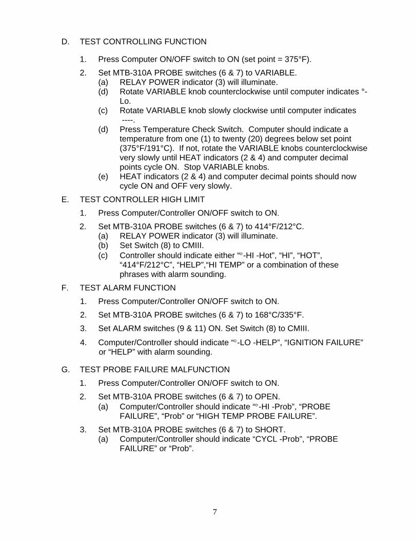
D. TEST CONTROLLING FUNCTION
1. Press Computer ON/OFF switch to ON (set point = 375°F). 2. Set MTB-310A PROBE switches (6 & 7) to VARIABLE.
(a) RELAY POWER indicator (3) will illuminate. (d) Rotate VARIABLE knob counterclockwise until computer indicates °-
Lo. (c) Rotate VARIABLE knob slowly clockwise until computer indicates
----. (d) Press Temperature Check Switch. Computer should indicate a
temperature from one (1) to twenty (20) degrees below set point (375°F/191°C). If not, rotate the VARIABLE knobs counterclockwise very slowly until HEAT indicators (2 & 4) and computer decimal points cycle ON. Stop VARIABLE knobs.
(e) HEAT indicators (2 & 4) and computer decimal points should now cycle ON and OFF very slowly.
E. TEST CONTROLLER HIGH LIMIT 1. Press Computer/Controller ON/OFF switch to ON. 2. Set MTB-310A PROBE switches (6 & 7) to 414°F/212°C.
(a) RELAY POWER indicator (3) will illuminate. (b) Set Switch (8) to CMIII. (c) Controller should indicate either “°-HI -Hot”, “HI”, “HOT”,
“414°F/212°C”, “HELP”,“HI TEMP” or a combination of these phrases with alarm sounding.
F. TEST ALARM FUNCTION 1. Press Computer/Controller ON/OFF switch to ON. 2. Set MTB-310A PROBE switches (6 & 7) to 168°C/335°F. 3. Set ALARM switches (9 & 11) ON. Set Switch (8) to CMIII.
4. Computer/Controller should indicate “°-LO -HELP”, “IGNITION FAILURE” or “HELP” with alarm sounding.
G. TEST PROBE FAILURE MALFUNCTION 1. Press Computer/Controller ON/OFF switch to ON. 2. Set MTB-310A PROBE switches (6 & 7) to OPEN.
(a) Computer/Controller should indicate “°-HI -Prob”, “PROBE FAILURE”, “Prob” or “HIGH TEMP PROBE FAILURE”.
3. Set MTB-310A PROBE switches (6 & 7) to SHORT. (a) Computer/Controller should indicate “CYCL -Prob”, “PROBE
FAILURE” or “Prob”.
8
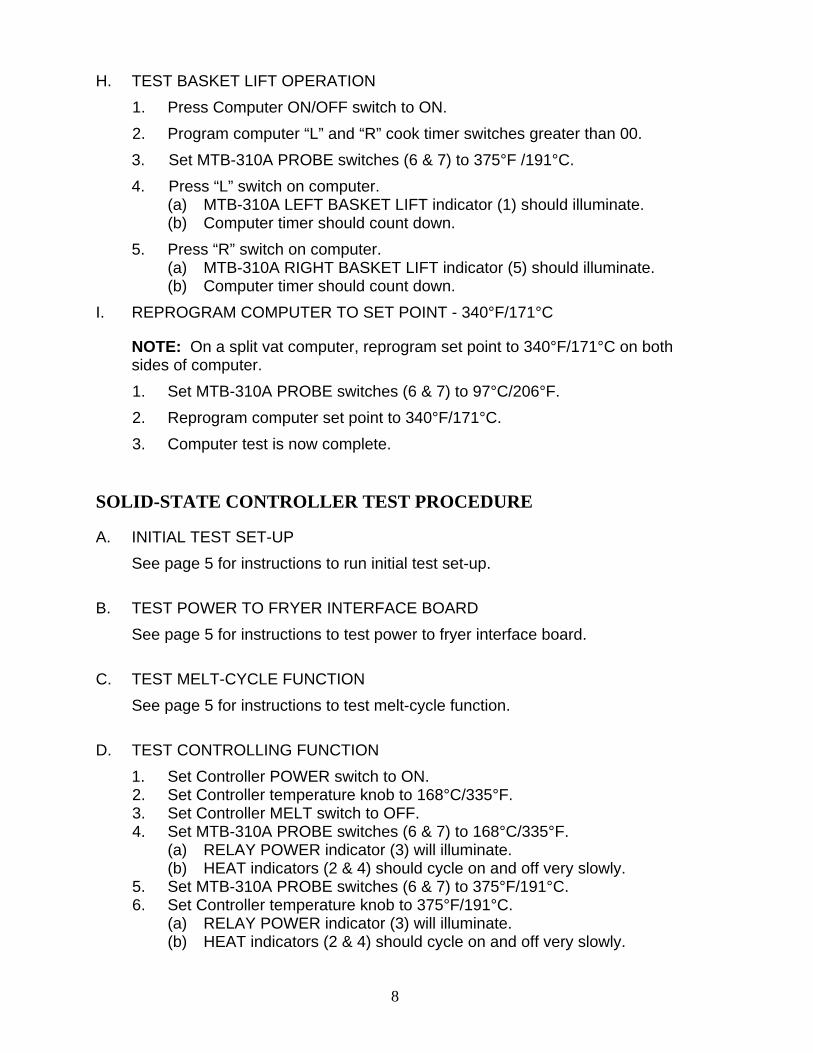
H. TEST BASKET LIFT OPERATION 1. Press Computer ON/OFF switch to ON. 2. Program computer “L” and “R” cook timer switches greater than 00. 3. Set MTB-310A PROBE switches (6 & 7) to 375°F /191°C. 4. Press “L” switch on computer.
(a) MTB-310A LEFT BASKET LIFT indicator (1) should illuminate. (b) Computer timer should count down.
5. Press “R” switch on computer. (a) MTB-310A RIGHT BASKET LIFT indicator (5) should illuminate. (b) Computer timer should count down.
I. REPROGRAM COMPUTER TO SET POINT - 340°F/171°C
NOTE: On a split vat computer, reprogram set point to 340°F/171°C on both sides of computer. 1. Set MTB-310A PROBE switches (6 & 7) to 97°C/206°F. 2. Reprogram computer set point to 340°F/171°C. 3. Computer test is now complete.
SOLID-STATE CONTROLLER TEST PROCEDURE
A. INITIAL TEST SET-UP See page 5 for instructions to run initial test set-up.
B. TEST POWER TO FRYER INTERFACE BOARD See page 5 for instructions to test power to fryer interface board.
C. TEST MELT-CYCLE FUNCTION See page 5 for instructions to test melt-cycle function.
D. TEST CONTROLLING FUNCTION 1. Set Controller POWER switch to ON. 2. Set Controller temperature knob to 168°C/335°F. 3. Set Controller MELT switch to OFF. 4. Set MTB-310A PROBE switches (6 & 7) to 168°C/335°F.
(a) RELAY POWER indicator (3) will illuminate. (b) HEAT indicators (2 & 4) should cycle on and off very slowly.
5. Set MTB-310A PROBE switches (6 & 7) to 375°F/191°C. 6. Set Controller temperature knob to 375°F/191°C.
(a) RELAY POWER indicator (3) will illuminate. (b) HEAT indicators (2 & 4) should cycle on and off very slowly.
9
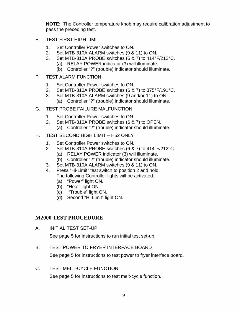
NOTE: The Controller temperature knob may require calibration adjustment to pass the preceding test.
E. TEST FIRST HIGH LIMIT 1. Set Controller Power switches to ON. 2. Set MTB-310A ALARM switches (9 & 11) to ON. 3. Set MTB-310A PROBE switches (6 & 7) to 414°F/212°C.
(a) RELAY POWER indicator (3) will illuminate. (b) Controller “?” (trouble) indicator should illuminate.
F. TEST ALARM FUNCTION 1. Set Controller Power switches to ON. 2. Set MTB-310A PROBE switches (6 & 7) to 375°F/191°C. 3. Set MTB-310A ALARM switches (9 and/or 11) to ON.
(a) Controller “?” (trouble) indicator should illuminate. G. TEST PROBE FAILURE MALFUNCTION
1. Set Controller Power switches to ON. 2. Set MTB-310A PROBE switches (6 & 7) to OPEN.
(a) Controller “?” (trouble) indicator should illuminate. H. TEST SECOND HIGH LIMIT – H52 ONLY
1. Set Controller Power switches to ON. 2. Set MTB-310A PROBE switches (6 & 7) to 414°F/212°C.
(a) RELAY POWER indicator (3) will illuminate. (b) Controller “?” (trouble) indicator should illuminate.
3. Set MTB-310A ALARM switches (9 & 11) to ON. 4. Press “Hi-Limit” test switch to position 2 and hold.
The following Controller lights will be activated: (a) “Power” light ON. (b) “Heat” light ON. (c) “Trouble” light ON. (d) Second “Hi-Limit” light ON.
M2000 TEST PROCEDURE
A. INITIAL TEST SET-UP See page 5 for instructions to run initial test set-up.
B. TEST POWER TO FRYER INTERFACE BOARD See page 5 for instructions to test power to fryer interface board.
C. TEST MELT-CYCLE FUNCTION See page 5 for instructions to test melt-cycle function.
10
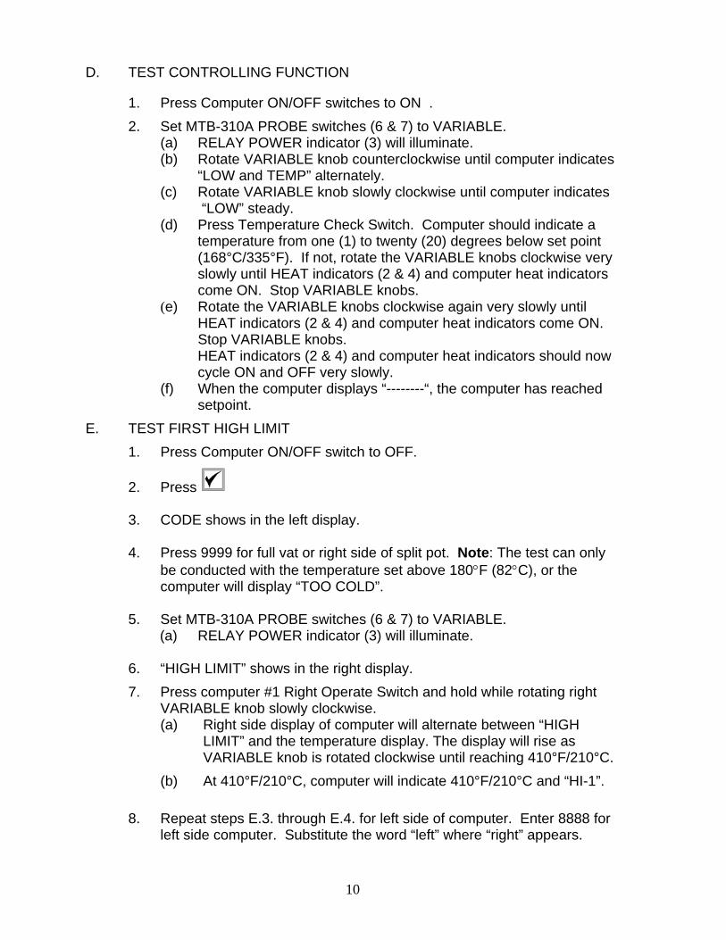
D. TEST CONTROLLING FUNCTION
1. Press Computer ON/OFF switches to ON . 2. Set MTB-310A PROBE switches (6 & 7) to VARIABLE.
(a) RELAY POWER indicator (3) will illuminate. (b) Rotate VARIABLE knob counterclockwise until computer indicates
“LOW and TEMP” alternately. (c) Rotate VARIABLE knob slowly clockwise until computer indicates
“LOW” steady. (d) Press Temperature Check Switch. Computer should indicate a
temperature from one (1) to twenty (20) degrees below set point (168°C/335°F). If not, rotate the VARIABLE knobs clockwise very slowly until HEAT indicators (2 & 4) and computer heat indicators come ON. Stop VARIABLE knobs.
(e) Rotate the VARIABLE knobs clockwise again very slowly until HEAT indicators (2 & 4) and computer heat indicators come ON.
Stop VARIABLE knobs. HEAT indicators (2 & 4) and computer heat indicators should now cycle ON and OFF very slowly.
(f) When the computer displays “--------“, the computer has reached setpoint.
E. TEST FIRST HIGH LIMIT 1. Press Computer ON/OFF switch to OFF.
2. Press
3. CODE shows in the left display.
4. Press 9999 for full vat or right side of split pot. Note: The test can only be conducted with the temperature set above 180°F (82°C), or the computer will display “TOO COLD”.
5. Set MTB-310A PROBE switches (6 & 7) to VARIABLE.
(a) RELAY POWER indicator (3) will illuminate.
6. “HIGH LIMIT” shows in the right display. 7. Press computer #1 Right Operate Switch and hold while rotating right
VARIABLE knob slowly clockwise. (a) Right side display of computer will alternate between “HIGH
LIMIT” and the temperature display. The display will rise as VARIABLE knob is rotated clockwise until reaching 410°F/210°C.
(b) At 410°F/210°C, computer will indicate 410°F/210°C and “HI-1”.
8. Repeat steps E.3. through E.4. for left side of computer. Enter 8888 for left side computer. Substitute the word “left” where “right” appears.
11
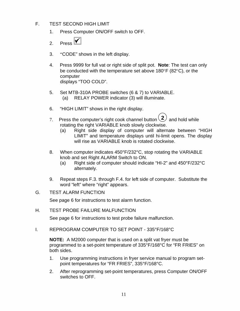
F. TEST SECOND HIGH LIMIT 1. Press Computer ON/OFF switch to OFF.
2. Press
3. “CODE” shows in the left display.
4. Press 9999 for full vat or right side of split pot. Note: The test can only be conducted with the temperature set above 180°F (82°C), or the computer
displays “TOO COLD”.
5. Set MTB-310A PROBE switches (6 & 7) to VARIABLE. (a) RELAY POWER indicator (3) will illuminate.
6. “HIGH LIMIT” shows in the right display.
7. Press the computer’s right cook channel button and hold while
rotating the right VARIABLE knob slowly clockwise. (a) Right side display of computer will alternate between “HIGH
LIMIT” and temperature displays until hi-limit opens. The display will rise as VARIABLE knob is rotated clockwise.
8. When computer indicates 450°F/232°C, stop rotating the VARIABLE
knob and set Right ALARM Switch to ON. (a) Right side of computer should indicate “HI-2” and 450°F/232°C
alternately.
9. Repeat steps F.3. through F.4. for left side of computer. Substitute the word “left” where “right” appears.
G. TEST ALARM FUNCTION See page 6 for instructions to test alarm function.
H. TEST PROBE FAILURE MALFUNCTION See page 6 for instructions to test probe failure malfunction.
I. REPROGRAM COMPUTER TO SET POINT - 335°F/168°C
NOTE: A M2000 computer that is used on a split vat fryer must be programmed to a set-point temperature of 335°F/168°C for “FR FRIES” on both sides. 1. Use programming instructions in fryer service manual to program set-
point temperatures for “FR FRIES”, 335°F/168°C. 2. After reprogramming set-point temperatures, press Computer ON/OFF
switches to OFF.
2
12
DIGITAL CONTROLLER TEST PROCEDURE
A. INITIAL TEST SET-UP See page 5 for instructions to run initial test set-up.
B. TEST POWER TO FRYER INTERFACE BOARD See page 5 for instructions to test power to fryer interface board.
C. TEST MELT-CYCLE FUNCTION See page 5 for instructions to test melt-cycle function.
D. TEST CONTROLLING FUNCTION
1. Press Controller ON/OFF switches to ON (set point = 350°F/177°C). 2. Set MTB-310A PROBE switches (6 & 7) to 350°F/177°C.
(a) RELAY POWER indicator (3) will illuminate. (b) HEAT indicators (2 & 4) and controller heat indicators (decimal
points) should cycle on and off very slowly.
E. TEST CONTROLLER HIGH LIMIT See page 6 for instructions to test controller high limit.
F. TEST ALARM FUNCTION See page 6 for instructions to test alarm function.
G. TEST PROBE FAILURE MALFUNCTION See page 6 for instructions to test probe failure malfunction.
H. REPROGRAM CONTROLLER TO SET POINT – AS NECESSARY
1. Set MTB-310A PROBE switches (6 & 7) to 79°C/175°F. (a) Reprogram controller to desired set-point temperature.
NOTE: On a split vat controller, reprogram set point as necessary on both sides of controller.
13
ELECTRONIC TIMER / BASKET LIFT TEST PROCEDURE
A. INITIAL TEST SET-UP See page 5 for instructions to run initial test set-up.
B. TEST POWER TO FRYER INTERFACE BOARD See page 5 for instructions to test initial power to fryer interface board.
C. TEST MELT-CYCLE FUNCTION See page 5 for instructions to test melt-cycle function.
D. TEST CONTROLLING FUNCTION
1. Press Electronic Timer ON/OFF switches to ON (set point = 350°F/177°C).
2. Set MTB-310A PROBE switches (6 & 7) to 350°F/177°C. (a) RELAY POWER indicator (3) will illuminate. (b) HEAT indicators (2 & 4) and Electronic Timer heat indicators
(decimal points) should cycle on and off very slowly.
E. TEST CONTROLLER HIGH LIMIT See page 6 for instructions to test controller high limit.
F. TEST ALARM FUNCTION See page 6 for instructions to test alarm function.
G. TEST PROBE FAILURE MALFUNCTION See page 6 for instructions to test probe failure malfunction.
H. TEST BASKET LIFT OPERATION 1. Set MTB-310A PROBE switches (6 & 7) to 168°C /335°F. 2. Set MTB-310A ALARM switches (9 & 11) to OFF. 3. Press Electronic Timer ON/OFF switches to ON.
(a) RELAY POWER indicator (3) will illuminate. (b) Both Electronic Timer indicators indicate XXX cook time.
4. Press Electronic Timer cook switches. (a) Both BASKET LIFT indicators (1 & 5) on MTB-310A should
illuminate. (b) Electronic Timer indicators should count down. (c) When Electronic Timer indicators reach 0 time, both BASKET
LIFT indicators (1 & 5) on MTB-310A will go OFF and alarm will sound.
(d) Electronic Timer will indicate “COOC”.
14
5. Press Electronic Timer cook switches. (a) Electronic Timer indicators will return to programmed cook time.
I. REPROGRAM ELECTRONIC TIMER TO SET POINT – AS NECESSARY
NOTE: On a split vat Electronic Timer, reprogram set-point temperature as necessary on both sides of timer.
1. Set MTB-310A PROBE switches (6 & 7) to 79°C/175°F. 2. Set MTB-310A ALARM switches (9 & 11) to OFF. 3. Press Electronic Timer ON/OFF switches to ON.
(a) Reprogram Electronic Timer to desired set-point temperature. 4. Press Electronic Timer ON/OFF switches to OFF. 5. Set MTB-310A POWER switch (10) to OFF.
CM4-S COMPUTER TEST PROCEDURE
A. INITIAL TEST SET-UP See page 5 for instructions to run initial test set-up.
B. TEST POWER TO FRYER INTERFACE BOARD See page 5 for instructions to test initial power to fryer interface board.
C. TEST MELT-CYCLE FUNCTION See page 5 for instructions to test melt-cycle function.
D. TEST CONTROLLING FUNCTION
1. Press Computer ON/OFF switch to ON (set point = 375°F). 2. Set MTB-310A PROBE switches (6 & 7) to VARIABLE.
(a) RELAY POWER indicator (3) will illuminate. (b) Rotate VARIABLE knob counterclockwise until the computer
indicates “LOW”. HEAT indicators (2 & 4) should cycle on and off with the computer heat indicators.
(c) Rotate VARIABLE knob slowly clockwise until the computer indicates ----.
(d) Press the Temperature Check Switch. Computer should indicate a temperature from one (1) to twenty-five (25) degrees below set point (375°F/191°C). If not, rotate the VARIABLE knobs counterclockwise very slowly until the HEAT indicators (2 & 4) and computer decimal points cycle ON. Stop rotating the VARIABLE knobs.
15
(e) HEAT indicators (2 & 4) and computer decimal points should now cycle ON and OFF very slowly.
E. TEST CONTROLLER HIGH LIMIT See page 6 for instructions to test controller high limit.
F. TEST ALARM FUNCTION See page 6 for instructions to test alarm function.
G. TEST PROBE FAILURE MALFUNCTION See page 6 for instructions to test probe failure malfunction.
H. REPROGRAM COMPUTER TO SET POINT - 340°F/171°C
NOTE: On a split vat computer, reprogram set point to 340°F/171°C on both sides of computer. 1. Set MTB-310A PROBE switches (6 & 7) to 97°C/206°F. 2. Reprogram computer set point to 340°F/171°C. 3. Computer test is now complete.
KFC-1 / SMS COMPUTER TEST PROCEDURE A. INITIAL TEST SET-UP
See page 5 for instructions to run initial test set-up.
B. TEST POWER TO FRYER INTERFACE BOARD See page 5 for instructions to test initial power to fryer interface board.
C. TEST MELT-CYCLE FUNCTION See page 5 for instructions to test melt-cycle function.
D. TEST CONTROLLING FUNCTION
1. Press Computer ON/OFF switch to ON (set point = 340°F/171°C). 2. Set MTB-310A PROBE switches (6 & 7) to VARIABLE.
(a) RELAY POWER indicator (3) will illuminate. (b) Rotate VARIABLE knob counterclockwise until computer
indicates “LOW”. HEAT indicators (2 & 4) should cycle on and off with computer heat indicators.
(c) Rotate VARIABLE knob slowly clockwise until computer displays a numerical temperature.
(d) Press Temperature Check Switch. Computer should indicate a temperature from one (1) to eighty-five (85) degrees below set point (340°F/171°C). If not, rotate the VARIABLE knobs counterclockwise very slowly until HEAT indicators (2 & 4) and
16
computer decimal points cycle ON. Stop rotating the VARIABLE knobs.
(e) HEAT indicators (2 & 4) and computer decimal points should now cycle ON and OFF very slowly. The computer will display “DROP”.
E. TEST CONTROLLER HIGH LIMIT See page 6 for instructions to test controller high limit.
F. TEST ALARM FUNCTION See page 6 for instructions to test alarm function.
G. TEST PROBE FAILURE MALFUNCTION See page 6 for instructions to test probe failure malfunction.
H. REPROGRAM COMPUTER TO SET POINT - 340°F/171°C
NOTE: On a split vat computer, reprogram set point to 340°F/171°C on both sides of computer. 1. Set MTB-310A PROBE switches (6 & 7) to 97°C/206°F. 2. Reprogram computer set point to 340°F/171°C. 3. Computer test is now complete.

Frymaster, L.L.C., 8700 Line Avenue, PO Box 51000, Shreveport, Louisiana 71135-1000 Shipping Address: 8700 Line Avenue, Shreveport, Louisiana 71106
TEL 1-318-865-1711 FAX (Parts) 1-318-219-7140
FAX (Tech Support) 1-318-219-7135
PRINTED IN THE UNITED STATES SERVICE HOTLINE 1-800-551-8633
819-5162 MAY 2005