Embed Size (px)
Citation preview

LD18456
R-410A
MODEL JDMA MANUAL FOR MAKEUP AIR CONTROL
OPTION D21
DEDICATED OUTSIDE AIR SYSTEMS (DOAS)
OPERATIONS MANUAL Supersedes: 100.55-O2 (1214) Form 100.55-O2 (1015)
Issue Date: October 2015
AG
ENCY PROCESS
STA
RT-
UP
PRODUCT
CU
STOM
ER
WARRANTY
CONVERGENT
QUALITY SYSTEM
CQSCQS

Example of Unit Controller Display Key Symbols
Example of Remote Controller Display (Option RB5 or RB6) Key Symbols
The function keys will be referred to throughout this manual. The unit controller display or the optional remote display may be used. The function key symbols for Alarm, Prg, and Esc differ on the remote display. See examples below for clarification.
Function Key Identification Alarm Prg Esc Up Enter DownFunction Key Display on the System ControllerFunction Key Display on the Remote Controller
1.1 Display Function Keys
The digital controller has an integral display allowing for complete access to unit test features, schedules, discharge air setpoints, fan control, alarms, and other unit operational setpoints. The control features include:
• Local and remote alarming• Integrated time clock• Compressor anti-cycle protection and minimum “on/off”
cycle rates• Multiple protocol support [BACnet® (MSTP) or LonWorks®]
• Alarm shutdown feature• Commissioning and test mode functions• Optional wall mounted or handheld remote display• Energy conscious applications • TAB menu for creating a backup of setpoints
1.0 Digital Controller
1.0 Digital Controller ............................................11.1 Display Function Keys ...................................11.2 Thermostat Display .......................................21.3 Controller hardware input – output points .....4
2.0 Sequence of Operation .................................52.1 States of Operation .......................................52.2 Modes of Operation .......................................6
3.0 Controls ..........................................................63.1 Supply Fan Control........................................63.2 Exhaust Fan Control......................................83.3 Intake Damper Control ..................................83.4 Temperature And Humidity Control .............103.5 Heating Control ........................................... 113.6 Cooling Control............................................ 113.7 Dehumidification w/ Reheat Compressor ....123.8 Dehumidification w/ AUR2 Modulating Reheat Valve
Arrangement................................................133.9 Energy Recovery .........................................133.10 Space Temp Control & Setpoint Definitions .14
4.0 Safeties and Alarms ....................................154.1 Alarms .........................................................154.2 Alarm Management .....................................19
5.0 Start Up .........................................................225.1 Set the Date, Time on the controller Clock & unit time
schedule ......................................................225.2 Setting the Unit for Operation via the Digital Input
Closure or Time Schedule - Option D21......235.3 Unit Test Mode (includes setting fan cfm) ..235.4 Supply Fan Airflow (cfm) / Pressure Drop (iwc) Table
by Fan and Unit Size ...................................285.5 Power Exhaust PE4 Airflow (cfm) / Pressure Drop
(iwc) Table by Fan and Unit Size .................295.6 Power Exhauxt PE5 Airflow (cfm) / Pressure Drop
(iwc) Table by Fan and Unit Size .................305.7 PE6 Airflow (cfm) / Pressure Drop (iwc) Tables by Fan
and Unit Size ...............................................316.0 Controller History Log .................................327.0 Controller Display Menus ...........................338.0 Communication Cards ................................43
8.1 BACnet® MSTP (Option BHB8) Communication 43
8.2 LonWorks® (Option BHB7) Communication 47Index ...................................................................51
Table of Contents
Applies to: Model JDMAMakeup Air Control Models with Option D21
FORM 100.50-O2 (1015) 2

Mode Button: When pressed
will allow a State Selection of Heat, Cool or
Auto
Fan Button: When pressed will initiate the temporary occupied period.
On / Off Button: When pressed while the unit is in the Heat, Cool, or Auto State, will set the unit State to OFF. When Pressed while the unit is in the Off State, will set the Unit State to the previous Heat, Cool or Auto State.
Set Point Adjustment Dial: For temperature adjustments, press inward on the dial once and turn the dial clockwise to increase and counterclockwise to decrease the desired temperature setpoint. For humidity setpoint adjustments, press the dial inward twice and turn the dial clockwise to increase and counterclockwise to decrease the desired humidity setpoint.
User Space Mounted Thermostat, Option CL78
The user display shall show space temperature, space humid-ity, unit status, and time in its normal state.
1.0 Digital Controller (cont’d) 1.2 Thermostat Display
Optional Space Temperature and Humidity Averaging Feature: Up to 5 space sensors may be added to the control system in addition to the CL78 for a total of 6 space inputs. These devices are combination temperature and humidity sensors and operate on a RS-485 communication trunk.
Space Averaging Sensor Addressable Dip Switch Settings: User must set the addresses accordingly in the field.Note: Refer to the Installation
manual and or unit wiring drawings for specific wiring information.
FORM 100.50-O2 (1015) 3

1 2 3 4 5 6 7 8
ON
1 2 3 4 5 6 7 8
ONRETURN AIR DIP SWITCH
POSITIONS 1 & 7 “ON”
EXHAUST DIP SWITCH
POSITION 7 “ON”
ADDRESS 128RETURN AIR TEMP & HUMIDITY
SENSOR
ADDRESS 129EXHAUST AIR TEMP & HUMIDITY
SENSOR
Exhaust Air / Return Air Temp & Humidity Sensor Addressable Dip Switch Settings: Factory set when ordered on new production units. For retrofits the user must set the addresses accordingly in the field.
Optional Exhaust Air / Return Air Temp & Humidity Sensors: These sensors are duct mount style and operate on a RS-485 communication trunk.
Note: Refer to the Installation manual and or unit wiring drawings for specific wiring information.
FORM 100.50-O2 (1015) 4

1.3 Controller hardware input – output pointsInput
TerminalInput Point
Name Input Description Signal type Signal Range Always Active
J23 FB2
Spc_Temp Space Temp - up to a total of 6 inputs RS-485 CommunicationSpc_Humidity Space Humidity - up to a total of 6 inputs
U1 OA_Hum_Raw Outside Air Humidity 0 -10 Vdc 0 to 100% RH xU2 OA_Temp_Raw Outside Air Temp Thermistor 10K-2 -35 °F to 240 °F (-37°C to 115°C) xU3 EE_Temp Entering Evaporator Temp Thermistor 10K-2 -35 °F to 240 °F (-37°C to 115°C)U4 DA_Temp Discharge Air Temp Thermistor 10K-2 -35 °F to 240 °F (-37°C to 115°C) xU5 CC_Temp Cooling Coil Discharge Air Temp Thermistor 10K-2 -35 °F to 240 °F (-37°C to 115°C) xU6 MA_Temp Mixed Air Temp Thermistor 10K-2 -35 °F to 240 °F (-37°C to 115°C) xU7 Bldg_Pressure Building Static Pressure 0 - 10 Vdc -0.5” iwc thru + 0.5”iwcU8 Duct_Pressure Duct Static Pressure 0 - 10 Vdc 0 - 2.5” iwc U9 Spc_CO2 Space CO2 0 - 10 Vdc 0 - 2,000 ppmU10 ERV_DA_Temp Energy Recovery Wheel Discharge Air Temp Thermistor -35 °F to 240 °F (-37°C to 115°C)J26 FB2
RA_Temp Return Air Temp RS-485 CommunicationRA_Humidity Return Air Humidity
J26 FB2
EA_Temp Exhaust Air Temp RS-485 CommunicationEA_Humidity Exhaust Air Humidity
ID1 SF_Sts Supply Fan Status Dry Contact Open = “OFF” / Close = “ON” xID2 Filter_Sts Main or ERV Dirty Filter Status Dry Contact Open = “OFF” / Close = “ON”ID3 Safety_Sts Safety Input Status Dry Contact Open = “ALARM” / Close = “NORMAL” xID4 Ext_OCC Occupied Mode Input Dry Contact Open = “OFF” / Close = “ON”ID9 Ext_ Switch_1 External Damper Position Sw 1 Dry Contact Open = “OFF” / Close = “ON”ID10 Ext_ Switch_2 External Damper Position Sw 2 Dry Contact Open = “OFF” / Close = “ON”ID11 EF_Sts Exhaust Fan Status Dry Contact Open = “OFF” / Close = “ON”ID12 Comp_Alarm Modulating Compressor General Alarm Dry Contact Open = “OFF” / Close = “ON” xID13 Reheat_Alarm Modulating Reheat Compressor General Alarm Dry Contact Open = “OFF” / Close = “ON”ID14 Phase_Alarm Phase Protection Alarm Dry Contact Open = “OFF” / Close = “ON”
ID15 Htr_1_Sts Gas Heater 1 Status Rib Relay N.O. Contact Open = “OFF” / Close = “ON”
ID16 Htr_2_Sts Gas Heater 2 Status Rib Relay N.O. Contact Open = “OFF” / Close = “ON”
ID17 Spare Spare Spare SpareID18 Spare Spare Spare Spare
Output Terminal Output Point Name Output Description Signal / Range Signal Range Always
EnabledY1 Damper_Cmd Damper Output Command 0 – 10Vdc 0 – 100% OpenY2 SF_VFD_Cmd Supply Fan VFD Command 0 – 10Vdc 0 – 100% FlowY3 Comp_Mod_Cmd DX Modulation Command 1-5 Vdc 0 – 100% Capacity x
Y4 HX_Mod_CmdGas Heating Modulation Command 2 – 10Vdc 0 – 100% CapacityElectric Heating Modulation Command 0 – 10Vdc 0 – 100% Capacity
Y5 RH_Mod_CmdReheat Modulation Command (Pump) 1-5Vdc 0 – 100% CapacityReheat Modulation Command (Valve) 0 – 10Vdc 0 – 100% Capacity
Y6 CF_Spd_Cmd Condenser Fan Speed Command 0-10Vdc Fixed at 90% SpeedNO1 SF_Cmd Supply Fan Command 24Vac Contact Open = “OFF” / Close = “ON” xNO2 Comp_Stg2_Cmd Compressor Stage 2 Command 24Vac Contact Open = “OFF” / Close = “ON”NO3 Comp_Stg3_Cmd Compressor Stage 3 Command 24Vac Contact Open = “OFF” / Close = “ON”NO4 Comp_Stg4_Cmd Compressor Stage 4 Command 24Vac Contact Open = “OFF” / Close = “ON”NO5 Cond_A_Cmd Condenser Section A Command 24Vac Contact Open = “OFF” / Close = “ON” xNO6 Cond_B_Cmd Condenser Section B Command 24Vac Contact Open = “OFF” / Close = “ON”NO7 Alm_Rly_Cmd Unit General Alarm Relay Command 24Vac Contact Open = “OFF” / Close = “ON” xNO8 HX_Stg1_Cmd Heating Stage 1 Command 24Vac Contact Open = “OFF” / Close = “ON”NO9 HX_Stg2_Cmd Heating Stage 2 Command 24Vac Contact Open = “OFF” / Close = “ON”NO10 HX_Stg3_Cmd Heating Stage 3 Command 24Vac Contact Open = “OFF” / Close = “ON”NO11 HX_Stg4_Cmd Heating Stage 4 Command 24Vac Contact Open = “OFF” / Close = “ON”NO12 HX_Stg5_Cmd Heating Stage 5 Command 24Vac Contact Open = “OFF” / Close = “ONNO13 HX_Stg6_Cmd Heating Stage 6 Command 24Vac Contact Open = “OFF” / Close = “ON”NO14 spare spare spare spareNO15 ERV_Cmd Energy Recovery Wheel Command 24Vac Contact Open = “OFF”/ Close = “ON”NO16 Preheat_Cmd Electric Preheat Command 24Vac Contact Open = “OFF” / Close = “ON”NO17 spare spare spare spareNO18 spare spare spare spareJ25
BMS2EF_Cmd Exhaust Fan Cmd RS-485
CommunicationEF_Spd_Cmd Exhaust Fan Speed Command
FORM 100.50-O2 (1015) 5
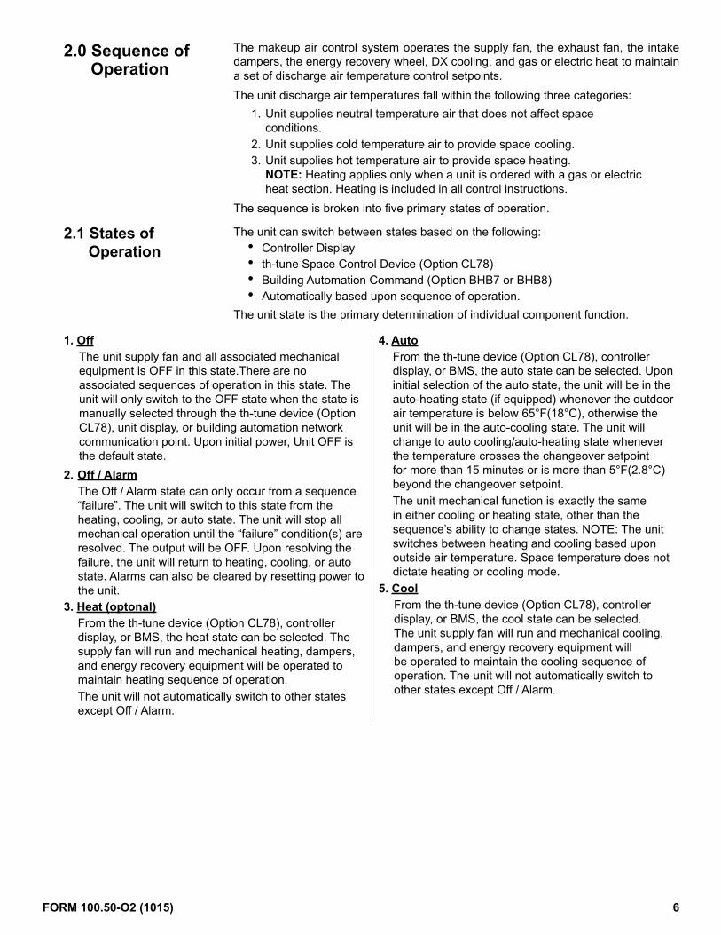
The makeup air control system operates the supply fan, the exhaust fan, the intake dampers, the energy recovery wheel, DX cooling, and gas or electric heat to maintain a set of discharge air temperature control setpoints.The unit discharge air temperatures fall within the following three categories:
1. Unit supplies neutral temperature air that does not affect space conditions.
2. Unit supplies cold temperature air to provide space cooling.3. Unit supplies hot temperature air to provide space heating.
NOTE: Heating applies only when a unit is ordered with a gas or electric heat section. Heating is included in all control instructions.
The sequence is broken into five primary states of operation.
2.0 Sequence of Operation
2.1 States of Operation
The unit can switch between states based on the following:• Controller Display• th-tune Space Control Device (Option CL78)• Building Automation Command (Option BHB7 or BHB8)• Automatically based upon sequence of operation.
The unit state is the primary determination of individual component function.
1. OffThe unit supply fan and all associated mechanical equipment is OFF in this state.There are no associated sequences of operation in this state. The unit will only switch to the OFF state when the state is manually selected through the th-tune device (Option CL78), unit display, or building automation network communication point. Upon initial power, Unit OFF is the default state.
2. Off / AlarmThe Off / Alarm state can only occur from a sequence “failure”. The unit will switch to this state from the heating, cooling, or auto state. The unit will stop all mechanical operation until the “failure” condition(s) are resolved. The output will be OFF. Upon resolving the failure, the unit will return to heating, cooling, or auto state. Alarms can also be cleared by resetting power to the unit.
3. Heat (optonal)From the th-tune device (Option CL78), controller display, or BMS, the heat state can be selected. The supply fan will run and mechanical heating, dampers, and energy recovery equipment will be operated to maintain heating sequence of operation.The unit will not automatically switch to other states except Off / Alarm.
4. AutoFrom the th-tune device (Option CL78), controller display, or BMS, the auto state can be selected. Upon initial selection of the auto state, the unit will be in the auto-heating state (if equipped) whenever the outdoor air temperature is below 65°F(18°C), otherwise the unit will be in the auto-cooling state. The unit will change to auto cooling/auto-heating state whenever the temperature crosses the changeover setpoint for more than 15 minutes or is more than 5°F(2.8°C) beyond the changeover setpoint.The unit mechanical function is exactly the same in either cooling or heating state, other than the sequence’s ability to change states. NOTE: The unit switches between heating and cooling based upon outside air temperature. Space temperature does not dictate heating or cooling mode.
5. CoolFrom the th-tune device (Option CL78), controller display, or BMS, the cool state can be selected. The unit supply fan will run and mechanical cooling, dampers, and energy recovery equipment will be operated to maintain the cooling sequence of operation. The unit will not automatically switch to other states except Off / Alarm.
FORM 100.50-O2 (1015) 6

Occupied & UnoccupiedWhen the unit is called to operate in the auto, heating, or cooling state(s), the unit will function in one of two modes: occupied or unoccupied. The unit will run in occupied or unoccupied mode based upon one of the following three user selected commands:
1. Internal Time Clock Schedule Selects Occupied or Unoccupied Mode.2. Physical input point (ID4) (Contact closed = Occupied)3. Building Automation network variable (LonWorks® or BACnet®)
From the display, the user will select the mode control type. All other input methods are ignored.
Heating Sequence1. Supply Fan = ON
2. Dampers = Mod3. Heat = ON/Mod
Discharge Air Temperature Setpoint 1. Neutral Air = 70°F (21°C) 2. Space Heat = 90°F (32°C)
Manual Heating State
ModeOcc or Unocc
Unit OFF Requires
Reset
Manual Cooling State
Unit TestMode
No ControlAll Mechanical
Equipment = OFFAll Outputs OFF
or Zero State
1. Supply Fan(s) = Intermittent when th-Tune Device is enabled. See Note 1.
2. Dampers = ClosedSee Note 2.Discharge Air
Temperature Setpoint 1. Space Heat = 90°F (32°C)
Cooling Sequence1. Supply Fan = ON
2. Dampers = Mod3. Cooling = ON/Mod4. Dehum = Allowed
Discharge Air Temperature Setpoint 1. Neutral Air = 70°F (21°C)2. Space Cool = 55°F (12°C)
ModeOcc or Unocc
1. Supply Fan(s) = Intermittent when th-Tune Device is enabled. See Note 1.
See Note 2. 2. Dampers = Closed
3. Dehumid = Allowed
1. Space Cool = 55°F (12°C)
Auto Heat / Cool State
Outside Air Temp >65°F
(18°C)
Control System Unit State, Mode, Major DAT Septoint
Off / AlarmState
Unit OFFState
Heating Sequence Cooling Sequence
Discharge Air Temperature Setpoint
No Yes
State
Mode
FunctionUnocc ModeOcc ModeUnocc ModeOcc Mode
NOTE 1. Intermittent operation of the supply fan will be based on an increased space cooling setpoint and a decreased space heating setpoint during the unoccupied mode.NOTE 2. For damper control options GF1 & GF2 damper operation will be permitted when the unoccupied ventilation variable is set to on.
User has pseudo manual
control of all mechanical operation
Tab:FunctionSet Fan Speeds
2.0 Sequence of Operation (Cont’d)
3.1 Supply Fan Control
The supply fan provides the total volume of conditioned air to the space at a given rate. The rate is controlled by unit state, mode, and the selection of one of the six sequences of operation.1. High Low Volume Control (Option VFC1)2. Duct Static Pressure (Option VFC3)3. Building Static Pressure (Option VFC4)4. Summer/Winter Constant Volume (Option VFC9)5. External Source 0 to 10 vdc (VFC2)6. BMS Source (VFCC)
3.0 Controls
2.2 Modes of Operation
FORM 100.50-O2 (1015) 7

Manual Heating State
ModeOcc or Unocc
Unit OFFState
Control System Unit State, Mode, Major DAT Septoint
Manual Cooling State
Off / AlarmState
Unit TestMode
Fan = OFF
ModeOcc or Unocc
Auto Heat / Cool State
Outside Air Temp >65°F
(18°C)
Fan = OFF Fan = IntermittentSee Note 1.
Fan = ON and Speed = to Maximum
Speed Setpoint
Fan = ON Fan = ON
Occ Mode Unocc Mode Unocc ModeOcc Mode
Fan = IntermittentSee Note 1.
No Yes
State
Mode
Fan Function
NOTE 1. - Intermittent operation of the supply fan will be based on an increased space cooling setpoint and a decreased space heating setpoint during the unoccupied mode.
Supply Fan Control: Occupied Mode
When the unit is called to be in occupied mode, the supply fan will start. If the unit is configured with a 100% outside air damper, the damper actuator is electrically inter-locked such that the supply fan cannot start until the damper is 80% open.When the Supply fan is commanded OFF, any active heating or cooling operations will be shut down and the supply fan will stop after an adjustable time delay.The rate is controlled by unit state, mode, and the selection of one of six sequences of operation:1. High - Low Fan Speed Control (VFC1) The variable frequency drive is
commanded ON from NO1. There are two fan speed states - active heating/cooling and fan only. When the fan is ON and the system is in either the space heating or space cooling mode, the unit will operate on high fan speed. When the fan is ON and the system is not in either the space cooling or space heating mode, the supply fan will operate on low fan speed.
2. Duct Static Pressure Control (0.0” to 2.5” iwc) (Option VFC3) The variable frequency drive is commanded ON from NO1. The fan modulates between the user adjustable minimum and maximum fan speed setpoints using a PI loop to maintain the duct static pressure setpoint, +0.5”iwc default.
3. Building Static Pressure Control (-0.5” to 0.5” iwc) (Option VFC4) The variable frequency drive is commanded ON from NO1. The fan modulates between the user adjustable minimum and maximum fan speed setpoints using a PI loop to maintain the building static pressure setpoint, +0.1”iwc default.
4. Summer/Winter Constant Volume (Option VFC9) The variable frequency drive is commanded ON from NO1. The unit ramps up to a user set supply fan speed setting. There are two individual supply fan speed % setpoints, one for heating and one for cooling. When the Unit is in Space or Neutral air Heating, the supply fan will use the heating speed % setpoint. When the unit is in any other mode, the supply fan will use cooling speed % setpoint.
5. External Source 0 to 10 vdc (VFC2) The variable frequency drive is commanded ON from NO1. The supply fan will modulate from 0-100%. The speed control sig-nal is sourced by others and a direct connection of a 0 to 10 vdc input to the unit terminal strip must be provided.
6. BMS Source (VFCC) The variable frequency drive is commanded ON from NO1. The dampers will modulate from 0-100%. The speed control signal is sourced by others, communicated via a BMS network and a connection to either a BHB7 or BHB8 BMS card is required.
A 30-second acceleration and deceleration rate for the supply fan to ramp between the minimum and maximum motor frequency is factory set via the unit variable frequency drive.
FORM 100.50-O2 (1015) 8

3.3 Intake Damper Control
The intake dampers operate based upon state, mode, and one of five user selected sequences. The dampers are normally open and operational in the occupied mode and closed to outside air in the unoccupied mode depending on the user selection. The five sequences are:1. 100% OA, (Option GF2A)
When the unit is to start, the outside air damper will modulate (point Y1 = 10Vdc) and the supply fan will be commanded ON (point NO1 = On). If the unit is equipped with an outside air damper, the damper actuator is electrically interlocked to the fan start/stop such that the supply fan cannot start until the damper is 80% open. Air inlet configuration Options AR8, AR2D, AR2L, and AR2Y are electrically interlocked with the supply fan.
OFF and Alarm Modes - The damper will be closed. Y1 = 0%.2. External 0-10vdc Input, (Option GF1) Occupied & Unoccupied Mode
The dampers will modulate from 0-100%. The control signal is sourced by others and a direct connection of a 0 to 10 vdc input to the unit terminal strip must be provided. This option is not allowed with air inlet configuration Options AR8, AR2D, AR2L, and AR2Y. The software does not prevent the selection of this option. The fan status switch will handle the block flow condition. The damper is NOT electrically interlocked with the supply fan.
Exhaust Fan Control: Occupied Mode1. High - Low Fan Speed Control (EFC1)
The ECM motor is commanded via Modbus communication. There are two fan speed states - active heating/cooling and fan only. When the fan is ON and the system is in either the space heating or space cooling mode, the unit will operate on high fan speed. When the fan is ON and the system is not in either the space cooling or space heating mode, the supply fan will operate on low fan speed.
2. Building Static Pressure Control (-0.5” to 0.5” iwc) (Option EFC4)The ECM motor is commanded via Modbus communication. The fan will operate between the user adjustable minimum and maximum fan speed setpoints, and modulate using a PI loop to maintain the building static pressure setpoint, +0.1”iwc default.
3. Supply Fan Tracking (Option EFC7) NOTE: This option is not available with supply fan control option External Source 0 to 10 vdcThe ECM motor is commanded via Modbus communication. This option will use an offset variable to subtract from the commanded supply fan speed. The difference between the supply fan speed minus the value of the offset variable will be the active exhaust fan speed setpoint.
4. Constant Volume (Option EFC9)The ECM motor is commanded via Modbus communication. The unit ramps up to a user set exhaust fan speed setting. There are two individual exhaust fan speed % setpoints, one for heating and one for cooling. When the unit is in Space or Neutral Air Heating, the exhaust fan will use the heating speed % setpoint. When the unit is in any other mode, the exhaust fan will use cooling speed % setpoint.The exhaust fan has a 30-second acceleration and deceleration rate to ramp between the minimum and maximum speeds.
The exhaust fan is normally OFF in the unoccupied mode. The unit exhaust fan will be permitted to operate in the unoccupied mode if the unit is configured for 100% outside air. Exhaust fan operation will also be permitted when the intake damper control options GF1, GF2 or control by BMS is selected and the unoccupied ventilation enable variable is set to ON.
3.0 Controls (Cont’d)Supply Fan Control : Unoccupied Mode
When configured for space control, the supply fan operation will be intermittent based on the zone temperature. See Temperature and Humidity Control section, Paragraph 3.9, for space control and setpoint definition.
3.2 Exhaust Fan Control
The exhaust fan provides a volume of air expelled to outdoors. The rate is controlled by unit state, mode, and the selection of one of four sequences of operation.
Exhaust Fan Control Unoccupied Mode
FORM 100.50-O2 (1015) 9

3. Two-Position Dampers (Option GF2) Occupied Mode
The damper will open to the user adjustable occupied damper position setpoint value (point Y1=10Vdc). For the damper options with only 100% outside air, the mechanical interlock of 80% will not allow the fan to start. Adjust the outside air setpoint to reach the minimum electrical interlock position.
Unoccupied ModeWith the unoccupied ventilation enable variable set to ON, the damper will open to the user adjustable unoccupied damper position setpoint value (point Y1=0Vdc). For the damper options with only 100% outside air, the mechanical interlock of 80% will not allow the fan to start. Adjust the outside air setpoint to reach the minimum electrical interlock position. With the unoccupied ventilation enable variable set to OFF, the damper will be commanded to 0%.
OFF and Alarm Modes - The damper will be closed. Y1 = 0%.4. Four Positions based on 2 Digital Inputs (Option GF4) Occupied Mode
The damper will open to the user adjustable defined position based upon two hardware input switches (ID9 & ID10).
Variable Name Input Switch Default Damper Position
Display Range
Y1 Output RangeID9 ID10
Aux_1_SP Open Open 20% 0-100% 0 – 10VAux_2_SP Close Open 40% 0-100% 0 – 10VAux_3_SP Open Close 60% 0-100% 0 – 10VAux_4_SP Close Close 80% 0-100% 0 – 10V
This option is not allowed with AR8, AR2D, AR2L, and AR2Y. The software does not prevent the selection of this option. The fan status switch will handle the block flow condition.Unoccupied, OFF and Alarm Modes -The damper will be closed ( Y1 = 0%).
5. Building Pressure Control (Range -0.5 to 0.5” iwc) (Option GF5) Occupied Mode
The dampers will modulate using a PI loop to maintain the building static pressure setpoint, default 0.1” iwc Y1 will modulate from 0-100% open, 0-10V.
Unoccupied, OFF and Alarm Modes - The damper will be closed (Y1 = 0%). 6. BMS Source (Otion GF1A)
The dampers will modulate from 0-100%. The damper control signal is sourced by others, communicated bia a BMS network and a connection to either a BHB7 or BHB8 BMS card is required.
FORM 100.50-O2 (1015) 10

Discharge Air Temperature (DAT) Setpoint Decision Tree
Space Temperature Control Req’d Initiate: Space Temp 4°F(2.1°C) > SpcEffClgSP
Release: Space Temp 1°F(.4°C) < SpcEffClgSPDAT Setpoint = 55°F(12°C); 50-100°F(10-37°C)
Space Humidity Control Req’dInitiate: Space %RH 10% > Setpoint
Release: Space %RH 5% < Setpoint Space %RH Setpoint = 55%; 35-75%
DAT Sp = 70°F(21°C); 50-100°F(10-37°C) Main Coil Setpoint CC-T = 52°F(11°C)
Required State•Heat•Cool•Auto
(Unit cycles ON based on Space Temperature Control.)
DAT Setpoint = 90°F(32°C); 50-100°F(10-37°C)Space Heating Required
HEATING
Space Cooling Required
Neutral Air Temperature Control DAT Sp = 70°F(21°C); 50-100°F(10-37°C)
COOLING
Space Temperature Control Req’dInitiate: Space Temp 4°F(2.1°C) > SpcEffClgSP Release: Space Temp 1°F(.4°C) < SpcEffClgSP
DAT Setpoint = 55°F(12°C); 50-100°F(10-37°C)(Unit Cycles ON based on
Space Temperature Control.)
Occ Mode
Unocc Mode
Space Dehumidification
Required
Occ Mode
Unocc Mode
Space Cooling Required Initiate: Space Temp 5°F(2.8°C) > SpcHtgSP
Release: Space Temp 1°F(.4°C) < SpcHtgSPDAT Setpoint = 55°F(12°C); 50-100°F (10-37°C)(Auto Heating Only)
Occ Mode
Unocc Mode
Occ Mode
Unocc Mode
YES YES
YES YES
Unit Off
NO
NO
Occ Mode
Unocc Mode
Neutral Air Dehumidification ControlReq’d Dehum OAT Dewpoint > 58°F(14°C);
48-90°F(8-32°C) DAT Setpoint = 70°F(21°C);
50-100°F(10-37°C)Main Coil Setpoint CC-T = 52°F(11°C)
Neutral Air Temperature Control
Neutral Air Dehum
Req’d
NO
Unit Off
YES
NO
NO
* If the space temperature sensor (th-Tune) is not enabled or fails, the logic will ignore the space requirements and operate to maintain neutral air temperature and neutral air dehumidification control. If the th-Tune is enabled and fails, an alarm condition is created.
Occ Mode
Unocc Mode
Space Humidity Control Req’dInitiate: Space %RH 10% > Setpoint Release: Space %RH 5% < Setpoint
Space %RH Setpoint = 55%; 35-75%DAT Sp = 70°F(21°C); 50-100°F(10-37°C)
(Unit cycles on based upon Space Dehumidification Control.)
Main Coil Setpoint CC-T = 52°F(11°C)
DAT Setpoint = 70°F(21°C); 50-100°F(10-37°C)
Space Temperature Control Req’dInitiate: Space Temp 4°F(2.1°C) > SpcEffHtgSPRelease: Space Temp 1°F(.4°C) < SpcEffHtgSP
DAT Setpoint = 90°F(32°C); 50-100°F(10-37°C)
Space Temperature Control Req’dInitiate: Space Temp 4°F(2.1°C) > SpcEffHtgSPRelease: Space Temp 1°F(.4°C) < SpcEffHtgSP
Space Temperature Control Req’d
Or Sliding Scale
Unit Off
Reset ScheduleOutside Air
TemperatureDischarge Air Temperature
30°F (-1.1°C)
75°F (23.8°C)
65°F (18.3°C)
65°F (18.3°C)
Sliding Scale: Temperature Reset Schedule Setpoint (heating Only)The user can also select a reset schedule for the discharge setpoint used when in neutral air heating mode.
3.0 Controls (Cont’d)
3.4 Temperature And Humidity Control
The unit is inherently a discharge air temperature control system. The unit will oper-ate to maintain one of the following discharge air setpoints depending on the state and mode. Selected setpoints are user adjustable from the unit display and the wall mounted user interface.
FORM 100.50-O2 (1015) 11

3.5 Heating Control A call for mechanical heat will occur when the discharge air temperature is 5°F(2.8°C) below the active setpoint. When the OAT is below 65°F/18°C (Heating Lockout SP), the unit enables the mechanical heat to maintain the active setpoint. The modulated heat output (gas or electric) will be set to 24% output and NO8 will be ON. The system will remain in this state for 30 seconds. After the initial timer has expired, the unit will stage as shown in the staging chart and the PI loop will activate. Stages should be assumed cumulative from the previous stage.
Gas or Electric Heat StagingPI Loop Control: All Statements Must Be True To Activate or De-Activate.
All stages will have an adjustable min ON and OFF time.
Stage OutputsIncrease Inter-Stg
TimerActivate
De-activate(No timers to de-activate except as shown.)
Stg 1Y4 = 24% for 30 seconds & NO8 = ON
DAT 5°F (2.8°C) below set-point (Y4 Modulates, PI Loop)
Y4 < 2.5% Modulation & DAT 5°F (2.8°C) above setpoint for 10 mins
Stg 2 NO9 = ON 5 min Y4 > 70% Modulation & DAT 5°F(2.8°C) below setpoint
Y4 < 5% Modulation & DAT 5°F(2.8°C) above setpoint
Stg 3 NO10 = ON 5 min Y4 > 75% Modulation & DAT 5°F(2.8°C) below setpoint
Y4 < 10% Modulation & DAT 5°F(2.8°C) above setpoint
Stg 4 NO11 = ON 5 min Y4 > 80% Modulation & DAT 5°F(2.8°C) below setpoint
Y4 < 20% Modulation & DAT 5°F(2.8°C) above setpoint
Stg 5 NO12 = ON 5 min Y4 > 85% Modulation & DAT 5°F(2.8°C) below setpoint
Y4 < 30% Modulation & DAT 5°F(2.8°C) above setpoint
Stg 6 NO13 = ON 5 min Y4 > 90% Modulation & DAT 5°F(2.8°C) below setpoint
Y4 < 40% Modulation & DAT 5°F(2.8°C) above setpoint
All parameters are factory level access.
When the unit has a call for cooling from the th-tune device (Option CL78) in the space, it will use the unit U4 DAT input and Y3 to achieve the space cooling discharge air temperature setpoint. A call for space cooling takes priority over a call for space dehumidification.A call for mechanical cooling Y3 will occur when the discharge air temperature is 5°F(2.8°C) above the active setpoint. When the OAT is above 65°F/18°C (Cooling Lockout SP), the unit enables the mechanical cooling Y3 to maintain the active setpoint. Cooling capacity/staging will follow a PI loop to maintain the active setpoint, Y3= 1-5V, 0-100% Capacity, Y3 = 1V is an OFF condition.Space Cooling Active = Space dehumidification Y5 Reheat_Mod_Capacity Control not permitted.Space Cooling Inactive = Space dehumidification Y5 Reheat_Mod_Capacity Control permitted. If Space Cooling is inactive and the space humidity is above the space dehumidification setpoint, the unit will enter the space dehumidification mode. While in the space dehumidification mode, the Y3 compressor output will be enabled to maintain a 52°F(11°C) cooling coil discharge setpoint and will use the U5 CC_Temp sensor. See dehumidification commands section for details on the operation of the reheat compressor Y5 output in space dehumidification mode.
3.6.1 Cooling Control Y3 (with the Option CL78 th-tune device ENABLED and COMMUNICATING)
3.6 Cooling Control
FORM 100.50-O2 (1015) 12

The unit will use the U4 DAT input and Y3 to achieve the neutral discharge air temperature setpoint.A call for mechanical cooling will occur when the discharge air temperature is 5°F(2.8°C) above the neutral air setpoint. When the OAT is above 65°F/18°C (Cooling Lockout SP), the unit enables the mechanical cooling Y3 to maintain the neutral air setpoint. Cooling capacity/staging will follow a PI loop to maintain the active setpoint, Y3= 1-5V, 0-100% Capacity, Y3 = 1V is an OFF condition.When the OA dewpoint is greater than 58°F(14°C) the unit will enter the neutral air dehumidification mode. While in the neutral air dehumidification mode, the Y3 com-pressor output will be enabled to maintain a 52°F(11°C) cooling coil discharge set-point and will use the U5 CC_Temp sensor. See dehumidification commands section for details on the operation of the reheat compressor Y5 output in the neutral air dehu-midification mode.
DX Mechanical Cooling StagingPI Loop Control: All Statements Must Be True To Activate or De-Activate
All stages will have an adjustable min ON and OFF time
Stage Output Compressor / Condenser
Inter Stage Timing Activate De-activate
Stg 1 Y3 A 5 min 0 – 70% Modulation DAT 5°F(2.8°C) above setpoint
< 10 % Modulation DAT 5°F(2.8°C) below setpoint
Stg 2 NO2 A & B 5 min > 70% Modulation & DAT 5°F(2.8°C) above setpoint
< 50% Modulation & DAT 5°F(2.8°C) below setpoint
Stg 3 NO3 A, B & C 5 min > 80% Modulation & DAT 5°F(2.8°C) above setpoint
< 55% Modulation & DAT 5°F(2.8°C) below setpoint
Stg 4 NO4 A, B, C & D 5 min > 90% Modulation & DAT 5°F(2.8°C) above setpoint
< 60% Modulation & DAT 5°F(2.8°C) below setpoint
NO5 Cond_Sec_A - When Y3 > 0% When Y3 = 0%, OFF
NO6 Cond_Sec_B - When NO2, NO3, or NO4 = ON
When NO2, NO3, or NO4 = OFF
All parameters are factory level access.
3.7 Dehumidification with Reheat Compressor
Dehumidification CommandsWhen either the space dehumidification mode or the neutral air dehumidification mode are active, the main evaporator compressor(s) will be enabled to maintain a 52°F(11°C) cooling coil discharge setpoint and will use the U5 CC_Temp sensor. The reheat pump Y5 will be enabled to modulate to maintain the reheat setpoint 70°F(21°C) via the U4 DAT temp sensor, Y5= 1-5V, 0-100% Capacity, Y5 = 1V is an OFF condition.
Any of the following conditions will lockout the space dehumidification Mode:1. The outdoor air temperature is below the reheat lockout setpoint, (58°F/14°C,
reheat lockout, range 50-100°F/10-37°C) Drybulb.2. The outdoor air temperature is above the reheat high lockout setpoint.
(100°F/37°C, reheat high lockout, range 50-120°F/10-48°C) Drybulb3. The space cooling mode is active.4. Cooling Coil Sensor failure.Any of the following conditions will lockout the neutral air dehumidification Mode:1. The outdoor air temperature is below the reheat lockout setpoint, (58°F/14°C,
reheat lockout, range 50-100°F/10-37°C) Drybulb2. The outdoor air temperature is above the reheat high lockout setpoint.
(100°F/37°C), reheat high lockout, range 50-120°F/10-48°C) Drybulb3. Outside Air Humidity Sensor or Cooling Coil Sensor failure.4. OA dewpoint less than 58°F(14°C).
3.0 Controls (Cont’d)3.6 Cooling Controls (Cont’d)
3.6.2 Cooling Control Y3 (with the Option CL78 th-tune device DISABLED and NOT COMMUNICATING)
FORM 100.50-O2 (1015) 13

3.8 Dehumidification with AUR2 Modulating Reheat Valve Arrangement
Dehumidification CommandsWhen either the space dehumidification mode or the neutral air dehumidification mode are active, the main evaporator compressor(s) will be enabled to maintain a 52°F(11°C) cooling coil discharge setpoint and will use the U5 CC_Temp sensor. The reheat valve arrangement Y5 will be enabled to modulate to maintain the reheat setpoint 70°F(21°C) via the U4 DAT temp sensor, Y5= 0-10V, 0-100% Capacity.
Any of the following conditions will lockout the space dehumidification Mode:1. The outdoor air temperature is below the reheat lockout setpoint, (58°F/14°C,
reheat lockout, range 50-100°F/10-37°C) Drybulb.2. The outdoor air temperature is above the reheat high lockout setpoint.
(100°F/37°C, reheat high lockout, range 50-120°F/10-48°C) Drybulb3. The space cooling mode is active.4. Cooling Coil Sensor failure.5. Entering Evaporator Temp Sensor failure.Any of the following conditions will lockout the neutral air dehumidification Mode:1. The outdoor air temperature is below the reheat lockout setpoint, (58°F/14°C,
reheat lockout, range 50-100°F/10-37°C) Drybulb2. The outdoor air temperature is above the reheat high lockout setpoint.
(100°F/37°C), reheat high lockout, range 50-120°F/10-48°C) Drybulb3. Outside Air Humidity Sensor or Cooling Coil Sensor failure.4. OA dewpoint less than 58°F(14°C). 5. Entering Evaporator Temp Sensor failure.
Energy Recovery Economizer Operation (Default Control Setting)The energy recovery wheel will operate whenever the exhaust fan is ON in any mode and when the outside air temperature is not within a 5°F band of the active discharge air temperature setpoint for the unit. When the energy recovery wheel is disabled due to the economizer the wheel will be started and will run for a period of 5 minutes every 3 hours for cleaning purposes. In the event of an exhaust fan failure, the energy recovery wheel ERV will not be permitted to operate.The optional energy recovery preheat NO16 will operate whenever the ERV supply air temperature is less than 33°F/1°C (with a two degree differential) and the outdoor air temperature is below 32°F/0°C (with a two degree differential). Otherwise the electric preheat is OFF.In the event that the ERV Supply Air Temp Sensor fails, the energy recovery preheat will not be permitted to operate.
Energy Recovery Continuous Operation (Optional)The energy recovery wheel will operate whenever the exhaust fan is ON in any mode.In the event of an exhaust fan failure, the energy recovery wheel ERV will not be per-mitted to operate.The optional energy recovery preheat NO16 will operate whenever the ERV supply air temperature is less than 33°F/1°C (with a two degree differential) and the outdoor air temperature is below 32°F/0°C (with a two degree differential). Otherwise the electric preheat is OFF.In the event that the ERV Supply Air Temp Sensor fails, the energy recovery preheat will not be permitted to operate.
3.9 Energy Recovery
FORM 100.50-O2 (1015) 14

3.10 Space Temperature Control and Setpoint Definitions
3.0 Controls (Cont’d)
3.10.1 Occupied Space Temperature Control and Setpoint DefinitionsHeatingSpcTempSP: Base Space Temp Setpoint 72°F(22°C) minus the SpcHtgDB: Space Heating Dead Band 1°F(.4°C) = SpcHtgSP: Space Heating Setpoint 71°F(21°C)When in the occupied mode, the SpcHtgSP: Space Heating Setpoint is the SpcEffHtgSp: Space Effective Heating Setpoint.SpcEffHtgSp: Space Effective Heating Setpoint 71°F(21°C) minus the SpcHtgOnDiff: Space Heating on Differential 4°F(2.1°C) = 67°F(19°C)Space Temp less than or equal to 67°F(19°C) = Space Heating Mode ON. SpcEffHtgSp: Space Effective Heating Setpoint 71°F (21°C) plus the SpcHtgOffDiff: Space Heating off Differential 1°F(.4°C) = 72°F(22°C)Space Temp greater than or equal to 72°F(22°C) = Space Heating Mode OFF.CoolingSpcTempSP: Base Space Temp Setpoint 72°F(22°C) plus the SpcClgDB: Space Cooling Dead Band 1°F(.4°C) = SpcClgSP: Space Cooling Setpoint 73°F(23°C)When in the occupied mode, the SpcClgSP: Space Cooling Setpoint is the SpcEffClgSp: Space Effective Cooling Setpoint.SpcEffClgSp: Space Effective Cooling Setpoint 73°F(23°C) plus the SpcClgOnDiff: Space Cooling on Differential 4°F(2.1°C) = 77°F(25°C)Space Temp greater than or equal to 77°F(25°C) = Space Cooling Mode ON. SpcEffHtgSp: Space Effective Cooling Setpoint 73°F(23°C) minus the SpcClgOffDiff: Space Cooling off Differential 1°F(.4°C) = 72°F(22°C)Space Temp less than or equal to 72°F - Space Cooling Mode OFF.
3.10.2 Unoccupied Space Temperature Control and Setpoint DefinitionsHeatingSpcTempSP: Base Space Temp Setpoint 72°F(22°C) minus the SpcHtgDB: Space Heating Dead Band 1°F(.4°C) = SpcHtgSP: Space Heating Setpoint 71°F(21°C)SpcHtgSP: Space Heating Setpoint 71°F(21°C) minus the SpcHtgUnoOs: Space Heating Unoccupied Offset 5°F(2.8°C) = SpcEffHtgSp: Space Effective Heating Setpoint 66°F(18°C)SpcEffHtgSp: Space Effective Heating Setpoint 66°F(18°C) minus the SpcHtgOnDiff: Space Heating on Differential 4°F(2.1°C) = 62°F(16°C)Space Temp less than or equal to 62°F(16°C) = Unit ON for unoccupied heating. SpcEffHtgSp: Space Effective Heating Setpoint 66°F(18°C) plus the SpcHtgOffDiff: Space Heating off Differential 1°F(.4°C) = 67°F(19°C)Space Temp greater than or equal to 67°F(19°C) = Unit OFF.Intermittent Unoccupied Heating operation will only be permitted in the unit heat state.
CoolingSpcTempSP: Base Space Temp Setpoint 72°F(22°C) plus the SpcClgDB: Space Cooling Dead Band 1°F(.4°C) = SpcClgSP: Space Cooling Setpoint 73°F(23°C)SpcClgSP: Space Cooling Setpoint 73°F(23°C) plus the SpcClgUnoOs: Space Cooling Unoccupied Offset 5°F(2.8°C) = SpcEffClgSp: Space Effective Cooling Setpoint 78°F(26°C)SpcEffClgSp: Space Effective Cooling Setpoint 78°F(26°C) plus the SpcClgOnDiff: Space Cooling on Differential 4°F(2.1°C) = 82°F(28°C)
FORM 100.50-O2 (1015) 15

Space Temp greater than or equal to 82°F(28°C) = Unit ON for unoccupied cooling.SpcEffClgSp: Space Effective Cooling Setpoint 78°F(26°C) minus the SpcClgOffDiff: Space Cooling on Differential 1°F(.4°C) = 77°F(25°C)Space Temp less than or equal to 77°F(25°C) = Unit OFF.Intermittent Unoccupied Cooling operation will only be permitted in the unit cool state.
3.10.3 Space Dehumidification ControlSpcHumSP: Space Humidity Setpoint 55%SpcHumSP: Space Humidity Setpoint 55% plus the SpcDhOnDiff: Space Dehum ON Differential 10% = 65%Space Humidity greater than or equal to 65% = Space Dehumidification Mode ON. SpcHumSP: Space Humidity Setpoint 55%SpcHumSP: Space Humidity Setpoint 55% minus the SpcDhOffDiff: Space Dehum OFF Differential 5% = 50%Space Humidity less than or equal to 50% = Space Dehumidification Mode OFF. If the space temperature sensor (Option CL78 th-tune device) is not enabled or has failed, the logic will ignore the space requirements and operate to maintain neutral air temperature in the occupied mode.If the space temperature sensor (Option CL78 th-tune device) is not enabled or has failed, the unit will remain OFF in the unoccupied mode.If the th-tune is enabled and fails, an alarm condition is created.
Selected safeties have an adjustable delay to prevent nuisance alarms. All alarms are time stamp logged. If a critical shutdown alarm occurs, the unit will not restart until the alarm is cleared via the display or power cycled.Alarm ID: 1 Unit Safety Alarm (Critical Shutdown Alarm) The unit is equipped with a safety status relay which is energized in the normal
state. The coil of the safety relay is piloted by an optional firestat and/or a duct smoke detector. If at any time the status of the safety relay (ID3 = Alarm contact closure opens), the unit will immediately shut down. All mechanical equipment will be turned OFF. The unit alarm display shall show “Unit Safety Alarm Unit OFF”. The unit will not restart until the condition has cleared and the alarm is acknowledged via the unit controller or remote display.
Alarm ID: 2 Supply Fan Failure (Critical Shutdown Alarm) If, at any time after an adjustable 120-second time delay from a supply fan start
command, (NO1=”ON”) fan operation does not prove via airflow switch (ID1=OFF), the controller shuts down the system. The unit alarm display shall show “Supply Fan Failure Unit OFF”. The unit will not restart until the alarm is acknowledged via the unit controller or remote display.
Alarm ID: 3 Exhaust Fan Failure If at any time after an adjustable 60-second time delay from an exhaust fan
start command via Modbus, the fan operation does not prove via airflow switch ID11=OFF, the unit alarm display shall show “Exhaust Fan Failure”.
Alarm ID: 4 Low Discharge Temperature Alarm (Critical Shutdown Alarm) When the heat is called to be ON and the 1st stage is enabled, the low discharge
temperature limit alarm will be allowed. If the Discharge air temperature (U4) falls below 33°F/1°C (Low Limit Alarm Setpoint) for more than 10 minutes, the controller shuts down the system. The unit alarm display shall show “Low Discharge Air Temperature Alarm Unit OFF”. The unit will not restart until the alarm is acknowledged via the unit controller or remote display.
Alarm ID: 6 Filter Status When the main unit filter pressure switch activates ID2 = ON, the unit alarm
display shall show “Dirty Filter Status Check Filters”. No other action will be taken by the control system
4.0 Safeties and Alarms
4.1 Alarms
FORM 100.50-O2 (1015) 16

Alarm ID: 7 Modulating Compressor Failure If the compressor alarm input ID12 shows ON for more than 5 minutes, all DX
mechanical equipment will be turned OFF. The DX mechanical equipment will automatically restart when the alarm point is opened. The unit alarm display shall show “Modulating Compressor Failure”.
Alarm ID: 8 Modulating Reheat Compressor Failure If the reheat compressor alarm input ID13 shows ON for more than 5 minutes, the
reheat compressor will be turned OFF. The reheat compressor will automatically restart when the alarm point is opened. The unit alarm display shall show “Modulating Reheat Compressor Failure”.
Alarm ID: 9 Phase Loss (Critical Shutdown Alarm) If, at any time the phase loss input ID14 shows ON, the unit shuts down. All
equipment will be turned OFF. The unit alarm display shall show “Phase Loss Unit OFF”. The unit will not restart until the condition has cleared and the alarm is acknowledged via the unit controller or remote display.
Alarm ID: 10 Outside Air Humidity Sensor Failure If the outdoor air humidity sensor reading (U1) is “invalid”, the unit will turn off the
OA dewpoint enabled dehumidification mode. The unit alarm display shall show “Outdoor Air Humidity Sensor Failure”. The unit will automatically return to normal operation when the humidity sensor value returns.
Alarm ID: 11 Outside Air Temperature Sensor Failure If the outdoor air temperature sensor reading (U2) is “invalid”, the unit will turn off
heating and cooling functions. The unit alarm display shall show “Outside Air Temperature Sensor Failure Blower Only”. The unit will automatically return to normal operation when the temperature sensor value returns.
Alarm ID: 12 Discharge Air Temperature Sensor Failure (Critical Shutdown Alarm) If the discharge air temperature sensor reading (U4) is “invalid”, the unit will
shut down. All equipment will be turned OFF. The unit alarm display shall show “Discharge Air Temperature Sensor Failure Unit OFF”. The unit will not restart until the condition has cleared and the alarm is acknowledged via the unit controller or remote display.
Alarm ID: 13 Cooling Coil Temp Sensor Failure If the cooling coil temperature sensor reading (U5) is “invalid”, the unit will turn off
all dehumidification functions. The unit alarm display shall show “Cooling Coil Temp Sensor Failure”. The unit will automatically return to normal operation when the temperature sensor value returns.
Alarm ID: 14 Mixed Air Temp Sensor Failure If the mixed air temperature sensor reading (U6) is “invalid”, the unit alarm display
shall show “Mixed Air Temp Sensor Failure”. Alarm ID: 15 Building Pressure Sensor Failure If the pressure sensor reading (U7) is “invalid”, the unit alarm display shall show
“Building Pressure Sensor Failure”. Alarm ID: 16 Duct Pressure Sensor Failure If the pressure sensor reading (U7) is “invalid”, the unit alarm display shall show
“Duct Pressure Sensor Failure”. Alarm ID: 17 CO2 Sensor Failure If the CO2 sensor reading (U9) is “invalid”, the unit alarm display shall show
“CO2 Sensor Failure”.Alarm ID: 18 ERV Discharge Temp Sensor Failure If the outdoor air temperature sensor reading (U10) is “invalid”, the unit will turn off
the electric preheat functions. The unit alarm display shall show “ERV Discharge Air Temp Sensor Failure”. The unit will automatically return to normal operation when the temperature sensor value returns.
4.0 Safeties and Alarms (cont’d)
4.1 Alarms (cont’d)
FORM 100.50-O2 (1015) 17

Alarm ID: 19 Gas Heater 1 Status Alarm When the first stage of heating associated with Gas Heater 1 is enabled and proof
of flame is not proven via the heater ignition control board within five minutes, the unit alarm display shall show “Possible Failure Gas Heater 1 Check Ignition Control Board”.
Alarm ID: 20 Gas Heater 2 Status Alarm When the first stage of heating associated with Gas Heater 2 is enabled and proof
of flame is not proven via the heater ignition control board within five minutes, the unit alarm display shall show “Possible Failure Gas Heater 2 Check Ignition Control Board”.
Alarm ID: 21 Exhaust Fan Alarm Diagnostic When the exhaust fan is enabled and is in a diagnostic alarm state the unit alarm
display shall show, “Exhaust Fan Alarm Diagnostic”and one or more of the following messages will be listed.
“Device Offline, Phase fault, Motor blocked, Mains undervoltage, Mains overvoltage, DC-link overvoltage, DC-link undevoltage, Motor superheating, Intern.circ.superheat., Ouput stage superheat.,Hall sensor error, Communication error, Generic error”
Alarm ID: 22 Exhaust Fan Warning Diagnostic When the exhaust fan is enabled and is in a diagnostic warning state, the unit
alarm display shall show, “Exhaust Fan Warning Diagnostic” and one or more of the following messages will be listed.
“Out stage high temp, Intern.circ.high temp, Motor high temperature, DC-link voltage low, Limited mains power, Limited mains current, Brake mode”
Alarm ID: 23 Return Air Probe Offline When an optional return air probe is enabled and the serial communication fails,
the unit alarm display shall show “Serial Sensor Add 128 Return Air Probe Offline”.
Alarm ID: 24 Return Air Temperature Probe Broken When an optional return air probe is enabled and the temperature sensor fails, the
unit alarm display shall show “Serial Sensor Add 128 Return Air Temperature Probe Broken”.
Alarm ID: 25 Return Air Humidity Probe Broken When an optional return air probe is enabled and the humidity sensor fails, the unit
alarm display shall show “Serial Sensor Add 128 Return Air Humidity Probe Broken”.
Alarm ID: 26 Exhaust Air Probe Offline When an optional exhaust air probe is enabled and the serial communication fails,
the unit alarm display shall show “Serial Sensor Add 129 Exhaust Air Probe Offline”.Alarm ID: 27 Exhaust Air Temp Probe Broken When an optional exhaust air probe is enabled and the temperature sensor
fails, the unit alarm display shall show “Serial Sensor Add 129 Exhaust Air Temperature Probe Broken”.
Alarm ID: 28 Exhaust Air Humidity Probe Broken When an optional exhaust air probe is enabled and the humidity sensor fails, the
unit alarm display shall show “Serial Sensor Add 129 Exhaust Air Humidity Probe Broken”.
Alarm ID: 29 Space Sensor thTune (Option CL78) Offline When an optional CL78 space sensor is enabled and the serial communication
fails, the unit alarm display shall show “CL78 thTune Serial Sensor Add 1 Space 1 Offline”. The unit will continue to operate and revert to neutral discharge air temperature control.
FORM 100.50-O2 (1015) 18

4.0 Safeties and Alarms (cont’d)
4.1 Alarms (cont’d)
Alarm ID: 30 Space Sensor thTune (Option CL78) Temperature Sensor Broken When an optional CL78 space sensor is enabled and the space temp sensor fails,
the unit alarm display shall show “CL78 thTune Serial Sensor Add 1 Space 1 Temperature Probe broken”. The unit will continue to operate and revert to neutral discharge air temperature control.
Alarm ID: 31 Space Sensor thTune (Option CL78) Humidity Sensor Broken When an optional CL78 space sensor is enabled and the space humidity sensor
fails, the unit alarm display shall show “CL78 thTune Serial Sensor Add 1 Space 1 Humidity probe broken”. The unit will continue to operate and revert to neutral discharge air temperature control.
Alarm ID: 32 Space 2 Sensor Offline When an optional return air probe is enabled and the serial communication
fails, the unit alarm display shall show “Serial Sensor Add 130 Space 2 Probe Offline”.
Alarm ID: 33 Space 2 Sensor Temperature Probe Broken When an optional return air probe is enabled and the temperature sensor fails,
the unit alarm display shall show “Serial Sensor Add 130 Space 2 Temperature Probe Broken”.
Alarm ID: 34 Space 2 Sensor Humidity Probe Broken When an optional return air probe is enabled and the humidity sensor fails, the
unit alarm display shall show “Serial Sensor Add 130 Space 2 Humidity Probe Broken”.
Alarm ID: 35 Space 3 Sensor Offline When an optional return air probe is enabled and the serial communication
fails, the unit alarm display shall show “Serial Sensor Add 131 Space 3 Probe Offline”.
Alarm ID: 36 Space 3 Sensor Temperature Probe Broken When an optional return air probe is enabled and the temperature sensor fails,
the unit alarm display shall show “Serial Sensor Add 131 Space 3 Temperature Probe Broken”.
Alarm ID: 37 Space 3 Sensor Humidity Probe Broken When an optional return air probe is enabled and the humidity sensor fails, the
unit alarm display shall show “Serial Sensor Add 131 Space 3 Humidity Probe Broken”.
Alarm ID: 38 Space 4 Sensor Offline When an optional return air probe is enabled and the serial communication
fails, the unit alarm display shall show “Serial Sensor Add 132 Space 4 Probe Offline”.
Alarm ID: 39 Space 4 Sensor Temperature Probe Broken When an optional return air probe is enabled and the temperature sensor fails,
the unit alarm display shall show “Serial Sensor Add 132 Space 4 Temperature Probe Broken”.
Alarm ID: 40 Space 4 Sensor Humidity Probe Broken When an optional return air probe is enabled and the humidity sensor fails, the
unit alarm display shall show “Serial Sensor Add 132 Space 4 Humidity Probe Broken”.
Alarm ID: 41 Space 5 Sensor Offline When an optional return air probe is enabled and the serial communication
fails, the unit alarm display shall show “Serial Sensor Add 133 Space 5 Probe Offline”.
Alarm ID: 42 Space 5 Sensor Temperature Probe Broken When an optional return air probe is enabled and the temperature sensor fails,
the unit alarm display shall show “Serial Sensor Add 133 Space 5 Temperature Probe Broken”.
FORM 100.50-O2 (1015) 19

Controller Display Flashing Alarm Key
Option RB5 or RB6 Remote Display Flashing Alarm Key
Alarm ID: 43 Space 5 Sensor Humidity Probe Broken When an optional return air probe is enabled and the humidity sensor fails, the
unit alarm display shall show “Serial Sensor Add 133 Space 5 Humidity Probe Broken”.
Alarm ID: 44 Space 6 Sensor Offline When an optional return air probe is enabled and the serial communication
fails, the unit alarm display shall show “Serial Sensor Add 134 Space 6 Probe Offline”.
Alarm ID: 45 Space 6 Sensor Temperature Probe Broken When an optional return air probe is enabled and the temperature sensor fails,
the unit alarm display shall show “Serial Sensor Add 134 Space 6 Temperature Probe Broken”.
Alarm ID: 46 Space 6 Sensor Humidity Probe Broken When an optional return air probe is enabled and the humidity sensor fails, the
unit alarm display shall show “Serial Sensor Add 134 Space 6 Humidity Probe Broken”.
Alarm ID: 47 Entering Evaporator Temp Sensor Failure If the Entering Evaporator Temp Sensor reading is invalid the dehumidification
mode will be turned off. The unit alarm display shall show “Entering Evaporator Temp Sensor Failure”.
Alarm Status ReportingWhen the unit controller has an active or unacknowledged alarm, the alarm status will be reflected with the following devices / methods:
4.2 Alarm Management
FORM 100.50-O2 (1015) 20

4.0 Safeties and Alarms (cont’d)
Alarm ID: 1 Unit Safety Alarm (Critical Shutdown Alarm)Alarm ID: 2 Supply Fan Failure (Critical Shutdown Alarm)Alarm ID: 3 Exhaust Fan FailureAlarm ID: 4 Low Discharge Temperature Alarm (Critical Shutdown Alarm)Alarm ID: 7 Modulating Compressor FailureAlarm ID: 8 Modulating Reheat Compressor FailureAlarm ID: 9 Phase Loss (Critical Shutdown Alarm)Alarm ID: 10 Outside Air Humidity Sensor FailureAlarm ID: 11 Outside Air Temperature Sensor FailureAlarm ID: 12 Discharge Air Temperature Sensor Failure (Critical Shutdown Alarm)Alarm ID: 13 Cooling Coil Temp Sensor FailureAlarm ID: 14 Mixed Air Temp Sensor FailureAlarm ID: 15 Building Pressure Sensor FailureAlarm ID: 16 Duct Pressure Sensor FailureAlarm ID: 17 CO2 Sensor FailureAlarm ID: 18 ERV Discharge Temp Sensor FailureAlarm ID: 19 Gas Heater 1 Status AlarmAlarm ID: 20 Gas Heater 2 Status AlarmAlarm ID: 21 Exhaust Fan Alarm DiagnosticAlarm ID: 22 Exhaust Fan Warning DiagnosticAlarm ID: 23 Return Air Probe OfflineAlarm ID: 24 Return Air Temperature Probe BrokenAlarm ID: 25 Return Air Humidity Probe BrokenAlarm ID: 26 Exhaust Air Probe OfflineAlarm ID: 27 Exhaust Air Temp Probe BrokenAlarm ID: 28 Exhaust Air Humidity Probe BrokenAlarm ID: 29 Space Sensor thTune (Option CL78) OfflineAlarm ID: 30 Space Sensor thTune (Option CL78) Temperature Sensor BrokenAlarm ID: 31 Space Sensor thTune (Option CL78) Humidity Sensor Broken Alarm ID: 32 Space 2 Sensor OfflineAlarm ID: 33 Space 2 Sensor Temperature Probe BrokenAlarm ID: 34 Space 2 Sensor Humidity Probe BrokenAlarm ID: 35 Space 3 Sensor Offline
Space Sensor Flashing Alarm Bell Symbol on the Option CL78 th-tune
Device (mounted in the space)
The controller is also equipped with an output configured to energize a factory mounted Unit General Alarm Relay (NO7). The alarm relay has a set of normally open and nor-mally closed contacts available for customer use. The status of the controller output (NO7) is also reported to the optional BAS communication cards Lon and BACnet.
The following active alarms will energize the unit general alarm relay:
4.2 Alarm Management (cont’d)
FORM 100.50-O2 (1015) 21

Alarm ID: 36 Space 3 Sensor Temperature Probe BrokenAlarm ID: 37 Space 3 Sensor Humidity Probe BrokenAlarm ID: 38 Space 4 Sensor OfflineAlarm ID: 39 Space 4 Sensor Temperature Probe BrokenAlarm ID: 40 Space 4 Sensor Humidity Probe BrokenAlarm ID: 41 Space 5 Sensor OfflineAlarm ID: 42 Space 5 Sensor Temperature Probe BrokenAlarm ID: 43 Space 5 Sensor Humidity Probe BrokenAlarm ID: 44 Space 6 Sensor OfflineAlarm ID: 45 Space 6 Sensor Temperature Probe BrokenAlarm ID: 46 Space 6 Sensor Humidity Probe BrokenAlarm ID: 47 Entering Evaporator Temp Sensor Failure
4.2 Alarm Management (cont’d)
Press the flashing
alarm key.
Press the down key to scroll through the current list of active and or unacknowledged alarms.
Acknowledging Unit Alarms and Viewing the Alarm Logger
When a unit has an active and or unacknowledged alarm, it needs to be managed locally from the unit controller display or from an optional PDG1 remote display.Active and or unacknowledged alarms are indicated from an optional PDG1 remote display.
The most recently queued active and or unacknowledged alarm and message will be displayed.
FORM 100.50-O2 (1015) 22

Alarm Key
Enter Key
Up Key
4.2 Alarm Management (cont’d)
Acknowledging Unit Alarms and Viewing the Alarm Logger (Cont’d)
1. From the Main Screen, press the program key to access the main menu.
Press the up or down arrow keys to
navigate to the B. Schedule submenu and press the enter key to select.
2. From Screen B.1, press the enter key to access the modifiable date and time fields and set them to the current date and time.
3. Once set, press the enter key in succession until the cursor is blinking in the uppermost left hand corner of the screen and press the down arrow key to advance to Screen B.2.
From Screen B.2, press the enter key to access the modifiable DST fields and set the values accordingly.
Once set, press the escape key in succession to return to the main screen.
5.1 Set the Date, Time on the controller Clock & unit time schedule
5.0 Start Up
When you reach the end of the queued alarm list, you will be prompted to either press the alarm key to clear the alarms or press the enter key to display the alarm logger.Pressing the alarm key will perform the following two functions:
1. The controller will be prompted to attempt a reset of any critical shutdown alarms that have occurred. If the critical shutdown condition is no longer active, the controller will re-enable the unit.
2. The controller will clear any of the non-critical alarms that are no longer active.
Pressing the enter key will display the first page of the alarm logger. The first page of the alarm logger will contain the most recently logged alarm with a date, time, Alarm ID and a snapshot of the OA Temp, OA Humidity, DA Temp, CC Temp, and MA Temp sen-sors at the time the alarm was logged. Pressing the up key in succession will display any remaining logged alarms from the most recent to least recent entry.
FORM 100.50-O2 (1015) 23

5.2 Setting the Unit for Operation via the Digital Input Closure or Time Schedule - Option D21
From the Main Menu, press the up or down arrow keys to navigate to the A. Quick Setpoints submenu and press the enter key to select.
DIGITAL INPUT SELECTION - From Screen A.1, press the enter key to access the State_Sel: field and set the value to either the Heat, Cool, or Auto state. Press the enter key to select the OccMode_Sel: field and use the up or down arrow key to set the value to Dig. In.
The unit ships with a jumper wired on the occupied digital input. The unit will remain on until the occupied jumper is removed and replaced with an external field supplied contact.
Press the escape to return to the main menu and select the B. Schedule sub menu. Press the enter key to enter the B. Schedule sub menu.
SCHEDULE SELECTION - From Screen A.1, press the enter key to access the State_Sel: field and set the value to either the Heat, Cool, or Auto state. Press the enter key to select the OccMode_Sel: field and use the up or down arrow key to set the value to Schedule.
Press the down arrow to advance to screen B.3
From Screen B.3 press the enter Key to access the modifiable Schedule fields and set the desired Time
From Screen B.3 press the enter Key to access the modifiable Schedule fields and set the desired Time ON, Time OFF, and Days Enabled values. Press the program Key to return to the main menu.
5.3 Unit Test Mode (includes setting fan cfm)
The test mode is accessed via the service menu (from the unit mounted display) and can only be entered when the unit is in the off state. Once the test mode is enabled, it remains active for a 2 hour time period adjustable from 0-4 hours. When the timer expires or test mode is disabled, the unit will return to the off state. In the test mode, all sequences of operation stop. Upon the test mode being enabled the following devices shall be automatically commanded:1. The Unit Damper Position Y1 shall be automatically be commanded to = 100%.2. The Unit Supply Fan NO1 will be automatically commanded ON.3. The Unit Supply Fan Speed Y2 will be automatically commanded to the supply fan
maximum Speed% setpoint value.Once supply airflow is proven via Supply Fan Status ID1, the user can manually select all of the remaining controller outputs to be commanded ON and OFF or modulated between 0-100% with the exceptions shown in the Compressor Test State Automatic Interlock Table.
Compressor Test State Automatic Interlock Table
Output Terminal Output Point Name Output Description Interlocked Output
Y3 Comp_Mod_Cmd DX Modulation CommandCondenser Fan Section A NO5 = ONWhen Y3 greater than 1.44 vdc
NO2 Comp_Stg2_Cmd Compressor Stage 2 Command Condenser Fan Section B NO6 = ON
NO3 Comp_Stg3_Cmd Compressor Stage 3 Command Condenser Fan Section B NO6 = ON
NO4 Comp_Stg4_Cmd Compressor Stage 4 Command Condenser Fan Section B NO6 = ON
5.0 Start Up (Cont’d)
NOTE: For the hard wired control options on the unit supply fan and damper(s) the user provided control signals must be used where applicable for unit test mode.
FORM 100.50-O2 (1015) 24

Test Mode Detailed Description
1. From the Main Screen check to ensure that the unit is in the OFF state. If the unit is in the OFF state, proceed to Step 4.
If the unit is not in the OFF state, proceed to Step 2.
2. Press the Program Key to access the main menu and then press the up or down arrow keys to navigate to the A. Quick Setpoints submenu.
Press the enter key to select.
3. Press the enter key until the cursor is blinking on the
State_Sel: field and press the down arrow key to set the unit to the OFF state.
4. Press the escape key to access the main menu and
use the up or down arrow keys to navigate to the E. Service submenu. Press the enter key to select.
With the unit de-energized, open and secure the supply fan access door and the damper access door. Turn on the main unit disconnect to energize the unit. The unit digital controller will take two to three minutes to initialize.
When prompted to enter the Service Password, use the up or down arrow keys and enter the service password of 7125, and press the enter key.
5. Use the up or down arrow keys to navigate to the
a.Test Mode menu and press the enter key to select.
6. From the test mode Screen E.a.1, press the enter key
to select the Enable: field, and press the up or down arrow key to turn the test mode ON.
Once enabled ON, press the enter key in succession
until the cursor is flashing in the uppermost left hand corner of the screen and use the down arrow key to navigate to the next Test Mode Screen E.a.2.
7. If applicable, visibly check that the optional unit dampers have actuated to the full open position (Outside Air) and full closed position (Return Air). NOTE: The damper actuators will have up to a 120 second time period for full stroke.
If the unit is equipped with damper(s) and they have not actuated to the appropriate positions, refer to Form O-Y for instructions.
NOTE: Damper operation is required in order to complete the Test Mode.
With proper damper operation, close the damper access door and resume the test at Step 8.
5.0 Start Up (Cont’d)5.3 Unit Test Mode (includes setting fan cfm) (Cont’d)
FORM 100.50-O2 (1015) 25

Adjusting the unit fan speeds to achieve the desired air-flow performance is accomplished on test mode screen E.a.2. Reference the supply & exhaust fan airflow tables, pages 28 thru 31, for setting the maximum fan speeds. Using field-supplied tees connect a manometer to the appropriate set of pressure tap tubes associated with the fan -- (Blue and Clear tubes for the Supply Fan) (Yellow and Clear tubes for the Exhaust Fan). Measure the actual fan differential pressure and com-pare it to the appropriate fan airflow table. If an adjust-ment is required use the Supply: % and the Exhaust: % modifiable fields and the up and down keys to increase or decrease the commanded fan speed until the differen-tial pressure matches the differential pressure from the fan airflow table.If an adjustment is required, the adjusted values will need to be saved in the TAB Menu. Instructions for sav-ing setpoint values are in Step 17 at the end of the Test Mode Description instructions.
Press the enter key in succession until the cursor is flashing in the uppermost left hand corner of the screen and use the down arrow key to navigate to the next Test Mode Screen E.a.3.
11. From the Test Mode Screen E.a.3, press the enter key until the cursor is flashing on the Comp Capacity: field. Press the up arrow key to set the Comp Capacity value to 100%. Using a digital volt meter, check for the appropriate line voltage on the
8. Visibly check the rotation decal in the unit fan compartment to verify proper rotation of the unit supply fan. If the fan rotation is incorrect, the main unit electrical supply must be de-energized. Once de-energized, the electrical phasing will need to be switched at the main unit disconnect. After the unit phasing is corrected, re-verify the unit supply fan rotation.
With proper supply fan rotation, close the supply fan access door, and resume the test mode at Step 9.
9. From the Test Mode Screen E.a.2, verify that the Supply Fan Airflow Status: and the Exhaust Airflow Status: (if applicable) are reading ON.
If the airflow status values are not reading ON, refer to
Form O-Y for instructions.) NOTE: Proof of supply fan airflow is required in order to complete the Test Mode.
10. Instructions for Setting Fans to Test and Balance Airflow
load side of the “A” circuit compressor contactor to verify that it has energized and visibly check that the Condenser Section “A” Fan(s) is operating. When verified, press the down arrow key to set the Comp Capacity value back to zero.
If no voltage is present or the Condenser Section
“A” Fan(s) is not operable, refer to Form O-Y for instructions.
12. If the unit is equipped with an optional reheat pump circuit, from the Test Mode Screen E.a.3, press the enter key until the cursor is flashing on the Reheat Capacity: field. Press the up arrow key to set the Comp Capacity value to 100%. Using a digital volt meter, check for the appropriate line voltage on the load side of the reheat circuit compressor contactor to verify that it has energized. When verified, press the down arrow key to set the Reheat Capacity value back to zero.
If no voltage is present, refer to Form O-Y for
instructions. Press the enter key in succession until the cursor
is flashing in the uppermost left hand corner of the screen and use the down arrow key to navigate to the next Test Mode Screen E.a.4.
13. If the unit is equipped with an optional reheat valve circuit AUR2, from the Test Mode Screen E.a.3, press the enter key until the cursor is flashing on the Comp Capacity: field. Press the up arrow key to set the Comp Capacity value to 100%. Press the enter key until the cursor is flashing on the Reheat Capacity: field. Press the up arrow key to set the Reheat Capacity: value to 100%. Verify that the refrigerant gas is now being diverted into the indoor condensor reheat coil, once verified press the down arrow key to set the Reheat Capacity value back to zero.
Test Mode Detailed Description (cont’d)
FORM 100.50-O2 (1015) 26

If no voltage is present, refer to Form O-Y for instructions.
Depending upon configuration the unit may be equipped with up to 6 stages of electric heating. Perform the same procedure for the remaining applicable heating stages.
NOTE: The heat capacity: field is only associated with Stg 1.
16. Gas Heat Only - If the unit is equipped with gas control system Option AG73 or AG74, the modulating gas valve and its associated heat capacity value will need to be used to verify and (if required) adjust the manifold pressure settings. See Form I-Y, Paragraph 9.2. To test staged flame proving, see the following instructions.
From the Test Mode Screen E.a.5, press the enter
key until the cursor is flashing on the Heat Capacity Field: • Option AG73 or AG74 only - Press the up arrow
key to set the Heat Capacity value to 24%. • Press the enter key until the cursor is flashing on
the Stg 1: field.• Press the up arrow to set the Stg 1 value to ON.
NOTE: Depending on the gas control option (Option AG71, AG72. AG73, or AG74), the unit may be equipped with up to 4 stages of gas heating turned on via the controller menu. If applicable, perform the following step for stage 2. • Press the enter key until the cursor is flashing on
the Stg 2: field. • Press the up arrow to set the Stg 2 value to ON.
Press the enter key in succession until the cursor is flashing in the uppermost left hand corner of the screen and use the down arrow key to advance to the Test Mode Screen E.a.11.
If the gas heating section(s) have proved flame, the
associated DI15 (and DI16 if applicable) will show status ON.
If no voltage is present, refer to Form O-Y for instructions.
Press the enter key in succession until the cursor is flashing in the uppermost left hand corner of the screen and use the down arrow key to navigate to the next Test Mode Screen E.a.4.
14. From the Test Mode Screen E.a.4, press the enter key until the cursor is flashing on the Stage 2: field. Press the up arrow key to set the Stage 2 value to ON. Using a digital volt meter, check for the appropriate line voltage on the load side of the Stage 2 contactor to verify that it has energized and visibly check that the Condenser Section “B” Fan is operating. Once verified, press the down arrow key to set the Stage 2 value back to OFF.
If no voltage is present, or the Condenser Section
“B” Fan is not operable, refer to Form O-Y) for instructions.
Depending upon configuration, the unit may be equipped with up to 4 stages of cooling. If applicable, perform the same procedure for the compressors associated with Stages 3 and 4.Press the enter key in succession until the cursor is flashing in the uppermost left hand corner of the screen and use the down arrow key to navigate to the next Test Mode Screen E.a.5.
15. Electric Heat Only - From the Test Mode Screen E.a.5, press the enter key until the cursor is flashing on the Heat Capacity: field.
Press the up arrow key to set the Heat Capacity
value to 100% and press the enter key until the cursor is flashing on the Stg 1: field. Press the up arrow to set the Stg 1 value to ON. Using a digital volt meter, check for the appropriate line voltage on the load side of the Stg 1 contactor to verify that it has energized. Once verified, press the down arrow key to set the Stg 1 value back to OFF.
5.0 Start Up (Cont’d)5.3 Unit Test Mode (includes setting fan cfm) (Cont’d)
FORM 100.50-O2 (1015) 27

NOTE: Allow a 3-minute period for flame proving.Once verified, press the down arrow key to set the Stg 1 and Stg 2 values back to OFF.If the DI15 and (DI16) fail to show status ON, refer to Form O-Y for instructions.Press the enter key in succession until the cursor is flashing in the uppermost left hand corner of the screen and use the up arrow key to navigate to the Test Mode Screen E.a.6.
17. Optional Energy Recovery with or without Optional Preheat - From the Test Mode Screen E.a.6, press the enter key until the cursor is flashing on the Wheel: field.
Press the up arrow key to set the wheel value to ON. Press the enter key to select the Preheat: field. Press the up arrow to set the preheat value to ON. Using a digital volt meter, check for the appropriate line voltage on the load side of the wheel contactor and preheat contactor (if applicable) to verify that they have energized. Once verified, set the values for the Wheel: field and the Preheat: field to OFF.
If no voltage is present at the contactor(s), refer to Form O-Y for instructions.
Press the enter key in succession until the cursor is flashing in the uppermost left hand corner of the screen and use the up arrow key to navigate to Test Mode Screen E.a.1. Press the enter key to select the Enable: field. Press the down arrow key to set the value to OFF.
18. Saving Adjusted Maximum Fan Speed Values
Press the escape key to return to the service menu and navigate to the TAB sub menu.
Press the enter key to access the TAB menu screen E.b.1This screen is used to save all adjustable unit parameters. The Set Max SF Spd? and Set Max EF Spd? modifiable fields are used to set the optional Summer / Winter and High/ /Low fan speed setpoints for saving to the maximum fan speed values determined in Step 10. Press the enter key to navigate to the Set SF Max Spd? modifiable field and press the up key to set the value to YES. After a two-second period, the value will automatically return to the NO state. If applicable, press the enter key to advance to the Set Max EF Spd? modifiable field and press the up key to set the value to YES. After a two-second period, the value will automatically return to the NO state. To save unit and fan speed parameters press the enter key to navigate to the Save? modifiable field and press the up key to set the value to YES. After a two-second period, the value will automatically return to the NO state. Unit parameters have now been successfully saved to the controller permanent memory. From this point forward the most recently saved unit parameters can be restored using the Restore? modifiable field.
The unit test and setting fan speed procedure is now com-plete. Press The escape key in succession to return to the main screen.
5.3 Unit Test Mode (includes setting fan cfm) (Cont’d)
FORM 100.50-O2 (1015) 28
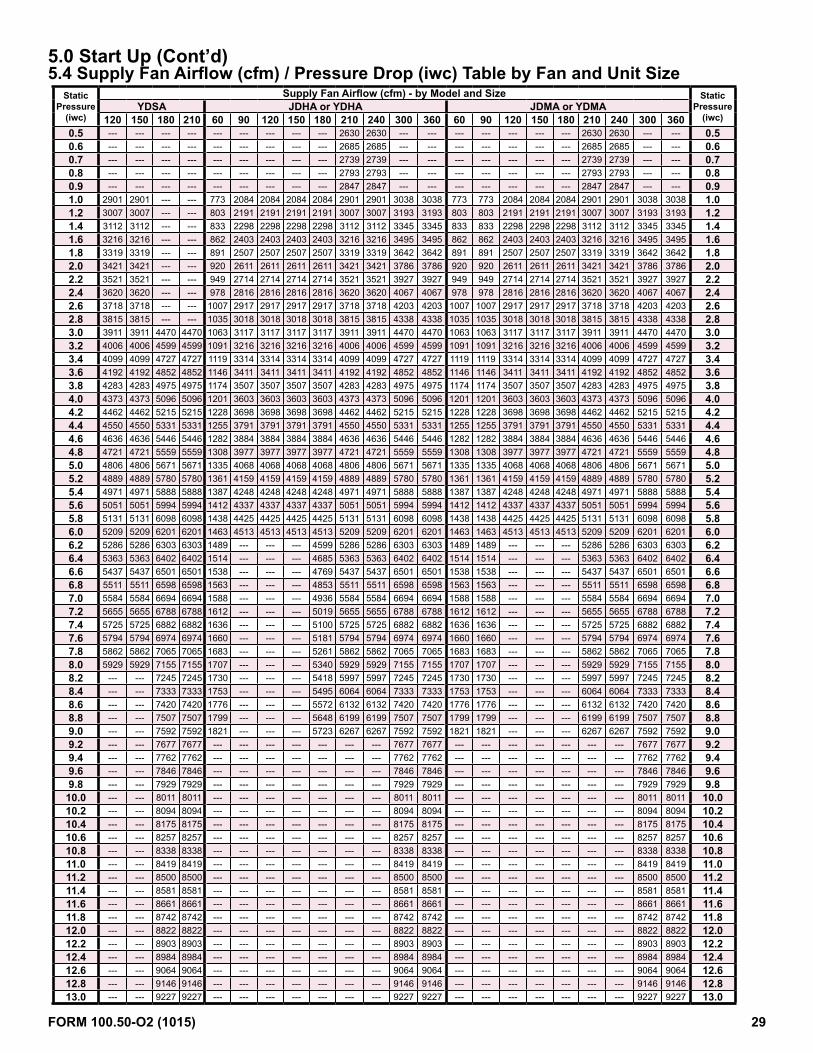
5.0 Start Up (Cont’d)5.4 Supply Fan Airflow (cfm) / Pressure Drop (iwc) Table by Fan and Unit Size
Static Pressure
(iwc)
Supply Fan Airflow (cfm) - by Model and Size Static Pressure
(iwc)YDSA JDHA or YDHA JDMA or YDMA
120 150 180 210 60 90 120 150 180 210 240 300 360 60 90 120 150 180 210 240 300 3600.5 --- --- --- --- --- --- --- --- --- 2630 2630 --- --- --- --- --- --- --- 2630 2630 --- --- 0.50.6 --- --- --- --- --- --- --- --- --- 2685 2685 --- --- --- --- --- --- --- 2685 2685 --- --- 0.60.7 --- --- --- --- --- --- --- --- --- 2739 2739 --- --- --- --- --- --- --- 2739 2739 --- --- 0.70.8 --- --- --- --- --- --- --- --- --- 2793 2793 --- --- --- --- --- --- --- 2793 2793 --- --- 0.80.9 --- --- --- --- --- --- --- --- --- 2847 2847 --- --- --- --- --- --- --- 2847 2847 --- --- 0.91.0 2901 2901 --- --- 773 2084 2084 2084 2084 2901 2901 3038 3038 773 773 2084 2084 2084 2901 2901 3038 3038 1.01.2 3007 3007 --- --- 803 2191 2191 2191 2191 3007 3007 3193 3193 803 803 2191 2191 2191 3007 3007 3193 3193 1.21.4 3112 3112 --- --- 833 2298 2298 2298 2298 3112 3112 3345 3345 833 833 2298 2298 2298 3112 3112 3345 3345 1.41.6 3216 3216 --- --- 862 2403 2403 2403 2403 3216 3216 3495 3495 862 862 2403 2403 2403 3216 3216 3495 3495 1.61.8 3319 3319 --- --- 891 2507 2507 2507 2507 3319 3319 3642 3642 891 891 2507 2507 2507 3319 3319 3642 3642 1.82.0 3421 3421 --- --- 920 2611 2611 2611 2611 3421 3421 3786 3786 920 920 2611 2611 2611 3421 3421 3786 3786 2.02.2 3521 3521 --- --- 949 2714 2714 2714 2714 3521 3521 3927 3927 949 949 2714 2714 2714 3521 3521 3927 3927 2.22.4 3620 3620 --- --- 978 2816 2816 2816 2816 3620 3620 4067 4067 978 978 2816 2816 2816 3620 3620 4067 4067 2.42.6 3718 3718 --- --- 1007 2917 2917 2917 2917 3718 3718 4203 4203 1007 1007 2917 2917 2917 3718 3718 4203 4203 2.62.8 3815 3815 --- --- 1035 3018 3018 3018 3018 3815 3815 4338 4338 1035 1035 3018 3018 3018 3815 3815 4338 4338 2.83.0 3911 3911 4470 4470 1063 3117 3117 3117 3117 3911 3911 4470 4470 1063 1063 3117 3117 3117 3911 3911 4470 4470 3.03.2 4006 4006 4599 4599 1091 3216 3216 3216 3216 4006 4006 4599 4599 1091 1091 3216 3216 3216 4006 4006 4599 4599 3.23.4 4099 4099 4727 4727 1119 3314 3314 3314 3314 4099 4099 4727 4727 1119 1119 3314 3314 3314 4099 4099 4727 4727 3.43.6 4192 4192 4852 4852 1146 3411 3411 3411 3411 4192 4192 4852 4852 1146 1146 3411 3411 3411 4192 4192 4852 4852 3.63.8 4283 4283 4975 4975 1174 3507 3507 3507 3507 4283 4283 4975 4975 1174 1174 3507 3507 3507 4283 4283 4975 4975 3.84.0 4373 4373 5096 5096 1201 3603 3603 3603 3603 4373 4373 5096 5096 1201 1201 3603 3603 3603 4373 4373 5096 5096 4.04.2 4462 4462 5215 5215 1228 3698 3698 3698 3698 4462 4462 5215 5215 1228 1228 3698 3698 3698 4462 4462 5215 5215 4.24.4 4550 4550 5331 5331 1255 3791 3791 3791 3791 4550 4550 5331 5331 1255 1255 3791 3791 3791 4550 4550 5331 5331 4.44.6 4636 4636 5446 5446 1282 3884 3884 3884 3884 4636 4636 5446 5446 1282 1282 3884 3884 3884 4636 4636 5446 5446 4.64.8 4721 4721 5559 5559 1308 3977 3977 3977 3977 4721 4721 5559 5559 1308 1308 3977 3977 3977 4721 4721 5559 5559 4.85.0 4806 4806 5671 5671 1335 4068 4068 4068 4068 4806 4806 5671 5671 1335 1335 4068 4068 4068 4806 4806 5671 5671 5.05.2 4889 4889 5780 5780 1361 4159 4159 4159 4159 4889 4889 5780 5780 1361 1361 4159 4159 4159 4889 4889 5780 5780 5.25.4 4971 4971 5888 5888 1387 4248 4248 4248 4248 4971 4971 5888 5888 1387 1387 4248 4248 4248 4971 4971 5888 5888 5.45.6 5051 5051 5994 5994 1412 4337 4337 4337 4337 5051 5051 5994 5994 1412 1412 4337 4337 4337 5051 5051 5994 5994 5.65.8 5131 5131 6098 6098 1438 4425 4425 4425 4425 5131 5131 6098 6098 1438 1438 4425 4425 4425 5131 5131 6098 6098 5.86.0 5209 5209 6201 6201 1463 4513 4513 4513 4513 5209 5209 6201 6201 1463 1463 4513 4513 4513 5209 5209 6201 6201 6.06.2 5286 5286 6303 6303 1489 --- --- --- 4599 5286 5286 6303 6303 1489 1489 --- --- --- 5286 5286 6303 6303 6.26.4 5363 5363 6402 6402 1514 --- --- --- 4685 5363 5363 6402 6402 1514 1514 --- --- --- 5363 5363 6402 6402 6.46.6 5437 5437 6501 6501 1538 --- --- --- 4769 5437 5437 6501 6501 1538 1538 --- --- --- 5437 5437 6501 6501 6.66.8 5511 5511 6598 6598 1563 --- --- --- 4853 5511 5511 6598 6598 1563 1563 --- --- --- 5511 5511 6598 6598 6.87.0 5584 5584 6694 6694 1588 --- --- --- 4936 5584 5584 6694 6694 1588 1588 --- --- --- 5584 5584 6694 6694 7.07.2 5655 5655 6788 6788 1612 --- --- --- 5019 5655 5655 6788 6788 1612 1612 --- --- --- 5655 5655 6788 6788 7.27.4 5725 5725 6882 6882 1636 --- --- --- 5100 5725 5725 6882 6882 1636 1636 --- --- --- 5725 5725 6882 6882 7.47.6 5794 5794 6974 6974 1660 --- --- --- 5181 5794 5794 6974 6974 1660 1660 --- --- --- 5794 5794 6974 6974 7.67.8 5862 5862 7065 7065 1683 --- --- --- 5261 5862 5862 7065 7065 1683 1683 --- --- --- 5862 5862 7065 7065 7.88.0 5929 5929 7155 7155 1707 --- --- --- 5340 5929 5929 7155 7155 1707 1707 --- --- --- 5929 5929 7155 7155 8.08.2 --- --- 7245 7245 1730 --- --- --- 5418 5997 5997 7245 7245 1730 1730 --- --- --- 5997 5997 7245 7245 8.28.4 --- --- 7333 7333 1753 --- --- --- 5495 6064 6064 7333 7333 1753 1753 --- --- --- 6064 6064 7333 7333 8.48.6 --- --- 7420 7420 1776 --- --- --- 5572 6132 6132 7420 7420 1776 1776 --- --- --- 6132 6132 7420 7420 8.68.8 --- --- 7507 7507 1799 --- --- --- 5648 6199 6199 7507 7507 1799 1799 --- --- --- 6199 6199 7507 7507 8.89.0 --- --- 7592 7592 1821 --- --- --- 5723 6267 6267 7592 7592 1821 1821 --- --- --- 6267 6267 7592 7592 9.09.2 --- --- 7677 7677 --- --- --- --- --- --- --- 7677 7677 --- --- --- --- --- --- --- 7677 7677 9.29.4 --- --- 7762 7762 --- --- --- --- --- --- --- 7762 7762 --- --- --- --- --- --- --- 7762 7762 9.49.6 --- --- 7846 7846 --- --- --- --- --- --- --- 7846 7846 --- --- --- --- --- --- --- 7846 7846 9.69.8 --- --- 7929 7929 --- --- --- --- --- --- --- 7929 7929 --- --- --- --- --- --- --- 7929 7929 9.810.0 --- --- 8011 8011 --- --- --- --- --- --- --- 8011 8011 --- --- --- --- --- --- --- 8011 8011 10.010.2 --- --- 8094 8094 --- --- --- --- --- --- --- 8094 8094 --- --- --- --- --- --- --- 8094 8094 10.210.4 --- --- 8175 8175 --- --- --- --- --- --- --- 8175 8175 --- --- --- --- --- --- --- 8175 8175 10.410.6 --- --- 8257 8257 --- --- --- --- --- --- --- 8257 8257 --- --- --- --- --- --- --- 8257 8257 10.610.8 --- --- 8338 8338 --- --- --- --- --- --- --- 8338 8338 --- --- --- --- --- --- --- 8338 8338 10.811.0 --- --- 8419 8419 --- --- --- --- --- --- --- 8419 8419 --- --- --- --- --- --- --- 8419 8419 11.011.2 --- --- 8500 8500 --- --- --- --- --- --- --- 8500 8500 --- --- --- --- --- --- --- 8500 8500 11.211.4 --- --- 8581 8581 --- --- --- --- --- --- --- 8581 8581 --- --- --- --- --- --- --- 8581 8581 11.411.6 --- --- 8661 8661 --- --- --- --- --- --- --- 8661 8661 --- --- --- --- --- --- --- 8661 8661 11.611.8 --- --- 8742 8742 --- --- --- --- --- --- --- 8742 8742 --- --- --- --- --- --- --- 8742 8742 11.812.0 --- --- 8822 8822 --- --- --- --- --- --- --- 8822 8822 --- --- --- --- --- --- --- 8822 8822 12.012.2 --- --- 8903 8903 --- --- --- --- --- --- --- 8903 8903 --- --- --- --- --- --- --- 8903 8903 12.212.4 --- --- 8984 8984 --- --- --- --- --- --- --- 8984 8984 --- --- --- --- --- --- --- 8984 8984 12.412.6 --- --- 9064 9064 --- --- --- --- --- --- --- 9064 9064 --- --- --- --- --- --- --- 9064 9064 12.612.8 --- --- 9146 9146 --- --- --- --- --- --- --- 9146 9146 --- --- --- --- --- --- --- 9146 9146 12.813.0 --- --- 9227 9227 --- --- --- --- --- --- --- 9227 9227 --- --- --- --- --- --- --- 9227 9227 13.0
FORM 100.50-O2 (1015) 29

5.5 Power Exhaust PE4 Airflow (cfm) / Pressure Drop (iwc) Table by Fan and Unit Size
Static Pressure
(iwc)
Power Exhaust PE4 Airflow (cfm) - by Model and Size Static Pressure
(iwc)YDSA JDHA or YDHA JDMA or YDMA
120 150 180 210 60 90 120 150 180 210 240 300 360 60 90 120 150 180 210 240 300 3600.2 595 595 378 378 1051 1051 1051 1051 595 595 595 378 378 1051 1051 1051 1051 595 595 595 378 378 0.20.4 830 830 553 553 1154 1154 1154 1154 830 830 830 553 553 1154 1154 1154 1154 830 830 830 553 553 0.40.6 1051 1051 723 723 1255 1255 1255 1255 1051 1051 1051 723 723 1255 1255 1255 1255 1051 1051 1051 723 723 0.60.8 1257 1257 886 886 1354 1354 1354 1354 1257 1257 1257 886 886 1354 1354 1354 1354 1257 1257 1257 886 886 0.81.0 1449 1449 1043 1043 1451 1451 1451 1451 1449 1449 1449 1043 1043 1451 1451 1451 1451 1449 1449 1449 1043 1043 1.01.2 1629 1629 1195 1195 1546 1546 1546 1546 1629 1629 1629 1195 1195 1546 1546 1546 1546 1629 1629 1629 1195 1195 1.21.4 1795 1795 1341 1341 1639 1639 1639 1639 1795 1795 1795 1341 1341 1639 1639 1639 1639 1795 1795 1795 1341 1341 1.41.6 1950 1950 1481 1481 1730 1730 1730 1730 1950 1950 1950 1481 1481 1730 1730 1730 1730 1950 1950 1950 1481 1481 1.61.8 2094 2094 1616 1616 1819 1819 1819 1819 2094 2094 2094 1616 1616 1819 1819 1819 1819 2094 2094 2094 1616 1616 1.82.0 2227 2227 1746 1746 1905 1905 1905 1905 2227 2227 2227 1746 1746 1905 1905 1905 1905 2227 2227 2227 1746 1746 2.02.2 2349 2349 1872 1872 1990 1990 1990 1990 2349 2349 2349 1872 1872 1990 1990 1990 1990 2349 2349 2349 1872 1872 2.22.4 2463 2463 1992 1992 2072 2072 2072 2072 2463 2463 2463 1992 1992 2072 2072 2072 2072 2463 2463 2463 1992 1992 2.42.6 2567 2567 2108 2108 2153 2153 2153 2153 2567 2567 2567 2108 2108 2153 2153 2153 2153 2567 2567 2567 2108 2108 2.62.8 2663 2663 2219 2219 2231 2231 2231 2231 2663 2663 2663 2219 2219 2231 2231 2231 2231 2663 2663 2663 2219 2219 2.83.0 2752 2752 2327 2327 2307 2307 2307 2307 2752 2752 2752 2327 2327 2307 2307 2307 2307 2752 2752 2752 2327 2327 3.03.2 2834 2834 2430 2430 2382 2382 2382 2382 2834 2834 2834 2430 2430 2382 2382 2382 2382 2834 2834 2834 2430 2430 3.23.4 2909 2909 2530 2530 2454 2454 2454 2454 2909 2909 2909 2530 2530 2454 2454 2454 2454 2909 2909 2909 2530 2530 3.43.6 2978 2978 2625 2625 2524 2524 2524 2524 2978 2978 2978 2625 2625 2524 2524 2524 2524 2978 2978 2978 2625 2625 3.63.8 3043 3043 2718 2718 2592 2592 2592 2592 3043 3043 3043 2718 2718 2592 2592 2592 2592 3043 3043 3043 2718 2718 3.84.0 3103 3103 2807 2807 2658 2658 2658 2658 3103 3103 3103 2807 2807 2658 2658 2658 2658 3103 3103 3103 2807 2807 4.04.2 3159 3159 2892 2892 2722 2722 2722 2722 3159 3159 3159 2892 2892 2722 2722 2722 2722 3159 3159 3159 2892 2892 4.24.4 3211 3211 2975 2975 2784 2784 2784 2784 3211 3211 3211 2975 2975 2784 2784 2784 2784 3211 3211 3211 2975 2975 4.44.6 3261 3261 3055 3055 2843 2843 2843 2843 3261 3261 3261 3055 3055 2843 2843 2843 2843 3261 3261 3261 3055 3055 4.64.8 3309 3309 3133 3133 2901 2901 2901 2901 3309 3309 3309 3133 3133 2901 2901 2901 2901 3309 3309 3309 3133 3133 4.85.0 3356 3356 3208 3208 2957 2957 2957 2957 3356 3356 3356 3208 3208 2957 2957 2957 2957 3356 3356 3356 3208 3208 5.05.2 3401 3401 3281 3281 3010 3010 3010 3010 3401 3401 3401 3281 3281 3010 3010 3010 3010 3401 3401 3401 3281 3281 5.25.4 3447 3447 3351 3351 3062 3062 3062 3062 3447 3447 3447 3351 3351 3062 3062 3062 3062 3447 3447 3447 3351 3351 5.45.6 3493 3493 3420 3420 3111 3111 3111 3111 3493 3493 3493 3420 3420 3111 3111 3111 3111 3493 3493 3493 3420 3420 5.65.8 3539 3539 3487 3487 3158 3158 3158 3158 3539 3539 3539 3487 3487 3158 3158 3158 3158 3539 3539 3539 3487 3487 5.86.0 3588 3588 3553 3553 3204 3204 3204 3204 3588 3588 3588 3553 3553 3204 3204 3204 3204 3588 3588 3588 3553 3553 6.06.2 3639 3639 3617 3617 3247 3247 3247 3247 3639 3639 3639 3617 3617 3247 3247 3247 3247 3639 3639 3639 3617 3617 6.26.4 3692 3692 3680 3680 3288 3288 3288 3288 3692 3692 3692 3680 3680 3288 3288 3288 3288 3692 3692 3692 3680 3680 6.46.6 3749 3749 3742 3742 3327 3327 3327 3327 3749 3749 3749 3742 3742 3327 3327 3327 3327 3749 3749 3749 3742 3742 6.66.8 3811 3811 3803 3803 3364 3364 3364 3364 3811 3811 3811 3803 3803 3364 3364 3364 3364 3811 3811 3811 3803 3803 6.87.0 3877 3877 3863 3863 3399 3399 3399 3399 3877 3877 3877 3863 3863 3399 3399 3399 3399 3877 3877 3877 3863 3863 7.07.2 3948 3948 3923 3923 3432 3432 3432 3432 3948 3948 3948 3923 3923 3432 3432 3432 3432 3948 3948 3948 3923 3923 7.27.4 4025 4025 3983 3983 3463 3463 3463 3463 4025 4025 4025 3983 3983 3463 3463 3463 3463 4025 4025 4025 3983 3983 7.47.6 4109 4109 4043 4043 3491 3491 3491 3491 4109 4109 4109 4043 4043 3491 3491 3491 3491 4109 4109 4109 4043 4043 7.67.8 4200 4200 4102 4102 3518 3518 3518 3518 4200 4200 4200 4102 4102 3518 3518 3518 3518 4200 4200 4200 4102 4102 7.88.0 4298 4298 4162 4162 3542 3542 3542 3542 4298 4298 4298 4162 4162 3542 3542 3542 3542 4298 4298 4298 4162 4162 8.08.2 --- --- 4222 4222 --- --- --- --- --- --- --- 4222 4222 --- --- --- --- --- --- --- 4222 4222 8.28.4 --- --- 4283 4283 --- --- --- --- --- --- --- 4283 4283 --- --- --- --- --- --- --- 4283 4283 8.48.6 --- --- 4344 4344 --- --- --- --- --- --- --- 4344 4344 --- --- --- --- --- --- --- 4344 4344 8.68.8 --- --- 4407 4407 --- --- --- --- --- --- --- 4407 4407 --- --- --- --- --- --- --- 4407 4407 8.89.0 --- --- 4470 4470 --- --- --- --- --- --- --- 4470 4470 --- --- --- --- --- --- --- 4470 4470 9.09.2 --- --- --- --- --- --- --- --- --- --- --- --- --- --- --- --- --- --- --- --- --- --- 9.29.4 --- --- --- --- --- --- --- --- --- --- --- --- --- --- --- --- --- --- --- --- --- --- 9.49.6 --- --- --- --- --- --- --- --- --- --- --- --- --- --- --- --- --- --- --- --- --- --- 9.69.8 --- --- --- --- --- --- --- --- --- --- --- --- --- --- --- --- --- --- --- --- --- --- 9.810.0 --- --- --- --- --- --- --- --- --- --- --- --- --- --- --- --- --- --- --- --- --- --- 10.010.2 --- --- --- --- --- --- --- --- --- --- --- --- --- --- --- --- --- --- --- --- --- --- 10.210.4 --- --- --- --- --- --- --- --- --- --- --- --- --- --- --- --- --- --- --- --- --- --- 10.410.6 --- --- --- --- --- --- --- --- --- --- --- --- --- --- --- --- --- --- --- --- --- --- 10.610.8 --- --- --- --- --- --- --- --- --- --- --- --- --- --- --- --- --- --- --- --- --- --- 10.811.0 --- --- --- --- --- --- --- --- --- --- --- --- --- --- --- --- --- --- --- --- --- --- 11.0
FORM 100.50-O2 (1015) 30
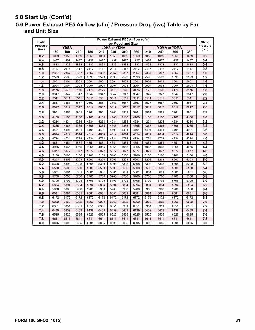
5.0 Start Up (Cont’d)5.6 Power Exhauxt PE5 Airflow (cfm) / Pressure Drop (iwc) Table by Fan
and Unit Size
Static Pressure
(iwc)
Power Exhaust PE5 Airflow (cfm) by Model and Size Static
Pressure (iwc)YDSA JDHA or YDHA YDMA or YDMA
150 180 210 180 210 240 300 360 210 240 300 3600.2 1059 1059 1059 1059 1059 1059 1059 1059 1059 1059 1059 1059 0.20.4 1497 1497 1497 1497 1497 1497 1497 1497 1497 1497 1497 1497 0.40.6 1833 1833 1833 1833 1833 1833 1833 1833 1833 1833 1833 1833 0.60.8 2117 2117 2117 2117 2117 2117 2117 2117 2117 2117 2117 2117 0.81.0 2367 2367 2367 2367 2367 2367 2367 2367 2367 2367 2367 2367 1.01.2 2593 2593 2593 2593 2593 2593 2593 2593 2593 2593 2593 2593 1.21.4 2801 2801 2801 2801 2801 2801 2801 2801 2801 2801 2801 2801 1.41.6 2994 2994 2994 2994 2994 2994 2994 2994 2994 2994 2994 2994 1.61.8 3176 3176 3176 3176 3176 3176 3176 3176 3176 3176 3176 3176 1.82.0 3347 3347 3347 3347 3347 3347 3347 3347 3347 3347 3347 3347 2.02.2 3511 3511 3511 3511 3511 3511 3511 3511 3511 3511 3511 3511 2.22.4 3667 3667 3667 3667 3667 3667 3667 3667 3677 3667 3667 3667 2.42.6 3817 3817 3817 3817 3817 3817 3817 3817 3817 3817 3817 3817 2.62.8 3961 3961 3961 3961 3961 3961 3961 3961 3961 3961 3961 3961 2.83.0 4100 4100 4100 4100 4100 4100 4100 4100 4100 4100 4100 4100 3.03.2 4234 4234 4234 4234 4234 4234 4234 4234 4234 4234 4234 4234 3.23.4 4365 4365 4365 4365 4365 4365 4365 4365 4365 4365 4365 4365 3.43.6 4491 4491 4491 4491 4491 4491 4491 4491 4491 4491 4491 4491 3.63.8 4614 4614 4614 4614 4614 4614 4614 4614 4614 4614 4614 4614 3.84.0 4734 4734 4734 4734 4734 4734 4734 4734 4734 4734 4734 4734 4.04.2 4851 4851 4851 4851 4851 4851 4851 4851 4851 4851 4851 4851 4.24.4 4965 4965 4965 4965 4965 4965 4965 4965 4965 4965 4965 4965 4.44.6 5077 5077 5077 5077 5077 5077 5077 5077 5077 5077 5077 5077 4.64.8 5186 5186 5186 5186 5186 5186 5186 5186 5186 5186 5186 5186 4.85.0 5293 5293 5293 5293 5293 5293 5293 5293 5293 5293 5293 5293 5.05.2 5398 5398 5398 5398 5398 5398 5398 5398 5398 5398 5398 5398 5.25.4 5500 5500 5500 5500 5500 5500 5500 5500 5500 5500 5500 5500 5.45.6 5601 5601 5601 5601 5601 5601 5601 5601 5601 5601 5601 5601 5.65.8 5700 5700 5700 5700 5700 5700 5700 5700 5700 5700 5700 5700 5.86.0 5798 5798 5798 5798 5798 5798 5798 5798 5798 5798 5798 5798 6.06.2 5894 5894 5894 5894 5894 5894 5894 5894 5894 5894 5894 5894 6.26.4 5988 5988 5988 5988 5988 5988 5988 5988 5988 5988 5988 5988 6.46.6 6081 6081 6081 6081 6081 6081 6081 6081 6081 6081 6081 6081 6.66.8 6172 6172 6172 6172 6172 6172 6172 6172 6172 6172 6172 6172 6.87.0 6262 6262 6262 6262 6262 6262 6262 6262 6262 6262 6262 6262 7.07.2 6351 6351 6351 6351 6351 6351 6351 6351 6351 6351 6351 6351 7.27.4 6439 6439 6439 6439 6439 6439 6439 6439 6439 6439 6439 6439 7.47.6 6525 6525 6525 6525 6525 6525 6525 6525 6525 6525 6525 6525 7.67.8 6611 6611 6611 6611 6611 6611 6611 6611 6611 6611 6611 6611 7.88.0 6695 6695 6695 6695 6695 6695 6695 6695 6695 6695 6695 6695 8.0
FORM 100.50-O2 (1015) 31

5.7 PE6 Airflow (cfm) / Pressure Drop (iwc) Tables by Fan and Unit Size
Static Pressure
(iwc)
Power Exhaust PE6 Airflow (cfm) by Model and Size Static
Pressure (iwc)JDHA or YDHA YDMA or YDMA
300 360 300 3600.2 1236 1236 1236 1236 0.20.4 1747 1747 1747 1747 0.40.6 2139 2139 2139 2139 0.60.8 2470 2470 2470 2470 0.81.0 2762 2762 2762 2762 1.01.2 3025 3025 3025 3025 1.21.4 3268 3268 3268 3268 1.41.6 3493 3493 3493 3493 1.61.8 3705 3705 3705 3705 1.82.0 3905 3905 3905 3905 2.02.2 4096 4096 4096 4096 2.22.4 4278 4278 4278 4278 2.42.6 4453 4453 4453 4453 2.62.8 4621 4621 4621 4621 2.83.0 4783 4783 4783 4783 3.03.2 4940 4940 4940 4940 3.23.4 5093 5093 5093 5093 3.43.6 5240 5240 5240 5240 3.63.8 5383 5383 5383 5383 3.84.0 5523 5523 5523 5523 4.04.2 5660 5660 5660 5660 4.24.4 5793 5793 5793 5793 4.44.6 5923 5923 5923 5923 4.64.8 6050 6050 6050 6050 4.85.0 6175 6175 6175 6175 5.05.2 6298 6298 6298 6298 5.25.4 6417 6417 6417 6417 5.45.6 6535 6535 6535 6535 5.65.8 6650 6650 6650 6650 5.86.0 6764 6764 6764 6764 6.06.2 6876 6876 6876 6876 6.26.4 6986 6986 6986 6986 6.46.6 7095 7095 7095 7095 6.66.8 7201 7201 7201 7201 6.87.0 7306 7306 7306 7306 7.07.2 7410 7410 7410 7410 7.27.4 7512 7512 7512 7512 7.47.6 7613 7613 7613 7613 7.67.8 7713 7713 7713 7713 7.88.0 7811 7811 7811 7811 8.0
FORM 100.50-O2 (1015) 32

6.0 Controller History Log
Hardware Inputs, Outputs, and selected setpoints listed in the Setpoint History Log Table will be sampled in five-minute intervals. The history log will roll over when the data fills the available log space.To access the controller history log:
Press the alarm and enter key simultane-ously for 5 seconds and the system bios screen will appear. Use the down key to select LOG DATA and press enter.
The #1 DISPLAY LOG DATA screen will appear. Press the enter key to advance.
The #2 DISPLAY LOG DATA screen will appear. Press the enter key to advance.
The #3 record selection screen will appear. Use the up and down keys to select the desired record by date and time and press enter to view the data.
Use the up and down keys to scroll through the history log point values for that date and time record.
Press the escape key in succession to return to the previous screens.
FORM 100.50-O2 (1015) 33

7.0 Controller Display Menus
Main Screen M.x Main Screen M.1 or M.2 will be displayed depending upon unit configuration (Monitor Only)Name Description Default Unit Min Max
Spc_Temp: Space Temp - Current Space Temperature Deg F
SpcTempSP: Space Temp SP - Base space temp setpoint value from the space thermostat or controller display adjustment 72 Deg F 65 85
DA_Temp: Discharge Air Temp - Current Discharge Air Temperature Deg FDA_SP: Discharge Air Temp Active SP - Active Discharge Air Temperature Setpoint Deg F
State: Current Unit State - 2=AUTO 3=COOL 4=HEAT 5=OFF OFF 2 5Mode: Current Unit Mode - Occ or Unocc
Fan: Current Supply Fan Commanded Speed %
Main Screen M.x Main Screen M.3 or M.4 will be displayed depending upon unit configuration (Monitor Only)Name Description Default Unit Min Max
Spc_Humidity: Space Humidity - Current Space Humidity %rHSpcHumSP: Space Humidity SP - Current Space Humidity Setpoint 55 %rH 35 75
Temperature: Current Outside Air Temp Deg FHumidity: Current Outside Air Humidity %rH
Dew Point: Current Outside Air Dew Point Deg F
Main Screen M.x Main Screen M.5, M.6, M.7 or M.8 will be displayed depending upon unit configuration (Monitor Only)Name Description Default Unit Min Max
Spc_Clg_Md: Space Cooling Mode - Unit controls applicable cooling stages to maintain the DA_SpcClg_SP Off On
Spc_Dehum_Md: Space Dehum Mode - Unit controls reheat compressor to maintain the DA_Dh_SP and applicable cooling stages to maintain the CC_DA_SP Off On
Spc_Htg_Md: Space Heating Mode - Unit controls applicable heating stages to maintain the DA_SpcHtg_SP Off On
Spc_HtgClg_Md: Space Heating Cooling Mode - Unit controls applicable heating stages to maintain the DA_SpcHtCl_SP (Auto Heating Only) Off On
NA_Clg_Md: Neutral Air Cooling Mode - Unit controls applicable cooling stages to maintain the DA_NAClg_SP Off On
NA_Dehum_Md: Neutral Air Dehum Mode - Unit controls reheat compressor to maintain the DA_Dh_SP and applicable cooling stages to maintain the CC_DA_SP Off On
NA_Htg_Md: Neutral Air Heating Mode - Unit controls applicable heating stages to maintain the DA_NAHtg_SP Off On
Main MenuA. Quick Setpoints Quick Setpoints MenuQuick Setpoints A.1 Quick Setpoints Screen A.1
Name Description Default Unit Min MaxState_Sel: State Select 2=AUTO 3=COOL 4=HEAT 5=OFF - Sets Unit State 5 2 5
OccMode_Sel: Occ Mode Select 0= Schedule 1= Digital Input 2= BMS - Sets desired unit occupancy method 1 0 2
OAChgOv_SP: OA Change Over SP - OA temp setpoint used to enable heating and cooling when the unit is in the auto state 65 Deg F 45 80
OAChgOvDiff: OA Change Over SP Differential - Differential for the OAChgOv_SP 5 Deg F 05 10
OAChgOvDel: OA Change Over Delay Time - Delay period required to switch between heating and cooling when the unit is in the auto state 15 min 5 30
TempOcc: Temporary Occupied Status from Space Thermostat - Indexed on when the thermostat fan button is pressed Off Off On
TempOcc_Time: Temporary Occupied Time Duration - Sets time duration for Temporary Occupancy 240 min 0 480
Quick Setpoints A.2 Quick Setpoints Screen A.2 Will be displayed when unit is configured for Space ControlName Description Default Unit Min Max
Spc_Temp: Space Temp - Current Space Temperature Deg F
SpcTempSP: Space Temp SP - Base space temp setpoint value from the space thermostat or controller display adjustment 72 Deg F 65 85
SpcHtgSp: Space Heating SP - Value is equal to the SpcTempSP minus the SpcHtgDB (Also used as control SP for Spc_HtgClg_Md) 71 Deg F
SpcClgSp: Space Cooling SP - Value is equal to the SpcTempSP plus the SpcClgDB 73 Deg F
SpcHtgDB: Space Heating Dead Band - Sets value subtracted from the SpcTempSP for the SpcEffHtgSP definition 1 Deg F 0 5
SpcClgDB: Space Cooling Dead Band - Sets value added to the SpcTempSP for the SpcEffClgSP definition 1 Deg F 0 5
Option D21 Control Program - User and Service Menu Structure
FORM 100.50-O2 (1015) 34

A Quick Setpoints Quick Setpoints Menu (Cont’d)Quick Setpoints A.3 Quick Setpoints Screen A.3 Will be displayed when unit is configured for Space Control
Name Description Default Unit Min MaxSpcEffClgSP: Space Effective Cooling SP - Defined by the SpcClgDB and the SpcClgUnoOs setpoints Deg F
SpcClgOnDiff: Space Cooling On Differential - Sets the differential required above the SpcEffClgSP for the space cooling call to turn on 4 Deg F 05 10
SpcClgOffDiff: Space Cooling Off Differential - Sets the differential required below the SpcEffClgSP for the space cooling call to turn off 1 Deg F 05 10
SpcClgUnoOs: Space Cooling Unoccupied Offset - Sets the value added to the SpcTempSP when in the unoccupied mode for the SpcEffClgSP definition 5 Deg F 0 15
DA_SpcClg_SP: Discharge Air Temp Space Cooling SP - Sets the discharge setpoint used when in Space Cooling Mode 55 Deg F 50 100
Quick Setpoints A.4 Quick Setpoints Screen A.4 Will be displayed when unit is configured for Space ControlName Description Default Unit Min Max
SpcEffHtgSP: Space Effective Heating SP - Defined by the SpcHtgDB and the SpcHtgUnoOs setpoints Deg F
SpcHtgOnDiff: Space Heating On Differential - Sets the differential required below the SpcEffHtgSP for the space heating call to turn on 4 Deg F 05 10
SpcHtgOffDiff: Space Heating Off Differential - Sets the differential required above the SpcEffHtgSP for the space heating call to turn off 1 Deg F 05 10
SpcHtgUnoOs: Space Heating Unoccupied Offset - Sets the value subtracted from the SpcTempSP when in the unoccupied mode for the SpcEffHtgSP definition 5 Deg F 0 15
DA_SpcHtg_SP: Discharge Air Temp Space Heating SP - Sets the discharge setpoint used when in Space Heating Mode 90 Deg F 50 140
Quick Setpoints A.5 Quick Setpoints Screen A.5 Will be displayed when unit is configured for Space ControlName Description Default Unit Min Max
SpcHtgSp: Space Heating SP - Value is equal to the SpcTempSP minus the SpcHtgDB (Also used as control SP for Spc_HtgClg_Md) 71 Deg F
SpcHCOnDiff: Space Heating Cooling On Differential - Sets the differential required above the SpcTempSP for the space cooling call to turn on (Auto Heating Only) 5 Deg F 05 10
SpcHCOffDiff: Space Heating Cooling Off Differential - Sets the differential required below the SpcTempSP for the space cooling call to turn off (Auto Heating Only) 1 Deg F 05 10
DA_SpcHtCl_SP: Discharge Air Temp Space Heat Mode Cooling SP - Sets the discharge air setpoint used when in Space Heat Cooling Mode (Auto Heating Only) 55 Deg F 50 100
Quick Setpoints A.6 Quick Setpoints Screen A.6 Will be displayed when unit is configured for Space Control and DehumidificationName Description Default Unit Min Max
Spc_Humidity: Space Humidity - Current Space Humidity %rHSpcHumSP: Space Humidity SP - Sets the Space Humidity Setpoint 55 %rH 35 75
SpcDhOnDiff: Space Dehum On Differential - Sets the differential required above the SpcHumSP for the space dehum call to turn on 10 %rH 1 10
SpcDhOffDiff: Space Dehum Off Differential - Sets the differential required below the SpcHumSP for the space dehum call to turn off 5 %rH 1 10
Quick Setpoints A.7 Quick Setpoints Screen A.7Name Description Default Unit Min Max
DA_NAClg_SP: Discharge Air Temp Neutral Cooling SP - Sets the discharge setpoint used when in Neutral Air Cooling Mode 70 Deg F 50 100
DA_NAHSPSel: Neutral DA Heating SP Select - Used to select desired discharge setpoint for Neutral Air Heating Mode Single Setpoint or Reset Setpoint Setpt Setpt Reset
DA_NAHtg_SP: Discharge Air Temp Neutral Heating SP - Sets the discharge setpoint used when in Neutral Air Heating Mode 70 Deg F 50 140
DA_NAHRst_SP: Discharge Air Temp Neutral Heat Reset SP - Display of optional calculated reset schedule setpoint used when in Neutral Air Heating Mode Deg F 50 140
Quick Setpoints A.8 Quick Setpoints Screen A.8
Name Description Default Unit Min MaxOA_Temp: Current Outside Air Temp Deg F
DA_NAHRst_SP: Discharge Air Temp Neutral Heat Reset SP - Display of optional calculated reset schedule setpoint used when in Neutral Air Heating Mode Deg F 50 140
NAHRDAMax: Neutral Air Heat DA SP Reset DA Max - Sets the maximum neutral air heating discharge air temp reset setpoint 75 Deg F 50 140
7.0 Controller Display Menus (cont’d)
FORM 100.50-O2 (1015) 35

Quick Setpoints A.8 Quick Setpoints Screen A.8 (Cont’d)Name Description Default Unit Min Max
NAHRDAMin: Neutral Air Heat DA SP Reset DA Min - Sets the minimum neutral air heating discharge air temp reset setpoint 65 Deg F 50 140
NAHROAMax: Neutral Air Heat DA SP Reset OA Max - Sets the maximum neutral air heating outside air temp reset setpoint 65 Deg F 0 100
NAHROAMin: Neutral Air Heat DA SP Reset OA Min - Sets the minimum neutral air heating outside air temp reset setpoint 30 Deg F 0 100
Quick Setpoints A.9 Quick Setpoints Screen A.9 Will Be displayed when the unit is configured for DehumidificationName Description Default Unit Min Max
DhOADP_SP: Sets the Dehum OA Dew Point SP - Used to allow Neutral Air Dehumidification Mode when the OA dew point is greater than SP 58 Deg F 50 100
DhOADP_Diff: Dehum OA Dew Point SP Differential - Sets the differential for the DhOADP_SP 2 Deg F 05 10
Quick Setpoints A.10 Quick Setpoints Screen A.10 Will Be displayed when the unit is configured for Building Pressure ControlName Description Default Unit Min Max
Pressure Control Factory Selection: BuildingControlled Device Factory Selection: Supply Fan - Exhaust Fan - Dampers
Bldg_Pressure Building Static PressureSetpoint: Building Static Pressure SP 0.1 iwc -0.5 0.5
Quick Setpoints A.11 Quick Setpoints Screen A.11 Will Be displayed when the unit is configured for Duct Pressure ControlName Description Default Unit Min Max
Pressure Control Factory Selection: DuctControlled Device Factory Selection: Supply Fan
Duct_Pressure Duct Static PressureSetpoint: Duct Static Pressure SP 0.5 iwc 0 2.5
Main MenuB. Schedule Schedule MenuSchedule B.1 Schedule Screen B.1
Name Description Default Unit Min MaxDate: Sets the current month day and year - Default Value: Factory DateHour: Sets the current time - Default Value: Factory Time
Schedule B.2 Schedule Screen B.2Name Description Default Unit Min MaxDST: Set to enable DST - Default Value: Enable
Transition Time: Sets Transition Time - Default Value: 60 minStart: Sets Start day , month and time - Default Value: Last Sunday in March at 2:00End: Sets End day , month and time - Default Value: Last Sunday in October at 3:00
Schedule B.3 Schedule Screen B.3 will be displayed if unit OccMode_Sel is set to ScheduleName Description Default Unit Min Max
Schedule #: Modifiable Field used to advance through 10 available Weekly SchedulesTime On: Sets the desired On time for selected Schedule #Time Off: Sets the desired Off time for selected Schedule #
Days Enabled: Sets the desired days of the week for the selected Schedule #
Schedule B.4 Schedule Screen B.4 will be displayed if unit OccMode_Sel is set to ScheduleName Description Default Unit Min Max
1: Sets the desired Holiday Range 1: For Extended Unoccupied Mode 0/0 - 0/02: Sets the desired Holiday Range 2: For Extended Unoccupied Mode 0/0 - 0/03: Sets the desired Holiday Range 3: For Extended Unoccupied Mode 0/0 - 0/04: Sets the desired Holiday Range 4: For Extended Unoccupied Mode 0/0 - 0/0
Schedule B.5 Schedule Screen B.5 will be displayed if unit OccMode_Sel is set to ScheduleName Description Default Unit Min Max
5: Sets the desired Holiday Range 5: For Extended Unoccupied Mode 0/0 - 0/06: Sets the desired Holiday Range 6: For Extended Unoccupied Mode 0/0 - 0/07: Sets the desired Holiday Range 7: For Extended Unoccupied Mode 0/0 - 0/08: Sets the desired Holiday Range 8: For Extended Unoccupied Mode 0/0 - 0/0
FORM 100.50-O2 (1015) 36

Schedule B.6 Schedule Screen B.6 will be displayed if unit OccMode_Sel is set to ScheduleName Description Default Unit Min Max
9: Sets the desired Holiday Range 9: For Extended Unoccupied Mode 0/0 - 0/010: Sets the desired Holiday Range 10: For Extended Unoccupied Mode 0/0 - 0/011: Sets the desired Holiday Range 11: For Extended Unoccupied Mode 0/0 - 0/012: Sets the desired Holiday Range 12: For Extended Unoccupied Mode 0/0 - 0/0
Schedule B.7 Schedule Screen B.7 will be displayed if unit OccMode_Sel is set to ScheduleName Description Default Unit Min Max
13: Sets the desired Holiday Range 13: For Extended Unoccupied Mode 0/0 - 0/014: Sets the desired Holiday Range 14: For Extended Unoccupied Mode 0/0 - 0/015: Sets the desired Holiday Range 15: For Extended Unoccupied Mode 0/0 - 0/016: Sets the desired Holiday Range 16: For Extended Unoccupied Mode 0/0 - 0/0
Main MenuC. Points List Points List Menu - Applicable screens and content will be displayed depending upon unit configuration
See Hardware Point Table on page 2 for Complete List of IO Points and Serial Communication Connections
Points List C.1 Points List Screen C.1Applicable Analog Outputs for Unit Configuration
Points List C.2 Points List Screen C.2Applicable Relay Outputs for Unit Configuration
Points List C.3 Points List Screen C.3Applicable Relay Outputs for Unit Configuration
Points List C.4 Points List Screen C.4Applicable Relay Outputs for Unit Configuration
Points List C.5 Points List Screen C.5Applicable Analog Inputs for Unit Configuration
Points List C.6 Points List Screen C.6Applicable Analog Inputs for Unit Configuration
Point Lists C.7 thru C.12
Points List Screens C.7 thru C.12 contain the temp & humidity values for the optional space sensors 1 thru 6.
Points List C.13 Point List Screen C.13 contains the temp & humidity values for the optional return air temp probe
Points List C.14 Point List Screen C.14 contains the temp & humidity values for the optional exhaust air temp probe
Points List C.15 Points List Screen C.15 contains the current status information for the EBM exhaust fan.
Points List C.16 Points List Screen C.16Applicable Digital Inputs for Unit Configuration
Points List C.17 Points List Screen C.17Applicable Digital Inputs for Unit Configuration
Points List C.18 Points List Screen C.18Applicable Digital Inputs for Unit Configuration
Main Menu
D. Alarms Alarms Menu - Active Alarms are displayed with the option of entering the Alarm LoggerSee Alarm Management Section paragraph 4.2 of this document for detailed information on Active and Logged alarms
Main MenuE. Service Service Menu
a. Test Mode Test Mode Menu
Test Mode E.a.1 Test Mode Screen E.a.1Name Description Default Unit Min Max
Enable: Modifiable Field Used to enable the Test ModeTime Out: Modifiable Field Used to adjust the test mode time duration 120 min 0 240
Countdown: Current status of the time remaining for Test Mode if active min / s
7.0 Controller Display Menus (cont’d)
FORM 100.50-O2 (1015) 37

Test Mode E.a.2 Test Mode Screen E.a.2Name Description Default Unit Min Max
Damper: Automatically Commanded Percentage Output to unit Damper(s) 100 % 100 100Supply: Automatically Commanded Supply Fan Start Output
Supply Fan Speed Output Modifiable Field used to test unit Supply Fan VFD and set Air Balance fan speed adjustment 100 % 30 100
Airflow Status: Status of Supply Fan Air Proving Switch
Exhaust: Exhaust Fan Speed Output Modifiable Field used to test to unit ECM Fan and set Air Balance fan speed adjustment 100 % 15 100
Airflow Status: Status of Supply Fan Air Proving Switch Off Onrpm Current Exhaust Fan RPM rpm
Test Mode E.a.3 Test Mode Screen E.a.3Name Description Default Unit Min Max
Comp Capacity: Modifiable Field used to adjust the output to the A Compressor Emerson Controller 0 % 0 100Output: Output in vdc to the A Compressor Emerson Controller 1 vdc 1 5
Condenser Sec A: Automatically Commanded Condenser Section A Fan Contactor(s) output Off Off OnCond Fan: Output Signal to ECM Condenser Fans if applicable 90 % 90 90
Reheat Capacity Reheat Pump Option
Modifiable Field used to adjust the output to the Reheat Compressor Emerson Controller 0 % 0 100
Output: Output in vdc to the Reheat Compressor Emerson Controller 1 vdc 1 5Reheat Capacity
Reheat Valve Option Modifiable Field used to adjust the output to the Reheat Modulation Valve Arrangement 0 % 0 100
Output: Output in vdc to the Reheat Modulation Valve Arrangement 0 vdc 0 10
Test Mode E.a.4 Test Mode Screen E.a.4Name Description Default Unit Min Max
Stage 2: Modifiable Field used to turn on Compressor Stage 2 Off Off OnStage 3: Modifiable Field used to turn on Compressor Stage 3 Off Off OnStage 4: Modifiable Field used to turn on Compressor Stage 4 Off Off On
Condenser Sec B: Automatically Commanded Condenser Section B Fan Contactor(s) output Off Off On
Test Mode E.a.5 Test Mode Screen E.a.5Name Description Default Unit Min Max
Heat Capacity: Modifiable Field used to adjust the output to the A Compressor Emerson Controller 0 % 0 100
Output: Output in vdc to modulated heating component: Electric = SCR 0-10; Gas = Modulating Valve 2-10 0 vdc 0-2 10
Stage 1: Modifiable Field used to turn on Heating Stage 1 Off Off OnStage 2: Modifiable Field used to turn on Heating Stage 2 Off Off OnStage 3: Modifiable Field used to turn on Heating Stage 3 Off Off OnStage 4: Modifiable Field used to turn on Heating Stage 4 Off Off OnStage 5: Modifiable Field used to turn on Heating Stage 5 Off Off OnStage 6: Modifiable Field used to turn on Heating Stage 6 Off Off On
Test Mode E.a.6 Test Mode Screen E.a.6Name Description Default Unit Min Max
Wheel: Modifiable Field used to turn on the Energy Recovery Wheel OffPreheat: Modifiable Field used to turn on the Electric Preheat Off
Test Mode Screens E.a.7 thru E.a.19
Test Mode Screens E.a.7 through E.a.19 contain all applicable analog and binary hardware sensor inputs, includ-ing any serial communicated sensors depending upon unit configuration.
b. TAB TAB Menu - Used to perform a Service Save of controller setpoints and to perform a Service Restore of previously saved setpoints
TAB E.b.1 TAB Screen E.b.1Name Description Default Unit Min Max
Set Max SF Spd? Modifiable Field used to set the optional SFSpdClgSP and SFSpdHtgSP to the SFSpdMax_SP for saving No No Yes
Set Max EF Spd? Modifiable Field used to set the optional EFSpdClgSP and EFSpdHtgSP to the EFSpdMax_SP for saving No No Yes
Save? Modifiable Field used to perform a Service Save of current setpoints No No YesRestore? Modifiable Field used to perform a Service Restore of current setpoints No No Yes
FORM 100.50-O2 (1015) 38

Main Menuc. Supply Fan Supply Fan Menu - Applicable screens and content will be displayed depending upon unit configuration
Supply Fan E.c.1 Supply Fan Screen E.c.1Name Description Default Unit Min Max
Control: Selected Fan Control Strategy - Constant Vol, Bldg Pressure, Duct Pressure, 0-10vdc input or BMS source
SFSpdClgSP: Supply Fan Speed Cooling SP - Sets commanded speed for the supply fan when in cooling mode 100 % 30 100
SFSpdHtgSP: Supply Fan Speed Heating SP - Sets commanded speed for the supply fan when in heating mode 100 % 30 100
SFSpdLoSP: Supply Fan Speed Low SP - Sets commanded speed for the supply fan when the unit is not in either the heating or the cooling mode. 100 % 30 100
SFSpdHiSP: Supply Fan Speed High SP - Sets commanded speed for the supply fan when the unit is in either the heating or the cooling mode. 100 % 30 100
SF_BMS: Supply Fan Output BMS Command - Sets commanded speed for the supply fan when the unit is selected for BMS source. % 30 100
Supply Fan E.c.2 Supply Fan Screen E.c.2 will be displayed if Supply Fan is selected for Bldg Pressure ControlName Description - Supply Fan Bldg Pressure Control Loop Monitoring Default Unit Min Max
Bldg Pressure Current Building Static Pressure iwc -0.5 0.5Setpoint: Current Building Static Pressure SP 0.1 iwc -0.5 0.5
PI Output: Current output of the control loop % 0 100SF_VFD_Cmd Current Supply Fan VFD Command in vdc vdc 0 10
Supply Fan E.c.3 Supply Fan Screen E.c.3 will be displayed if Supply Fan is selected for Duct Pressure ControlName Description - Supply Fan Duct Pressure Control Loop Monitoring Default Unit Min Max
Duct Pressure Current Duct Static Pressure iwc 0 2.5Setpoint: Current Duct Static Pressure SP 0.5 iwc 0 2.5
PI Output: Current output of the control loop % 0 100SF_VFD_Cmd Current Supply Fan VFD Command in vdc vdc 0 10
d. Capacity Capacity Menu - Applicable screens and content will be displayed depending upon unit configuration
Capacity E.d.1 Capacity Screen E.d.1 (Monitor Only)Name Description Default Unit Min Max
Heat Type: Selected Heating Type Gas or ElectricHeating Stages: Number of Heating StagesCooling Stages: Number of Cooling Stages
Reheat: Unit Reheat Selection - Enable or DisabledReheat Type: Unit Reheat Type - Pump or Valve
Capacity E.d.2 Capacity Screen E.d.2Name Description Default Unit Min Max
th- Space Sens: th- Space Sens - Enables and disables option CL78 space sensor 1 OffSpc_Avg_Ena: Spc_Avg_Ena - Enables averaging of multiple space sensors from 2 up to 6. Off
Num_Avg_Sens: Num_Avg_Sens - Sets the number of sensors to average including the th-Tune 2 2 6
Capacity E.d.3 Capacity Screen E.d.3Name Description Default Unit Min Max
OAHtgLo_SP OA Heating Lockout SP - Sets OA setpoint used to disable heating 65 Deg F 0 150OAHtgLoDiff OA Heating Lockout SP Differential - Sets differential used for the OAHtgLo_SP 2 Deg F 05 10OAClgLo_SP OA Cooling Lockout SP - Sets OA setpoint used to disable mechanical cooling 65 Deg F -10 150OAClgLoDiff OA Cooling Lockout SP Differential - Sets differential used for the OAClgLo_SP 2 Deg F 05 10
Capacity E.d.4 Capacity Screen E.d.4 will be displayed if the unit is configured with HeatingName Description - Heating Demand Control Loop Monitoring Default Unit Min Max
DA_Temp Current Discharge Air Temp Deg FSetpoint: Current Discharge Air SP Deg F
PI Output: Current output of the control loop % 0 100HX_Mod_Cmd Heating Modulation Command in vdc vdc 0-2 10
7.0 Controller Display Menus (cont’d)
FORM 100.50-O2 (1015) 39

Capacity E.d.5 Capacity Screen E.d.5 will be displayed if the unit is configured with HeatingName Description - Heating Stages Default Unit Min Max
HX_Stg1_Cmd Current Heating Stage 1 Command Off OnHX_Stg2_Cmd Current Heating Stage 2 Command Off OnHX_Stg3_Cmd Current Heating Stage 3 Command Off OnHX_Stg4_Cmd Current Heating Stage 4 Command Off OnHX_Stg5_Cmd Current Heating Stage 5 Command Off OnHX_Stg6_Cmd Current Heating Stage 6 Command Off On
Capacity E.d.6 Capacity Screen E.d.6Name Description - Cooling Demand Control Loop Monitoring Default Unit Min Max
Active Input: Current controlling input for cooling - DA_Temp or (CC_Temp used in Dehumidification Mode) Deg F
Setpoint: Current Discharge SP or (Cooling Coil SP used in Dehumidification Mode) Deg FPI Output: Current output of the control loop % 0 100
Comp_Mod_Cmd Current DX Modulation Command in vdc vdc 1 5
Capacity E.d.7 Capacity Screen E.d.7Name Description - Cooling Stages Default Unit Min Max
Comp_Stg2_Cmd Current Compressor Stage 2 Command Off OnComp_Stg3_Cmd Current Compressor Stage 3 Command Off OnComp_Stg4_Cmd Current Compressor Stage 4 Command Off On
Cond_A_Cmd Current Condenser Section A Command Off OnCond_B_Cmd Current Condenser Section B Command Off On
Capacity E.d.8 Capacity Screen E.d.8 will be displayed if the unit is configured with a Reheat PumpName Description - Reheat Pump Demand Control Loop Monitoring Default Unit Min Max
DA_Temp Current Discharge Air Temp Deg FSetpoint: Current Reheat Discharge Air Temp SP Deg F
PI Output: Current output of the control loop % 0 100RH_Mod_Cmd Current Reheat Modulation Command in vdc vdc 1 5
Capacity E.d.9 Capacity Screen E.d.9 will be displayed if the unit is configured with a Reheat ValveName Description - Reheat Valve Demand Control Loop Monitoring Default Unit Min Max
DA_Temp Current Discharge Air Temp Deg FSetpoint: Current Reheat Discharge Air Temp SP Deg F
PI Output: Current output of the control loop % 0 100RH_Mod_Cmd Current Reheat Modulation Command in vdc vdc 0 10
Capacity E.d.10 Capacity Screen E.d.10 will be displayed if the unit is configured with ReheatName Description Default Unit Min Max
OADhHLo_SP OA Dehum High Lockout SP - Sets OA setpoint used to disable dehumidification 110 Deg F 0 110OADhHLoDiff OA Dehum High Lockout SP Differential - Sets differential used for the OADhHLo_SP 2 Deg F 0 10OADhLLo_SP OA Dehum Low Lockout SP - Sets OA setpoint used to disable dehumidification 58 Deg F 50 100OADhLLoDiff OA Dehum Low Lockout SP Differential - Sets differential used for the OADhLLo_SP 2 Deg F 05 10
Capacity E.d.11 Capacity Screen E.d.11 will be displayed if the unit is configured with ReheatName Description Default Unit Min Max
DA_Dh_SP Discharge Air Temp Dehum SP - Sets the discharge air setpoint used to control the reheat compressor during dehumidification mode 70 Deg F 50 100
CC_DA_SP Cooling Coil Dehum DA SP - Sets the discharge air setpoint used to control unit primary cooling when in dehumidification Mode 52 Deg F 45 80
Capacity E.d.12 Capacity Screen E.d.12Name Description - Digital Scroll Compressor A Default Unit Min Max
Run Hours: Accumulated Total Run Hours hrsNum Starts: Accumulated Total Number of Starts
Reset to Zero? Used to reset accumulators to zero
Capacity E.d.13 Capacity Screen E.d.13 will be displayed if the unit is configured with a Compressor 2Name Description - Fixed Capacity Compressor 2 Default Unit Min Max
Run Hours: Accumulated Total Run Hours hrsNum Starts: Accumulated Total Number of Starts
Reset to Zero? Used to reset accumulators to zero
FORM 100.50-O2 (1015) 40

Capacity E.d.14 Capacity Screen E.d.14 will be displayed if the unit is configured with a Compressor 3Name Description - Fixed Capacity Compressor 3 Default Unit Min Max
Run Hours: Accumulated Total Run Hours hrsNum Starts: Accumulated Total Number of Starts
Reset to Zero? Used to reset accumulators to zero
Capacity E.d.15 Capacity Screen E.d.15 will be displayed if the unit is configured with a Compressor 4Name Description - Fixed Capacity Compressor 4 Default Unit Min Max
Run Hours: Accumulated Total Run Hours hrsNum Starts: Accumulated Total Number of Starts
Reset to Zero? Used to reset accumulators to zero Capacity E.d.16 Capacity Screen E.d.16 will be displayed if the unit is configured with a Reheat Compressor
Name Description - Digital Scroll Reheat Compressor 4 Default Unit Min MaxRun Hours: Accumulated Total Run Hours hrsNum Starts: Accumulated Total Number of Starts
Reset to Zero? Used to reset accumulators to zero
e. Dampers Damper Menu - Applicable screens and content will be displayed depending upon unit configuration
Dampers E.e.1 Dampers Screen E.e.1Name Description Default Unit Min Max
Control: Selected Damper Control Strategy - 100% OA, 0-10Vdc Input, Two Position, Four Position, Bldg Pressure, 0-10vdc or BMS source
UnoccVnt_Ena: Unoccupied Ventilation Enable - Allows OA during the unoccupied mode for damper control option Two Position Off
Dmpr_SP_Occ: Two Position Damper Occ SP - Sets the value that the unit dampers will be commanded to when the unit is occupied 100 % 0 100
Dmpr_SP_Unocc:Two Position Damper Unocc SP - Sets the value that the unit dampers will be commanded to when the unit is unoccupied For an unoccupied setpoint above zero UnoccVnt_Ena must be turned on
0 % 0 100
Aux_1_SP: Aux 1 Damper Position SP - Damper position setpoint based on Ext Switches 1 and 2 20 % 0 100Aux_2_SP: Aux 2 Damper Position SP - Damper position setpoint based on Ext Switches 1 and 2 40 % 0 100Aux_3_SP: Aux 3 Damper Position SP - Damper position setpoint based on Ext Switches 1 and 2 60 % 0 100Aux_4_SP: Aux 4 Damper Position SP - Damper position setpoint based on Ext Switches 1 and 2 80 % 0 100
Damper_BMS: Damper output BMS command - Sets the command for the damper position when the unit is selected for BMS source % 0 100
Dampers E.e.2 Dampers Screen E.e.2 will be displayed if the Dampers are selected for Bldg Pressure ControlName Description - Dampers Bldg Pressure Control Loop Monitoring Default Unit Min Max
Bldg Pressure Current Building Static Pressure iwc -0.5 0.5Setpoint: Current Building Static Pressure SP 01 iwc -0.5 0.5
PI Output: Current output of the control loop % 0 100Damper_Cmd Current Damper Output Command in vdc vdc 0 10
f. Exh Fan and ERV Exh Fan and ERV Menu - Applicable screens and content will be displayed depending upon unit configuration
Exh Fan and ERV E.f.1 Exh Fan and ERV Screen E.f.1
Name Description Default Unit Min MaxControl: Selected Exhaust Fan Control Strategy - None, Constant Vol, SA Fan Track or Bldg Pressure
EFSpdClgSP Exhaust Fan Speed Cooling SP - Sets the commanded speed for the exhaust fan when in cooling mode 100 % 15 100
EFSpdHtgSP Exhaust Fan Speed Heating SP - Sets the commanded speed for the exhaust fan when in heating mode 100 % 15 100
EFSpdLogSP Exhaust Fan Speed Low SP - Sets the commanded speed for the exhaust fan when not in either the heating or cooling mode 100 % 15 100
EFSpdHiSP Exhaust Fan Speed High SP - Sets the commanded speed for the exhaust fan when in either the heating or cooling mode 100 % 15 100
EF_Os_SP Exhaust Fan Tracking Offset SP - Sets the offset SP used to subtract from the commanded supply fan speed for the exhaust fan speed command 0 % 0 100
EF_Spd_Cmd Current Exhaust Fan Speed Command %Actual: Current rpm of the exhaust fan rpm
SF_VFD_Cmd: Current Supply Fan VFD Command %
7.0 Controller Display Menus (cont’d)
FORM 100.50-O2 (1015) 41

Exh Fan and ERV E.f.2 Exh Fan and ERV Screen E.f.2 will be displayed if the Exhaust Fan is selected for Bldg Pressure ControlName Description - Exhaust Fan Bldg Pressure Control Loop Monitoring Default Unit Min Max
Bldg Pressure Current Building Static Pressure iwc -0.5 0.5Setpoint: Current Building Static Pressure SP 01 iwc -0.5 0.5
PI Output: Current output of the control loop % 0 100EF_Spd_Cmd: Exhaust Fan Speed Command % 15 100
Actual: Current rpm of the exhaust fan rpm
Exh Fan and ERV E.f.3 Exh Fan and ERV Screen E.f.3Name Description Default Unit Min MaxERV: Selection - None, With Elec Heat, or Without Elec Heat
ERVDAPH_SP: Energy Recovery Wheel DA Preheat SP - Sets the ERV Discharge Temp Setpoint 33 Deg F 25 45
ERVDAPHDiff: Energy Recovery Wheel DA Preheat Differential SP - Sets the differential for the ERVDAPH_SP 2 Deg F 05 10
ERVOAPH_SP: Energy Recovery Wheel OA Preheat SP - Sets the OA ERV Preheat Enable Setpoint 32 Deg F 25 45
ERVOAPHDiff: Energy Recovery Wheel OA Preheat Differential SP - Sets the differential for the ERVOAPH_SP 2 Deg F 05 10
Exh Fan and ERV E.f.4 Exh Fan and ERV Screen Ef4
Name Description Default Unit Min MaxERV: Selection - None, With Elec Heat, or Without Elec Heat
ERVLoOA_SP: Energy Recovery Low Outside Air Enable SP - Sets top half of the default 5 deg range for the Energy Recovery Wheel Economizer mode. 2.5 Deg F 0 20
ERVLoOADiff: Energy Recovery Low Outside Air Enable Differential SP - Sets the differential for the ERVLoOA_SP 0.5 Deg F 0.5 10
ERVHiOA-SP: Energy Recovery High Outside Air Enable SP - Sets bottom half of the default 5 deg range for the Energy Recovery Wheel Economizer mode. 2.5 Deg F 0 20
ERVHiOADiff: Energy Recovery High Outside Air Enable Differential SP - Sets the differential for the ERVHiOA_SP 0.5 Deg F 0.5 10
ERV_P_Md: Energy Recovery Wheel Purge Mode - Shows the current status of the Energry Recovery Wheel purge mode. Off On
g. Information Information MenuInformatin E.g.1 Information Screen E.g.1
Name Description Default Unit Min MaxControl Program: Program Option currently loaded into the controller
Ver: Current Software Version (number and date)Bios: Current Bios Version (number and date)Boot: Current Boot Version (number and date)
h. BMS Config BMS Config Menu - Applicable screens and content will be displayed depending upon unit configuration
BMS Config E.h.1 BMS Config Screen E.h.1Name Description Default Unit Min Max
Protocol: Sets BMS Protocol - BACnet MSTP, BACnet IP/Eth or Lon - Default = BACnet
BMS Config E.h.2 BMS Config Screen E.h.2 will be shown when the BMS Protocol is set to BACnet MSTP or BACnet IP/EthName Description Default Unit Min Max
Termconf PlugIn? Sets the BACnet Plugin command No
BMS Config E.h.4 BMS Config Screen E.h.4 will be shown when the BMS Protocol is set to BACnet MSTPName Description Default Unit Min Max
Instance: Sets the Instance 77000Baudrate: Sets the Baudrate - 9600, 19200, 38400 or 76800 38400
MAC Addr: Sets the Mac Address 0 0 127MaxMasters: Sets the Max Masters 127 0 127
MaxInfoFrames: Sets the Max Info Frames 20 0 255
FORM 100.50-O2 (1015) 42
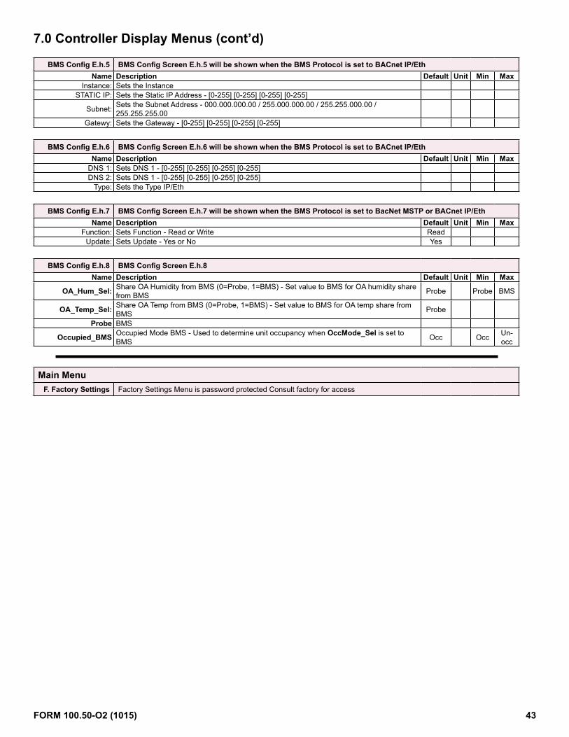
BMS Config E.h.5 BMS Config Screen E.h.5 will be shown when the BMS Protocol is set to BACnet IP/EthName Description Default Unit Min Max
Instance: Sets the InstanceSTATIC IP: Sets the Static IP Address - [0-255] [0-255] [0-255] [0-255]
Subnet: Sets the Subnet Address - 000.000.000.00 / 255.000.000.00 / 255.255.000.00 / 255.255.255.00
Gatewy: Sets the Gateway - [0-255] [0-255] [0-255] [0-255]
BMS Config E.h.6 BMS Config Screen E.h.6 will be shown when the BMS Protocol is set to BACnet IP/EthName Description Default Unit Min Max
DNS 1: Sets DNS 1 - [0-255] [0-255] [0-255] [0-255] DNS 2: Sets DNS 1 - [0-255] [0-255] [0-255] [0-255]
Type: Sets the Type IP/Eth
BMS Config E.h.7 BMS Config Screen E.h.7 will be shown when the BMS Protocol is set to BacNet MSTP or BACnet IP/EthName Description Default Unit Min Max
Function: Sets Function - Read or Write ReadUpdate: Sets Update - Yes or No Yes
BMS Config E.h.8 BMS Config Screen E.h.8Name Description Default Unit Min Max
OA_Hum_Sel: Share OA Humidity from BMS (0=Probe, 1=BMS) - Set value to BMS for OA humidity share from BMS Probe Probe BMS
OA_Temp_Sel: Share OA Temp from BMS (0=Probe, 1=BMS) - Set value to BMS for OA temp share from BMS Probe
Probe BMS
Occupied_BMS Occupied Mode BMS - Used to determine unit occupancy when OccMode_Sel is set to BMS Occ Occ Un-
occ
Main MenuF. Factory Settings Factory Settings Menu is password protected Consult factory for access
7.0 Controller Display Menus (cont’d)
FORM 100.50-O2 (1015) 43

The BACnet® MSTP (Option BHB8) communication allows access to selected unit function parameters. The standard communication protocol is identified as BACnet® over MS/TP (Master Satellite / Token Passing). This protocol is used for communicating BACnet® over a network of BACnet® only controllers. The network is considered open communication, whereas any device on the network has the capability to receive input from any other controller on the network. In all Y Series units included on a BACnet® network, there are certain configuration parameters that need to be met before com-munication can be established with other devices. These settings and configuration parameters must be set properly or the device will not respond when prompted by other devices in the network. Follow the procedure below to modify the Bacnet MSTP parameters required by the BMS network.
8.1 BACnet® MSTP (Option BHB8) Communication
1. From the main menu navigate to E. Service and press the enter key to access the service menu.
2. From the service menu navigate to the h. BMS Config
submenu and press the enter key to select.
3. From the BMS Config screen E.h.1 verify that the
Protocol: field is set to Bacnet MSTP. On a BAS card retrofit the Protocol: field may need to be set. To change the protocol press the enter key until the cursor is flashing on the Protocol: field and use the up or down key to scroll through the available choices and select Bacnet MSTP then press enter to confirm the protocol change.
8.0 Communication Cards
With the addition of an optional BMS Communication card, the building automation system can remotely adjust setpoints and view status points and alarms. The current supported building automation protocols are:
• BACnet® MSTP (Option BHB8)• LonWorks® (Option BHB7)
Contact factory if additional protocol support is needed.
Communication Card (Option BHB7 or BHB8)
Press the enter key in succession until the cursor
is flashing in the uppermost left hand corner of the screen and use the down arrow key to navigate to the next screen.
4. From the BMS Config screen E.h.2 Press the enter key to access the Termconf PlugIn? Field and set the value to yes.
Press the enter key in succession until the cursor
is flashing in the uppermost left hand corner of the screen and use the down arrow key to navigate to the next screen.
FORM 100.50-O2 (1015) 44

LED Lights (4 above) Description TroubleshootingQuick green-off-green Communication with controller is established and working. -Slow red-off-red Communication is not established and no data is passing to card. 1. Confirm card is firmly plugged in.
2. Confirm BMS Protocol is set to BACnet MSTP
8.1 BACnet® MSTP (cont’d)
1) Serial port connection2) Terminal block for BACnet® network
(GND, +, -)3) MSTP status LED4) Controller status LED5) Line resistance jumpers6) Factory configuration push button
BACnet® Communication Card Layout
5. From Screen E.h.4 Set the desired values for the Instance:,Baudrate:, and Mac Addr:. typcally the MaxMasters: and MaxInfoFrames: do not need to be modified.
Press the enter key in succession until the cursor
is flashing in the uppermost left hand corner of the screen and use the down arrow key to navigate to the next screen.
6. The modified values from the previous screen E.h.4 will need to be saved. From Screen E.h.7 press the enter key to access the Function: field and use the up
arrow key to set the value to Write and then press the enter key to access the update field and use the up arrow key to set the value to yes. After a two second pulse the update value will return to the value of NO. the modified bacnet values are now saved.
After saving the new setpoints, the controller must
be power cycled to complete the process. Once the power has been restored and the bacnet card has initialized, return to the MSTP Setup screen E.h.4 to confirm the changes were accepted.
The BACnet® communication card has two sets of LEDs (Controller Status and MSTP Status), a push button, and three jumpers. The controller status LED indicates the status of communication between the card and the controller. It is located above the push button.
The MSTP status LED lights are located on the bottom side of the communi-cation card below the controller status LED. The MSTP LED indicates the sta-tus of communication between the card and the network. Wait at least one minute after setting the communication parameters and plugging in the com-munication cable before determining the status of the network communication.
LED Lights (3 above) Description TroubleshootingGreen with occasional red
Communication with network is established and working.
-
Green and red both on
Communication is not established and no data is passing to the card.
1. Confirm system and card baudrate are the same.2. Confirm card Max Master is equal to or greater than the Station (MAC) Address of the Master with the highest address.
The push button on the communication card is used to return the card to factory configuration. Read and follow the procedure below to reset the card.1. With controller OFF, depress and hold the push button located on the
BACnet board while powering the controller back ON.Continue to hold the button, while watching the Status LEDs. Wait at least 20 seconds; the Status LED will flash SLOWLY 3 times, red-off.
8.0 Communication Cards (Cont’d)
FORM 100.50-O2 (1015) 45

Insert all three jumpers on the unit at the start of network and the unit at the end of the network. DO NOT insert the jumpers on the intermediate units.
2. Once the flashing begins, release the push button. After the 3 red flashes, the LED comes on green. The LED then confirms recognition of the button by flashing QUICKLY 3 times red-off, and then comes on green again.
3. Wait for about one minute for the factory parameters to be loaded.The jumpers are used to create built in end-of-line resistance for a BACnet® MSTP network.
BACnet® MSTP Points List
Option D21 BACnet® Point ListAnalog VariablesName Description R/W BMS
Address Unit Default Min Max
CC_Temp Cooling Coil Discharge Air Temp R AV1 Deg FComp_Mod_Out DX Modulation Output % R AV2 % 0 100DA_NAClg_SP Discharge Air Temp Neutral Cooling SP R/W AV3 Deg F 70 50 100DA_NAHtg_SP Discharge Air Temp Neutral Heating SP R/W AV4 Deg F 70 50 140DA_SP Discharge Air Temp Active SP R AV5 Deg FDA_SpcClg_SP Discharge Air Temp Space Cooling SP R/W AV6 Deg F 55 50 100DA_SpcHtCl_SP Discharge Air Temp Space Heat Mode Cooling SP R/W AV7 Deg F 55 50 100DA_SpcHtg_SP Discharge Air Temp Space Heating Sp R/W AV8 Deg F 90 50 140DA_Temp Discharge Air Temp R AV9 Deg FDamper_Cmd Damper Output Command R AV10 % 0 100DhOADP_SP Dehum OA Dew Point SP R/W AV11 Deg F 58 50 100EF_Spd_Cmd Exhaust Fan Speed Command R AV12 % 15 100ERV_DA_Temp Energy Recovery Wheel Discharge Air Temp R AV13 Deg FDamper_BMS Damper Output BMS Command R/W AV14 % 0 100HX_Mod_Cmd Heating Modulation Command R AV15 % 0 100MA_Temp Mixed Air Temp R AV16 Deg FOA_Dew_Point Outside Air Dew Point R AV17 Deg F
OA_Hum_BMS Outside Air Humidity BMS -Sets OA Humidity when OA_Hum_Sel is set to 1=BMS R/W AV18 %rH
OA_Hum_Raw Outside Air Humidity R AV19 %rH
OA_Temp_BMS Outside Air Temp BMS - Sets OA Temp when OA_Temp_Sel is set to 1=BMS R/W AV20 Deg F
OA_Temp_Raw Outside Air Temp R AV21 Deg FOAChgOv_SP OA Change Over SP R/W AV22 Deg F 65 45 80RH_Mod_Out Reheat Modulation Output % R AV23 % 0 100SF_VFD_Cmd Supply Fan VFD Command R AV24 % 0 100Spc_Temp Space Temp R AV25 Deg FSpcEffClgSP Space Effective Cooling SP R AV26 Deg FSpcEffHtgSP Space Effective Heating SP R AV27 Deg FSpcTempSP Space Temp SP R/W AV28 Deg F 72 65 85RA_Temp Return Air Temperature R AV29 Deg FRA_Humidity Return Air Humidity R AV30 % rHEA_Temp Exhaust Air Temperature R AV31 Deg FEA_Humidity Exhaust Air Humidity R AV32 % rHSF_BMS Supply Fan Output BMS Command R/W AV33 % 0 100
• Jumper P1 adds a 510 ohm polarization resistance between the negative data line (-) and GND;
• Jumper P2 adds a 120 ohm terminal resistance between the two data lines (+) and (-);
• Jumper P3 adds a 510 ohm polarization resistance between the positive data line (+) and the +5 Vdc internal voltage.
8.1 BACnet® MSTP (Cont’d)
R = ReadW = Write
AV = Analog VariableBV = Binary Variable
FORM 100.50-O2 (1015) 46

Integer VariablesName Description R/W BMS
Address Unit Default Min Max
Bldg_Pressure* Building Static Pressure R AV1001 iwcBldg_Press_SP* Building Static Pressure SP R/W AV1002 iwc 100 -500 500Duct_Press_SP* Duct Static Pressure SP R/W AV1003 iwc 500 0 2500Spc_Hum Space Humidity R AV1004 %rHSpcHumSP Space Humidity SP R/W AV1005 %rH 55 35 75State_Sel State Select 2=AUTO 3=COOL 4=HEAT 5=OFF R/W AV1006 5 2 5OccMode_Sel Occ Mode Select 0= Schedule 1= Digital Input 2= BMS R/W AV1007 1 0 2Spc_CO2 Space CO2 R AV1008 ppmSpcCO2SP Space CO2 SP R/W AV1009 ppm 1,000 0 2,000Duct_Pressure* Duct Static Pressure R AV1010 iwc*Note: Divide by 1000 with the supervisory system to reflect the appropriate decimal precision.Digital VariablesName Description R/W BMS
Address Unit Default Min Max
Alm_Rly_Cmd Unit General Alarm Relay Command R BV1 Off OnComp_Alarm Modulating Compressor General Alarm R BV2 Off OnComp_Stg2_Cmd Compressor Stage 2 Command R BV3 Off OnComp_Stg3_Cmd Compressor Stage 3 Command R BV4 Off OnComp_Stg4_Cmd Compressor Stage 4 Command R BV5 Off OnEF_Cmd Exhaust Fan Cmd R BV6 Off OnEF_Sts Exhaust Fan Status R BV7 Off OnERV_Cmd Energy Recovery Wheel Command R BV8 Off OnExt_OCC Occupied Mode Input R BV9 Off OnExt_Switch_1 External Damper Position Sw 1 R BV10 Off OnExt_Switch_2 External Damper Position Sw 2 R BV11 Off OnHtr_1_Sts Gas Heater 1 Status R BV12 Off OnHtr_2_Sts Gas Heater 2 Status R BV13 Off OnHX_Stg1_Cmd Heating Stage 1 Command R BV14 Off OnHX_Stg2_Cmd Heating Stage 2 Command R BV15 Off OnHX_Stg3_Cmd Heating Stage 3 Command R BV16 Off OnHX_Stg4_Cmd Heating Stage 4 Command R BV17 Off OnHX_Stg5_Cmd Heating Stage 5 Command R BV18 Off OnHX_Stg6_Cmd Heating Stage 6 Command R BV19 Off OnNA_Clg_Md Neutral Air Cooling Mode R BV20 Off OnNA_Dehum_Md Neutral Air Dehum Mode R BV21 Off OnNA_Htg_Md Neutral Air Heating Mode R BV22 Off OnOA_Hum_Sel Share OA Humidity from BMS (0=Probe 1=BMS) R/W BV23 Off Off OnOA_Temp_Sel Share OA Temp from BMS (0=Probe 1=BMS) R/W BV24 Off Off OnOccupied Occupied Mode Status R BV25 Off On
Occupied_BMS Occupied Mode BMS - Sets Unit Occupancy when OccMode_Sel is set to 2=BMS R/W BV26 Off Off On
Phase_Alarm Phase Protection Alarm R BV27 Off OnPreheat_Cmd Electric Preheat Command R BV28 Off OnReheat_Alarm Modulating Reheat Compressor General Alarm R BV29 Off OnSafety_Sts Safety Input Status R BV30 Normal AlarmSF_Cmd Supply Fan Command R BV31 Off OnSF_Sts Supply Fan Status R BV32 Off OnSpc_Clg_Md Space Cooling Mode R BV33 Off OnSpc_Dehum_Md Space Dehum Mode R BV34 Off OnSpc_Htg_Md Space Heating Mode R BV35 Off OnSpc_HtgClg_Md Space Heating Cooling Mode R BV36 Off OnFilter_Sts Main or ERV Dirty Filter Status R BV37 Off On
8.0 Communication Cards (Cont’d)BACnet® MSTP Points List (Cont’d)
FORM 100.50-O2 (1015) 47

1. From the main menu navigate to E. Service and press the enter key to access the service menu.
2. From the service menu navigate to the h. BMS Config
submenu and press the enter key to select.
3. From the BMS Config screen E.h.1 verify that the Protocol: field is set to Lon. On a BAS card retrofit the Protocol: field may need to be set. To change the protocol press the enter key until the cursor is flashing on the Protocol: field and use the up or down key to scroll through the available choices and select Lon then press enter to confirm the protocol change.
When complete press the escape key to return to the
main menu.
The Lonworks communication card has the following components.
1. Serial port connection2. Terminal block for LonWorks® network (GND, A, B)3. Service pin4. Service green LED5. Anomaly red LED
To activate the service pin, simply short-circuit the two pins for an instant using the tip of a screwdriver or similar tool. The activation is confirmed by the lighting of the service LED.The service LED has several function listed below. LED Light Description Troubleshooting
Green1. Signals the status of the mode, as per the LonWorks protocol;2. Remains ON during the activation of the service pin;3. Remains ON for a second when receiving a WINK command from the network
The anomaly LED indicates the status of communication between the card and the controller. LED Light Description Troubleshooting
Off Communication with controller is established and working.
Red Communication is not established and no data is passing to the card. 1. Confirm card is firmly plugged in.2. Confirm BMS Protocol is set to LON.
8.2 LonWorks® (Option BHB7) Communication
LonWorks® is an open protocol that was originally developed by Echelon Corpora-tion. It is now maintained by Echelon in collaboration with members of the LonMark®
Interoperability Association. It requires the use of Echelon’s Neuron microprocessor to encode and decode the LonWorks® packets.The LonWorks® protocol is based on the concept of using standardized functional pro-files to control similar pieces of equipment. The LonWorks® (Option BHB7) communi-cation allows access to selected unit function parameters. The network is considered open communication, whereas any device on the network has the capability to receive input from any other controller on the network. In all Y Series units included on a Lon-Works® network, the unit protocol configuration parameters must be set before com-munication can be established with other devices.
Follow the procedure below to set the BMS protocol to LonWorks®.
FORM 100.50-O2 (1015) 48

Option D21 Lon Point ListAnalog VariablesName Description R/W Index Name NV Bit# TypeNV Unit Default Min MaxCC_Temp Cooling Coil Discharge Air Temp R 1 nvoCC_Temp SNVT_temp_p Deg F/C
Comp_Mod_Out DX Modulation Output % R 2 nvoComp_Mod_Out SNVT_lev_percent % 0 100
DA_NAClg_SP Discharge Air Temp Neutral Cooling SP R/W 3 nviDA_NAClg_SP SNVT_temp_p Deg F/C 70/21.1 50/10 100/37.7
DA_NAHtg_SP Discharge Air Temp Neutral Heating SP R/W 4 nviDA_NAHtg_SP SNVT_temp_p Deg F/C 70/21.1 50/10 140/60
DA_SP Discharge Air Temp Active SP R 5 nvoDA_SP SNVT_temp_p Deg F/C
DA_SpcClg_SP Discharge Air Temp Space Cooling SP R/W 6 nviDA_SpcClg_SP SNVT_temp_p Deg F/C 55/12.7 50/10 100/37.7
DA_SpcHtCl_SP Discharge Air Temp Space Heat Mode Cooling SP R/W 7 nviDA_SpcHtCl_SP SNVT_temp_p Deg F/C 55/12.7 50/10 100/37.7
DA_SpcHtg_SP Discharge Air Temp Space Heating Sp R/W 8 nviDA_SpcHtg_SP SNVT_temp_p Deg F/C 90/32.2 50/10 140/60
DA_Temp Discharge Air Temp R 9 nvoDA_Temp SNVT_temp_p Deg F
Damper_Cmd Damper Output Command R 10 nvoDamper_Cmd SNVT_lev_percent % 0 100
DhOADP_SP Dehum OA Dew Point SP R/W 11 nviDhOADP_SP SNVT_temp_p Deg F/C 58/14.4 50/10 100/37.7
EF_Spd_Cmd Exhaust Fan Speed Command R 12 nvoEF_Spd_Cmd SNVT_lev_percent % 15 100
ERV_DA_Temp Energy Recovery Wheel Discharge Air Temp R 13 nvoERV_DA_Temp SNVT_temp_p Deg F/C
Damper_BMS Damper Output BMS Command R/W 14 nviDamper_BMS SNVT_lev_percent % 0 100
HX_Mod_Cmd Heating Modulation Command R 15 nvoHX_Mod_Cmd SNVT_lev_percent % 0 100
MA_Temp Mixed Air Temp R 16 nvoMA_Temp SNVT_temp_p Deg F/C
OA_Dew_Point Outside Air Dew Point R 17 nvoOA_Dew_Point SNVT_temp_p Deg F/C
OA_Hum_BMS1Outside Air Humidity BMS -Sets OA Humidity when OA_Hum_Sel is set to 1=BMS
R/W 18 nviOA_Hum_BMS SNVT_lev_percent %rH
OA_Hum_Raw Outside Air Humidity R 19 nvoOA_Hum_Raw SNVT_lev_percent %rH
OA_Temp_BMS Outside Air Temp BMS - Sets OA Temp when OA_Temp_Sel is set to 1=BMS R/W 20 nviOA_Temp_BMS SNVT_temp_p Deg F/C
OA_Temp_Raw Outside Air Temp R 21 nvoOA_Temp_Raw SNVT_temp_p Deg F/C
OAChgOv_SP OA Change Over SP R/W 22 nviOAChgOv_SP SNVT_temp_p Deg F/C 65/18.3 45/7.2 80/26.6
RH_Mod_Out Reheat Modulation Output % R 23 nvoRH_Mod_Out SNVT_lev_percent % 0 100
SF_VFD_Cmd Supply Fan VFD Command R 24 nvoSF_VFD_Cmd SNVT_lev_percent % 0 100
Spc_Temp Space Temp R 25 nvoSpc_Temp SNVT_temp_p Deg F/C
SpcEffClgSP Space Effective Cooling SP R 26 nvoSpcEffClgSP SNVT_temp_p Deg F/C
SpcEffHtgSP Space Effective Heating SP R 27 nvoSpcEffHtgSP SNVT_temp_p Deg F/C
SpcTempSP Space Temp SP R/W 28 nviSpcTempSP SNVT_temp_p Deg F/C 72/22.2 65/18.3 85/29.4
RA_Temp Return Air Temperature R 29 nvoRA_Temp SNVT_temp_p Deg F/C
RA_Humidity Return Air Humidity R 30 nvoRA_Humidity SNVT_lev_percent %rH
EA_Temp Exhaust Air Temperature R 31 nvoEA_Temp SNVT_temp_p Deg F/C
EA_Humidity Exhaust Air Humidity R 32 nvoEA_Humidity SNVT_lev_percent %rH
SF_BMS Supply Fan Output BMS Command R/W 33 nviSF_BMS SNVT_lev_percent % 0 100
LONworks® Point List
8.0 Communication Cards (Cont’d)8.2 LonWorks® (Option BHB7) Communication (Cont’d)
FORM 100.50-O2 (1015) 49

Integer VariablesName Description R/W Index Name NV Bit# TypeNV Unit Default Min Max
Bldg_Pressure Building Static Pressure R 1 nvoBldg_Pressure SNVT_press_p Pa
Bldg_Press_SP Building Static Pressure SP R/W 2 nviBldg_Press_SP SNVT_press_p Pa 24.9 -124 124
Duct_Press_SP Duct Static Pressure SP R/W 3 nviDuct_Press_SP SNVT_press_p Pa 124 0 622
Spc_Hum2 Space Humidity R 4 nvoSpc_Hum SNVT_lev_percent %rH
SpcHumSP3 Space Humidity SP R/W 5 nviSpcHumSP SNVT_lev_percent %rH 55 35 75
State_Sel State Select 2=AUTO 3=COOL 4=HEAT 5=OFF R/W 6 nviState_Sel SNVT_count 5 2 5
OccMode_Sel Occ Mode Select 0= Schedule 1= Digital Input 2= BMS R 7 nvoOccMode_Sel SNVT_count 1 0 2
Spc_CO2 Space CO2 R 8 nvoSpc_CO2 SNVT_ppm ppm
SpcCO2SP Space CO2 SP R/W 9 nviSpcCO2SP SNVT_ppm ppm 1,000
Duct_Pressure Duct Static Pressure R 10 nviDuct_Pressure SNVT_press_p Pa
Note 1: Divide the BMS humidity value by 20 before writing to the OA_Hum_BMS variable (scale 1=20%).Note 2: Multiply the Spc_Humidity value by 10 (scale 1=10%).Note 3: Divide the desired space humidity set point value by 10 before writing to the SpcHumSP variable (scale 1=10%).
Digital VariablesName Description R/W Index Name NV Bit# TypeNV Unit Default Min Max
OA_Hum_Sel Share OA Humidity from BMS (0=Probe 1=BMS) R/W 23 nviOA_Hum_Sel SNVT_switch Off Off On
OA_Temp_Sel Share OA Temp from BMS (0=Probe 1=BMS) R/W 24 nviOA_Temp_Sel SNVT_switch Off Off On
Occupied Occupied Mode Status R 25 nvoOccupied SNVT_switch Off On
Occupied_BMSOccupied Mode BMS - Sets Unit Occupancy when OccMode_Sel is set to 2=BMS
R/W 26 nviOccupied_BMS SNVT_switch Off Off On
Digital Variables Digital Outputs
Name Description R/W Index Name NV Bit# TypeNV Unit Default Min Max
Alm_Rly_Cmd Unit General Alarm Relay Command R nvoDoStat1 0 SNVT_state Off On
Comp_Stg2_Cmd Compressor Stage 2 Command R nvoDoStat1 1 SNVT_state Off On
Comp_Stg3_Cmd Compressor Stage 3 Command R nvoDoStat1 2 SNVT_state Off On
Comp_Stg4_Cmd Compressor Stage 4 Command R nvoDoStat1 3 SNVT_state Off On
EF_Cmd Exhaust Fan Cmd R nvoDoStat1 4 SNVT_state Off On
ERV_Cmd Energy Recovery Wheel Command R nvoDoStat1 5 SNVT_state Off On
HX_Stg1_Cmd Heating Stage 1 Command R nvoDoStat1 6 SNVT_state Off On
HX_Stg2_Cmd Heating Stage 2 Command R nvoDoStat1 7 SNVT_state Off On
HX_Stg3_Cmd Heating Stage 3 Command R nvoDoStat1 8 SNVT_state Off On
HX_Stg4_Cmd Heating Stage 4 Command R nvoDoStat1 9 SNVT_state Off On
HX_Stg5_Cmd Heating Stage 5 Command R nvoDoStat1 10 SNVT_state Off On
HX_Stg6_Cmd Heating Stage 6 Command R nvoDoStat1 11 SNVT_state Off On
Preheat_Cmd Electric Preheat Command R nvoDoStat1 12 SNVT_state Off On
SF_Cmd Supply Fan Command R nvoDoStat1 13 SNVT_state Off On
LONworks® Point List (Cont’d)
FORM 100.50-O2 (1015) 50

Digital Variables Digital Inputs
Name Description R/W Index Name NV Bit# TypeNV Unit Default Min Max
Comp_Alarm Modulating Compressor General Alarm R nvoDiStat1 0 SNVT_state Off On
EF_Sts Exhaust Fan Status R nvoDiStat1 1 SNVT_state Off On
Ext_OCC Occupied Mode Input R nvoDiStat1 2 SNVT_state Off On
Ext_Switch_1 External Damper Position Sw 1 R nvoDiStat1 3 SNVT_state Off On
Ext_Switch_2 External Damper Position Sw 2 R nvoDiStat1 4 SNVT_state Off On
Htr_1_Sts Gas Heater 1 Status R nvoDiStat1 5 SNVT_state Off On
Htr_2_Sts Gas Heater 2 Status R nvoDiStat1 6 SNVT_state Off On
Phase_Alarm Phase Protection Alarm R nvoDiStat1 7 SNVT_state Off On
Reheat_Alarm Modulating Reheat Compressor General Alarm R nvoDiStat1 8 SNVT_state Off On
Safety_Sts Safety Input Status R nvoDiStat1 9 SNVT_state Normal Alarm
SF_Sts Supply Fan Status R nvoDiStat1 10 SNVT_state Off On
Filter_Sts Main or ERV Dirty Filter Status R nvoDiStat1 11 SNVT_state Off On
Digital Variables Unit Modes
Name Description R/W Index Name NV Bit# TypeNV Unit Default Min Max
NA_Clg_Md Neutral Air Cooling Mode R nvoMdStat1 0 SNVT_state Off On
NA_Dehum_Md Neutral Air Dehum Mode R nvoMdStat1 1 SNVT_state Off On
NA_Htg_Md Neutral Air Heating Mode R nvoMdStat1 2 SNVT_state Off On
Spc_Clg_Md Space Cooling Mode R nvoMdStat1 3 SNVT_state Off On
Spc_Dehum_Md Space Dehum Mode R nvoMdStat1 4 SNVT_state Off On
Spc_Htg_Md Space Heating Mode R nvoMdStat1 5 SNVT_state Off On
Spc_HtgClg_Md Space Heating Cooling Mode R nvoMdStat1 6 SNVT_state Off On
8.0 Communication Cards (Cont’d)8.2 LonWorks® (Option BHB7) Communication (Cont’d)LONworks® Point List (Cont’d)
FORM 100.50-O2 (1015) 51

P.O. Box 1592, York, Pennsylvania USA 17405-1592 800-861-1001 Subject to change without notice. Printed in USACopyright © by Johnson Controls 2015 www.johnsoncontrols.com ALL RIGHTS RESERVEDForm 100.55-O2 (1015)Issue Date: October 2015 Supersedes: 100.55-O2 (1214)