Embed Size (px)
Citation preview
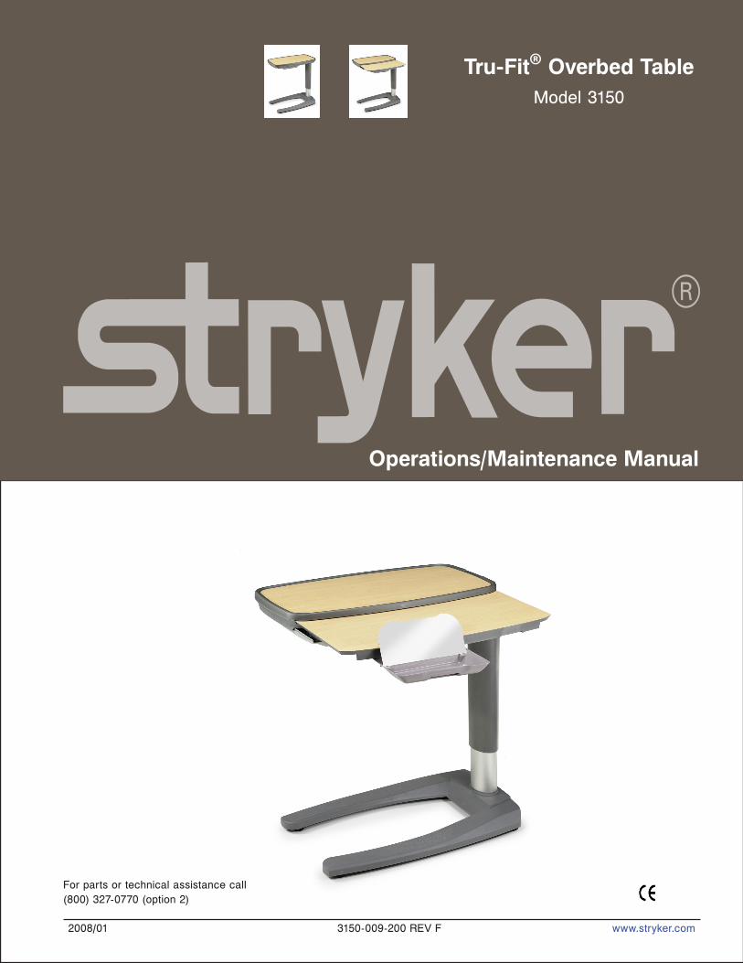
Tru-Fit® Overbed TableModel 3150
2008/01 3150-009-200 REV F www.stryker.com
Operations/Maintenance Manual
For parts or technical assistance call(800) 327-0770 (option 2)


www.stryker.com 3150-009-200 REV F 3
Table of Contents
Introduction . . . . . . . . . . . . . . . . . . . . . . . . . . . . . . . . . . . . . . . . . . . . . . . . . . . . . . . . . . . . . . . . . . . . . . . . . . . . . . 4
Intended Use . . . . . . . . . . . . . . . . . . . . . . . . . . . . . . . . . . . . . . . . . . . . . . . . . . . . . . . . . . . . . . . . . . . . . . . . . . 4
Specifications . . . . . . . . . . . . . . . . . . . . . . . . . . . . . . . . . . . . . . . . . . . . . . . . . . . . . . . . . . . . . . . . . . . . . . . . . 4
Warning / Caution / Note Definition. . . . . . . . . . . . . . . . . . . . . . . . . . . . . . . . . . . . . . . . . . . . . . . . . . . . . . . . . . 5
Symbols . . . . . . . . . . . . . . . . . . . . . . . . . . . . . . . . . . . . . . . . . . . . . . . . . . . . . . . . . . . . . . . . . . . . . . . . . . . . . . . . . 5
Summary of Safety Precautions . . . . . . . . . . . . . . . . . . . . . . . . . . . . . . . . . . . . . . . . . . . . . . . . . . . . . . . . . . . . . . . 6
Single Top With or Without Optional Vanity . . . . . . . . . . . . . . . . . . . . . . . . . . . . . . . . . . . . . . . . . . . . . . . . . . . . 7
Operations . . . . . . . . . . . . . . . . . . . . . . . . . . . . . . . . . . . . . . . . . . . . . . . . . . . . . . . . . . . . . . . . . . . . . . . . . . . . . . . 8
Split Top With Optional Vanity . . . . . . . . . . . . . . . . . . . . . . . . . . . . . . . . . . . . . . . . . . . . . . . . . . . . . . . . . . . . . 8
Clip Operation . . . . . . . . . . . . . . . . . . . . . . . . . . . . . . . . . . . . . . . . . . . . . . . . . . . . . . . . . . . . . . . . . . . . . . . . . 9
Bin Operation . . . . . . . . . . . . . . . . . . . . . . . . . . . . . . . . . . . . . . . . . . . . . . . . . . . . . . . . . . . . . . . . . . . . . . . . 10
Checklist . . . . . . . . . . . . . . . . . . . . . . . . . . . . . . . . . . . . . . . . . . . . . . . . . . . . . . . . . . . . . . . . . . . . . . . . . . . . 11
Cleaning. . . . . . . . . . . . . . . . . . . . . . . . . . . . . . . . . . . . . . . . . . . . . . . . . . . . . . . . . . . . . . . . . . . . . . . . . . . . . . . . 11
Service Information. . . . . . . . . . . . . . . . . . . . . . . . . . . . . . . . . . . . . . . . . . . . . . . . . . . . . . . . . . . . . . . . . . . . . . . . 13
Optional Storage Compartment Removal . . . . . . . . . . . . . . . . . . . . . . . . . . . . . . . . . . . . . . . . . . . . . . . . . . . . 13
Primary Top Replacement (Single Top and Single Top with Vanity Only) . . . . . . . . . . . . . . . . . . . . . . . . . . . . . 13
Primary Top Replacement (Split Top with Vanity Only). . . . . . . . . . . . . . . . . . . . . . . . . . . . . . . . . . . . . . . . . . . 14
Secondary Top Replacement (Split Top Only) . . . . . . . . . . . . . . . . . . . . . . . . . . . . . . . . . . . . . . . . . . . . . . . . . 14
Upper Column Replacement. . . . . . . . . . . . . . . . . . . . . . . . . . . . . . . . . . . . . . . . . . . . . . . . . . . . . . . . . . . . . . 15
Gas Spring Replacement . . . . . . . . . . . . . . . . . . . . . . . . . . . . . . . . . . . . . . . . . . . . . . . . . . . . . . . . . . . . . . . . 15
Caster Replacement . . . . . . . . . . . . . . . . . . . . . . . . . . . . . . . . . . . . . . . . . . . . . . . . . . . . . . . . . . . . . . . . . . . 15
Base Hood Replacement . . . . . . . . . . . . . . . . . . . . . . . . . . . . . . . . . . . . . . . . . . . . . . . . . . . . . . . . . . . . . . . . 16
Vanity Tray Replacement (Single Top Only). . . . . . . . . . . . . . . . . . . . . . . . . . . . . . . . . . . . . . . . . . . . . . . . . . . 17
Vanity Tray Replacement (Split Top Only) . . . . . . . . . . . . . . . . . . . . . . . . . . . . . . . . . . . . . . . . . . . . . . . . . . . . 17
Vanity Tray Mirror Replacement . . . . . . . . . . . . . . . . . . . . . . . . . . . . . . . . . . . . . . . . . . . . . . . . . . . . . . . . . . . 18
Optional Storage Compartment Installation Instructions . . . . . . . . . . . . . . . . . . . . . . . . . . . . . . . . . . . . . . . . . . 18
Single Top Overbed Table Assembly, Without Vanity . . . . . . . . . . . . . . . . . . . . . . . . . . . . . . . . . . . . . . . . . . . . . . . 19
Single Top Assembly, Without Vanity . . . . . . . . . . . . . . . . . . . . . . . . . . . . . . . . . . . . . . . . . . . . . . . . . . . . . . . . . . . 20
Single Top Overbed Table Assembly, With Vanity. . . . . . . . . . . . . . . . . . . . . . . . . . . . . . . . . . . . . . . . . . . . . . . . . . 22
Single Top Assembly, With Vanity . . . . . . . . . . . . . . . . . . . . . . . . . . . . . . . . . . . . . . . . . . . . . . . . . . . . . . . . . . . . . 23
Split Top Overbed Table Assembly . . . . . . . . . . . . . . . . . . . . . . . . . . . . . . . . . . . . . . . . . . . . . . . . . . . . . . . . . . . . 25
Split Top Assembly . . . . . . . . . . . . . . . . . . . . . . . . . . . . . . . . . . . . . . . . . . . . . . . . . . . . . . . . . . . . . . . . . . . . . . . . 26
Gas Spring. . . . . . . . . . . . . . . . . . . . . . . . . . . . . . . . . . . . . . . . . . . . . . . . . . . . . . . . . . . . . . . . . . . . . . . . . . . . . . 28
Base Assembly. . . . . . . . . . . . . . . . . . . . . . . . . . . . . . . . . . . . . . . . . . . . . . . . . . . . . . . . . . . . . . . . . . . . . . . . . . . 29
Optional Storage Compartment . . . . . . . . . . . . . . . . . . . . . . . . . . . . . . . . . . . . . . . . . . . . . . . . . . . . . . . . . . . . . . . 31
Warranty . . . . . . . . . . . . . . . . . . . . . . . . . . . . . . . . . . . . . . . . . . . . . . . . . . . . . . . . . . . . . . . . . . . . . . . . . . . . . . . 34
One Year Warranty . . . . . . . . . . . . . . . . . . . . . . . . . . . . . . . . . . . . . . . . . . . . . . . . . . . . . . . . . . . . . . . . . . . . 34
To Obtain Parts and Service . . . . . . . . . . . . . . . . . . . . . . . . . . . . . . . . . . . . . . . . . . . . . . . . . . . . . . . . . . . . . 34
Return Authorization. . . . . . . . . . . . . . . . . . . . . . . . . . . . . . . . . . . . . . . . . . . . . . . . . . . . . . . . . . . . . . . . . . . . 34
Damaged Merchandise . . . . . . . . . . . . . . . . . . . . . . . . . . . . . . . . . . . . . . . . . . . . . . . . . . . . . . . . . . . . . . . . . 34
International Warranty Clause. . . . . . . . . . . . . . . . . . . . . . . . . . . . . . . . . . . . . . . . . . . . . . . . . . . . . . . . . . . . . 34
Service Contract Coverage . . . . . . . . . . . . . . . . . . . . . . . . . . . . . . . . . . . . . . . . . . . . . . . . . . . . . . . . . . . . . . 35
Service Contract Programs . . . . . . . . . . . . . . . . . . . . . . . . . . . . . . . . . . . . . . . . . . . . . . . . . . . . . . . . . . . . . . 35

4 3150-009-200 REV F www.stryker.com
Introduction
InTended Use
This manual is designed to assist you with the maintenance of Stryker Overbed Table, Model 3150. Carefully read this manual thoroughly before using the equipment or beginning maintenance on it. To ensure safe operation of this equipment, it is recommended that methods and procedures be established for educating and training staff on the safe operation of this product.
speCIFICaTIOns
Overbed Table wIThOUT OpTIOnal sTOrage COMparTMenT
single Top without vanity single Top with vanity split Top with vanity
Base Length 32” 32” 32”
Overall Table Top Length/Width 31” / 17.5” 31” / 17.5” 31” / 17.5”
Minimum/Maximum Table Top Height 27” / 43.75” 27” / 43.75” 29” / 45.5”
Weight of Table 43 pounds 50 pounds 61 pounds
Weight Capacity of Table * 75 pounds 75 pounds 75 pounds
* Safe Working Load 25 lbs
Stryker reserves the right to change specifications without notice.
Overbed Table wITh OpTIOnal sTOrage COMparTMenT
single Top without vanity single Top with vanity split Top with vanity
Base Length 32” 32” 32”
Overall Table Top Length/Width 42.75” / 17.5” 42.75” / 17.5” 42.75” / 17.5”
Minimum/Maximum Table Top Height 27” / 43.75” 27” / 43.75” 29” / 45.5”
Weight of Table 68 pounds 75 pounds 86 pounds
Weight Capacity of Table * 75 pounds 75 pounds 75 pounds
saFe OperaTIng lOads OF OpTIOnal sTOrage COMparTMenT
Top Shelf 20 pounds
Bottom Shelf 20 pounds
Return To Table of Contents

www.stryker.com 3150-009-200 REV F 5
Introduction
warnIng / CaUTIOn / nOTe deFInITIOnThe words WARNING, CAUTION, and NOTE carry special meanings and should be carefully reviewed.
warnIng
Alerts the reader about a situation, which if not avoided, could result in death or serious injury. It may also describe potential serous adverse reactions and safety hazards.
CaUTIOn
Alerts the reader of a potentially hazardous situation, which if not avoided, may result in minor or moderate injury to the user or patient or damage to the equipment or other property. This includes special care necessary for the safe and effective use of the device and the care necessary to avoid damage to a device that may occur as a result of use or misuse.
noteThis provides special information to make maintenance easier or important instructions clearer.
Safe Working Load Symbol
Warning, consult accompanying documentation
symbols
Return To Table of Contents
6 3150-009-200 REV F www.stryker.com
warnIngs
Do not lean on table. Leaning on table may cause the table to tip which may result in injury to the individual or •damage to the unit.
CaUTIOns
Use discretion in the placement of personal items located near or by biohazardous/unsanitary materials.•Do not apply lubricant of any kind to the gas spring. Lubricant will damage the gas spring. •
summary of safety precautions
Return To Table of Contents

www.stryker.com 3150-009-200 REV F 7
Pull up on the table top to raise it. 1. To unlock and lower the table top, squeeze handle (A) while guiding the table top down. 2. Pull out the optional vanity (B) with the flip up mirror in either direction (if equipped). 3.
warnIng
do not lean on table. Leaning on table may cause the table to tip which may result in injury to the individual or damage to the unit.
A
B
sIngle TOp wITh Or wIThOUT OpTIOnal vanITy
Operations
Return To Table of Contents

Return To Table of Contents
Pull up on the table top to raise it. 1. To unlock and lower the table top, squeeze handle (A) while guiding the table top down. 2. Grasp and pull any of the four handles (B) to slide out the secondary top in either direction. 3. Pull out the vanity (C) with the flip up mirror in either direction. 4.
warnIng
do not lean on table. Leaning on table may cause the table to tip which may result in injury to the individual or damage to the unit.
A
C
B
B
B
B
(behind mirror)
splIT TOp wITh OpTIOnal vanITy
8 3150-009-200 REV F www.stryker.com
Operations
Return To Table of Contents
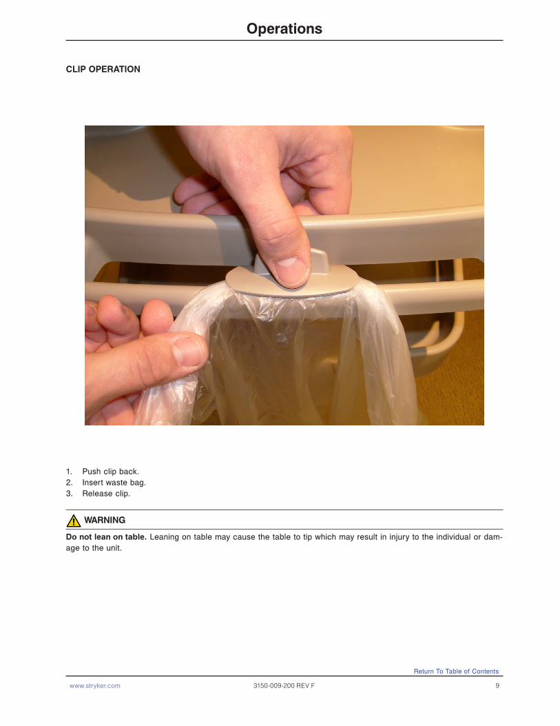
Push clip back.1. Insert waste bag.2. Release clip. 3.
warnIng
do not lean on table. Leaning on table may cause the table to tip which may result in injury to the individual or dam-age to the unit.
ClIp OperaTIOn
www.stryker.com 3150-009-200 REV F 9
Operations

10 3150-009-200 REV F www.stryker.com
Pull bin out to access storage. 1. Push bin in to close.2.
warnIng
do not lean on table. Leaning on table may cause the table to tip which may result in injury to the individual or damage to the unit.
bIn OperaTIOn
Operations
Return To Table of Contents

www.stryker.com 3150-009-200 REV F 11
CheCklIsT
_____ All fasteners secure.
_____ Top and laminate intact - not damaged.
_____ Top edge mold intact - not damaged.
_____ Release handle locking and releasing properly.
_____ All casters secure and swiveling properly.
_____ No debris in casters.
_____ Base hood intact - not damaged.
_____ Optional pull-out vanity and mirror intact and secure.
_____ Optional Storage Compartment intact - not damaged.
CaUTIOn
Do not apply lubricant of any kind to the gas spring. Lubricant will damage the gas spring.
Overbed Table Serial Number:
Completed by: _______________________________________ Date: ___________________
Cleaning
The Center for Disease Control recommends a 1:4 mixture of bleach and water for disinfection. Thoroughly rinse the solution from the product surface. If other hospital-grade cleaning agents are used, follow the instructions provided by the cleaning solution’s manufacturer. Wipe the surface with a soft, dry cloth to remove any moisture. As part of routine maintenance, follow steps 1-5 of the upper column replacement procedure on page 15 to remove the top assembly from the base assembly. Use a soft cloth to remove dust and debris from the top weldment tube and the inside of the base column. Spray the top weldment tube with pure silicone spray before reassembly. dO nOT use WD-40 or any other lubricant or damage to the table could occur.
preventative Maintenance
Return To Table of Contents

12 3150-009-200 REV F www.stryker.com
problem / Failure recommended action
Table drifts up.Make sure original table top and storage compartment (if applicable) remain attached to the base. If so, then replace the gas spring (see page 15).
Table drifts down without weight on table top.If the table is difficult to raise and drops back down when released, replace the gas spring (see page 15).
Table has a spongy feeling.This is normal as long as long as it does not drift down.
Table drifts down with weight on table top.Adjust the gas spring lock pin for more clearance so there is a little play in the handle.
Table randomly drifts down with light weight load applied.
Replace gas spring (see page 15).
Squeaky noise in between base and column.Add 1/4” washers under the four main base bolts. note: remove and reinstall bolts one at a time.
Identify the problem from the table below and follow the instructions for resolution. If assistance is needed at any time during troubleshooting, please contact a service technician at 1-800-327-0770 option 2.
Troubleshooting guide
Return To Table of Contents

www.stryker.com 3150-009-200 REV F 13
OpTIOnal sTOrage COMparTMenT reMOval
Tools required:
T25 Torx Driver•T27 Torx Driver•Regular Screwdriver •
procedure:
Raise the table to its full height. 1.
Remove the upper column cover by pulling 2.
outward slightly on both sides and pulling out
and down.
Using a regular screwdriver, unlock the lock tabs 3.
and remove the upper column clamp.
Using a T25 Torx driver, remove the T25 Torx 4.
screw from the top front of the upper column.
Remove the storage compartment. 5.
prIMary TOp replaCeMenT (sIngle TOp and sIngle TOp wITh vanITy Only)
Tools required:
#2 Phillips Screwdriver•
warnIng
To avoid personal injury or damage to the table, support the table top before removing the screws securing it to the top support.
procedure:
If your unit has a storage compartment, follow the procedures above for Storage Compartment Removal, then 1.
proceed to step 2.
Lift the table to its highest height.2.
Using a Phillips screwdriver, remove the four #2 Phillips screws under the table top holding the top to the support 3.
weldment.
Lift off the table top. 4.
If your unit has a vanity tray installed, follow steps 5a through 5c. If not, proceed to step 6. 5.
a. Turn the table top over.
b. Using a Phillips screwdriver, remove the ten #10 Phillips screws holding the vanity tracks to the bottom
of the table top.
c. Remove the vanity tray from the table top.
Reverse procedures to install the new top. 6.
service Information
Upper Column Cover
Upper Column Clamp
Return To Table of Contents

14 3150-009-200 REV F www.stryker.com
service Information
prIMary TOp replaCeMenT (splIT TOp wITh vanITy Only)
Tools required: #2 Phillips Screwdriver•3/8” Nut Driver•
warnIng
To avoid personal injury or damage to the table, support the table top before removing the screws securing it to the top support.
procedure:
If your unit has a storage compartment, follow the procedures above for Storage Compartment Removal, then 1.
proceed to step 2.
Lift the table to its highest height.2.
Using a 3/8” nut driver, remove the 3/8” acorn nuts from the bottom of the table at each of the four corners.3.
Lift off the table top. 4.
Turn the table top upside down and separate the primary and secondary tops.5.
Using a Phillips screwdriver, remove the six #10 Phillips screws holding the two slides on the primary table top and 6.
set them aside.
Reverse procedures to install the new top. 7.
seCOndary TOp replaCeMenT (splIT TOp Only)
Tools required: 3/8” Nut Driver •
warnIng
To avoid personal injury or damage to the table:Support the table top before removing the screws securing it to the top support.•
While turning the table top over, securely hold the top on the sides to prevent the primary and secondary tops •
from separating.
procedure:
If your unit has a storage compartment, follow the procedures on 1. page 13 for Storage Compartment Removal then
proceed to step 2.
Using a 3/8” nut driver, remove the 3/8” acorn nuts from the bottom of the table at each of the four corners. 2.
Lift off the table top. 3.
Turn the table top upside down and separate the primary and secondary tops. 4.
Turn over the secondary top, turn the vanity tray approximately 45 and remove it from the table top. 5.
Reverse procedures to install the new top.6.
Return To Table of Contents
warnIng
To avoid personal injury or damage to the table, while turning the table top over, securely hold the top on the sides to prevent the primary and secondary tops from separating.

www.stryker.com 3150-009-200 REV F 15
service Information
Upper COlUMn replaCeMenT
Tools required: #2 Phillips Screwdriver•T25 Torx Driver•T27 Torx Driver•
procedure:
If your unit has a storage compartment, follow the procedures on 1. page 13 for Storage Compartment Removal then
proceed to step 2.
Using a T25 Torx driver, remove the three T25 Torx screws from the top of the upper column and lower the column 2.
down to the base.
Using a T27 Torx driver, remove the two T27 Torx screws holding the upper bushing to the lower column. 3.
Lift the top assembly straight up and out of the lower column and set it aside. 4.
Reverse procedures to reassemble.5.
gas sprIng replaCeMenT
Tools required: T25 Torx Driver •T27 Torx Driver •
procedure:
If your unit has a storage compartment, follow the procedures on 1. page 13 for Storage Compartment Removal then
proceed to step 2.
Using a T25 Torx driver, remove the three T25 Torx screws from the top of the upper column and lower the column 2.
down to the base.
Using a T27 Torx driver, remove the two T27 Torx screws holding the upper bushing to the lower column. 3.
Lift the top assembly out of the lower column and set it aside. 4.
Remove the gas spring release lever from the gas cylinder, push down on the lever and pull it out while moving it 5.
slightly from side to side.
Remove the rue clip from the clevis pin holding the gas spring assembly to the top weldment and remove the 6.
clevis pin.
Reverse t7. o install the new gas spring. nOTe: When reinstalling the upper bushing, compress the gas spring slightly before tightening the two T27 Torx screws holding the bushing to the lower column.
CasTer replaCeMenT
Tools required: Cordless Drill, 3/16” Drill Bit•Pop Rivet Gun with 3/16” Tip •
procedure:
Fully raise the table top. 1.
While maintaining a secure grip on the table, carefully flip it forward or turn it on its side to allow access to the 2.
damaged caster.
Using a cordless drill and 3/16” drill bit, drill out the two rivets and remove the damaged caster. 3.
Using a pop rivet gun with a 3/16” tip, install the new caster using two new pop rivets. 4.
Return To Table of Contents
16 3150-009-200 REV F www.stryker.com
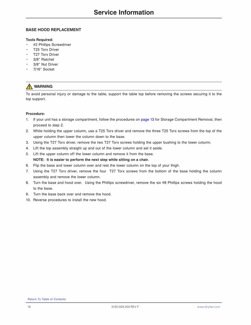
base hOOd replaCeMenT
Tools required: #2 Phillips Screwdriver•T25 Torx Driver•T27 Torx Driver•3/8” Ratchet•3/8” Nut Driver •7/16” Socket •
warnIng
To avoid personal injury or damage to the table, support the table top before removing the screws securing it to the top support.
procedure:
If your unit has a storage compartment, follow the procedures on 1. page 13 for Storage Compartment Removal, then
proceed to step 2.
While holding the upper column, use a T25 Torx driver and remove the three T25 Torx screws from the top of the 2.
upper column then lower the column down to the base.
Using the T27 Torx driver, remove the two T27 Torx screws holding the upper bushing to the lower column. 3.
Lift the top assembly straight up and out of the lower column and set it aside. 4.
Lift the upper column off the lower column and remove it from the base. 5.
nOTe: It is easier to perform the next step while sitting on a chair.
Flip the base and lower column over and rest the lower column on the top of your thigh. 6.
Using the T27 Torx driver, remove the four T27 Torx screws from the bottom of the base holding the column 7.
assembly and remove the lower column.
Turn the base and hood over. Using the Phillips screwdriver, remove the six #8 Phillips screws holding the hood 8.
to the base.
Turn the base back over and remove the hood. 9.
Reverse procedures to install the new hood. 10.
service Information
Return To Table of Contents

www.stryker.com 3150-009-200 REV F 17
service Information
vanITy Tray replaCeMenT (sIngle TOp Only)
Tools required: #2 Phillips Screwdriver•
warnIng
To avoid personal injury or damage to the table, support the table top before removing the screws securing it to the top support.
procedure:
Raise the table top to its highest height. 1.
Using a Phillips screwdriver, remove the four #10 Phillips screws under the table top holding the top to the support 2.
weldment.
Lift off the table top. 3.
Turn over the table top. 4.
Using a Phillips screwdriver, remove the five #10 Phillips screws holding one of the vanity tracks to the bottom of 5.
the table top.
Remove the vanity from the table top. 6.
Reverse procedures to install the new vanity tray. 7.
vanITy Tray replaCeMenT (splIT TOp Only)
Tools required: 3/8” Nut Driver•
warnIng
To avoid personal injury or damage to the table, support the table top before removing the nuts securing it to the top support.
procedure:
Raise the table top to its highest height. 1.
Using a 3/8” nut driver, remove the 3/8” acorn nuts from the bottom of the table at each of the four corners. 2.
Lift off the table top. 3.
warnIng
To avoid personal injury or damage to the table, while turning the table top over, securely hold the top on the sides to prevent the primary and secondary tops from separating.
Turn over the table top, turn the vanity tray approximately 454. 0 and remove it from the table top.
Reverse procedures to install the new vanity tray.5.
Return To Table of Contents

18 3150-009-200 REV F www.stryker.com
service Information
vanITy Tray MIrrOr replaCeMenT
Tools required: None•
procedure:
Open the side of the vanity tray with the broken mirror and flip up the mirror. 1.
While holding the top of the broken mirror with one hand, use your other hand to flex the bottom of the mirror in 2.
the middle and remove it from the vanity.
Reverse procedures to install the new mirror. 3.
OpTIOnal sTOrage COMparTMenT InsTallaTIOn InsTrUCTIOns
Tools required: T25 Torx Driver•T27 Torx Driver•
CaUTIOn
Make sure that nothing is on top of the unit and that you have the unit fully supported so not to cause damage to the OBT nor to cause injury to yourself.
procedure:
Install the increased pressure gas spring by following the gas spring replacement instructions located in this 1.
Operations/Maintenance manual for the model of the Overbed Table (OBT) that the option is being added to.
nOTe: leave the two T25 screws removed from the handle side of the outer column out and discard.
Raise the OBT to the full upright position and then flip the unit on end so that the column is nearest the ceiling. 2.
Set the Storage Compartment unit on top of the outer column just under the release handle. Using the 2 Torx 3.
screws supplied with the kit, secure the unit to the top weldment where the two T25 Torx screws were removed.
Tighten securely.
Slide the upper column clamp into the bottom shelf which will lock when fully seated. The clamp slides downward 4.
with the curved section next to the table column.
Install the upper column cover by angling it towards the top tray and gently stretching it at the bottom, lock it over 5.
the frame assembly.
Install the two leg ballasts located under the base, adjacent to the casters by threading the self tapping T27 6.
screw supplied into the base weldment. A hole in the weldment exists for the screw.
nOTe: There is a left and right ballast and the ballasts are also keyed to the base cover.
Stand the OBT back upright and insert the storage bin. 7.
Test functionality of the OBT and storage bin and then return to service.8.
Return To Table of Contents

www.stryker.com 3150-009-200 REV F 19
single Top Overbed Table assembly, without vanity
For Reference Only: Part Number 3150-000-001
Item part no. part name Qty.
A 3150-010-001 Single Top, without Vanity (see page 20) 1B (see page 28) Gas Spring (Low Pressure) 1C 3150-001-000 Base Assembly (see page 29) 1D 0004-136-000 Pan Head Machine Screw 3E 0026-296-000 Gas Spring Clevis 1F 0027-019-000 Rue Clip 1G 0001-163-000 Flat Countersunk Head Screw 2
A
F
E
B
C
G
D
Return To Table of Contents
20 3150-009-200 REV F www.stryker.com
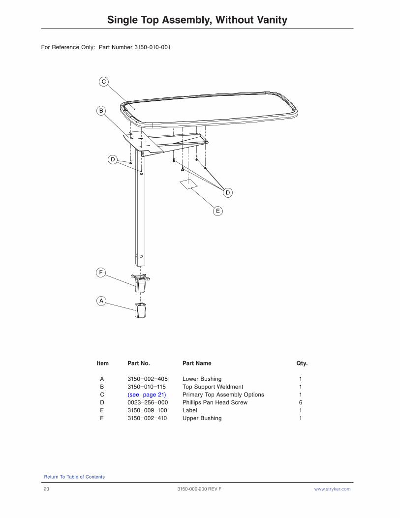
single Top assembly, without vanity
For Reference Only: Part Number 3150-010-001
Item part no. part name Qty.
A 3150−002−405 Lower Bushing 1 B 3150−010−115 Top Support Weldment 1 C (see page 21) Primary Top Assembly Options 1 D 0023−256−000 Phillips Pan Head Screw 6 E 3150−009−100 Label 1 F 3150−002−410 Upper Bushing 1
A
B
F
D
C
D
E
Return To Table of Contents

www.stryker.com 3150-009-200 REV F 21
single Top assembly, without vanity
Single Top Laminate / Edge Mold Options
laminate Color edge Mold Color Top part number
Hard Rock Maple Pewter 3150-092-441
Fine Oak Pewter 3150-092-442
Port Maple Pewter 3150-092-443
Wild Cherry Pewter 3150-092-446
Cayenne Maple Pewter 3150-092-447
Honey Maple Pewter 3150-092-448
Select Cherry Pewter 3150-092-449
Hard Rock Maple Coffee 3150-090-441
Fine Oak Coffee 3150-090-442
Port Maple Coffee 3150-090-443
Wild Cherry Coffee 3150-090-446
Cayenne Maple Coffee 3150-090-447
Honey Maple Coffee 3150-090-448
Select Cherry Coffee 3150-090-449
Hard Rock Maple Graphite 3150-091-441
Fine Oak Graphite 3150-091-442
Port Maple Graphite 3150-091-443
Wild Cherry Graphite 3150-091-446
Cayenne Maple Graphite 3150-091-447
Honey Maple Graphite 3150-091-448
Select Cherry Graphite 3150-091-449
Hard Rock Maple Light Chocolate 3150-089-441
Fine Oak Light Chocolate 3150-089-442
Port Maple Light Chocolate 3150-089-443
Wild Cherry Light Chocolate 3150-089-446
Cayenne Maple Light Chocolate 3150-089-447
Honey Maple Light Chocolate 3150-089-448
Select Cherry Light Chocolate 3150-089-449
Tops prior to 2/1/2005 (available as service parts Only)
Hearth Oak Pewter 3150-092-444
Royal Maple Pewter 3150-092-445
Hearth Oak Coffee 3150-090-444
Royal Maple Coffee 3150-090-445
Hearth Oak Graphite 3150-091-444
Royal Maple Graphite 3150-091-445
C
Return To Table of Contents
22 3150-009-200 REV F www.stryker.com
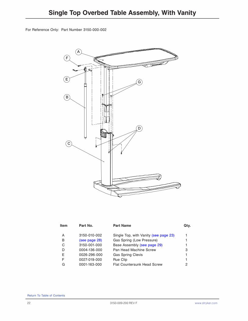
single Top Overbed Table assembly, with vanity
For Reference Only: Part Number 3150-000-002
Item part no. part name Qty.
A 3150-010-002 Single Top, with Vanity (see page 23) 1B (see page 28) Gas Spring (Low Pressure) 1C 3150-001-000 Base Assembly (see page 29) 1D 0004-136-000 Pan Head Machine Screw 3E 0026-296-000 Gas Spring Clevis 1F 0027-019-000 Rue Clip 1G 0001-163-000 Flat Countersunk Head Screw 2
A
F
E
B
C
G
D
Return To Table of Contents
www.stryker.com 3150-009-200 REV F 23
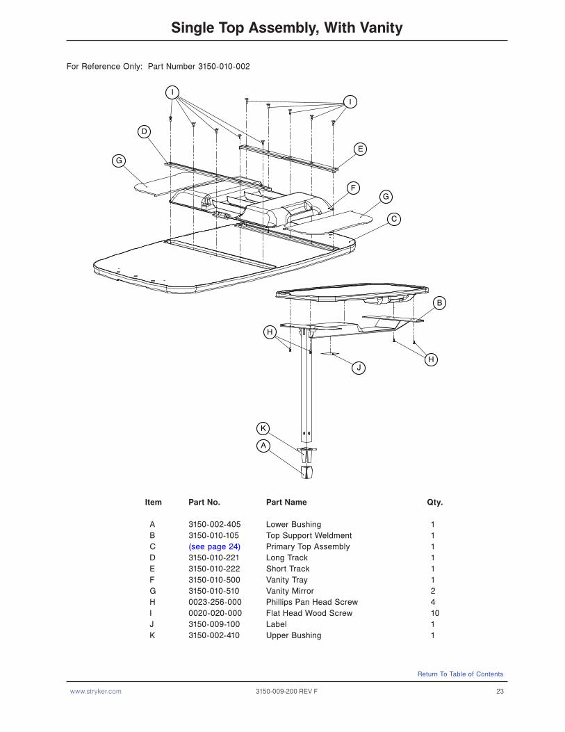
single Top assembly, with vanity
For Reference Only: Part Number 3150-010-002
Item part no. part name Qty.
A 3150-002-405 Lower Bushing 1B 3150-010-105 Top Support Weldment 1C (see page 24) Primary Top Assembly 1D 3150-010-221 Long Track 1E 3150-010-222 Short Track 1F 3150-010-500 Vanity Tray 1G 3150-010-510 Vanity Mirror 2H 0023-256-000 Phillips Pan Head Screw 4I 0020-020-000 Flat Head Wood Screw 10J 3150-009-100 Label 1K 3150-002-410 Upper Bushing 1
G
FG
D
II
E
C
H
J
K
A
B
H
Return To Table of Contents

24 3150-009-200 REV F www.stryker.com
single Top assembly, with vanity
Single Top Lmainate / Edge Mold Options
laminate Color efge Mold Color primary Top part number
Hard Rock Maple Pewter 3150-096-441
Fine Oak Pewter 3150-096-442
Port Maple Pewter 3150-096-443
Wild Cherry Pewter 3150-096-446
Cayenne Maple Pewter 3150-096-447
Honey Maple Pewter 3150-096-448
Select Cherry Pewter 3150-096-449
Hard Rock Maple Coffee 3150-097-441
Fine Oak Coffee 3150-097-442
Port Maple Coffee 3150-097-443
Wild Cherry Coffee 3150-097-446
Cayenne Maple Coffee 3150-097-447
Honey Maple Coffee 3150-097-448
Select Cherry Coffee 3150-097-449
Hard Rock Maple Graphite 3150-098-441
Fine Oak Graphite 3150-098-442
Port Maple Graphite 3150-098-443
Wild Cherry Graphite 3150-098-446
Cayenne Maple Graphite 3150-098-447
Honey Maple Graphite 3150-098-448
Select Cherry Graphite 3150-098-449
Hard Rock Maple Light Chocolate 3150-089-441
Fine Oak Light Chocolate 3150-089-442
Port Maple Light Chocolate 3150-089-443
Wild Cherry Light Chocolate 3150-089-446
Cayenne Maple Light Chocolate 3150-089-447
Honey Maple Light Chocolate 3150-089-448
Select Cherry Light Chocolate 3150-089-449
Tops prior to 2/1/2005 (available as service parts Only)
Hearth Oak Pewter 3150-096-444
Royal Maple Pewter 3150-096-445
Hearth Oak Coffee 3150-097-444
Royal Maple Coffee 3150-097-445
Hearth Oak Graphite 3150-098-444
Royal Maple Graphite 3150-098-445
C
Return To Table of Contents

www.stryker.com 3150-009-200 REV F 25
split Top Overbed Table assembly
For Reference Only: Part Number 3150-000-003
Item part no. part name Qty.
A 3150-010-003 Split Top Assembly (see page 26) 1B (see page 28) Gas Spring (Low Pressure) 1C 3150-001-000 Base Assembly (see page 29) 1D 0004-136-000 Pan Head Machine Screw 3E 0026-296-000 Gas Spring Clevis 1F 0027-019-000 Rue Clip 1G 0001-163-000 Flat Countersunk Head Screw 2
B
E
F
A
G
D
C
Return To Table of Contents
26 3150-009-200 REV F www.stryker.com
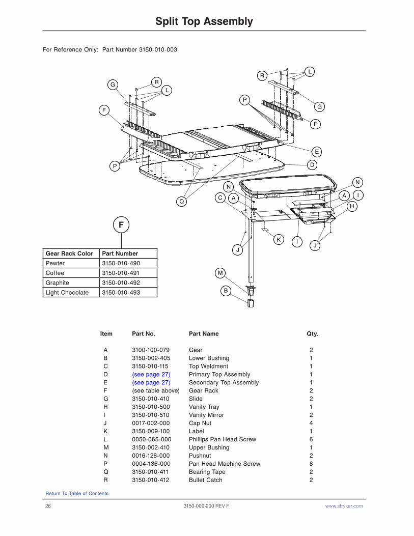
split Top assembly
For Reference Only: Part Number 3150-010-003
B
A A
L
G
GF
F
E
D
M
J
C
KJ
H
L
P
P
N
I
I
N
RR
Q
Item part no. part name Qty.
A 3100-100-079 Gear 2B 3150-002-405 Lower Bushing 1C 3150-010-115 Top Weldment 1D (see page 27) Primary Top Assembly 1E (see page 27) Secondary Top Assembly 1F (see table above) Gear Rack 2G 3150-010-410 Slide 2H 3150-010-500 Vanity Tray 1I 3150-010-510 Vanity Mirror 2J 0017-002-000 Cap Nut 4K 3150-009-100 Label 1L 0050-065-000 Phillips Pan Head Screw 6M 3150-002-410 Upper Bushing 1N 0016-128-000 Pushnut 2P 0004-136-000 Pan Head Machine Screw 8Q 3150-010-411 Bearing Tape 2R 3150-010-412 Bullet Catch 2
gear rack Color part number
Pewter 3150-010-490
Coffee 3150-010-491
Graphite 3150-010-492
Light Chocolate 3150-010-493
F
Return To Table of Contents

www.stryker.com 3150-009-200 REV F 27
split Top assembly
Split Top Laminate / Edge Mold Color Options d
laminate Color efge Mold Color primary Top part number secondary Top part number
Hard Rock Maple Pewter 3150-092-441 3150-094-441
Fine Oak Pewter 3150-092-442 3150-094-442
Port Maple Pewter 3150-092-443 3150-094-443
Wild Cherry Pewter 3150-092-446 3150-094-446
Cayenne Maple Pewter 3150-092-447 3150-094-447
Honey Maple Pewter 3150-092-448 3150-094-448
Select Cherry Pewter 3150-092-449 3150-094-449
Hard Rock Maple Coffee 3150-090-441 3150-093-441
Fine Oak Coffee 3150-090-442 3150-093-442
Port Maple Coffee 3150-090-443 3150-093-443
Wild Cherry Coffee 3150-090-446 3150-093-446
Cayenne Maple Coffee 3150-090-447 3150-093-447
Honey Maple Coffee 3150-090-448 3150-093-448
Select Cherry Coffee 3150-090-449 3150-093-449
Hard Rock Maple Graphite 3150-091-441 3150-095-441
Fine Oak Graphite 3150-091-442 3150-095-442
Port Maple Graphite 3150-091-443 3150-095-443
Wild Cherry Graphite 3150-091-446 3150-095-446
Cayenne Maple Graphite 3150-091-447 3150-095-447
Honey Maple Graphite 3150-091-448 3150-095-448
Select Cherry Graphite 3150-091-449 3150-095-449
Hard Rock Maple Light Chocolate 3150-089-441 3150-087-441
Fine Oak Light Chocolate 3150-089-442 3150-087-442
Port Maple Light Chocolate 3150-089-443 3150-087-443
Wild Cherry Light Chocolate 3150-089-446 3150-087-446
Cayenne Maple Light Chocolate 3150-089-447 3150-087-447
Honey Maple Light Chocolate 3150-089-448 3150-087-448
Select Cherry Light Chocolate 3150-089-449 3150-087-449
Tops prior to 2/1/2005 (available as service parts Only)
Hearth Oak Pewter 3150-092-444 3150-094-444
Royal Maple Pewter 3150-092-445 3150-094-445
Hearth Oak Coffee 3150-090-444 3150-093-444
Royal Maple Coffee 3150-090-445 3150-093-445
Hearth Oak Graphite 3150-091-444 3150-095-444
Royal Maple Graphite 3150-091-445 3150-095-445
e
Return To Table of Contents
28 3150-009-200 REV F www.stryker.com
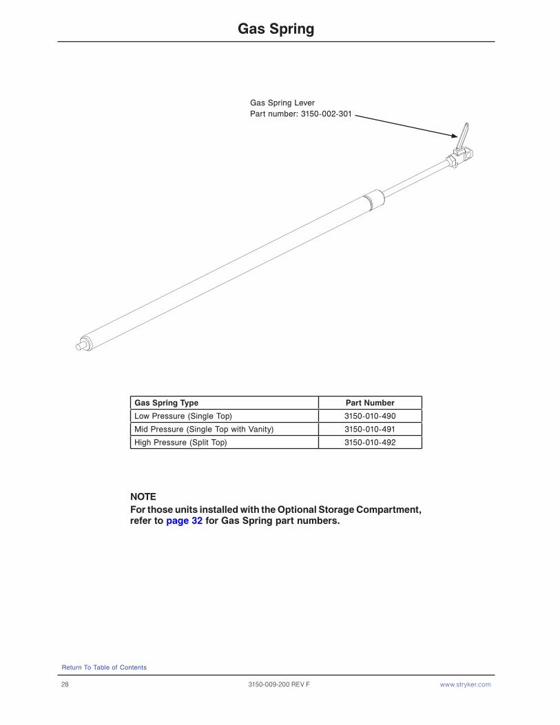
gas spring
gas spring Type part number
Low Pressure (Single Top) 3150-010-490
Mid Pressure (Single Top with Vanity) 3150-010-491
High Pressure (Split Top) 3150-010-492
nOTeFor those units installed with the Optional storage Compartment, refer to page 32 for gas spring part numbers.
Gas Spring LeverPart number: 3150-002-301
Return To Table of Contents

www.stryker.com 3150-009-200 REV F 29
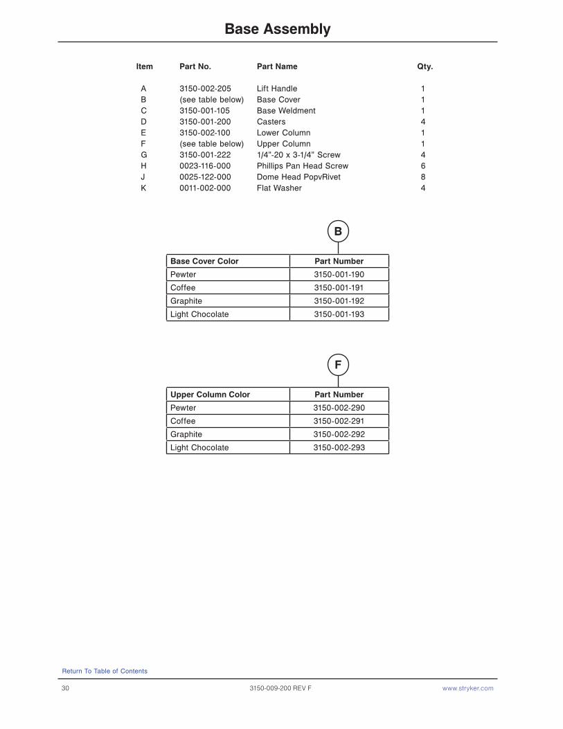
base assembly
For Reference Only: Part Number 3150-001-000
B
C
D
JHJ
HJ
D
J
D
H
D
E
FA
G
K
Return To Table of Contents
30 3150-009-200 REV F www.stryker.com
base assembly
Item part no. part name Qty.
A 3150-002-205 Lift Handle 1B (see table below) Base Cover 1C 3150-001-105 Base Weldment 1D 3150-001-200 Casters 4E 3150-002-100 Lower Column 1F (see table below) Upper Column 1G 3150-001-222 1/4”-20 x 3-1/4” Screw 4H 0023-116-000 Phillips Pan Head Screw 6J 0025-122-000 Dome Head PopvRivet 8K 0011-002-000 Flat Washer 4
base Cover Color part number
Pewter 3150-001-190
Coffee 3150-001-191
Graphite 3150-001-192
Light Chocolate 3150-001-193
Upper Column Color part number
Pewter 3150-002-290
Coffee 3150-002-291
Graphite 3150-002-292
Light Chocolate 3150-002-293
b
F
Return To Table of Contents
www.stryker.com 3150-009-200 REV F 31
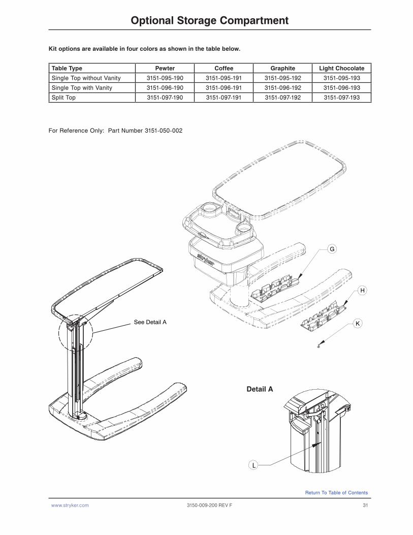
Optional storage Compartment
Table Type pewter Coffee graphite light Chocolate
Single Top without Vanity 3151-095-190 3151-095-191 3151-095-192 3151-095-193
Single Top with Vanity 3151-096-190 3151-096-191 3151-096-192 3151-096-193
Split Top 3151-097-190 3151-097-191 3151-097-192 3151-097-193
kit options are available in four colors as shown in the table below.
For Reference Only: Part Number 3151-050-002
K
H
G
See Detail A
L
detail a
Return To Table of Contents
32 3150-009-200 REV F www.stryker.com
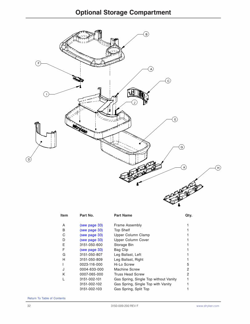
Item part no. part name Qty.
A (see page 33) Frame Assembly 1B (see page 33) Top Shelf 1C (see page 33) Upper Column Clamp 1D (see page 33) Upper Column Cover 1E 3151-050-600 Storage Bin 1F (see page 33) Bag Clip 1G 3151-050-807 Leg Ballast, Left 1H 3151-050-809 Leg Ballast, Right 1I 0023-116-000 Hi-Lo Screw 5J 0004-633-000 Machine Screw 2K 0007-065-000 Truss Head Screw 2L 3151-002-101 Gas Spring, Single Top without Vanity 1 3151-002-102 Gas Spring, Single Top with Vanity 1 3151-002-103 Gas Spring, Split Top 1
Optional storage Compartment
B
A
C
E
G
K H
J
I
F
D
Return To Table of Contents

www.stryker.com 3150-009-200 REV F 33
Item description Qty. pewter Coffee graphite light Chocolate
A Frame Assembly 1 3151-050-390 3151-050-391 3151-050-392 3151-050-393
B Top Shelf 1 3151-050-190 3151-050-191 3151-050-192 3151-050-193
C Column Clamp 1 3151-050-490 3151-050-491 3151-050-492 3151-050-493
D Column Cover 1 3151-050-790 3151-050-791 3151-050-792 3151-050-793
F Bag Clip 1 3151-050-590 3151-050-591 3151-050-592 3151-050-593
Optional storage Compartment
COlOr OpTIOns
Return To Table of Contents

34 3150-009-200 REV F www.stryker.com
warranty
Return To Table of Contents
Stryker Medical stands behind the craftsmanship of our products. Providing our customers quality products is our mission, and we pledge to do everything we can to quickly resolve any problems encountered within the terms of the warranties listed below. These warranties apply only to products manufactured after January 1, 2008.
One year warranTy
Stryker warrants the following products for one year under normal use and proper care. For one year from date of shipment, Stryker will repair or, at our option, replace defective merchandise free of charge (parts, labor and shipping included).
Tru-Fit® Overbed Tables.•Bedside Stands (*Note: LIFETIME WARRANTY on metal drawer frames and glides).•Maternity Furniture.•Flexsteel Hospital Recliner.•
The One Year warranty listed above are void in cases of modifications, misuse, improper assembly or maintenance, accidents, damage caused by a carrier other than Stryker Medical, and the use of customer’s own material.
Stryker makes no other warranty or representation, either expressed or implied, except as set forth herein. There is no warranty of merchantability and there are no warranties of fitness for any particular purpose. In no event shall Stryker be liable hereunder for incidental or consequential damages arising from or in any manner related to sales or use of any such equipment.
TO ObTaIn parTs and servICeStryker products are supported by a nationwide network of dedicated Stryker Field Service Representatives. These representatives are factory trained, available locally, and carry a substantial spare parts inventory to minimize repair time. Simply call your local representative, or call Stryker Customer Service USA at 1-800-327−0770.
reTUrn aUThOrIzaTIOnMerchandise cannot be returned without approval from the Stryker Customer Service Department. An authorization number will be provided which must be printed on the returned merchandise. Stryker reserves the right to charge ship-ping and restocking fees on returned items. special, modified, or discontinued, items not subject to return.
daMaged MerChandIseICC Regulations require that claims for damaged merchandise must be made with the carrier within fifteen (15) days of receipt of merchandise. do not accept damaged shipments unless such damage is noted on the delivery receipt at the time of receipt. Upon prompt notification, Stryker will file a freight claim with the appropriate carrier for damages incurred. Claim will be limited in amount to the actual replacement cost. In the event that this information is not received by Stryker within the fifteen (15) day period following the delivery of the merchandise, or the damage was not noted on the delivery receipt at the time of receipt, the customer will be responsible for payment of the original invoice in full. Claims for any short shipment must be made within thirty (30) days of invoice.
InTernaTIOnal warranTy ClaUseThis warranty reflects U.S. domestic policy. Warranty outside the U.S. may vary by country. Please contact your local Stryker Medical representative for additional information.

www.stryker.com 3150-009-200 REV F 35
warranty
servICe COnTraCT COverage
Stryker has developed a comprehensive program of service contract options designed to keep your equipment operating at peak performance at the same time it eliminates unexpected costs. We recommend that these programs be activated before the expiration of the new product warranty to eliminate the potential of additional equipment upgrade charges.
a service Contract helps to:
Ensure equipment reliability•Stabilize maintenance budgets•Diminish downtime•Establish documentation for JCAHO•Increase product life•Enhance trade-in value•Address risk management and safety•
servICe COnTraCT prOgraMs
Stryker offers the following service contract programs:
service agreement Options * gold silver parts labor pM
Annually scheduled preventative maintenance X X
All parts X X X
All labor and travel X X X
Unlimited emergency service calls X X X
Priority one contact: two hour phone response X X X X
Most repairs completed within 3 days X X X
JCAHO documentation X X X X
On-site record of PM & emergency service X X
Factory-trained Stryker service technician X X X X
Stryker authorized parts used X X X X X
Service during regular business hours (8−5) X X X X X
* Does not include maintenance due to abuse or for any disposable items. Stryker reserves the right to change options without notice.
Stryker Medical also offers personalized service contracts.Pricing is determined by age, location, model and condition of product.
For more information on our service contracts, please call your local representative.
Return To Table of Contents


Stryker Medical3800 E. Centre Ave.,Portage, Michigan49002
european representativeStryker FranceZAC Satolas Green PusignanAv. De Satolas Green69881 MEYZIEU CedexFrance
eC rep
2008/01 3150-009-200 REV F www.stryker.com