Embed Size (px)
Citation preview
W. W. Patterson Company3 Riversea Road
Pittsburgh, PA 15233Phone: 800-322-2018
FAX: 412-322-2785
OPERATIONS/PARTS MANUALFOR
PATTERSON'SMODEL # WWP30E-5-10
ELECTRIC WINCH.
Please fill in the following blanks and then keep this manual in a safe and convenient location.When calling with either questions or replacement part needs, always refer to the Winch Model,Part Number and Serial Number.
WINCH PART #: 6250-NC WINCH SERIAL #: __________________
MOTOR MFG.: _____________________ MOTOR SERIAL #: __________________
BRAKE SERIAL #: _________________ DATE PURCHASED: ________________
DISTRIBUTOR INFORMATION
NAME: _________________________________________________________________
ADDRESS: ______________________________________________________________
CITY: _____________________________ STATE: ___________ ZIP: ____________
PHONE: ___________________________ FAX: _____________________________
200301176250NC

IMPORTANT!Prior to installing and operating the winch, please read this manual thoroughlyand carefully. Keep this manual and all other instructions accessible at all times.
Although this manual will help you become familiarized with the operatingprocedures for the winch, it is by no means a substitute for proper training and thesafe use of winches, barge rigging and other marine equipment. Because ownersand operators are solely responsible for determining whether a particular usageis acceptable, only individuals trained in the proper use of winches, barge riggingand other marine equipment should operate winches.
The typical operational environment of winches includes very high forces, and thepotential hazards associated with these forces should not be underestimated.Improper installation or misuse of the winch may result in injury to persons orcause equipment failure or damage.
ALWAYS OBSERVE THESE BASIC SAFETYPRECAUTIONS:
• To reduce potential of electrical shock or other injury, turn off and lock out or tagout power source before initiating any maintenance or repairs.
• Keep all fingers, loose clothing and any foreign objects away from winch while inoperation.
• During operation of the winch, always remain to the side of the winch, slightlybehind the gear motor.
• Never operate the winch from the front or when bystanders are in front of it.• Operators and bystanders should stay clear of any load and the wire rope while the
winch is operating.• Under no circumstances, should any winch be used to move, raise or lower a
person(s) or equipment.• Do not operate the winch unless you have a firm stance on a non-slippery surface.• Do not apply tension to the winch unless there are at least four complete wraps of rope
on the drum.• Motorized operation of the winch with the hand crank engaged in the Motor Shaft is
improper and a misuse of the winch. Instead, the hand crank should be stored in itsproper place prior to motorized operation.
• Inspect the winch carefully at least once a month for worn gears and pawls, crackedwelds, and other damaged parts. If any worn, cracked or damaged parts are found, stopuse immediately and remove the winch from service until all appropriate repairs arecompletely made.
3
1.1.1.1.1. INST INST INST INST INSTALLAALLAALLAALLAALLA TIONTIONTIONTIONTION
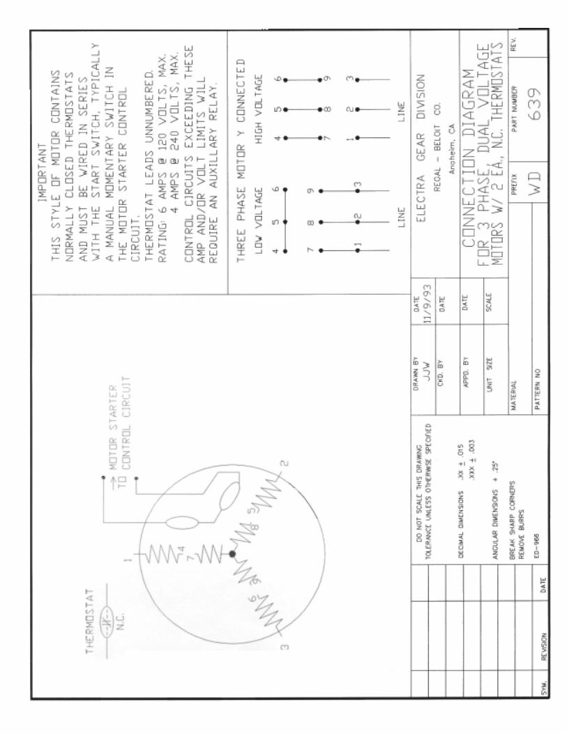
THERMOSTATLEADS
ELECTRA-GEARMOTORS ONLY
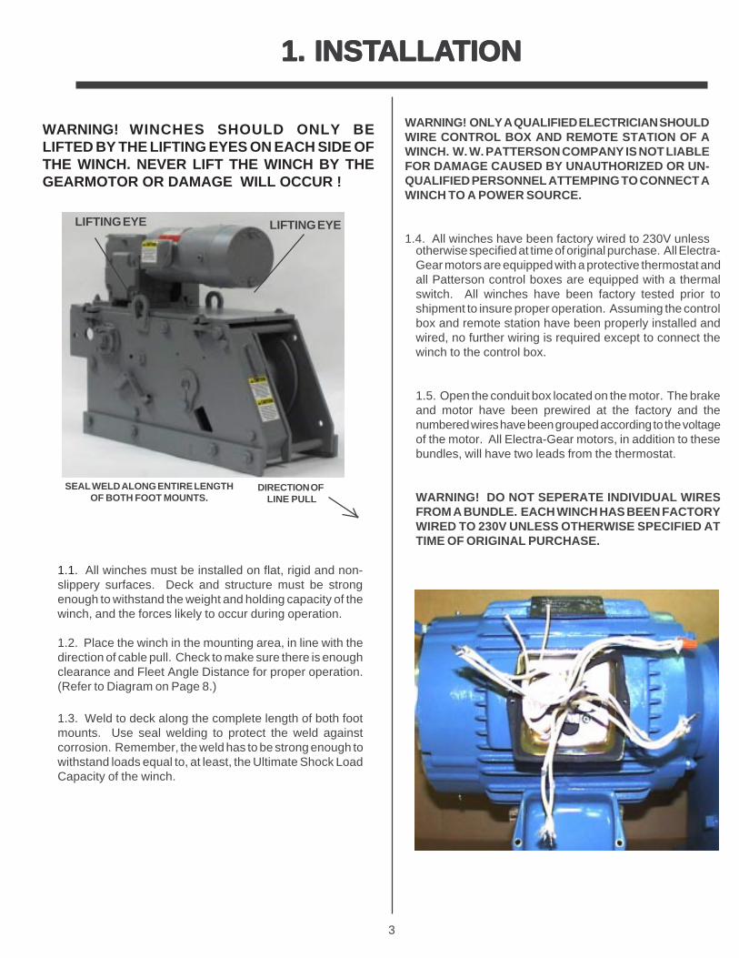
WARNING! WINCHES SHOULD ONLY BELIFTED BY THE LIFTING EYES ON EACH SIDE OFTHE WINCH. NEVER LIFT THE WINCH BY THEGEARMOTOR OR DAMAGE WILL OCCUR !
1.1. All winches must be installed on flat, rigid and non-slippery surfaces. Deck and structure must be strongenough to withstand the weight and holding capacity of thewinch, and the forces likely to occur during operation.
1.2. Place the winch in the mounting area, in line with thedirection of cable pull. Check to make sure there is enoughclearance and Fleet Angle Distance for proper operation.(Refer to Diagram on Page 8.)
1.3. Weld to deck along the complete length of both footmounts. Use seal welding to protect the weld againstcorrosion. Remember, the weld has to be strong enough towithstand loads equal to, at least, the Ultimate Shock LoadCapacity of the winch.
WARNING! ONLY A QUALIFIED ELECTRICIAN SHOULDWIRE CONTROL BOX AND REMOTE STATION OF AWINCH. W. W. PATTERSON COMPANY IS NOT LIABLEFOR DAMAGE CAUSED BY UNAUTHORIZED OR UN-QUALIFIED PERSONNEL ATTEMPING TO CONNECT AWINCH TO A POWER SOURCE.
1.4. All winches have been factory wired to 230V unless
THLE
ELS
otherwise specified at time of original purchase. All Electra-Gear motors are equipped with a protective thermostat andall Patterson control boxes are equipped with a thermalswitch. All winches have been factory tested prior toshipment to insure proper operation. Assuming the controlbox and remote station have been properly installed andwired, no further wiring is required except to connect thewinch to the control box.
1.5. Open the conduit box located on the motor. The brakeand motor have been prewired at the factory and thenumbered wires have been grouped according to the voltageof the motor. All Electra-Gear motors, in addition to thesebundles, will have two leads from the thermostat.
WARNING! DO NOT SEPERATE INDIVIDUAL WIRESFROM A BUNDLE. EACH WINCH HAS BEEN FACTORYWIRED TO 230V UNLESS OTHERWISE SPECIFIED ATTIME OF ORIGINAL PURCHASE.
SEAL WELD ALONG ENTIRE LENGTHOF BOTH FOOT MOUNTS.
DIRECTION OF LINE PULL
LIFTING EYELIFTING EYE
4
1.1.1.1.1. INST INST INST INST INSTALLAALLAALLAALLAALLA TION (Cont'd.)TION (Cont'd.)TION (Cont'd.)TION (Cont'd.)TION (Cont'd.)
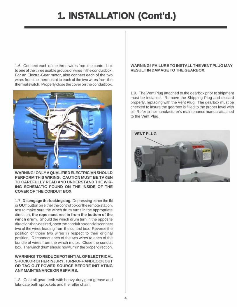
1.6. Connect each of the three wires from the control boxto one of the three usable groups of wires in the conduit box.For an Electra-Gear motor, also connect each of the twowires from the thermostat to each of the two wires from thethermal switch. Properly close the cover on the conduit box.
WARNING! ONLY A QUALIFIED ELECTRICIAN SHOULDPERFORM THIS WIRING. CAUTION MUST BE TAKENTO CAREFULLY READ AND UNDERSTAND THE WIR-ING SCHEMATIC FOUND ON THE INSIDE OF THECOVER OF THE CONDUIT BOX.
1.7. Disengage the locking dog. Depressing either the INor OUT button on either the control box or the remote station,test to make sure the winch drum turns in the appropriatedirection; the rope must reel in from the bottom of thewinch drum . Should the winch drum turn in the oppositedirection than desired, open the conduit box and disconnecttwo of the wires leading from the control box. Reverse theposition of those two wires in respect to their originalposition. Reconnect each of the two wires to each of thebundle of wires from the winch motor. Close the conduitbox. The winch drum should now turn in the proper direction.
WARNING! TO REDUCE POTENTIAL OF ELECTRICALSHOCK OR OTHER INJURY, TURN OFF AND LOCK OUTOR TAG OUT POWER SOURCE BEFORE INITIATINGANY MAINTENANCE OR REPAIRS.
1.8. Coat all gear teeth with heavy-duty gear grease andlubricate both sprockets and the roller chain.
WARNING! FAILURE TO INSTALL THE VENT PLUG MAYRESULT IN DAMAGE TO THE GEARBOX.
1.9. The Vent Plug attached to the gearbox prior to shipmentmust be installed. Remove the Shipping Plug and discardproperly, replacing with the Vent Plug. The gearbox must bechecked to insure the gearbox is filled to the proper level withoil. Refer to the manufacturer's maintenance manual attachedto the Vent Plug.
VENT PLUG
5
2. ATTACHING THE WIRE ROPE
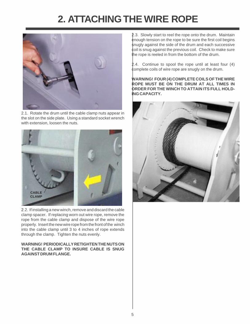
2.1. Rotate the drum until the cable clamp nuts appear inthe slot on the side plate. Using a standard socket wrenchwith extension, loosen the nuts.
2.3. Slowly start to reel the rope onto the drum. Maintainenough tension on the rope to be sure the first coil beginssnugly against the side of the drum and each successivecoil is snug against the previous coil. Check to make surethe rope is reeled in from the bottom of the drum.
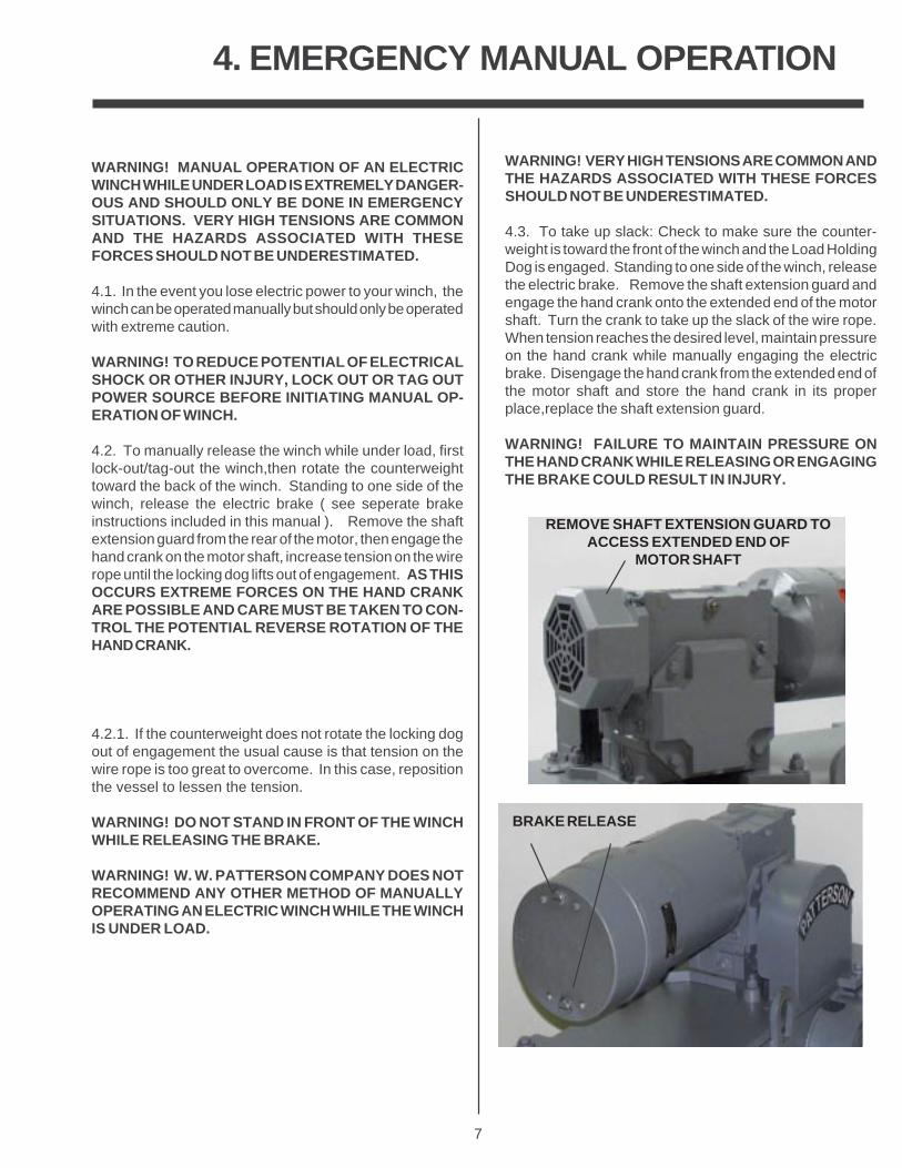
2.4. Continue to spool the rope until at least four (4)complete coils of wire rope are snugly on the drum.
WARNING! FOUR (4) COMPLETE COILS OF THE WIREROPE MUST BE ON THE DRUM AT ALL TIMES INORDER FOR THE WINCH TO ATTAIN ITS FULL HOLD-ING CAPACITY.
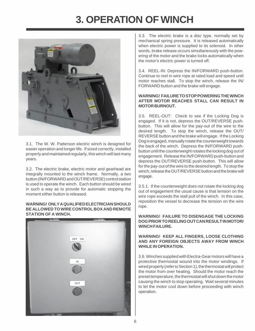
2.2. If installing a new winch, remove and discard the cableclamp spacer. If replacing worn out wire rope, remove therope from the cable clamp and dispose of the wire ropeproperly. Insert the new wire rope from the front of the winchinto the cable clamp until 3 to 4 inches of rope extendsthrough the clamp. Tighten the nuts evenly.
WARNING! PERIODICALLY RETIGHTEN THE NUTS ONTHE CABLE CLAMP TO INSURE CABLE IS SNUGAGAINST DRUM FLANGE.
CABLECLAMP
6
3. OPERATION OF WINCH3.3. The electric brake is a disc type, normally set bymechanical spring pressure. It is released automaticallywhen electric power is supplied to its solenoid. In otherwords, brake release occurs simultaneously with the pow-ering of the motor and the brake locks automatically whenthe motor's electric power is turned off.
3.4. REEL-IN: Depress the IN/FORWARD push-button.Continue to reel in wire rope at rated load and speed untilmotor reaches stall. To stop the winch, release the IN/FORWARD button and the brake will engage.
WARNING! FAILURE TO STOP POWERING THE WINCHAFTER MOTOR REACHES STALL CAN RESULT INMOTOR BURNOUT.
3.5. REEL-OUT: Check to see if the Locking Dog isengaged. If it is not, depress the OUT/REVERSE push-button. This will allow for the pay-out of the wire to thedesired length. To stop the winch, release the OUT/REVERSE button and the brake will engage. If the LockingDog is engaged, manually rotate the counterweight towardsthe back of the winch. Depress the IN/FORWARD push-button until the counterweight rotates the locking dog out ofengagement. Release the IN/FORWARD push-button anddepress the OUT/REVERSE push-button. This will allowfor the pay-out of the wire to the desired length. To stop thewinch, release the OUT/REVERSE button and the brake willengage.
3.5.1. If the counterweight does not rotate the locking dogout of engagement the usual cause is that tension on thewire rope exceeds the stall pull of the winch. In this case,reposition the vessel to decrease the tension on the wirerope.
WARNING! FAILURE TO DISENGAGE THE LOCKINGDOG PRIOR TO REELING OUT CAN RESULT IN MOTOR/WINCH FAILURE.
WARNING! KEEP ALL FINGERS, LOOSE CLOTHINGAND ANY FOREIGN OBJECTS AWAY FROM WINCHWHILE IN OPERATION.
3.6. Winches supplied with Electra-Gear motors will have aprotective thermostat wound into the motor windings. Ifwired properly (refer to Section 1), the thermostat will protectthe motor from over heating. Should the motor reach thepreset temperature, the thermostat will shut down the motorcausing the winch to stop operating. Wait several minutesto let the motor cool down before proceeding with winchoperation.
OFF ON
IN
OUT
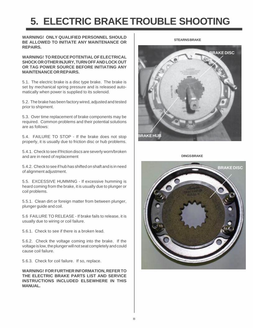
3.1. The W. W. Patterson electric winch is designed foreasier operation and longer life. If sized correctly, installedproperly and maintained regularly, this winch will last manyyears.
3.2. The electric brake, electric motor and gearhead areintegrally mounted to the winch frame. Normally, a twobutton (IN/FORWARD and OUT/REVERSE) control stationis used to operate the winch. Each button should be wiredin such a way as to provide for automatic stopping themoment either button is released.
WARNING! ONLY A QUALIFIED ELECTRICIAN SHOULDBE ALLOWED TO WIRE CONTROL BOX AND REMOTESTATION OF A WINCH.
7
4. EMERGENCY MANUAL OPERATION
WARNING! MANUAL OPERATION OF AN ELECTRICWINCH WHILE UNDER LOAD IS EXTREMELY DANGER-OUS AND SHOULD ONLY BE DONE IN EMERGENCYSITUATIONS. VERY HIGH TENSIONS ARE COMMONAND THE HAZARDS ASSOCIATED WITH THESEFORCES SHOULD NOT BE UNDERESTIMATED.
4.1. In the event you lose electric power to your winch, thewinch can be operated manually but should only be operatedwith extreme caution.
WARNING! TO REDUCE POTENTIAL OF ELECTRICALSHOCK OR OTHER INJURY, LOCK OUT OR TAG OUTPOWER SOURCE BEFORE INITIATING MANUAL OP-ERATION OF WINCH.
4.2. To manually release the winch while under load, firstlock-out/tag-out the winch,then rotate the counterweighttoward the back of the winch. Standing to one side of thewinch, release the electric brake ( see seperate brakeinstructions included in this manual ). Remove the shaftextension guard from the rear of the motor, then engage thehand crank on the motor shaft, increase tension on the wirerope until the locking dog lifts out of engagement. AS THISOCCURS EXTREME FORCES ON THE HAND CRANKARE POSSIBLE AND CARE MUST BE TAKEN TO CON-TROL THE POTENTIAL REVERSE ROTATION OF THEHAND CRANK.
4.2.1. If the counterweight does not rotate the locking dogout of engagement the usual cause is that tension on thewire rope is too great to overcome. In this case, repositionthe vessel to lessen the tension.
WARNING! DO NOT STAND IN FRONT OF THE WINCHWHILE RELEASING THE BRAKE.
WARNING! W. W. PATTERSON COMPANY DOES NOTRECOMMEND ANY OTHER METHOD OF MANUALLYOPERATING AN ELECTRIC WINCH WHILE THE WINCHIS UNDER LOAD.
WARNING! VERY HIGH TENSIONS ARE COMMON ANDTHE HAZARDS ASSOCIATED WITH THESE FORCESSHOULD NOT BE UNDERESTIMATED.
4.3. To take up slack: Check to make sure the counter-weight is toward the front of the winch and the Load HoldingDog is engaged. Standing to one side of the winch, releasethe electric brake. Remove the shaft extension guard andengage the hand crank onto the extended end of the motorshaft. Turn the crank to take up the slack of the wire rope.When tension reaches the desired level, maintain pressureon the hand crank while manually engaging the electricbrake. Disengage the hand crank from the extended end ofthe motor shaft and store the hand crank in its properplace,replace the shaft extension guard.
WARNING! FAILURE TO MAINTAIN PRESSURE ONTHE HAND CRANK WHILE RELEASING OR ENGAGINGTHE BRAKE COULD RESULT IN INJURY.
REMOVE SHAFT EXTENSION GUARD TOACCESS EXTENDED END OF
MOTOR SHAFT
BRAKE RELEASE
8
5. ELECTRIC BRAKE TROUBLE SHOOTINGWARNING! ONLY QUALIFIED PERSONNEL SHOULDBE ALLOWED TO INITIATE ANY MAINTENANCE ORREPAIRS.
WARNING! TO REDUCE POTENTIAL OF ELECTRICALSHOCK OR OTHER INJURY, TURN OFF AND LOCK OUTOR TAG POWER SOURCE BEFORE INITIATING ANYMAINTENANCE OR REPAIRS.
5.1. The electric brake is a disc type brake. The brake isset by mechanical spring pressure and is released auto-matically when power is supplied to its solenoid.
5.2. The brake has been factory wired, adjusted and testedprior to shipment.
5.3. Over time replacement of brake components may berequired. Common problems and their potential solutionsare as follows:
5.4. FAILURE TO STOP - If the brake does not stopproperly, it is usually due to friction disc or hub problems.
5.4.1. Check to see if friction discs are severly worn/brokenand are in need of replacement
5.4.2. Check to see if hub has shifted on shaft and is in needof alignment adjustment.
5.5. EXCESSIVE HUMMING - If excessive humming isheard coming from the brake, it is usually due to plunger orcoil problems.
5.5.1. Clean dirt or foreign matter from between plunger,plunger guide and coil.
5.6 FAILURE TO RELEASE - If brake fails to release, it isusually due to wiring or coil failure.
5.6.1. Check to see if there is a broken lead.
5.6.2. Check the voltage coming into the brake. If thevoltage is low, the plunger will not seat completely and couldcause coil failure.
5.6.3. Check for coil failure. If so, replace.
WARNING! FOR FURTHER INFORMATION, REFER TOTHE ELECTRIC BRAKE PARTS LIST AND SERVICEINSTRUCTIONS INCLUDED ELSEWHERE IN THISMANUAL.
BRAKE LEADS
SOLENOID
PLUNGERPLUNGER GUIDE
BRAKE DISC
BRAKE HUB
BRAKE DISC
STEARNS BRAKE
DINGS BRAKE
9
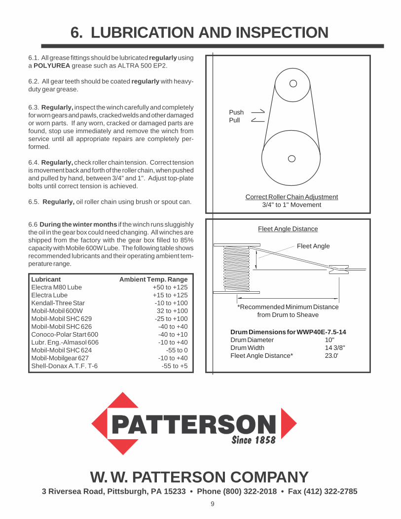
6. LUBRICATION AND INSPECTION
W. W. PATTERSON COMPANY3 Riversea Road, Pittsburgh, PA 15233 • Phone (800) 322-2018 • Fax (412) 322-2785
6.1. All grease fittings should be lubricated regularly usinga POLYUREA grease such as ALTRA 500 EP2.
6.2. All gear teeth should be coated regularly with heavy-duty gear grease.
6.3. Regularly, inspect the winch carefully and completelyfor worn gears and pawls, cracked welds and other damagedor worn parts. If any worn, cracked or damaged parts arefound, stop use immediately and remove the winch fromservice until all appropriate repairs are completely per-formed.
6.4. Regularly, check roller chain tension. Correct tensionis movement back and forth of the roller chain, when pushedand pulled by hand, between 3/4" and 1". Adjust top-platebolts until correct tension is achieved.
6.5. Regularly, oil roller chain using brush or spout can.
PushPull
Correct Roller Chain Adjustment3/4" to 1" Movement
6.6 During the winter months if the winch runs sluggishlythe oil in the gear box could need changing. All winches areshipped from the factory with the gear box filled to 85%capacity with Mobile 600W Lube. The following table showsrecommended lubricants and their operating ambient tem-perature range.
Lubricant Ambient Temp. RangeElectra M80 Lube +50 to +125Electra Lube +15 to +125Kendall-Three Star -10 to +100Mobil-Mobil 600W 32 to +100Mobil-Mobil SHC 629 -25 to +100Mobil-Mobil SHC 626 -40 to +40Conoco-Polar Start 600 -40 to +10Lubr. Eng.-Almasol 606 -10 to +40Mobil-Mobil SHC 624 -55 to 0Mobil-Mobilgear 627 -10 to +40Shell-Donax A.T.F. T-6 -55 to +5
Fleet Angle Distance
Fleet Angle
*Recommended Minimum Distancefrom Drum to Sheave
Drum Dimensions for WWP40E-7.5-14Drum Diameter 10"Drum Width 14 3/8"Fleet Angle Distance* 23.0'
10
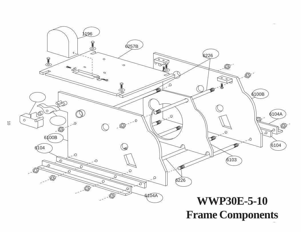
WWP30E-5-10Frame Components
6104
6104A
6100B
6226
6103
6257B
1196
6100B
6104
6104A
6226
11
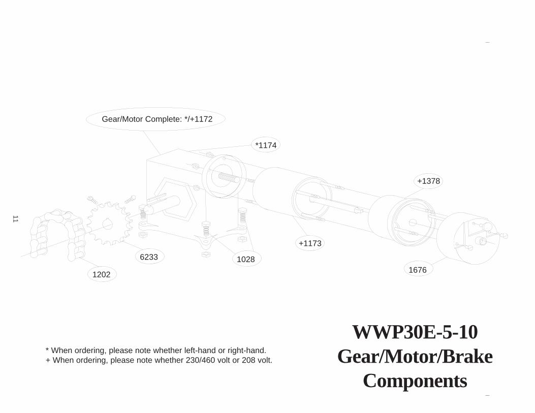
WWP30E-5-10Gear/Motor/Brake
Components
1676
+1378
+1173
*1174
1028
Gear/Motor Complete: */+1172
6233
1202
* When ordering, please note whether left-hand or right-hand.+ When ordering, please note whether 230/460 volt or 208 volt.
12
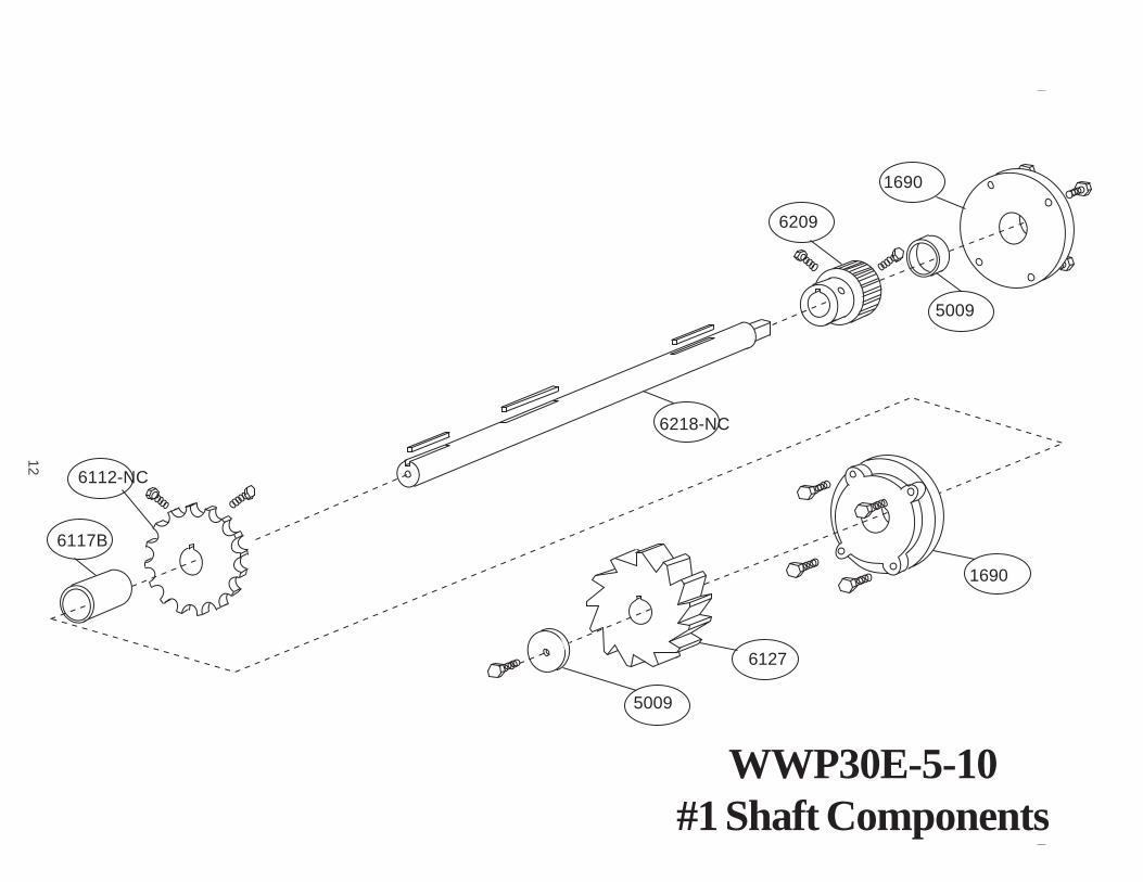
WWP30E-5-10#1 Shaft Components
6218-NC
5009
6127
1690
6209
1690
5009
6112-NC
6117B
13
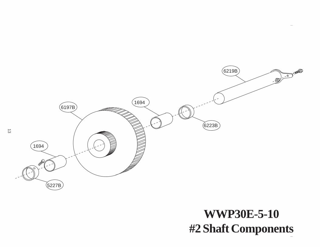
WWP30E-5-10#2 Shaft Components
6219B
6223B
16946197B
1694
5227B
14
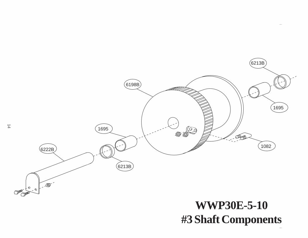
WWP30E-5-10#3 Shaft Components
6213B
1695
1082
6198B
1695
6213B
6222B

15
Frame ComponentsQUANTITY DESCRIPTION PART NUMBER
2 Side Plate 6100B1 Rope Guard 61031 Locking Dog 60471 Counter Weight 60452 Foot Mount 61042 Angle Foot Mount 6104A1 Motor Base Plate 6257B7 Seperator Tube/Tie Rod 62261 Sprocket Guard 1196
Gear/Motor/Brake ComponentsQUANTITY DESCRIPTION PART NUMBER
1 Gear/Motor Complete */+ 11661 Motor Only+ 11671 Gear Box Only* 11681 Motor Sprocket 60561 Roller Chain 12054 Tie Down Bolts 10281 Brake Cover 16761 Brake - Complete **/+ 1379
* When ordering, please note whether left-hand or right-hand.** To order individual Stearns Brake components, refer to Stearns' Parts List includedelsewhere in this manual.+ When ordering, please note whether 230/460 volt or 208 volt.
WWP30E-5-10 WINCH PARTS LIST
16
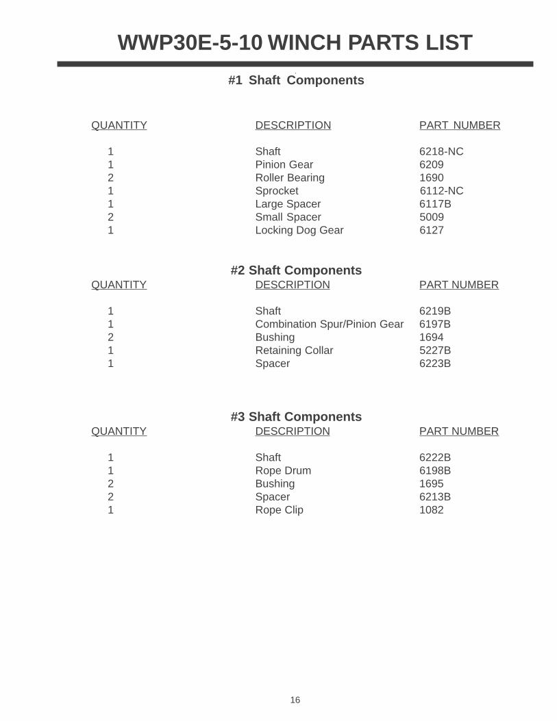
WWP30E-5-10 WINCH PARTS LIST
#1 Shaft Components
QUANTITY DESCRIPTION PART NUMBER
1 Shaft 6218-NC1 Pinion Gear 62092 Roller Bearing 16901 Sprocket 6112-NC1 Large Spacer 6117B2 Small Spacer 50091 Locking Dog Gear 6127
#2 Shaft ComponentsQUANTITY DESCRIPTION PART NUMBER
1 Shaft 6219B1 Combination Spur/Pinion Gear 6197B2 Bushing 16941 Retaining Collar 5227B1 Spacer 6223B
#3 Shaft ComponentsQUANTITY DESCRIPTION PART NUMBER
1 Shaft 6222B1 Rope Drum 6198B2 Bushing 16952 Spacer 6213B1 Rope Clip 1082