Embed Size (px)
Citation preview

48-1-21 : 1
6- OPERATION MANUAL FOR MACHINE 48 VERSION 48-1-21 This document is made up of the following sections: COMPULSORY READING SECTIONS FOR USERS 6.1 - Essential parameter programming for initial machine operation. 6.2 - Working process COMPULSORY READING SECTIONS FOR MAINTENANCE PERSONNEL
6.3 - TEST processes. 6.4 - Temperature adjustment process. 6.5 - Secret pages. 6.6 - Key summary. 6.7 - Alarm list. COMPULSORY READING SECTIONS ONLY FOR QUALIFIED PERSONNEL 6.8 - Essential timing and parameter programming for initial machine operation. 6.9 - Function diagrams.

48-1-21 : 2
6.1 - ESSENTIAL PARAMETER PROGRAMMING TO ALLOW MACHINE OPERATION The following screen appears on connection to the electrical power supply:
indicating the program version of the machine. Shortly afterwards the main screen appears: This page gives access to different machine options. 6.1.1 - PROGRAMMING OF TEMPERATURE PARAMETERS By pressing this key: the following screen will appear:

48-1-21 : 3
By using the cursor keys ( )( ) to move around the page it is possible to select the field that we wish to modify. By using the cursor keys ( ≈ )( ≡ ) we ca move to the next programming page. The selected field will be highlighted on a white background with black letters. Once the required field is selected, we can introduce the new value, after which the (M) key is pressed to validate the entered data. Once all data has been entered in this way, pressing the escape key (ESC) will save the data to the non volatile memory (EEPROM). Whilst data is being saved, the following screen is displayed:

48-1-21 : 4
6.1.1.1 - DESCRIPTION OF PARAMETERS. The temperature value is programmed according to the required working temperature for each zone.
Changing this parameter programs the time interval between temperature conversions.
When this value is missing there is a proportional resistance connection, the greater the difference between actual and programmed temperature, the greater the duration of the resistance connection. When the difference between actual and programmed temperature is lower, the shorter is the duration of the resistance connection The proportional duration of connection/disconnection of resistor is shared with respect to the previously programmed temperature reading interval,
If the temperature reaches a value within the margins (programmed zone - deviation alarm margin) and (programmed zone + deviation alarm margin) the out of range temperature alarm is not triggered. NOTE: Once the electrical supply is connected the heating process is initiated progressively for several minutes in order to protect the resistance units.

48-1-21 : 5
6.1.2 - TIMINGS PROGRAMMING. By pressing this key: the following screen will appear:
By using the cursor keys ( )( ) we can move around the page to select the field that we wish to modify. The selected field will be highlighted with black letters on a white background. Once the required field is selected, we can introduce the new value, after which the (M) key is pressed to validate the entered data. Once all data has been entered in this way, pressing the escape key (ESC) will save the data to the non volatile memory (EEPROM). Whilst data is being saved the following screen is displayed:

48-1-21 : 6
6.1.2.1 - DESCRIPTION OF TIMINGS.
It is necessary to program the bag length (mm) we wish to produce. (This value must be programmed with any of the measuring modes selected)
When working in SPOT mode the film dosing motor will stop when the corresponding SPOT on the film is detected. Letters and drawings that may be printed on the film may confuse the SPOT detector, thereby provoking a false stoppage. We program this value in order to avoid this problem, so that the SPOT detection is disabled until the SPOT is approached, the SPOT zone being identifiable as a function of bag length (For example: Bag length 450mm, Length before SPOT 20mm, indicates that detection will not be activated until bag travel exceeds 430mm (450-20). (This timing only applies to the SPOT dosing modes)
This value comes into play when the length of film fed is equivalent to the theoretical length but without the SPOT having been detected. Once the length programmed here has been fed without the SPOT having been detected, the motor will be stopped. (This timing only applies to the SPOT dosing modes)
When the input conveyor has stopped thus indicating that a packet has been sent, this timing is activated and allows time for the product to fall completely into the bag. Once this time has passed the bag is considered to have finished charging with product.
This timer initiates when a signal from the weigh cell is received thus indicating that a packet has been sent. On completion of this time the input conveyor receives a signal to indicate that the packet is on the conveyor. This feature is employed when the machine is connected to a weighing cell that is shared with another packaging machine that requires a shorter TIME than the "48", in which case we increase the TIME to coincide with that of the "48".

48-1-21 : 7
These timings allow the exit conveyor vibration times to be programmed.
This timer is connected when the transfer process is initiated. When this time is completed the input conveyor is connected (If there is product on the conveyor). 6.1.3 – PROGRAMMING OF WORKING PARAMETERS. By pressing the (M) key we gain access to the programming section for the different options.
The cursor keys are activated allowing access to the options. By using the keys we can select the parameters that we wish to modify.
By using the keys we modify the option. To exit the working parameter programming mode, press the (M) key again. On initiating the process the following screen will appear:
The "STATIC WELDING" indicator appears, which is the default option. This parameter cannot be modified from this point. It can only be modified in machine configuration given that such changes also imply a considerable amount of mechanical modification.

48-1-21 : 8
6.1.3.1 – EXIT CONVEYOR SELECTION By pressing the right cursor key the following indication appears:
In this case we select that the exit conveyor rises and vibrates. By using the up & down cursor keys the rest of the options can be chosen.
In this case we chose that the exit conveyor rises and SHALL NOT vibrate.
In this case the exit conveyor is not selected. 6.1.3.2 - ELEVATING PLATFORM SELECTION PROCESS By pressing the right cursor key the following indication appears:
In this case we select the elevating platform option. By using the up & down cursor keys, the rest of the options can be chosen.

48-1-21 : 9
In this case the elevating platform option is NOT selected. 6.1.3.3 - HANDLE / DIE SELECTION PROCESS By pressing the right cursor key the following indication appears:
In this case the option YES HANDLE is selected. By using the up & down cursor keys the rest of the options can be selected. The following screen will appear first:
A password is required to make changes given that this selection depends on a mechanical implementation, thereby avoiding accidental changes. The password is: 387999 Once the password is entered, the following screen appears:
In this case the DIE option is selected.
48-1-21 : 10
In this case the NO HANDLE and NO DIE modes are selected. 6.1.3.4 – HEATING SELECTION. By pressing the right cursor key, the following indication appears:
In this case indicating that the heating is activated. By using the up & down cursor keys, the rest of the options can be selected.
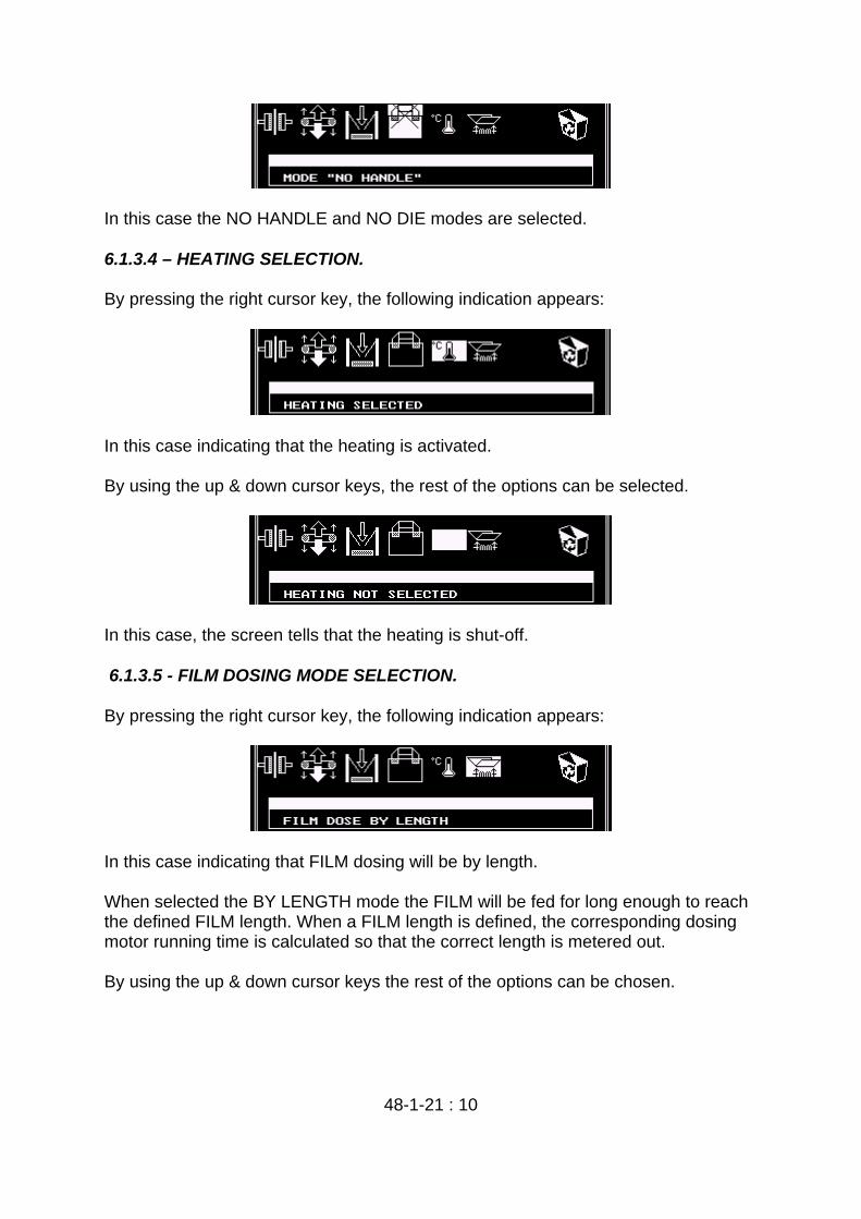
In this case, the screen tells that the heating is shut-off. 6.1.3.5 - FILM DOSING MODE SELECTION. By pressing the right cursor key, the following indication appears:
In this case indicating that FILM dosing will be by length. When selected the BY LENGTH mode the FILM will be fed for long enough to reach the defined FILM length. When a FILM length is defined, the corresponding dosing motor running time is calculated so that the correct length is metered out. By using the up & down cursor keys the rest of the options can be chosen.

48-1-21 : 11
In this case, the screen tells that FILM dosing will be by ONE SPOT If the ONE SPOT mode is selected, then by definition we will be using film that has regularly spaced black reference spots so that when the detector sees a SPOT, the FILM dosing motor stops.
In this case the screen informs that FILM dosing will be by TWO SPOTS. Selecting the TWO SPOT mode, by definition we are working with two FILM bands that will carry black reference spots at regular intervals. In this mode therefore, by means of energising and deenergising the brakes, an adjustment is aimed so that both SPOTS coincide. 6.1.3.6 - OPERATION WITH A LABELLER. By pressing the right cursor key the following indication appears on the screen if a labeller has been configured:
In this case the adhesive label option is selected. By using the up & down cursor keys the rest of the options can be chosen.
In this case the adhesive label option has NOT been selected. If the TRANSFER labeller is selected, the following signs appear:

48-1-21 : 12
TRANSFER label selected.
TRANSFER label NOT selected. When we have selected the labeller, an order can be given to make a label by pressing the [F3] key. Whilst the label is being produced the following indication appears: 6.1.3.7 - PHASE MEMORY ERASURE. By pressing the right cursor key, the following indication appears;
indicating that we are in the phase memory erasure option. By using the up & down cursor keys, phase erasure can be selected;
allowing us to confirm whether or not we wish to erase these memories. This could be necessary for the following reason: When the machine is operating, it records in the memories every time a phase is finished, so that if we stop the process and then re-start it the activated phases are considered to have been completed and the machine will not operate these phases.

48-1-21 : 13
If for some reason on stopping the process the bag is removed from one or more of the phases, if operation is resumed, the memorised phases will not be carried out although in fact they have not been completed. For this reason, if one bag is removed from one of the phases it is recommended that all bags be removed from the remaining phases and then the phase memories be erased. 6.1.4 - WORKING MODE SELECTION. By pressing the key: the automatic operation mode is selected. When the automatic operation mode is selected, the indicator will appear in the upper right of the screen indicating that there is an automatic communication with the weighing cell. If the AUTOMATIC indicator does not appear, the input request to the weighing cell will be manual, by pressing the key. 6.1.5 –TEMPERATURE ZONE DISPLAY.
By pressing the (F1) key it is possible to see the assignation of the different zones of the CB-48 by the display of the following screen:
The distribution of the machine thermocouples is indicated To exit this page, press any key.

48-1-21 : 14
The programmed temperatures will appear on the screen together with the actual temperature readings upon initiating heating control. Whilst the temperature is below the programmed temperature less the A deviation alarm margin @ the following indication appears: indicating the zones that are out of range. (Please note: Zone 7 is not shown to be out of range, due to the fact that this zone only operates when the DIE mode is selected) The following screen appears when the zones reach the programmed temperature: indicating that machine operation may commence.

48-1-21 : 15
6.1.6 – SAVE & RE-LOAD DESIGN PROCESS.
By pressing the (F9) key the following screen appears:
By using the (F1) key we can save the current machine data for the selected design. By using the (F2) key we can load the machine with previously saved data for a selected design. By using the cursor keys the design can be selected (0-9). To exit this section press the (ESC) key. 6.1.6.1 –DESIGN SAVING PROCESS.
By pressing the (F1) key the following screen will appear:

48-1-21 : 16
The first requirement is to record the description of the design that we wish to be saved. Numeric values can be entered directly by using the keypad. The desired character of alphanumeric values is selected by using the cursor keys, and may be entered in the memory by pressing the (M) key. Any character that has been introduced may be erased by pressing the (C) key . Once the corresponding description or comments have been entered,
by pressing the (ESC) key the data for this design are saved. 6.1.6.2 – DESIGN RE-LOAD PROCESS By pressing the (F2) key reloading of the selected design data can be carried out. If the selected design does not contain recorded data, an error message will appear and nothing else will happen. Exit the error screen by pressing the (ESC) key. If the control data (check-sum) of the saved data does not coincide with the figure calculated when the design was originally saved, an error message will be shown and nothing else will happen. Exit the error screen by pressing the (ESC) key. If none of these previously described problems occur, then the loading of the design data to the machine will proceed.
48-1-21 : 17
The description of the selected design will appear on the main screen to allow the operator to verify the selection.

48-1-21 : 17
6.2 - OPERATING PROCESS. Pressing RUN (MARCHA) from the main page display the start-up operation process may be initiated. If the following screen appears:
indicating that the heating is not connected, it will be necessary to press (ESC) to return the to the main page, and then to press the (F1) key to switch on the heating. This screen indicates that the zone temperatures fall outside of the selected range. In this case it is necessary to press (ESC) to return to the main page and wait for the "insufficient temperature" indicator to disappear on the main page. If none of the aforementioned problems appear the following screen will be shown.
The programmed temperature settings and the options selected on the main page are shown on this screen. Also shown are the phases that yet have to be completed (marked with a ).

48-1-21 : 18
6.2.1 - AVAILABLE OPERATIONS.
By pressing this key the timings for each of the phases and the number of packs per minute (P/M) are shown.
By pressing this key the selection of manual or automatic weigh cell signal can be set.
By pressing this key, if the machine is manual mode a pack can be ordered from the weigh cell.
By pressing this key the machine will finish off the phases in process in that moment, and before turning will stop machine operation leaving the machine on stand-by.
The following symbol will appear:
By pressing this key once again the machine will continue to function and the stand-by indicator will disappear. 6.2.2 - MACHINE DISCHARGE.
By pressing this key all bags in all phases will be proceed to be finished off, and once completed the machine will stop
This allows all material to be used and leaves the machine ready to run for the next session.
Whilst discharge is taking place the following symbol is shown:

48-1-21 : 19
6.3 - TEST PROCESSES. By pressing the following key sequence (C)(3)(8)(7) the TEST PAGE is accessed and the following screen appears: By using the relevant function key the required test procedure can be selected. By pressing the (ESC) key the display reverts to the main page. 6.3.1 -OUTPUT TESTING. By pressing the (F1) key in the TEST page the following screen is displayed: By using the ( )( ) keys the output test can be selected. Once this is selected, the output to be tested is selected, and in turn the activation or dis-activation of this output can be selected by pressing the (M) key. By pressing the (ESC) the output test section can be exited.

48-1-21 : 20
By using the ( ≈ )( ≡ ) the outputs page may be changed.
In this test by pressing the (F1) key the heating regulation can be connected.
If heating is selected an indicator appears in the top right part of the screen. 6.3.2 - INPUT TESTING.

48-1-21 : 21
By pressing the (F2) key in the TEST page the following screen is displayed: Exit the input testing section by pressing the (ESC) key. By using the ( ≈ )( ≡ ) the inputs page may be changed.
6.3.3 - TOTAL INPUT TESTING.

48-1-21 : 22
By pressing the (F3) key in the TEST page the following screen is displayed: This allows us to see if on actuating one input, whether any other actuates at the same time. Exit the total input testing section by pressing the (ESC) key.
6.3.4 - RAM TESTING. By pressing the (F4) key in the TEST page the following screen is displayed: This initiates the RAM memory testing of the unit. Exit the RAM testing section by pressing the (ESC) key.

48-1-21 : 23
6.3.5 - KEYBOARD TESTING. By pressing the (F5) key in the TEST page the following screen is displayed: Every time a key is pressed, In KEY PRESSED the corresponding key code will appear according to the indicator that appears on the screen every time a key is pressed. ( ) = L ( ) = E (≈) = B (≡) = D (ESC) = S ........ Etc. If the (ESC) is pressed the following screen will appear:
Indicating that if (ESC) is pressed a second time that the TEST section will be exited or if any other key is pressed the TEST will be continued.

48-1-21 : 24
6.3.6 - SCREEN TESTING. By pressing the (F6) key in the TEST page the following screen is displayed: A screen that is completely full of characters indicates that all is well. Exit the screen testing section by pressing the (ESC) key 6.3.7 - LANGUAGE SELECTION. By pressing the (F7) key in the TEST page the following screen is displayed: Spanish, French or English language may be selected.

48-1-21 : 25
6.3.8 - MANUAL PHASE ACTIVATION. By pressing the (F8) key in the TEST page the following screen is displayed: By pressing the (F1) or (F2) or (F3) or (F4) or (F5) or (F6) keys it is possible to repeatedly run the machine phases so that the mechanisms may be adjusted. NOTE Whilst this operation can repeated as necessary it is important to take in to account that the running of phases is not registered. For this reason remaining bags should be removed from all phases before starting up to ensure trouble free process initiation.
For machine adjustment, pressing the key displays the timings for each phase. The following screen appears:

48-1-21 : 26
6.3.8.1 - WEIGH CELL SIGNAL SELECTION. By pressing the key the automatic pack request to the weigh cell can be selected / deselected. When automatic mode is selected this indicator is shown: When the automatic mode is not selected a pack may be requested from the weigh cell by pressing the key
6.3.9 – FILM LENGTH ADJUSTMENT. When a film length is programmed, and on producing a bag there seems to be a difference between the programmed length and the sample length, this length can be readjusted so that the actual length is as close as possible to the theoretical length. By pressing the (0) key this option may be accessed and the following screen will be shown:

48-1-21 : 27
The programmed length value appears on the first line and on the second line the measured bag length is entered, for example: 430mm
Once the real value is entered and the (ESC) key pressed, a calculation is made and the following screen is displayed:
Indicating that the change has been made. Normally this adjustment will be sufficient, however should it be necessary to make a manual adjustment this may be done by pressing (F1) key (If not familiar with the adjustment process manual changes are best avoided).

48-1-21 : 28
6.3.10 – FILM LENGTH ADJUSTMENT. On machines fitted with KEYENCE brand FILM spot detectors it is possible to adjust these sensors directly from one of the test page options (This brand information is indicated along with the machine configuration data - See section 6.5 of this manual). When selected the following test page is shown:
By pressing the (F9) key the sensor adjustment section is accessed and the following screen will appear:

48-1-21 : 29
Proceeding to adjust the Nº1 FILM detector, the first operation is to place the sensor upon the FILM SPOT, once in place the (M) key is pressed and the following screen will appear:
The sensor should now be placed to pick up the background colour of the FILM, once in place the (M) key should be pressed and the following screen will appear:
The last two steps calibrate the sensor for the difference between the SPOT and background colours of the film. In this third step the detection is set for either a light colour or a dark colour The (0) key should be pressed if the SPOT colour is DARKER than the background colour. The (1) key should be pressed if the SPOT colour is LIGHTER than the background colour. Once the SPOT colour is selected the process can now be repeated for Nº 2 FILM detector, if configured to work with TWO FILM SPOT detectors.

48-1-21 : 30
6.4 - TEMPERATURE ADJUSTMENT PROCESS ATTENTION! (THIS OPERATION SHOULD ONLY BE CARRIED OUT BY SPECIALLY TRAINED PERSONNEL. IF THIS PAGE IS ENTERED AND ADJUSTMENT IS NOT INTENDED OR ALL REQUIRED RESOURCES ARE NOT AVAILABLE - THE PAGE SHOULD BE ABANDONED BY PRESSING (STOP) (PARO), DO NOT ATTEMPT TO EXIT BY PRESSING THE (ESC) KEY!
If the following key sequence is effected from the TEST page (6)(9)(6)(C) the following screen will appear: It is possible to move around the screen using the cursor keys in order to move to the parameter that is required to be modified. By using the numeric keys the value chosen can be changed The following process should be followed: Measure the ambient temperature with a thermometer and enter this value in the corresponding field. Connect a voltage divider equipped battery (with a 21.8mV output) to each of the thermocouple inputs of the eight zones. This being the voltage (21.846 mV) that a type J thermocouple generates at 400 degrees Celsius (ºC). Program the value of 400 degrees Celsius (ºC) in the temperature zones. Once these steps are complete, and only then, press the (ESC) key. The data programmed in the EEPROM will be saved and the following screen will

48-1-21 : 31
appear: Thereby giving a final opportunity to abandon the adjustment, by pressing (1) YES the adjustment process will commence. Once the adjustment process is complete the following screen will appear: Thereby indicating the adjustment parameters. Exit the temperature adjustment page by pressing the (ESC) key. PLEASE NOTE once the (ESC) key is pressed the adjustment process cannot be stopped. If the programmed data or the thermocouple reference value is incorrect the machine will be not be correctly adjusted, and as a consequence the machine temperature readings will be erroneous.

48-1-21 : 32
6.5 - SECRET PAGES. 6.5.1 - FINISHED BAGS INDICATION.
On pressing the following key sequence (5)(5)(5)(C) from the TEST page the following screen is displayed:
indicating the total number of bags completed by the machine. If this number requires to be reprogrammed (if for example the p.c. board has to be changed and the completed bag count is to be carried forward as a running total in the new p.c. board by pressing key (5) this figure can be changed. Should any other key be pressed at this stage, the page will be exited without any modification being carried out. 6.5.2 – MACHINE CONFIGURATION.
On pressing the key sequence (9)(9)(9)(C) from the TEST page, the following screen is displayed:
By pressing the (F1) key it is possible to select between working with HANDLE, DIE

48-1-21 : 33
or without HANDLE or DIE.
To work with HANDLE.
To work with DIE.
To work with neither HANDLE nor DIE.
By pressing the (F2) key the presence and type of labeller can be selected.
ADHESIVE Labeller.
TRANSFER Labeller.
NO Labeller connected. By pressing the (F3) key the phase 1 mechanical FILM welding features can be selected:
STATIC welding (Normal)
DYNAMIC welding
NOTE Attention! The use or HANDLE or DIE modes is determined in function of the mechanical features with which the machine is equipped, for this reason before using these modes the mechanical aspects of the machine must be reviewed.
NOTE Attention! The WELDING type is determined in function of the mechanical features with which the machine is equipped, for this reason before using these modes the mechanical aspects of the machine must be reviewed.
48-1-21 : 34
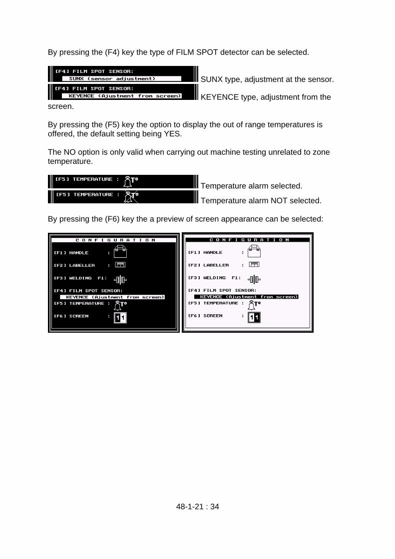
By pressing the (F4) key the type of FILM SPOT detector can be selected.
SUNX type, adjustment at the sensor.
KEYENCE type, adjustment from the screen. By pressing the (F5) key the option to display the out of range temperatures is offered, the default setting being YES. The NO option is only valid when carrying out machine testing unrelated to zone temperature.
Temperature alarm selected.
Temperature alarm NOT selected. By pressing the (F6) key the a preview of screen appearance can be selected:
48-1-21 : 35
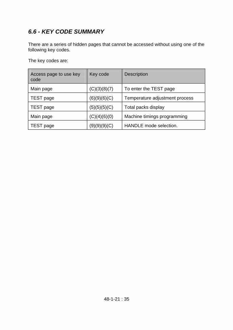
6.6 - KEY CODE SUMMARY There are a series of hidden pages that cannot be accessed without using one of the following key codes. The key codes are: Access page to use key code
Key code
Description
Main page
(C)(3)(8)(7)
To enter the TEST page
TEST page
(6)(9)(6)(C)
Temperature adjustment process
TEST page
(5)(5)(5)(C)
Total packs display
Main page
(C)(4)(6)(0)
Machine timings programming
TEST page
(9)(9)(9)(C)
HANDLE mode selection.

48-1-21 : 36
6.7 - ALARM LIST When an alarm is triggered the screen will flash and indicator will appear as shown on the following screen: When an alarm is triggered the machine finishes off the rest of the phases and before the transfer, operation is suspended. Once the problem is solved, by pressing (RUN) the machine can be re-started. 6.7.1 - ALARM DESCRIPTIONS. [1]CLAMP [F1] NOT CLOSED Alarm Number
1
Location
PHASE 1
Check: Outputs: 12x4 Inputs: 3x6 [2]BELTS [F1] NOT CLOSED Alarm Number
2
Location
PHASE 1
Check: Outputs: 22x4 Inputs: 5x6

48-1-21 : 37
[3]CUT [F1] NOT CLOSED Alarm Number
3
Location
PHASE 1
Check: Outputs: 3x4 Inputs: 4x6 [4]BELTS [F2] NOT CLOSED Alarm Number
4
Location
PHASE 2
Check: Outputs: 7x4 Inputs: 6x6 [5]SUCTION PADS [F2] DO NOT DESCEND Alarm Number
5
Location
PHASE 2
Check: Outputs: 5x4 Inputs: 9x6 [6]BELTS [F2] NOT OPEN Alarm Number
6
Location
PHASE 2
Check: Outputs: 7x4 Inputs: 6x6 [7]PROBE CUT OFF Alarm Number
7
Location
TEMPERATURE CONTROL
Indicates the zone has a fixed connection and temperature changes are not shown. Check whether the probes or the resistor have been cut off.

48-1-21 : 38
[8]TEMPERATURE INSUFFICIENT
Alarm Number
8
Location
TEMPERATURE CONTROL
Indicating that one or more zones are below the programmed temperature.
[9]GRIPPERS [F2] NOT CLOSED Alarm Number
9
Location
PHASE 2
Check: Outputs: 1x5 Inputs: 7x6 [10]SUCTION PADS [F2] DO NOT RISE Alarm Number
10
Location
PHASE 2
Check: Outputs: 5x4 Inputs: 11x6 [11]GRIPPERS [F2] NOT OPEN Alarm Number
11
Location
PHASE 2
Check: Outputs: 1x5 Inputs: 4x7 [12]SUCTION PADS [F2] NO INTERMEDIATE POSITION Alarm Number
12
Location
PHASE 2
Check: Outputs: 5x4 Inputs: 9x6, 11x6

48-1-21 : 39
[13]CLAMPS [F4] NOT OPEN Alarm Number
13
Location
PHASE 4
Check: Outputs: 11x4 Inputs: 23x6.
[14]CLAMPS [F4] NOT CLOSED Alarm Number
14
Location
PHASE 4
Check: Outputs: 11x4 Inputs: 23x6. [15]CLAMPS [F5] NOT OPEN Alarm Number
15
Location
PHASE 5
Check: Outputs: 29x4 Inputs: 20x6. [16]CLAMPS [F5] NOT CLOSED Alarm Number
16
Location
PHASE 5
Check: Outputs: 29x4 Inputs: 20x6. [17]FILM FEED [F5] PARALYZED Alarm Number
17
Location
PHASE 5 HANDLE
Check: Outputs: 25x4 Inputs: 30x6

48-1-21 : 40
[18] FILM SETBACK [F5] PARALYZED Alarm Number
18
Location
PHASE 5 HANDLE
Check: Outputs: 25x4 Inputs: 32x6 [19]CUTTING BAR [F5] NOT DOWN Alarm Number
19
Location
PHASE 5
Check: Outputs: 4x4 Inputs: 19x6 [20]WELDER [F1] NOT CLOSED Alarm Number
20
Location
PHASE 1
Check: Outputs: 13x4 Inputs: 21x6 [21]CLAMP [F1] NOT OPEN Alarm Number
21
Location
PHASE 1
Check: Outputs: 12x4 Inputs: 3x6 [22]CUTTER [F1] NOT OPEN Alarm Number
22
Location
PHASE 1
Check: Outputs: 3x4 Inputs: 4x6 [23] CUTTING BAR [F5] NOT UP

48-1-21 : 41
Alarm Number 23 Location
PHASE 5
Check: Outputs: 4x4 Inputs: 22x6 [24]FILM SPOT NOT SEEN Alarm Number
24
Location
PHASE 4
Check: Outputs: 3x5 Inputs: 26x6 [25]GATE [F3] NOT CLOSED Alarm Number
25
Location
PHASE 3
Check: Outputs: 6x4 Inputs: 28x6 [26]NOZZLE [F4] IS NOT IN FRONT Alarm Number
26
Location
PHASE 4
Check: Outputs: 14x4 Inputs: 31x6 [27]NOZZLE [F4] IS NOT BACK Alarm Number
27
Location
PHASE 4
Check: Outputs: 14x4 Inputs: 31x6 [28]GRIPPERS [F2] NOT OPEN Alarm Number
28

48-1-21 : 42
Location PHASE 2 Check: Outputs: 1x5 Inputs: 4x7 [29]HANDLE CUTTER [F5A] DOES NOT ADVANCE Alarm Number
29
Location
PHASE 5 HANDLE
Check: Outputs: 27x4 Inputs: 5x7
[30]HANDLE PRESSER [F5A] DOES NOT RISE Alarm Number
30
Location
PHASE 5 HANDLE
Check: Outputs: 28x4 Inputs: 9x7 [31]HANDLE CUTTER [F5A] DOES NOT RETURN Alarm Number
31
Location
PHASE 5 HANDLE
Check: Outputs: 27x4 Inputs: 7x7 [32]HANDLE PRESSER [F5A] DOES NOT DESCEND Alarm Number
32
Location
PHASE 5 HANDLE
Check: Outputs: 28x4 Inputs: 8x7 [33]PLATFORM [F3] DOES NOT RISE Alarm Number
33
PHASE 3
48-1-21 : 43
Location Check: Outputs: 20x4 Inputs: 10x7 [34]PLATFORM [F3] DOES NOT GO DOWN Alarm Number
34
Location
PHASE 3
Check: Outputs: 20x4 Inputs: 10x7 [35]LACK OF FILM [F1] Alarm Number
35
Location
PHASE 1
Check to see if there is a lack of film in PHASE 1, if indeed there is film then check: Inputs: 15x7,29x7 [36]LACK OF MESH [F1] Alarm Number
36
Location
PHASE 1
Check to see if there is a lack of mesh in PHASE 1, if indeed there is mesh then check: Inputs: 11x7 [37]LACK OF HANDLE FILM [F5A] Alarm Number
37
Location
PHASE 5 HANDLE
Check to see is if there is film for the HANDLE, if indeed there is film then check: Inputs: 12x7 [38]TRANSFER ERROR [TR] Alarm Number
38
Location
TRANSFER
Check:

48-1-21 : 44
Outputs: 4x5 Inputs: 27x6, 12x6 [39]CAM NOT DETECTED IN TRANSFER [TR] Alarm Number
39
Location
TRANSFER
Check: Outputs: 4x5 Inputs: 12x6 [40]BAG UNHOOKED IN PHASE 2 Alarm Number
40
Location
PHASE 2
Check: Inputs: 30x7 [41]ERROR IN LABELLER Alarm Number
41
Location
PHASE 2
Check: Outputs: 9x5 Inputs: 31x7 [42]ERROR IN MESH INFEED [F4] Alarm Number
42
Location
PHASE 4
Check: Outputs: 2x5 Inputs: 29x6 [43]INCORRECT BAG[F1] Alarm Number
43
Location
PHASE 1
Check: Outputs: Inputs: 12x6
48-1-21 : 46
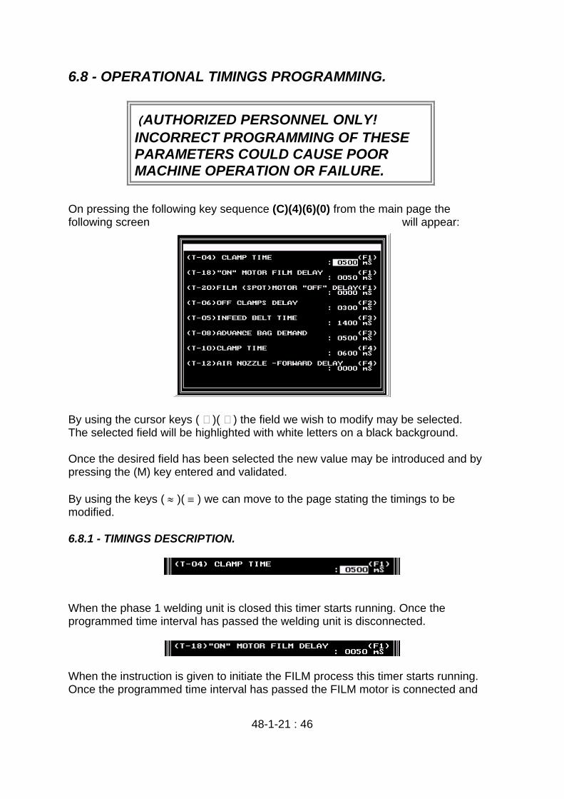
6.8 - OPERATIONAL TIMINGS PROGRAMMING.
(AUTHORIZED PERSONNEL ONLY! INCORRECT PROGRAMMING OF THESE PARAMETERS COULD CAUSE POOR MACHINE OPERATION OR FAILURE.
On pressing the following key sequence (C)(4)(6)(0) from the main page the following screen will appear: By using the cursor keys ( )( ) the field we wish to modify may be selected. The selected field will be highlighted with white letters on a black background. Once the desired field has been selected the new value may be introduced and by pressing the (M) key entered and validated. By using the keys ( ≈ )( ≡ ) we can move to the page stating the timings to be modified. 6.8.1 - TIMINGS DESCRIPTION.
When the phase 1 welding unit is closed this timer starts running. Once the programmed time interval has passed the welding unit is disconnected.
When the instruction is given to initiate the FILM process this timer starts running. Once the programmed time interval has passed the FILM motor is connected and

48-1-21 : 47
the process commences.
When working in FILM dosing by SPOT detection mode, this timer starts running when the detector sees the SPOT. Once the programmed time interval has passed the FILM dosing motor is disconnected.
This timer starts running when the suction pads in phase 2 are in the up position. Once the programmed time interval has passed the grippers are disconnected.
When a pack is requested from the input conveyor belt, and there is a pack on the belt, the conveyor belt starts and this timer starts to run. Once the programmed time interval has passed the conveyor belt motor is disconnected.
When the input belt is started, a timer with the (T-05)-(T-08) value is started. Once the programmed time interval has passed a pack is requested from the weigh cell. (Therefore, when there is only the time programmed in T-8 to go for belt disconnection, a pack is required from the weigh cell).
When the phase 4 clamp is closed this timer starts to run. Once the programmed time interval has passed the clamp is disconnected (phase 4 welding time)
When phase 4 commences, this timer is started. Once the programmed time interval has passed, an instruction is given to bring in the air nozzles
When the nozzles are in the forward position in phase 4, this timer is started. Once the programmed time interval has passed, an instruction is given to connect the

48-1-21 : 48
clamp.
When the sword (cutting bar) disconnection instruction is given in phase 5, this timer starts to run. When the programmed time interval has passed an instruction is given to connect the clamp. (To avoid the possibility that clamp A hooks up on the sword (cutting bar)
When the instruction is given to connect the phase 5 clamp, this timer is started. When the programmed time interval has passed the clamp is disconnected.
When bag transfer commences, this timer is started. When the programmed time interval has passed, an instruction is given to initiate the FILM dispensing process in phase 1.
When bag transfer commences, this timer is started. When the programmed time interval has passed, an instruction is given to connect the sword (cutting bar) (If there is a HANDLE prepared, otherwise the machine will wait).
When bag transfer commences, this timer is started. When the programmed time interval has passed, an instruction is given to connect the elevating platform.
When the transfer motor disconnects, this timer is started. When the programmed time interval has passed, the transfer finish is indicated and therefore all the phases are enabled to start operation.

48-1-21 : 49
This is so as to avoid movement of the different phase mechanisms, before the transfer has stopped completely (due to the effects of inertia).
When the product input belt connects, this timer starts. When the programmed time interval has passed the elevator is deenergized and the output belt vibrator is started (if this option has been selected).
When the transfer initiates, this timer is started. When the programmed time interval has passed, the phase 1 belts open and the phase 1 film extraction delay is initiated.
When the suction pads reach the down position, this timer is started. When the programmed time interval has passed, the venturi is switched on.
When the instruction is given to stop the film dosing motor, this timer is started. When the programmed time interval has passed, an instruction is given to close the phase 1 belts.
When the transfer is switched on this timer is started. When the programmed time interval has passed, bag blowing in transfer starts.
When the programmed time interval (T-29) has passed and bag blowing is switched on this timer is started. When the programmed time interval has passed bag blowing is disconnected.
When the transfer is switched on this timer is started. When the programmed time interval has passed, the net (mesh) placer mechanism in transfer is switched on. If a 0 value is programmed, the placer mechanism does not operate.
48-1-21 : 50
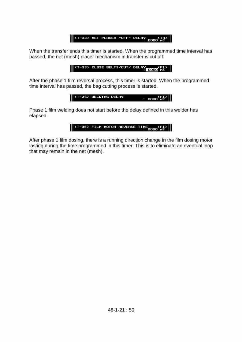
When the transfer ends this timer is started. When the programmed time interval has passed, the net (mesh) placer mechanism in transfer is cut off.
After the phase 1 film reversal process, this timer is started. When the programmed time interval has passed, the bag cutting process is started.
Phase 1 film welding does not start before the delay defined in this welder has elapsed.
After phase 1 film dosing, there is a running direction change in the film dosing motor lasting during the time programmed in this timer. This is to eliminate an eventual loop that may remain in the net (mesh).


![Users Manual - NTT Communications · [050 plus Users Manual for Windows PC] P.04 ・・・Section01 : Basic Operation . Chapter. 01 Basic Operation . P.06・・・ Section01 : make](https://img.pdfslide.net/doc/110x75/5ac1ad217f8b9ae45b8da382/users-manual-ntt-050-plus-users-manual-for-windows-pc-p04-section01.jpg)