Embed Size (px)
Citation preview
OPERATOR AND PARTS MANUAL
Disc MowerModel 245, 280, 320
082016 M0001
6990633 (1-13) Printed in U.S.A. © Bobcat Company 2013 062013 | Rev 1 | 88664296

Table of Contents - Disc Mower
TABLE OF CONTENTS
INTRODUCTION . . . . . . . . . . . . . . . . . . . . . . . . . . . . . . . . . . . . . . . . . . . . . . . . . . . . . . . . . . . . . . . .7
SAFETY . . . . . . . . . . . . . . . . . . . . . . . . . . . . . . . . . . . . . . . . . . . . . . . . . . . . . . . . . . . . . . . . . . . . . . 11
ASSEMBLY . . . . . . . . . . . . . . . . . . . . . . . . . . . . . . . . . . . . . . . . . . . . . . . . . . . . . . . . . . . . . . . . . . . 21
OPERATION . . . . . . . . . . . . . . . . . . . . . . . . . . . . . . . . . . . . . . . . . . . . . . . . . . . . . . . . . . . . . . . . . . . 25
MAINTENANCE . . . . . . . . . . . . . . . . . . . . . . . . . . . . . . . . . . . . . . . . . . . . . . . . . . . . . . . . . . . . . . . . 47
PARTS IDENTIFICATION . . . . . . . . . . . . . . . . . . . . . . . . . . . . . . . . . . . . . . . . . . . . . . . . . . . . . . . . . 61
SPECIFICATIONS . . . . . . . . . . . . . . . . . . . . . . . . . . . . . . . . . . . . . . . . . . . . . . . . . . . . . . . . . . . . . 121
WARRANTY . . . . . . . . . . . . . . . . . . . . . . . . . . . . . . . . . . . . . . . . . . . . . . . . . . . . . . . . . . . . . . . . . . 127
ALPHABETICAL INDEX . . . . . . . . . . . . . . . . . . . . . . . . . . . . . . . . . . . . . . . . . . . . . . . . . . . . . . . . . 131
Manufacturer’s Statement: For technical reasons, Buhler Industries Inc. reserves the right to modify machinery designand specifications provided herein without any preliminary notice. Information provided herein is of descriptive nature.Performance quality may depend on bale structure, applied techniques, weather conditions and other factors.
3

Table of Contents - Disc Mower
4
Warranty Registration - Disc Mower
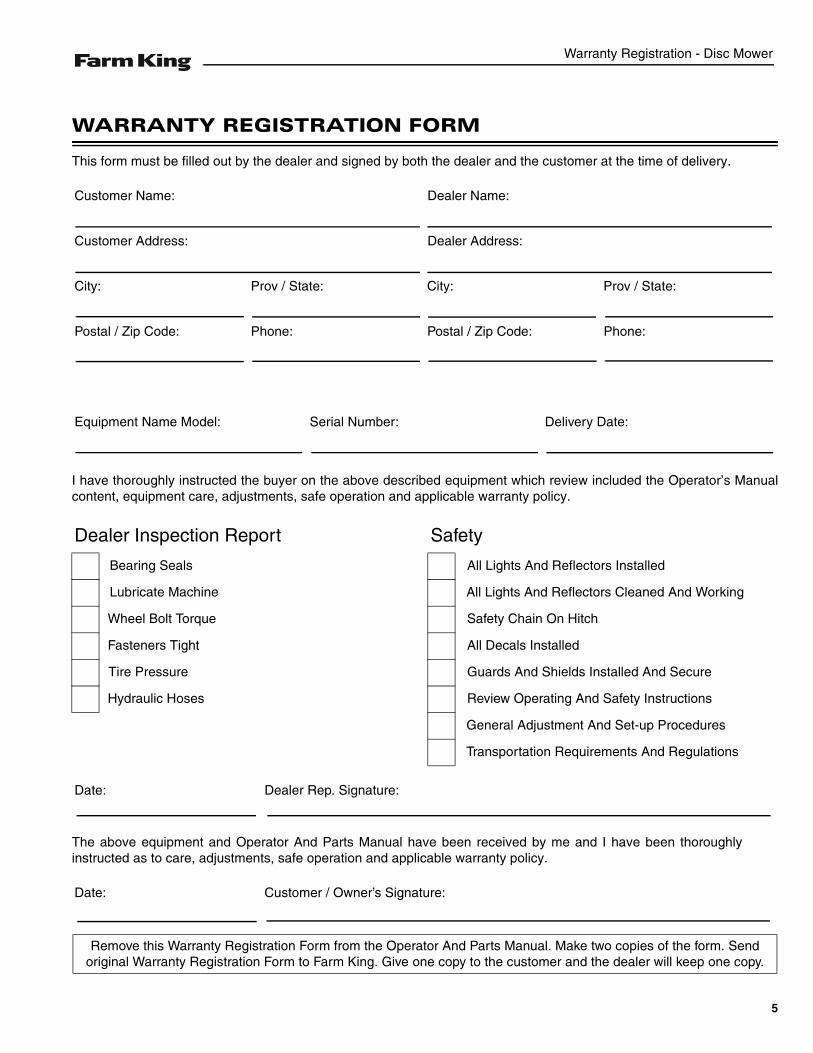
WARRANTY REGISTRATION FORM
This form must be filled out by the dealer and signed by both the dealer and the customer at the time of delivery.
I have thoroughly instructed the buyer on the above described equipment which review included the Operator’s Manualcontent, equipment care, adjustments, safe operation and applicable warranty policy.
The above equipment and Operator And Parts Manual have been received by me and I have been thoroughlyinstructed as to care, adjustments, safe operation and applicable warranty policy.
Customer Name: Dealer Name:
Customer Address: Dealer Address:
City: Prov / State: City: Prov / State:
Postal / Zip Code: Phone: Postal / Zip Code: Phone:
Equipment Name Model: Serial Number: Delivery Date:
Dealer Inspection Report Safety
Bearing Seals All Lights And Reflectors Installed
Lubricate Machine All Lights And Reflectors Cleaned And Working
Wheel Bolt Torque Safety Chain On Hitch
Fasteners Tight All Decals Installed
Tire Pressure Guards And Shields Installed And Secure
Hydraulic Hoses Review Operating And Safety Instructions
General Adjustment And Set-up Procedures
Transportation Requirements And Regulations
Date: Dealer Rep. Signature:
Date: Customer / Owner’s Signature:
Remove this Warranty Registration Form from the Operator And Parts Manual. Make two copies of the form. Send original Warranty Registration Form to Farm King. Give one copy to the customer and the dealer will keep one copy.
5

Warranty Registration - Disc Mower
6
Introduction - Disc Mower
INTRODUCTION
This Operator And Parts Manual was written to give the owner / operator instructions on the safe operation, maintenanceand part identification of the Farm King equipment. READ AND UNDERSTAND THIS OPERATOR AND PARTS MANUALBEFORE OPERATING YOUR FARM KING EQUIPMENT. If you have any questions, see your Farm King dealer. Thismanual may illustrate options and accessories not installed on your Farm King equipment.
OWNER’S INFORMATION . . . . . . . . . . . . . . . . . . . . . . . . . . . . . . . . . . . . . . . . . . . . . . . . . . . . . . . . . 9Serial Number Location . . . . . . . . . . . . . . . . . . . . . . . . . . . . . . . . . . . . . . . . . . . . . . . . . . . . . . . . 9
EQUIPMENT IDENTIFICATION . . . . . . . . . . . . . . . . . . . . . . . . . . . . . . . . . . . . . . . . . . . . . . . . . . . . 10Component Location . . . . . . . . . . . . . . . . . . . . . . . . . . . . . . . . . . . . . . . . . . . . . . . . . . . . . . . . . . 10
7

Introduction - Disc Mower
8
Introduction - Disc Mower
OWNER’S INFORMATION
Thank you for your decision to purchase a Farm KingDisc Mower. To ensure maximum performance of yourequipment, it is mandatory that you thoroughly study theOperator And Parts Manual and follow therecommendations. Proper operation and maintenanceare essential to maximize equipment life and preventpersonal injury.
Operate and maintain this equipment in a safe mannerand in accordance with all applicable local, state, andfederal codes, regulations and / or laws. Follow all on-product labeling and instructions.
Make sure that all personnel have read this Operator andParts Manual and thoroughly understand safe andcorrect operating, installation and maintenanceprocedures.
Farm King is continually working to improve its products.Farm King reserves the right to make any improvementsor changes as deemed practical and possible withoutincurring any responsibility or obligation to make anychanges or additions to equipment sold previously.
Although great care has been taken to ensure theaccuracy of this publication, Farm King makes nowarranty or guarantee of any kind, written or expressed,implied or otherwise with regard to the informationcontained within this manual. Farm King assumes noresponsibility for any errors that may appear in thismanual and shall not be liable under any circumstancesfor incidental, consequential or punitive damages inconnection with, or arising from the use of this manual.
Keep this manual available for frequent reference. All newoperators or owners must review the manual before usingthe equipment and annually thereafter. Contact yourFarm King Dealer if you need assistance, information, oradditional copies of the manual. Visit our website atwww.farm-king.com for a complete list of dealers inyour area.
The directions left, right, front and rear, as mentionedthroughout this manual, are as viewed from the rear ofthe equipment.
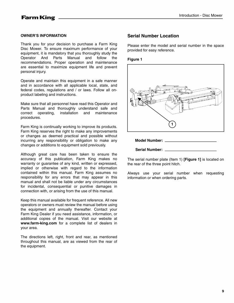
Serial Number Location
Please enter the model and serial number in the spaceprovided for easy reference.
Figure 1
The serial number plate (Item 1) [Figure 1] is located onthe rear of the three point hitch.
Always use your serial number when requestinginformation or when ordering parts.
1
Model Number:
Serial Number:
9
Introduction - Disc Mower
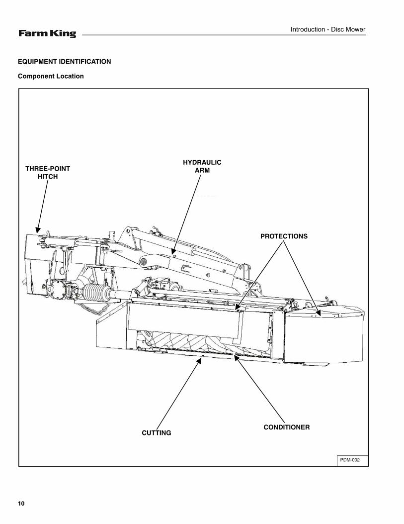
EQUIPMENT IDENTIFICATION
Component Location
PDM-002
THREE-POINT HITCH
HYDRAULIC ARM
PROTECTIONS
CONDITIONERCUTTING
10
Safety - Disc Mower
SAFETY
SAFETY INSTRUCTIONS . . . . . . . . . . . . . . . . . . . . . . . . . . . . . . . . . . . . . . . . . . . . . . . . . . . . . . . . 13Safe Operation Is The Operator’s Responsibility . . . . . . . . . . . . . . . . . . . . . . . . . . . . . . . . . . . . 13Safe Operation Needs A Qualified Operator . . . . . . . . . . . . . . . . . . . . . . . . . . . . . . . . . . . . . . . . 13Use Safety Rules . . . . . . . . . . . . . . . . . . . . . . . . . . . . . . . . . . . . . . . . . . . . . . . . . . . . . . . . . . . . 14Transport Safety . . . . . . . . . . . . . . . . . . . . . . . . . . . . . . . . . . . . . . . . . . . . . . . . . . . . . . . . . . . . . 14Machine Requirements And Capabilities . . . . . . . . . . . . . . . . . . . . . . . . . . . . . . . . . . . . . . . . . .15
FIRE PREVENTION . . . . . . . . . . . . . . . . . . . . . . . . . . . . . . . . . . . . . . . . . . . . . . . . . . . . . . . . . . . . . 15Maintenance . . . . . . . . . . . . . . . . . . . . . . . . . . . . . . . . . . . . . . . . . . . . . . . . . . . . . . . . . . . . . . . . 15Operation . . . . . . . . . . . . . . . . . . . . . . . . . . . . . . . . . . . . . . . . . . . . . . . . . . . . . . . . . . . . . . . . . . 15Starting . . . . . . . . . . . . . . . . . . . . . . . . . . . . . . . . . . . . . . . . . . . . . . . . . . . . . . . . . . . . . . . . . . . . 15Electrical . . . . . . . . . . . . . . . . . . . . . . . . . . . . . . . . . . . . . . . . . . . . . . . . . . . . . . . . . . . . . . . . . . . 16Hydraulic System . . . . . . . . . . . . . . . . . . . . . . . . . . . . . . . . . . . . . . . . . . . . . . . . . . . . . . . . . . . . 16Welding And Grinding . . . . . . . . . . . . . . . . . . . . . . . . . . . . . . . . . . . . . . . . . . . . . . . . . . . . . . . . . 16Fire Extinguishers . . . . . . . . . . . . . . . . . . . . . . . . . . . . . . . . . . . . . . . . . . . . . . . . . . . . . . . . . . . .16
SAFETY SIGNS (DECALS) . . . . . . . . . . . . . . . . . . . . . . . . . . . . . . . . . . . . . . . . . . . . . . . . . . . . . . . 17
EQUIPMENT DECALS AND SIGNS . . . . . . . . . . . . . . . . . . . . . . . . . . . . . . . . . . . . . . . . . . . . . . . . 18
SAFETY SIGN-OFF FORM . . . . . . . . . . . . . . . . . . . . . . . . . . . . . . . . . . . . . . . . . . . . . . . . . . . . . . . 20
11

Safety - Disc Mower
12
Safety - Disc Mower
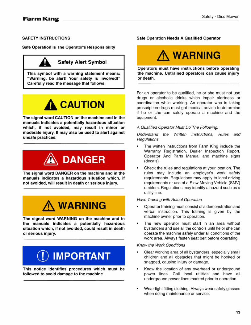
SAFETY INSTRUCTIONS
Safe Operation Is The Operator’s Responsibility
Safe Operation Needs A Qualified Operator
For an operator to be qualified, he or she must not usedrugs or alcoholic drinks which impair alertness orcoordination while working. An operator who is takingprescription drugs must get medical advice to determineif he or she can safely operate a machine and theequipment.
A Qualified Operator Must Do The Following:
Understand the Written Instructions, Rules andRegulations
• The written instructions from Farm King include theWarranty Registration, Dealer Inspection Report,Operator And Parts Manual and machine signs(decals).
• Check the rules and regulations at your location. Therules may include an employer’s work safetyrequirements. Regulations may apply to local drivingrequirements or use of a Slow Moving Vehicle (SMV)emblem. Regulations may identify a hazard such as autility line.
Have Training with Actual Operation
• Operator training must consist of a demonstration andverbal instruction. This training is given by themachine owner prior to operation.
• The new operator must start in an area withoutbystanders and use all the controls until he or she canoperate the machine safely under all conditions of thework area. Always fasten seat belt before operating.
Know the Work Conditions
• Clear working area of all bystanders, especially smallchildren and all obstacles that might be hooked orsnagged, causing injury or damage.
• Know the location of any overhead or undergroundpower lines. Call local utilities and have allunderground power lines marked prior to operation.
• Wear tight fitting clothing. Always wear safety glasseswhen doing maintenance or service.
This symbol with a warning statement means:“Warning, be alert! Your safety is involved!”Carefully read the message that follows.
Safety Alert Symbol
The signal word CAUTION on the machine and in themanuals indicates a potentially hazardous situationwhich, if not avoided, may result in minor ormoderate injury. It may also be used to alert againstunsafe practices.
The signal word DANGER on the machine and in themanuals indicates a hazardous situation which, ifnot avoided, will result in death or serious injury.
The signal word WARNING on the machine and inthe manuals indicates a potentially hazardoussituation which, if not avoided, could result in deathor serious injury.
This notice identifies procedures which must befollowed to avoid damage to the machine.
Operators must have instructions before operatingthe machine. Untrained operators can cause injuryor death.
13
Safety - Disc Mower
SAFETY INSTRUCTIONS (CONT’D)
Use Safety Rules
• Read and follow instructions in this manual and thetractor’s Operators Manual before operating.
• Under no circumstances should young children beallowed to work with this equipment.
• This equipment is dangerous to children and personsunfamiliar with its operation.
• If the elderly are assisting with work, their physicallimitations need to be recognized andaccommodated.
• Stay clear of overhead power lines. Electrocution canoccur without direct contact.
• Check for overhead and / or underground lines beforeoperating equipment (if applicable).
• In addition to the design and configuration ofequipment, hazard control and accident preventionare dependent upon the awareness, concern,prudence and proper training of personnel involved inthe operation, transport, maintenance and storage ofequipment.
• Check that the equipment is securely fastened to thetractor / towing vehicle.
• Make sure all the machine controls are in theNEUTRAL position before starting the machine.
• Operate the equipment only from the operator’sposition.
• Operate the equipment according to the OperatorAnd Parts Manual.
• When learning to operate the equipment, do it at aslow rate in an area clear of bystanders, especiallysmall children.
• DO NOT permit personnel to be in the work areawhen operating the equipment.
• The equipment must be used ONLY on approvedtractors / transport vehicles.
• DO NOT modify the equipment in any way.Unauthorized modification may impair the functionand / or safety and could affect the life of theequipment.
• DO NOT make any adjustments or repairs on theequipment while the machine is running.
• Keep shields and guards in place. Replace ifdamaged.
Transport Safety
• DO NOT exceed 20 mph (32 kph). Reduce speed onrough roads and surfaces.
• Comply with state and local laws governing highwaysafety and movement of machinery on public roads.
• The use of flashing amber lights is acceptable in mostlocalities. However, some localities prohibit their use.Local laws should be checked for all highway lightingand marking requirements.
• Always install transport locks, pins or brackets beforetransporting.
• Always yield to oncoming traffic in all situations andmove to the side of the road so any following trafficmay pass.
• Always enter curves or drive up or down hills at a lowspeed and at a gradual steering angle.
• Never allow riders on either tractor or equipment.
• Keep tractor / towing vehicle in a lower gear at alltimes when traveling down steep grades.
• Maintain proper brake settings at all times (ifequipped).
• Stay away from overhead power lines. Electrocutioncan occur without direct contact.
14
Safety - Disc Mower
Machine Requirements And Capabilities
• Stop the machine and engage the parking brake.Install blocks in front of and behind the rear tires of themachine. Install blocks underneath and support theequipment securely before working under raisedequipment.
• Keep bystanders clear of moving parts and the workarea. Keep children away.
• Use increased caution on slopes and near banks andditches to prevent overturn.
• Make certain that the Slow Moving Vehicle (SMV)emblem is installed so that it is visible and legible.When transporting the equipment, use the flashingwarning lights (if equipped) and follow all localregulations.
• Operate this equipment with a machine equipped withan approved Roll-Over Protective Structure (ROPS).Always wear seat belt when the ROPS is up. Seriousinjury or death could result from falling off themachine.
• Before leaving the operator’s position:
1. Always park on a flat level surface.2. Place all controls in neutral.3. Engage the parking brake.4. Stop engine.5. Wait for all moving parts to stop.
• Carry passengers only in designated seating areas.Never allow riders on the machine or equipment.Falling off can result in serious injury or death.
• Start the equipment only when properly seated in theoperator’s seat. Starting a machine in gear can resultin serious injury or death.
• Operate the machine and equipment from theoperator's position only.
• The parking brake must be engaged before leavingthe operator’s seat. Rollaway can occur because thetransmission may not prevent machine movement.
FIRE PREVENTION
Maintenance
The machine and some equipment have componentsthat are at high temperatures under normal operatingconditions. The primary source of high temperatures isthe engine and exhaust system. The electrical system, ifdamaged or incorrectly maintained, can be a source ofarcs or sparks.
Flammable debris (leaves, straw, etc.) must be removedregularly. If flammable debris is allowed to accumulate, itcan cause a fire hazard. Clean often to avoid thisaccumulation.
All fuels, most lubricants and some coolant mixtures areflammable. Flammable fluids that are leaking or spilledonto hot surfaces or onto electrical components cancause a fire.
Operation
The Farm King machine must be in good operatingcondition before use.
Check all of the items listed on the service scheduleunder the 8 hour column. (See “SERVICE SCHEDULE”on page 50.)
Do not use the machine where exhaust, arcs, sparks orhot components can contact flammable material,explosive dust or gases.
Starting
Use the procedure in the tractor’s operator’s manual forconnecting the battery and for jump starting.
15
Safety - Disc Mower
Electrical
Check all electrical wiring and connections for damage.Keep the battery terminals clean and tight. Repair orreplace any damaged part or wires that are loose orfrayed.
Hydraulic System
Check hydraulic tubes, hoses and fittings for damageand leakage. Never use open flame or bare skin to checkfor leaks. Hydraulic tubes and hoses must be properlyrouted and have adequate support and secure clamps.Tighten or replace any parts that show leakage.
Always clean fluid spills. Do not use gasoline or dieselfuel for cleaning parts. Use commercial nonflammablesolvents.
Welding And Grinding
Always clean the machine and equipment, disconnectthe battery, and disconnect the wiring from the machinecontrols before welding. Cover rubber hoses, battery andall other flammable parts. Keep a fire extinguisher nearthe machine when welding.
Have good ventilation when grinding or welding paintedparts. Wear dust mask when grinding painted parts.Toxic dust or gas can be produced.
Dust generated from repairing nonmetallic parts such ashoods, fenders or covers can be flammable or explosive.Repair such components in a well ventilated area awayfrom open flames or sparks.
Fire Extinguishers
Know where fire extinguishers and first aid kits arelocated and how to use them. Inspect the fireextinguisher and service the fire extinguisher regularly.Obey the recommendations on the instructions plate.
16
Safety - Disc Mower
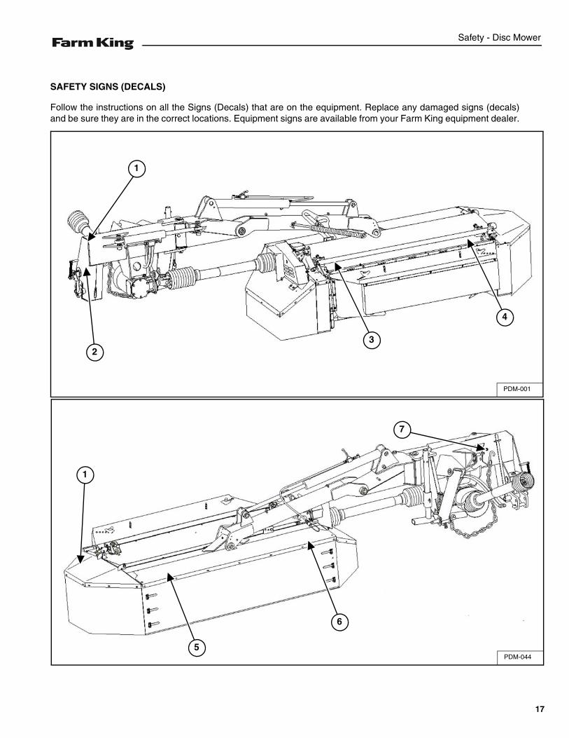
SAFETY SIGNS (DECALS)
Follow the instructions on all the Signs (Decals) that are on the equipment. Replace any damaged signs (decals)and be sure they are in the correct locations. Equipment signs are available from your Farm King equipment dealer.
PDM-044
1
5
6
7
PDM-001
1
23
4
17
Safety - Disc Mower
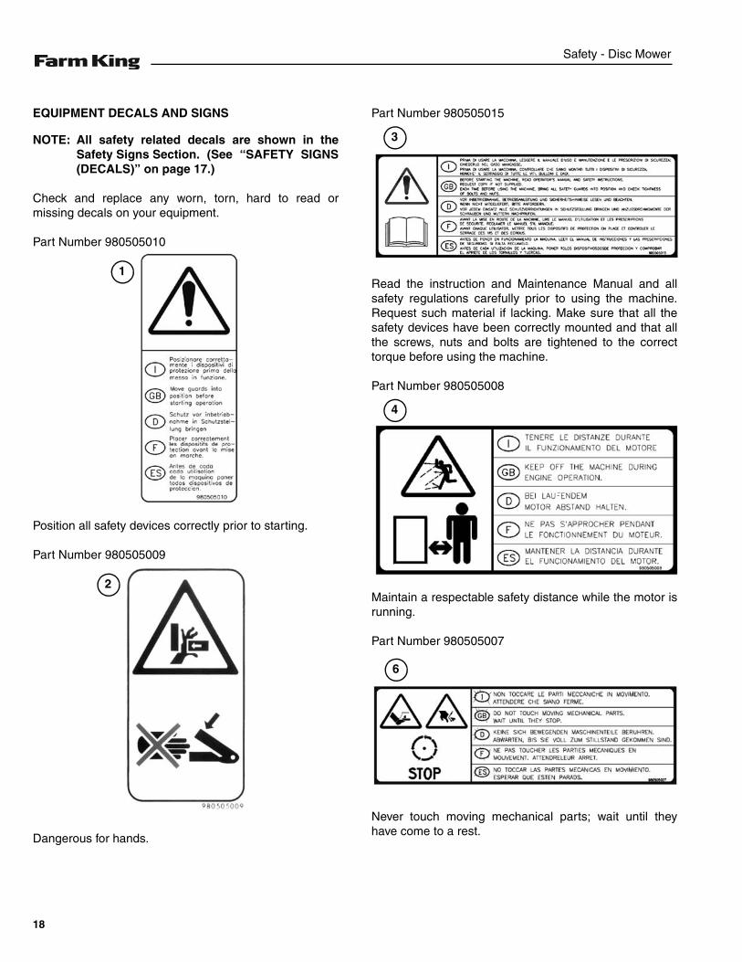
EQUIPMENT DECALS AND SIGNS
NOTE: All safety related decals are shown in theSafety Signs Section. (See “SAFETY SIGNS(DECALS)” on page 17.)
Check and replace any worn, torn, hard to read ormissing decals on your equipment.
Part Number 980505010
Position all safety devices correctly prior to starting.
Part Number 980505009
Dangerous for hands.
Part Number 980505015
Read the instruction and Maintenance Manual and allsafety regulations carefully prior to using the machine.Request such material if lacking. Make sure that all thesafety devices have been correctly mounted and that allthe screws, nuts and bolts are tightened to the correcttorque before using the machine.
Part Number 980505008
Maintain a respectable safety distance while the motor isrunning.
Part Number 980505007
Never touch moving mechanical parts; wait until theyhave come to a rest.
1
2
3
4
6
18
Safety - Disc Mower
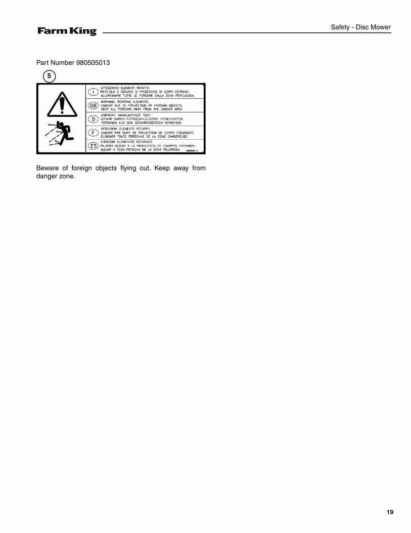
Part Number 980505013
Beware of foreign objects flying out. Keep away fromdanger zone.
5
19
Safety - Disc Mower
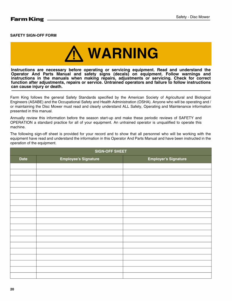
SAFETY SIGN-OFF FORM
Farm King follows the general Safety Standards specified by the American Society of Agricultural and BiologicalEngineers (ASABE) and the Occupational Safety and Health Administration (OSHA). Anyone who will be operating and /or maintaining the Disc Mower must read and clearly understand ALL Safety, Operating and Maintenance informationpresented in this manual.
Annually review this information before the season start-up and make these periodic reviews of SAFETY andOPERATION a standard practice for all of your equipment. An untrained operator is unqualified to operate thismachine.
The following sign-off sheet is provided for your record and to show that all personnel who will be working with theequipment have read and understand the information in this Operator And Parts Manual and have been instructed in theoperation of the equipment.
SIGN-OFF SHEET
Date Employee’s Signature Employer’s Signature
Instructions are necessary before operating or servicing equipment. Read and understand theOperator And Parts Manual and safety signs (decals) on equipment. Follow warnings andinstructions in the manuals when making repairs, adjustments or servicing. Check for correctfunction after adjustments, repairs or service. Untrained operators and failure to follow instructionscan cause injury or death.
20

Assembly - Disc Mower
ASSEMBLY
GENERAL ASSEMBLY INFORMATION . . . . . . . . . . . . . . . . . . . . . . . . . . . . . . . . . . . . . . . . . . . . . 23Component Unloading And Identification . . . . . . . . . . . . . . . . . . . . . . . . . . . . . . . . . . . . . . . . . .23
21

Assembly - Disc Mower
22
Assembly - Disc Mower
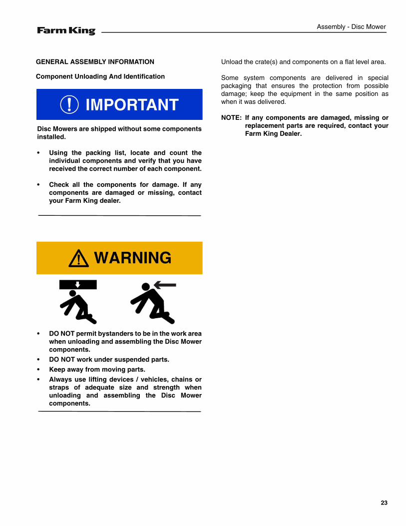
GENERAL ASSEMBLY INFORMATION
Component Unloading And Identification
Unload the crate(s) and components on a flat level area.
Some system components are delivered in specialpackaging that ensures the protection from possibledamage; keep the equipment in the same position aswhen it was delivered.
NOTE: If any components are damaged, missing orreplacement parts are required, contact yourFarm King Dealer.
Disc Mowers are shipped without some componentsinstalled.
• Using the packing list, locate and count theindividual components and verify that you havereceived the correct number of each component.
• Check all the components for damage. If anycomponents are damaged or missing, contactyour Farm King dealer.
• DO NOT permit bystanders to be in the work areawhen unloading and assembling the Disc Mowercomponents.
• DO NOT work under suspended parts.
• Keep away from moving parts.
• Always use lifting devices / vehicles, chains orstraps of adequate size and strength whenunloading and assembling the Disc Mowercomponents.
23

Assembly - Disc Mower
24
Operation - Disc Mower
OPERATION
GENERAL INFORMATION . . . . . . . . . . . . . . . . . . . . . . . . . . . . . . . . . . . . . . . . . . . . . . . . . . .27Pre - Operation Checklist . . . . . . . . . . . . . . . . . . . . . . . . . . . . . . . . . . . . . . . . . . . . . . . . . .27Break - In Checklist . . . . . . . . . . . . . . . . . . . . . . . . . . . . . . . . . . . . . . . . . . . . . . . . . . . . . . .28Tractor Requirements . . . . . . . . . . . . . . . . . . . . . . . . . . . . . . . . . . . . . . . . . . . . . . . . . . . . .29Entering And Leaving The Operator’s Position . . . . . . . . . . . . . . . . . . . . . . . . . . . . . . . . . .30
INITIAL SET-UP . . . . . . . . . . . . . . . . . . . . . . . . . . . . . . . . . . . . . . . . . . . . . . . . . . . . . . . . . . . .30Connecting Three-Point Disc Mower To The Tractor . . . . . . . . . . . . . . . . . . . . . . . . . . . . . .30Adjusting Rotating Group Tilt . . . . . . . . . . . . . . . . . . . . . . . . . . . . . . . . . . . . . . . . . . . . . . .31Connecting The PTO Driveline (Three-Point Models) . . . . . . . . . . . . . . . . . . . . . . . . . . . . .32PTO Driveline . . . . . . . . . . . . . . . . . . . . . . . . . . . . . . . . . . . . . . . . . . . . . . . . . . . . . . . . . . .33Connecting Hydraulic Lines . . . . . . . . . . . . . . . . . . . . . . . . . . . . . . . . . . . . . . . . . . . . . . . .36Operating Disc Mower (All Models) . . . . . . . . . . . . . . . . . . . . . . . . . . . . . . . . . . . . . . . . . .37
TRANSPORTING . . . . . . . . . . . . . . . . . . . . . . . . . . . . . . . . . . . . . . . . . . . . . . . . . . . . . . . . . . .43Requirements . . . . . . . . . . . . . . . . . . . . . . . . . . . . . . . . . . . . . . . . . . . . . . . . . . . . . . . . . . .43Transport Position . . . . . . . . . . . . . . . . . . . . . . . . . . . . . . . . . . . . . . . . . . . . . . . . . . . . . . . .44Removing The Disc Mower . . . . . . . . . . . . . . . . . . . . . . . . . . . . . . . . . . . . . . . . . . . . . . . . .45
25

Operation - Disc Mower
26
Operation - Disc Mower
GENERAL INFORMATION
Pre - Operation Checklist
Before operating the Disc Mower for the first time andeach time thereafter, check the following items:
1. Lubricate the equipment per the schedule outline inthe Maintenance Section. (See “SERVICESCHEDULE” on page 50.)
2. Check the Disc Mower hitch for damaged, loose ormissing parts. Repair as needed before operation.
3. Fully clean the equipment.
4. Inspect all safety reflective decals, slow movingvehicle decals and lights where applicable.
5. Check condition of all hydraulic components for leaks.Repair as required.
NOTE: Do not operate with hydraulic leaks.
6. Verify that the safety lock is in the unlock position.
7. Verify that the Disc Mower is properly connected tothe tractor with the safety chain.
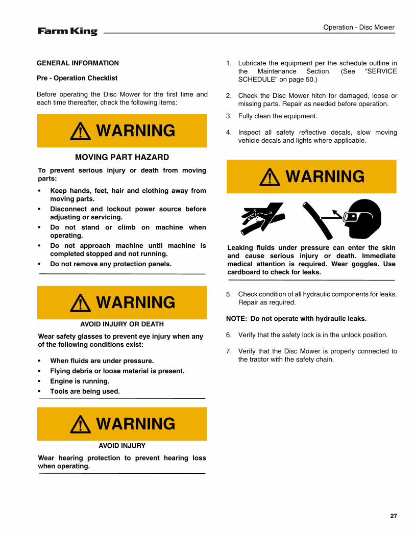
MOVING PART HAZARD
To prevent serious injury or death from movingparts:
• Keep hands, feet, hair and clothing away frommoving parts.
• Disconnect and lockout power source beforeadjusting or servicing.
• Do not stand or climb on machine whenoperating.
• Do not approach machine until machine iscompleted stopped and not running.
• Do not remove any protection panels.
AVOID INJURY OR DEATH
Wear safety glasses to prevent eye injury when anyof the following conditions exist:
• When fluids are under pressure.
• Flying debris or loose material is present.
• Engine is running.
• Tools are being used.
AVOID INJURY
Wear hearing protection to prevent hearing losswhen operating.
Leaking fluids under pressure can enter the skinand cause serious injury or death. Immediatemedical attention is required. Wear goggles. Usecardboard to check for leaks.
27
Operation - Disc Mower
Break - In Checklist
Check the following mechanical items after 8 hours ofoperation:
1. Make sure that all hardware are tightened (especiallythose of the cutters).
Check the following mechanical items after 50 hours ofoperation:
1. Change oil in the cutting bar.
2. Change oil in the gear box.
28
Operation - Disc Mower
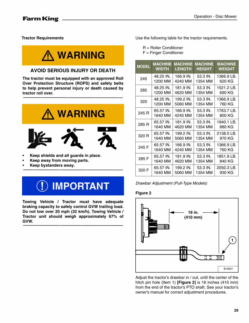
Tractor Requirements Use the following table for the tractor requirements.
R = Roller ConditionerF = Finger Conditioner
Drawbar Adjustment (Pull-Type Models)
Figure 2
Adjust the tractor’s drawbar in / out, until the center of thehitch pin hole (Item 1) [Figure 2] is 16 inches (410 mm)from the end of the tractor’s PTO shaft. See your tractor’sowner’s manual for correct adjustment procedures.
AVOID SERIOUS INJURY OR DEATH
The tractor must be equipped with an approved RollOver Protection Structure (ROPS) and safety beltsto help prevent personal injury or death caused bytractor roll over.
• Keep shields and all guards in place.• Keep away from moving parts.• Keep bystanders away.
Towing Vehicle / Tractor must have adequatebraking capacity to safely control GVW trailing load.Do not tow over 20 mph (32 km/h). Towing Vehicle /Tractor unit should weigh approximately 67% ofGVW.
MODELMACHINE
WIDTHMACHINE LENGTH
MACHINE HEIGHT
MACHINE WEIGHT
24548.25 IN,1200 MM
166.9 IN.4240 MM
53.3 IN.1354 MM
1366.9 LB.620 KG
28548.25 IN,1200 MM
181.9 IN.4620 MM
53.3 IN.1354 MM
1521.2 LB.690 KG
32048.25 IN,1200 MM
199.2 IN.5060 MM
53.3 IN.1354 MM
1366.9 LB.760 KG
245 R65.57 IN.1640 MM
166.9 IN.4240 MM
53.3 IN.1354 MM
1763.7 LB.800 KG
285 R65.57 IN.1640 MM
181.9 IN.4620 MM
53.3 IN.1354 MM
1940.1 LB.880 KG
320 R65.57 IN.1640 MM
199.2 IN.5060 MM
53.3 IN.1354 MM
2138.5 LB.970 KG
245 F65.57 IN.1640 MM
166.9 IN.4240 MM
53.3 IN.1354 MM
1366.9 LB.760 KG
285 F65.57 IN.1640 MM
181.9 IN.4620 MM
53.3 IN.1354 MM
1851.9 LB.840 KG
320 F65.57 IN.1640 MM
199.2 IN.5060 MM
53.3 IN.1354 MM
2050.3 LB.930 KG
B-0001
16 in.(410 mm)
1
29
Operation - Disc Mower
Entering And Leaving The Operator’s Position
Entering The Operator’s Position
Move to the operator’s position, start the engine andrelease the parking brake.
Leaving The Operator’s Position
Park the tractor / equipment on a flat level surface.
Place all controls in neutral, engage the park brake, stopthe engine and wait for all moving parts to stop. Leavethe operator’s position.
INITIAL SET-UP
Connecting Three-Point Disc Mower To The Tractor
Always inspect the tractor’s three-point arms and DiscMower hitch before connecting. See the tractor’s owner’smanual.
Enter the operator’s position. (See “Entering TheOperator’s Position” on page 30.)
Move the tractor into position in front of the Disc Mower.
Move the tractor backwards, aligning the three-pointarms with the Disc Mower hitch.
NOTE: The jack may need to be lowered or raised forproper alignment of the drawbar and hitch.
Leave the operator’s position. (See “Leaving TheOperator’s Position” on page 30.)
Follow the instructions in your tractor’s operationmanual for the correct procedure.
AVOID INJURY OR DEATHBefore you leave the operator’s position:• Always park on a flat level surface.• Place all controls in NEUTRAL.• Engage the park brake.• Stop the engine and remove the key.• Wait for all moving parts to stop.
AVOID INJURY OR DEATHBefore moving the tractor, look in all directions andmake sure no bystanders, especially small childrenare in the work area. Do not allow anyone betweenthe tractor and the equipment when backing up tothe equipment for connecting.
30
Operation - Disc Mower
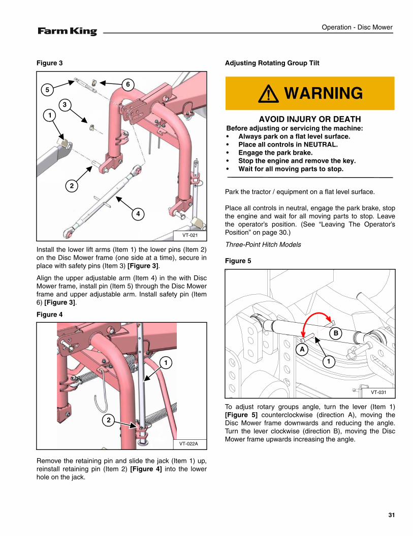
Figure 3
Install the lower lift arms (Item 1) the lower pins (Item 2)on the Disc Mower frame (one side at a time), secure inplace with safety pins (Item 3) [Figure 3].
Align the upper adjustable arm (Item 4) in the with DiscMower frame, install pin (Item 5) through the Disc Mowerframe and upper adjustable arm. Install safety pin (Item6) [Figure 3].
Figure 4
Remove the retaining pin and slide the jack (Item 1) up,reinstall retaining pin (Item 2) [Figure 4] into the lowerhole on the jack.
Adjusting Rotating Group Tilt
Park the tractor / equipment on a flat level surface.
Place all controls in neutral, engage the park brake, stopthe engine and wait for all moving parts to stop. Leavethe operator’s position. (See “Leaving The Operator’sPosition” on page 30.)
Three-Point Hitch Models
Figure 5
To adjust rotary groups angle, turn the lever (Item 1)[Figure 5] counterclockwise (direction A), moving theDisc Mower frame downwards and reducing the angle.Turn the lever clockwise (direction B), moving the DiscMower frame upwards increasing the angle.
VT-021
1
3
2
4
56
VT-022A
2
1
AVOID INJURY OR DEATHBefore adjusting or servicing the machine:• Always park on a flat level surface.• Place all controls in NEUTRAL.• Engage the park brake.• Stop the engine and remove the key.• Wait for all moving parts to stop.
VT-031
1
A
B
31
Operation - Disc Mower
Connecting The PTO Driveline (Three-Point Models)
NOTE: Clean and grease tractor’s PTO shaft and PTOdriveline coupling each time driveline isconnected.
Stop the engine and leave the operator’s position. (See“Leaving The Operator’s Position” on page 30.)
Remove the PTO driveline from the storage position (ifapplicable).
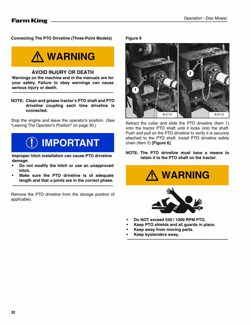
Figure 6
Retract the collar and slide the PTO driveline (Item 1)onto the tractor PTO shaft until it locks onto the shaft.Push and pull on the PTO driveline to verify it is securelyattached to the PTO shaft. Install PTO driveline safetychain (Item 2) [Figure 6].
NOTE: The PTO driveline must have a means toretain it to the PTO shaft on the tractor.
AVOID INJURY OR DEATHWarnings on the machine and in the manuals are foryour safety. Failure to obey warnings can causeserious injury or death.
Improper hitch installation can cause PTO drivelinedamage.• Do not modify the hitch or use an unapproved
hitch.• Make sure the PTO driveline is of adequate
length and that u-joints are in the correct phase.
B-0113B-0112
1
2
• Do NOT exceed 540 / 1000 RPM PTO.• Keep PTO shields and all guards in place.• Keep away from moving parts.• Keep bystanders away.
32
Operation - Disc Mower
PTO Driveline
PTO Driveline Length Check
NOTE: Due to variations in distances between tractorPTO shafts and implement input shafts,drivelines may need to be shortened or alonger shaft may be required. When fitting theimplement to the tractor, the PTO driveline,with telescoping sections, must be inspected.When the sections are at the mostcompressed operating position, the sectionsmust not “bottom out”. At its shortest length,there must be at least 2 in. (50,8 mm) ofclearance between each section end andopposite section end at the most compressedoperating position. When the sections are atthe most extended position, there must besufficient engagement between the sections.At its farthest operating extension, aminimum section engagement of 33% of shaftlength must be maintained.
PTO Driveline Bottoming Out Check
Stop the engine and leave the operator’s position. (See“Leaving The Operator’s Position” on page 30.)
Make sure the PTO driveline and all rotating componentshave come to a complete stop before leaving theoperator’s position (if applicable).
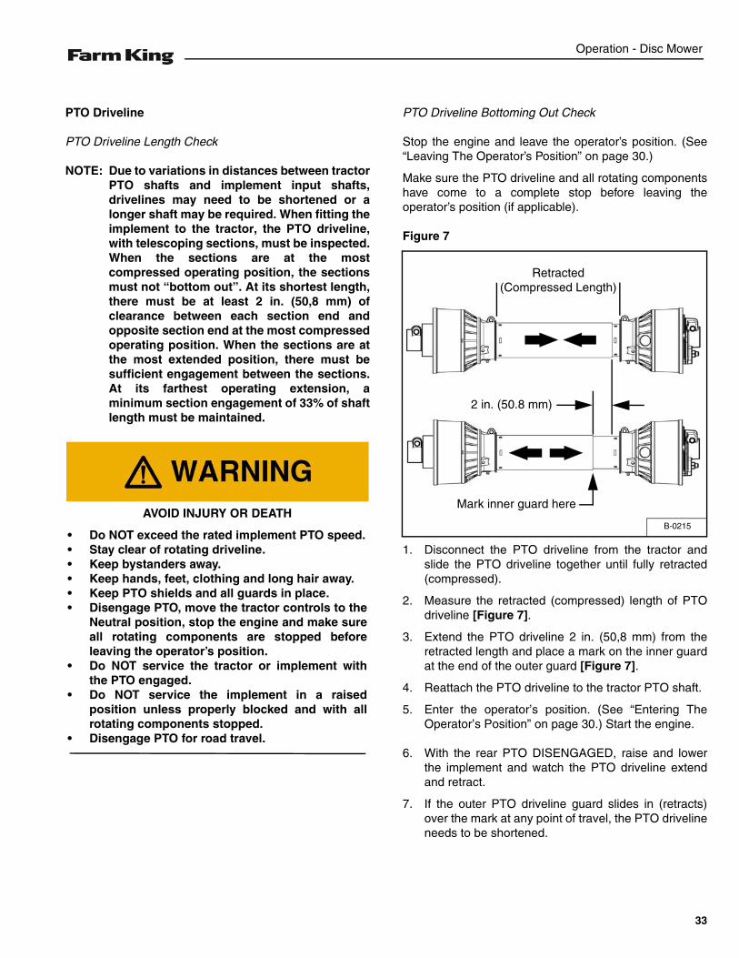
Figure 7
1. Disconnect the PTO driveline from the tractor andslide the PTO driveline together until fully retracted(compressed).
2. Measure the retracted (compressed) length of PTOdriveline [Figure 7].
3. Extend the PTO driveline 2 in. (50,8 mm) from theretracted length and place a mark on the inner guardat the end of the outer guard [Figure 7].
4. Reattach the PTO driveline to the tractor PTO shaft.
5. Enter the operator’s position. (See “Entering TheOperator’s Position” on page 30.) Start the engine.
6. With the rear PTO DISENGAGED, raise and lowerthe implement and watch the PTO driveline extendand retract.
7. If the outer PTO driveline guard slides in (retracts)over the mark at any point of travel, the PTO drivelineneeds to be shortened.
AVOID INJURY OR DEATH
• Do NOT exceed the rated implement PTO speed.• Stay clear of rotating driveline.• Keep bystanders away.• Keep hands, feet, clothing and long hair away.• Keep PTO shields and all guards in place.• Disengage PTO, move the tractor controls to the
Neutral position, stop the engine and make sureall rotating components are stopped beforeleaving the operator’s position.
• Do NOT service the tractor or implement withthe PTO engaged.
• Do NOT service the implement in a raisedposition unless properly blocked and with allrotating components stopped.
• Disengage PTO for road travel.
B-0215
Retracted (Compressed Length)
Mark inner guard here
2 in. (50.8 mm)
33
Operation - Disc Mower
Reducing The PTO Driveline Length
Stop the engine and leave the operator’s position. (See“Leaving The Operator’s Position” on page 30.)
Make sure the PTO driveline and all rotating componentshave come to a complete stop before leaving theoperator’s position.
Remove the PTO driveline from the tractor and place instorage position (if equipped).
Enter the operator’s position. (See “Entering TheOperator’s Position” on page 30.) Start the engine.
Raise or lower the disc to get the shortest distancebetween the tractor PTO shaft and disc gearbox PTOshaft.
Stop the engine and leave the operator’s position. (See“Leaving The Operator’s Position” on page 30.)
Pull the PTO driveline apart and reinstall each individualsection; one half to the tractor PTO shaft and one half tothe implement gearbox PTO shaft.
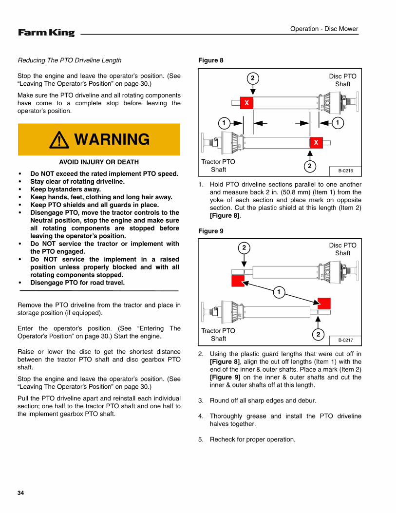
Figure 8
1. Hold PTO driveline sections parallel to one anotherand measure back 2 in. (50,8 mm) (Item 1) from theyoke of each section and place mark on oppositesection. Cut the plastic shield at this length (Item 2)[Figure 8].
Figure 9
2. Using the plastic guard lengths that were cut off in[Figure 8], align the cut off lengths (Item 1) with theend of the inner & outer shafts. Place a mark (Item 2)[Figure 9] on the inner & outer shafts and cut theinner & outer shafts off at this length.
3. Round off all sharp edges and debur.
4. Thoroughly grease and install the PTO drivelinehalves together.
5. Recheck for proper operation.
AVOID INJURY OR DEATH
• Do NOT exceed the rated implement PTO speed.• Stay clear of rotating driveline.• Keep bystanders away.• Keep hands, feet, clothing and long hair away.• Keep PTO shields and all guards in place.• Disengage PTO, move the tractor controls to the
Neutral position, stop the engine and make sureall rotating components are stopped beforeleaving the operator’s position.
• Do NOT service the tractor or implement withthe PTO engaged.
• Do NOT service the implement in a raisedposition unless properly blocked and with allrotating components stopped.
• Disengage PTO for road travel.
B-0216
Tractor PTO Shaft
Disc PTO Shaft
X
1
2
2
X
1
B-0217
Tractor PTO Shaft
Disc PTO Shaft
1
2
2
34
Operation - Disc Mower
PTO Driveline Engagement Check
Stop the engine and leave the operator’s position. (See“Leaving The Operator’s Position” on page 30.)
Make sure the PTO driveline and all rotating componentshave come to a complete stop before exiting the compacttractor.
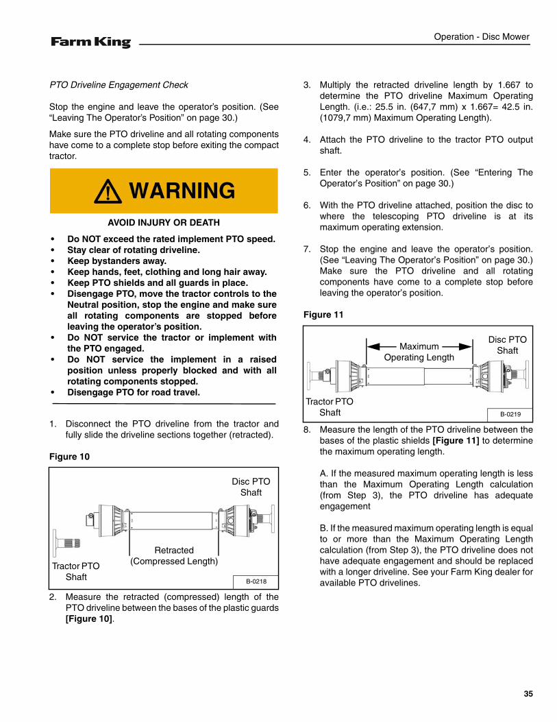
1. Disconnect the PTO driveline from the tractor andfully slide the driveline sections together (retracted).
Figure 10
2. Measure the retracted (compressed) length of thePTO driveline between the bases of the plastic guards[Figure 10].
3. Multiply the retracted driveline length by 1.667 todetermine the PTO driveline Maximum OperatingLength. (i.e.: 25.5 in. (647,7 mm) x 1.667= 42.5 in.(1079,7 mm) Maximum Operating Length).
4. Attach the PTO driveline to the tractor PTO outputshaft.
5. Enter the operator’s position. (See “Entering TheOperator’s Position” on page 30.)
6. With the PTO driveline attached, position the disc towhere the telescoping PTO driveline is at itsmaximum operating extension.
7. Stop the engine and leave the operator’s position.(See “Leaving The Operator’s Position” on page 30.)Make sure the PTO driveline and all rotatingcomponents have come to a complete stop beforeleaving the operator’s position.
Figure 11
8. Measure the length of the PTO driveline between thebases of the plastic shields [Figure 11] to determinethe maximum operating length.
A. If the measured maximum operating length is lessthan the Maximum Operating Length calculation(from Step 3), the PTO driveline has adequateengagement
B. If the measured maximum operating length is equalto or more than the Maximum Operating Lengthcalculation (from Step 3), the PTO driveline does nothave adequate engagement and should be replacedwith a longer driveline. See your Farm King dealer foravailable PTO drivelines.
AVOID INJURY OR DEATH
• Do NOT exceed the rated implement PTO speed.• Stay clear of rotating driveline.• Keep bystanders away.• Keep hands, feet, clothing and long hair away.• Keep PTO shields and all guards in place.• Disengage PTO, move the tractor controls to the
Neutral position, stop the engine and make sureall rotating components are stopped beforeleaving the operator’s position.
• Do NOT service the tractor or implement withthe PTO engaged.
• Do NOT service the implement in a raisedposition unless properly blocked and with allrotating components stopped.
• Disengage PTO for road travel.
B-0218
Tractor PTO Shaft
Disc PTO Shaft
Retracted (Compressed Length)
B-0219
Maximum Operating Length
Disc PTO Shaft
Tractor PTO Shaft
35
Operation - Disc Mower
Connecting Hydraulic Lines
NOTE: Make sure the quick couplers are fullyengaged. If the quick couplers do not fullyengage, check to see that the couplers are thesame size and type.
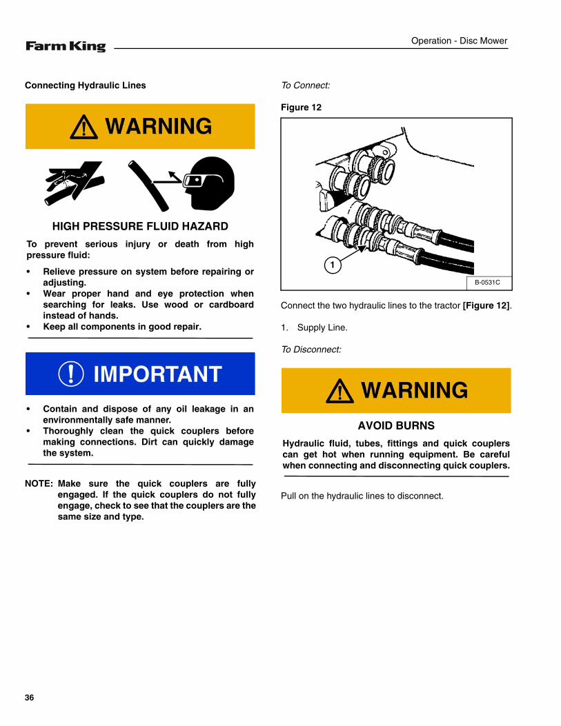
To Connect:
Figure 12
Connect the two hydraulic lines to the tractor [Figure 12].
1. Supply Line.
To Disconnect:
Pull on the hydraulic lines to disconnect.
HIGH PRESSURE FLUID HAZARD
To prevent serious injury or death from highpressure fluid:
• Relieve pressure on system before repairing oradjusting.
• Wear proper hand and eye protection whensearching for leaks. Use wood or cardboardinstead of hands.
• Keep all components in good repair.
• Contain and dispose of any oil leakage in anenvironmentally safe manner.
• Thoroughly clean the quick couplers beforemaking connections. Dirt can quickly damagethe system.
B-0531C
1
AVOID BURNS
Hydraulic fluid, tubes, fittings and quick couplerscan get hot when running equipment. Be carefulwhen connecting and disconnecting quick couplers.
36
Operation - Disc Mower
Operating Disc Mower (All Models)
Move to the operator’s position, start the engine andrelease the parking brake. (See “Entering The Operator’sPosition” on page 30.)
Move the tractor and Disc Mower to work area.
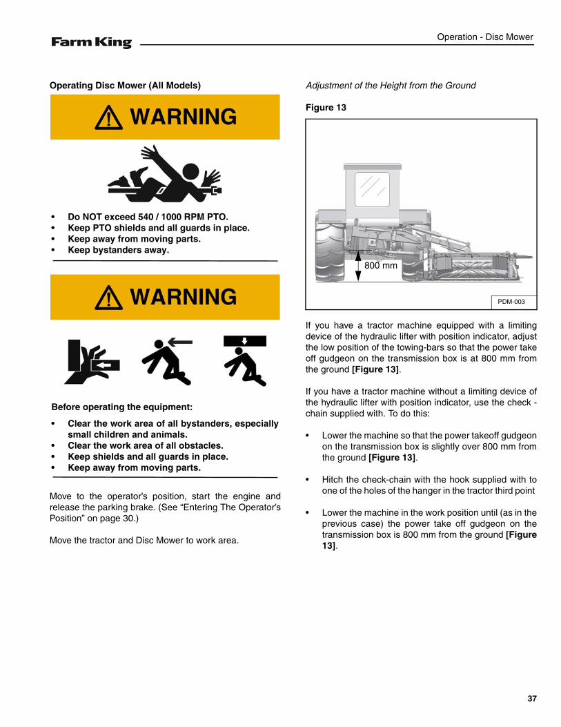
Adjustment of the Height from the Ground
Figure 13
If you have a tractor machine equipped with a limitingdevice of the hydraulic lifter with position indicator, adjustthe low position of the towing-bars so that the power takeoff gudgeon on the transmission box is at 800 mm fromthe ground [Figure 13].
If you have a tractor machine without a limiting device ofthe hydraulic lifter with position indicator, use the check -chain supplied with. To do this:
• Lower the machine so that the power takeoff gudgeonon the transmission box is slightly over 800 mm fromthe ground [Figure 13].
• Hitch the check-chain with the hook supplied with toone of the holes of the hanger in the tractor third point
• Lower the machine in the work position until (as in theprevious case) the power take off gudgeon on thetransmission box is 800 mm from the ground [Figure13].
• Do NOT exceed 540 / 1000 RPM PTO.• Keep PTO shields and all guards in place.• Keep away from moving parts.• Keep bystanders away.
Before operating the equipment:
• Clear the work area of all bystanders, especiallysmall children and animals.
• Clear the work area of all obstacles.• Keep shields and all guards in place.• Keep away from moving parts.
PDM-003
800 mm
37
Operation - Disc Mower
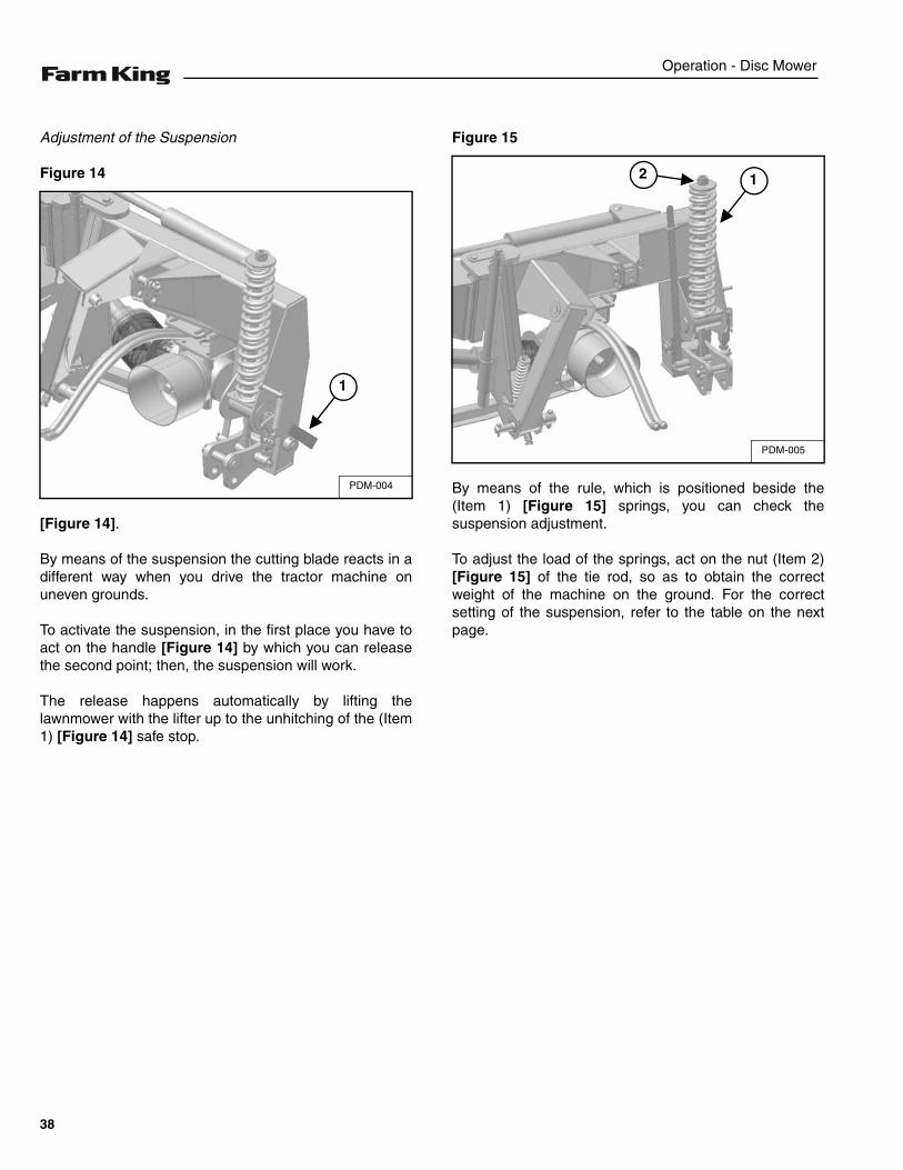
Adjustment of the Suspension
Figure 14
[Figure 14].
By means of the suspension the cutting blade reacts in adifferent way when you drive the tractor machine onuneven grounds.
To activate the suspension, in the first place you have toact on the handle [Figure 14] by which you can releasethe second point; then, the suspension will work.
The release happens automatically by lifting thelawnmower with the lifter up to the unhitching of the (Item1) [Figure 14] safe stop.
Figure 15
By means of the rule, which is positioned beside the(Item 1) [Figure 15] springs, you can check thesuspension adjustment.
To adjust the load of the springs, act on the nut (Item 2)[Figure 15] of the tie rod, so as to obtain the correctweight of the machine on the ground. For the correctsetting of the suspension, refer to the table on the nextpage.
PDM-004
1
PDM-005
12
38
Operation - Disc Mower
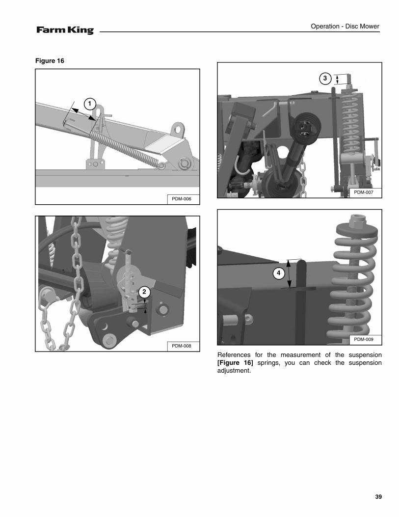
Figure 16
References for the measurement of the suspension[Figure 16] springs, you can check the suspensionadjustment.
PDM-006
1
PDM-008
2
PDM-007
3
PDM-009
4
39
Operation - Disc Mower
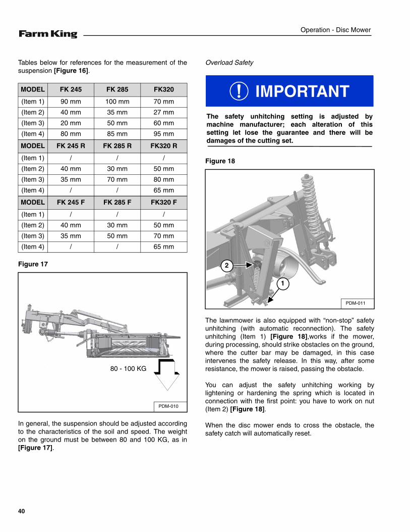
Tables below for references for the measurement of thesuspension [Figure 16].
Figure 17
In general, the suspension should be adjusted accordingto the characteristics of the soil and speed. The weighton the ground must be between 80 and 100 KG, as in[Figure 17].
Overload Safety
Figure 18
The lawnmower is also equipped with “non-stop” safetyunhitching (with automatic reconnection). The safetyunhitching (Item 1) [Figure 18],works if the mower,during processing, should strike obstacles on the ground,where the cutter bar may be damaged, in this caseintervenes the safety release. In this way, after someresistance, the mower is raised, passing the obstacle.
You can adjust the safety unhitching working bylightening or hardening the spring which is located inconnection with the first point: you have to work on nut(Item 2) [Figure 18].
When the disc mower ends to cross the obstacle, thesafety catch will automatically reset.
MODEL FK 245 FK 285 FK320
(Item 1) 90 mm 100 mm 70 mm
(Item 2) 40 mm 35 mm 27 mm
(Item 3) 20 mm 50 mm 60 mm
(Item 4) 80 mm 85 mm 95 mm
MODEL FK 245 R FK 285 R FK320 R
(Item 1) / / /
(Item 2) 40 mm 30 mm 50 mm
(Item 3) 35 mm 70 mm 80 mm
(Item 4) / / 65 mm
MODEL FK 245 F FK 285 F FK320 F
(Item 1) / / /
(Item 2) 40 mm 30 mm 50 mm
(Item 3) 35 mm 50 mm 70 mm
(Item 4) / / 65 mm
PDM-010
80 - 100 KG
The safety unhitching setting is adjusted bymachine manufacturer; each alteration of thissetting let lose the guarantee and there will bedamages of the cutting set.
PDM-011
1
2
40
Operation - Disc Mower
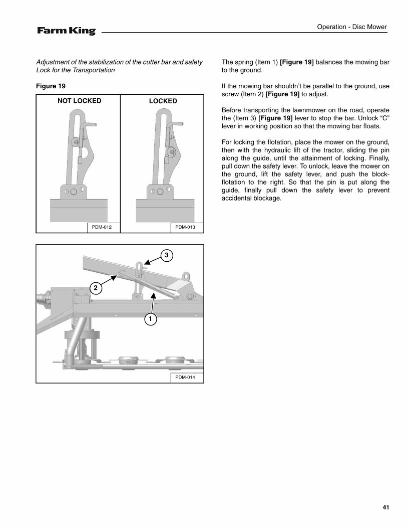
Adjustment of the stabilization of the cutter bar and safety Lock for the Transportation
Figure 19
The spring (Item 1) [Figure 19] balances the mowing barto the ground.
If the mowing bar shouldn’t be parallel to the ground, usescrew (Item 2) [Figure 19] to adjust.
Before transporting the lawnmower on the road, operatethe (Item 3) [Figure 19] lever to stop the bar. Unlock “C”lever in working position so that the mowing bar floats.
For locking the flotation, place the mower on the ground,then with the hydraulic lift of the tractor, sliding the pinalong the guide, until the attainment of locking. Finally,pull down the safety lever. To unlock, leave the mower onthe ground, lift the safety lever, and push the block-flotation to the right. So that the pin is put along theguide, finally pull down the safety lever to preventaccidental blockage.
PDM-013PDM-012
NOT LOCKED LOCKED
PDM-014
3
1
2
41
Operation - Disc Mower
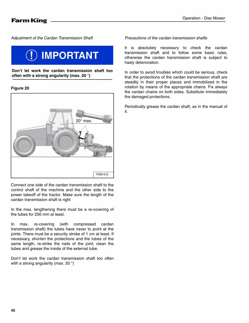
Adjustment of the Cardan Transmission Shaft
Figure 20
Connect one side of the cardan transmission shaft to thecontrol shaft of the machine and the other side to thepower takeoff of the tractor. Make sure the length of thecardan transmission shaft is right
In the max. lengthening there must be a re-covering ofthe tubes for 250 mm at least.
In max. re-covering (with compressed cardantransmission shaft) the tubes have never to point at thejoints. There must be a security stroke of 1 cm at least. Ifnecessary, shorten the protections and the tubes of thesame length, re-strike the nails of the joint, clean thetubes and grease the inside of the external tube.
Don’t let work the cardan transmission shaft too oftenwith a strong angularity (max. 20 °)
Precautions of the cardan transmission shafts
It is absolutely necessary to check the cardantransmission shaft and to follow some basic rules,otherwise the cardan transmission shaft is subject tohasty deterioration.
In order to avoid troubles which could be serious, checkthat the protections of the cardan transmission shaft aresteadily in their proper places and immobilized in therotation by means of the appropriate chains. Fix alwaysthe cardan chains on both sides. Substitute immediatelythe damaged protections.
Periodically grease the cardan shaft, as in the manual ofit.
Don’t let work the cardan transmission shaft toooften with a strong angularity (max. 20 °)
PDM-015
20° max.
42
Operation - Disc Mower
TRANSPORTING
Requirements
Comply with federal, state, local and provincial lawsregarding the transport of farm equipment on publicroadways.
Verify that the tractor / tow vehicle is approved fortransporting the equipment and that the equipment issecurely attached to the tractor / tow vehicle.
Verify safety chain is installed and properly connectedbefore transporting equipment.
Verify that the SMV (Slow Moving Vehicle) emblem, alllights and reflectors are clean and visible.
AVOID SERIOUS INJURY OR DEATH
Use of an unapproved hitch or tractor / tow vehiclecan result in loss of control, leading to seriousinjury or death.
Tractor / tow vehicle and hitch must have the ratedcapacity to tow equipment.
AVOID SERIOUS INJURY OR DEATH
Excess weight will greatly increase tractor stoppingdistance and may cause the operator to lose controlof the tractor or tow vehicle.
AVOID SERIOUS INJURY OR DEATH
Before putting the cutting set in the transportposition, wait for the complete stop of the Discrotation and send away everyone from themovement zone of the cutting set.
Towing Vehicle / Tractor must have adequatebraking capacity to safely control GVW trailing load.Do not tow over 20 mph (32 km/h). Towing Vehicle /Tractor unit should weigh approximately 67% ofGVW.
43
Operation - Disc Mower
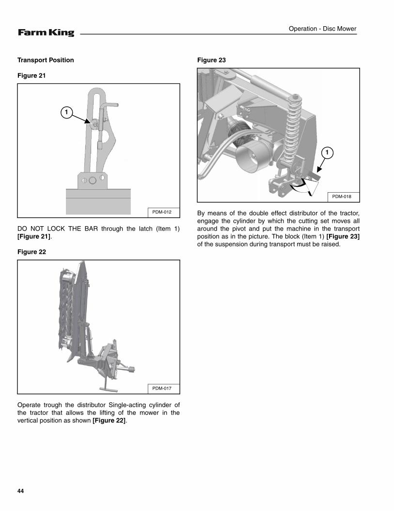
Transport Position
Figure 21
DO NOT LOCK THE BAR through the latch (Item 1)[Figure 21].
Figure 22
Operate trough the distributor Single-acting cylinder ofthe tractor that allows the lifting of the mower in thevertical position as shown [Figure 22].
Figure 23
By means of the double effect distributor of the tractor,engage the cylinder by which the cutting set moves allaround the pivot and put the machine in the transportposition as in the picture. The block (Item 1) [Figure 23]of the suspension during transport must be raised.
PDM-012
1
PDM-017
PDM-018
1
44
Operation - Disc Mower
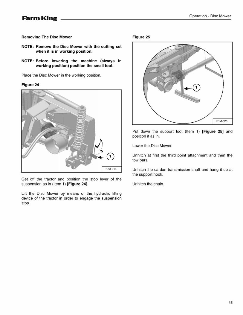
Removing The Disc Mower
NOTE: Remove the Disc Mower with the cutting setwhen it is in working position.
NOTE: Before lowering the machine (always inworking position) position the small foot.
Place the Disc Mower in the working position.
Figure 24
Get off the tractor and position the stop lever of thesuspension as in (Item 1) [Figure 24].
Lift the Disc Mower by means of the hydraulic liftingdevice of the tractor in order to engage the suspensionstop.
Figure 25
Put down the support foot (Item 1) [Figure 25] andposition it as in.
Lower the Disc Mower.
Unhitch at first the third point attachment and then thetow bars.
Unhitch the cardan transmission shaft and hang it up atthe support hook.
Unhitch the chain.
PDM-018
1
PDM-020
1
45

Operation - Disc Mower
46
Maintenance - Disc Mower
MAINTENANCE
TROUBLESHOOTING . . . . . . . . . . . . . . . . . . . . . . . . . . . . . . . . . . . . . . . . . . . . . . . . . . . . . . . . . . . 49Chart . . . . . . . . . . . . . . . . . . . . . . . . . . . . . . . . . . . . . . . . . . . . . . . . . . . . . . . . . . . . . . . . . . . . . . 49
SERVICE SCHEDULE . . . . . . . . . . . . . . . . . . . . . . . . . . . . . . . . . . . . . . . . . . . . . . . . . . . . . . . . . . . 50Maintenance Intervals . . . . . . . . . . . . . . . . . . . . . . . . . . . . . . . . . . . . . . . . . . . . . . . . . . . . . . . . . 50
CLEANING AND MAINTENANCE . . . . . . . . . . . . . . . . . . . . . . . . . . . . . . . . . . . . . . . . . . . . . . . . . . 52General Instructions . . . . . . . . . . . . . . . . . . . . . . . . . . . . . . . . . . . . . . . . . . . . . . . . . . . . . . . . . . 52Precautionary Measures To Be Adopted During The Cleaning And Maintenance Operations . .52Check The Cutting Blades . . . . . . . . . . . . . . . . . . . . . . . . . . . . . . . . . . . . . . . . . . . . . . . . . . . . . 53The Hydraulic System . . . . . . . . . . . . . . . . . . . . . . . . . . . . . . . . . . . . . . . . . . . . . . . . . . . . . . . . . 55Belt Adjustment Of The Machines With Conditioner . . . . . . . . . . . . . . . . . . . . . . . . . . . . . . . . . . 56Belt Replacing . . . . . . . . . . . . . . . . . . . . . . . . . . . . . . . . . . . . . . . . . . . . . . . . . . . . . . . . . . . . . . . 56Machines setting with conditioner . . . . . . . . . . . . . . . . . . . . . . . . . . . . . . . . . . . . . . . . . . . . . . . . 56Lubrication . . . . . . . . . . . . . . . . . . . . . . . . . . . . . . . . . . . . . . . . . . . . . . . . . . . . . . . . . . . . . . . . . 57Lubrication Locations . . . . . . . . . . . . . . . . . . . . . . . . . . . . . . . . . . . . . . . . . . . . . . . . . . . . . . . . . 59
STORAGE AND RETURN TO SERVICE . . . . . . . . . . . . . . . . . . . . . . . . . . . . . . . . . . . . . . . . . . . . . 59Storage . . . . . . . . . . . . . . . . . . . . . . . . . . . . . . . . . . . . . . . . . . . . . . . . . . . . . . . . . . . . . . . . . . . . 59Return To Service . . . . . . . . . . . . . . . . . . . . . . . . . . . . . . . . . . . . . . . . . . . . . . . . . . . . . . . . . . . .60
47

Maintenance - Disc Mower
48
Maintenance - Disc Mower
TROUBLESHOOTING
Chart
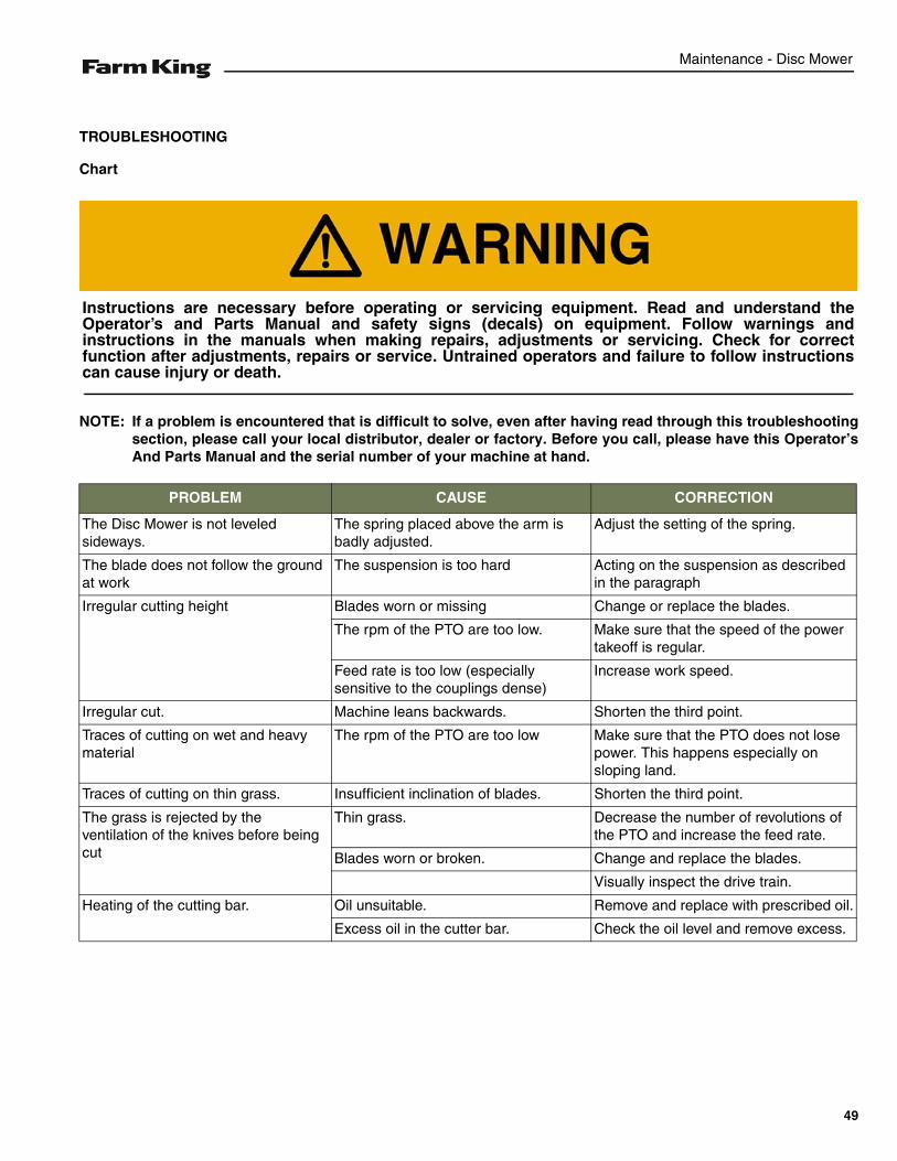
NOTE: If a problem is encountered that is difficult to solve, even after having read through this troubleshootingsection, please call your local distributor, dealer or factory. Before you call, please have this Operator’sAnd Parts Manual and the serial number of your machine at hand.
PROBLEM CAUSE CORRECTION
The Disc Mower is not leveledsideways.
The spring placed above the arm is badly adjusted.
Adjust the setting of the spring.
The blade does not follow the ground at work
The suspension is too hard Acting on the suspension as described in the paragraph
Irregular cutting height Blades worn or missing Change or replace the blades.
The rpm of the PTO are too low. Make sure that the speed of the powertakeoff is regular.
Feed rate is too low (especially sensitive to the couplings dense)
Increase work speed.
Irregular cut. Machine leans backwards. Shorten the third point.
Traces of cutting on wet and heavy material
The rpm of the PTO are too low Make sure that the PTO does not losepower. This happens especially on sloping land.
Traces of cutting on thin grass. Insufficient inclination of blades. Shorten the third point.
The grass is rejected by the ventilation of the knives before being cut
Thin grass. Decrease the number of revolutions of the PTO and increase the feed rate.
Blades worn or broken. Change and replace the blades.
Visually inspect the drive train.
Heating of the cutting bar. Oil unsuitable. Remove and replace with prescribed oil.
Excess oil in the cutter bar. Check the oil level and remove excess.
Instructions are necessary before operating or servicing equipment. Read and understand theOperator’s and Parts Manual and safety signs (decals) on equipment. Follow warnings andinstructions in the manuals when making repairs, adjustments or servicing. Check for correctfunction after adjustments, repairs or service. Untrained operators and failure to follow instructionscan cause injury or death.
49
Maintenance - Disc Mower
SERVICE SCHEDULE
Maintenance Intervals
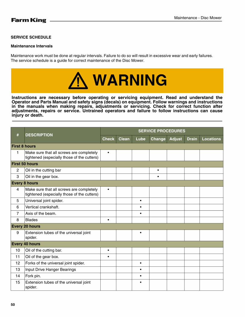
Maintenance work must be done at regular intervals. Failure to do so will result in excessive wear and early failures.The service schedule is a guide for correct maintenance of the Disc Mower.
# DESCRIPTIONSERVICE PROCEDURES
Check Clean Lube Change Adjust Drain Locations
First 8 hours
1 Make sure that all screws are completely tightened (especially those of the cutters)
•
First 50 hours
2 Oil in the cutting bar •
3 Oil in the gear box. •
Every 8 hours
4 Make sure that all screws are completely tightened (especially those of the cutters)
•
5 Universal joint spider. •
6 Vertical crankshaft. •
7 Axis of the beam. •
8 Blades •
Every 20 hours
9 Extension tubes of the universal joint spider.
•
Every 40 hours
10 Oil of the cutting bar. •
11 Oil of the gear box. •
12 Forks of the universal joint spider. •
13 Input Drive Hanger Bearings •
14 Fork pin. •
15 Extension tubes of the universal joint spider.
•
Instructions are necessary before operating or servicing equipment. Read and understand theOperator and Parts Manual and safety signs (decals) on equipment. Follow warnings and instructionsin the manuals when making repairs, adjustments or servicing. Check for correct function afteradjustments, repairs or service. Untrained operators and failure to follow instructions can causeinjury or death.
50

Maintenance - Disc Mower
After Each Season
16 Oil of the cutting bar. •
17 Oil of the gear box. •
# DESCRIPTIONSERVICE PROCEDURES
Check Clean Lube Change Adjust Drain Locations
51
Maintenance - Disc Mower
CLEANING AND MAINTENANCE
General Instructions
The cleaning and maintenance of the machine includescleaning and greasing of the mobile parts etc.
These operations must be carried out following theinstructions of this manual and, when required, usingpersonal protective equipment (gloves, shoes, etc.)
The operations that may be performed at the premisesmay be brought back to the routine maintenanceoperations foreseen by this manual.
The machine during periods when it is not used shouldbe parked in a dry and protected area.
After a period of inactivity, is to remember to perform acheck in a service center. For any type of maintenance,put the mower on a flat and rigid surface; if you need totake action on the mower, remove it from the tractor.
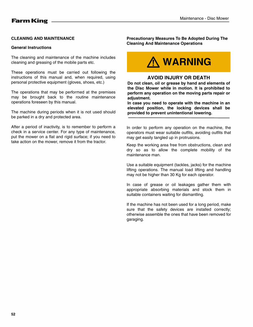
Precautionary Measures To Be Adopted During The Cleaning And Maintenance Operations
In order to perform any operation on the machine, theoperators must wear suitable outfits, avoiding outfits thatmay get easily tangled up in protrusions.
Keep the working area free from obstructions, clean anddry so as to allow the complete mobility of themaintenance man.
Use a suitable equipment (tackles, jacks) for the machinelifting operations. The manual load lifting and handlingmay not be higher than 30 Kg for each operator.
In case of grease or oil leakages gather them withappropriate absorbing materials and stock them insuitable containers waiting for dismantling.
If the machine has not been used for a long period, makesure that the safety devices are installed correctly;otherwise assemble the ones that have been removed forgaraging.
AVOID INJURY OR DEATHDo not clean, oil or grease by hand and elements ofthe Disc Mower while in motion. It is prohibited toperform any operation on the moving parts repair oradjustment.In case you need to operate with the machine in anelevated position, the locking devices shall beprovided to prevent unintentional lowering.
52
Maintenance - Disc Mower
Check The Cutting Blades
Check them systematically before using the mower
To get a quality mowing and a use security, check thecutting blades carefully and systematically. You have tosubstitute the cutting blades in the following cases:
1. Damaged cutting blades.
Because of an uneven ground the cutting blades canhave clefts or deformations, which cause:
- an increase of accident risks,
- a reduction in mowing quality,
- deterioration risks of the Disc holder.
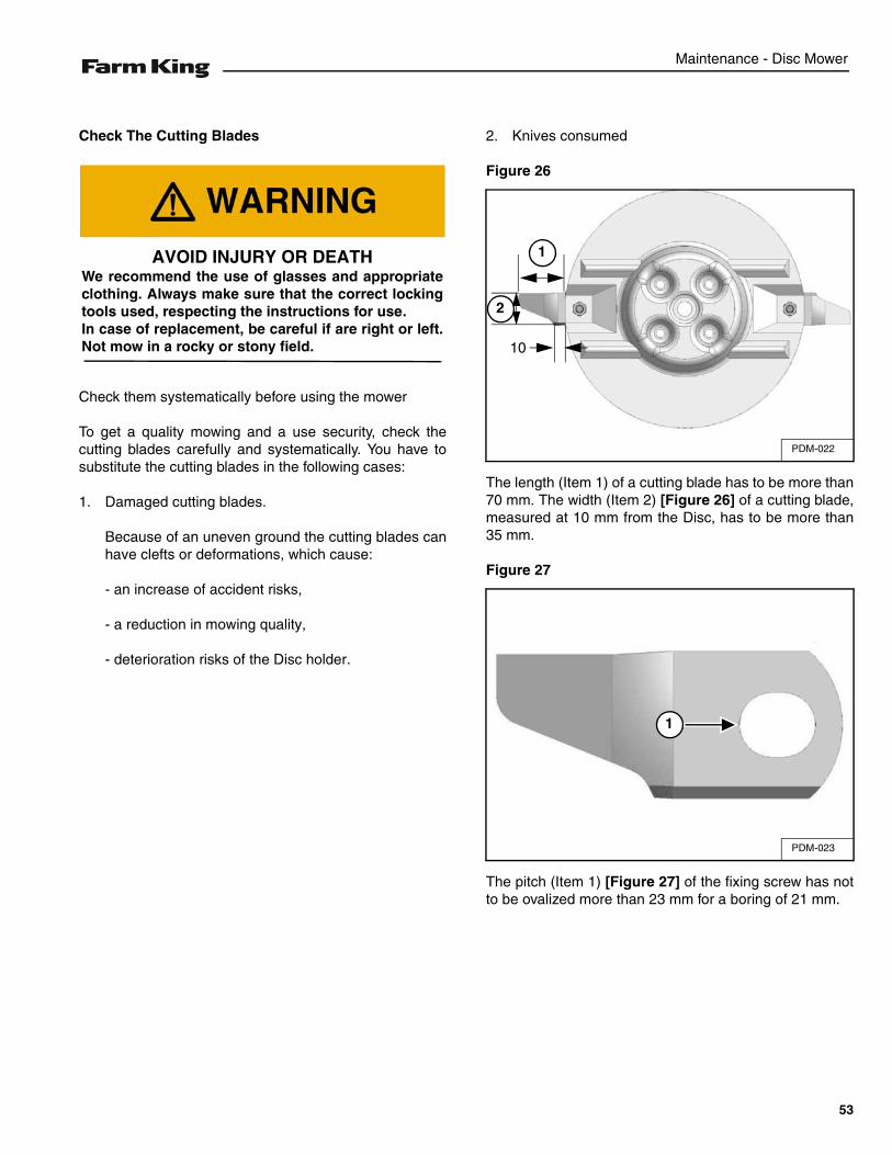
2. Knives consumed
Figure 26
The length (Item 1) of a cutting blade has to be more than70 mm. The width (Item 2) [Figure 26] of a cutting blade,measured at 10 mm from the Disc, has to be more than35 mm.
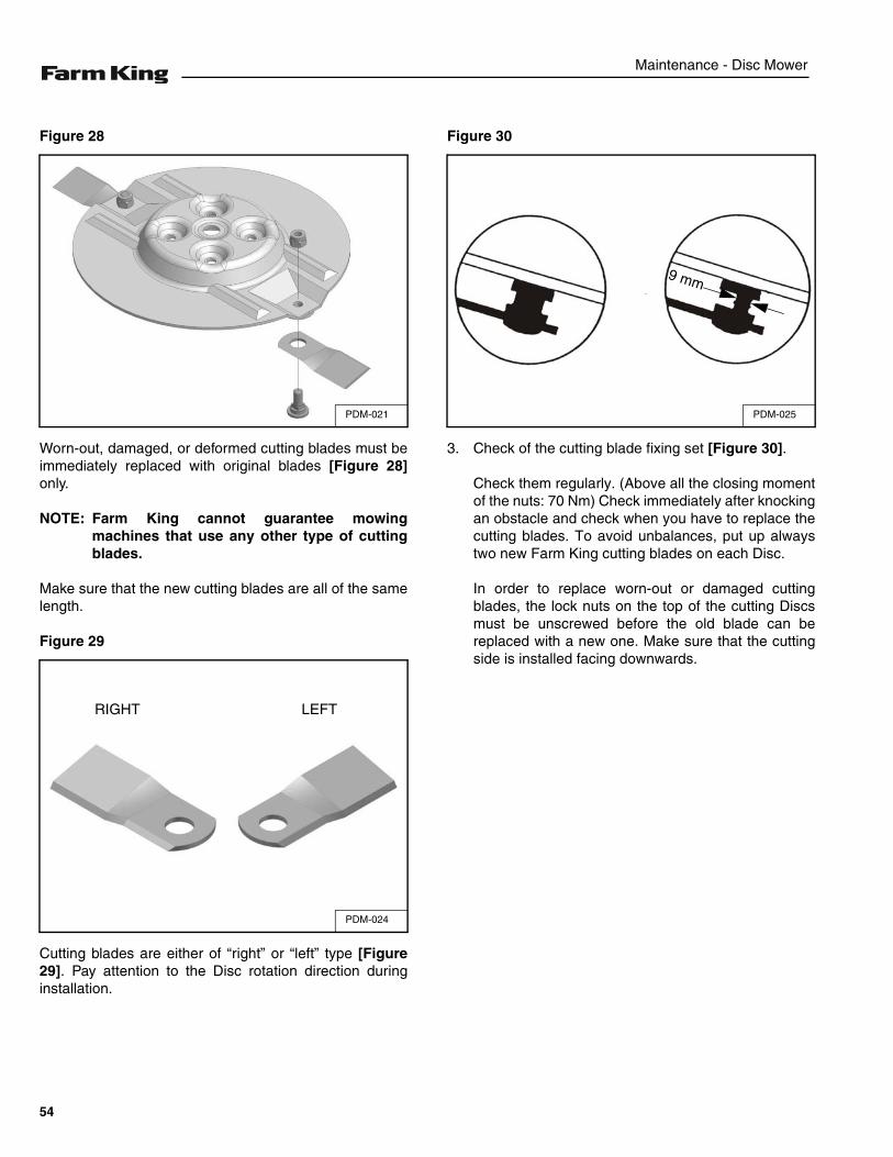
Figure 27
The pitch (Item 1) [Figure 27] of the fixing screw has notto be ovalized more than 23 mm for a boring of 21 mm.
AVOID INJURY OR DEATHWe recommend the use of glasses and appropriateclothing. Always make sure that the correct lockingtools used, respecting the instructions for use.In case of replacement, be careful if are right or left.Not mow in a rocky or stony field.
PDM-022
1
2
10
PDM-023
1
53
Maintenance - Disc Mower
Figure 28
Worn-out, damaged, or deformed cutting blades must beimmediately replaced with original blades [Figure 28]only.
NOTE: Farm King cannot guarantee mowingmachines that use any other type of cuttingblades.
Make sure that the new cutting blades are all of the samelength.
Figure 29
Cutting blades are either of “right” or “left” type [Figure29]. Pay attention to the Disc rotation direction duringinstallation.
Figure 30
3. Check of the cutting blade fixing set [Figure 30].
Check them regularly. (Above all the closing momentof the nuts: 70 Nm) Check immediately after knockingan obstacle and check when you have to replace thecutting blades. To avoid unbalances, put up alwaystwo new Farm King cutting blades on each Disc.
In order to replace worn-out or damaged cuttingblades, the lock nuts on the top of the cutting Discsmust be unscrewed before the old blade can bereplaced with a new one. Make sure that the cuttingside is installed facing downwards.
PDM-021
PDM-024
RIGHT LEFT
PDM-025
9 mm
54
Maintenance - Disc Mower
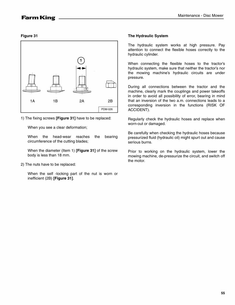
Figure 31
1) The fixing screws [Figure 31] have to be replaced:
When you see a clear deformation;
When the head-wear reaches the bearingcircumference of the cutting blades;
When the diameter (Item 1) [Figure 31] of the screwbody is less than 18 mm.
2) The nuts have to be replaced:
When the self -locking part of the nut is worn orinefficient (2B) [Figure 31].
The Hydraulic System
The hydraulic system works at high pressure. Payattention to connect the flexible hoses correctly to thehydraulic cylinder.
When connecting the flexible hoses to the tractor’shydraulic system, make sure that neither the tractor’s northe mowing machine’s hydraulic circuits are underpressure.
During all connections between the tractor and themachine, clearly mark the couplings and power takeoffsin order to avoid all possibility of error, bearing in mindthat an inversion of the two a.m. connections leads to acorresponding inversion in the functions (RISK OFACCIDENT).
Regularly check the hydraulic hoses and replace whenworn-out or damaged.
Be carefully when checking the hydraulic hoses becausepressurized fluid (hydraulic oil) might spurt out and causeserious burns.
Prior to working on the hydraulic system, lower themowing machine, de-pressurize the circuit, and switch offthe motor.
PDM-026
1A 1B 2A 2B
1
55
Maintenance - Disc Mower
Belt Adjustment Of The Machines With Conditioner
Figure 32
The tightness of the v-belts must be checked frequently,especially when they are new.
Whenever one v-belt is observed to be defective, theentire set must be replaced. The correct tensioning of thebelts is performed by a tension spring [Figure 32].
If it is necessary, tighten the nut leaving 1 mm so thatbetween the inner cylinder of the spring and the same[Figure 32], there is 1 mm.
Belt Replacing
When it becomes necessary to replace all the belts:make sure to take off the cover and loosen the tensioner.Once you have replaced all the belts, close the cover andtension as described [Figure 32].
Machines setting with conditioner
Machines settings with conditioner F
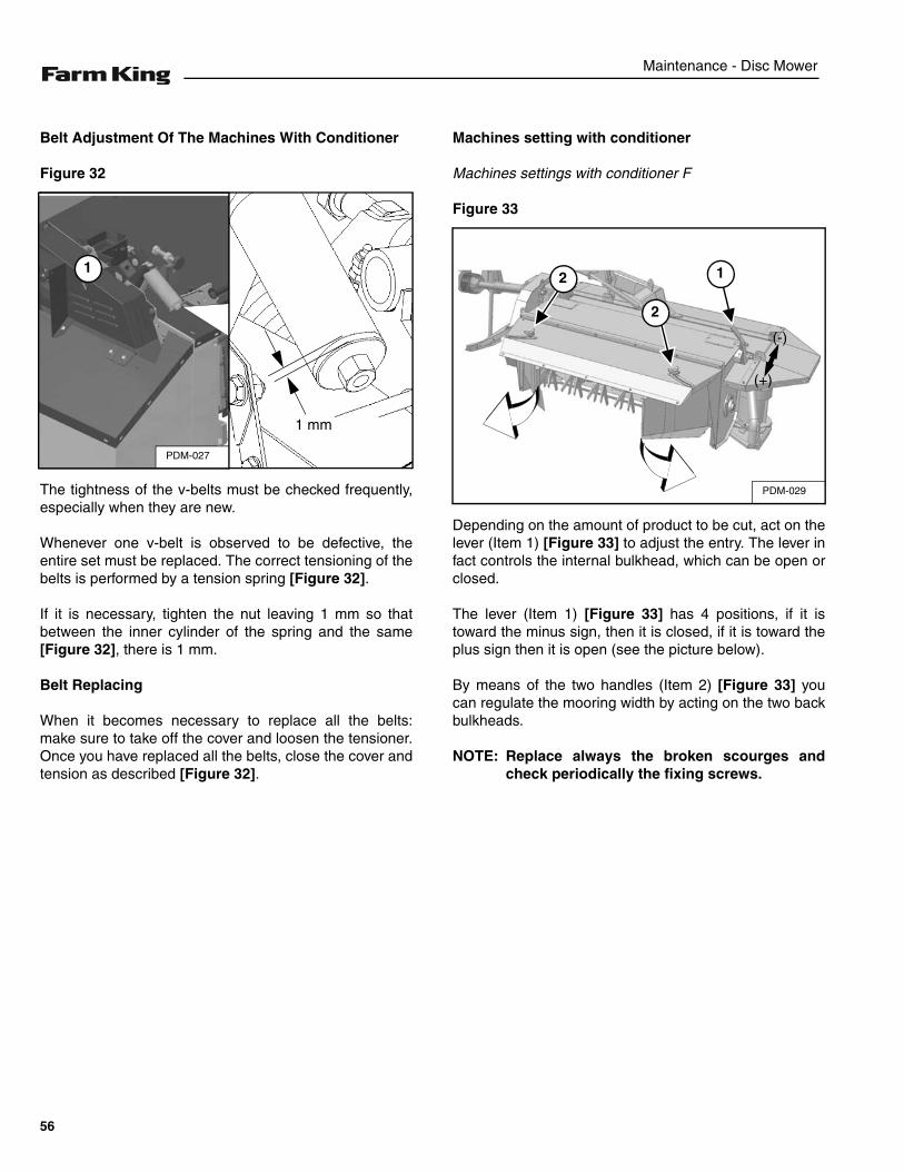
Figure 33
Depending on the amount of product to be cut, act on thelever (Item 1) [Figure 33] to adjust the entry. The lever infact controls the internal bulkhead, which can be open orclosed.
The lever (Item 1) [Figure 33] has 4 positions, if it istoward the minus sign, then it is closed, if it is toward theplus sign then it is open (see the picture below).
By means of the two handles (Item 2) [Figure 33] youcan regulate the mooring width by acting on the two backbulkheads.
NOTE: Replace always the broken scourges andcheck periodically the fixing screws.
PDM-028
1
1 mm
PDM-027
1
PDM-029
1
2
2
(+)
(-)
56
Maintenance - Disc Mower
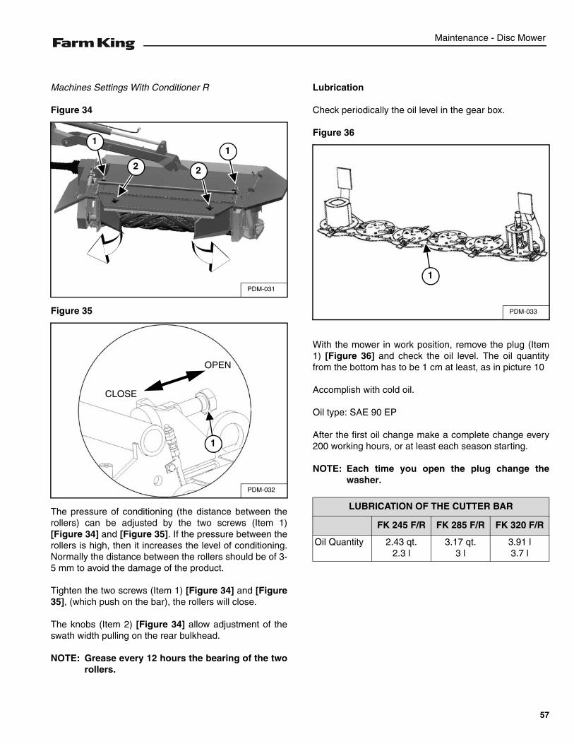
Machines Settings With Conditioner R
Figure 34
Figure 35
The pressure of conditioning (the distance between therollers) can be adjusted by the two screws (Item 1)[Figure 34] and [Figure 35]. If the pressure between therollers is high, then it increases the level of conditioning.Normally the distance between the rollers should be of 3-5 mm to avoid the damage of the product.
Tighten the two screws (Item 1) [Figure 34] and [Figure35], (which push on the bar), the rollers will close.
The knobs (Item 2) [Figure 34] allow adjustment of theswath width pulling on the rear bulkhead.
NOTE: Grease every 12 hours the bearing of the tworollers.
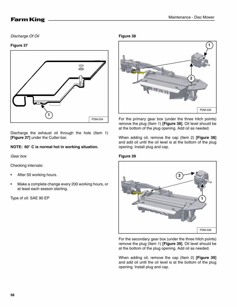
Lubrication
Check periodically the oil level in the gear box.
Figure 36
With the mower in work position, remove the plug (Item1) [Figure 36] and check the oil level. The oil quantityfrom the bottom has to be 1 cm at least, as in picture 10
Accomplish with cold oil.
Oil type: SAE 90 EP
After the first oil change make a complete change every200 working hours, or at least each season starting.
NOTE: Each time you open the plug change thewasher.
PDM-031
1
22
1
PDM-032
CLOSE
OPEN
1
LUBRICATION OF THE CUTTER BAR
FK 245 F/R FK 285 F/R FK 320 F/R
Oil Quantity 2.43 qt.2.3 l
3.17 qt.3 l
3.91 l3.7 l
PDM-033
1
57
Maintenance - Disc Mower
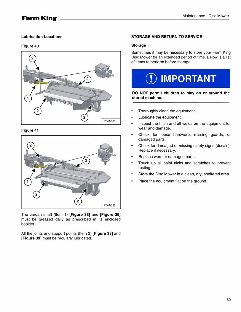
Discharge Of Oil
Figure 37
Discharge the exhaust oil through the hole (Item 1)[Figure 37] under the Cutter-bar.
NOTE: 60° C is normal hot in working situation.
Gear box
Checking intervals:
• After 50 working hours.
• Make a complete change every 200 working hours, orat least each season starting.
Type of oil: SAE 90 EP
Figure 38
For the primary gear box (under the three hitch points)remove the plug (Item 1) [Figure 38]. Oil level should beat the bottom of the plug opening. Add oil as needed.
When adding oil, remove the cap (Item 2) [Figure 38]and add oil until the oil level is at the bottom of the plugopening. Install plug and cap.
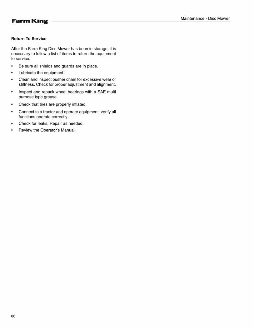
Figure 39
For the secondary gear box (under the three hitch points)remove the plug (Item 1) [Figure 39]. Oil level should beat the bottom of the plug opening. Add oil as needed.
When adding oil, remove the cap (Item 2) [Figure 39]and add oil until the oil level is at the bottom of the plugopening. Install plug and cap.
PDM-034
1PDM-035
2
1
PDM-036
1
2
58
Maintenance - Disc Mower
Lubrication Locations
Figure 40
Figure 41
The cardan shaft (Item 1) [Figure 38] and [Figure 39]must be greased daily as prescribed in its enclosedbooklet.
All the joints and support points (Item 2) [Figure 38] and[Figure 39] must be regularly lubricated.
STORAGE AND RETURN TO SERVICE
Storage
Sometimes it may be necessary to store your Farm KingDisc Mower for an extended period of time. Below is a listof items to perform before storage.
• Thoroughly clean the equipment.
• Lubricate the equipment.
• Inspect the hitch and all welds on the equipment forwear and damage.
• Check for loose hardware, missing guards, ordamaged parts.
• Check for damaged or missing safety signs (decals).Replace if necessary.
• Replace worn or damaged parts.
• Touch up all paint nicks and scratches to preventrusting.
• Store the Disc Mower in a clean, dry, sheltered area.
• Place the equipment flat on the ground.
PDM-035
2
2
2
2
1
PDM-036
1
2
2
2
2
DO NOT permit children to play on or around thestored machine.
59
Maintenance - Disc Mower
Return To Service
After the Farm King Disc Mower has been in storage, it isnecessary to follow a list of items to return the equipmentto service.
• Be sure all shields and guards are in place.
• Lubricate the equipment.
• Clean and inspect pusher chain for excessive wear orstiffness. Check for proper adjustment and alignment.
• Inspect and repack wheel bearings with a SAE multipurpose type grease.
• Check that tires are properly inflated.
• Connect to a tractor and operate equipment, verify allfunctions operate correctly.
• Check for leaks. Repair as needed.
• Review the Operator’s Manual.
60
Parts Identification - Disc Mower
PARTS IDENTIFICATION
GENERAL INFORMATION . . . . . . . . . . . . . . . . . . . . . . . . . . . . . . . . . . . . . . . . . . . . . . . . . . . . . . . 63
THREE POINT HITCH . . . . . . . . . . . . . . . . . . . . . . . . . . . . . . . . . . . . . . . . . . . . . . . . . . . . . . . . . . . 64
FRAME GROUP . . . . . . . . . . . . . . . . . . . . . . . . . . . . . . . . . . . . . . . . . . . . . . . . . . . . . . . . . . . . . . . . 68F Group . . . . . . . . . . . . . . . . . . . . . . . . . . . . . . . . . . . . . . . . . . . . . . . . . . . . . . . . . . . . . . . . . . . . 68R Group . . . . . . . . . . . . . . . . . . . . . . . . . . . . . . . . . . . . . . . . . . . . . . . . . . . . . . . . . . . . . . . . . . . 72Normal Group . . . . . . . . . . . . . . . . . . . . . . . . . . . . . . . . . . . . . . . . . . . . . . . . . . . . . . . . . . . . . . . 76
CUTTER BAR . . . . . . . . . . . . . . . . . . . . . . . . . . . . . . . . . . . . . . . . . . . . . . . . . . . . . . . . . . . . . . . . . 82
FINGER CONDITIONER . . . . . . . . . . . . . . . . . . . . . . . . . . . . . . . . . . . . . . . . . . . . . . . . . . . . . . . . . 86
ROLLER CONDITIONER . . . . . . . . . . . . . . . . . . . . . . . . . . . . . . . . . . . . . . . . . . . . . . . . . . . . . . . . . 90
TRANSMISSION . . . . . . . . . . . . . . . . . . . . . . . . . . . . . . . . . . . . . . . . . . . . . . . . . . . . . . . . . . . . . . .96F Group . . . . . . . . . . . . . . . . . . . . . . . . . . . . . . . . . . . . . . . . . . . . . . . . . . . . . . . . . . . . . . . . . . . . 96R Group . . . . . . . . . . . . . . . . . . . . . . . . . . . . . . . . . . . . . . . . . . . . . . . . . . . . . . . . . . . . . . . . . . . 98
PROTECTION . . . . . . . . . . . . . . . . . . . . . . . . . . . . . . . . . . . . . . . . . . . . . . . . . . . . . . . . . . . . . . . . 100F Group . . . . . . . . . . . . . . . . . . . . . . . . . . . . . . . . . . . . . . . . . . . . . . . . . . . . . . . . . . . . . . . . . . . 100R Group . . . . . . . . . . . . . . . . . . . . . . . . . . . . . . . . . . . . . . . . . . . . . . . . . . . . . . . . . . . . . . . . . . 102Normal Group . . . . . . . . . . . . . . . . . . . . . . . . . . . . . . . . . . . . . . . . . . . . . . . . . . . . . . . . . . . . . . 104
SWATHER . . . . . . . . . . . . . . . . . . . . . . . . . . . . . . . . . . . . . . . . . . . . . . . . . . . . . . . . . . . . . . . . . . . 106
GEAR BOXES . . . . . . . . . . . . . . . . . . . . . . . . . . . . . . . . . . . . . . . . . . . . . . . . . . . . . . . . . . . . . . . . 108Part 32031052 . . . . . . . . . . . . . . . . . . . . . . . . . . . . . . . . . . . . . . . . . . . . . . . . . . . . . . . . . . . . . 110Part 32031070 . . . . . . . . . . . . . . . . . . . . . . . . . . . . . . . . . . . . . . . . . . . . . . . . . . . . . . . . . . . . . 112
CARDAN SHAFTS . . . . . . . . . . . . . . . . . . . . . . . . . . . . . . . . . . . . . . . . . . . . . . . . . . . . . . . . . . . . . 114Part 989931015 540 RPM . . . . . . . . . . . . . . . . . . . . . . . . . . . . . . . . . . . . . . . . . . . . . . . . . . . . 114Part 989931044 1000 RPM . . . . . . . . . . . . . . . . . . . . . . . . . . . . . . . . . . . . . . . . . . . . . . . . . . . 116Part 989931018 . . . . . . . . . . . . . . . . . . . . . . . . . . . . . . . . . . . . . . . . . . . . . . . . . . . . . . . . . . . . 118
61

Parts Identification - Disc Mower
62
Parts - Disc Mower
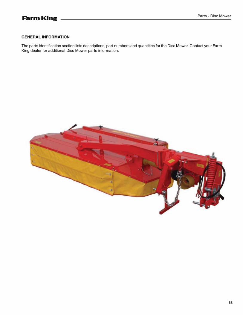
GENERAL INFORMATION
The parts identification section lists descriptions, part numbers and quantities for the Disc Mower. Contact your FarmKing dealer for additional Disc Mower parts information.
63
Parts - Disc Mower
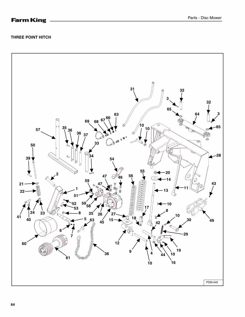
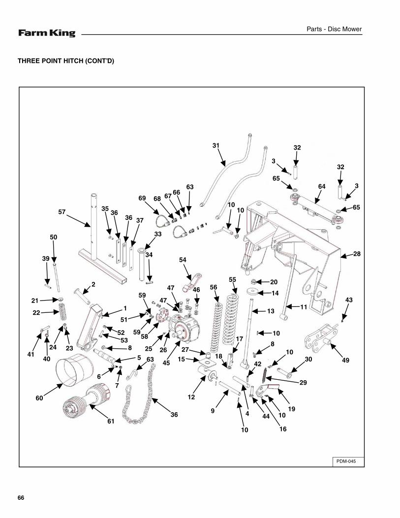
THREE POINT HITCH
PDM-045
1
50
2
39
21
22
4140
24 23
5253
63
51
5958
25 26
60
6136
45 1527
12
9
10
4 44 1019
42
29
3010
8
10
4918
17
46 5655
13
14
20
1143
28
65
364
32
32
3
65
1010
31
6366676869
33
3454
373636
35
47
4759
57
8
5
76
16
64
Parts - Disc Mower
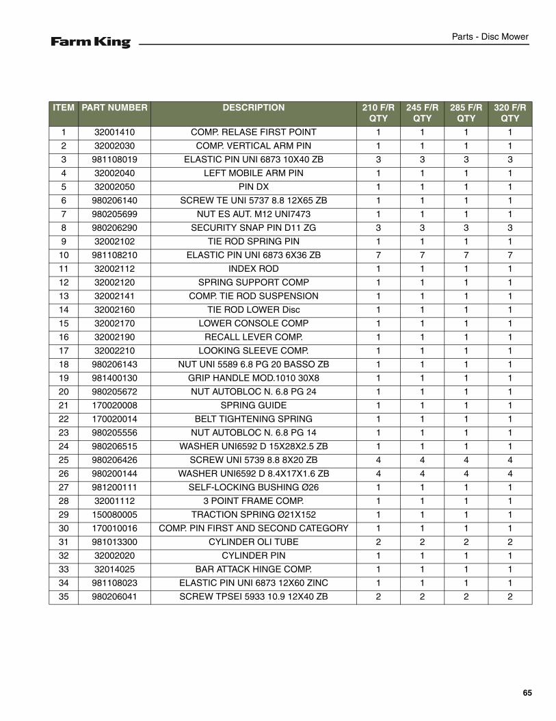
ITEM PART NUMBER DESCRIPTION 210 F/R QTY
245 F/R QTY
285 F/R QTY
320 F/R QTY
1 32001410 COMP. RELASE FIRST POINT 1 1 1 1
2 32002030 COMP. VERTICAL ARM PIN 1 1 1 1
3 981108019 ELASTIC PIN UNI 6873 10X40 ZB 3 3 3 3
4 32002040 LEFT MOBILE ARM PIN 1 1 1 1
5 32002050 PIN DX 1 1 1 1
6 980206140 SCREW TE UNI 5737 8.8 12X65 ZB 1 1 1 1
7 980205699 NUT ES AUT. M12 UNI7473 1 1 1 1
8 980206290 SECURITY SNAP PIN D11 ZG 3 3 3 3
9 32002102 TIE ROD SPRING PIN 1 1 1 1
10 981108210 ELASTIC PIN UNI 6873 6X36 ZB 7 7 7 7
11 32002112 INDEX ROD 1 1 1 1
12 32002120 SPRING SUPPORT COMP 1 1 1 1
13 32002141 COMP. TIE ROD SUSPENSION 1 1 1 1
14 32002160 TIE ROD LOWER Disc 1 1 1 1
15 32002170 LOWER CONSOLE COMP 1 1 1 1
16 32002190 RECALL LEVER COMP. 1 1 1 1
17 32002210 LOOKING SLEEVE COMP. 1 1 1 1
18 980206143 NUT UNI 5589 6.8 PG 20 BASSO ZB 1 1 1 1
19 981400130 GRIP HANDLE MOD.1010 30X8 1 1 1 1
20 980205672 NUT AUTOBLOC N. 6.8 PG 24 1 1 1 1
21 170020008 SPRING GUIDE 1 1 1 1
22 170020014 BELT TIGHTENING SPRING 1 1 1 1
23 980205556 NUT AUTOBLOC N. 6.8 PG 14 1 1 1 1
24 980206515 WASHER UNI6592 D 15X28X2.5 ZB 1 1 1 1
25 980206426 SCREW UNI 5739 8.8 8X20 ZB 4 4 4 4
26 980200144 WASHER UNI6592 D 8.4X17X1.6 ZB 4 4 4 4
27 981200111 SELF-LOCKING BUSHING Ø26 1 1 1 1
28 32001112 3 POINT FRAME COMP. 1 1 1 1
29 150080005 TRACTION SPRING Ø21X152 1 1 1 1
30 170010016 COMP. PIN FIRST AND SECOND CATEGORY 1 1 1 1
31 981013300 CYLINDER OLI TUBE 2 2 2 2
32 32002020 CYLINDER PIN 1 1 1 1
33 32014025 BAR ATTACK HINGE COMP. 1 1 1 1
34 981108023 ELASTIC PIN UNI 6873 12X60 ZINC 1 1 1 1
35 980206041 SCREW TPSEI 5933 10.9 12X40 ZB 2 2 2 2
65
Parts - Disc Mower
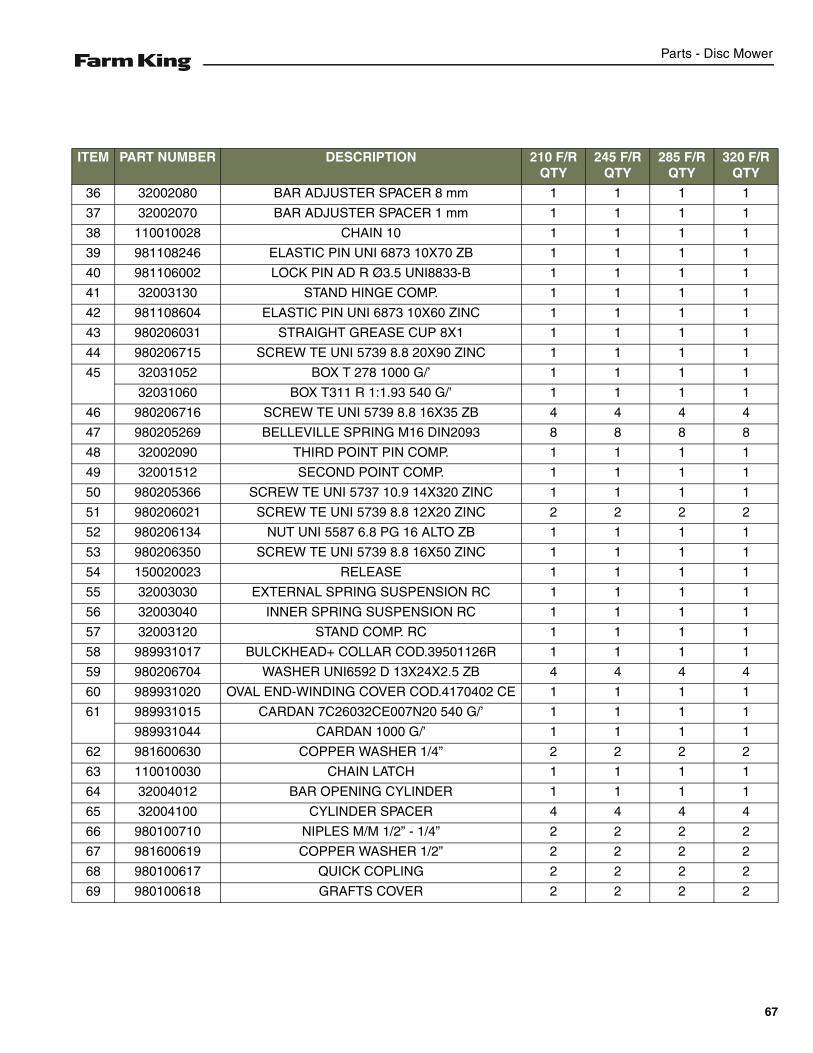
THREE POINT HITCH (CONT’D)
PDM-045
1
50
2
39
21
22
4140
24 23
5253
63
51
5958
25 26
60
6136
45 1527
12
9
10
4 44 1019
42
29
3010
8
10
4918
17
46 5655
13
14
20
1143
28
65
364
32
32
3
65
1010
31
6366676869
33
3454
373636
35
47
4759
57
8
5
76
16
66
Parts - Disc Mower
ITEM PART NUMBER DESCRIPTION 210 F/R QTY
245 F/R QTY
285 F/R QTY
320 F/R QTY
36 32002080 BAR ADJUSTER SPACER 8 mm 1 1 1 1
37 32002070 BAR ADJUSTER SPACER 1 mm 1 1 1 1
38 110010028 CHAIN 10 1 1 1 1
39 981108246 ELASTIC PIN UNI 6873 10X70 ZB 1 1 1 1
40 981106002 LOCK PIN AD R Ø3.5 UNI8833-B 1 1 1 1
41 32003130 STAND HINGE COMP. 1 1 1 1
42 981108604 ELASTIC PIN UNI 6873 10X60 ZINC 1 1 1 1
43 980206031 STRAIGHT GREASE CUP 8X1 1 1 1 1
44 980206715 SCREW TE UNI 5739 8.8 20X90 ZINC 1 1 1 1
45 32031052 BOX T 278 1000 G/’ 1 1 1 1
32031060 BOX T311 R 1:1.93 540 G/’ 1 1 1 1
46 980206716 SCREW TE UNI 5739 8.8 16X35 ZB 4 4 4 4
47 980205269 BELLEVILLE SPRING M16 DIN2093 8 8 8 8
48 32002090 THIRD POINT PIN COMP. 1 1 1 1
49 32001512 SECOND POINT COMP. 1 1 1 1
50 980205366 SCREW TE UNI 5737 10.9 14X320 ZINC 1 1 1 1
51 980206021 SCREW TE UNI 5739 8.8 12X20 ZINC 2 2 2 2
52 980206134 NUT UNI 5587 6.8 PG 16 ALTO ZB 1 1 1 1
53 980206350 SCREW TE UNI 5739 8.8 16X50 ZINC 1 1 1 1
54 150020023 RELEASE 1 1 1 1
55 32003030 EXTERNAL SPRING SUSPENSION RC 1 1 1 1
56 32003040 INNER SPRING SUSPENSION RC 1 1 1 1
57 32003120 STAND COMP. RC 1 1 1 1
58 989931017 BULCKHEAD+ COLLAR COD.39501126R 1 1 1 1
59 980206704 WASHER UNI6592 D 13X24X2.5 ZB 4 4 4 4
60 989931020 OVAL END-WINDING COVER COD.4170402 CE 1 1 1 1
61 989931015 CARDAN 7C26032CE007N20 540 G/’ 1 1 1 1
989931044 CARDAN 1000 G/’ 1 1 1 1
62 981600630 COPPER WASHER 1/4” 2 2 2 2
63 110010030 CHAIN LATCH 1 1 1 1
64 32004012 BAR OPENING CYLINDER 1 1 1 1
65 32004100 CYLINDER SPACER 4 4 4 4
66 980100710 NIPLES M/M 1/2” - 1/4” 2 2 2 2
67 981600619 COPPER WASHER 1/2” 2 2 2 2
68 980100617 QUICK COPLING 2 2 2 2
69 980100618 GRAFTS COVER 2 2 2 2
67
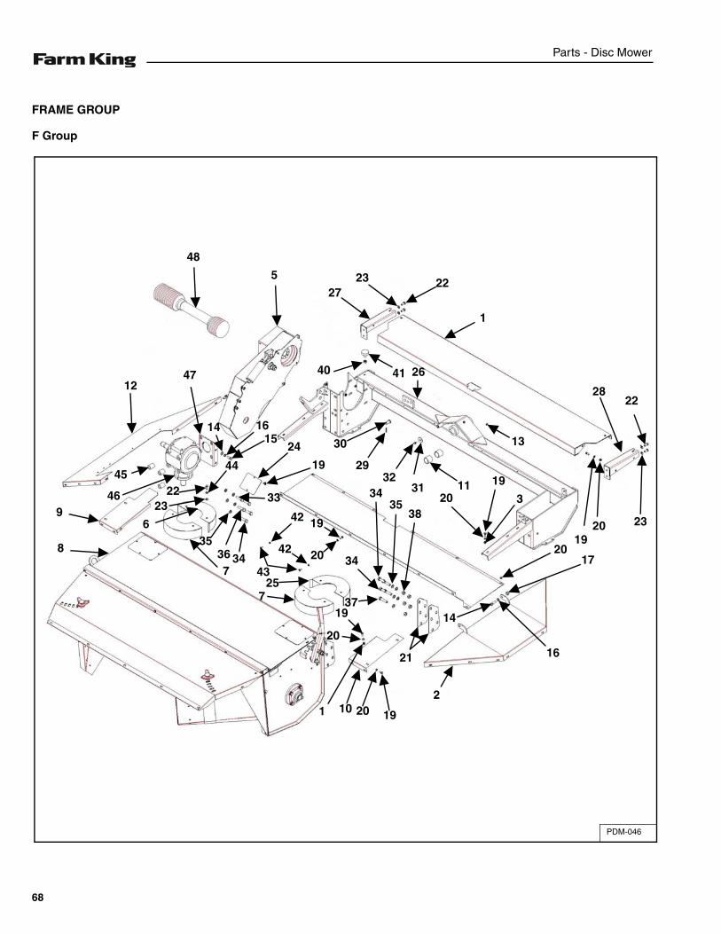
Parts - Disc Mower
FRAME GROUP
F Group
PDM-046
48
5
4712
9
8
46
45
2322
14 1615
44
24
19
33
356
736 34
43
42 19
2042
257
1
20
19
10 20 19
21
2
3835
34
34
37
16
14
1720
3
1920
11
13
3132
29
30
40 41 26
2723 22
1
22
232019
28
68
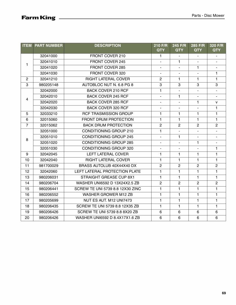
Parts - Disc Mower
ITEM PART NUMBER DESCRIPTION 210 F/R QTY
245 F/R QTY
285 F/R QTY
320 F/R QTY
1
32041000 FRONT COVER 210 1 - - -
32041010 FRONT COVER 245 - 1 - -
32041020 FRONT COVER 285 - - 1 -
32041030 FRONT COVER 320 - - - 1
2 32041210 RIGHT LATERAL COVER 2 1 1 1
3 980205148 AUTOBLOC NUT N. 6.8 PG 8 3 3 3 3
4
32042000 BACK COVER 210 RCF 1 - - -
32042010 BACK COVER 245 RCF - 1 - -
32042020 BACK COVER 285 RCF - - 1 v
32042030 BACK COVER 320 RCF - - - 1
5 32033210 RCF TRASMISSION GROUP 1 1 1 1
6 32015060 FRONT DRUM PROTECTION 1 1 1 1
7 32015062 BACK DRUM PROTECTION 2 2 2 2
8
32051000 CONDITIONING GROUP 210 1 - - -
32051010 CONDITIONING GROUP 245 - 1 - -
32051020 CONDITIONING GROUP 285 - - 1 -
32051030 CONDITIONING GROUP 320 - - - 1
9 32042045 LEFT LATERAL COVER 1 1 1 1
10 32042040 RIGHT LATERAL COVER 1 1 1 1
11 981700029 BRASS AUTOLUB 40X44X40 DX 2 2 2 2
12 32042060 LEFT LATERAL PROTECTION PLATE 1 1 1 1
13 980206031 STRAIGHT GREASE CUP 8X1 1 1 1 1
14 980206704 WASHER UNI6592 D 13X24X2.5 ZB 2 2 2 2
15 980206441 SCREW TE UNI 5739 8.8 12X30 ZINC 1 1 1 1
16 980206552 WASHER GROWER M12 ZB 1 1 1 1
17 980205699 NUT ES AUT. M12 UNI7473 1 1 1 1
18 980206435 SCREW TE UNI 5739 8.8 12X35 ZB 1 1 1 1
19 980206426 SCREW TE UNI 5739 8.8 8X20 ZB 6 6 6 6
20 980206426 WASHER UNI6592 D 8.4X17X1.6 ZB 6 6 6 6
69
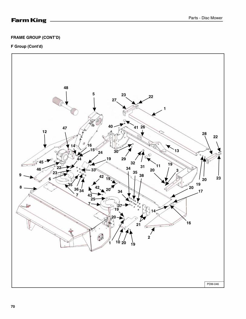
Parts - Disc Mower
FRAME GROUP (CONT’D)
F Group (Cont’d)
PDM-046
48
5
4712
9
8
46
45
2322
14 1615
44
24
19
33
356
736 34
43
42 19
2042
257
1
20
19
10 20 19
21
2
3835
34
34
37
16
14
1720
3
1920
11
13
3132
29
30
40 41 26
2723 22
1
22
232019
28
70
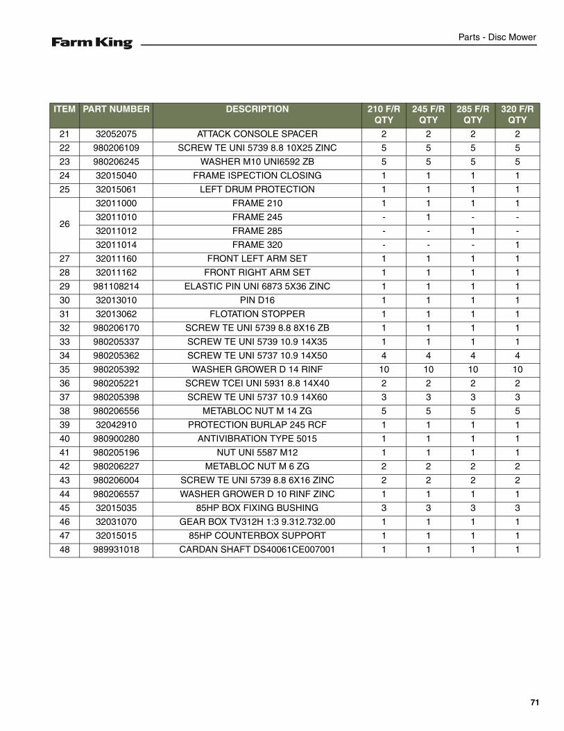
Parts - Disc Mower
ITEM PART NUMBER DESCRIPTION 210 F/R QTY
245 F/R QTY
285 F/R QTY
320 F/R QTY
21 32052075 ATTACK CONSOLE SPACER 2 2 2 2
22 980206109 SCREW TE UNI 5739 8.8 10X25 ZINC 5 5 5 5
23 980206245 WASHER M10 UNI6592 ZB 5 5 5 5
24 32015040 FRAME ISPECTION CLOSING 1 1 1 1
25 32015061 LEFT DRUM PROTECTION 1 1 1 1
26
32011000 FRAME 210 1 1 1 1
32011010 FRAME 245 - 1 - -
32011012 FRAME 285 - - 1 -
32011014 FRAME 320 - - - 1
27 32011160 FRONT LEFT ARM SET 1 1 1 1
28 32011162 FRONT RIGHT ARM SET 1 1 1 1
29 981108214 ELASTIC PIN UNI 6873 5X36 ZINC 1 1 1 1
30 32013010 PIN D16 1 1 1 1
31 32013062 FLOTATION STOPPER 1 1 1 1
32 980206170 SCREW TE UNI 5739 8.8 8X16 ZB 1 1 1 1
33 980205337 SCREW TE UNI 5739 10.9 14X35 1 1 1 1
34 980205362 SCREW TE UNI 5737 10.9 14X50 4 4 4 4
35 980205392 WASHER GROWER D 14 RINF 10 10 10 10
36 980205221 SCREW TCEI UNI 5931 8.8 14X40 2 2 2 2
37 980205398 SCREW TE UNI 5737 10.9 14X60 3 3 3 3
38 980206556 METABLOC NUT M 14 ZG 5 5 5 5
39 32042910 PROTECTION BURLAP 245 RCF 1 1 1 1
40 980900280 ANTIVIBRATION TYPE 5015 1 1 1 1
41 980205196 NUT UNI 5587 M12 1 1 1 1
42 980206227 METABLOC NUT M 6 ZG 2 2 2 2
43 980206004 SCREW TE UNI 5739 8.8 6X16 ZINC 2 2 2 2
44 980206557 WASHER GROWER D 10 RINF ZINC 1 1 1 1
45 32015035 85HP BOX FIXING BUSHING 3 3 3 3
46 32031070 GEAR BOX TV312H 1:3 9.312.732.00 1 1 1 1
47 32015015 85HP COUNTERBOX SUPPORT 1 1 1 1
48 989931018 CARDAN SHAFT DS40061CE007001 1 1 1 1
71
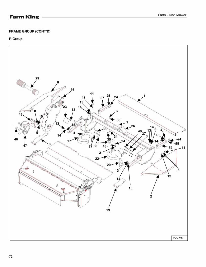
Parts - Disc Mower
FRAME GROUP (CONT’D)
R Group
PDM-047
19
15
2
14
13
20
22
21
435
17
4
243
3740
267
33
32
1314 3 4
13
14 2425
28
12
8
11
1242527
4445
1314
1323
1513
14
36
629
9
10
848
1847
46
38
3837
3534
72
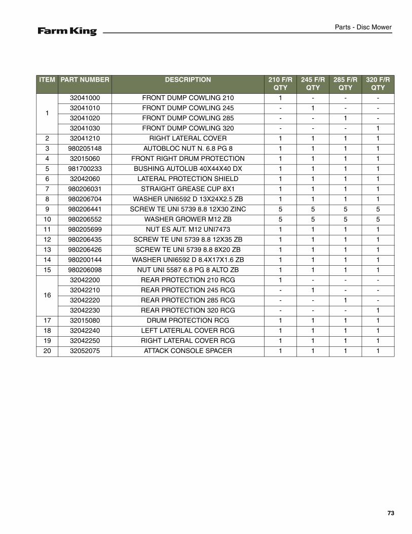
Parts - Disc Mower
ITEM PART NUMBER DESCRIPTION 210 F/R QTY
245 F/R QTY
285 F/R QTY
320 F/R QTY
1
32041000 FRONT DUMP COWLING 210 1 - - -
32041010 FRONT DUMP COWLING 245 - 1 - -
32041020 FRONT DUMP COWLING 285 - - 1 -
32041030 FRONT DUMP COWLING 320 - - - 1
2 32041210 RIGHT LATERAL COVER 1 1 1 1
3 980205148 AUTOBLOC NUT N. 6.8 PG 8 1 1 1 1
4 32015060 FRONT RIGHT DRUM PROTECTION 1 1 1 1
5 981700233 BUSHING AUTOLUB 40X44X40 DX 1 1 1 1
6 32042060 LATERAL PROTECTION SHIELD 1 1 1 1
7 980206031 STRAIGHT GREASE CUP 8X1 1 1 1 1
8 980206704 WASHER UNI6592 D 13X24X2.5 ZB 1 1 1 1
9 980206441 SCREW TE UNI 5739 8.8 12X30 ZINC 5 5 5 5
10 980206552 WASHER GROWER M12 ZB 5 5 5 5
11 980205699 NUT ES AUT. M12 UNI7473 1 1 1 1
12 980206435 SCREW TE UNI 5739 8.8 12X35 ZB 1 1 1 1
13 980206426 SCREW TE UNI 5739 8.8 8X20 ZB 1 1 1 1
14 980200144 WASHER UNI6592 D 8.4X17X1.6 ZB 1 1 1 1
15 980206098 NUT UNI 5587 6.8 PG 8 ALTO ZB 1 1 1 1
16
32042200 REAR PROTECTION 210 RCG 1 - - -
32042210 REAR PROTECTION 245 RCG - 1 - -
32042220 REAR PROTECTION 285 RCG - - 1 -
32042230 REAR PROTECTION 320 RCG - - - 1
17 32015080 DRUM PROTECTION RCG 1 1 1 1
18 32042240 LEFT LATERLAL COVER RCG 1 1 1 1
19 32042250 RIGHT LATERAL COVER RCG 1 1 1 1
20 32052075 ATTACK CONSOLE SPACER 1 1 1 1
73

Parts - Disc Mower
FRAME GROUP (CONT’D)
R Group (Cont’d)
PDM-047
19
15
2
14
13
20
22
21
435
17
4
243
3740
267
33
32
1314 3 4
13
14 2425
28
12
8
11
1242527
4445
1314
1323
1513
14
36
629
9
10
848
1847
46
38
3837
3534
74
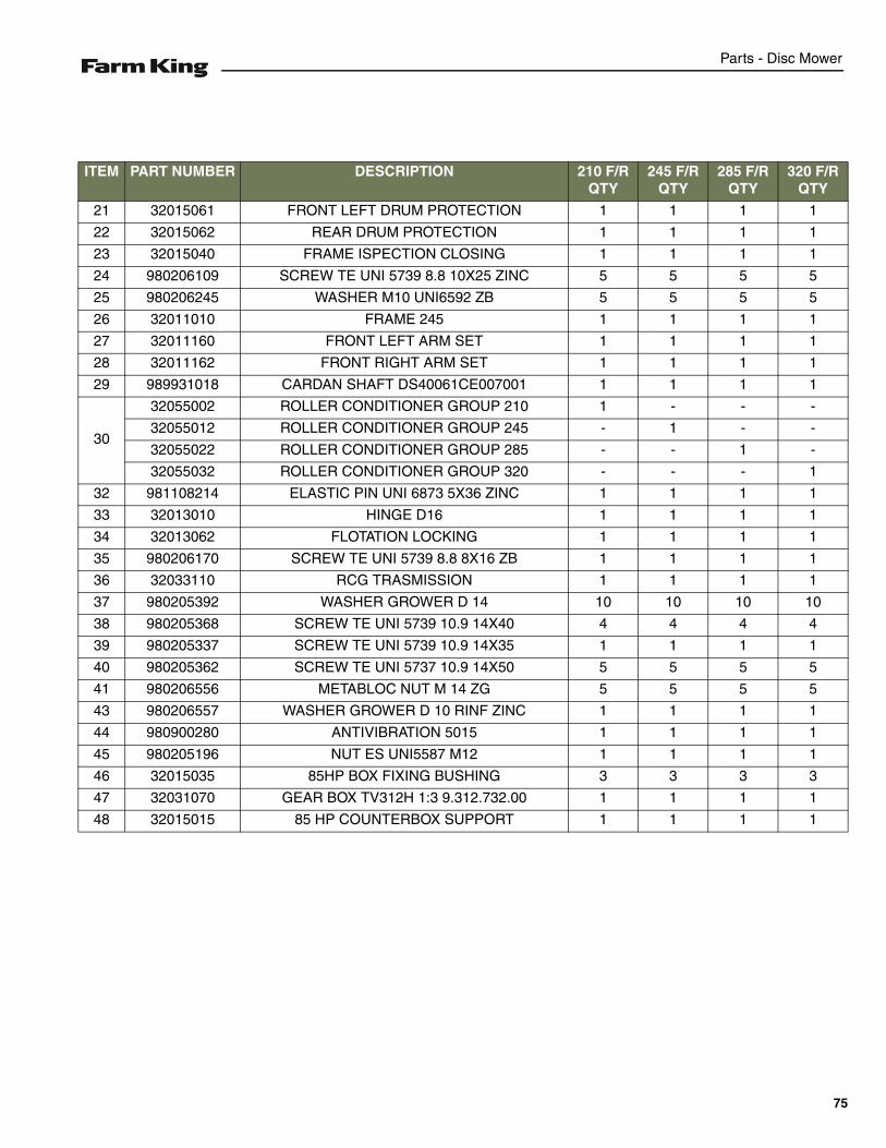
Parts - Disc Mower
ITEM PART NUMBER DESCRIPTION 210 F/R QTY
245 F/R QTY
285 F/R QTY
320 F/R QTY
21 32015061 FRONT LEFT DRUM PROTECTION 1 1 1 1
22 32015062 REAR DRUM PROTECTION 1 1 1 1
23 32015040 FRAME ISPECTION CLOSING 1 1 1 1
24 980206109 SCREW TE UNI 5739 8.8 10X25 ZINC 5 5 5 5
25 980206245 WASHER M10 UNI6592 ZB 5 5 5 5
26 32011010 FRAME 245 1 1 1 1
27 32011160 FRONT LEFT ARM SET 1 1 1 1
28 32011162 FRONT RIGHT ARM SET 1 1 1 1
29 989931018 CARDAN SHAFT DS40061CE007001 1 1 1 1
30
32055002 ROLLER CONDITIONER GROUP 210 1 - - -
32055012 ROLLER CONDITIONER GROUP 245 - 1 - -
32055022 ROLLER CONDITIONER GROUP 285 - - 1 -
32055032 ROLLER CONDITIONER GROUP 320 - - - 1
32 981108214 ELASTIC PIN UNI 6873 5X36 ZINC 1 1 1 1
33 32013010 HINGE D16 1 1 1 1
34 32013062 FLOTATION LOCKING 1 1 1 1
35 980206170 SCREW TE UNI 5739 8.8 8X16 ZB 1 1 1 1
36 32033110 RCG TRASMISSION 1 1 1 1
37 980205392 WASHER GROWER D 14 10 10 10 10
38 980205368 SCREW TE UNI 5739 10.9 14X40 4 4 4 4
39 980205337 SCREW TE UNI 5739 10.9 14X35 1 1 1 1
40 980205362 SCREW TE UNI 5737 10.9 14X50 5 5 5 5
41 980206556 METABLOC NUT M 14 ZG 5 5 5 5
43 980206557 WASHER GROWER D 10 RINF ZINC 1 1 1 1
44 980900280 ANTIVIBRATION 5015 1 1 1 1
45 980205196 NUT ES UNI5587 M12 1 1 1 1
46 32015035 85HP BOX FIXING BUSHING 3 3 3 3
47 32031070 GEAR BOX TV312H 1:3 9.312.732.00 1 1 1 1
48 32015015 85 HP COUNTERBOX SUPPORT 1 1 1 1
75
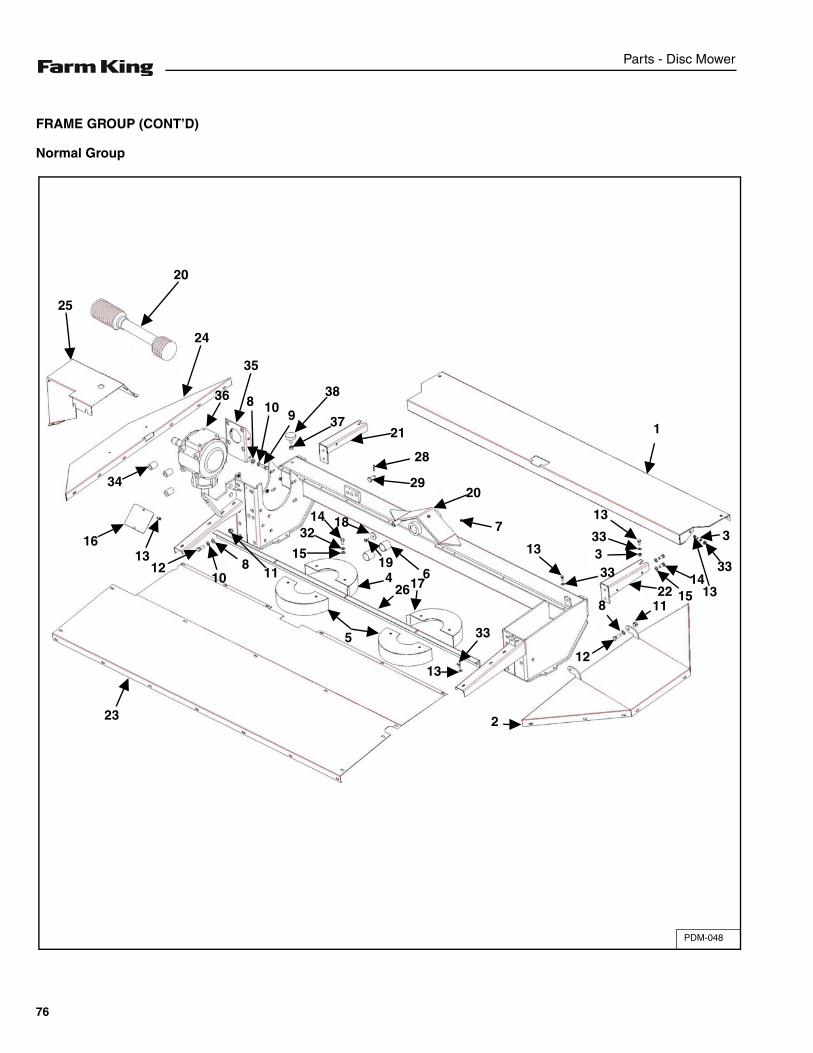
Parts - Disc Mower
FRAME GROUP (CONT’D)
Normal Group
PDM-048
34
36
35
24
20
25
1613
1210
811
15
3214 18
1964
2617
5
13
23
33
2
12
8
33
13
7
333
13
2029
28
1122 15
1413
33
3
1
8 109
38
3721
76
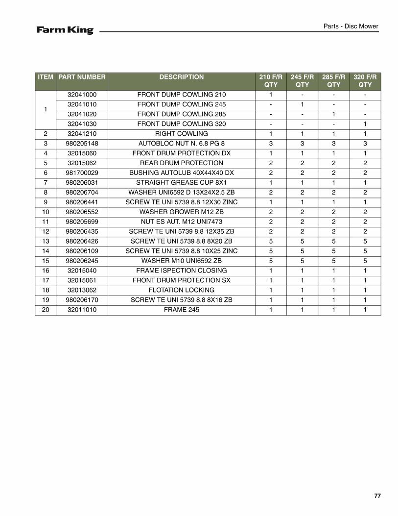
Parts - Disc Mower
ITEM PART NUMBER DESCRIPTION 210 F/R QTY
245 F/R QTY
285 F/R QTY
320 F/R QTY
1
32041000 FRONT DUMP COWLING 210 1 - - -
32041010 FRONT DUMP COWLING 245 - 1 - -
32041020 FRONT DUMP COWLING 285 - - 1 -
32041030 FRONT DUMP COWLING 320 - - - 1
2 32041210 RIGHT COWLING 1 1 1 1
3 980205148 AUTOBLOC NUT N. 6.8 PG 8 3 3 3 3
4 32015060 FRONT DRUM PROTECTION DX 1 1 1 1
5 32015062 REAR DRUM PROTECTION 2 2 2 2
6 981700029 BUSHING AUTOLUB 40X44X40 DX 2 2 2 2
7 980206031 STRAIGHT GREASE CUP 8X1 1 1 1 1
8 980206704 WASHER UNI6592 D 13X24X2.5 ZB 2 2 2 2
9 980206441 SCREW TE UNI 5739 8.8 12X30 ZINC 1 1 1 1
10 980206552 WASHER GROWER M12 ZB 2 2 2 2
11 980205699 NUT ES AUT. M12 UNI7473 2 2 2 2
12 980206435 SCREW TE UNI 5739 8.8 12X35 ZB 2 2 2 2
13 980206426 SCREW TE UNI 5739 8.8 8X20 ZB 5 5 5 5
14 980206109 SCREW TE UNI 5739 8.8 10X25 ZINC 5 5 5 5
15 980206245 WASHER M10 UNI6592 ZB 5 5 5 5
16 32015040 FRAME ISPECTION CLOSING 1 1 1 1
17 32015061 FRONT DRUM PROTECTION SX 1 1 1 1
18 32013062 FLOTATION LOCKING 1 1 1 1
19 980206170 SCREW TE UNI 5739 8.8 8X16 ZB 1 1 1 1
20 32011010 FRAME 245 1 1 1 1
77
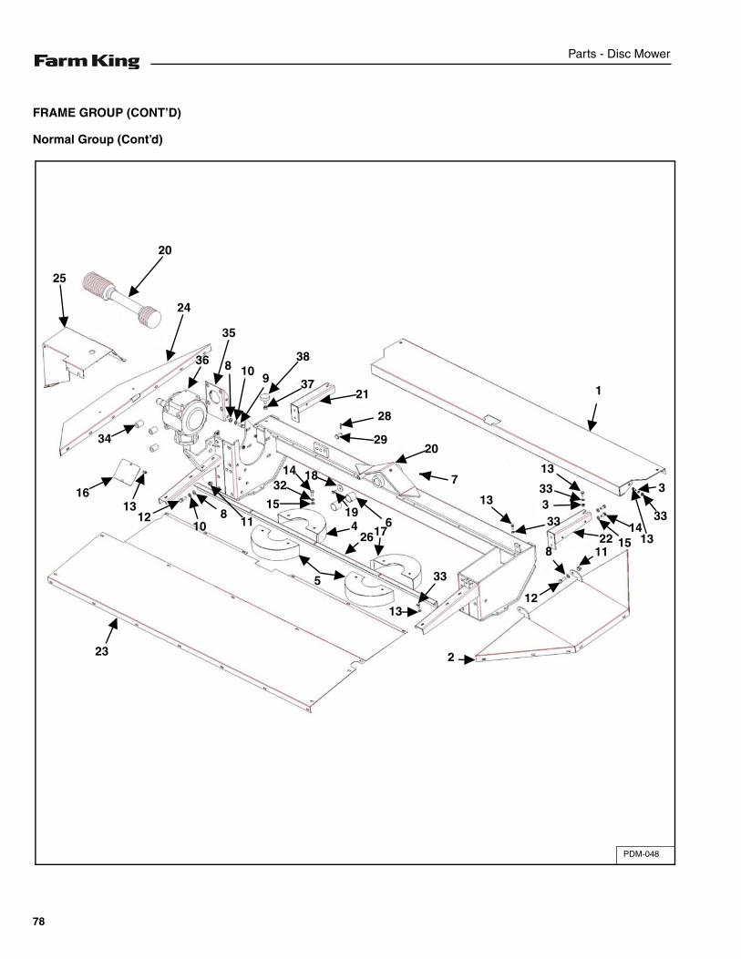
Parts - Disc Mower
FRAME GROUP (CONT’D)
Normal Group (Cont’d)
PDM-048
34
36
35
24
20
25
1613
1210
811
15
3214 18
1964
2617
5
13
23
33
2
12
8
33
13
7
333
13
2029
28
1122 15
1413
33
3
1
8 109
38
3721
78
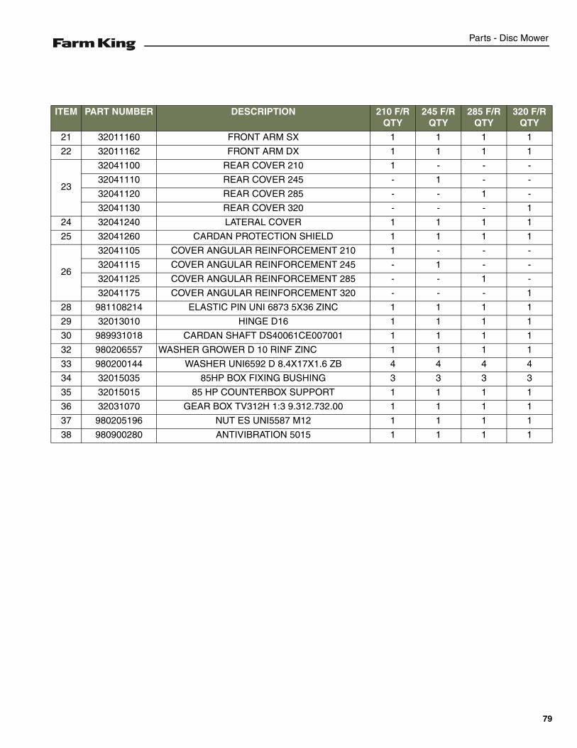
Parts - Disc Mower
ITEM PART NUMBER DESCRIPTION 210 F/R QTY
245 F/R QTY
285 F/R QTY
320 F/R QTY
21 32011160 FRONT ARM SX 1 1 1 1
22 32011162 FRONT ARM DX 1 1 1 1
23
32041100 REAR COVER 210 1 - - -
32041110 REAR COVER 245 - 1 - -
32041120 REAR COVER 285 - - 1 -
32041130 REAR COVER 320 - - - 1
24 32041240 LATERAL COVER 1 1 1 1
25 32041260 CARDAN PROTECTION SHIELD 1 1 1 1
26
32041105 COVER ANGULAR REINFORCEMENT 210 1 - - -
32041115 COVER ANGULAR REINFORCEMENT 245 - 1 - -
32041125 COVER ANGULAR REINFORCEMENT 285 - - 1 -
32041175 COVER ANGULAR REINFORCEMENT 320 - - - 1
28 981108214 ELASTIC PIN UNI 6873 5X36 ZINC 1 1 1 1
29 32013010 HINGE D16 1 1 1 1
30 989931018 CARDAN SHAFT DS40061CE007001 1 1 1 1
32 980206557 WASHER GROWER D 10 RINF ZINC 1 1 1 1
33 980200144 WASHER UNI6592 D 8.4X17X1.6 ZB 4 4 4 4
34 32015035 85HP BOX FIXING BUSHING 3 3 3 3
35 32015015 85 HP COUNTERBOX SUPPORT 1 1 1 1
36 32031070 GEAR BOX TV312H 1:3 9.312.732.00 1 1 1 1
37 980205196 NUT ES UNI5587 M12 1 1 1 1
38 980900280 ANTIVIBRATION 5015 1 1 1 1
79
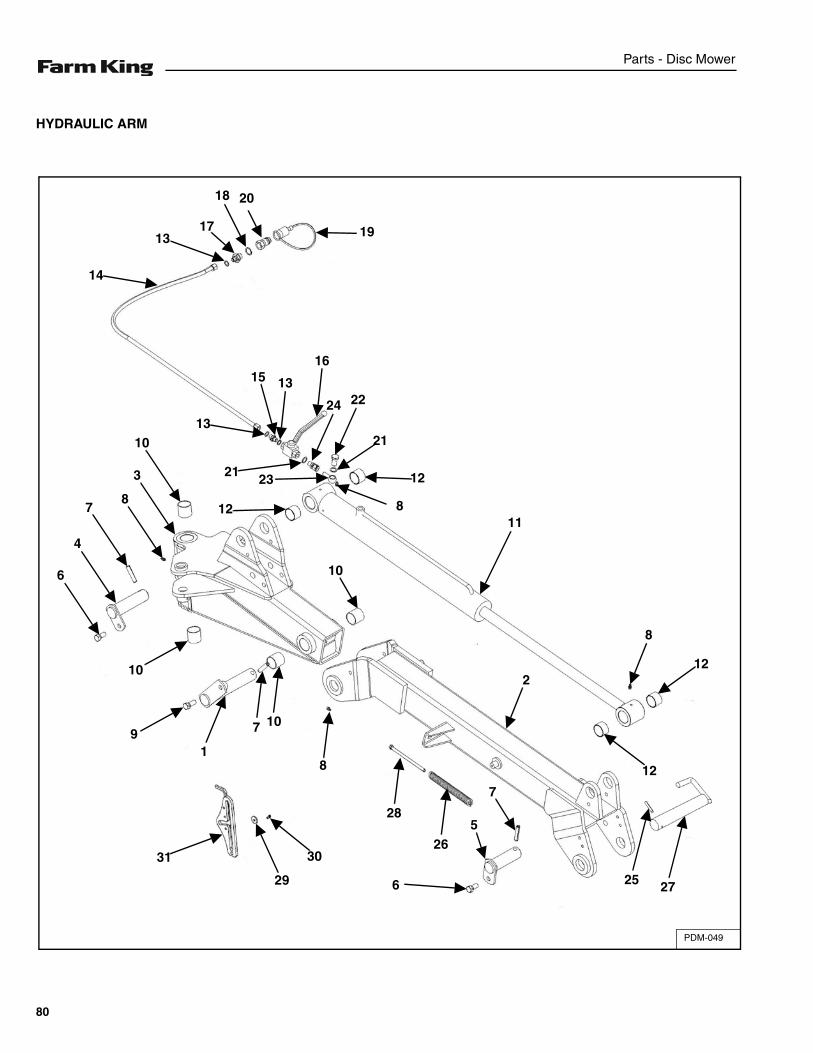
Parts - Disc Mower
HYDRAULIC ARM
PDM-049
19
2018
1713
14
15 13
16
24 22
21
21
13
23 12
12
10
3
87
4
6
10
91
7 10
8
28
30
29
3126
6
5
7
25 27
12
212
8
11
10
8
80
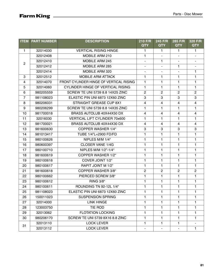
Parts - Disc Mower
ITEM PART NUMBER DESCRIPTION 210 F/R QTY
245 F/R QTY
285 F/R QTY
320 F/R QTY
1 32014030 VERTICAL RISING HINGE 1 1 1 1
2
32012408 MOBILE ARM 210 1 - - -
32012410 MOBILE ARM 245 - 1 - -
32012412 MOBILE ARM 285 - - 1 -
32012414 MOBILE ARM 320 - - - 1
3 32012512 MOBILE ARM ATTACK 1 1 1 1
4 32014070 FRONT CYLINDER HINGE OF VERTICAL RISING 1 1 1 1
5 32014060 CYLINDER HINGE OF VERTICAL RISING 1 1 1 1
6 980205559 SCREW TE UNI 5739 8.8 14X25 ZINC 2 2 2 2
7 981108023 ELASTIC PIN UNI 6873 12X60 ZINC 3 3 3 3
8 980206031 STRAIGHT GREASE CUP 8X1 4 4 4 4
9 980206299 SCREW TE UNI 5739 8.8 14X35 ZINC 1 1 1 1
10 981700018 BRASS AUTOLUB 40X44X50 DX 4 4 4 4
11 32016030 VERTICAL LIFT CYLINDER 70x600 1 1 1 1
12 981700021 BRASS AUTOLUB 40X44X30 DX 4 4 4 4
13 981600630 COPPER WASHER 1/4“ 3 3 3 3
14 981013417 TUBE 1/4”L=2900 FD/FD 1 1 1 1
15 980100626 NIPLES M/M 1/4“ 1 1 1 1
16 980600397 CLOSER VANE 1/4G 1 1 1 1
17 980100710 NIPLES M/M 1/2”-1/4“ 1 1 1 1
18 981600619 COPPER WASHER 1/2“ 1 1 1 1
19 980100618 COVER JOINT 1/2“ 1 1 1 1
20 980100617 RAPIT JOINT M 1/2“ 1 1 1 1
21 981600618 COPPER WASHER 3/8“ 2 2 2 2
22 980100662 PIERCED SCREW 3/8“ 1 1 1 1
23 980100612 RING 3/8“ 1 1 1 1
24 980100611 ROUNDING TN 92-12L 1/4“ 1 1 1 1
25 981108023 ELASTIC PIN UNI 6873 12X60 ZINC 1 1 1 1
26 150011023 SUSPENSION SPRING 1 1 1 1
27 32014000 LINK HINGE 1 1 1 1
28 123003750 TIE ROD 1 1 1 1
29 32013062 FLOTATION LOCKING 1 1 1 1
30 980206170 SCREW TE UNI 5739 8X16 8.8 ZINC 1 1 1 1
3132013110 LOCK LEVER 1 1 1 -
32013112 LOCK LEVER - - - 1
81

Parts - Disc Mower
CUTTER BAR
PDM-050
5224
23
333
11
13
12
4
149
106
6
16
15 10
7
8
20
35
6
2
5
1
20
19
55
46 2615
58
56
657
5349
37
34
30
3832
37
30
3332
31 3136
41
4046
47
45
51
44
43
6
42
50
4948
39
17
18 24
2322
48
5647
59
27
61
621
28
29
82
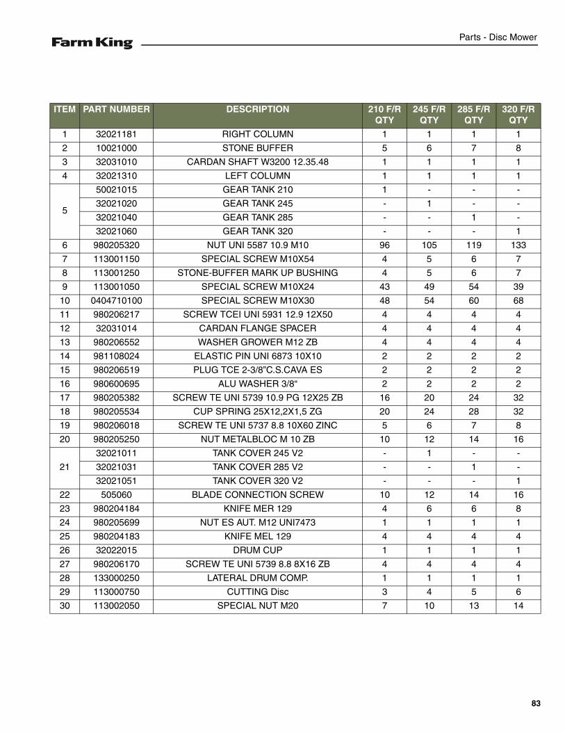
Parts - Disc Mower
ITEM PART NUMBER DESCRIPTION 210 F/R QTY
245 F/R QTY
285 F/R QTY
320 F/R QTY
1 32021181 RIGHT COLUMN 1 1 1 1
2 10021000 STONE BUFFER 5 6 7 8
3 32031010 CARDAN SHAFT W3200 12.35.48 1 1 1 1
4 32021310 LEFT COLUMN 1 1 1 1
5
50021015 GEAR TANK 210 1 - - -
32021020 GEAR TANK 245 - 1 - -
32021040 GEAR TANK 285 - - 1 -
32021060 GEAR TANK 320 - - - 1
6 980205320 NUT UNI 5587 10.9 M10 96 105 119 133
7 113001150 SPECIAL SCREW M10X54 4 5 6 7
8 113001250 STONE-BUFFER MARK UP BUSHING 4 5 6 7
9 113001050 SPECIAL SCREW M10X24 43 49 54 39
10 0404710100 SPECIAL SCREW M10X30 48 54 60 68
11 980206217 SCREW TCEI UNI 5931 12.9 12X50 4 4 4 4
12 32031014 CARDAN FLANGE SPACER 4 4 4 4
13 980206552 WASHER GROWER M12 ZB 4 4 4 4
14 981108024 ELASTIC PIN UNI 6873 10X10 2 2 2 2
15 980206519 PLUG TCE 2-3/8”C.S.CAVA ES 2 2 2 2
16 980600695 ALU WASHER 3/8“ 2 2 2 2
17 980205382 SCREW TE UNI 5739 10.9 PG 12X25 ZB 16 20 24 32
18 980205534 CUP SPRING 25X12,2X1,5 ZG 20 24 28 32
19 980206018 SCREW TE UNI 5737 8.8 10X60 ZINC 5 6 7 8
20 980205250 NUT METALBLOC M 10 ZB 10 12 14 16
21
32021011 TANK COVER 245 V2 - 1 - -
32021031 TANK COVER 285 V2 - - 1 -
32021051 TANK COVER 320 V2 - - - 1
22 505060 BLADE CONNECTION SCREW 10 12 14 16
23 980204184 KNIFE MER 129 4 6 6 8
24 980205699 NUT ES AUT. M12 UNI7473 1 1 1 1
25 980204183 KNIFE MEL 129 4 4 4 4
26 32022015 DRUM CUP 1 1 1 1
27 980206170 SCREW TE UNI 5739 8.8 8X16 ZB 4 4 4 4
28 133000250 LATERAL DRUM COMP. 1 1 1 1
29 113000750 CUTTING Disc 3 4 5 6
30 113002050 SPECIAL NUT M20 7 10 13 14
83
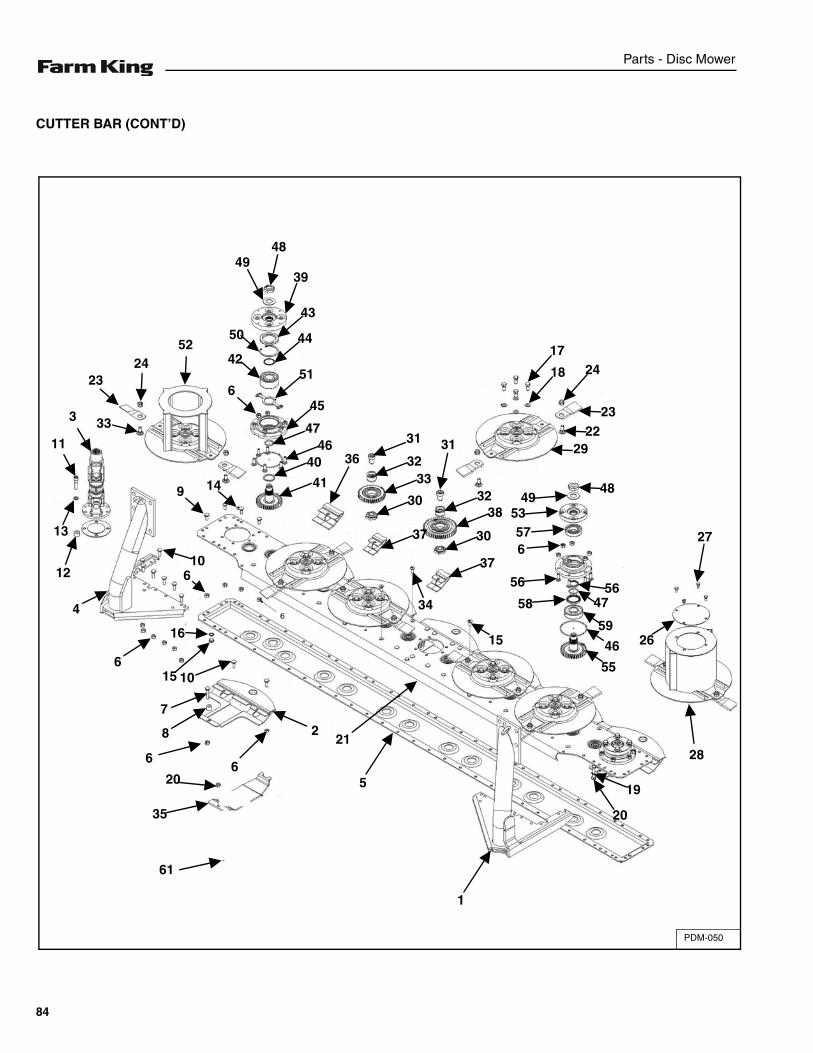
Parts - Disc Mower
CUTTER BAR (CONT’D)
PDM-050
5224
23
333
11
13
12
4
149
106
6
16
15 10
7
8
20
35
6
2
5
1
20
19
55
46 2615
58
56
657
5349
37
34
30
3832
37
30
3332
31 3136
41
4046
47
45
51
44
43
6
42
50
4948
39
17
18 24
2322
48
5647
59
27
61
621
28
29
84
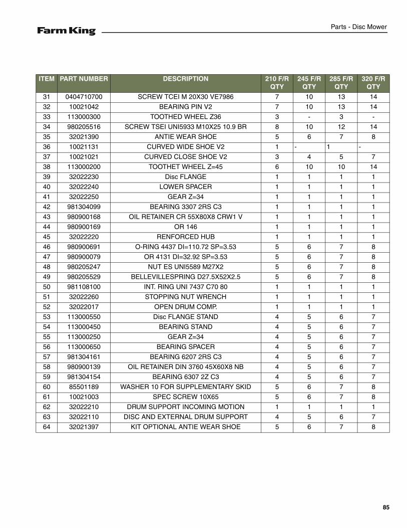
Parts - Disc Mower
ITEM PART NUMBER DESCRIPTION 210 F/R QTY
245 F/R QTY
285 F/R QTY
320 F/R QTY
31 0404710700 SCREW TCEI M 20X30 VE7986 7 10 13 14
32 10021042 BEARING PIN V2 7 10 13 14
33 113000300 TOOTHED WHEEL Z36 3 - 3 -
34 980205516 SCREW TSEI UNI5933 M10X25 10.9 BR 8 10 12 14
35 32021390 ANTIE WEAR SHOE 5 6 7 8
36 10021131 CURVED WIDE SHOE V2 1 - 1 -
37 10021021 CURVED CLOSE SHOE V2 3 4 5 7
38 113000200 TOOTHET WHEEL Z=45 6 10 10 14
39 32022230 Disc FLANGE 1 1 1 1
40 32022240 LOWER SPACER 1 1 1 1
41 32022250 GEAR Z=34 1 1 1 1
42 981304099 BEARING 3307 2RS C3 1 1 1 1
43 980900168 OIL RETAINER CR 55X80X8 CRW1 V 1 1 1 1
44 980900169 OR 146 1 1 1 1
45 32022220 RENFORCED HUB 1 1 1 1
46 980900691 O-RING 4437 DI=110.72 SP=3.53 5 6 7 8
47 980900079 OR 4131 DI=32.92 SP=3.53 5 6 7 8
48 980205247 NUT ES UNI5589 M27X2 5 6 7 8
49 980205529 BELLEVILLESPRING D27.5X52X2.5 5 6 7 8
50 981108100 INT. RING UNI 7437 C70 80 1 1 1 1
51 32022260 STOPPING NUT WRENCH 1 1 1 1
52 32022017 OPEN DRUM COMP. 1 1 1 1
53 113000550 Disc FLANGE STAND 4 5 6 7
54 113000450 BEARING STAND 4 5 6 7
55 113000250 GEAR Z=34 4 5 6 7
56 113000650 BEARING SPACER 4 5 6 7
57 981304161 BEARING 6207 2RS C3 4 5 6 7
58 980900139 OIL RETAINER DIN 3760 45X60X8 NB 4 5 6 7
59 981304154 BEARING 6307 2Z C3 4 5 6 7
60 85501189 WASHER 10 FOR SUPPLEMENTARY SKID 5 6 7 8
61 10021003 SPEC SCREW 10X65 5 6 7 8
62 32022210 DRUM SUPPORT INCOMING MOTION 1 1 1 1
63 32022110 DISC AND EXTERNAL DRUM SUPPORT 4 5 6 7
64 32021397 KIT OPTIONAL ANTIE WEAR SHOE 5 6 7 8
85
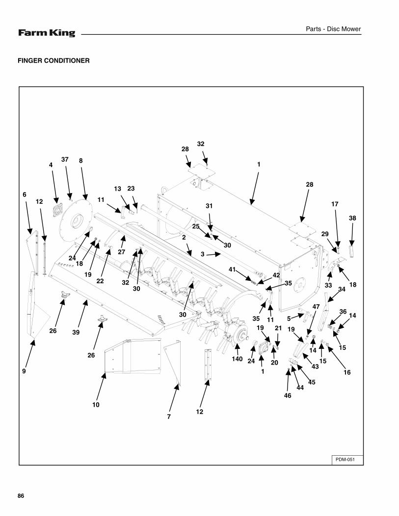
Parts - Disc Mower
FINGER CONDITIONER
PDM-051
2832
1
28
29
17
38
183334
36145
3542
41
330
31
2
25
2313
11
8374
126
2418
1922
27
3230
3035 11
19 21 19
47
14
16
15
1543
4544
46
201
24140
127
10
26
3926
9
86
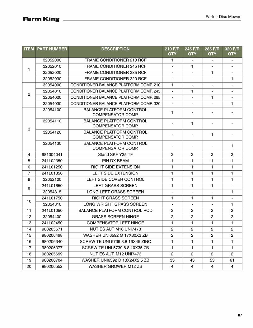
Parts - Disc Mower
ITEM PART NUMBER DESCRIPTION 210 F/R QTY
245 F/R QTY
285 F/R QTY
320 F/R QTY
1
32052000 FRAME CONDITIONER 210 RCF 1 - - -
32052010 FRAME CONDITIONER 245 RCF - 1 - -
32052020 FRAME CONDITIONER 285 RCF - - 1 -
32052030 FRAME CONDITIONER 320 RCF - - - 1
2
32054000 CONDITIONER BALANCE PLATFORM COMP. 210 1 - - -
32054010 CONDITIONER BALANCE PLATFORM COMP. 245 - 1 - -
32054020 CONDITIONER BALANCE PLATFORM COMP. 285 - - 1 -
32054030 CONDITIONER BALANCE PLATFORM COMP. 320 - - - 1
3
32054100 BALANCE PLATFORM CONTROL COMPENSATOR COMP.
1 - - -
32054110 BALANCE PLATFORM CONTROL COMPENSATOR COMP.
- 1 - -
32054120 BALANCE PLATFORM CONTROL COMPENSATOR COMP.
- - 1 -
32054130 BALANCE PLATFORM CONTROL COMPENSATOR COMP.
- - - 1
4 981304041 Stand SKF Y35 TF 2 2 2 2
5 241L02350 PIN DX BEAM 1 1 1 1
6 241L01250 RIGHT SIDE EXTENSION 1 1 1 1
7 241L01350 LEFT SIDE EXTENSION 1 1 1 1
8 32052100 LEFT SIDE COVER CONTROL 1 1 1 1
9241L01650 LEFT GRASS SCREEN 1 1 1 -
32054315 LONG LEFT GRASS SCREEN - - - 1
10241L01750 RIGHT GRASS SCREEN 1 1 1 -
32054310 LONG WRIGHT GRASS SCREEN - - - 1
11 241L01050 BALANCE PLATFORM CONTROL ROD 2 2 2 2
12 32054400 GRASS SCREEN HINGE 2 2 2 2
13 241L02450 COMPENSATOR LEFT HINGE 1 1 1 1
14 980205671 NUT ES AUT M16 UNI7473 2 2 2 2
15 980206498 WASHER UNI6592 Ø 17X30X3 ZB 2 2 2 2
16 980206340 SCREW TE UNI 5739 8.8 16X45 ZINC 1 1 1 1
17 980206377 SCREW TE UNI 5739 8.8 10X35 ZB 1 1 1 1
18 980205699 NUT ES AUT. M12 UNI7473 2 2 2 2
19 980206704 WASHER UNI6592 D 13X24X2.5 ZB 33 43 53 61
20 980206552 WASHER GROWER M12 ZB 4 4 4 4
87
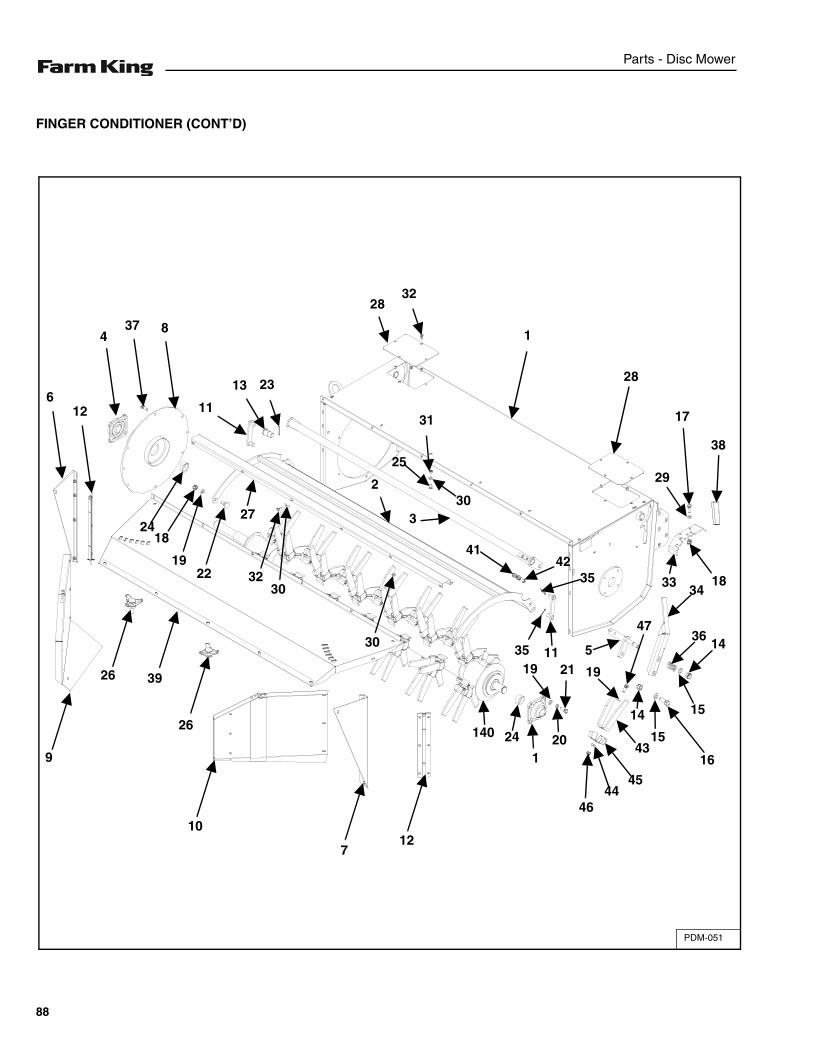
Parts - Disc Mower
FINGER CONDITIONER (CONT’D)
PDM-051
2832
1
28
29
17
38
183334
36145
3542
41
330
31
2
25
2313
11
8374
126
2418
1922
27
3230
3035 11
19 21 19
47
14
16
15
1543
4544
46
201
24140
127
10
26
3926
9
88
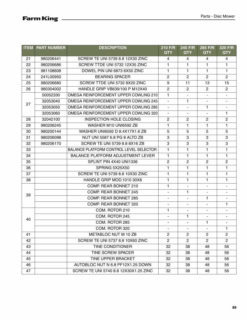
Parts - Disc Mower
ITEM PART NUMBER DESCRIPTION 210 F/R QTY
245 F/R QTY
285 F/R QTY
320 F/R QTY
21 980206441 SCREW TE UNI 5739 8.8 12X30 ZINC 4 4 4 4
22 980206686 SCREW TTDE UNI 5732 12X35 ZINC 1 1 1 1
23 981108608 DOWEL PIN UNI 6873 6X50 ZINC 1 1 1 1
24 241L00950 BEARING SPACER 2 2 2 2
25 980206680 SCREW TTDE UNI 5732 8X20 ZINC 9 11 13 15
26 980304002 HANDLE GRIP VB639/100 P M12X40 2 2 2 2
27
50052330 OMEGA REINFORCEMENT UPPER COWLING 210 1 - - -
32053040 OMEGA REINFORCEMENT UPPER COWLING 245 - 1 - -
32053050 OMEGA REINFORCEMENT UPPER COWLING 285 - - 1 -
32053060 OMEGA REINFORCEMENT UPPER COWLING 320 - - - 1
28 32042100 INSPECTION HOLE CLOSING 2 2 2 2
29 980206245 WASHER M10 UNI6592 ZB 1 1 1 1
30 980200144 WASHER UNI6592 D 8.4X17X1.6 ZB 5 5 5 5
31 980206098 NUT UNI 5587 6.8 PG 8 ALTO ZB 3 3 3 3
32 980206170 SCREW TE UNI 5739 8.8 8X16 ZB 3 3 3 3
33 BALANCE PLATFORM CONTROL LEVEL SELECTOR 1 1 1 1
34 BALANCE PLATFORM ADJUSTMENT LEVER 1 1 1 1
35 SPLINT PIN 4X40 UNI1336 2 2 2 2
36 SPRING 5X25X50 1 1 1 1
37 SCREW TE UNI 5739 8.8 10X30 ZINC 1 1 1 1
38 HANDLE GRIP MOD.1010 30X8 1 1 1 1
39
COMP. REAR BONNET 210 1 - - -
COMP. REAR BONNET 245 - 1 - -
COMP. REAR BONNET 285 - - 1 -
COMP. REAR BONNET 320 - - - 1
40
COM. ROTOR 210 1 - - -
COM. ROTOR 245 - 1 - -
COM. ROTOR 285 - - 1 -
COM. ROTOR 320 - - - 1
41 METABLOC NUT M 10 ZB 2 2 2 2
42 SCREW TE UNI 5737 8.8 10X60 ZINC 2 2 2 2
43 TINE CONDITIONER 32 38 48 56
44 TINE SCREW SPACER 32 38 48 56
45 TINE UPPER BRACKET 32 38 48 56
46 AUTOBLOC NUT N 6.8 PF12X1.25 DOWN 32 38 48 56
47 SCREW TE UNI 5740 8.8 12X30X1.25 ZINC 32 38 48 56
89

Parts - Disc Mower
ROLLER CONDITIONER
PDM-052
28
30
16
17
11
3132 33
33
34
1458
4
52
16
1718
5150
1 4038 35
38
14
3637
51
2037
14
10
41
42
241
20
25
43
44
2524
771
2322
68
67
6822
4645
47
49
2422
2928
545655
12181716
4
58
4 40
16
1
30
19
60 21 171821 176
131
66
6162
7674
33
57
13
20
27 29
195 14
24
23
6475
63
2226
25
9
19
90
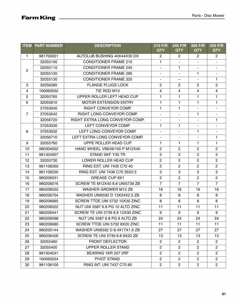
Parts - Disc Mower
ITEM PART NUMBER DESCRIPTION 210 F/R QTY
245 F/R QTY
285 F/R QTY
320 F/R QTY
1 981700021 AUTOLUB BUSHING 40X44X30 DX 2 2 2 2
2
32055100 CONDITIONER FRAME 210 1 - - -
32055110 CONDITIONER FRAME 245 - 1 - -
32055120 CONDITIONER FRAME 285 - - 1 -
32055130 CONDITIONER FRAME 320 - -- - 1
3 32056280 FLANGE PLUGS LOCK 2 2 2 2
4 160060032 TIE ROD M10 4 4 4 4
5 32055765 UPPER ROLLER LEFT HEAD CUP 1 1 1 1
6 32055810 MOTOR EXTENSION ENTRY 1 1 1 1
7
37053040 RIGHT CONVEYOR COMP. 1 1 - -
37053042 RIGHT LONG CONVEYOR COMP. - - 1 -
32056720 RIGHT EXTRA LONG CONVEYOR COMP. - - - 1
8
37053030 LEFT CONVEYOR COMP. 1 1 - -
37053032 LEFT LONG CONVEYOR COMP. - - 1 -
32056710 LEFT EXTRA LONG CONVEYOR COMP. - - - 1
9 32055760 UPPE ROLLER HEAD CUP 1 1 1 1
10 980304002 HAND WHEEL VB639/100 P M12X40 2 2 2 2
11 981304007 STAND SKF Y35 TR 2 2 2 2
12 32055730 LOWER ROLLER HEAD CUP 2 2 2 2
13 981108260 RING EST. UNI 7435 C70 40 2 2 2 2
14 981108250 RING EST. UNI 7436 C70 35X2.5 3 3 3 3
15 980206031 GREASE CUP 8X1 2 2 2 2
16 980206016 SCREW TE M12X40 8.8 UNI5739 ZB 7 7 7 7
17 980206552 WASHER GROWER M12 ZB 16 16 16 16
18 980206704 WASHER UNI6592 D 13X24X2.5 ZB 8 8 8 8
19 980206685 SCREW TTDE UNI 5732 10X30 ZINC 8 8 8 8
20 980206022 NUT UNI 5587 6.8 PG 10 ALTO ZINC 11 11 11 11
21 980206441 SCREW TE UNI 5739 8.8 12X30 ZINC 9 9 9 9
22 980206098 NUT UNI 5587 6.8 PG 8 ALTO ZB 24 24 24 24
23 980206680 SCREW TTDE UNI 5732 8X20 ZINC 11 11 11 11
24 980200144 WASHER UNI6592 D 8.4X17X1.6 ZB 27 27 27 27
25 980206426 SCREW TE UNI 5739 8.8 8X20 ZB 13 13 13 13
26 32055460 FRONT DEFLECTOR 2 2 2 2
27 32055400 UPPER ROLLER STAND 2 2 2 2
28 981304031 BEARING YAR 207 2RF 2 2 2 2
29 160060024 PIVOT STAND. 2 2 2 2
30 981108100 RING INT. UNI 7437 C70 80 2 2 2 2
91
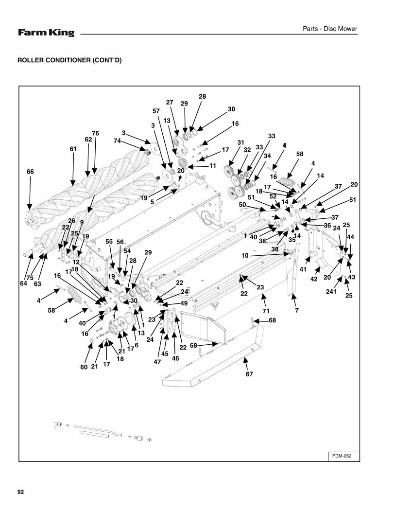
Parts - Disc Mower
ROLLER CONDITIONER (CONT’D)
PDM-052
28
30
16
17
11
3132 33
33
34
1458
4
52
16
1718
5150
1 4038 35
38
14
3637
51
2037
14
10
41
42
241
20
25
43
44
2524
771
2322
68
67
6822
4645
47
49
2422
2928
545655
12181716
4
58
4 40
16
1
30
19
60 21 171821 176
131
66
6162
7674
33
57
13
20
27 29
195 14
24
23
6475
63
2226
25
9
19
92

Parts - Disc Mower
ITEM PART NUMBER DESCRIPTION 210 F/R QTY
245 F/R QTY
285 F/R QTY
320 F/R QTY
31 32056610 TORQUE TOOTHED WHEEL Z=25 2 2 2 2
32 32056620 TOOTHED WHEEL 2 2 2 2
33 981304162 BEARING 6206 2RS C3 4 4 4 4
34 981108051 RING INT. UNI 7437 C70 62 2 2 2 2
35 150030010 SPACER 35 X 5 2 2 2 2
36 32056630 TOOTHED WHEEL JOINT 1 1 1 1
37 981108247 RING EST. UNI 7436 C70 30X2 2 2 2 2
38 980200736 RING DIN 988 30x40X1 4 4 4 4
39
32055500 MOBILE PIN JOINT 210 1 - - -
32055510 MOBILE PIN JOINT 245 - 1 - -
32055512 MOBILE PIN JOINT 285 - - 1 -
32055514 MOBILE PIN JOINT 320 - - - 1
40 32055560 SPRING PIN TIE ROD 2 2 2 2
41 32042135 FRONT COVER COMP. 1 1 1 1
42 32042140 LATERAL SHIELD COVER 1 1 1 1
43 32056650 EYE SCREW FOR LUBRIFICATION 1 1 1 1
44 980206128 STRAIGHT GREASE CUP 6X1 1 1 1 1
45 32055570 EXTERNAL CONVEYOR HINGE 2 2 2 2
46 32055580 INNER CONVEYOR HINGE 2 2 2 2
47 32055590 HINGE PIN COMP 2 2 2 2
48 980206030 SPLIT PIN 2 2 2 2
49 980206437 SCREW TE UNI 5739 8.8 8X25 ZINC 8 8 8 8
50 32055015 UPPER ROLLER GREASE SOCKET 2 2 2 2
93

Parts - Disc Mower
ROLLER CONDITIONER (CONT’D)
PDM-052
28
30
16
17
11
3132 33
33
34
1458
4
52
16
1718
5150
1 4038 35
38
14
3637
51
2037
14
10
41
42
241
20
25
43
44
2524
771
2322
68
67
6822
4645
47
49
2422
2928
545655
12181716
4
58
4 40
16
1
30
19
60 21 171821 176
131
66
6162
7674
33
57
13
20
27 29
195 14
24
23
6475
63
2226
25
9
19
94
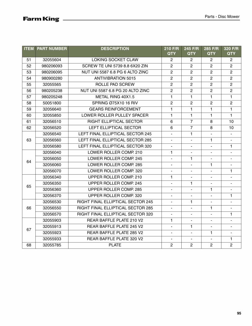
Parts - Disc Mower
ITEM PART NUMBER DESCRIPTION 210 F/R QTY
245 F/R QTY
285 F/R QTY
320 F/R QTY
51 32055604 LOKING SOCKET CLAW 2 2 2 2
52 980206093 SCREW TE UNI 5739 8.8 6X20 ZIN 2 2 2 2
53 980206095 NUT UNI 5587 6.8 PG 6 ALTO ZINC 2 2 2 2
54 980900280 ANTIVIBRATION 5015 2 2 2 2
55 32055565 ROLLE PAD SCREW 2 2 2 2
56 980205238 NUT UNI 5587 6.8 PG 20 ALTO ZINC 2 2 2 2
57 980205248 METAL RING 40X1.5 1 1 1 1
58 50051800 SPRING Ø75X10 16 RIV 2 2 2 2
59 32056640 GEARS REINFORCEMENT 1 1 1 1
60 32055850 LOWER ROLLER PULLEY SPACER 1 1 1 1
61 32056510 RIGHT ELLIPTICAL SECTOR 6 7 8 10
62 32056520 LEFT ELLIPTICAL SECTOR 6 7 8 10
63
32056540 LEFT FINAL ELLIPTICAL SECTOR 245 - 1 - -
32056560 LEFT FINAL ELLIPTICAL SECTOR 285 - - 1 -
32056580 LEFT FINAL ELLIPTICAL SECTOR 320 - - - 1
64
32056040 LOWER ROLLER COMP. 210 1 - - -
32056050 LOWER ROLLER COMP. 245 - 1 - -
32056060 LOWER ROLLER COMP. 285 - - 1 -
32056070 LOWER ROLLER COMP. 320 - - - 1
65
32056340 UPPER ROLLER COMP. 210 1 - - -
32056350 UPPER ROLLER COMP. 245 - 1 - -
32056360 UPPER ROLLER COMP. 285 - - 1 -
32056370 UPPER ROLLER COMP. 320 - - - 1
66
32056530 RIGHT FINAL ELLIPTICAL SECTOR 245 - 1 - -
32056550 RIGHT FINAL ELLIPTICAL SECTOR 285 - - 1 -
32056570 RIGHT FINAL ELLIPTICAL SECTOR 320 - - - 1
67
32055903 REAR BAFFLE PLATE 210 V2 1 - - -
32055913 REAR BAFFLE PLATE 245 V2 - 1 - -
32055923 REAR BAFFLE PLATE 285 V2 - - 1 -
32055933 REAR BAFFLE PLATE 320 V2 - - - 1
68 32055785 PLATE 2 2 2 2
95
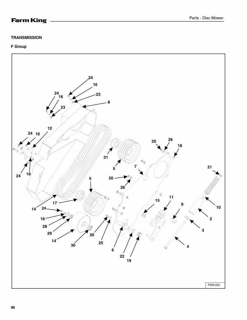
Parts - Disc Mower
TRANSMISSION
F Group
PDM-053
24
16
232416
23
20 26
18
31
5
5 20
26
7 21
915
11
10
2
3
4
1922
6
25
20
3014
29
28
16
2417
14
24 16
121624
8
96
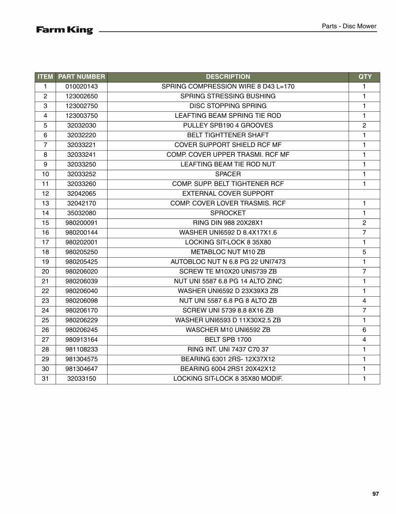
Parts - Disc Mower
ITEM PART NUMBER DESCRIPTION QTY
1 010020143 SPRING COMPRESSION WIRE 8 D43 L=170 1
2 123002650 SPRING STRESSING BUSHING 1
3 123002750 DISC STOPPING SPRING 1
4 123003750 LEAFTING BEAM SPRING TIE ROD 1
5 32032030 PULLEY SPB190 4 GROOVES 2
6 32032220 BELT TIGHTTENER SHAFT 1
7 32033221 COVER SUPPORT SHIELD RCF MF 1
8 32033241 COMP. COVER UPPER TRASMI. RCF MF 1
9 32033250 LEAFTING BEAM TIE ROD NUT 1
10 32033252 SPACER 1
11 32033260 COMP. SUPP. BELT TIGHTENER RCF 1
12 32042065 EXTERNAL COVER SUPPORT
13 32042170 COMP. COVER LOVER TRASMIS. RCF 1
14 35032080 SPROCKET 1
15 980200091 RING DIN 988 20X28X1 2
16 980200144 WASHER UNI6592 D 8.4X17X1.6 7
17 980202001 LOCKING SIT-LOCK 8 35X80 1
18 980205250 METABLOC NUT M10 ZB 5
19 980205425 AUTOBLOC NUT N 6.8 PG 22 UNI7473 1
20 980206020 SCREW TE M10X20 UNI5739 ZB 7
21 980206039 NUT UNI 5587 6.8 PG 14 ALTO ZINC 1
22 980206040 WASHER UNI6592 D 23X39X3 ZB 1
23 980206098 NUT UNI 5587 6.8 PG 8 ALTO ZB 4
24 980206170 SCREW UNI 5739 8.8 8X16 ZB 7
25 980206229 WASHER UNI6593 D 11X30X2.5 ZB 1
26 980206245 WASCHER M10 UNI6592 ZB 6
27 980913164 BELT SPB 1700 4
28 981108233 RING INT. UNI 7437 C70 37 1
29 981304575 BEARING 6301 2RS- 12X37X12 1
30 981304647 BEARING 6004 2RS1 20X42X12 1
31 32033150 LOCKING SIT-LOCK 8 35X80 MODIF. 1
97
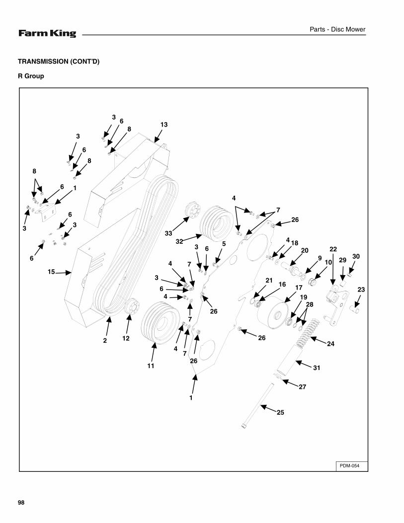
Parts - Disc Mower
TRANSMISSION (CONT’D)
R Group
PDM-054
4
138
63
8
6
3
8
6 1
3
6
3
6
15
3332 5
63
74
3
64
726
2 12
11
47
26
1
25
27
31
2426
2116 17
1928
4 1820
910
22
29 30
23
267
98
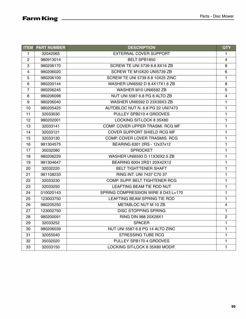
Parts - Disc Mower
ITEM PART NUMBER DESCRIPTION QTY
1 32042065 EXTERNAL COVER SUPPORT 1
2 980913014 BELT SPB1850 4
3 980206170 SCREW TE UNI 5739 8.8 8X16 ZB 8
4 980206020 SCREW TE M10X20 UNI5739 ZB 6
5 980206109 SCREW TE UNI 5739 8.8 10X25 ZINC 1
6 980200144 WASHER UNI6592 D 8.4X17X1.6 ZB 8
7 980206245 WASHER M10 UNI6592 ZB 5
8 980206098 NUT UNI 5587 6.8 PG 8 ALTO ZB 4
9 980206040 WASHER UNI6592 D 23X39X3 ZB 1
10 980205425 AUTOBLOC NUT N. 6.8 PG 22 UNI7473 1
11 32033030 PULLEY SPB210 4 GROOVES 1
12 980202001 LOCKING SIT-LOCK 8 35X80 1
13 32033141 COMP. COVER UPPER TRASMI. RCG MF 1
14 32033121 COVER SUPPORT SHIELD RCG MF 1
15 32033130 COMP. COVER LOVER TRASMIS. RCG 1
16 981304575 BEARING 6301 2RS - 12x37x12 1
17 35032080 SPROCKET 1
18 980206229 WASHER UNI6593 D 11X30X2.5 ZB 1
19 981304647 BEARING 6004 2RS1 20X42X12 1
20 32032220 BELT TIGHTTENER SHAFT 1
21 981108233 RING INT. UNI 7437 C70 37 1
22 32033230 COMP. SUPP. BELT TIGHTENER RCG 1
23 32033250 LEAFTING BEAM TIE ROD NUT 1
24 010020143 SPRING COMPRESSION WIRE 8 D43 L=170 1
25 123003750 LEAFTING BEAM SPRING TIE ROD 1
26 980205250 METABLOC NUT M 10 ZB 4
27 123002750 DISC STOPPING SPRING 1
28 980200091 RING DIN 988 20X28X1 2
29 32033252 SPACER 1
30 980206039 NUT UNI 5587 6.8 PG 14 ALTO ZINC 1
31 32055040 STRESSING TUBE RCG 1
32 35032020 PULLEY SPB170 4 GROOVES 1
33 32033150 LOCKING SIT-LOCK 8 35X80 MODIF. 1
99
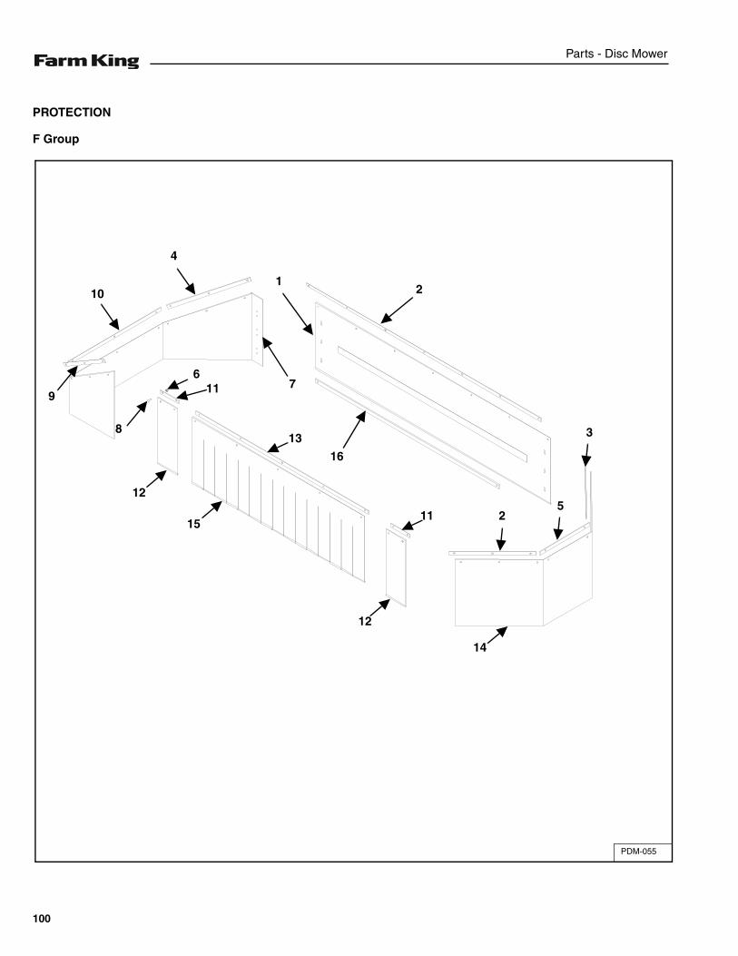
Parts - Disc Mower
PROTECTION
F Group
PDM-055
2
16
1
7
4
10
9
8
611
13
12
1511
12
14
25
3
100
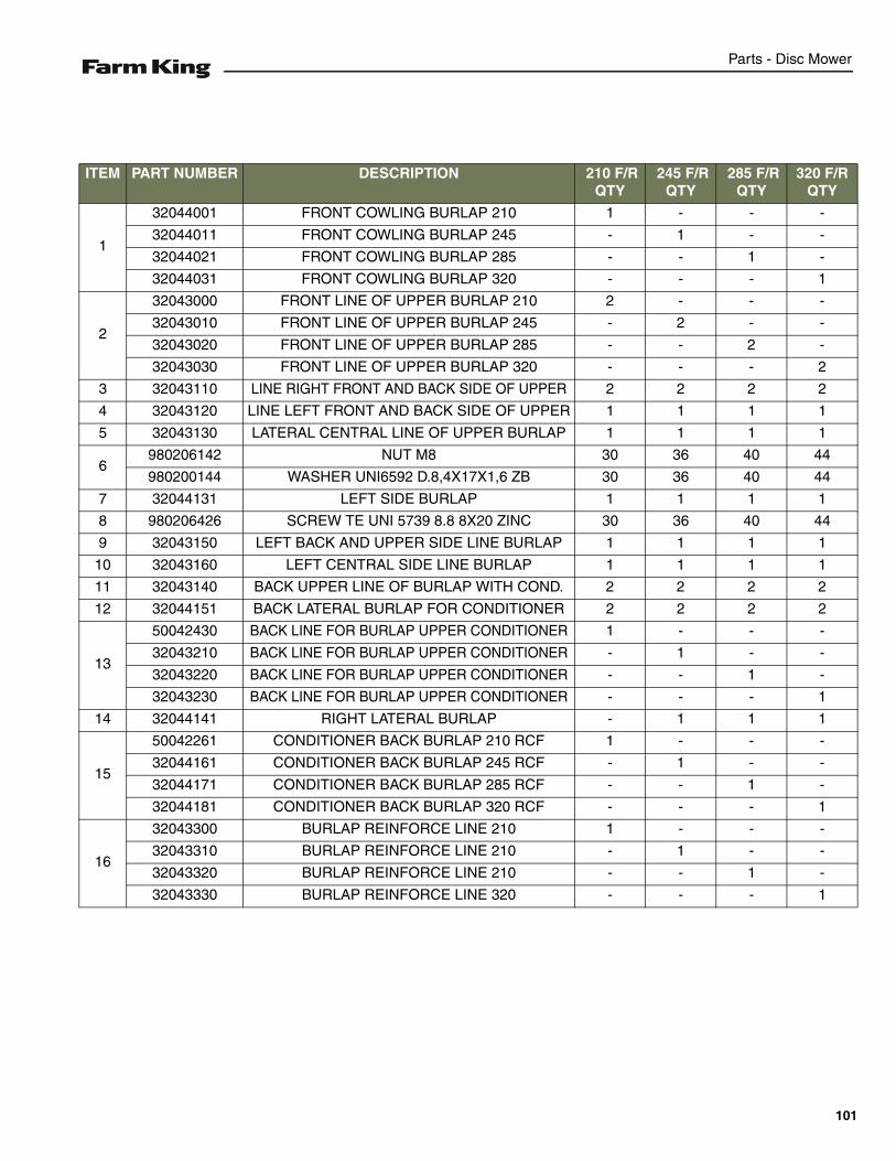
Parts - Disc Mower
ITEM PART NUMBER DESCRIPTION 210 F/R QTY
245 F/R QTY
285 F/R QTY
320 F/R QTY
1
32044001 FRONT COWLING BURLAP 210 1 - - -
32044011 FRONT COWLING BURLAP 245 - 1 - -
32044021 FRONT COWLING BURLAP 285 - - 1 -
32044031 FRONT COWLING BURLAP 320 - - - 1
2
32043000 FRONT LINE OF UPPER BURLAP 210 2 - - -
32043010 FRONT LINE OF UPPER BURLAP 245 - 2 - -
32043020 FRONT LINE OF UPPER BURLAP 285 - - 2 -
32043030 FRONT LINE OF UPPER BURLAP 320 - - - 2
3 32043110 LINE RIGHT FRONT AND BACK SIDE OF UPPER 2 2 2 2
4 32043120 LINE LEFT FRONT AND BACK SIDE OF UPPER 1 1 1 1
5 32043130 LATERAL CENTRAL LINE OF UPPER BURLAP 1 1 1 1
6980206142 NUT M8 30 36 40 44
980200144 WASHER UNI6592 D.8,4X17X1,6 ZB 30 36 40 44
7 32044131 LEFT SIDE BURLAP 1 1 1 1
8 980206426 SCREW TE UNI 5739 8.8 8X20 ZINC 30 36 40 44
9 32043150 LEFT BACK AND UPPER SIDE LINE BURLAP 1 1 1 1
10 32043160 LEFT CENTRAL SIDE LINE BURLAP 1 1 1 1
11 32043140 BACK UPPER LINE OF BURLAP WITH COND. 2 2 2 2
12 32044151 BACK LATERAL BURLAP FOR CONDITIONER 2 2 2 2
13
50042430 BACK LINE FOR BURLAP UPPER CONDITIONER 1 - - -
32043210 BACK LINE FOR BURLAP UPPER CONDITIONER - 1 - -
32043220 BACK LINE FOR BURLAP UPPER CONDITIONER - - 1 -
32043230 BACK LINE FOR BURLAP UPPER CONDITIONER - - - 1
14 32044141 RIGHT LATERAL BURLAP - 1 1 1
15
50042261 CONDITIONER BACK BURLAP 210 RCF 1 - - -
32044161 CONDITIONER BACK BURLAP 245 RCF - 1 - -
32044171 CONDITIONER BACK BURLAP 285 RCF - - 1 -
32044181 CONDITIONER BACK BURLAP 320 RCF - - - 1
16
32043300 BURLAP REINFORCE LINE 210 1 - - -
32043310 BURLAP REINFORCE LINE 210 - 1 - -
32043320 BURLAP REINFORCE LINE 210 - - 1 -
32043330 BURLAP REINFORCE LINE 320 - - - 1
101
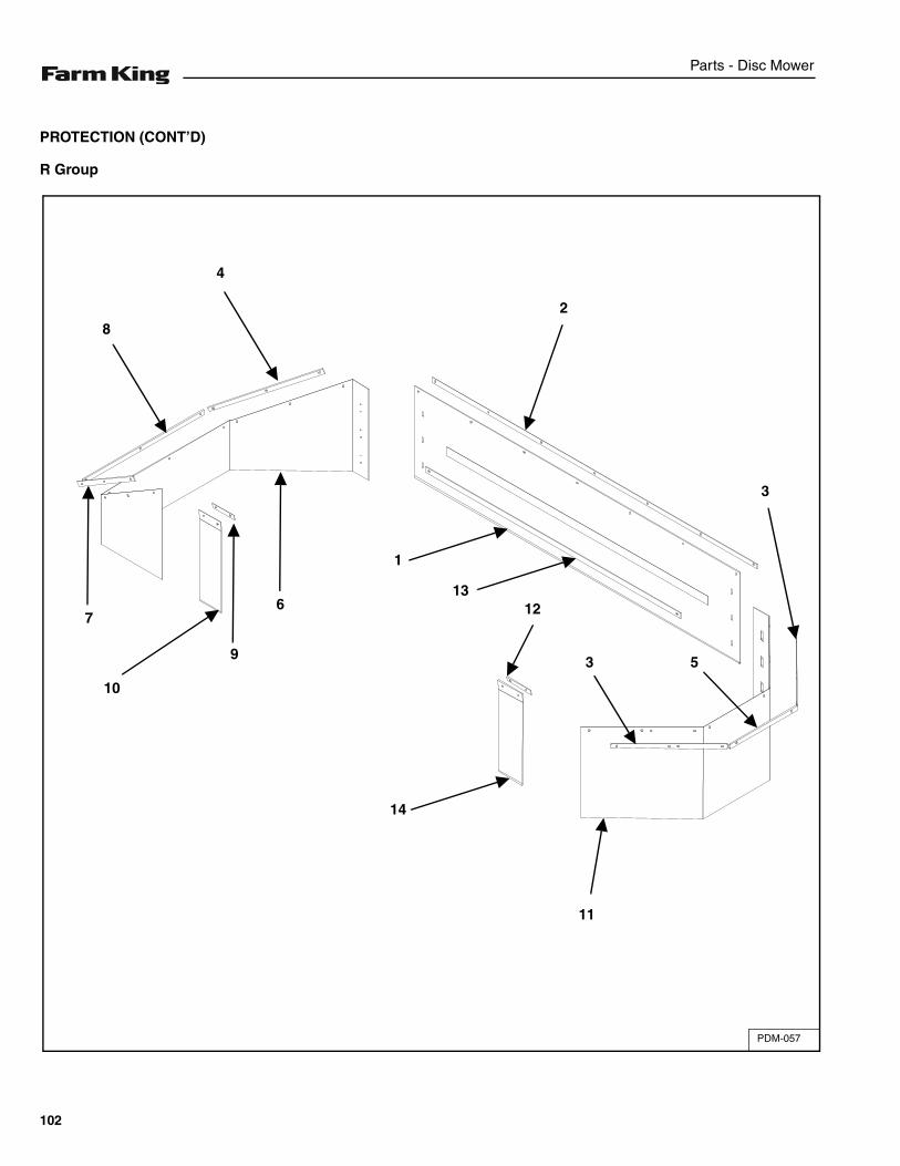
Parts - Disc Mower
PROTECTION (CONT’D)
R Group
PDM-057
3
14
11
5
3
13
1
6
10
7
8
4
2
9
12
102
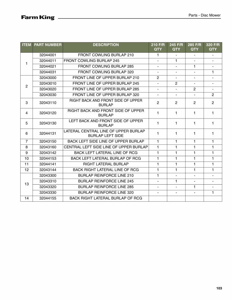
Parts - Disc Mower
ITEM PART NUMBER DESCRIPTION 210 F/R QTY
245 F/R QTY
285 F/R QTY
320 F/R QTY
1
32044001 FRONT COWLING BURLAP 210 1 - - -
32044011 FRONT COWLING BURLAP 245 - 1 - -
32044021 FRONT COWLING BURLAP 285 - - 1 -
32044031 FRONT COWLING BURLAP 320 - - - 1
2
32043000 FRONT LINE OF UPPER BURLAP 210 2 - - -
32043010 FRONT LINE OF UPPER BURLAP 245 - 2 - -
32043020 FRONT LINE OF UPPER BURLAP 285 - - 2 -
32043030 FRONT LINE OF UPPER BURLAP 320 - - - 2
3 32043110RIGHT BACK AND FRONT SIDE OF UPPER
BURLAP2 2 2 2
4 32043120RIGHT BACK AND FRONT SIDE OF UPPER
BURLAP1 1 1 1
5 32043130LEFT BACK AND FRONT SIDE OF UPPER
BURLAP1 1 1 1
6 32044131LATERAL CENTRAL LINE OF UPPER BURLAP
BURLAP LEFT SIDE1 1 1 1
7 32043150 BACK LEFT SIDE LINE OF UPPER BURLAP 1 1 1 1
8 32043160 CENTRAL LEFT SIDE LINE OF UPPER BURLAP 1 1 1 1
9 32043142 BACK LEFT LATERAL LINE OF RCG 1 1 1 1
10 32044153 BACK LEFT LATERAL BURLAP OF RCG 1 1 1 1
11 32044141 RIGHT LATERAL BURLAP 1 1 1 1
12 32043144 BACK RIGHT LATERAL LINE OF RCG 1 1 1 1
13
32043300 BURLAP REINFORCE LINE 210 1 - - -
32043310 BURLAP REINFORCE LINE 245 - 1 - -
32043320 BURLAP REINFORCE LINE 285 - - 1 -
32043330 BURLAP REINFORCE LINE 320 - - - 1
14 32044155 BACK RIGHT LATERAL BURLAP OF RCG
103
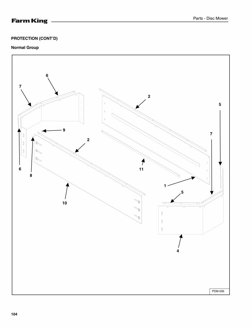
Parts - Disc Mower
PROTECTION (CONT’D)
Normal Group
PDM-056
2
6
7
2
6
10
11
1
5
7
5
9
8
4
104
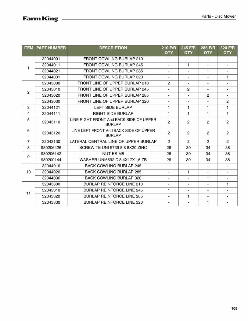
Parts - Disc Mower
ITEM PART NUMBER DESCRIPTION 210 F/R QTY
245 F/R QTY
285 F/R QTY
320 F/R QTY
1
32044001 FRONT COWLING BURLAP 210 1 - - -
32044011 FRONT COWLING BURLAP 245 - 1 - -
32044021 FRONT COWLING BURLAP 285 - - 1 -
32044031 FRONT COWLING BURLAP 320 - - - 1
2
32043000 FRONT LINE OF UPPER BURLAP 210 2 - - -
32043010 FRONT LINE OF UPPER BURLAP 245 - 2 - -
32043020 FRONT LINE OF UPPER BURLAP 285 - - 2 -
32043030 FRONT LINE OF UPPER BURLAP 320 - - - 2
3 32044121 LEFT SIDE BURLAP 1 1 1 1
4 32044111 RIGHT SIDE BURLAP 1 1 1 1
532043110
LINE RIGHT FRONT And BACK SIDE OF UPPER BURLAP
2 2 2 2
632043120
LINE LEFT FRONT And BACK SIDE OF UPPER BURLAP
2 2 2 2
7 32043130 LATERAL CENTRAL LINE OF UPPER BURLAP 2 2 2 2
8 980206426 SCREW TE UNI 5739 8.8 8X20 ZINC 26 30 34 38
9980206142 NUT ES M8 26 30 34 38
980200144 WASHER UNI6592 D.8,4X17X1,6 ZB 26 30 34 38
10
32044016 BACK COWLING BURLAP 245 1 - - -
32044026 BACK COWLING BURLAP 285 - 1 - -
32044036 BACK COWLING BURLAP 320 - - 1 -
11
32043300 BURLAP REINFORCE LINE 210 - - - 1
32043310 BURLAP REINFORCE LINE 245 1 - - -
32043320 BURLAP REINFORCE LINE 285 - 1 - -
32043330 BURLAP REINFORCE LINE 320 - - 1 -
105
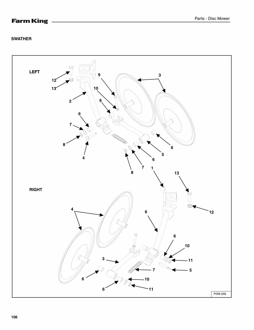
Parts - Disc Mower
SWATHER
PDM-058
3LEFT
RIGHT
LEFT9
12
13
2
10
6
6
7
8
4
87
65
6
113
64
6
3
6 11
10
7 5
11
10
6
12
106
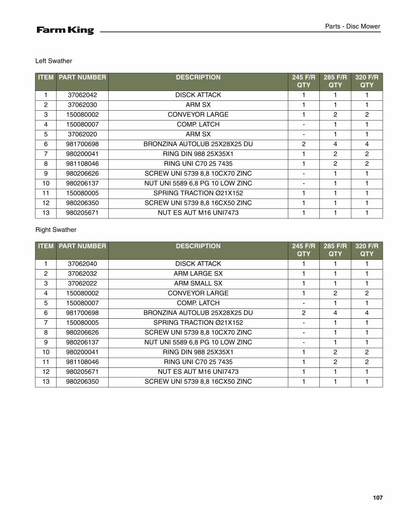
Parts - Disc Mower
Left Swather
Right Swather
ITEM PART NUMBER DESCRIPTION 245 F/R QTY
285 F/R QTY
320 F/R QTY
1 37062042 DISCK ATTACK 1 1 1
2 37062030 ARM SX 1 1 1
3 150080002 CONVEYOR LARGE 1 2 2
4 150080007 COMP. LATCH - 1 1
5 37062020 ARM SX - 1 1
6 981700698 BRONZINA AUTOLUB 25X28X25 DU 2 4 4
7 980200041 RING DIN 988 25X35X1 1 2 2
8 981108046 RING UNI C70 25 7435 1 2 2
9 980206626 SCREW UNI 5739 8,8 10CX70 ZINC - 1 1
10 980206137 NUT UNI 5589 6,8 PG 10 LOW ZINC - 1 1
11 150080005 SPRING TRACTION Ø21X152 1 1 1
12 980206350 SCREW UNI 5739 8,8 16CX50 ZINC 1 1 1
13 980205671 NUT ES AUT M16 UNI7473 1 1 1
ITEM PART NUMBER DESCRIPTION 245 F/R QTY
285 F/R QTY
320 F/R QTY
1 37062040 DISCK ATTACK 1 1 1
2 37062032 ARM LARGE SX 1 1 1
3 37062022 ARM SMALL SX 1 1 1
4 150080002 CONVEYOR LARGE 1 2 2
5 150080007 COMP. LATCH - 1 1
6 981700698 BRONZINA AUTOLUB 25X28X25 DU 2 4 4
7 150080005 SPRING TRACTION Ø21X152 - 1 1
8 980206626 SCREW UNI 5739 8,8 10CX70 ZINC - 1 1
9 980206137 NUT UNI 5589 6,8 PG 10 LOW ZINC - 1 1
10 980200041 RING DIN 988 25X35X1 1 2 2
11 981108046 RING UNI C70 25 7435 1 2 2
12 980205671 NUT ES AUT M16 UNI7473 1 1 1
13 980206350 SCREW UNI 5739 8,8 16CX50 ZINC 1 1 1
107
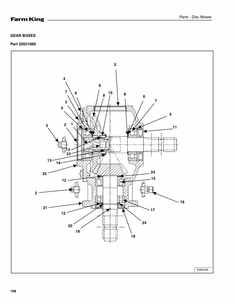
Parts - Disc Mower
GEAR BOXES
Part 32031060
PDM-059
2
8
9
6
4
78
67
5
11
24
15
16
17
24
1819
20
1221
3
22
1413
13
3 2
3
5
1
10
23
12
108
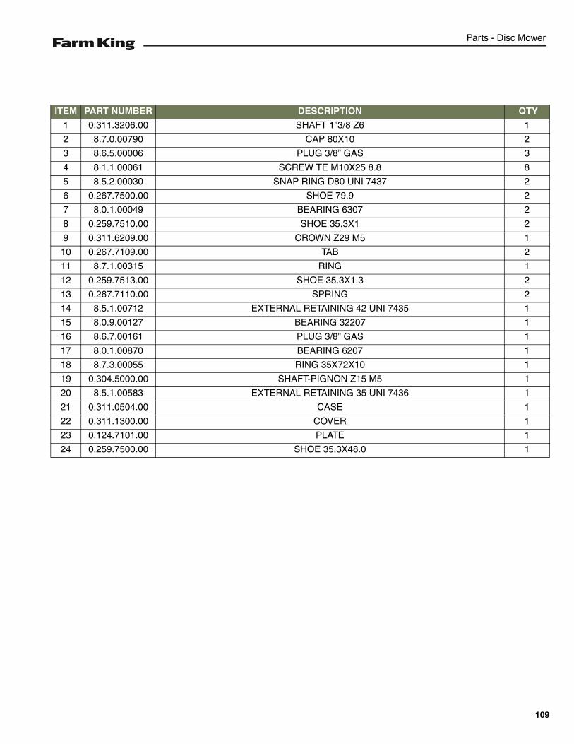
Parts - Disc Mower
ITEM PART NUMBER DESCRIPTION QTY
1 0.311.3206.00 SHAFT 1”3/8 Z6 1
2 8.7.0.00790 CAP 80X10 2
3 8.6.5.00006 PLUG 3/8” GAS 3
4 8.1.1.00061 SCREW TE M10X25 8.8 8
5 8.5.2.00030 SNAP RING D80 UNI 7437 2
6 0.267.7500.00 SHOE 79.9 2
7 8.0.1.00049 BEARING 6307 2
8 0.259.7510.00 SHOE 35.3X1 2
9 0.311.6209.00 CROWN Z29 M5 1
10 0.267.7109.00 TAB 2
11 8.7.1.00315 RING 1
12 0.259.7513.00 SHOE 35.3X1.3 2
13 0.267.7110.00 SPRING 2
14 8.5.1.00712 EXTERNAL RETAINING 42 UNI 7435 1
15 8.0.9.00127 BEARING 32207 1
16 8.6.7.00161 PLUG 3/8” GAS 1
17 8.0.1.00870 BEARING 6207 1
18 8.7.3.00055 RING 35X72X10 1
19 0.304.5000.00 SHAFT-PIGNON Z15 M5 1
20 8.5.1.00583 EXTERNAL RETAINING 35 UNI 7436 1
21 0.311.0504.00 CASE 1
22 0.311.1300.00 COVER 1
23 0.124.7101.00 PLATE 1
24 0.259.7500.00 SHOE 35.3X48.0 1
109
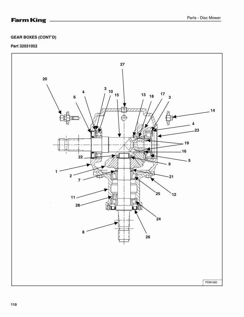
Parts - Disc Mower
GEAR BOXES (CONT’D)
Part 32031052
PDM-060
14
4
23
19
16
59
21
1225
24
268
28
11
72
1
22
20
64
310
15
27
13 18 173
110
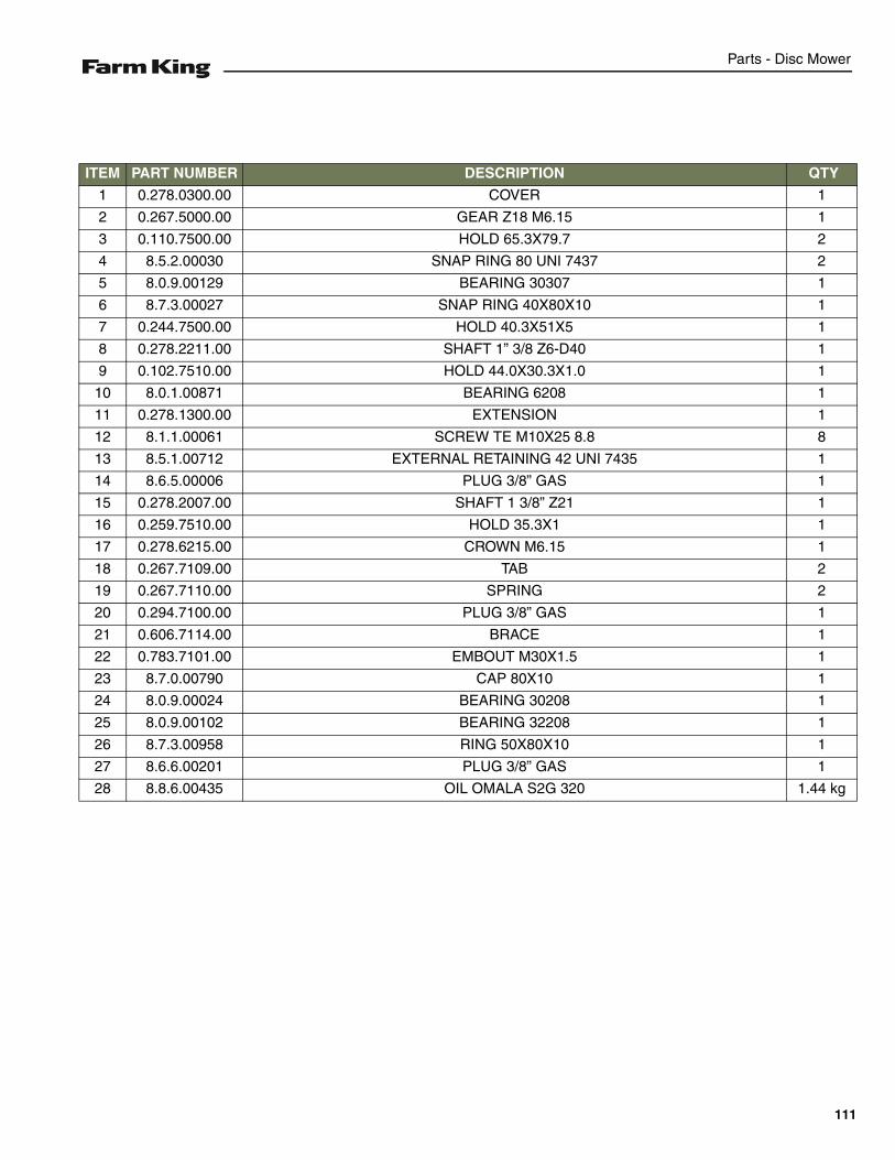
Parts - Disc Mower
ITEM PART NUMBER DESCRIPTION QTY
1 0.278.0300.00 COVER 1
2 0.267.5000.00 GEAR Z18 M6.15 1
3 0.110.7500.00 HOLD 65.3X79.7 2
4 8.5.2.00030 SNAP RING 80 UNI 7437 2
5 8.0.9.00129 BEARING 30307 1
6 8.7.3.00027 SNAP RING 40X80X10 1
7 0.244.7500.00 HOLD 40.3X51X5 1
8 0.278.2211.00 SHAFT 1” 3/8 Z6-D40 1
9 0.102.7510.00 HOLD 44.0X30.3X1.0 1
10 8.0.1.00871 BEARING 6208 1
11 0.278.1300.00 EXTENSION 1
12 8.1.1.00061 SCREW TE M10X25 8.8 8
13 8.5.1.00712 EXTERNAL RETAINING 42 UNI 7435 1
14 8.6.5.00006 PLUG 3/8” GAS 1
15 0.278.2007.00 SHAFT 1 3/8” Z21 1
16 0.259.7510.00 HOLD 35.3X1 1
17 0.278.6215.00 CROWN M6.15 1
18 0.267.7109.00 TAB 2
19 0.267.7110.00 SPRING 2
20 0.294.7100.00 PLUG 3/8” GAS 1
21 0.606.7114.00 BRACE 1
22 0.783.7101.00 EMBOUT M30X1.5 1
23 8.7.0.00790 CAP 80X10 1
24 8.0.9.00024 BEARING 30208 1
25 8.0.9.00102 BEARING 32208 1
26 8.7.3.00958 RING 50X80X10 1
27 8.6.6.00201 PLUG 3/8” GAS 1
28 8.8.6.00435 OIL OMALA S2G 320 1.44 kg
111
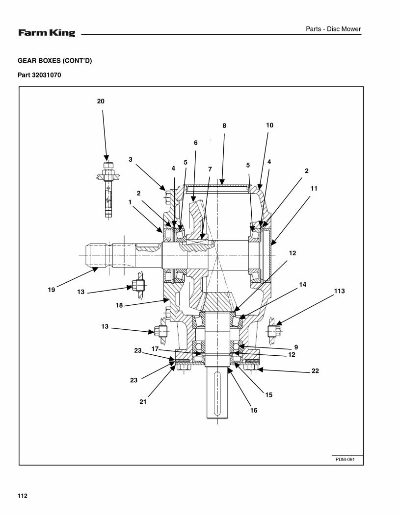
Parts - Disc Mower
GEAR BOXES (CONT’D)
Part 32031070
PDM-061
3
20
45
6
8
7
10
5 42
11
12
14113
912
22
15
1621
23
23 17
13
18
1319
12
112
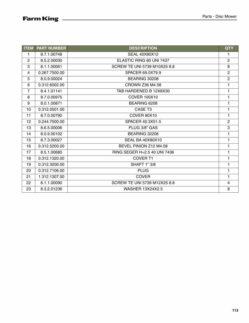
Parts - Disc Mower
ITEM PART NUMBER DESCRIPTION QTY
1 8.7.1.00748 SEAL 40X80X12 1
2 8.5.2.00030 ELASTIC RING 80 UNI 7437 2
3 8.1.1.00061 SCREW TE UNI 5739 M10X25 8.8 8
4 0.267.7500.00 SPACER 69.0X79.9 2
5 8.0.9.00024 BEARING 30208 2
6 0.312.6002.00 CROWN Z36 M4.58 1
7 8.4.1.01141 TAB HARDENED B 12X8X30 1
8 8.7.0.00975 COVER 100X10 1
9 8.0.1.00871 BEARING 6208 1
10 0.312.0501.00 CASE T3 1
11 8.7.0.00790 COVER 80X10 1
12 0.244.7500.00 SPACER 40.3X51.5 2
13 8.6.5.00006 PLUG 3/8” GAS 3
14 8.0.9.00102 BEARING 32208 1
15 8.7.3.00027 SEAL BA 40X80X10 1
16 0.312.5200.00 BEVEL PINION Z12 M4.58 1
17 8.5.1.00680 RING SEGER H=2.5 40 UNI 7436 1
18 0.312.1320.00 COVER T1 1
19 0.312.3200.00 SHAFT 1” 3/8 1
20 0.312.7106.00 PLUG 1
21 1.312.1307.00 COVER 1
22 8.1.1.00090 SCREW TE UNI 5739 M12X25 8.8 4
23 8.3.2.01236 WASHER 13X24X2.5 8
113
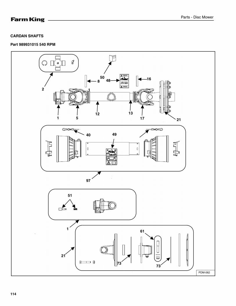
Parts - Disc Mower
CARDAN SHAFTS
Part 989931015 540 RPM
PDM-062
12
850
48 16
21
40 49
171312
51
97
51
1
21
73
61
73
114
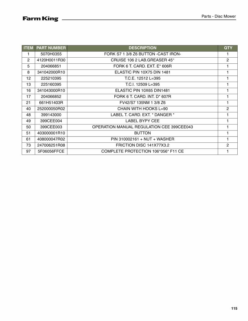
Parts - Disc Mower
ITEM PART NUMBER DESCRIPTION QTY
1 5070H0355 FORK S7 1 3/8 Z6 BUTTON -CAST IRON- 1
2 4120H0011R30 CRUISE 106 2 LAB.GREASER 45° 2
5 204066851 FORK 6 T. CARD. EXT. E* 606R 1
8 341042000R10 ELASTIC PIN 10X75 DIN 1481 1
12 225210395 T.C.E. 12512 L=395 1
13 225160395 T.C.I. 12509 L=395 1
16 341043000R10 ELASTIC PIN 10X65 DIN1481 1
17 204066852 FORK 6 T. CARD. INT. D* 607R 1
21 661H51403R FV42/S7 135NM 1 3/8 Z6 1
40 252000050R02 CHAIN WITH HOOKS L=90 2
48 399143000 LABEL T. CARD. EXT. * DANGER * 1
49 399CEE004 LABEL BYPY CEE 1
50 399CEE003 OPERATION MANUAL REGULATION CEE 399CEE043 1
51 403000001R10 BUTTON 1
61 408000047R02 PIN 310002161 + NUT + WASHER 1
73 247006251R08 FRICTION DISC 141X77X3.2 2
97 5F06056FFCE COMPLETE PROTECTION 106*056* F11 CE 1
115
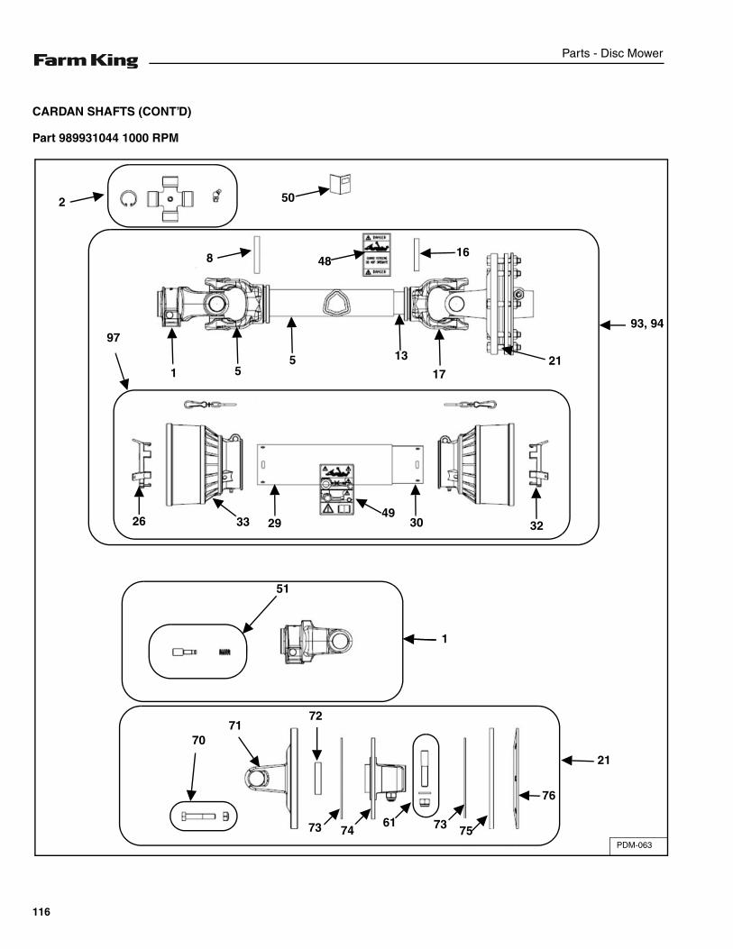
Parts - Disc Mower
CARDAN SHAFTS (CONT’D)
Part 989931044 1000 RPM
PDM-063
2 50
8 4816
97
1 55 13
1721
323049
293326
51
21
7071
72
73 7461 73 75
76
93, 94
1
116
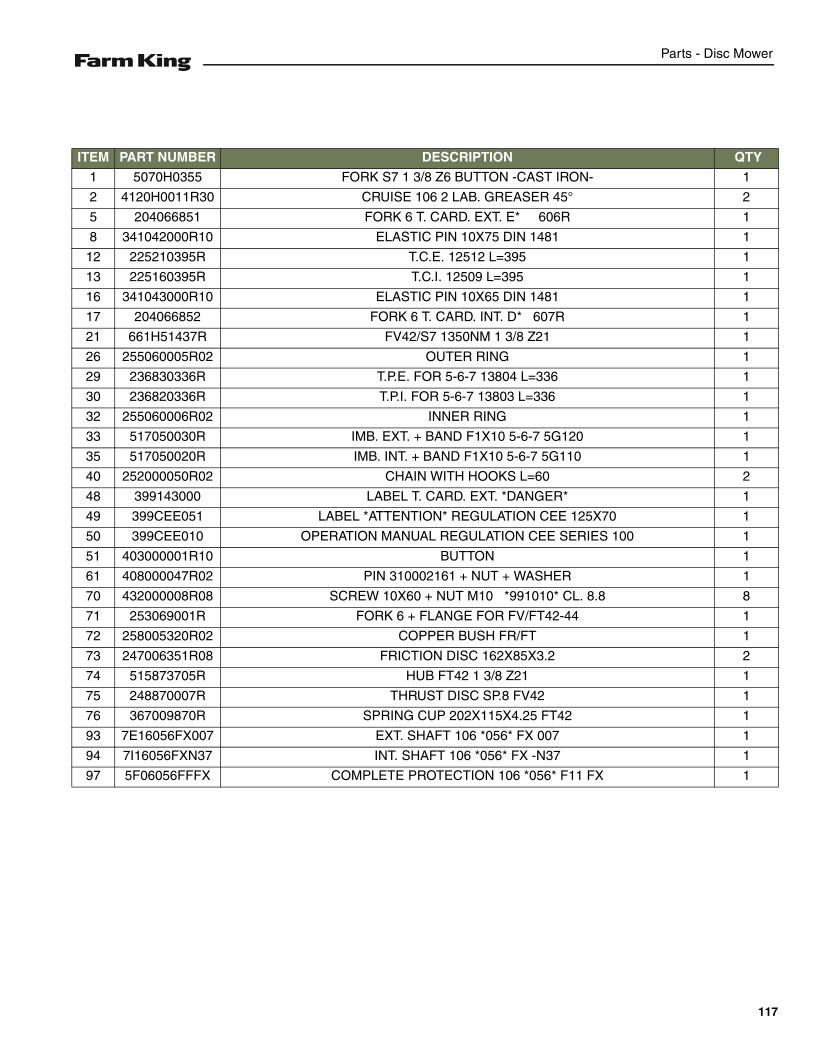
Parts - Disc Mower
ITEM PART NUMBER DESCRIPTION QTY
1 5070H0355 FORK S7 1 3/8 Z6 BUTTON -CAST IRON- 1
2 4120H0011R30 CRUISE 106 2 LAB. GREASER 45° 2
5 204066851 FORK 6 T. CARD. EXT. E* 606R 1
8 341042000R10 ELASTIC PIN 10X75 DIN 1481 1
12 225210395R T.C.E. 12512 L=395 1
13 225160395R T.C.I. 12509 L=395 1
16 341043000R10 ELASTIC PIN 10X65 DIN 1481 1
17 204066852 FORK 6 T. CARD. INT. D* 607R 1
21 661H51437R FV42/S7 1350NM 1 3/8 Z21 1
26 255060005R02 OUTER RING 1
29 236830336R T.P.E. FOR 5-6-7 13804 L=336 1
30 236820336R T.P.I. FOR 5-6-7 13803 L=336 1
32 255060006R02 INNER RING 1
33 517050030R IMB. EXT. + BAND F1X10 5-6-7 5G120 1
35 517050020R IMB. INT. + BAND F1X10 5-6-7 5G110 1
40 252000050R02 CHAIN WITH HOOKS L=60 2
48 399143000 LABEL T. CARD. EXT. *DANGER* 1
49 399CEE051 LABEL *ATTENTION* REGULATION CEE 125X70 1
50 399CEE010 OPERATION MANUAL REGULATION CEE SERIES 100 1
51 403000001R10 BUTTON 1
61 408000047R02 PIN 310002161 + NUT + WASHER 1
70 432000008R08 SCREW 10X60 + NUT M10 *991010* CL. 8.8 8
71 253069001R FORK 6 + FLANGE FOR FV/FT42-44 1
72 258005320R02 COPPER BUSH FR/FT 1
73 247006351R08 FRICTION DISC 162X85X3.2 2
74 515873705R HUB FT42 1 3/8 Z21 1
75 248870007R THRUST DISC SP.8 FV42 1
76 367009870R SPRING CUP 202X115X4.25 FT42 1
93 7E16056FX007 EXT. SHAFT 106 *056* FX 007 1
94 7I16056FXN37 INT. SHAFT 106 *056* FX -N37 1
97 5F06056FFFX COMPLETE PROTECTION 106 *056* F11 FX 1
117
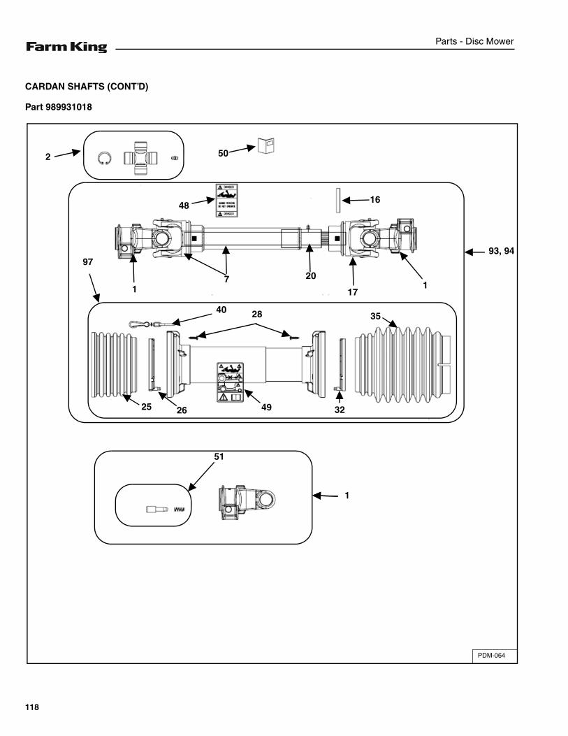
Parts - Disc Mower
CARDAN SHAFTS (CONT’D)
Part 989931018
PDM-064
2 50
4816
97
1
40
7 20
171
35
32492625
51
93, 94
1
28
118
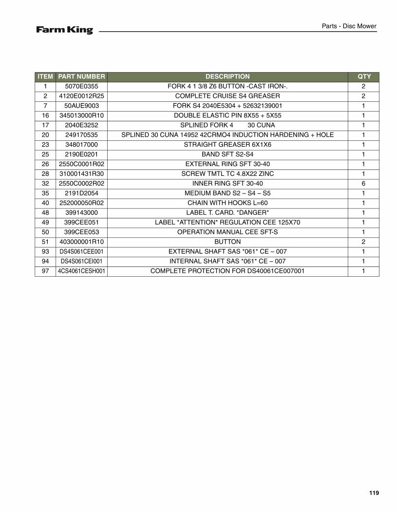
Parts - Disc Mower
ITEM PART NUMBER DESCRIPTION QTY
1 5070E0355 FORK 4 1 3/8 Z6 BUTTON -CAST IRON-. 2
2 4120E0012R25 COMPLETE CRUISE S4 GREASER 2
7 50AUE9003 FORK S4 2040E5304 + 52632139001 1
16 345013000R10 DOUBLE ELASTIC PIN 8X55 + 5X55 1
17 2040E3252 SPLINED FORK 4 30 CUNA 1
20 249170535 SPLINED 30 CUNA 14952 42CRMO4 INDUCTION HARDENING + HOLE 1
23 348017000 STRAIGHT GREASER 6X1X6 1
25 2190E0201 BAND SFT S2-S4 1
26 2550C0001R02 EXTERNAL RING SFT 30-40 1
28 310001431R30 SCREW TMTL TC 4.8X22 ZINC 1
32 2550C0002R02 INNER RING SFT 30-40 6
35 2191D2054 MEDIUM BAND S2 – S4 – S5 1
40 252000050R02 CHAIN WITH HOOKS L=60 1
48 399143000 LABEL T. CARD. *DANGER* 1
49 399CEE051 LABEL *ATTENTION* REGULATION CEE 125X70 1
50 399CEE053 OPERATION MANUAL CEE SFT-S 1
51 403000001R10 BUTTON 2
93 DS4S061CEE001 EXTERNAL SHAFT SAS *061* CE – 007 1
94 DS4S061CEI001 INTERNAL SHAFT SAS *061* CE – 007 1
97 4CS4061CESH001 COMPLETE PROTECTION FOR DS40061CE007001 1
119

Parts - Disc Mower
120
Specifications - Disc Mower
SPECIFICATIONS
SPECIFICATIONS . . . . . . . . . . . . . . . . . . . . . . . . . . . . . . . . . . . . . . . . . . . . . . . . . . . . . . . . . . . . . 123Dimensions . . . . . . . . . . . . . . . . . . . . . . . . . . . . . . . . . . . . . . . . . . . . . . . . . . . . . . . . . . . . . . . . 123Performance . . . . . . . . . . . . . . . . . . . . . . . . . . . . . . . . . . . . . . . . . . . . . . . . . . . . . . . . . . . . . . . 123
HARDWARE TORQUE VALUES . . . . . . . . . . . . . . . . . . . . . . . . . . . . . . . . . . . . . . . . . . . . . . . . . . 124Metric Chart . . . . . . . . . . . . . . . . . . . . . . . . . . . . . . . . . . . . . . . . . . . . . . . . . . . . . . . . . . . . . . . 124Imperial Chart . . . . . . . . . . . . . . . . . . . . . . . . . . . . . . . . . . . . . . . . . . . . . . . . . . . . . . . . . . . . . . 125
HYDRAULIC CONNECTION SPECIFICATIONS . . . . . . . . . . . . . . . . . . . . . . . . . . . . . . . . . . . . . .126O-Ring Fitting (Straight Thread) . . . . . . . . . . . . . . . . . . . . . . . . . . . . . . . . . . . . . . . . . . . . . . . .126O-ring Face Seal Connection . . . . . . . . . . . . . . . . . . . . . . . . . . . . . . . . . . . . . . . . . . . . . . . . . . 126Flare Fitting . . . . . . . . . . . . . . . . . . . . . . . . . . . . . . . . . . . . . . . . . . . . . . . . . . . . . . . . . . . . . . . . 126Port Seal (O-ring Boss) Fitting . . . . . . . . . . . . . . . . . . . . . . . . . . . . . . . . . . . . . . . . . . . . . . . . . 126Tubelines And Hoses . . . . . . . . . . . . . . . . . . . . . . . . . . . . . . . . . . . . . . . . . . . . . . . . . . . . . . . . 126
121

Specifications - Disc Mower
122
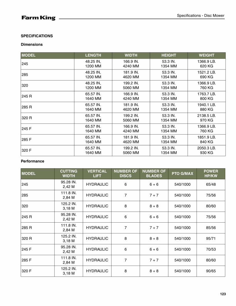
Specifications - Disc Mower
SPECIFICATIONS
Dimensions
Performance
MODEL LENGTH WIDTH HEIGHT WEIGHT
24548.25 IN,1200 MM
166.9 IN.4240 MM
53.3 IN.1354 MM
1366.9 LB.620 KG
28548.25 IN,1200 MM
181.9 IN.4620 MM
53.3 IN.1354 MM
1521.2 LB.690 KG
32048.25 IN,1200 MM
199.2 IN.5060 MM
53.3 IN.1354 MM
1366.9 LB.760 KG
245 R65.57 IN.1640 MM
166.9 IN.4240 MM
53.3 IN.1354 MM
1763.7 LB.800 KG
285 R65.57 IN.1640 MM
181.9 IN.4620 MM
53.3 IN.1354 MM
1940.1 LB.880 KG
320 R65.57 IN.1640 MM
199.2 IN.5060 MM
53.3 IN.1354 MM
2138.5 LB.970 KG
245 F65.57 IN.1640 MM
166.9 IN.4240 MM
53.3 IN.1354 MM
1366.9 LB.760 KG
285 F65.57 IN.1640 MM
181.9 IN.4620 MM
53.3 IN.1354 MM
1851.9 LB.840 KG
320 F65.57 IN.1640 MM
199.2 IN.5060 MM
53.3 IN.1354 MM
2050.3 LB.930 KG
MODELCUTTING
WIDTHVERTICAL
LIFTNUMBER OF
DISCSNUMBER OF
BLADESPTO G/MAX
POWER HP/KW
24595.28 IN.2,42 M
HYDRAULIC 6 6 + 6 540/1000 65/48
285111.8 IN.2,84 M
HYDRAULIC 7 7 + 7 540/1000 75/56
320125.2 IN.3,18 M
HYDRAULIC 8 8 + 8 540/1000 80/60
245 R95.28 IN.2,42 M
HYDRAULIC 6 6 + 6 540/1000 75/56
285 R111.8 IN.2,84 M
HYDRAULIC 7 7 + 7 540/1000 85/56
320 R125.2 IN.3,18 M
HYDRAULIC 8 8 + 8 540/1000 95/71
245 F95.28 IN.2,42 M
HYDRAULIC 6 6 + 6 540/1000 70/53
285 F111.8 IN.2,84 M
HYDRAULIC 7 7 + 7 540/1000 80/60
320 F125.2 IN.3,18 M
HYDRAULIC 8 8 + 8 540/1000 90/65
123
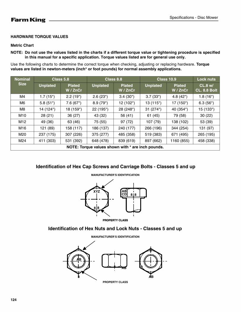
Specifications - Disc Mower
HARDWARE TORQUE VALUES
Metric Chart
NOTE: Do not use the values listed in the charts if a different torque value or tightening procedure is specifiedin this manual for a specific application. Torque values listed are for general use only.
Use the following charts to determine the correct torque when checking, adjusting or replacing hardware. Torquevalues are listed in newton-meters (inch* or foot pounds) for normal assembly applications.
Nominal Size
Class 5.8 Class 8.8 Class 10.9 Lock nuts
Unplated PlatedW / ZnCr
Unplated PlatedW / ZnCr
Unplated PlatedW / ZnCr
CL.8 w/CL. 8.8 Bolt
M4 1.7 (15*) 2.2 (19*) 2.6 (23*) 3.4 (30*) 3.7 (33*) 4.8 (42*) 1.8 (16*)
M6 5.8 (51*) 7.6 (67*) 8.9 (79*) 12 (102*) 13 (115*) 17 (150*) 6.3 (56*)
M8 14 (124*) 18 (159*) 22 (195*) 28 (248*) 31 (274*) 40 (354*) 15 (133*)
M10 28 (21) 36 (27) 43 (32) 56 (41) 61 (45) 79 (58) 30 (22)
M12 49 (36) 63 (46) 75 (55) 97 (72) 107 (79) 138 (102) 53 (39)
M16 121 (89) 158 (117) 186 (137) 240 (177) 266 (196) 344 (254) 131 (97)
M20 237 (175) 307 (226) 375 (277) 485 (358) 519 (383) 671 (495) 265 (195)
M24 411 (303) 531 (392) 648 (478) 839 (619) 897 (662) 1160 (855) 458 (338)
NOTE: Torque values shown with * are inch pounds.
Identification of Hex Cap Screws and Carriage Bolts - Classes 5 and up
XYZ
8 8
8 8ABCD
MANUFACTURER’S IDENTIFICATION
PROPERTY CLASS
Identification of Hex Nuts and Lock Nuts - Classes 5 and up
PROPERTY CLASS
MANUFACTURER’S IDENTIFICATION
PROPERTY CLASS
AB
AB8
8 AB
124
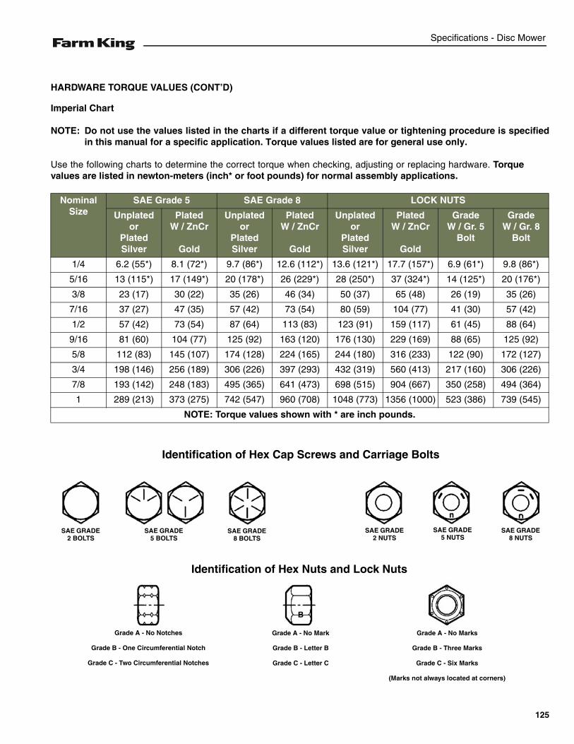
Specifications - Disc Mower
HARDWARE TORQUE VALUES (CONT’D)
Imperial Chart
NOTE: Do not use the values listed in the charts if a different torque value or tightening procedure is specifiedin this manual for a specific application. Torque values listed are for general use only.
Use the following charts to determine the correct torque when checking, adjusting or replacing hardware. Torquevalues are listed in newton-meters (inch* or foot pounds) for normal assembly applications.
Nominal Size
SAE Grade 5 SAE Grade 8 LOCK NUTS
Unplatedor
Plated Silver
PlatedW / ZnCr
Gold
Unplatedor
Plated Silver
PlatedW / ZnCr
Gold
Unplatedor
Plated Silver
PlatedW / ZnCr
Gold
GradeW / Gr. 5
Bolt
GradeW / Gr. 8
Bolt
1/4 6.2 (55*) 8.1 (72*) 9.7 (86*) 12.6 (112*) 13.6 (121*) 17.7 (157*) 6.9 (61*) 9.8 (86*)
5/16 13 (115*) 17 (149*) 20 (178*) 26 (229*) 28 (250*) 37 (324*) 14 (125*) 20 (176*)
3/8 23 (17) 30 (22) 35 (26) 46 (34) 50 (37) 65 (48) 26 (19) 35 (26)
7/16 37 (27) 47 (35) 57 (42) 73 (54) 80 (59) 104 (77) 41 (30) 57 (42)
1/2 57 (42) 73 (54) 87 (64) 113 (83) 123 (91) 159 (117) 61 (45) 88 (64)
9/16 81 (60) 104 (77) 125 (92) 163 (120) 176 (130) 229 (169) 88 (65) 125 (92)
5/8 112 (83) 145 (107) 174 (128) 224 (165) 244 (180) 316 (233) 122 (90) 172 (127)
3/4 198 (146) 256 (189) 306 (226) 397 (293) 432 (319) 560 (413) 217 (160) 306 (226)
7/8 193 (142) 248 (183) 495 (365) 641 (473) 698 (515) 904 (667) 350 (258) 494 (364)
1 289 (213) 373 (275) 742 (547) 960 (708) 1048 (773) 1356 (1000) 523 (386) 739 (545)
NOTE: Torque values shown with * are inch pounds.
Identification of Hex Cap Screws and Carriage Bolts
Identification of Hex Nuts and Lock Nuts
SAE GRADE 2 BOLTS
SAE GRADE 5 BOLTS
SAE GRADE 8 BOLTS
SAE GRADE 2 NUTS
SAE GRADE 5 NUTS
SAE GRADE 8 NUTS
B
Grade A - No Notches
Grade B - One Circumferential Notch
Grade C - Two Circumferential Notches
Grade A - No Mark
Grade B - Letter B
Grade C - Letter C
Grade A - No Marks
Grade B - Three Marks
Grade C - Six Marks
(Marks not always located at corners)
125
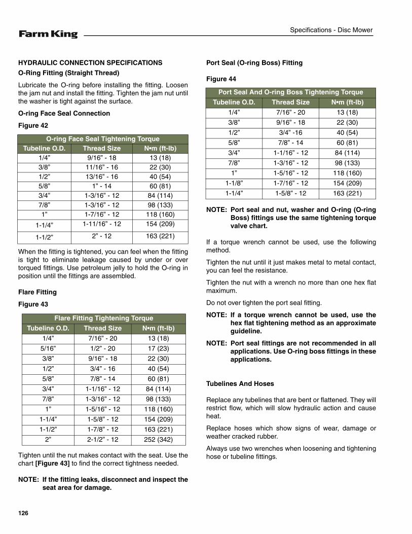
Specifications - Disc Mower
HYDRAULIC CONNECTION SPECIFICATIONS
O-Ring Fitting (Straight Thread)
Lubricate the O-ring before installing the fitting. Loosenthe jam nut and install the fitting. Tighten the jam nut untilthe washer is tight against the surface.
O-ring Face Seal Connection
Figure 42
When the fitting is tightened, you can feel when the fittingis tight to eliminate leakage caused by under or overtorqued fittings. Use petroleum jelly to hold the O-ring inposition until the fittings are assembled.
Flare Fitting
Figure 43
Tighten until the nut makes contact with the seat. Use thechart [Figure 43] to find the correct tightness needed.
NOTE: If the fitting leaks, disconnect and inspect theseat area for damage.
Port Seal (O-ring Boss) Fitting
Figure 44
NOTE: Port seal and nut, washer and O-ring (O-ringBoss) fittings use the same tightening torquevalve chart.
If a torque wrench cannot be used, use the followingmethod.
Tighten the nut until it just makes metal to metal contact,you can feel the resistance.
Tighten the nut with a wrench no more than one hex flatmaximum.
Do not over tighten the port seal fitting.
NOTE: If a torque wrench cannot be used, use thehex flat tightening method as an approximateguideline.
NOTE: Port seal fittings are not recommended in allapplications. Use O-ring boss fittings in theseapplications.
Tubelines And Hoses
Replace any tubelines that are bent or flattened. They willrestrict flow, which will slow hydraulic action and causeheat.
Replace hoses which show signs of wear, damage orweather cracked rubber.
Always use two wrenches when loosening and tighteninghose or tubeline fittings.
O-ring Face Seal Tightening TorqueTubeline O.D. Thread Size N•m (ft-lb)
1/4” 9/16” - 18 13 (18)3/8” 11/16” - 16 22 (30)1/2” 13/16” - 16 40 (54)5/8” 1” - 14 60 (81)3/4” 1-3/16” - 12 84 (114)7/8” 1-3/16” - 12 98 (133)1” 1-7/16” - 12 118 (160)
1-1/4” 1-11/16” - 12 154 (209)
1-1/2” 2” - 12 163 (221)
Flare Fitting Tightening Torque
Tubeline O.D. Thread Size N•m (ft-lb)
1/4” 7/16” - 20 13 (18)
5/16” 1/2” - 20 17 (23)
3/8” 9/16” - 18 22 (30)
1/2” 3/4” - 16 40 (54)
5/8” 7/8” - 14 60 (81)
3/4” 1-1/16” - 12 84 (114)
7/8” 1-3/16” - 12 98 (133)
1” 1-5/16” - 12 118 (160)
1-1/4” 1-5/8” - 12 154 (209)
1-1/2” 1-7/8” - 12 163 (221)
2” 2-1/2” - 12 252 (342)
Port Seal And O-ring Boss Tightening Torque
Tubeline O.D. Thread Size N•m (ft-lb)
1/4” 7/16” - 20 13 (18)
3/8” 9/16” - 18 22 (30)
1/2” 3/4” -16 40 (54)
5/8” 7/8” - 14 60 (81)
3/4” 1-1/16” - 12 84 (114)
7/8” 1-3/16” - 12 98 (133)
1” 1-5/16” - 12 118 (160)
1-1/8” 1-7/16” - 12 154 (209)
1-1/4” 1-5/8” - 12 163 (221)
126

Warranty - Disc Mower
WARRANTY
WARRANTY . . . . . . . . . . . . . . . . . . . . . . . . . . . . . . . . . . . . . . . . . . . . . . . . . . . . . . . . . . . . . . . . . . 129
127

Warranty - Disc Mower
128
Warranty - Disc Mower
WARRANTY
Limited Warranty
BASE LIMITED WARRANTY
Farm King provides this warranty only to original retail purchasers of its products. Farm King warrants to suchpurchasers that all Farm King manufactured parts and components used and serviced as provided for in theOperator’s Manual shall be free from defects in materials and workmanship for a period following delivery tothe original retail purchaser of one (1) year. This limited warranty applies only to those parts and componentsmanufactured by Farm King. Parts and components manufactured by others are subject to theirmanufacturer’s warranties, if any.
Farm King will fulfill this limited warranty by, at its option, repairing or replacing any covered part that isdefective or is the result of improper workmanship, provided that the part is returned to Farm King within thirty(30) days of the date that such defect or improper workmanship is, or should have been, discovered. Partsmust be returned through the selling representative and the buyer must prepay transportation charges.
Farm King will not be responsible for repairs or replacements that are necessitated, in whole or part, by theuse of parts not manufactured by or obtained from Farm King. Under no circumstances are component partswarranted against normal wear and tear. There is no warranty on product pump seals, product pump bearings,rubber product hoses, pressure gauges, or other components that require replacement as part of normalmaintenance.
REPAIR PARTS LIMITED WARRANTY
Farm King warrants genuine Farm King replacement parts purchased after the expiration of the Farm KingLimited Warranty, and used and serviced as provided for in the Operator’s Manual, to be free from defects inmaterials or workmanship for a period of thirty (30) days from the invoice date for the parts. Farm King willfulfill this limited warranty by, at its option, repairing or replacing any covered part that is defective or is theresult of improper workmanship, provided that the part is returned to Farm King within thirty (30) days of thedate that such defect or improper workmanship is, or should have been, discovered. Such parts must beshipped to the Farm King factory at the purchaser’s expense.
WHAT IS NOT COVERED
Under no circumstances does this limited warranty cover any components or parts that have been subject tothe following: negligence; alteration or modification not approved by Farm King; misuse; improper storage;lack of reasonable and proper maintenance, service, or repair; normal wear; damage from failure to followoperating instructions; accident; and/or repairs that have been made with parts other than thosemanufactured, supplied, and / or authorized by Farm King.
AUTHORIZED DEALER AND LABOR COSTS
Repairs eligible for labor under this limited warranty must be made by Farm King or an authorized Farm Kingdealer. Farm King retains the exclusive discretion to determine whether it will pay labor costs for warrantyrepairs or replacements, and the amount of such costs that it will pay and the time in which the repairs will bemade. If Farm King determines that it will pay labor costs for warranty work, it will do so by issuing a credit tothe dealer’s or distributor’s account. Farm King will not approve or pay invoices sent for repairs that Farm Kinghas not previously approved. Warranty service does not extend the original term of this limited warranty.
129
Warranty - Disc Mower
Limited Warranty
WARRANTY REQUIREMENTS
To be covered by warranty, each new product must be registered with Farm King within thirty (30) days ofdelivery to original retail purchaser. If the customer decides to purchase replacement components before thewarranty disposition of such components is determined, Farm King will bill the customer for suchcomponents and then credit the replacement invoice for those components later determined to be covered bythis limited warranty. Any such replacement components that are determined not be covered by this limitedwarranty will be subject to the terms of the invoice and shall be paid for by the purchaser.
EXCLUSIVE EFFECT OF WARRANTY AND LIMITATION OF LIABILITY
TO THE EXTENT PERMITTED BY LAW, FARM KING DISCLAIMS ANY WARRANTIES, REPRESENTATIONS, ORPROMISES, EXPRESS OR IMPLIED, AS TO THE QUALITY, PERFORMANCE, OR FREEDOM FROM DEFECT OFTHE COMPONENTS AND PARTS COVERED BY THIS WARRANTY AND NOT SPECIFICALLY PROVIDED FORHEREIN.
TO THE EXTENT PERMITTED BY LAW, FARM KING DISCLAIMS ANY IMPLIED WARRANTIES OFMERCHANTABILITY AND FITNESS FOR A PARTICULAR PURPOSE ON ITS PRODUCTS COVERED HEREIN,AND DISCLAIMS ANY RELIANCE BY THE PURCHASER ON FARM KING’S SKILL OR JUDGMENT TO SELECTOR FURNISH GOODS FOR ANY PARTICULAR PURPOSE. THE PURCHASER’S ONLY AND EXCLUSIVEREMEDIES IN CONNECTION WITH THE BREACH OR PERFORMANCE OF ANY WARRANTY ON FARM KING’SPRODUCTS ARE THOSE SET FORTH HEREIN. IN NO EVENT SHALL FARM KING BE LIABLE FOR INCIDENTALOR CONSEQUENTIAL DAMAGES (INCLUDING, BY WAY OF EXAMPLE ONLY AND NOT LIMITATION, LOSS OFCROPS, LOSS OF PROFITS OR REVENUE, OTHER COMMERCIAL LOSSES, INCONVENIENCE, OR COST OFREPLACEMENT OF RENTAL EQUIPMENT). IN NO EVENT SHALL FARM KING’S CONTRACT OR WARRANTYLIABILITY EXCEED THE PURCHASE PRICE OF THE PRODUCT. (Note that some states do not allow limitationson how long an implied warranty lasts or the exclusion or limitation of incidental or consequential damages,so the above limitations and exclusion may not apply to you.) This warranty gives you specific legal rights andyou may also have other rights, which vary from state to state.
Farm King neither assumes nor authorizes any person or entity, including its selling representatives, toassume any other obligations or liability in connections with the sale of covered equipment, or to make anyother warranties, representations, or promises, express or implied, as to the quality, performance, or freedomfrom defect of the components and parts covered herein. No one is authorized to alter, modify, or enlarge thislimited warranty, or its exclusions, limitations and reservations.
Corrections of defects and improper workmanship in the manner, and for the applicable time periods, providedfor herein shall constitute fulfillment of all responsibilities of Farm King to the purchaser, and Farm King shallnot be liable in negligence, contract, or on any other basis with respect to the subject equipment.
This limited warranty is subject to any existing conditions of supply which may directly affect Farm King’sability to obtain materials or manufacturer replacement parts.
Buhler Industries Inc. reserves the right to make improvements in design or changes in specifications to itsproducts at anytime, without incurring any obligation to owners of units previously sold.
130
Alphabetical Index - Disc Mower
ALPHABETICAL INDEX
CARDAN SHAFTS . . . . . . . . . . . . . . . . . . . 114CLEANING AND MAINTENANCE . . . . . . . . 52CUTTER BAR . . . . . . . . . . . . . . . . . . . . . . . 82EQUIPMENT DECALS AND SIGNS . . . . . . 18EQUIPMENT IDENTIFICATION . . . . . . . . . . 10FINGER CONDITIONER . . . . . . . . . . . . . . . 86FIRE PREVENTION . . . . . . . . . . . . . . . . . . . 15FRAME GROUP . . . . . . . . . . . . . . . . . . . . . . 68GEAR BOXES . . . . . . . . . . . . . . . . . . . . . . 108GENERAL ASSEMBLY INFORMATION . . . 23GENERAL INFORMATION . . . . . . . . . . . . . 27GENERAL INFORMATION . . . . . . . . . . . . . 63HARDWARE TORQUE VALUES . . . . . . . . 124HYDRAULIC CONNECTION SPECIFICATIONS . . . . . . . . . . . . . . . . . . . 126INITIAL SET-UP . . . . . . . . . . . . . . . . . . . . . . 30OWNER’S INFORMATION . . . . . . . . . . . . . . . 9PROTECTION . . . . . . . . . . . . . . . . . . . . . . 100ROLLER CONDITIONER . . . . . . . . . . . . . . . 90SAFETY INSTRUCTIONS . . . . . . . . . . . . . . 13SAFETY SIGN-OFF FORM . . . . . . . . . . . . . 20SAFETY SIGNS (DECALS) . . . . . . . . . . . . . 17SERVICE SCHEDULE . . . . . . . . . . . . . . . . . 50SPECIFICATIONS . . . . . . . . . . . . . . . . . . . 123STORAGE AND RETURN TO SERVICE . . . 59SWATHER . . . . . . . . . . . . . . . . . . . . . . . . . 106THREE POINT HITCH . . . . . . . . . . . . . . . . . 64TRANSMISSION . . . . . . . . . . . . . . . . . . . . . 96TRANSPORTING . . . . . . . . . . . . . . . . . . . . . 43TROUBLESHOOTING . . . . . . . . . . . . . . . . . 49WARRANTY REGISTRATION FORM . . . . . . 5WARRANTY . . . . . . . . . . . . . . . . . . . . . . . . 129
131

Alphabetical Index - Disc Mower
132


301 Mountain Street SouthMorden, Manitoba Canada R6M 1X7Toll Free: 1-888-FK-80001 E-mail: [email protected]
Equipment shown is subject to change without notice.©2016 Buhler Trading Inc. Printed in Canada TSX:BUI
www.farm-king.com
![Untitled-1 [demottauction.com]€¦ · Case MD92 3pt Disc Mower CrustBuster Speed King Cotton Module Builder John Deere 5 Batwing Mower John Deere 4 Drum Hay Tedder Kello Bilt 225TSW](https://img.pdfslide.net/doc/110x75/60d26c949f186d32213ccc86/untitled-1-case-md92-3pt-disc-mower-crustbuster-speed-king-cotton-module-builder.jpg)