Embed Size (px)
Citation preview
Easy Rake
OperatOr and parts Manual
012012 Part # P4721

3
Table of Contents - Easy Rake
Table of Contents
Introduction .................................................................................................................................5
Specifications ...............................................................................................................................6
Safety ............................................................................................................................................7• Safety Instruction .............................................................................................................7• General Safety Instructions .............................................................................................8• Handling and Transportation ...........................................................................................8• Operators Responsibilities and Safety .........................................................................10
Assembly ....................................................................................................................................11• Rake Assembly ............................................................................................................... 11• Hitching to the Tractor .................................................................................................... 11• Hydraulic Connections ..................................................................................................12• Removal ..........................................................................................................................12• Storing the Rake .............................................................................................................12• Assembly ........................................................................................................................13• Assembly of Central Rake Wheels (Optional) ..............................................................33
Operation ...................................................................................................................................35• Preliminary Information ................................................................................................35• Operation and Use .........................................................................................................35• Kicker Wheel Adjustment ..............................................................................................38
Part Drawings.............................................................................................................................40• 19010506 Easy Rake 8-10-12-14 .....................................................................................40• 19010507 Easy Rake 8-10-12-14 .....................................................................................42• 19010508 Easy Rake 8-10-12-14 .....................................................................................44• 19010519 Easy Rake 14...................................................................................................46• 19010509 Easy Rake 8-10-12-14 .....................................................................................48• 19010510 Easy Rake 8-10-12-14 .....................................................................................50• 19010511 Easy Rake 8-10-12-14 .....................................................................................52• 19010512 Easy Rake 8-10-12-14 .....................................................................................54• 19010513 Easy Rake 8-10-12-14 .....................................................................................56• 19010514 Easy Rake 8-10-12-14 .....................................................................................58• 19010515 Easy Rake 8-10-12-14 .....................................................................................60• 19010516 Easy Rake (Optional) .....................................................................................62
4
Table of Contents - Easy Rake
• 19010518 Easy Rake 8-10-12-14 (Optional) ...................................................................64• 19010517 Easy Rake 8-10-12-14 (Optional) ...................................................................66• 19010555 Easy Rake 10-12-14-16-18-20 (Type-Approval) ............................................68• 19010556 Easy Rake 8-10-12-14 Autosteer ....................................................................70
Warranty .....................................................................................................................................72
Manufacturer’s statement: for technical reasons Buhler Industries Inc. reserves the right to modify machinery design and specifications provided herein without any preliminary notice. Information provided herein is of descriptive nature. Performance quality may depend on soil fertility, applied agricultural techniques, weather conditions and other factors.
5
Introduction - Easy Rake
Introduction Raking your windrows with the Farm King Easy Rake eliminates numerous field passes and provides uniform rows. The Farm King Easy Rake comes available with 10, 12 and 14 wheel tine configurations and working widths of 21, 24 and 27 respectively. Each rake wheel comes with a fully independent suspension spring and bounce adjustment chain. The adjustable chain prevents the rake wheels from gouging uneven field terrain but allow the wheels to stay closely conformed to the field surface. Keep this manual handy for frequent reference. All new operators or owners must review the manual before using the equipment and at least annually thereafter. Contact your Farm King Dealer if you need assistance, information, or additional copies of the manual. Visit our website at www.farm-king.com for a complete list of dealers in your area. The directions left, right, front and rear, as mentioned throughout this manual, are as seen facing in the direction of travel of the implement.
6
Specifications - Easy Rake
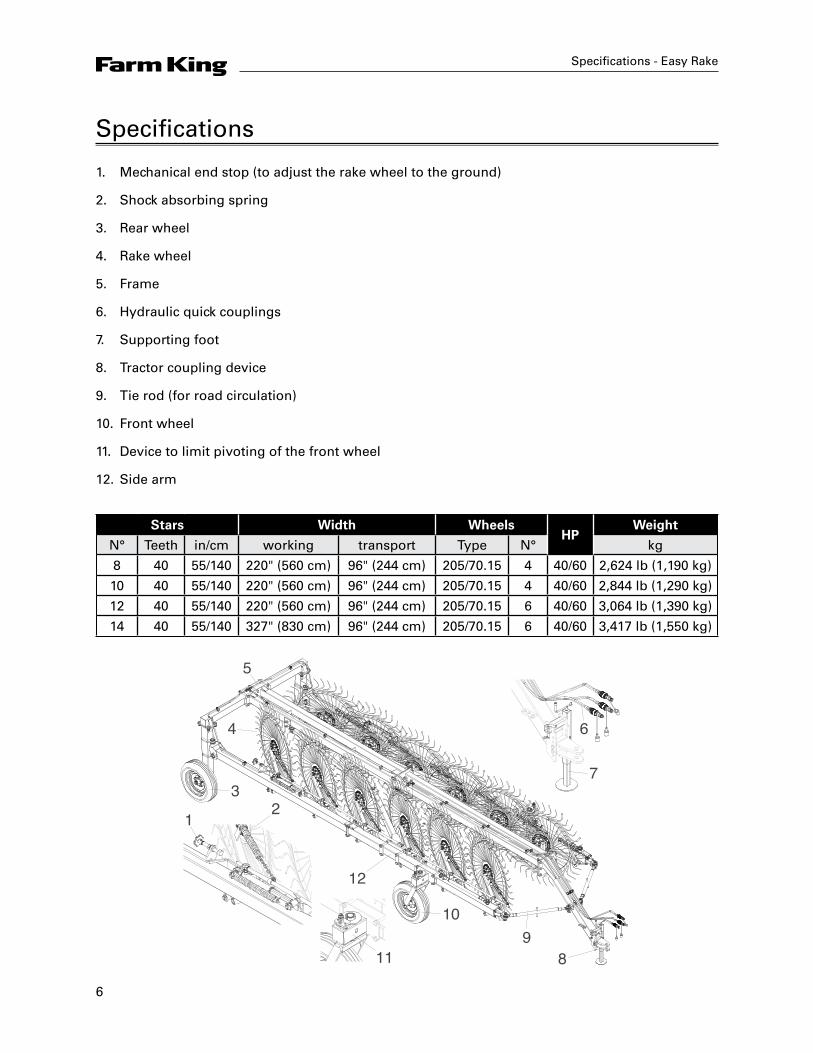
Specifications
1. Mechanical end stop (to adjust the rake wheel to the ground)
2. Shock absorbing spring
3. Rear wheel
4. Rake wheel
5. Frame
6. Hydraulic quick couplings
7. Supporting foot
8. Tractor coupling device
9. Tie rod (for road circulation)
10. Front wheel
11. Device to limit pivoting of the front wheel
12. Side arm
Stars Width WheelsHP
Weight
N° Teeth in/cm working transport Type N° kg
8 40 55/140 220" (560 cm) 96" (244 cm) 205/70.15 4 40/60 2,624 lb (1,190 kg)
10 40 55/140 220" (560 cm) 96" (244 cm) 205/70.15 4 40/60 2,844 lb (1,290 kg)
12 40 55/140 220" (560 cm) 96" (244 cm) 205/70.15 6 40/60 3,064 lb (1,390 kg)
14 40 55/140 327" (830 cm) 96" (244 cm) 205/70.15 6 40/60 3,417 lb (1,550 kg)
21
3
4
5
6
7
89
10
11
12
7
Safety - Easy Rake
Safety
Safety InstructionsRemember, YOU are the key to safety. Good safety practices not only protect you, but also the people around you. Make these practices a working part of your safety program. Be certain that everyone operating this equipment is familiar with the recommended operating and maintenance procedures and follows all the safety precautions. Most accidents can be prevented. Do not risk injury or death by ignoring good safety practices.
The alert symbol is used throughout this manual. It indicates attention is required and identifies hazards. Follow the recommended precautions.
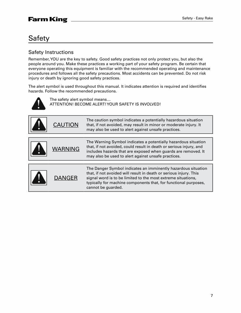
The safety alert symbol means… ATTENTION! BECOME ALERT! YOUR SAFETY IS INVOLVED!
CAUTIONThe caution symbol indicates a potentially hazardous situation that, if not avoided, may result in minor or moderate injury. It may also be used to alert against unsafe practices.
WARNINGThe Warning Symbol indicates a potentially hazardous situation that, if not avoided, could result in death or serious injury, and includes hazards that are exposed when guards are removed. It may also be used to alert against unsafe practices.
DANGER
The Danger Symbol indicates an imminently hazardous situation that, if not avoided will result in death or serious injury. This signal word is to be limited to the most extreme situations, typically for machine components that, for functional purposes, cannot be guarded.

8
Safety - Easy Rake
General Safety InstructionsThis manual describes the safety regulations to be followed when using the rake. As most work-related accidents occur due to non-compliance with the most basic of safety regulations, it is obligatory to read this manual before carrying out any work with the rake and to follow all the instructions. The equipment must be used by qualified adult personnel trained in its use. The Manufacturer therefore does not cover accidents caused by the operators negligence and/or non-compliance with the safety instructions. This also forfeits the manufacturers responsibility and the rakes warranty.
Handling and TransportationTransportation (delivery): the device is fully dismounted and placed in a crate for transportation. The Customer can then re-assemble the parts quickly and easily on receipt, following the well detailed instructions. If the rake is sold or transferred to another user, the rake can be dismantled by following the instructions in reverse order, although it can also be delivered fully assembled. The rake can also be easily transported by road on a suitable means of transport. The rake is loaded or unloaded via a ramp attached to the vehicle. The equipment, when ready for transportation, is reversed onto the vehicle, then harnessed in place and fitted with all necessary safety devices for transportation. Precautions
• Loading/unloading must be carried out on a flat surface and at a safe distance from slopes or ditches;
• Always ensure the ramps are strong enough to withstand the rakes weight (given on the identification plate), are firmly attached to the vehicle and are parallel to each other and perpendicular with the edge of the vehicle;
• Ensure the ramps are clean, without any traces of oil, grease or ice;• Never change direction when moving the rake onto or off the vehicle. If this does become
necessary, bring the rake back down to change its trajectory.
Transportation (by road): as this is a trailer-type device, it can only be transported if attached to an agricultural tractor. In this case, the device must always be in its transportation configuration for transportation either by road or in the fields, as illustrated below. This configuration is necessary as the device can be up to 33 ft (10 m) in width in its working configuration. You must remember that the transportation configuration entails closing the side arms and fitting the equipment with the following safety devices:
• Tie rods (1) to be fitted in position on the arms and frame, and locked in place with their relative safety pins;
• End stop device (2) to be inserted on the rod of the jack (to prevent it from retracting) and blocked with its respective safety pin;
• Device (3) on the front wheels to limit their movement;
You must also comply with your national road regulations.
9
Safety - Easy Rake
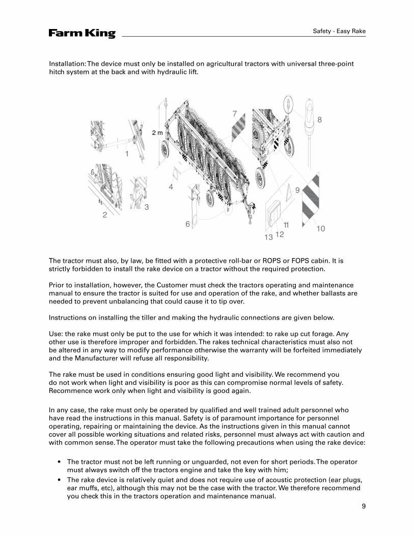
Installation: The device must only be installed on agricultural tractors with universal three-point hitch system at the back and with hydraulic lift.
2 m
1
32
613 12
11 10
9
87
4
The tractor must also, by law, be fitted with a protective roll-bar or ROPS or FOPS cabin. It is strictly forbidden to install the rake device on a tractor without the required protection. Prior to installation, however, the Customer must check the tractors operating and maintenance manual to ensure the tractor is suited for use and operation of the rake, and whether ballasts are needed to prevent unbalancing that could cause it to tip over. Instructions on installing the tiller and making the hydraulic connections are given below. Use: the rake must only be put to the use for which it was intended: to rake up cut forage. Any other use is therefore improper and forbidden. The rakes technical characteristics must also not be altered in any way to modify performance otherwise the warranty will be forfeited immediately and the Manufacturer will refuse all responsibility. The rake must be used in conditions ensuring good light and visibility. We recommend you do not work when light and visibility is poor as this can compromise normal levels of safety. Recommence work only when light and visibility is good again.
In any case, the rake must only be operated by qualified and well trained adult personnel who have read the instructions in this manual. Safety is of paramount importance for personnel operating, repairing or maintaining the device. As the instructions given in this manual cannot cover all possible working situations and related risks, personnel must always act with caution and with common sense. The operator must take the following precautions when using the rake device:
• The tractor must not be left running or unguarded, not even for short periods. The operator must always switch off the tractors engine and take the key with him;
• The rake device is relatively quiet and does not require use of acoustic protection (ear plugs, ear muffs, etc), although this may not be the case with the tractor. We therefore recommend you check this in the tractors operation and maintenance manual.

10
Safety - Easy Rake
Operator's Responsibilities and SafetySafety is of primary importance to personnel operating the rake device and therefore each operator is directly responsible for controlling the rake's operation, maintenance, repairs and/or use of spare parts or consumable materials. This means the aforementioned personnel must never delegate their work to operators without the necessary requisites.
The manufacturer assumes no liability for:
• Improper or incorrect use of the rake device that can cause harm to persons and animals or damage to objects and the actual rake;
• Employment of personnel who have not received proper training and/or has not read and understood the instructions in this manual;
• Lack of or insufficient maintenance;• Use of spare parts that are not type approved or not compatible with the rake model;
In addition to the instructions in this manual, personnel are given visual aids in the form of labels (shown in the illustration) attached to the front of the rake device indicating the necessary safety precautions. These labels are designed to attract the operator's attention and indicate the level of risk.
These labels, however, differ in shape and colour according to the instructions. Personnel must therefore know that a circular label indicates an obligation (blue and white) or a prohibition (red, white and black), and a triangular label indicates a hazard (yellow and black). Rectangular labels feature the hazard or prohibition symbol but also indicate the safety precautions to be taken.
Warnings given on the labels:
• A - Risk of flying objects. Objects in the field of operation may be caught and thrown by the teeth of the rotating rake wheels;
• B - Risk of snagging. As the rake wheel rotates, there is a risk that the teeth snag on the operator's clothes or other objects on the operator's body.
• C - Obligation to read the user and maintenance manual;
• D - Prohibition for unauthorized persons to stand or move in the rake's field of operation when the rake is being used. Persons must keep at a safe distance and should they need to move in the rake's field of operation, they must do taking all due precautions;
Important: Warning labels and pictograms must be replaced if they become faded and risk becoming illegible. In this case, the operator must not use the rake until any faded labels are replaced with new ones. It is also strictly forbidden to remove the pictograms and labels from the equipment. Should this occur, the Manufacturer assumes no liability as the rake no longer meets the safety requirements for which it was designed and created.
11
Assembly Instructions
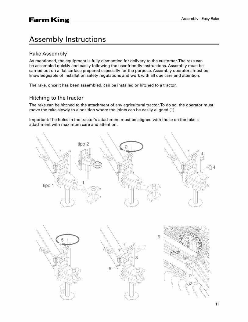
Rake AssemblyAs mentioned, the equipment is fully dismantled for delivery to the customer. The rake can be assembled quickly and easily following the user-friendly instructions. Assembly must be carried out on a flat surface prepared especially for the purpose. Assembly operators must be knowledgeable of installation safety regulations and work with all due care and attention. The rake, once it has been assembled, can be installed or hitched to a tractor.
Hitching to the TractorThe rake can be hitched to the attachment of any agricultural tractor. To do so, the operator must move the rake slowly to a position where the joints can be easily aligned (1). Important: The holes in the tractor's attachment must be aligned with those on the rake's attachment with maximum care and attention.
Assembly - Easy Rake
1
2
tipo 1
tipo 2
3
4
5
6
78
9

12
Assembly - Easy Rake
When the tractor is near the rakes attachment (type 1 or 2 – see picture), the operator turns the lever on the foot support (2) to lift or lower the rakes attachment and insert it in the tractors attachment. The operator can then insert the locking pin (3) through the attachment holes, as illustrated below, and secure it in place with the relative safety pin (4). Next, the operator turns the lever (5) to lift the foot support off the ground, completing the tractor-rake attachment procedure. The foot support can then be removed from its housing and inserted in the housing on the frame. The operator therefore has to extract pin (6) to free pin (7), extract the latter from the holes of the foot support and remove the foot support from its housing (8). The foot support can then be placed in the housing on the frame (9) and fastened with pin (7) and its relative safety pin.
Hydraulic ConnectionsThe rake wheels are lowered and lifted by retracting and extending a jack, while the side arms are opened and closed hydraulically by another jack. Both jacks are powered by the tractors auxiliary circuit and therefore commanded by their respective levers in the cabin. As a result, these functions can only be carried out if the jack connections are made (quick couplings, as illustrated) to their corresponding attachments on the tractors auxiliary circuits.
RemovalTo remove the rake from the tractor, follow the above instructions in reverse order. The hydraulic connections have to be removed before the actual rake.
Storing the RakeThe customer must set aside a large and easily accessible area where the rake can be stored. How to store the rake:
• Park the rake in a safe area set apart for the purpose. The area must be flat and even;• Install the foot support supplied with the rake and stored in its relative housing on the frame,
near the attachment;• Detach the rake from the tractor, following the instructions in hitching and hydraulic
connections in reverse order;• Chock the wheels;• Place protective material over the rake.
13
Assembly - Easy Rake
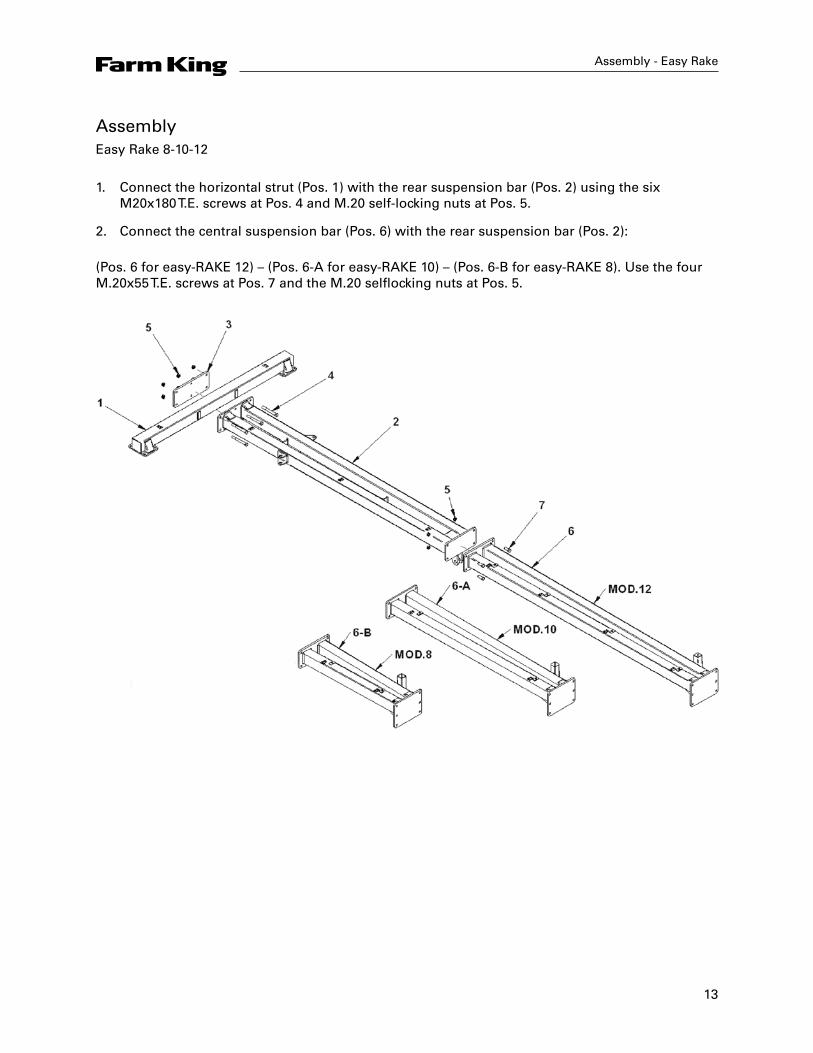
AssemblyEasy Rake 8-10-12
1. Connect the horizontal strut (Pos. 1) with the rear suspension bar (Pos. 2) using the six M20x180 T.E. screws at Pos. 4 and M.20 self-locking nuts at Pos. 5.
2. Connect the central suspension bar (Pos. 6) with the rear suspension bar (Pos. 2):
(Pos. 6 for easy-RAKE 12) – (Pos. 6-A for easy-RAKE 10) – (Pos. 6-B for easy-RAKE 8). Use the four M.20x55 T.E. screws at Pos. 7 and the M.20 selflocking nuts at Pos. 5.

14
Assembly - Easy Rake
Easy Rake 14
1. Connect the horizontal strut (Pos. 1) with the rear suspension bar (Pos. 2) using the six M20x180 T.E. screws at Pos. 4 and M.20 self-locking nuts at Pos. 5.
2. Connect the additional central suspension bar (Pos. 6) with the rear suspension bar (Pos. 2) using the four M20x55 T.E. screws at Pos. 7 and the M20 self-locking nuts at Pos. 5.
3. Connect the central suspension bar (Pos. 8) to the additional central suspension bar (Pos. 6) using the M20x55 T.E. screws at Pos. 7 and the M20 self-locking nuts at Pos. 5.
15
Assembly - Easy Rake
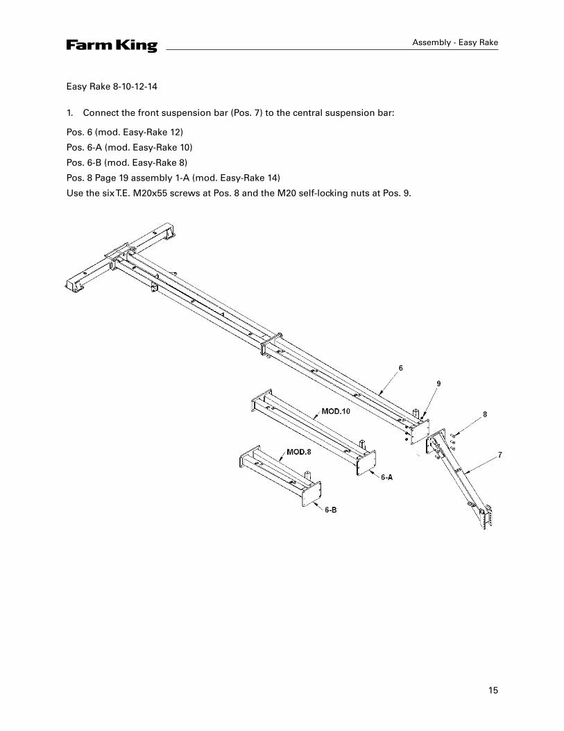
Easy Rake 8-10-12-14
1. Connect the front suspension bar (Pos. 7) to the central suspension bar:
Pos. 6 (mod. Easy-Rake 12)
Pos. 6-A (mod. Easy-Rake 10)
Pos. 6-B (mod. Easy-Rake 8)
Pos. 8 Page 19 assembly 1-A (mod. Easy-Rake 14)
Use the six T.E. M20x55 screws at Pos. 8 and the M20 self-locking nuts at Pos. 9.
16
Assembly - Easy Rake
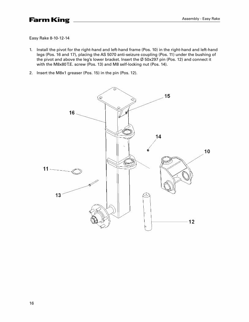
Easy Rake 8-10-12-14
1. Install the pivot for the right-hand and left-hand frame (Pos. 10) in the right-hand and left-hand legs (Pos. 16 and 17), placing the AS 5070 anti-seizure coupling (Pos. 11) under the bushing of the pivot and above the leg’s lower bracket. Insert the Ø 50x297 pin (Pos. 12) and connect it with the M8x80 T.E. screw (Pos. 13) and M8 self-locking nut (Pos. 14).
2. Insert the M8x1 greaser (Pos. 15) in the pin (Pos. 12).
17
Assembly - Easy Rake
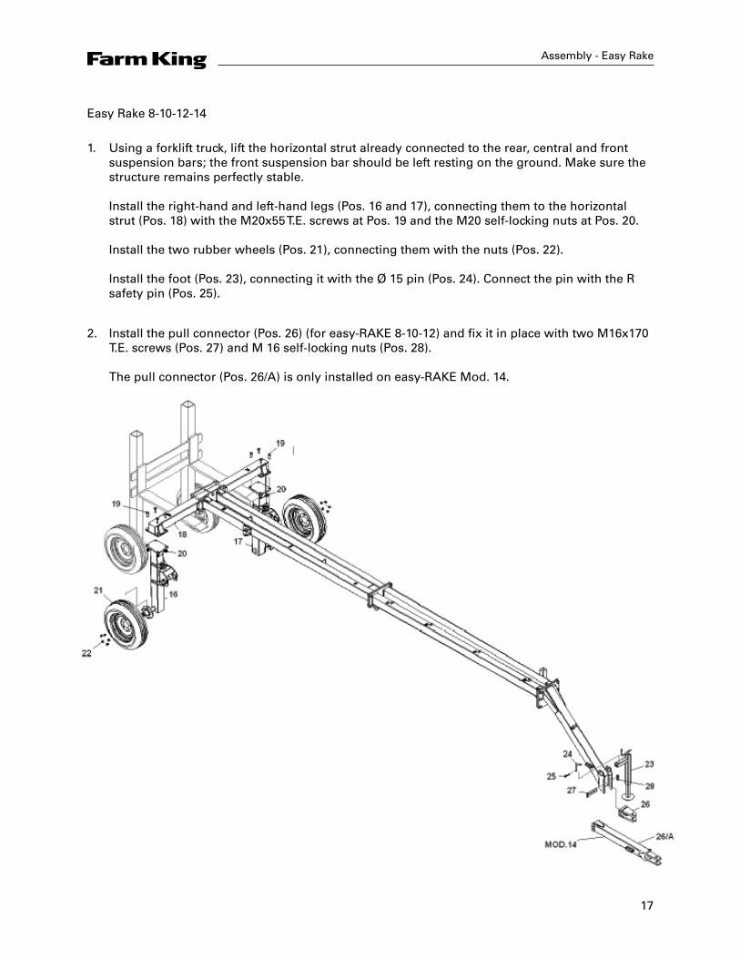
Easy Rake 8-10-12-14
1. Using a forklift truck, lift the horizontal strut already connected to the rear, central and front suspension bars; the front suspension bar should be left resting on the ground. Make sure the structure remains perfectly stable. Install the right-hand and left-hand legs (Pos. 16 and 17), connecting them to the horizontal strut (Pos. 18) with the M20x55 T.E. screws at Pos. 19 and the M20 self-locking nuts at Pos. 20. Install the two rubber wheels (Pos. 21), connecting them with the nuts (Pos. 22). Install the foot (Pos. 23), connecting it with the Ø 15 pin (Pos. 24). Connect the pin with the R safety pin (Pos. 25).
2. Install the pull connector (Pos. 26) (for easy-RAKE 8-10-12) and fix it in place with two M16x170 T.E. screws (Pos. 27) and M 16 self-locking nuts (Pos. 28). The pull connector (Pos. 26/A) is only installed on easy-RAKE Mod. 14.
18
Assembly - Easy Rake
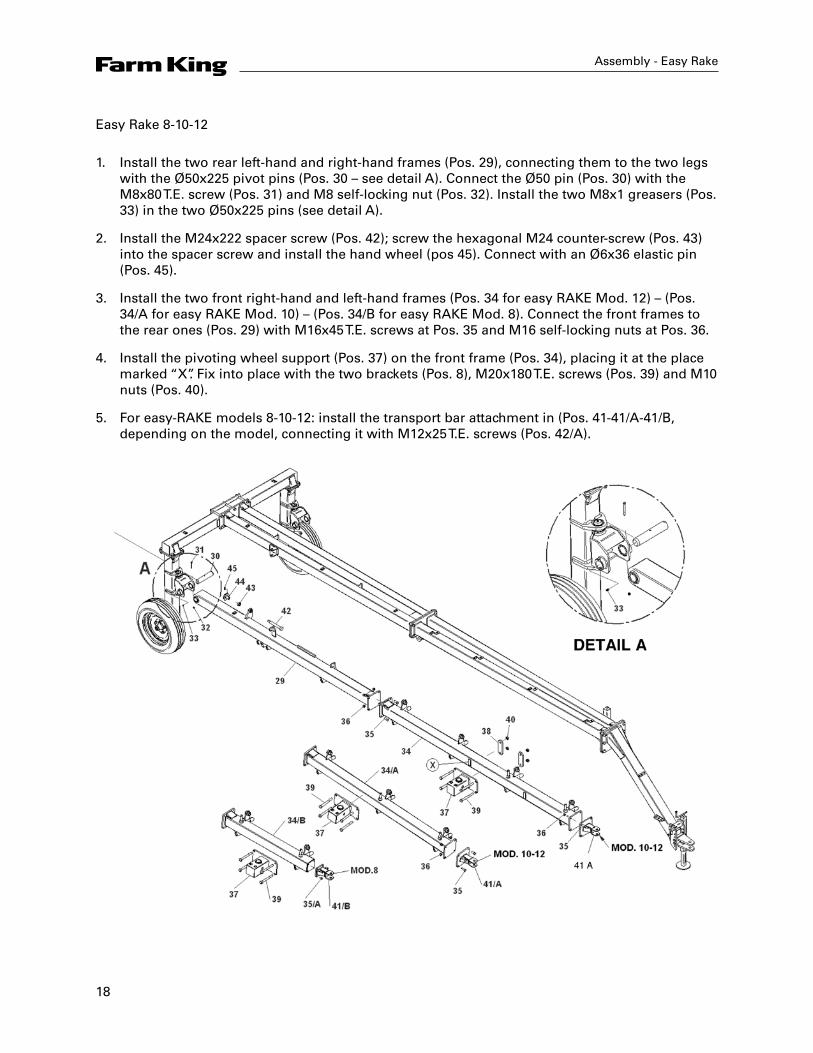
Easy Rake 8-10-12
1. Install the two rear left-hand and right-hand frames (Pos. 29), connecting them to the two legs with the Ø50x225 pivot pins (Pos. 30 – see detail A). Connect the Ø50 pin (Pos. 30) with the M8x80 T.E. screw (Pos. 31) and M8 self-locking nut (Pos. 32). Install the two M8x1 greasers (Pos. 33) in the two Ø50x225 pins (see detail A).
2. Install the M24x222 spacer screw (Pos. 42); screw the hexagonal M24 counter-screw (Pos. 43) into the spacer screw and install the hand wheel (pos 45). Connect with an Ø6x36 elastic pin (Pos. 45).
3. Install the two front right-hand and left-hand frames (Pos. 34 for easy RAKE Mod. 12) – (Pos. 34/A for easy RAKE Mod. 10) – (Pos. 34/B for easy RAKE Mod. 8). Connect the front frames to the rear ones (Pos. 29) with M16x45 T.E. screws at Pos. 35 and M16 self-locking nuts at Pos. 36.
4. Install the pivoting wheel support (Pos. 37) on the front frame (Pos. 34), placing it at the place marked “X”. Fix into place with the two brackets (Pos. 8), M20x180 T.E. screws (Pos. 39) and M10 nuts (Pos. 40).
5. For easy-RAKE models 8-10-12: install the transport bar attachment in (Pos. 41-41/A-41/B, depending on the model, connecting it with M12x25 T.E. screws (Pos. 42/A).

19
Assembly - Easy Rake
Easy Rake 14
1. Install the additional front right and left-hand parts of the frame (Pos. 41), connecting them to the front frame (Pos. 34) with 16x45 T.E. screws (Pos. 35) and M16 self-locking nuts (Pos. 36).
2. Install the front right and left wheel-supports (Pos. 46), connecting them to the additional front parts of the frame (Pos. 41) with four M16x45 T.E. screws (Pos. 35) and M16 self-locking nuts (Pos. 36).
3. Install the pivoting wheel support (Pos. 37) on the front frame, at the point marked Y. Connect with two 60x190x15 brackets, M20x180 T.E. screws (Pos. 39) and M20 self-locking nuts (Pos. 40).

20
Assembly - Easy Rake
Easy Rake 8-10-12
1. Insert the AS 50-70 coupling (Pos. 48) on the Ø50 pin (Pos. 47) of the pivoting wheel.
2. Install the two wheels with pivoting fork (Pos. 47) on the support (Pos. 37).
3. Install the disk brake (Pos. 49) and connect with 10x70 elastic pin (Pos. 50).
4. Connect the M12x100 T.E. screw (Pos. 51) to the connector boards (Pos. 52 and 53); connect the Ø38x56 spring (Pos. 54), Ø10x40 washer (Pos. 55) and the M12 self-locking nut (Pos. 56).
21
Assembly - Easy Rake
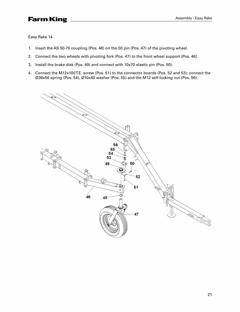
Easy Rake 14
1. Insert the AS 50-70 coupling (Pos. 48) on the 50 pin (Pos. 47) of the pivoting wheel.
2. Connect the two wheels with pivoting fork (Pos. 47) to the front wheel support (Pos. 46).
3. Install the brake disk (Pos. 49) and connect with 10x70 elastic pin (Pos. 50).
4. Connect the M12x100 T.E. screw (Pos. 51) to the connector boards (Pos. 52 and 53); connect the Ø38x56 spring (Pos. 54), Ø10x40 washer (Pos. 55) and the M12 self-locking nut (Pos. 56).
22
Assembly - Easy Rake
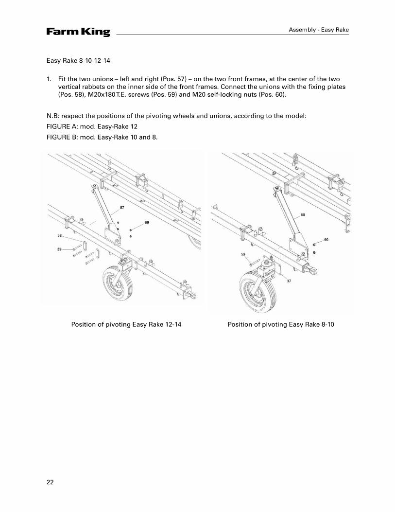
Easy Rake 8-10-12-14
1. Fit the two unions – left and right (Pos. 57) – on the two front frames, at the center of the two vertical rabbets on the inner side of the front frames. Connect the unions with the fixing plates (Pos. 58), M20x180 T.E. screws (Pos. 59) and M20 self-locking nuts (Pos. 60).
N.B: respect the positions of the pivoting wheels and unions, according to the model:
FIGURE A: mod. Easy-Rake 12
FIGURE B: mod. Easy-Rake 10 and 8.
Position of pivoting Easy Rake 12-14 Position of pivoting Easy Rake 8-10

23
Assembly - Easy Rake
Easy Rake 8-10-12-14
1. Install the hydraulic cylinder (Pos. 61) and connect it to the Ø30x100 pin (Pos. 62). Insert the hydraulic cylinder’s rod in the pin slide; connect with Ø27 washer (Pos. 64) and Ø8x50 elastic pin (Pos. 65).
24
Assembly - Easy Rake
Easy Rake 8-10-12-14
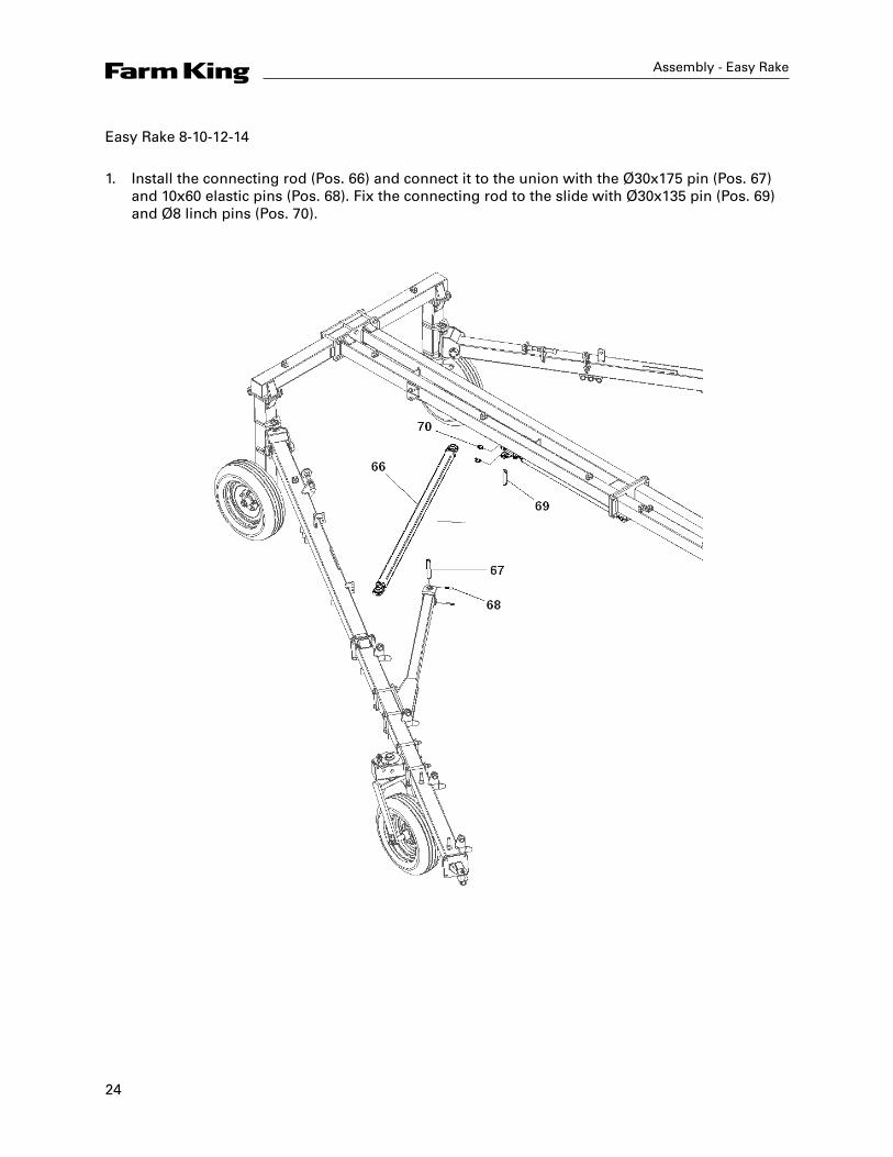
1. Install the connecting rod (Pos. 66) and connect it to the union with the Ø30x175 pin (Pos. 67) and 10x60 elastic pins (Pos. 68). Fix the connecting rod to the slide with Ø30x135 pin (Pos. 69) and Ø8 linch pins (Pos. 70).

25
Assembly - Easy Rake
Easy Rake 8-10-12-14
Star movement bars assembly
1. Assemble the hydraulic cylinder Pos. 79 and fix it in the frame with the pin Ø25x62 Pos. 80. Fix pin Ø25x62 Pos. 80 with spring pins Ø5x100 Pos. 115. Assemble the bushing/bar pin Pos. 71 A in the hydraulic cylinder rod Pos. 79 together with the two nylon bushings Pos. 114.
2. Assemble the rear bar Pos. 71, assemble the first mobile bar Pos. 72 and the first chain clamp Pos. 89. Insert the bar Pos. 71 into the bush/pin Pos. 71 A. Assemble the recall spring Ø40x5 Lg. 370 Pos. 71 B. Assemble the second bar passage Pos. 72 and the second chain clamp Pos. 89. Assemble the third bar passage and the third chain clamp. Fix the bar passages using T.E. M12x35 screws Pos. 73 and M12 nuts Pos. 74. Fixed to the supports Pos. 72 B. Fix the bar Pos. 71 in the bush/pin Pos. 71 B and fix using T.E. M8x50 screws Pos. 77 and M8 nuts Pos. 78.
N.B: the exact position of the chain clamps Pos. 89, must be in front of the mobile bar passages and positioned at a distance of 2" (50 mm) as indicated in figure C (star hydraulic cylinder raised Pos. 79 in closed position).
26
Assembly - Easy Rake
Easy Rake 14
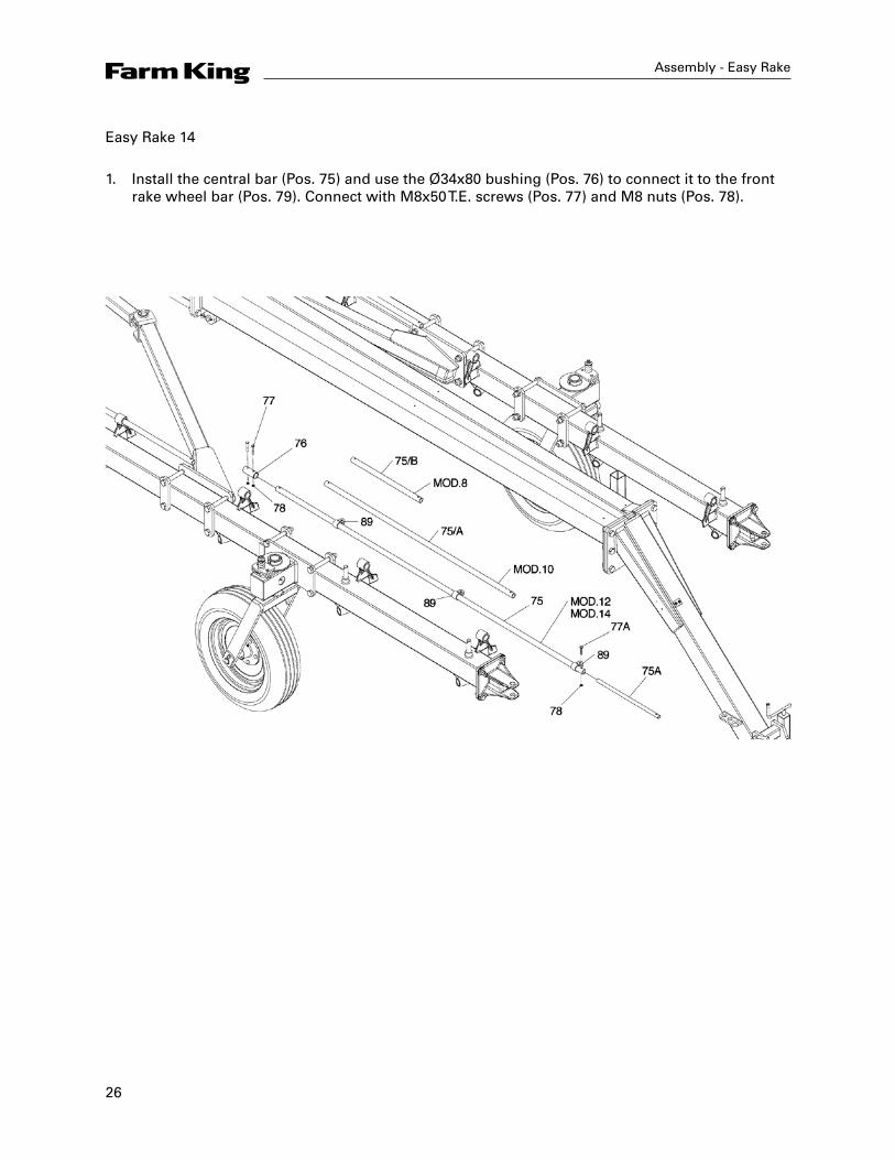
1. Install the central bar (Pos. 75) and use the Ø34x80 bushing (Pos. 76) to connect it to the front rake wheel bar (Pos. 79). Connect with M8x50 T.E. screws (Pos. 77) and M8 nuts (Pos. 78).
27
Assembly - Easy Rake
Easy Rake 8-10-12-14
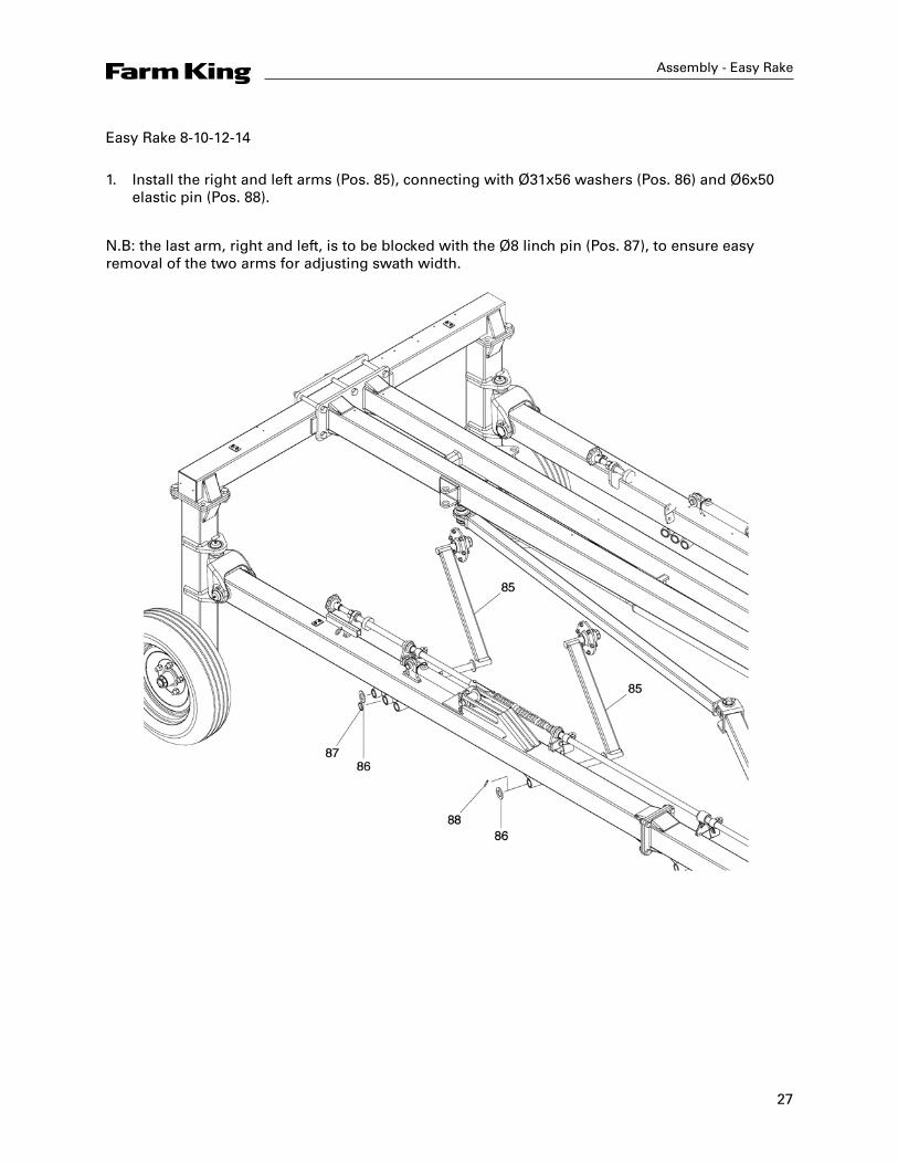
1. Install the right and left arms (Pos. 85), connecting with Ø31x56 washers (Pos. 86) and Ø6x50 elastic pin (Pos. 88).
N.B: the last arm, right and left, is to be blocked with the Ø8 linch pin (Pos. 87), to ensure easy removal of the two arms for adjusting swath width.
28
Assembly - Easy Rake
Easy Rake 8-10-12-14
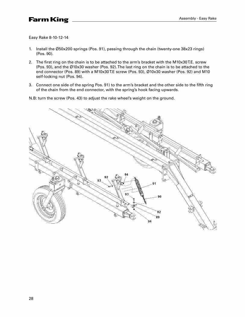
1. Install the Ø50x200 springs (Pos. 91), passing through the chain (twenty-one 38x23 rings) (Pos. 90).
2. The first ring on the chain is to be attached to the arm’s bracket with the M10x30 T.E. screw (Pos. 93), and the Ø10x30 washer (Pos. 92). The last ring on the chain is to be attached to the end connector (Pos. 89) with a M10x30 T.E screw (Pos. 93), Ø10x30 washer (Pos. 92) and M10 self-locking nut (Pos. 94).
3. Connect one side of the spring Pos. 91) to the arm’s bracket and the other side to the fifth ring of the chain from the end connector, with the spring’s hook facing upwards.
N.B: turn the screw (Pos. 43) to adjust the rake wheel’s weight on the ground.
29
Assembly - Easy Rake
Easy Rake 8-10-12-14
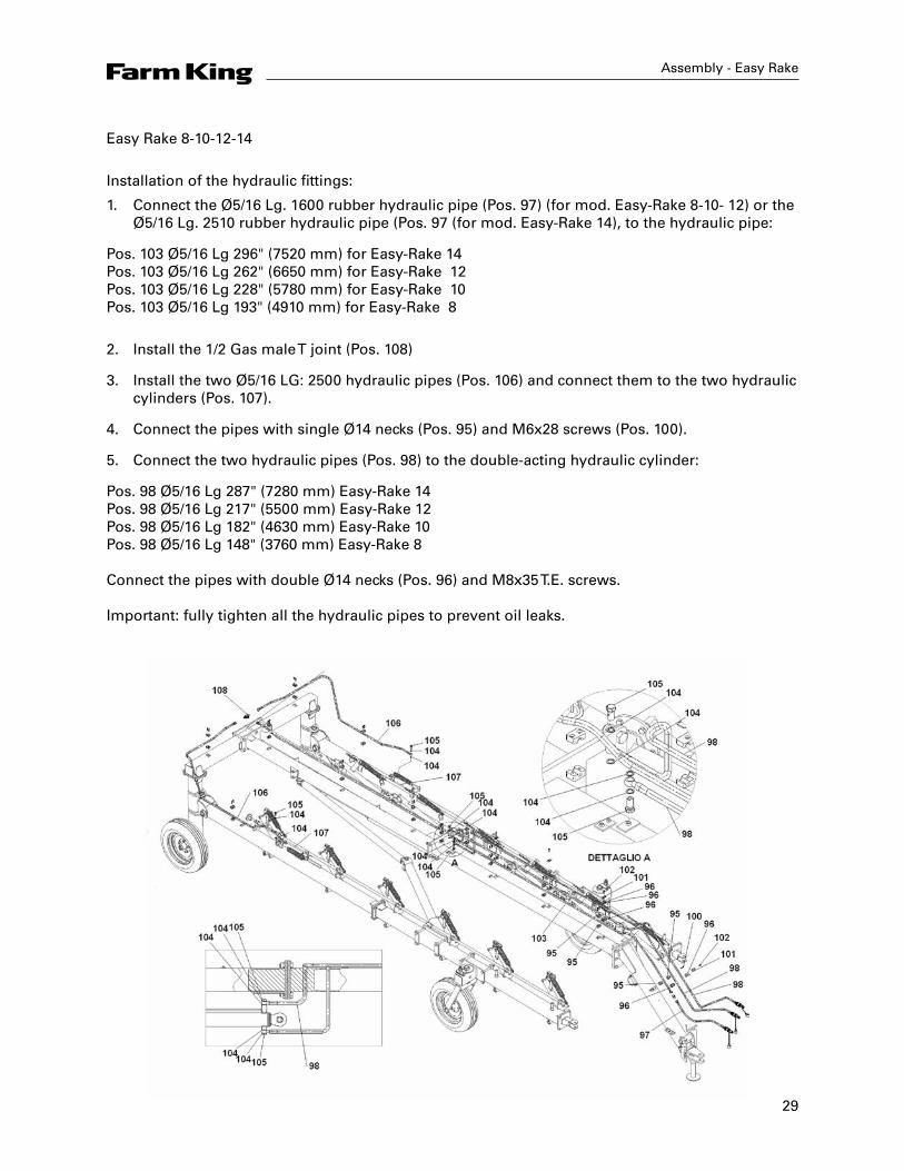
Installation of the hydraulic fittings:
1. Connect the Ø5/16 Lg. 1600 rubber hydraulic pipe (Pos. 97) (for mod. Easy-Rake 8-10- 12) or the Ø5/16 Lg. 2510 rubber hydraulic pipe (Pos. 97 (for mod. Easy-Rake 14), to the hydraulic pipe:
Pos. 103 Ø5/16 Lg 296" (7520 mm) for Easy-Rake 14 Pos. 103 Ø5/16 Lg 262" (6650 mm) for Easy-Rake 12 Pos. 103 Ø5/16 Lg 228" (5780 mm) for Easy-Rake 10 Pos. 103 Ø5/16 Lg 193" (4910 mm) for Easy-Rake 8
2. Install the 1/2 Gas male T joint (Pos. 108)
3. Install the two Ø5/16 LG: 2500 hydraulic pipes (Pos. 106) and connect them to the two hydraulic cylinders (Pos. 107).
4. Connect the pipes with single Ø14 necks (Pos. 95) and M6x28 screws (Pos. 100).
5. Connect the two hydraulic pipes (Pos. 98) to the double-acting hydraulic cylinder:
Pos. 98 Ø5/16 Lg 287" (7280 mm) Easy-Rake 14 Pos. 98 Ø5/16 Lg 217" (5500 mm) Easy-Rake 12 Pos. 98 Ø5/16 Lg 182" (4630 mm) Easy-Rake 10 Pos. 98 Ø5/16 Lg 148" (3760 mm) Easy-Rake 8 Connect the pipes with double Ø14 necks (Pos. 96) and M8x35 T.E. screws. Important: fully tighten all the hydraulic pipes to prevent oil leaks.
30
Assembly - Easy Rake
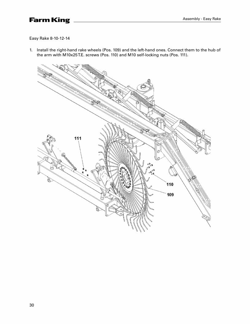
Easy Rake 8-10-12-14
1. Install the right-hand rake wheels (Pos. 109) and the left-hand ones. Connect them to the hub of the arm with M10x25 T.E. screws (Pos. 110) and M10 self-locking nuts (Pos. 111).
31
Assembly - Easy Rake
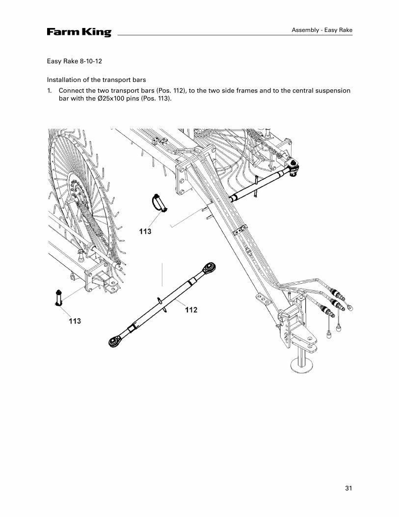
Easy Rake 8-10-12
Installation of the transport bars
1. Connect the two transport bars (Pos. 112), to the two side frames and to the central suspension bar with the Ø25x100 pins (Pos. 113).
32
Assembly - Easy Rake
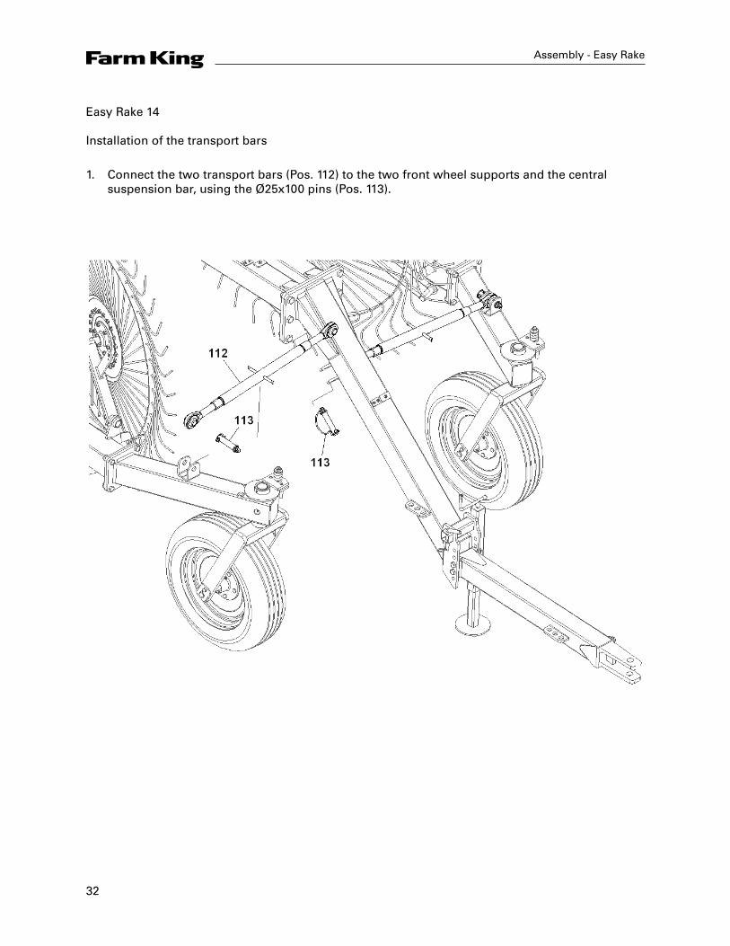
Easy Rake 14 Installation of the transport bars
1. Connect the two transport bars (Pos. 112) to the two front wheel supports and the central suspension bar, using the Ø25x100 pins (Pos. 113).
33
Assembly - Easy Rake
Assembly of Central Rake Wheels (Optional)
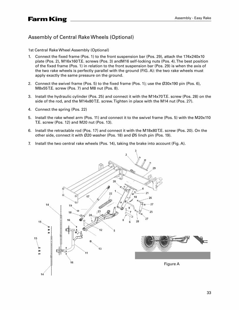
1st Central Rake Wheel Assembly (Optional)
1. Connect the fixed frame (Pos. 1) to the front suspension bar (Pos. 29), attach the 174x240x10 plate (Pos. 2), M16x160 T.E. screws (Pos. 3) andM16 self-locking nuts (Pos. 4). The best position of the fixed frame (Pos. 1) in relation to the front suspension bar (Pos. 29) is when the axis of the two rake wheels is perfectly parallel with the ground (FIG. A): the two rake wheels must apply exactly the same pressure on the ground.
2. Connect the swivel frame (Pos. 5) to the fixed frame (Pos. 1); use the Ø30x190 pin (Pos. 6), M8x55 T.E. screw (Pos. 7) and M8 nut (Pos. 8).
3. Install the hydraulic cylinder (Pos. 25) and connect it with the M14x70 T.E. screw (Pos. 28) on the side of the rod, and the M14x80 T.E. screw. Tighten in place with the M14 nut (Pos. 27).
4. Connect the spring (Pos. 22)
5. Install the rake wheel arm (Pos. 11) and connect it to the swivel frame (Pos. 5) with the M20x110 T.E. screw (Pos. 12) and M20 nut (Pos. 13).
6. Install the retractable rod (Pos. 17) and connect it with the M18x80 T.E. screw (Pos. 20). On the other side, connect it with Ø20 washer (Pos. 18) and Ø5 linch pin (Pos. 19).
7. Install the two central rake wheels (Pos. 14), taking the brake into account (Fig. A).
Figure A
34
Assembly - Easy Rake
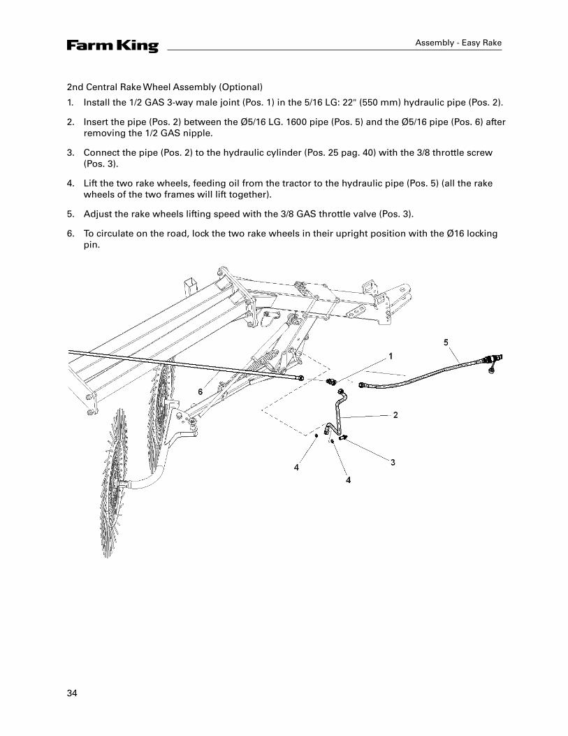
2nd Central Rake Wheel Assembly (Optional)
1. Install the 1/2 GAS 3-way male joint (Pos. 1) in the 5/16 LG: 22" (550 mm) hydraulic pipe (Pos. 2).
2. Insert the pipe (Pos. 2) between the Ø5/16 LG. 1600 pipe (Pos. 5) and the Ø5/16 pipe (Pos. 6) after removing the 1/2 GAS nipple.
3. Connect the pipe (Pos. 2) to the hydraulic cylinder (Pos. 25 pag. 40) with the 3/8 throttle screw (Pos. 3).
4. Lift the two rake wheels, feeding oil from the tractor to the hydraulic pipe (Pos. 5) (all the rake wheels of the two frames will lift together).
5. Adjust the rake wheels lifting speed with the 3/8 GAS throttle valve (Pos. 3).
6. To circulate on the road, lock the two rake wheels in their upright position with the Ø16 locking pin.
35
Operation - Easy Rake
Operation Instructions
Preliminary InformationSuitable and optimal use of the rake not only helps avoid accidents but is also the only way to ensure high yield and make use of the rakes full potential and performance. The rake must be used by trained adult personnel knowledgeable of the instructions in this manual and on the labels. Safety is of paramount importance for the personnel that operate, repair and maintain the equipment. As the instructions given cannot possibly cover all possible working situations, personnel must always exercise caution and common sense. Before the tractor can transport the rake to the work area, it is advisable to carry out the following preliminary checks:
• Ensure all the parts of the rake are in their intended position and are securely fitted;• Ensure the rake is fitted properly to the tractor;• Check efficiency of all the protection devices;• Carry out the daily maintenance checks described in the relative paragraph. Note: should
the rake be returned to service after a long period of inactivity, ensure it has been properly maintained and that it has not been damaged in any way by poor weather or storage conditions.
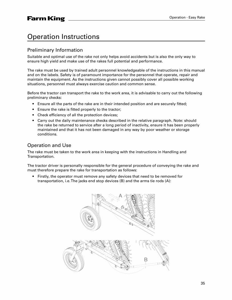
Operation and UseThe rake must be taken to the work area in keeping with the instructions in Handling and Transportation. The tractor driver is personally responsible for the general procedure of conveying the rake and must therefore prepare the rake for transportation as follows:
• Firstly, the operator must remove any safety devices that need to be removed for transportation, i.e. The jacks end stop devices (B) and the arms tie rods (A):
B
A
36
Operation - Easy Rake
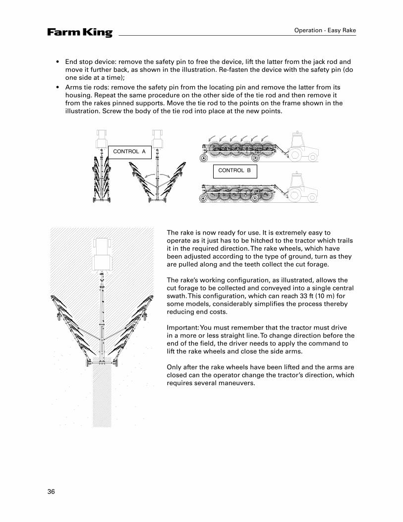
• End stop device: remove the safety pin to free the device, lift the latter from the jack rod and move it further back, as shown in the illustration. Re-fasten the device with the safety pin (do one side at a time);
• Arms tie rods: remove the safety pin from the locating pin and remove the latter from its housing. Repeat the same procedure on the other side of the tie rod and then remove it from the rakes pinned supports. Move the tie rod to the points on the frame shown in the illustration. Screw the body of the tie rod into place at the new points.
CONTROL A
CONTROL B
The rake is now ready for use. It is extremely easy to operate as it just has to be hitched to the tractor which trails it in the required direction. The rake wheels, which have been adjusted according to the type of ground, turn as they are pulled along and the teeth collect the cut forage. The rake’s working configuration, as illustrated, allows the cut forage to be collected and conveyed into a single central swath. This configuration, which can reach 33 ft (10 m) for some models, considerably simplifies the process thereby reducing end costs. Important: You must remember that the tractor must drive in a more or less straight line. To change direction before the end of the field, the driver needs to apply the command to lift the rake wheels and close the side arms. Only after the rake wheels have been lifted and the arms are closed can the operator change the tractor’s direction, which requires several maneuvers.
37
Operation - Easy Rake
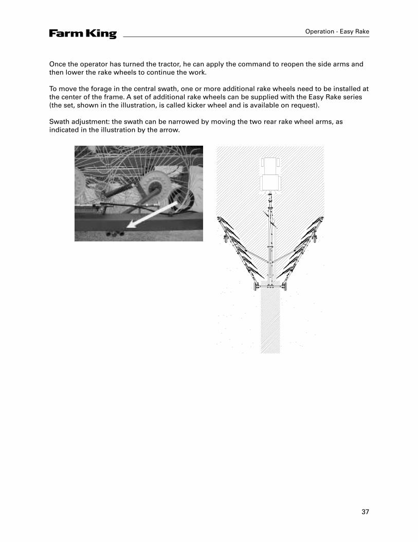
Once the operator has turned the tractor, he can apply the command to reopen the side arms and then lower the rake wheels to continue the work. To move the forage in the central swath, one or more additional rake wheels need to be installed at the center of the frame. A set of additional rake wheels can be supplied with the Easy Rake series (the set, shown in the illustration, is called kicker wheel and is available on request). Swath adjustment: the swath can be narrowed by moving the two rear rake wheel arms, as indicated in the illustration by the arrow.
38
Operation - Easy Rake
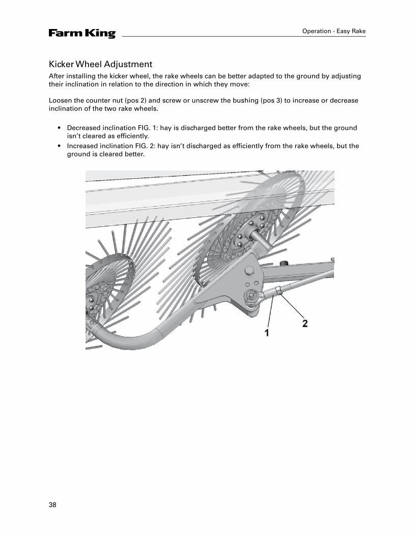
Kicker Wheel AdjustmentAfter installing the kicker wheel, the rake wheels can be better adapted to the ground by adjusting their inclination in relation to the direction in which they move: Loosen the counter nut (pos 2) and screw or unscrew the bushing (pos 3) to increase or decrease inclination of the two rake wheels.
• Decreased inclination FIG. 1: hay is discharged better from the rake wheels, but the ground isn’t cleared as efficiently.
• Increased inclination FIG. 2: hay isn’t discharged as efficiently from the rake wheels, but the ground is cleared better.

39
Operation - Easy Rake
Prior to work breaks (even short ones) the operator must always:
• Switch off the tractor’s engine• Apply the parking brake• Place the gear stick in neutral• Remove the keys from the ignition;
When the operator has finished work for the day, he must place the rake back in its transportation configuration before returning the tractor to its parking area.
40
Parts - Easy Rake
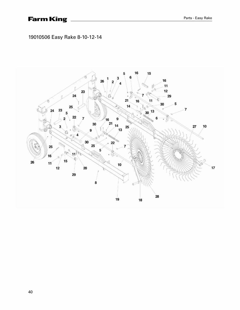
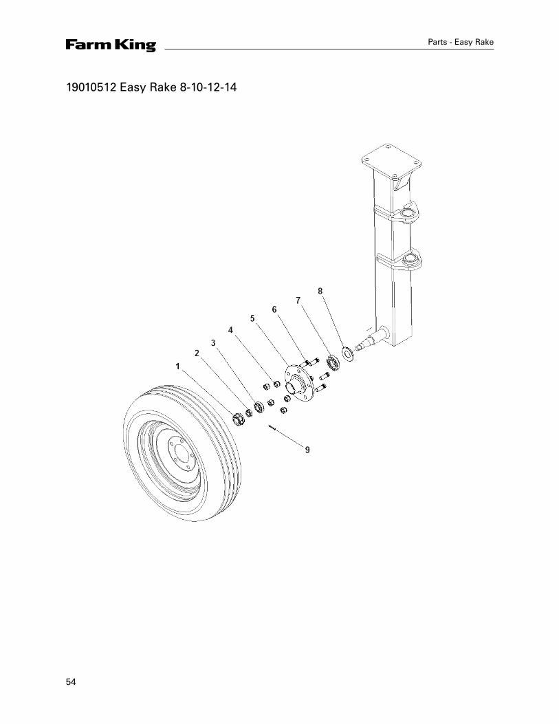
19010506 Easy Rake 8-10-12-14
41
Parts - Easy Rake
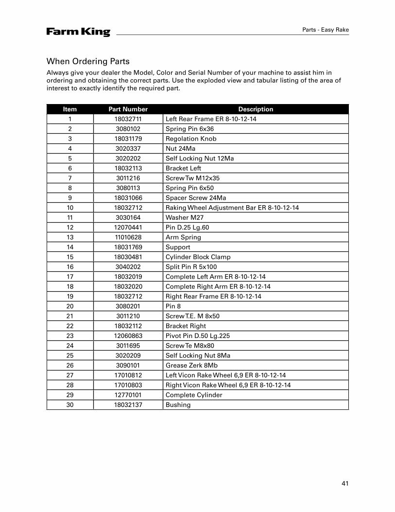
When Ordering PartsAlways give your dealer the Model, Color and Serial Number of your machine to assist him in ordering and obtaining the correct parts. Use the exploded view and tabular listing of the area of interest to exactly identify the required part.
Item Part Number Description
1 18032711 Left Rear Frame ER 8-10-12-14
2 3080102 Spring Pin 6x36
3 18031179 Regolation Knob
4 3020337 Nut 24Ma
5 3020202 Self Locking Nut 12Ma
6 18032113 Bracket Left
7 3011216 Screw Tw M12x35
8 3080113 Spring Pin 6x50
9 18031066 Spacer Screw 24Ma
10 18032712 Raking Wheel Adjustment Bar ER 8-10-12-14
11 3030164 Washer M27
12 12070441 Pin D.25 Lg.60
13 11010628 Arm Spring
14 18031769 Support
15 18030481 Cylinder Block Clamp
16 3040202 Split Pin R 5x100
17 18032019 Complete Left Arm ER 8-10-12-14
18 18032020 Complete Right Arm ER 8-10-12-14
19 18032712 Right Rear Frame ER 8-10-12-14
20 3080201 Pin 8
21 3011210 Screw T.E. M 8x50
22 18032112 Bracket Right
23 12060863 Pivot Pin D.50 Lg.225
24 3011695 Screw Te M8x80
25 3020209 Self Locking Nut 8Ma
26 3090101 Grease Zerk 8Mb
27 17010812 Left Vicon Rake Wheel 6,9 ER 8-10-12-14
28 17010803 Right Vicon Rake Wheel 6,9 ER 8-10-12-14
29 12770101 Complete Cylinder
30 18032137 Bushing
42
Parts - Easy Rake
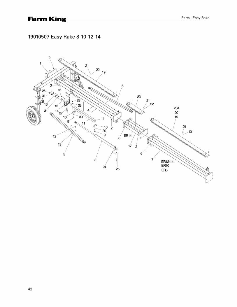
19010507 Easy Rake 8-10-12-14

43
Item Part Number Description
1 18032022 Fastening Plate
2 3020216 Self Locking Nut 20Ma
3 3011648 Screw Te 20x180
4 18032023 Pull Bar E.R. 8-10-12-14
5 18032024 Connecting Bar
6 3011694 Screw Te M20x55
7 18032025 Central Drawbar ER 8 - ER 10 Autosteer
7A 18032026 Central Drawbar ER 10 - ER 12 Autosteer
7B 18032027 Central Drawbar ER 12-14 - ER 14 Autosteer
8 12770131 Hydraulic Cylinder
9 3011271 Screw Te M16x70
10 18032028 Support
11 12880417 Skid Shaft
12 3030164 Washer 27
13 3080105 Spring Pin 8-50
14 18032713 Pin
15 12060868 Pin 30-135
16 12880614 Pin 8
17 18032074 Extension Frame ER 14
18 18032730 Bushing
19 18031757 Hydraulic Hose Carter ER 8-10-12-14
20 18031758 Hydraulic Hose Carter ER 10
20A 18031759 Hydraulic Hose Carter ER 8
21 3011290 Screw Te M6x10
22 3030158 Washer M6
23 18031760 Hydraulic Hose Carter Er 12
24 12060802 Pin Ø30 L.98
25 3080113 Spring Pin 6x50
26 3120111 Seeger Ring I 52
27 18032708 Pin For Skid
28 3030222 Self Locking Nut M 22
29 3030176 Washer M 22
30 3030322 Grower Washer D. 16
31 10010714 Scraper Wrm 157188
Parts - Easy Rake
44
Parts - Easy Rake
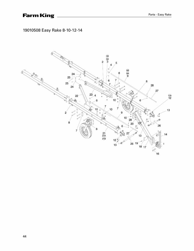
19010508 Easy Rake 8-10-12-14

45
Parts - Easy Rake
Item Part Number Description
1 3020204 Self Locking Nut 16Ma
2 3011645 Screw Te M16x45
3 18032030 Left Front Frame Er 8
3A 18032031 Left Front Frame Er 10
3B 18032062 Left Front Frame Er 12-14
4 3011210 Screw Te M8x50
5 18030435 Bush D.33,7 Lg.80
6 3020209 Self Locking Nut 8Ma
7 18032033 Elbow Arm Attachment Brackets
8 3011648 Screw Te M20x180
9 18032034 Raking Wheel Adjustment Bar ER 8 Lg.500
9A 18032035 Raking Wheel Adjustment Bar ER 10 Lg.1370
9B 18032036 Raking Wheel Adjustment Bar ER 12-14 Lg.2240
10 3020216 Self Locking Nut 20Ma
11 18032037 Transport Bar Support ER 8
11A 18032038 Transport Bar Support ER 0-12
12 3011255 Screw Te M12x25 For ER 8
12A 3011645 Screw Te M16x45 For ER 10-12
13 12310306 Clip Pin
14 18032039 Jack
15 18032040 Pull Linkage Attachment
16 3010308 Screw Te M16x170
17 18032064 Front Drawbar
18 12120104 Pin 15x200
19 3040202 Split Pin R 5x100
20 3011694 Screw Te M20x55
21 18032042 Right Front Frame ER 8
21A 18032043 Right Front Frame ER 10
21B 18032063 Right Front Frame ER 12-14
22 18032045 Right Frame Elbow Arm
23 18032046 Left Frame Elbow Arm
24 12060866 Pin 30x175
25 3080107 Spring Pin 10X60
26 12310702 Transport Bar
27 18032716 Reinforcement
28 3011619 Screw T.E. M 8x40
46
Parts - Easy Rake
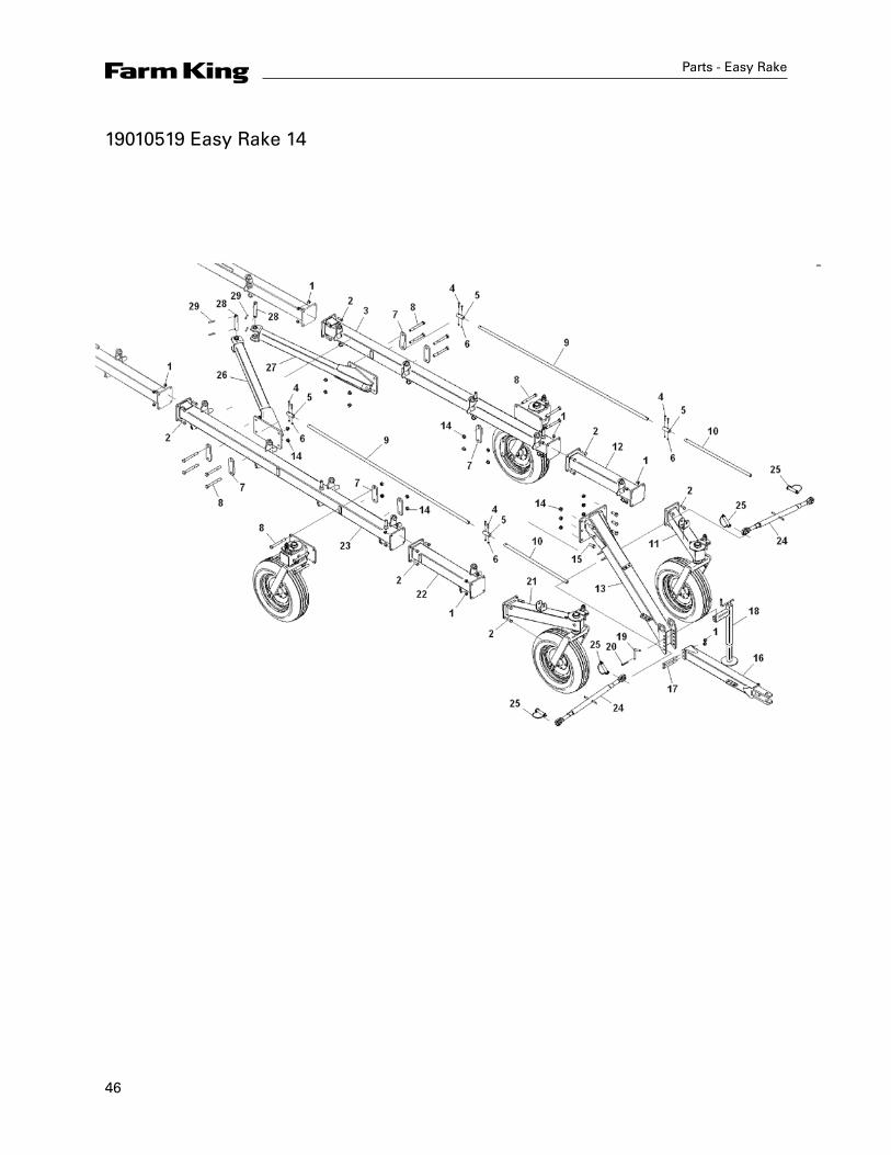
19010519 Easy Rake 14

47
Parts - Easy Rake
Item Part Number Description
1 3020204 Self Locking Nut 16Ma
2 3011645 Screw Te M16x45
3 18032062 Left Front Frame ER 12-14
4 3011210 Screw Te M8x50
5 18030435 Bush D.33,7 Lg.80
6 3020209 Self Locking Nut 8Ma
7 18032033 Elbow Arm Attachment Brackets
8 3011648 Screw Te M20x180
9 18032036 Raking Wheel Adjustment Bar ER 12-14 Lg.2240
10 18032075 Raking Wheel Adjustment Bar ER 14 Lg.870
11 18032076 Left Ground Wheel Support
12 18032077 Left Extension Frame ER 14
13 18032064 Front Drawbar
14 3020216 Self Locking Nut 20Ma
15 3011694 Screw Te M20x55
16 18032078 Pull Bar Linkage
17 3010308 Screw Te M16x170
18 18032039 Jack
19 12120104 Pin 15x200
20 3040202 Split Pin R 5x100
21 18032079 Right Ground Wheel Support
22 18032080 Extension Frame ER 14
23 18032063 Right Front Frame ER 12-14
24 12310702 Transport Bar
25 12310306 Clip Pin
48
Parts - Easy Rake
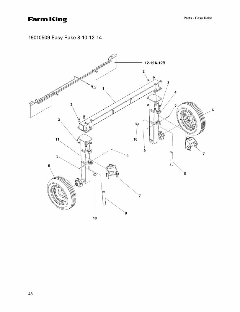
19010509 Easy Rake 8-10-12-14
49
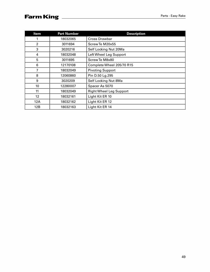
Parts - Easy Rake
Item Part Number Description
1 18032065 Cross Drawbar
2 3011694 Screw Te M20x55
3 3020216 Self Locking Nut 20Ma
4 18032048 Left Wheel Leg Support
5 3011695 Screw Te M8x80
6 12170108 Complete Wheel 205/70 R15
7 18032049 Pivoting Support
8 12060860 Pin D.50 Lg.295
9 3020209 Self Locking Nut 8Ma
10 12280007 Spacer As 5070
11 18032049 Right Wheel Leg Support
12 18032161 Light Kit ER 10
12A 18032162 Light Kit ER 12
12B 18032163 Light Kit ER 14

50
Parts - Easy Rake
19010510 Easy Rake 8-10-12-14
51
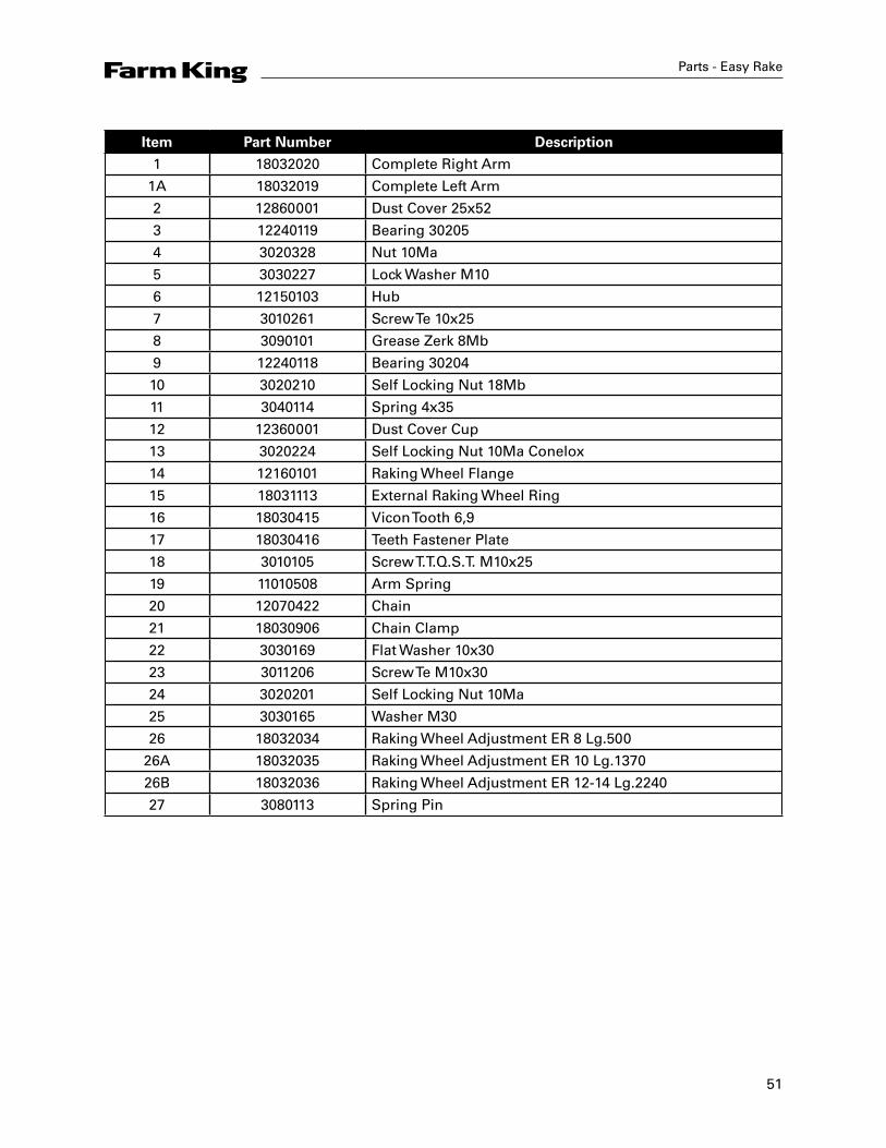
Parts - Easy Rake
Item Part Number Description
1 18032020 Complete Right Arm
1A 18032019 Complete Left Arm
2 12860001 Dust Cover 25x52
3 12240119 Bearing 30205
4 3020328 Nut 10Ma
5 3030227 Lock Washer M10
6 12150103 Hub
7 3010261 Screw Te 10x25
8 3090101 Grease Zerk 8Mb
9 12240118 Bearing 30204
10 3020210 Self Locking Nut 18Mb
11 3040114 Spring 4x35
12 12360001 Dust Cover Cup
13 3020224 Self Locking Nut 10Ma Conelox
14 12160101 Raking Wheel Flange
15 18031113 External Raking Wheel Ring
16 18030415 Vicon Tooth 6,9
17 18030416 Teeth Fastener Plate
18 3010105 Screw T.T.Q.S.T. M10x25
19 11010508 Arm Spring
20 12070422 Chain
21 18030906 Chain Clamp
22 3030169 Flat Washer 10x30
23 3011206 Screw Te M10x30
24 3020201 Self Locking Nut 10Ma
25 3030165 Washer M30
26 18032034 Raking Wheel Adjustment ER 8 Lg.500
26A 18032035 Raking Wheel Adjustment ER 10 Lg.1370
26B 18032036 Raking Wheel Adjustment ER 12-14 Lg.2240
27 3080113 Spring Pin
52
Parts - Easy Rake
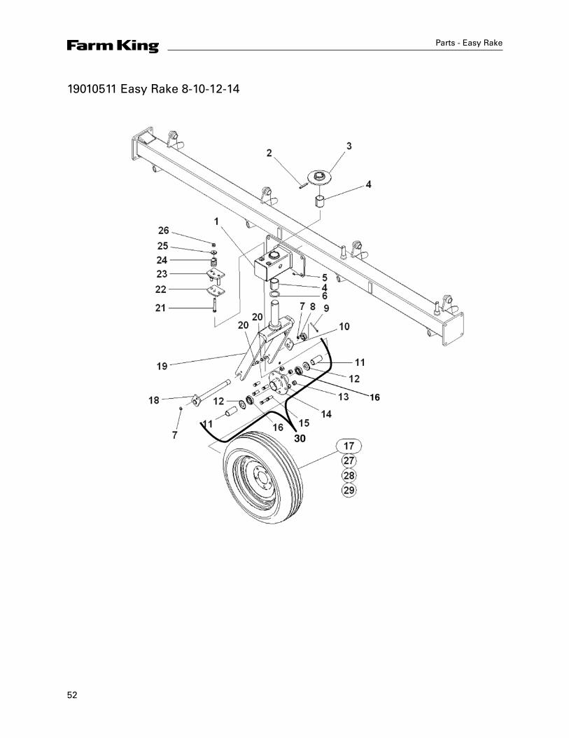
19010511 Easy Rake 8-10-12-14
53
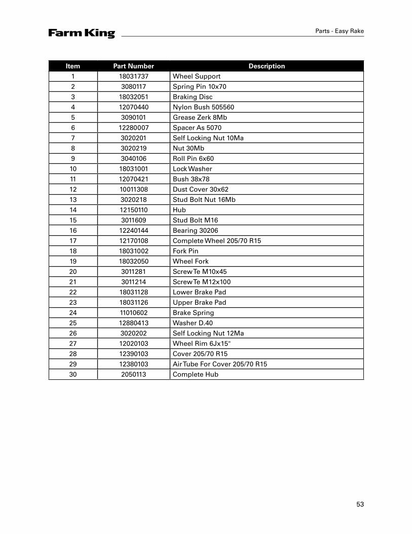
Parts - Easy Rake
Item Part Number Description
1 18031737 Wheel Support
2 3080117 Spring Pin 10x70
3 18032051 Braking Disc
4 12070440 Nylon Bush 505560
5 3090101 Grease Zerk 8Mb
6 12280007 Spacer As 5070
7 3020201 Self Locking Nut 10Ma
8 3020219 Nut 30Mb
9 3040106 Roll Pin 6x60
10 18031001 Lock Washer
11 12070421 Bush 38x78
12 10011308 Dust Cover 30x62
13 3020218 Stud Bolt Nut 16Mb
14 12150110 Hub
15 3011609 Stud Bolt M16
16 12240144 Bearing 30206
17 12170108 Complete Wheel 205/70 R15
18 18031002 Fork Pin
19 18032050 Wheel Fork
20 3011281 Screw Te M10x45
21 3011214 Screw Te M12x100
22 18031128 Lower Brake Pad
23 18031126 Upper Brake Pad
24 11010602 Brake Spring
25 12880413 Washer D.40
26 3020202 Self Locking Nut 12Ma
27 12020103 Wheel Rim 6Jx15"
28 12390103 Cover 205/70 R15
29 12380103 Air Tube For Cover 205/70 R15
30 2050113 Complete Hub
54
Parts - Easy Rake
19010512 Easy Rake 8-10-12-14
55
Parts - Easy Rake
Item Part Number Description
1 12360003 Dust Cover Cap
2 3020217 Self Locking Nut 20Mb
3 12240119 Bearing 30205
4 3020218 Stud Bolt 16Mb
5 12150108 Hub
6 3011609 Stud Bolt M16
7 12240143 Bearing 30207
8 12360002 Dust Cover 35x72
9 3040114 Spring Pin 4x35
56
Parts - Easy Rake
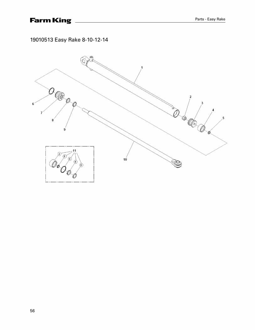
19010513 Easy Rake 8-10-12-14

57
Parts - Easy Rake
Item Part Number Description
1 12770135 Cylinder
2 3020217 Self Locking Nut 20Mb
3 12770216 Piston 0706020
4 Sela Dbm 236173
5 O-Ring 8-125
6 O-Ring 8-156
7 12420104 Guide
8 Balsele
9 Scraper Ring Wrm 118149
10 12440102 Shaft D.35
11 10010699 Seal Kit For Cylinder Code 12770131
58
Parts - Easy Rake
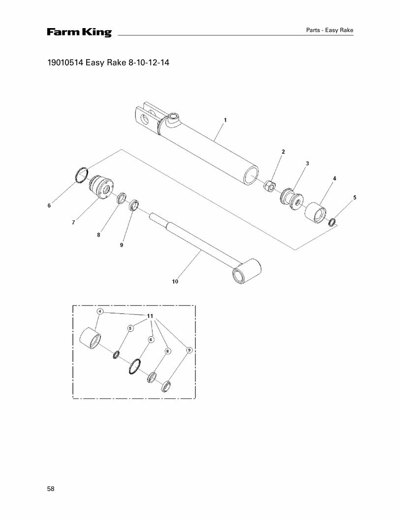
19010514 Easy Rake 8-10-12-14
59
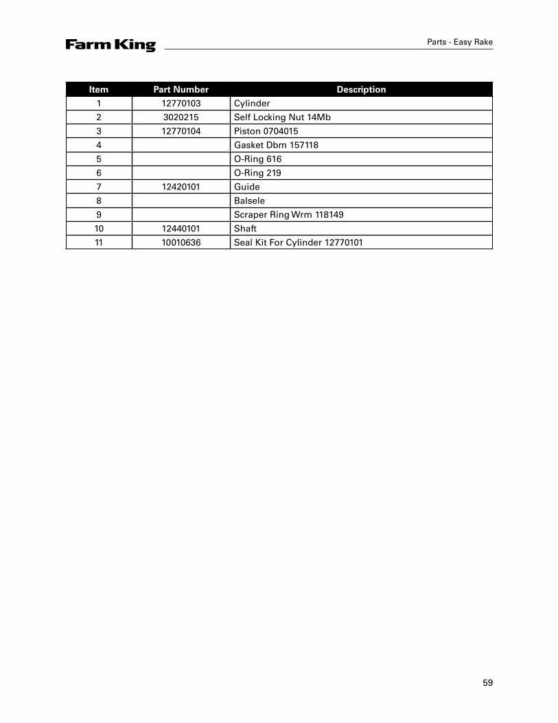
Parts - Easy Rake
Item Part Number Description
1 12770103 Cylinder
2 3020215 Self Locking Nut 14Mb
3 12770104 Piston 0704015
4 Gasket Dbm 157118
5 O-Ring 616
6 O-Ring 219
7 12420101 Guide
8 Balsele
9 Scraper Ring Wrm 118149
10 12440101 Shaft
11 10010636 Seal Kit For Cylinder 12770101
60
Parts - Easy Rake
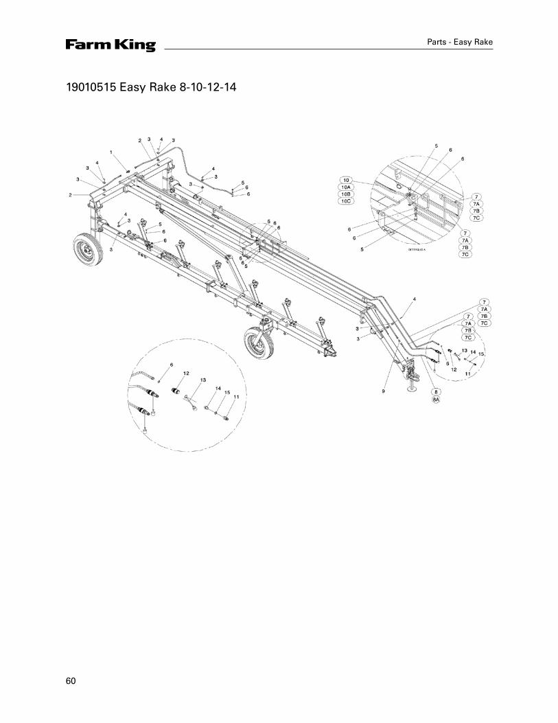
19010515 Easy Rake 8-10-12-14
61
Parts - Easy Rake
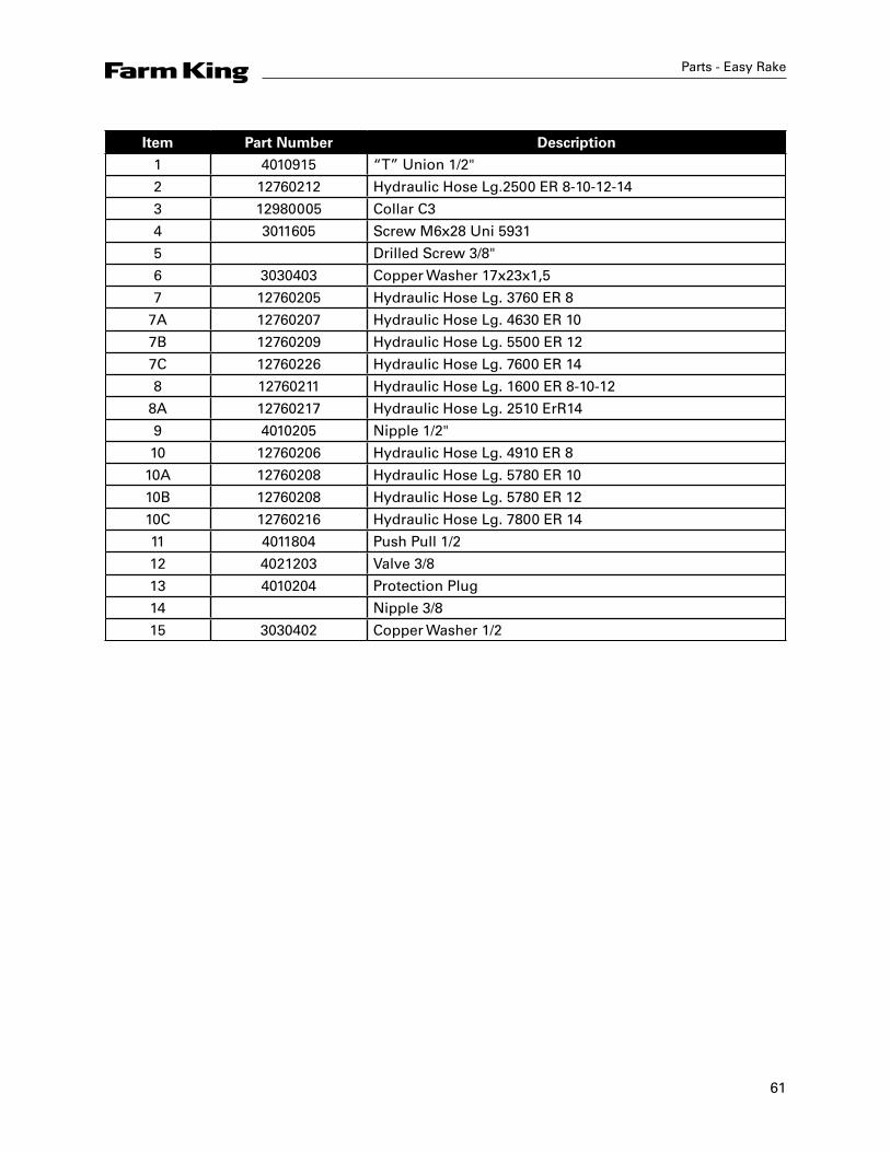
Item Part Number Description
1 4010915 “T” Union 1/2"
2 12760212 Hydraulic Hose Lg.2500 ER 8-10-12-14
3 12980005 Collar C3
4 3011605 Screw M6x28 Uni 5931
5 Drilled Screw 3/8"
6 3030403 Copper Washer 17x23x1,5
7 12760205 Hydraulic Hose Lg. 3760 ER 8
7A 12760207 Hydraulic Hose Lg. 4630 ER 10
7B 12760209 Hydraulic Hose Lg. 5500 ER 12
7C 12760226 Hydraulic Hose Lg. 7600 ER 14
8 12760211 Hydraulic Hose Lg. 1600 ER 8-10-12
8A 12760217 Hydraulic Hose Lg. 2510 ErR14
9 4010205 Nipple 1/2"
10 12760206 Hydraulic Hose Lg. 4910 ER 8
10A 12760208 Hydraulic Hose Lg. 5780 ER 10
10B 12760208 Hydraulic Hose Lg. 5780 ER 12
10C 12760216 Hydraulic Hose Lg. 7800 ER 14
11 4011804 Push Pull 1/2
12 4021203 Valve 3/8
13 4010204 Protection Plug
14 Nipple 3/8
15 3030402 Copper Washer 1/2
62
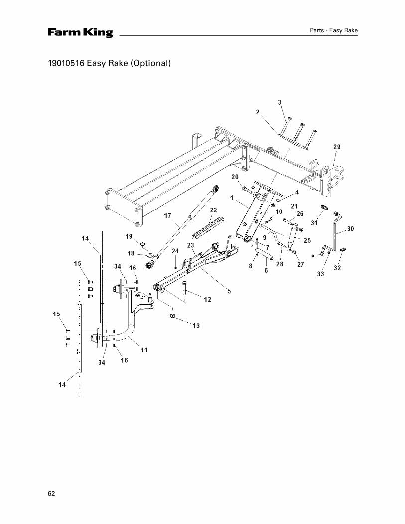
19010516 Easy Rake (Optional)
Parts - Easy Rake
63
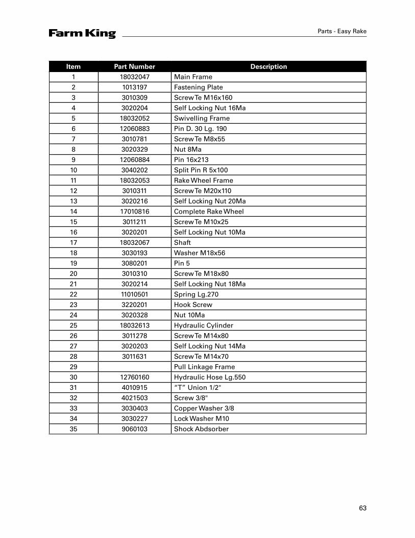
Item Part Number Description
1 18032047 Main Frame
2 1013197 Fastening Plate
3 3010309 Screw Te M16x160
4 3020204 Self Locking Nut 16Ma
5 18032052 Swivelling Frame
6 12060883 Pin D. 30 Lg. 190
7 3010781 Screw Te M8x55
8 3020329 Nut 8Ma
9 12060884 Pin 16x213
10 3040202 Split Pin R 5x100
11 18032053 Rake Wheel Frame
12 3010311 Screw Te M20x110
13 3020216 Self Locking Nut 20Ma
14 17010816 Complete Rake Wheel
15 3011211 Screw Te M10x25
16 3020201 Self Locking Nut 10Ma
17 18032067 Shaft
18 3030193 Washer M18x56
19 3080201 Pin 5
20 3010310 Screw Te M18x80
21 3020214 Self Locking Nut 18Ma
22 11010501 Spring Lg.270
23 3220201 Hook Screw
24 3020328 Nut 10Ma
25 18032613 Hydraulic Cylinder
26 3011278 Screw Te M14x80
27 3020203 Self Locking Nut 14Ma
28 3011631 Screw Te M14x70
29 Pull Linkage Frame
30 12760160 Hydraulic Hose Lg.550
31 4010915 “T” Union 1/2"
32 4021503 Screw 3/8"
33 3030403 Copper Washer 3/8
34 3030227 Lock Washer M10
35 9060103 Shock Abdsorber
Parts - Easy Rake
64
Parts - Easy Rake
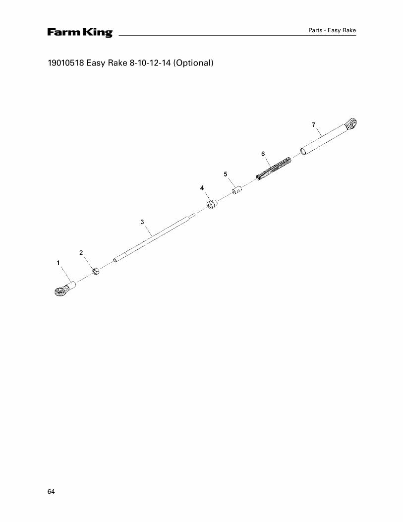
19010518 Easy Rake 8-10-12-14 (Optional)
65
Parts - Easy Rake
Item Part Number Description
1 18032068 Shaft Attachment
2 3020336 Nut M20
3 18032069 Shaft
4 18032070 Shaft Head
5 18032071 Washer
6 11010627 Spring
7 18032072 Cylinder
66
Parts - Easy Rake
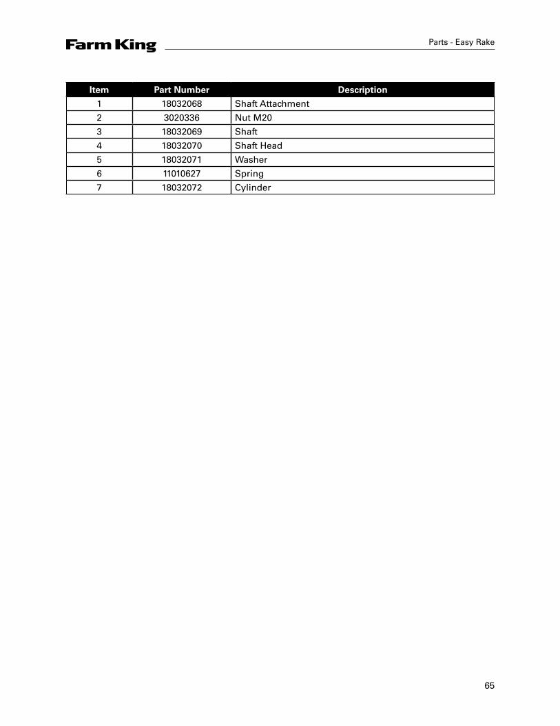
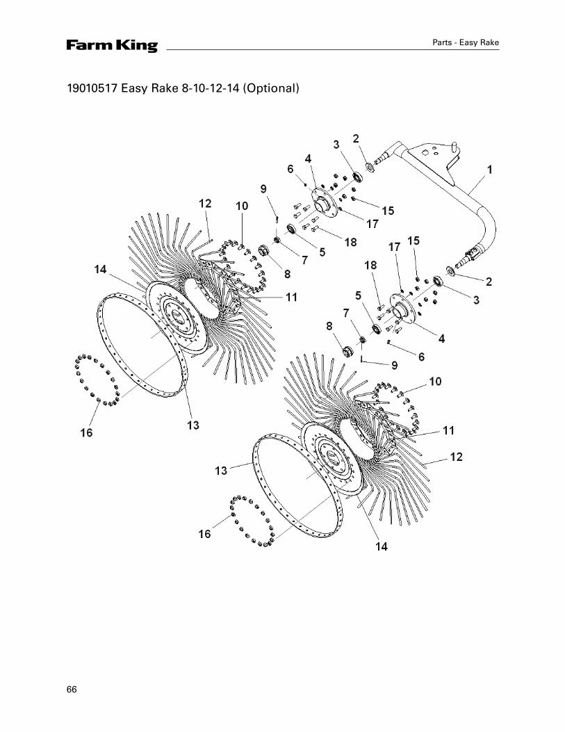
19010517 Easy Rake 8-10-12-14 (Optional)
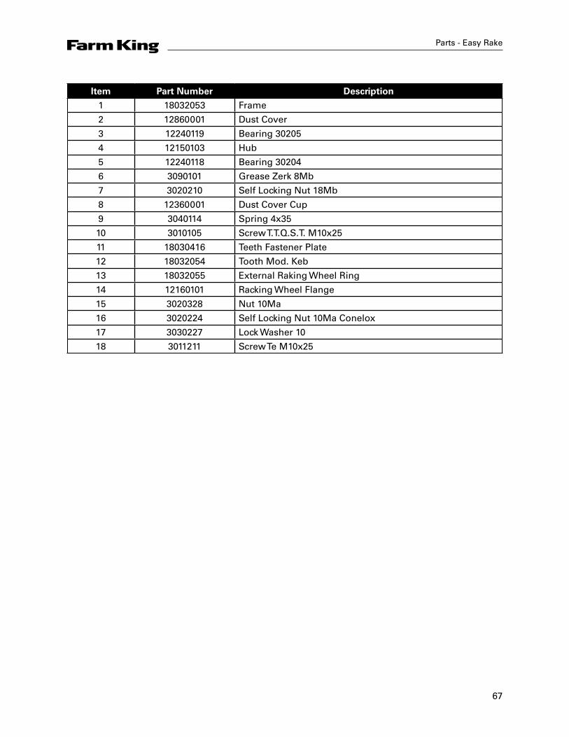
67
Parts - Easy Rake
Item Part Number Description
1 18032053 Frame
2 12860001 Dust Cover
3 12240119 Bearing 30205
4 12150103 Hub
5 12240118 Bearing 30204
6 3090101 Grease Zerk 8Mb
7 3020210 Self Locking Nut 18Mb
8 12360001 Dust Cover Cup
9 3040114 Spring 4x35
10 3010105 Screw T.T.Q.S.T. M10x25
11 18030416 Teeth Fastener Plate
12 18032054 Tooth Mod. Keb
13 18032055 External Raking Wheel Ring
14 12160101 Racking Wheel Flange
15 3020328 Nut 10Ma
16 3020224 Self Locking Nut 10Ma Conelox
17 3030227 Lock Washer 10
18 3011211 Screw Te M10x25
68
Parts - Easy Rake
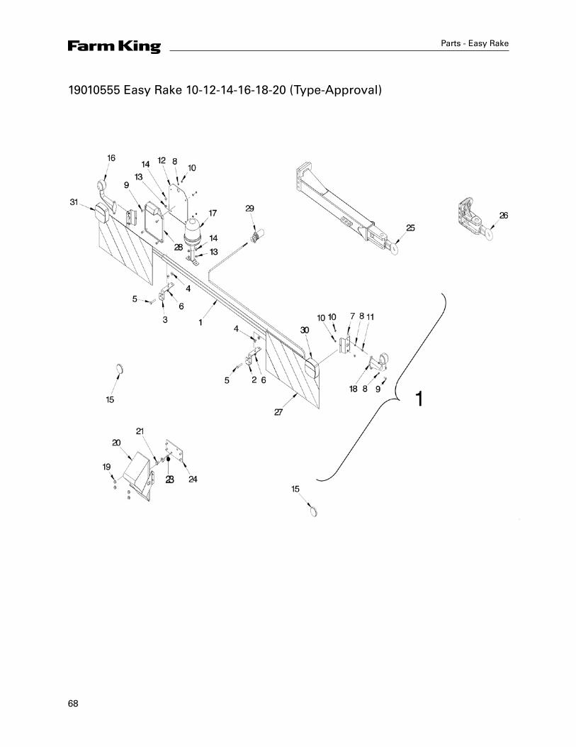
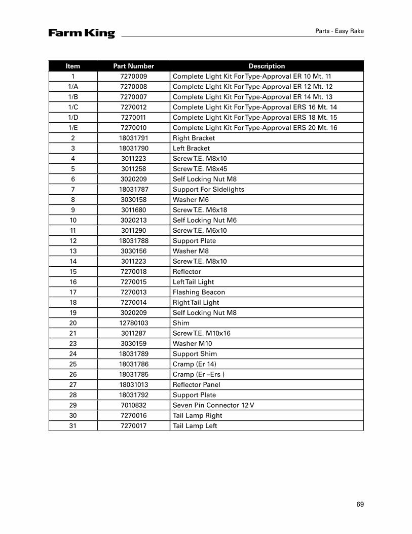
19010555 Easy Rake 10-12-14-16-18-20 (Type-Approval)
69
Parts - Easy Rake
Item Part Number Description
1 7270009 Complete Light Kit For Type-Approval ER 10 Mt. 11
1/A 7270008 Complete Light Kit For Type-Approval ER 12 Mt. 12
1/B 7270007 Complete Light Kit For Type-Approval ER 14 Mt. 13
1/C 7270012 Complete Light Kit For Type-Approval ERS 16 Mt. 14
1/D 7270011 Complete Light Kit For Type-Approval ERS 18 Mt. 15
1/E 7270010 Complete Light Kit For Type-Approval ERS 20 Mt. 16
2 18031791 Right Bracket
3 18031790 Left Bracket
4 3011223 Screw T.E. M8x10
5 3011258 Screw T.E. M8x45
6 3020209 Self Locking Nut M8
7 18031787 Support For Sidelights
8 3030158 Washer M6
9 3011680 Screw T.E. M6x18
10 3020213 Self Locking Nut M6
11 3011290 Screw T.E. M6x10
12 18031788 Support Plate
13 3030156 Washer M8
14 3011223 Screw T.E. M8x10
15 7270018 Reflector
16 7270015 Left Tail Light
17 7270013 Flashing Beacon
18 7270014 Right Tail Light
19 3020209 Self Locking Nut M8
20 12780103 Shim
21 3011287 Screw T.E. M10x16
23 3030159 Washer M10
24 18031789 Support Shim
25 18031786 Cramp (Er 14)
26 18031785 Cramp (Er –Ers )
27 18031013 Reflector Panel
28 18031792 Support Plate
29 7010832 Seven Pin Connector 12 V
30 7270016 Tail Lamp Right
31 7270017 Tail Lamp Left
70
Parts - Easy Rake
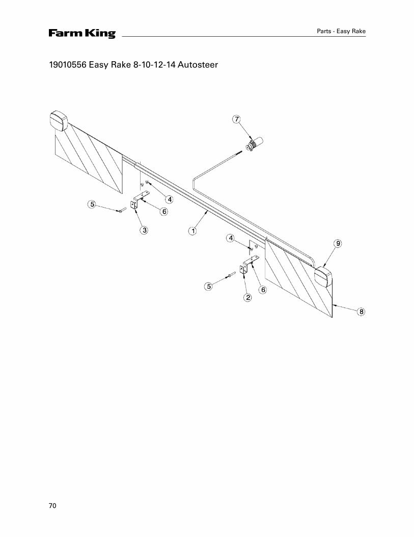
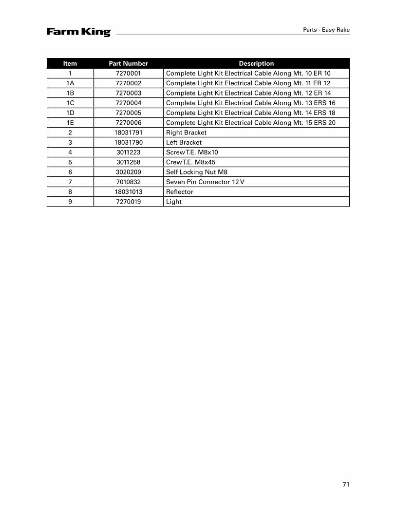
19010556 Easy Rake 8-10-12-14 Autosteer
71
Parts - Easy Rake
Item Part Number Description
1 7270001 Complete Light Kit Electrical Cable Along Mt. 10 ER 10
1A 7270002 Complete Light Kit Electrical Cable Along Mt. 11 ER 12
1B 7270003 Complete Light Kit Electrical Cable Along Mt. 12 ER 14
1C 7270004 Complete Light Kit Electrical Cable Along Mt. 13 ERS 16
1D 7270005 Complete Light Kit Electrical Cable Along Mt. 14 ERS 18
1E 7270006 Complete Light Kit Electrical Cable Along Mt. 15 ERS 20
2 18031791 Right Bracket
3 18031790 Left Bracket
4 3011223 Screw T.E. M8x10
5 3011258 Crew T.E. M8x45
6 3020209 Self Locking Nut M8
7 7010832 Seven Pin Connector 12 V
8 18031013 Reflector
9 7270019 Light

72
Farm King Limited WarrantyThis document limits your warranty rights.
Base Limited WarrantyBuhler Industries Inc. provides this warranty only to original retail purchasers of its product. Buhler Industries Inc. warrants to such purchasers that all Buhler Industries Inc. manufactured parts and components used and serviced as provided for in the Operator’s Manual shall be free from defects in materials and workmanship for a period following delivery to the original retail purchaser of 12 months (80 days for commercial applications). This limited warranty applies only to those parts and components manufactured by Buhler Industries Inc. Parts and components manufactured by others are subject to their manufacturer’s warranties, if any.
Buhler Industries Inc. will fulfill this limited warranty by, at its option, repairing or replacing any covered part that is defective or is the result of improper workmanship, provided that the part is returned to Buhler Industries Inc. within thirty (30) days of the date that such defect or improper workmanship is, or should have been, discovered. Buhler Industries Inc. reserves the right to either inspect the product at the buyer’s location or have it returned to the factory for inspection. Parts must be returned through the selling representative and the buyer must prepay transportation charges.
Buhler Industries Inc. will not be responsible for repairs or replacements that are necessitated, in whole or part, by the use of parts not manufactured by or obtained from Buhler Industries Inc. Under no circumstances are component parts warranted against normal wear and tear. There is no warranty on product pump seals, product pump bearings, rubber product hoses, pressure gauges, or other components that require replacement as part of normal maintenance. Also: Buckets and Bucket Tines carry no warranty, Bent Spears carry no warranty, Snowblower Fan Shafts carry no warranty, Mower Blades carry no warranty, Portable Auger Parts Have Two (2) Year Warranty, Loader Parts Have Two (2) Year Warranty. The purchaser is solely responsible for determining suitability of goods sold. This warranty is expressly in lieu of all other warranties expressed or implied. Buhler Industries Inc. will in no event be liable for any incidental or consequential damages whatsoever. Nor for any sum in excess of the price received for the goods for which liability is claimed.
Repair Parts Limited WarrantyBuhler Industries Inc. warrants Farm King replacement parts purchased after the expiration of the Buhler Industries Inc. Limited Warranty, and used and serviced as provided for in the Operator’s Manual, to be free from defects in materials or workmanship for a period of thirty (30) days from the invoice date for the parts. Buhler Industries Inc. will fulfill this limited warranty by, at its option, repairing or replacing any covered part that is defective or is the result of improper workmanship, provided that the part is returned to Buhler Industries Inc. within thirty (30) days of the date that such defect or improper workmanship is, or should have been, discovered. Such parts must be shipped to Buhler Industries Inc. at the purchaser’s expense.
What is Not CoveredUnder no circumstances does this limited warranty cover any components or parts that have been subject to the following: negligence; alteration or modification not approved by Buhler Industries Inc.; misuse; improper storage; lack of reasonable and proper maintenance, service, or repair; normal wear; damage from failure to follow operating instructions; accident; and/or repairs that have been made with parts other than those manufactured, supplied, and or authorized by Buhler Industries Inc.
Warranty - Easy Rake
73
Authorized Dealer and Labor CostsRepairs eligible for labor under this limited warranty must be made by Buhler Industries Inc. or an authorized Farm King dealer. Buhler Industries Inc. retains the exclusive discretion to determine whether it will pay labor costs for warranty repairs or replacements, and the amount of such costs that it will pay and the time in which the repairs will be made. If Buhler Industries Inc. determines that it will pay labor costs for warranty work, it will do so by issuing a credit to the dealer’s or distributor’s account. Buhler Industries Inc. will not approve or pay invoices sent for repairs that Buhler Industries Inc. has not previously approved. Warranty service does not extend the original term of this limited warranty.
Warranty RequirementsTo be covered by warranty, each Farm King new product must be registered with Buhler Industries Inc. within thirty (30) days of delivery to original retail purchaser. If the customer decides to purchase replacement components before the warranty disposition of such components is determined, Buhler Industries Inc. will bill the customer for such components and then credit the replacement invoice for those components later determined to be covered by this limited warranty. Any such replacement components that are determined not be covered by this limited warranty will be subject to the terms of the invoice and shall be paid for by the purchaser.
Warranty Claims:Warranty requests must be prepared on Buhler Industries Inc. Warranty Claim Forms with all requested information properly completed. Warranty Claims must be submitted within a thirty (30) day period from date of failure repair.
Warranty Labor: Any labor subject to warranty must be authorized by Buhler Industries Inc. The labor rate for replacing defective parts, where applicable, will be credited at 100% of the dealer’s posted shop rate.
Exclusive Effect of Warranty and Limitation of Liability
TO THE EXTENT PERMITTED BY LAW, BUHLER INDUSTRIES INC. DISCLAIMS ANY WARRANTIES, REPRESENTATIONS, OR PROMISES, EXPRESS OR IMPLIED, AS TO THE QUALITY, PERFORMANCE, OR FREEDOM FROM DEFECT OF THE COMPONENTS AND PARTS COVERED BY THIS WARRANTY AND NOT SPECIFICALLY PROVIDED FOR HEREIN.
TO THE EXTENT PERMITTED BY LAW, BUHLER INDUSTRIES INC. DISCLAIMS ANY IMPLIED WARRANTIES OF MERCHANTABILITY AND FITNESS FOR A PARTICULAR PURPOSE ON ITS PRODUCTS COVERED HEREIN, AND DISCLAIMS ANY RELIANCE BY THE PURCHASER ON BUHLER INDUSTRIES INC.’S SKILL OR JUDGMENT TO SELECT OR FURNISH GOODS FOR ANY PARTICULAR PURPOSE. THE PURCHASER’S ONLY AND EXCLUSIVE REMEDIES IN CONNECTION WITH THE BREACH OR PERFORMANCE OF ANY WARRANTY ON PRODUCTS MANUFACTURED BY BUHLER INDUSTRIES INC. ARE THOSE SET FORTH HEREIN. IN NO EVENT SHALL BUHLER INDUSTRIES INC. BE LIABLE FOR INCIDENTAL OR CONSEQUENTIAL DAMAGES (INCLUDING, BY WAY OF EXAMPLE ONLY AND NOT LIMITATION, LOSS OF CROPS, LOSS OF PROFITS OR REVENUE, OTHER COMMERCIAL LOSSES, INCONVENIENCE, OR COST OF REPLACEMENT OF RENTAL EQUIPMENT). IN NO EVENT SHALL FARM KING’S CONTRACT OR WARRANTY LIABILITY EXCEED THE PURCHASE PRICE OF THE PRODUCT.
Warranty - Easy Rake
74
(Note that some provinces or states do not allow limitations on how long an implied warranty lasts or the exclusion or limitation of incidental or consequential damages, so the above limitations and exclusion may not apply to you.) This warranty gives you specific legal rights and you may also have other rights, which vary from province to province or state to state.
Buhler Industries Inc. neither assumes nor authorizes any person or entity, including its selling representatives, to assume any other obligations or liability in connections with the sale of covered equipment, or to make any other warranties, representations, or promises, express or implied, as to the quality, performance, or freedom from defect of the components and parts covered herein. No one is authorized to alter, modify, or enlarge this limited warranty, or its exclusions, limitations and reservations.
Corrections of defects and improper workmanship in the manner, and for the applicable time periods, provided for herein shall constitute fulfillment of all responsibilities of Buhler Industries Inc. to the purchaser, and Buhler Industries Inc. shall not be liable in negligence, contract, or on any other basis with respect to the subject equipment.
This limited warranty is subject to any existing conditions of supply which may directly affect Buhler Industries Inc.’s ability to obtain materials or manufacture replacement parts.
Buhler Industries Inc. reserves the right to make improvements in design or changes in specifications to its products at anytime, without incurring any obligation to owners of units previously sold.
Government Legislation:Warranty terms and conditions are subject to provincial or state legislation.
Important Note: This warranty does not apply to rentals.
Warranty - Easy Rake


www.farm-king.com
a division of Buhler Industries Inc.
1330 43rd Street NWFargo, ND USA 58102Ph.: 701.282.7014 | Fax: 701.282.5865Toll Free: 888.524.1004E-mail: [email protected]
Equipment shown is subject to change without notice. ©2012 Buhler Trading Inc. Printed in USA. TSX:BUI