Embed Size (px)
Citation preview

IMPORTANT INFORMATION IMPORTANT INFORMATION IMPORTANT INFORMATION IMPORTANT INFORMATION KEEP FOR OPERATOR KEEP FOR OPERATOR KEEP FOR OPERATOR KEEP FOR OPERATOR IMPORTANT INFORMATION IMPORTANT INFORMATION IMPORTANT INFORMATION IMPORTANT INFORMATION
Model HY-24EF (New Model)
OPERATOR MANUAL OM-HY-12E/24EPart Number 148667 DOMESTIC
Model: HY-12E and HY-24EHyCapacity HyPerSteam™Atmospheric ConvectionSteamer
Self-ContainedElectric Heated
Model HY-12E
THIS MANUAL MUST BE RETAINED FOR FUTURE REFERENCE. READ,UNDERSTAND AND FOLLOW THE INSTRUCTIONS AND WARNINGSCONTAINED IN THIS MANUAL.
FOR YOUR SAFETYDO NOT STORE OR USE GASOLINE OR OTHER FLAMMABLE VAPORSAND LIQUIDS IN THE VICINITY OF THIS OR ANY OTHER APPLIANCE.
OPERATOR MANUALPart Number 148667 Rev. D

OM-HY-12E/24E
2
IMPORTANT - READ FIRST - IMPORTANTWARNING: THE UNIT MUST BE INSTALLED BY PERSONNEL QUALIFIED TO WORK WITH ELECTRICITY AND
PLUMBING. IMPROPER INSTALLATION CAN CAUSE INJURY TO PERSONNEL AND/OR DAMAGETO THE EQUIPMENT. THE UNIT MUST BE INSTALLED IN ACCORDANCE WITH APPLICABLECODES.
CAUTION: DO NOT INSTALL THE UNIT IN ANY WAY WHICH WILL BLOCK THE RIGHT SIDE VENTS, ORWITHIN 12 INCHES OF A HEAT SOURCE SUCH AS A BRAISING PAN, DEEP FRYER, CHARBROILER OR KETTLE.
NOTICE: Level the unit front to back, or pitch it slightly to the rear, to avoid drainage problems.
CAUTION: DO NOT LOCATE THE CABINET DIRECTLY OVER A FLOOR DRAIN OR FLOOR SINK. HUMIDITYOR WATER FROM A DRAIN WILL DAMAGE ELECTRICAL PARTS OF A UNIT.
WARNING: TO AVOID DAMAGE OR INJURY, FOLLOW THE WIRING DIAGRAM EXACTLY WHEN CONNECTINGA UNIT.
WARNING: DO NOT CONNECT THE DRAIN DIRECTLY TO A BUILDING DRAIN.
CAUTION: DO NOT USE PLASTIC PIPE. DRAIN MUST BE RATED FOR BOILING WATER.
WARNING: BLOCKING THE STEAM GENERATOR OR CAVITY DRAIN SCREEN MAY BE HAZARDOUS.
IMPORTANT: Improper drain connection will void warranty.
WARNING: WHEN YOU OPEN THE DOOR, STAY AWAY FROM STEAM COMING OUT OF THE UNIT. STEAMCAN CAUSE BURNS.
WARNING: BEFORE CLEANING THE OUTSIDE OF THE STEAMER, DISCONNECT THE ELECTRIC POWERSUPPLY. KEEP WATER AND CLEANING SOLUTIONS OUT OF CONTROLS AND ELECTRICALCOMPONENTS. NEVER HOSE OR STEAM CLEAN ANY PART OF THE UNIT.
WARNING: ALLOW COOKING CHAMBERS TO COOL BEFORE CLEANING.
WARNING: CAREFULLY READ THE WARNINGS AND FOLLOW THE DIRECTIONS ON THE LABEL OF EACHCLEANING AGENT. USE SAFETY GLASSES AND RUBBER GLOVES AS RECOMMENDED BYDELIMING AGENT MANUFACTURER.
WARNING: DO NOT MIX DE-LIMING AGENTS (ACID) AND DE-GREASERS (ALKALI) IN THE STEAMGENERATOR OR ON THE COOKING CHAMBER WALLS.
WARNING: DO NOT PUT HANDS OR TOOLS INTO THE COOKING CHAMBER UNTIL THE FAN HAS STOPPEDTURNING.
WARNING: DO NOT OPERATE THE UNIT UNLESS THE REMOVABLE RIGHT SIDE PANELS HAVE BEENRETURNED TO THEIR PROPER LOCATIONS.
NOTICE: Do not use a cleaning or de-liming agent that contains any sulfamic acid or any chloride, includinghydrochloric acid. If the chloride content of any product is unclear, consult the manufacturer.
WARNING: USE OF ANY REPLACEMENT PARTS OTHER THAN THOSE SUPPLIED BY GROEN OR THEIRAUTHORIZED DISTRIBUTOR VOIDS ALL WARRANTIES AND CAN CAUSE BODILY INJURY TO THEOPERATOR AND DAMAGE THE EQUIPMENT. SERVICE PERFORMED BY OTHER THAN FACTORY-AUTHORIZED PERSONNEL WILL VOID ALL WARRANTIES.
WARNING: HIGH VOLTAGE EXISTS INSIDE CONTROL COMPARTMENTS. DISCONNECT FROM BRANCHBEFORE SERVICING. FAILURE TO DO SO CAN RESULT IN SERIOUS INJURY OR DEATH.
2
OM-HY-12E/24E

OM-HY-12E/24E
3
Table of Contents
IMPORTANT OPERATOR SAFETY WARNINGS . . . . . . . . . . . . . . . . . . . . . . . . . . . . . . . . . . . . 2
EQUIPMENT DESCRIPTION . . . . . . . . . . . . . . . . . . . . . . . . . . . . . . . . . . . . . . . . . . . . . . . . . . . . 4
WATER CONDITIONING/REQUIREMENTS . . . . . . . . . . . . . . . . . . . . . . . . . . . . . . . . . . . . . . . . 4
INSTALLATION AND START-UP INSTRUCTIONS . . . . . . . . . . . . . . . . . . . . . . . . . . . . . . . . . . . 6
OPERATION . . . . . . . . . . . . . . . . . . . . . . . . . . . . . . . . . . . . . . . . . . . . . . . . . . . . . . . . . . . . . . . 10
CLEANING . . . . . . . . . . . . . . . . . . . . . . . . . . . . . . . . . . . . . . . . . . . . . . . . . . . . . . . . . . . . . . . . . 12
MAINTENANCE . . . . . . . . . . . . . . . . . . . . . . . . . . . . . . . . . . . . . . . . . . . . . . . . . . . . . . . . . . . . . 14
TROUBLESHOOTING . . . . . . . . . . . . . . . . . . . . . . . . . . . . . . . . . . . . . . . . . . . . . . . . . . . . . . . . 15
PARTS LIST . . . . . . . . . . . . . . . . . . . . . . . . . . . . . . . . . . . . . . . . . . . . . . . . . . . . . . . . . . . . . . . .
WIRING DIAGRAM . . . . . . . . . . . . . . . . . . . . . . . . . . . . . . . . . . . . . . . . . . . . . . . . . . . . . . . . . .
SERVICE LOG . . . . . . . . . . . . . . . . . . . . . . . . . . . . . . . . . . . . . . . . . . . . . . . . . . . . . . . . . . . . . .
16
18
19
REFERENCES . . . . . . . . . . . . . . . . . . . . . . . . . . . . . . . . . . . . . . . . . . . . . . . . . . . . . . . . . . . . . .
WARRANTY PROTECTION . . . . . . . . . . . . . . . . . . . . . . . . . . . . . . . . . . . . . . . . . . . . . . . . . . .
20
21
3
OM-HY-12E/24E
3

OM-HY-12E/24E
4
The HY-24EF has two independentcavities, each with its own steamgenerator (New model shown).
Equipment Description
Your Groen HY-12E HyCapacity HyPerSteam isdesigned to give years of service. It consists of astainless steel cavity (cooking chamber) which is servedby an electrically-heated atmospheric steam generator. The HY-24EF has two cavities and two generators. Two powerful blowers circulate the steam in each cavityto increase heating efficiency.
A dual position pan rack on the left side of the cavitycan be quickly changed to allow for the use of either 12"x 20" steamer pans, or 18" x 26" bake pans. Thefollowing table lists pan capacities:
Pan Size/TypeNumber of Pans
HY-12E HY-24EF12 x 20 x 2 ” (steamer) 12 24
12 x 20 x 4" (steamer) 8 16
13 x 18" (half-size bake) 24 48
18 x 26" (bake) 12 24
A stainless steel cabinet encases the cavity, steamgenerator and a control compartment which houseselectrical components. Access to the controlcompartment is gained by removing the right sidelouvered panel. Door hinges are reversible so that thedoor may be opened to the left or right. Operatingcontrols are on the front panel.
Newer model HY-12E and HY-24EF steamers(manufactured since November 1999) are equippedwith fully electronic controls and a button-activated pre-programmed CLEAN cycle.
These units are readily identified by their unique controlpanels. Touch pad controls, and the distinctive symbolfor steam is integrated into the panel design. The newmodels also have fewer panel louvers on the right sideand rear.
The drain system includes a spray condenser, whichhelps keep steam from coming out of the unit drain orentering the building’s drain.
Water ConditioningIt is essential to supply the steam generator with waterthat will not form scale. Even though the steamgenerator is engineered to minimize scale formation,scale development depends on the hardness of yourwater and the number of hours the equipmentoperates.
In some areas of the country, water is low enough inminerals to avoid scale formation. But most watersupplies are full of minerals which form scale. It is thisscale which could lead to an early component failure.Your water utility or treatment specialists can test andtell you about the minerals in your water. The watergoing to the steam generator should have between 10and 30 parts per million (ppm) total dissolved solids
(TDS) and should have a pH (acidity rating) of 7.0 orhigher.
Please follow these simple precautions:
1. The best way to prevent scale is to use a GroenPureSteem™ Water Treatment System which hasbeen specifically designed for Groen steamers andcombination ovens. Do not rely on unprovenwater treatment systems sold for scaleprevention and removal. They are notspecifically designed to work with Groensteamers and combination ovens.
4
OM-HY-12E/24E

OM-HY-12E/24E
5
The optional separate water intake can significantly reduce treated watervolume requirements.
2. A well-maintained water treatment system and aregular cartridge replacement schedule isessential.
3. Using a Groen PureSteem™ Water TreatmentSystem will provide longer steam generator/boilerlife, higher steam capacity, and reducemaintenance requirements.
4. If you notice a slowdown in steam production or anincrease in deliming, have the steamer checked forscale build-up. This could be an indication that thewater treatment cartridges need replacing. Heavyscale reduces the unit’s ability to boil water, andcan even cause component failure.
.
5
OM-HY-12E/24E
5

OM-HY-12E/24E
6
Installation and Start-Up
WARNINGTHE UNIT MUST BE INSTALLED BY PERSONNEL WHO ARE QUALIFIED TO WORK WITHELECTRICITY AND PLUMBING. IMPROPER INSTALLATION CAN CAUSE INJURY TOPERSONNEL AND/OR DAMAGE TO THE EQUIPMENT. THE UNIT MUST BE INSTALLED INACCORDANCE WITH APPLICABLE CODES.
WARNINGTO AVOID DAMAGE OR INJURY, FOLLOW THE ELECTRICAL SCHEMATIC EXACTLYWHEN CONNECTING THE UNIT.
CAUTIONDO NOT INSTALL WITH THE RIGHT SIDE VENTS BLOCKED OR WITHIN 12 INCHES OF AHEAT SOURCE (BRAISING PAN, DEEP FRYER, CHAR BROILER, OR KETTLE). TO AVOIDDRAINAGE PROBLEMS, LEVEL THE UNIT FRONT TO BACK.
A. Installation
6
OM-HY-12E/24E

OM-HY-12E/24E
7
1. Electrical Supply Connection
a. Panel Removal
Open the wiring and control panel by removing thethree screws on the right side panel and sliding thepanel forward. Set the panel aside.
b. Supply Voltage
The unit must be operated at the rated nameplatevoltage, plus or minus 10 percent.
c. Terminal Block
The terminal block for incoming power is located atthe back of the control compartment. The ground terminal is located in the wiringcompartment above the terminal block.
The unit must have a separate ground wire forsafe operation. This wire must be at least 8 AWG for 208/240V, or 10 AWG for 480V.
d. Supply Wire
To determine the wire you need for the powersupply, find the operating voltage and phase on theunit data plate. Refer to the table below or to thelabel on the unit’s back for correct wire size andinsulation temperature rating. The “ElectricalSupply Connection” label inside the unit givesdirections for proper connection of the terminalblock jumpers.
The specified wire must be used in order to meetUnderwriters Laboratories and National ElectricCode requirements.
The knockout hole is sized for a two inch conduitfitting.
e. Branch Circuit Protection
Groen strongly recommends that the HY-12ESteamer or each cavity of the HY-24EF have itsown branch circuit protection. Each current-carrying conductor must have overcurrentprotection. Refer to the label for proper wire sizeand type. Watertight connections to the unit arerequired.
2. Water Connection(s):
Install a check valve to prevent back flow in theincoming cold water line, as required by local plumbingcodes. Water pressure in the line should be between30 and 60 PSIG (210 and 420 kPa). If pressure isabove 60 PSIG, a pressure regulator will be needed. A inc h R connector (garden hose type) is used toattach the water supply to the water inlet valve. Theminimum water feed line diameter is inc h (13mm). Use a washer in the hose connection. Do not allow theconnection to leak, no matter how slow it may be.
If you have the twin water connection option, putthe treated water (softened) to the bottom intake(facing the rear of the unit), and untreated water tothe top. Connections for both are made asdescribed above.
VoltageWiring - Insulation Rating
Amperes Maximum KWTHWN (70ºC) THWN (90ºC)
208 Volt, 3 Phase Not Approved 1/0 AWG 92 32.5
240 Volt, 3 Phase Not Approved 1 AWG 80 32.5
480 Volt, 3 Phase 1 AWG 6 AWG 40 32.5
7
OM-HY-12E/24E
7

OM-HY-12E/24E
8
Installation of drain line without drain box(tabletop models only).
Drain Connection with Drain Box (All units areshipped from the factory with a drain box). Oldmodel shown.
3. Drain Connection
The HY-12E/24E Steamer must be leveled front toback or pitched slightly to the rear by adjustment ofthe bullet feet on the cabinet base.
All units are shipped from the factory with a drainbox and vent pipe. The drain box and vent pipeprovide the necessary air gap when properlyinstalled. The illustrations below show properinstallation of drain lines from the drain box, and fortabletop installation, without a drain box.
CAUTIONDO NOT CONNECT THE HOSE DIRECTLY TOA BUILDING DRAIN. BLOCKING THE DRAINCOULD BE DANGEROUS.
Do not create any water traps in the drain line. Atrap would cause pressure to build up inside thecavity during steaming and make the door gasketleak.
NOTE: Improper drain connection will void thewarranty.
INSTALLATION OPTION ONE: From stainless steelelbow (P/N 092273) to nearby floor drain, use RadiatorHose (rated at least 212ºF) and one additional hoseclamp (P/N 013616).
INSTALLATION OPTION TWO: Using the hose (P/N080688) and two hose clamps (P/N 013616), connecttwo inch copper tube to floor drain. NOTE: Drain linesmust be pitched downward at approximately inc h perfoot. No water traps should be allowed in the drain line.
IMPORTANT: Leave two inches free air gap tobuilding drain.
8
OM-HY-12E/24E
OM-HY-12E/24E
9
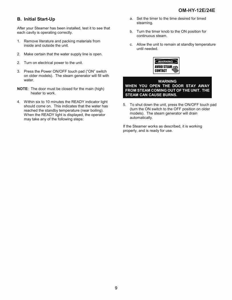
B. Initial Start-Up
After your Steamer has been installed, test it to see thateach cavity is operating correctly.
1. Remove literature and packing materials frominside and outside the unit.
2. Make certain that the water supply line is open.
2. Turn on electrical power to the unit.
3. Press the Power ON/OFF touch pad (“ON” switchon older models). The steam generator will fill withwater.
NOTE: The door must be closed for the main (high)heater to work.
4. Within six to 10 minutes the READY indicator lightshould come on. This indicates that the water hasreached the standby temperature (near boiling). When the READY light is displayed, the operatormay take any of the following steps:
a. Set the timer to the time desired for timedsteaming.
b. Turn the timer knob to the ON position forcontinuous steam.
c. Allow the unit to remain at standby temperatureuntil needed.
WARNINGWHEN YOU OPEN THE DOOR STAY AWAYFROM STEAM COMING OUT OF THE UNIT. THESTEAM CAN CAUSE BURNS.
5. To shut down the unit, press the ON/OFF touch pad(turn the ON switch to the OFF position on oldermodels). The steam generator will drainautomatically.
If the Steamer works as described, it is workingproperly, and is ready for use.
9
OM-HY-12E/24E
9

OM-HY-12E/24E
10
Manual “On”Position60 Minute Timer
Power On/OffButton
Ready IndicatorLight
Power IndicatorLight
Service IndicatorLight Delime Indicator
Light
Hi Temp Indicator Light
Clean Cycle Button
Operation
WARNINGANY POTENTIAL USER OF THE EQUIPMENT SHOULD BE TRAINED IN SAFE ANDCORRECT OPERATING PROCEDURES.
A. ControlsOperator controls are located on the front right of the unit.
10
OM-HY-12E/24E

OM-HY-12E/24E
11
The control panel on new models has the following touchpads and indicator lights:
! The ON/OFF touch pad gets the HyPerSteamready for use, or shuts it off.
! The READY indicator light shows that the steamgenerator is at standby temperature and thecavity is hot enough to begin steaming.
! The DELIME indicator light is lit when the unit isoperating in the cleaning mode.
! The SERVICE indicator light shows when thewater level probes have stopped working, andneed to be cleaned (normally an indication oflime deposits).
When one probe is not working, the DELIMElight flashes briefly every few seconds. If bothprobes fail, the SERVICE light flashescontinuously and the beeper will sound.
! The HI TEMP indicator light comes on when thesteam generator is too hot.
The unit will automatically shut off, and cannotbe turned on again until the steam generatorcools and the HI TEMP indicator light goes out.
! The TIMING indicator light stays on when thetimer is running.
! The CLEAN touch pad is used to start theautomatic 30 minute cleaning cycle.
The timer is used in three ways:
1 In the OFF position the steam generator stays ata low boil or “holding” temperature.
2 When a cook time is set, the unit steams untilthe timer runs down to OFF. Steaming stops, theDONE light (a red light on older models) comeson and a beeper sounds.
3 With the timer turned to the ON position, the unitsteams continuously. The green light stays lit.The steamer will not time down.
B. Operating Procedure1. Press the ON switch/pad for the steamer. The
steam generator will fill, and heat until the READYlight comes on. (About 10 minutes.)
2. Load food into pans in uniform layers. Pans shouldbe filled to about the same levels, and should beeven on top.
3. Open the door and slide the pans onto the supports. If you will only be steaming one pan, put it in themiddle position.
4. Close the door. With the READY indicator lit, takeone of the following steps:
! If you want to steam the food for a certain lengthof time, set the timer for that period. The timerwill automatically run the steamer for the set timeand then turn it off. A red light will come on anda beeper will sound. Steam production stops.
! If you want to steam continuously, turn the timerto the manual ON position. A green light willcome on. The unit will continue steaming untilyou stop it by turning the timer to OFF. Whensteaming continuously YOU MUST CONTROLSTEAMING TIME.
WARNINGWHEN YOU OPEN THE DOOR, STAY AWAY FROMTHE STEAM COMING OUT OF THE UNIT. THESTEAM CAN CAUSE BURNS.
5. Open the door. Remove the pans from the steamer,using hot pads or oven mitts to protect your handsfrom the hot pans.
6. To shut down the unit, press the ON switch/pad toOFF. The steam generator will automatically drain.
11
OM-HY-12E/24E
11

OM-HY-12E/24E
12
Cleaning
To keep your HY-12E/24EF Steamer in proper working condition, use the following procedure to clean the unit. Thisregular cleaning will reduce the effort required to clean the steam generators and cavities.
A. Suggested Tools
1. Mild detergent2. Stainless steel exterior cleaner such as Zepper3. Steam generator de-liming agent, such as
Groen Delimer Descaler, Lime-Away® or anequivalent. A liquid de-liming agent will beeasier to use than crystals or powders. Seethe warning about chlorides, below.
4. De-greaser, such as EncompasS®, Malone34®, Puritan Puribrute®, or Con-Lie®
5. Cloth or sponge6. Plastic wool or a brush with soft bristles7. Spray bottle8. Measuring cup9. Nylon pad10. Towels11. Plastic disposable gloves12. Funnel
B. Procedure
1. Unit Exterior
a. Prepare a warm solution of the mild detergent asinstructed by the supplier. Wet a cloth with thissolution and wring it out. Use the moist cloth toclean the outside of the unit. Do not allow freelyrunning liquid to touch the controls, the controlpanel, any electrical part, or any open louver.
b. To remove material which may be stuck to theunit, use plastic wool, a fiber brush, or aplastic or rubber scraper with a detergentsolution.
c. Stainless steel surfaces may be polished witha recognized stainless steel cleaner such asZepper®.
WARNING
DISCONNECT THE POWER SUPPLYBEFORE CLEANING THE OUTSIDE OFTHE STEAMER.
KEEP WATER AND CLEANINGSOLUTIONS OUT OF CONTROLS ANDELECTRICAL COMPONENTS. NEVERHOSE OR STEAM CLEAN ANY PART OFTHE UNIT.
DON’T MIX DE-LIMING AGENTS (ACID)WITH DE-GREASERS (ALKALI)ANYWHERE IN THE UNIT.
AVOID CONT ACT W ITH ANYCLEANERS, DE-LIMING AGENT OR DE-GREASER AS RECOMMENDED BY THESUPPLIER. MANY ARE HARMFUL.READ THE WARNINGS AND FOLLOWTHE DIRECTIONS!
EVEN WHEN THE UNIT HAS BEEN SHUTOFF, DON’T PUT HANDS OR TOOLSINTO THE COOKING CHAMBER UNTILTHE FAN HAS STOPPED TURNING.
DON’T OPERATE THE UNIT UNLESSTHE TWO REMOVABLE INTERIORPARTITIONS HAVE BEEN PUT BACK INTHEIR PROPER LOCATIONS.
DON’T USE ANY CLEANING OR DE-LIMING AGENT THAT CONTAINS ANYSULFAMIC AGENT OR ANY CHLORIDE,INCLUDING HYDROCHLORIC ACID(HCl). TO CHECK FOR CHLORIDECONTENT SEE ANY MATERIAL SAFETYDATA SHEETS PROVIDED BY THECLEANING AGENT MANUFACTURER.
IMPORTANTDO NOT USE ANY METAL MATERIAL (SUCH AS METAL SPONGES) OR METAL IMPLEMENT (SUCH AS ASPOON, SCRAPER OR WIRE BRUSH) THAT MIGHT SCRATCH THE SURFACE. SCRATCHES MAKE THESURFACE HARD TO CLEAN AND PROVIDE PLACES FOR BACTERIA TO GROW. DO NOT USE STEELWOOL, WHICH MAY LEAVE PARTICLES IMBEDDED IN THE SURFACE WHICH COULD EVENTUALLY CAUSECORROSION AND PITTING.
12
OM-HY-12E/24E

OM-HY-12E/24E
13
Steam Generator and Cooking Chamber
Regular deliming, depending on your steamer usageand local water quality, must be done to enhanceperformance and prolong the life of yourHyPerSteam™ convection steamer. Steamer must beturned off after every use to prevent lime scale buildup- do not run steamer continuously.
ALWAYS USE HOT PADS OR MITTS WHEN HANDLING HOT STEAMER PANELS OR RACKS.
RECOMMENDED TOOLS & CLEANERS:- Groen Delimer/Descaler (Part Number114800). Do NOT use any productcontaining chlorides or sulfamic acid,including hydrochloric acid .- Nylon scrub pad, cloth and/or sponge
DELIMING STEPS (Use Touch Pad):
STEP 1 Press ON/OFF to turn steamer off. Open door.
STEP 2 Let cavity cool for 5 minutes orlonger. While cool, wipe out cavity.
STEP 3 Pour 2 pints (4 cups) of delimer intodeliming port before delime cycle isstarted and then close port. Double-stacked unit cavities must be delimedseparately. Select which cavity todelime first.
STEP 4 Press and hold CLEAN while alsoturning steamer on by pressingON/OFF, until only DELIME andPOWER lights remain on (all lights willturn on, then off, except DELIME andPOWER).
STEP 5 Delime cycle will start, taking about 30minutes. When delime cycle iscomplete, DELIME light will appear,DONE light will flash and beeper willbeep.
STEP 6 Press ON/OFF to turn steamer off. Letcavity cool for 5 minutes or longer. Open door, wipe out inside of cavityand wipe door gasket. Close door.
STEP 7 To use steamer, press ON/OFF. When READY light appears, steameris ready to use.
STEP 8 HY12E/HY12G DOUBLE STACKONLY: Double-stacked unit cavitiesmust be delimed separtely. RepeatStep 1 through Step 8 to delime othercavity.
NOTES: - If DELIME light flashes rapidly (5 times per second),press DELIME to restart delime cycle.
- If power outage occurs during deliming, delime cyclemust be restarted. Press DELIME.
- For best performance, do not interrupt delime cycle. If delime cycle must be stopped, press ON/OFF to turnon. Set timer for 5 minutes. After beeper beeps, pressON/OFF to turn off. Let cavity cool for 5 minutes orlonger, carefully open door(s) and wipe out cavitycompletely.
13
OM-HY-12E/24E
13

OM-HY-12E/24E
14
MaintenanceThe HY-12E Steamer is designed for minimummaintenance, and no user adjustments should benecessary. After prolonged use some parts may needto be replaced.
If there is a need for service, only Groen personnel orauthorized Groen representatives should perform thework.
Always supply water with a low mineral content thatmeets the standards outlined in the waterConditioning section of this manual.
If steam or condensate is seen leaking from around thedoor, take the following steps:
1. Check the door gasket. Replace it if it is crackedor split.
2. Inspect the cooking chamber drain to be sure it isnot blocked.
3. Adjust the door latch pin to allow for changes thatoccur as the gasket ages.
a. Loosen the lock nut at the latch pin base, andturn the latch pin 1/4 turn clockwise. Retightenthe lock nut.
b. Run the unit again to test for further leakage.
c. Repeat the adjustment as necessary until thedoor fits tightly enough to prevent leakage.
14
OM-HY-12E/24E

OM-HY-12E/24E
15
TroubleshootingYour Groen Steamer is designed to operate smoothly and efficiently if properly maintained. However, the following is alist of checks to make in the event of a problem. Wiring diagrams are furnished inside the service panel, and at theback of this manual. If an item on the check list is marked with (X), it means that the work should be performed by afactory-authorized service representative.
SYMPTOM WHO WHAT TO CHECK
No indicator lights when ON switch ispressed
User a. Is electrical power supply connected?b. Are building circuit breakers or fuses all right?
Steam generator does not fill withwater
User a. Is the ON switch depressed?b. Is the electric cupply connected?c. Is the water supply connected?d. Is the water turned on?e. Is the water pressure too low? (Below 30 PSI or
210 kPa)f. Is the screen (filter) at the water connection
clogged?g. Has the steam generator been de-limed? (Refer to
the Cleaning Section).
No steam User a. Is the ON switch depressed?b. Is the water supply connected?c. Is the water turned on?d. Are the steamer doors open?e. Has the steam generator been de-limed? (Refer to
the Cleaning Section).
SERVICE light comes on after tenminutes. (See Cleaning Section)
User a. Is the water supply connected?b. Is the water supply hose kinked?c. Is the water turned on?d. Has the steam generator been de-limed? (See
Cleaning Section
Excessive steam escaping from therear of unit
User a. Is the water spray hose kinked or obstructed?
Auth Service RepOnly
b. Is the water solenoid connected? (X)c. Is the drain properly vented? (X)
15
OM-HY-12E/24E
15

16
OM-HY-12E/24E
PARTS LIST - HY-12E

17
OM-HY-12E/24E
PARTS LIST - HY-12EParts List - HY-12E
Key Part No. Key Part No.1 119815 30 1198132 106270 31 1422443 121716 32 119875
x 1463414 106306 x 1231315 096809 x 1413006 119897 x 0038237 106412 x 1063548 070185 x 1422389 100934 x 10630910 071235 x 12972311 096826 x 10620912 106392 x 09686813 071234 x 14109314 141336 x 10631615 099250 x 14633916 088865 x 14634017 141424 x 10629418 141285 x 10644519 096857 x 11987820 106365 x 11988621 123100 x 10096022 141082 x 14108423 137233 x 11986224 143255 x 12312525 119833 x 12312026 146880 x 12312227 141189 x 123124
141190 x 148109141191 x 148107
28 094161 x 14810829 042366
x - Item not depicted/called out in drawing or photograph.
Right Side PanelDrip Tray
Harness, ControlHarness, Heater
Blower CoverRight Pan Rack
Door Pin Lock Nut
Door GasketDoor Handle
Motor Shaft SealDrain ValveSteam Inlet Port
Left Side Panel
Top Panel
Electrical Panel AssemblyPC Board Assembly
Relay, 12VDCDescription
To order parts, contact your Groen Authorized Service Agent. Supply the model designation, serialnumber, part description, part number, quantity, and when applicable, voltage and phase.
Transformer 20VA
Door Assembly, Complete
Water Level Probe LeftWater Level Probe Right
Description
Capacitor, 4MFTransformer 208/240v Primary/
Contactor24v secondary, 75VA
Gasket, Steam Inlet PortReady Thermostat
FuseholderFuseGround Terminal
Door Switch
Terminal BlockWater Valve, Condensate
TimerPressure Relief Valve
Water Valve, Fill
Torroid (480V only)Motor AssemblyElement 208v 9KW
Harness, TransformerHarness, Control Board
Harness, Jumper
Control BoardLight & Timer BoardControl Board Cover
Harness, Control Board to Timer BoardJumper, Voltage Select Harness, Power
Harness, Timer
Door Latch PinFront Panel Overlay
Knob
Harness, Ready Switch
Cavity Fan
Left Pan RackGenerator Assembly
Flow Reducer, Condensate
Harness, Voltage Select ElectricHarness, Voltage Select
Element 240v 9KWElement 480v 9KWThermostat AssemblyGasket, Element

18
OM-HY-12E/24E
WIRING DIAGRAM - HY-12E

OM-HY-12E/24E
16
Service Log
Model No.
Serial No.
Date Purchased
Purchase Order No.
Purchased From
Location
Date Installed
For Service Call
Date Maintenance Performed Performed by
19
OM-HY-12E/24E

OM-HY-12E/24E
17
References
UNDERWRITERS LABORATORIES, INC.333 Pfingsten RoadNorthbrook, Illinois 60062
NATIONAL FIRE PROTECTION ASSOCIATION60 Battery March ParkQuincy, Massachusetts 002269
NFPA/70 The National Electric Code
NATIONAL SANITATION FOUNDATION3475 Plymouth RoadAnn Arbor, Michigan 48106
20
OM-HY-12E/24E
20
NSF INTERNATIONAL789 N. Dixboro Rd.P.O. Box 130140Ann Arbor, Michigan 48113-0140

18
LIMITED WARRANTY TOCOMMERCIAL PURCHASERS*
(Continental U.S. and Canadian Sales Only)
Groen Foodservice Equipment (ìGroen Equipmentî) has been skillfully manufactured, carefully inspected, andpackaged to meet rigid standards of excellence. Groen warrants its Equipment to be free from defects in materialand workmanship for (12) twelve months with the following conditions an subject to the following limitations.
I. This parts and labor warranty is limited to Groen Equipment sold to the original commercialpurchaser/users (but not original equipment manufacturers {O.E.M.}), at its original place of installationin the continental United States, Hawaii and Canada.
II. Damage during shipment is to be reported to the carrier, is not covered under this warranty, and is thesole responsibility of the purchaser/user.
III. Groen, or an authorized service representative, will repair or replace, at Groenís sole election, anyGroen equipment, including but not limited to, drawoff valves, safety valves, gas and electriccomponents, found to be defective during the warranty period. As to warranty service in the territorydescribed above, Groen will absorb labor and portal to portal transportation costs (time and mileage) forthe first twelve (12) months from date of installation or fifteen (15) months from date of shipment fromGroen.
IV. This warranty does not cover boiler maintenance, calibration, periodic adjustments as specified inoperating instructions or manuals, and consumable parts such as scraper blades, gaskets, packing,etc., or labor costs incurred for removal of adjacent equipment or objects to gain access to GroenEquipment. This warranty does not cover defects caused by improper installation, abuse, carelessoperation, or improper maintenance of equipment. This warranty does not cover damage caused bypoor water quality or improper boiler maintenance.
V. THIS WARRANTY IS EXCLUSIVE AND IS IN LIEU OF ALL OTHER WARRANTIES, EXPRESS ORIMPLIED, INCLUDING ANY IMPLIED WARRANTY OF MERCHANTABILITY OR FITNESS FOR APARTICULAR PURPOSE, EACH OF WHICH IS HEREBY EXPRESSLY DISCLAIMED. THEREMEDIES DESCRIBED ABOVE ARE EXCLUSIVE AND IN NO EVENT SHALL GROEN BE LIABLEFOR SPECIAL, CONSEQUENTIAL OR INCIDENTAL DAMAGES FOR THE BREACH OR DELAY INPERFORMANCE OF THIS WARRANTY.
VI. Groen Equipment is for commercial use only. If sold as a component of another (O.E.M.)Manufacturerís equipment, or if used as a consumer product, such Equipment is sold AS IS and withoutany warranty.
*(Covers all Foodservice Equipment Ordered after October 1, 1995)
21
OM-HY-12E/24E

NOTES
22
OM-HY-12E/24E
22

23
OM-HY-12E/24E
NOTES

OM-HY-12E/24EPart Number 148667 Rev. D
1055 Mendell Davis DriveJackson, MS 39272Telephone 601 372-3903Fax 601 373-9587www.groen.com