Embed Size (px)
Citation preview

OPERATOR MANUAL & PARTS CATALOG
143322 v1.0
D E G E L M A N I N D U S T R I E S L T D.B O X 8 3 0 - 2 7 2 I N D U S T R I A L D R I V E ,R E G I N A , S K , C A N A D A , S 4 P 3 B 1FA X 306.543.2140 P H 3 0 6 . 5 4 3 . 4 4 4 71 . 8 0 0 . 6 6 7 . 3 5 4 5 D E G E L M A N . C O M
CASE STEIGER QUADTRAC 450/500/550/600

Record Serial Number:
...........................................................
QUICK GUIDE INDEX
Introduction 1
Safety 2
Operation 4
Transport & Storage 6
Troubleshooting 7
Maintenance 8
Blade Overview / Options 11
Center Section Components 12
Wing Section Components 13
Tilt Frame Components 14
Pivot Mounting / Wing Angle Components 15
Cylinders 16
Pivot & Main Frame 17
Axle & Side Brackets / Installation 18
Hyd Coupler, Ball Valve, & Tow Brackets 20
Hydraulic Routing 21-25
Mounting Procedure 26
Warranty 27
D E G E L M A N I N D U S T R I E S L T D.B O X 8 3 0 - 2 7 2 I N D U S T R I A L D R I V E ,R E G I N A , S K , C A N A D A , S 4 P 3 B 1FA X 306.543.2140 P H 3 0 6 . 5 4 3 . 4 4 4 71 . 8 0 0 . 6 6 7 . 3 5 4 5 D E G E L M A N . C O M
IMPORTANT:
READ MANUAL


-1-143322 - PileDriver (15-March-2012)
This manual has been designed to help you with three extremely important issues: Operation, Safety, and Maintenance. It is strongly recommended that you read through the entire manual and review it annually for: •yourownpersonalsafety. •thesafetyofothers. •helpfulandeffectiveoperation techniques. •maintenanceprocedures. •preventativemaintenance.
Your authorized Degelman dealer can be contacted for ordering any replacement parts, decals, or manuals. Since many of our parts are specially designed specifically for this dozer blade we strongly recommend you always replace them with genuine Degelman parts only.
This manual and its contents were current at the time of its first printing. To increase product performance and operation, some part modifications and changes may occur that are not reflected in this manual.
Note: The description “Right”or“Left” as used in this manual is determined by the direction the tractor will travel while in use (unless otherwise stated).
Degelman is proud to welcome you to our rapidly increasing family of high quality and dependable product owners. This product was designed and built specifically for you, the customer. Through our research and with your input and feedback, we present to you our PileDriver Blade.
Designed with durability, safety, and performance in mind, this dozer blade is ready for years of quality service. In order to help you keep your dozer blade in top operating condition we have provided you with this manual.
Your serial number isfound on the serial number plate.
It is important to record the serial and model number of your dozer for proof of ownership and for any required service or maintenance assistance.
Serial Number Owner Name Model Purchase Date
Dealer Name Address Phone
WELCOME PROOF OF OWNERSHIP
ABOUT THIS MANUAL
Introduction
Serial Number Plate
LeftSide
RightSide
The PileDriver Blade consists of a dual-wing dozer blade connected to a pivot/main frame assembly.
Typically, this assembly mounts to side and axle brackets that are bolted securely onto the frame of your tractor.
The blade is attachable/detachable with a simple HQT (Hydraulic Quick-Tach) mounting system and hydraulic hook-up.
The PileDriver Blade has options for three hydraulically controlled ranges of motion – lift, wing angle & tilt.
DESCRIPTION
Lift Wing Angle Tilt
-2-143322 - PileDriver (15-March-2012)
Safety
Why is SAFETY important to YOU?
3 BIG Reasons:
• Accidents Can Disable and Kill •AccidentsAreCostly •AccidentsCanBeAvoided
. . . for your own safety and that of others!
- If you are not familiar with basic agriculture & industrial safety, you must get training.
- Owners of equipment must give operating instructions to other operators such as family members or a hired hand.
- Making any design changes to equipment could cause a hazard, damage your machine & void your warranty.
YOU are responsible for the SAFE operation and maintenance of your Degelman implement. YOU must ensure that you and anyone else who is going to operate, maintain, or work around the machine be familiar with the operating and maintenance procedures, and related SAFETY information contained in this manual. This manual will take you step-by-step through your working day and will alert you to good safety practices that should be adhered to while operat ing this equipment.
Remember, YOU are the key to safety. Good safety practices not only protect you, but also the people around you. Make these practices a working part of your safety program. Be certain that EVERYONE operating this equipment is familiar with the recommended operating and maintenance procedures and follows all the safety precautions. Most accidents can be prevented. Do not risk injury or death by ignoring good safety practices.
•Ownersmustgiveoperatinginstructionstooperators or employees before allowing them to operate the unit, and at least annually thereafter per OSHA regulation 1928.57.
•Themostimportantsafetydeviceonthisequipment is a SAFE operator. It is the operator’s responsibility to read and understand ALL Safety and Operating instructions in the manual and to follow these. All accidents can be avoided!
•ApersonwhohasnotreadandunderstoodALLoperating and safety instructions is not qualified to operate the machine. An untrained operator exposes himself and bystanders to possible serious injury or death.
•Donotmodifytheequipmentinanyway.Unauthorized modifica tion may impair the function and/or safety and could affect the life of the equipment.
DANGER: Indicates an imminently hazardous situation that, if not avoided, WILL result in death or serious injury if proper precautions are not taken.
WARNING: Indicates a potentially hazardous situation that, if not avoided, COULD result in death or serious injury if proper precautions are not taken.
CAUTION: Indicates a potentially hazardous situation that, if not avoided, MAY result in minor or moderate injury if proper practices are not taken, or, serves as a reminder to follow appropriate safety practices.
Note the use of the Signal Words: DANGER, WARNING, and CAUTION with the safety messages. The appropriate Signal Word has been selected using the following guidelines:
SIGNAL WORDS
The Safety Alert Symbol identifies important safety messages applied to the dozer blade and in this manual. When you see this symbol, be alert to the possibility of injury or death. Follow the instructions provided on the safety messages.
The Safety Alert Symbol means:
ATTENTION! BECOME ALERT!
YOUR SAFETY IS INVOLVED!
SAFETY ALERT SYMBOL
YOU are RESPONSIBLE

-3-143322 - PileDriver (15-March-2012)
Wear Protective Equipment Note: Before working on machine, always turn
tractor off, set controls in neutral, and remove ignition key.
• Wear proper safety equipment such as safety glasses and shoes, hearing protection, hard hats, or any other appropriate items to prevent injury.
• Loss of hearing or hearing impairment may result from prolonged exposure to loud noise. Wear
suitable hearing protective devices such as earmuffs or earplugs to protect your hearing.
•Safelyoperatingthis equipment requires the full attention of the operator. Do not wear radio or music headphones, or talk on your phone while operating this machine. Never operate while under the influence of alcohol or drugs or allow anyone under the influence to operate the tractor.
Doctor Ambulance Hospital Fire Department
Prepare for Emergencies•Keepafirstaid kit and
fire extinguisher handy.
•Keep emergency numbers for doctor, hospital, ambulance, and fire department near your phone.
HYDRAULIC•Keep all parts clean. •Replace worn or damaged parts.•Don’t try any makeshift repairs. •Before operating check that everything is tight and
not broken.•Wear gloves and eye protection when searching
for leaks. Use a piece of wood or cardboard but not your hand. High pressure oil will penetrate your skin. If that happens you risk serious injury.
BLADE•Lower blade to the ground when not in use. •Keep clear of blade when tractor is running. •Keep hands & feet away from under blade. •Turn engine off when hooking up hydraulics.
TRANSPORTING•Lift blade up then hold with safety chain.•Make sure SMV sign & reflectors are clean.•Use your hazard lights.
GENERAL SAFETY
1. Read and understand the Operator's Manual and all safety signs before using. Review safety related items with all operators annually.
2. Lower blade to ground, stop tractor engine, place all controls in neutral, set park brake and remove ignition key before servicing, adjusting or repairing.
3. Keep hands, feet, hair and clothing away from all moving and/or rotating parts.
4. DO NOT allow riders on the machine or tractor during operation or transporting.
5. Clear the area of all bystanders, especially children, before starting.
6. DO NOT operate machine on steep side hills or slopes.
7. Be careful when working around or maintaining a high-pressure hydraulic system. Ensure all components are tight and in good repair before starting.
8. Clean all reflectors, lights and the SMV sign before transporting on a highway or public road. Be sure to check with local highway authorities and comply with their lighting requirements.
9. Stay well back from machine when operating. Keep others away.
10. DO NOT operate the Dozer without an adequate amount of rear wheel ballast.
Safety

-4-143322 - PileDriver (15-March-2012)
Operation
TO THE NEW OPERATOR OR OWNER
The Degelman Dozer Blade is a push type tractor attachment designed primarily for excavating, levelling and filling of dirt, snow and silage.
It is the owners or operators responsibility to read this manual carefully to learn how to operate the machine safely and how to set it to provide maximum efficiency. Safety is everyone’s business. By following safe operating practices, a safe environment is provided for the operator and bystanders.
The manual will take you step-by-step through your working day. By following the operating instructions in conjunction with a good maintenance program your machine will provide many years of trouble-free service.
BREAK-IN
Although there are no operational restrictions on the PileDriver when it is new, there are some mechanical checks that must be done to ensure the long term integrity of the unit. When using the machine for the first time, follow this procedure:
A. Before using:
1. Read Operator's Manual.
2. Lubricate all points shown in the Maintenance Section.
3. Check all bolt tightness.
B. After operating for 2 hours:
1. Check all hardware.
2. Check all hardware tightness.
3. Check all hydraulic system connections. Tighten if any are leaking.
C. After operating 10 hours:
1. Repeat Step B.
2. Go to the service schedule as outlined in the Maintenance Section.
TRACTOR PREPARATION
1. Wheel Spacing
Important: To avoid possible damage from over stressing tractor axles, use no tire combination which results in overall width greater than the width of the angle blade.
Important: Before beginning operation, turn the wheel fully to the right and left to be sure there is sufficient clearance. If necessary, move the wheels to a wider setting to provide clearance. See your Tractor Operator's Manual.
2. Rear Wheel Weight and Tire Inflation:
Add necessary rear end weights for efficient operation and safety. Any of the cast-iron weights recommended for your tractor or liquid in the tires, may be used for necessary ballast. Be sure the weight is distributed equally on each rear wheel.
Inflate front and rear tires to proper pressure as recommended in the Tractor Operator’s Manual for heavy front-mounted implements.
3. Checking Hydraulic Oil Level:
Check the oil level in the tractor hydraulic system daily. Refer to your tractor operator's Manual for Instructions. Keep the oil supply up to the proper level. Before checking oil supply, fully extend and retract angle and lift cylinders 3 - 4 times and return the blade to the ground.
PRINCIPLES OF OPERATION
The PileDriver consists of a blade/cutting edge unit attached to a pivot-main frame combination suspended from the tractor by the front and side mount brackets. By driving the tractor forward with the blade either straight ahead or angled, and allowing the cutting edge to run just under the ground surface - dirt, silage or snow is relocated as desired.
ATTACHING THE PILEDRIVER
NOTE: Please refer to the assembly section of this manual - for full instructions for attaching your specific tractor and blade model.
BLEEDING THE HYDRAULICS
Before beginning operation, bleed the hydraulic system to remove any air. To do this, cycle the hydraulics several times by holding the cylinder fully extended for several seconds. This will cause any trapped air to be purged from cylinder.
COLD WEATHER OPERATION
To assure smooth operation in cold weather, cycle the cylinders several times to warm the oil in the hydraulic system.

-5-143322 - PileDriver (15-March-2012)
OperationANGLING DOZER BLADE
The PileDriver wings can be hydraulically (optional)or mechanically angled by operating the proper tractor remote cylinder lever or adjusting the mechanical link bars. With hydraulic wing angle, the Pile Driver allows you to operate in an infinite amount of positions, so you can push huge amounts of material in a cupped formation. It allows you to close down on either side of the blade so the operator can run the tractor tire on the edge of the bunker walls. And it allows you to close down both sides at the same time so you can keep the blade on the tractor when it’s time for transport.
A dual relief valve is incorporated to protect the hydraulic angling system when the blade is overloaded. (This valve will bypass the hydraulic fluid and diminish the degrees that the blade was initially angled.)
Important: To avoid damage to tractor or blade, the hydraulic system must be hooked up properly including line to hydraulic tank drain.
OPERATOR’S RESPONSIBILITY
Every operator should read this manual and be instructed in safe operating procedures. An untrained operator is not qualified to operate this machine and could place themselves or bystanders in danger.
OPERATING SPEED
For normal operation, operate the tractor at a comfortable or manufacturer recommended speed. When operating over rough terrain or limited to space, reduce engine speed. The actual forward speed will be determined by tractor horsepower, land density and depth of cut.
Experience will teach you the most efficient operating speed, but as a rule 3-4 MPH (5-7 km/h) is a normal operating range.
BLADE DEPTH
Gauge the depth of cut to push the most material possible without losing speed through spinning the wheels or slowing the tractor engine. Do this by setting the depth shoes (optional), and by regulating the depth for the blade height with the lifting cylinder operating lever.
The distance the material is pushed should be kept to a minimum. Dig and cut the material downgrade whenever possible.
PRE-OPERATION CHECKLIST
Efficient and safe operation of the PileDriver requires that each operator reads and understands the operating procedures and all related safety procedures outlined in this manual.
Before Using for the FIRST Time
•Lubricateallpoints
•Torqueallhardwaretocorrectsetting
•Check hardware torque & hydraulics after the first 2 hrs & again after 10 hrs.
Before Using EVERY Time
Check: •Ifallpointslubricated
•Allcomponentsattachedsecurely
•Conditionofcuttingedge
•Depth/skidshoewear
•Hydraulics: - Tractor’s oil reservoir - Condition of hoses, lines & fittings
DEPTH/SKID SHOES (Optional)
Soft uneven ground
• Skid shoe low• Blade high
Hard even ground
• Skid shoe high• Blade low
Skid ShoeHigh
Skid ShoeLow
BladeLow
BladeHigh

-6-143322 - PileDriver (15-March-2012)
TRANSPORTING
Follow this procedure when preparing to transport:
1. Clear the area of bystanders, especially small children, before converting into transport configuration.
2. Operate the lift hydraulics to raise the blade fully and install a certified safety chain to secure it.
3. Clean the SMV sign, lights and reflectors.
4. Maintain a safe speed. Slow down when cornering and on rough roads.
5. Slow down and pull off to the side of the road when meeting other traffic.
6. Use hazard flashers on tractor unless prohibited by law.
Transport & Storage
TRANSPORT SAFETY
• Read and understand ALL the information in the Operator's Manual regarding procedures and SAFETY when operating the machine in the field/yard or on the road.
• Check with local authorities regarding machine transport on public roads. Obey all applicable laws and regulations.
• Always travel at a safe speed. Use caution when making corners or meeting traffic.
• Make sure the SMV (Slow Moving Vehicle) emblem and all the lights and reflectors that are required by the local highway and transport authorities are in place, are clean and can be seen clearly by all overtaking and oncoming traffic.
• Keep to the right and yield the right-of-way to allow faster traffic to pass. Drive on the shoulder, if permitted by law.
• Always use hazard warning flashers on tractor when transporting, unless prohibited by law.
STORAGE
After the season's use, completely inspect all major systems of the machine. Repair or replace any worn or damaged components to prevent unnecessary down time at the beginning of next season.
Since the unit can be used in extremely adverse conditions during the season, the machine should be carefully prepared for storage to ensure that all dirt, mud, debris and moisture has been removed.
Follow this procedure when preparing to store:
1. Wash the entire machine thoroughly using a water hose or pressure washer to remove all dirt, mud, debris or residue.
2. Inspect all parts to see if anything has become entangled in them. Remove the entangled material.
3. Lubricate all grease fittings to remove any moisture.
4. Inspect all hydraulic hoses, fittings, lines and couplers. Tighten any loose fittings. Replace any hose that is badly cut, nicked or abraded or is separating from the crimped end of the fitting.
5. Touch up all paint nicks and scratches to prevent rusting.
6. Oil the exposed rams on the hydraulic cylinder to prevent rusting.
7. Select an area that is dry, level and free of debris.
STORAGE SAFETY
• Store unit in an area away from human activity.
• Do not permit children to play near the stored unit.
-7-143322 - PileDriver (15-March-2012)
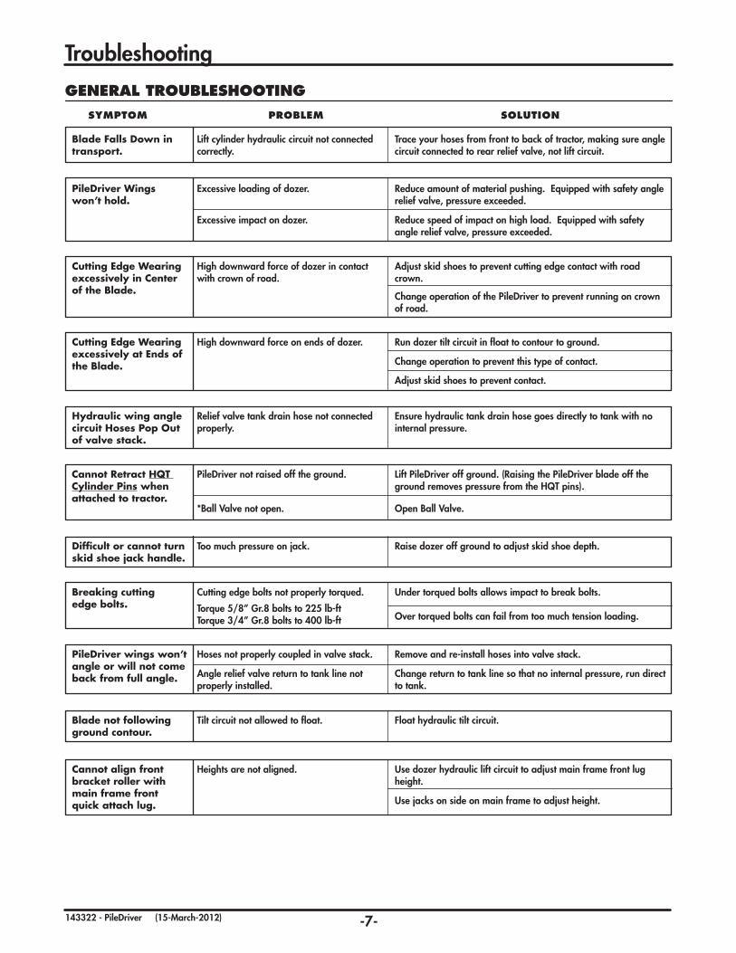
Troubleshooting
Blade Falls Down in transport.
Lift cylinder hydraulic circuit not connected correctly.
Trace your hoses from front to back of tractor, making sure angle circuit connected to rear relief valve, not lift circuit.
GENERAL TROUBLESHOOTING SYMPTOM PROBLEM SOLUTION
PileDriver Wingswon’t hold.
Excessive loading of dozer. Reduce amount of material pushing. Equipped with safety angle relief valve, pressure exceeded.
Excessive impact on dozer. Reduce speed of impact on high load. Equipped with safety angle relief valve, pressure exceeded.
Cutting Edge Wearing excessively in Center of the Blade.
High downward force of dozer in contact with crown of road.
Adjust skid shoes to prevent cutting edge contact with road crown.
Change operation of the PileDriver to prevent running on crown of road.
Cutting Edge Wearing excessively at Ends of the Blade.
High downward force on ends of dozer. Run dozer tilt circuit in float to contour to ground.
Change operation to prevent this type of contact.
Adjust skid shoes to prevent contact.
Hydraulic wing angle circuit Hoses Pop Out of valve stack.
Relief valve tank drain hose not connected properly.
Ensure hydraulic tank drain hose goes directly to tank with no internal pressure.
Cannot Retract HQT Cylinder Pins when attached to tractor.
PileDriver not raised off the ground. Lift PileDriver off ground. (Raising the PileDriver blade off the ground removes pressure from the HQT pins).
Difficult or cannot turn skid shoe jack handle.
Too much pressure on jack. Raise dozer off ground to adjust skid shoe depth.
Breaking cutting edge bolts.
Cutting edge bolts not properly torqued. Under torqued bolts allows impact to break bolts.
Over torqued bolts can fail from too much tension loading.Torque 5/8” Gr.8 bolts to 225 lb-ftTorque 3/4” Gr.8 bolts to 400 lb-ft
PileDriver wings won’t angle or will not come back from full angle.
Hoses not properly coupled in valve stack. Remove and re-install hoses into valve stack.
Angle relief valve return to tank line not properly installed.
Change return to tank line so that no internal pressure, run direct to tank.
Blade not following ground contour.
Tilt circuit not allowed to float. Float hydraulic tilt circuit.
Cannot align front bracket roller with main frame front quick attach lug.
Heights are not aligned. Use dozer hydraulic lift circuit to adjust main frame front lug height.
Use jacks on side on main frame to adjust height.
*Ball Valve not open. Open Ball Valve.

-8-143322 - PileDriver (15-March-2012)
Maintenance
GREASING
1. Use only a hand-held grease gun for all greasing.
2. Wipe grease fitting with a clean cloth before greasing, to avoid injecting dirt.
3. Replace and repair broken fittings immediately.
4. If fittings will not take grease, remove and clean thoroughly. Also clean lubricant passageway. Replace fitting if necessary.
5. Inject grease until you see grease being expelled from the pin or bushing areas.
Items to Grease Qty. Lift Cylinder Pins 2 per cylinder
Wing Cylinder Pins 2 per cylinder
Tilt Cylinder Pins 2 per cylinder
Tilt Ring 2 per side
Tilt Plate 2 per side
Tilt Bushing 1 per side
Side Bracket Pins 1 per side
Main Pivot Pins 1 per side
LUBE AFTER EVERY 8 HRS.MAINTENANCE SAFETY
1. Review the Operator’s Manual and all safety items before working with, maintaining or operating the machine.
2. Lower machine to ground, stop the tractor engine, place all controls in neutral, set park brake and remove ignition key before servicing, adjusting or repairing.
3. Clear the area of bystanders, especially children when carrying out any maintenance and repairs or making adjustments.
4. Place safety stands or large blocks under the frame before removing tires or working beneath the machine.
5. Be careful when working around or maintaining a high-pressure hydraulic system. Wear proper eye and hand protection when searching for a high pressure hydraulic leak. Use a piece of wood or cardboard as a backstop when searching for a pin hole leak in a hose or a fitting.
6. Always relieve pressure before disconnecting or working on hydraulic system.
Tilt Cylinder Pins
Tilt Bushing
Tilt Ring
Tilt Plate(Typical
both sides)
(Typical both sides)
(Typical both sides)
Wing Cylinder Pins(Typical both sides)
Lift Cylinder Pins
Main/Pivot Pins
Side Bracket Pins
(Typical both sides)
(Both sides)(Both sides)
Please note: The frame assemblies for your particular fit-up may differ significantly from those shown in the diagram, however, the basic grease points should be similar.
-9-143322 - PileDriver (15-March-2012)
Maintenance
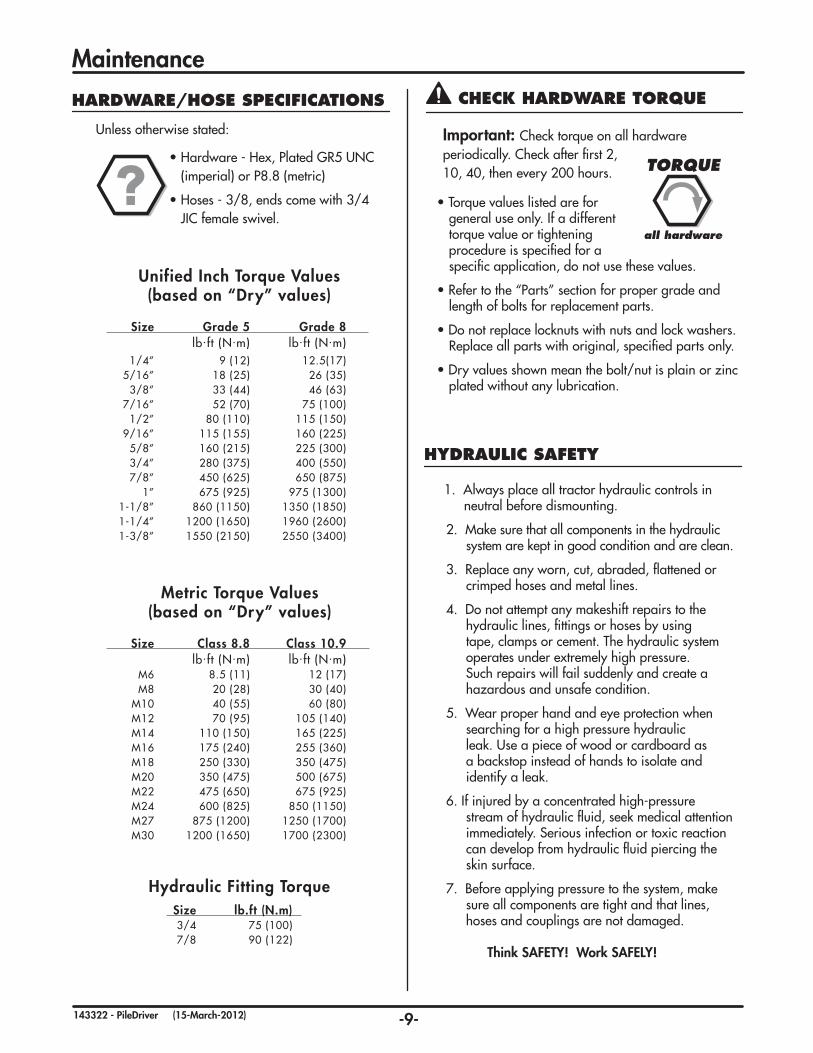
Metric Torque Values(based on “Dry” values)
Size Class 8.8 Class 10.9 lb.ft (N.m) lb.ft (N.m) M6 8.5 (11) 12 (17) M8 20 (28) 30 (40) M10 40 (55) 60 (80) M12 70 (95) 105 (140) M14 110 (150) 165 (225) M16 175 (240) 255 (360) M18 250 (330) 350 (475) M20 350 (475) 500 (675) M22 475 (650) 675 (925) M24 600 (825) 850 (1150) M27 875 (1200) 1250 (1700) M30 1200 (1650) 1700 (2300)
Unified Inch Torque Values(based on “Dry” values)
Size Grade 5 Grade 8 lb.ft (N.m) lb.ft (N.m) 1/4” 9 (12) 12.5(17) 5/16” 18 (25) 26 (35) 3/8” 33 (44) 46 (63) 7/16” 52 (70) 75 (100) 1/2” 80 (110) 115 (150) 9/16” 115 (155) 160 (225) 5/8” 160 (215) 225 (300) 3/4” 280 (375) 400 (550) 7/8” 450 (625) 650 (875) 1” 675 (925) 975 (1300) 1-1/8” 860 (1150) 1350 (1850) 1-1/4” 1200 (1650) 1960 (2600) 1-3/8” 1550 (2150) 2550 (3400)
HARDWARE/HOSE SPECIFICATIONS
Unless otherwise stated:
• Hardware - Hex, Plated GR5 UNC (imperial) or P8.8 (metric)
•Hoses-3/8,endscomewith3/4 JIC female swivel.
Important: Check torque on all hardware periodically. Check after first 2, 10, 40, then every 200 hours.
• Torque values listed are for general use only. If a different torque value or tightening procedure is specified for a specific application, do not use these values.
•Refer to the “Parts” section for proper grade and length of bolts for replacement parts.
•Do not replace locknuts with nuts and lock washers. Replace all parts with original, specified parts only.
•Dry values shown mean the bolt/nut is plain or zinc plated without any lubrication.
Hydraulic Fitting Torque Size lb.ft (N.m) 3/4 75 (100) 7/8 90 (122)
HYDRAULIC SAFETY
1. Always place all tractor hydraulic controls in neutral before dismounting.
2. Make sure that all components in the hydraulic system are kept in good condition and are clean.
3. Replace any worn, cut, abraded, flattened or crimped hoses and metal lines.
4. Do not attempt any makeshift repairs to the hydraulic lines, fittings or hoses by using tape, clamps or cement. The hydraulic system operates under extremely high pressure. Such repairs will fail suddenly and create a hazardous and unsafe condition.
5. Wear proper hand and eye protection when searching for a high pressure hydraulic leak. Use a piece of wood or cardboard as a backstop instead of hands to isolate and identify a leak.
6. If injured by a concentrated high-pressure stream of hydraulic fluid, seek medical attention immediately. Serious infection or toxic reaction can develop from hydraulic fluid piercing the skin surface.
7. Before applying pressure to the system, make sure all components are tight and that lines, hoses and couplings are not damaged.
Think SAFETY! Work SAFELY!
CHECK HARDWARE TORQUE
TORQUE
all hardware
-10-143322 - PileDriver (15-March-2012)
SAFETY DECALS
1. Keep safety decals and signs clean and legible at all times.
2. Replace safety decals and signs that are missing or have become illegible.
3. Replaced parts that displayed a safety sign should also display the current sign.
4. Safety decals or signs are available from your Dealer Parts Department. Safety decals will be available upon request.
How to Install Safety Decals:
• Be sure that the installation area is clean and dry.
• Decide on the exact position before you remove the backing paper.
• Remove the smallest portion of the split backing paper.
• Align the decal over the specified area and carefully press the small portion with the exposed sticky backing in place.
• Slowly peel back the remaining paper and carefully smooth the remaining portion of the decal in place.
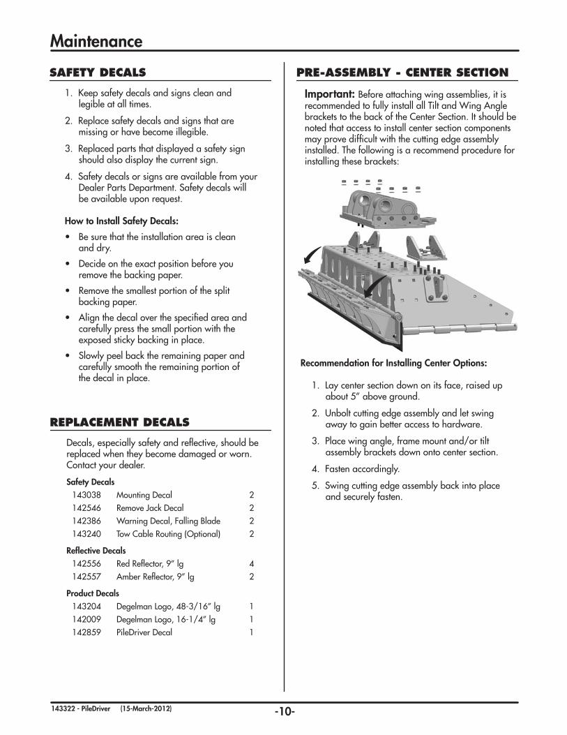
PRE-ASSEMBLY - CENTER SECTION
Important: Before attaching wing assemblies, it is recommended to fully install all Tilt and Wing Angle brackets to the back of the Center Section. It should be noted that access to install center section components may prove difficult with the cutting edge assembly installed. The following is a recommend procedure for installing these brackets:
Recommendation for Installing Center Options:
1. Lay center section down on its face, raised up about 5” above ground.
2. Unbolt cutting edge assembly and let swing away to gain better access to hardware.
3. Place wing angle, frame mount and/or tilt assembly brackets down onto center section.
4. Fasten accordingly.
5. Swing cutting edge assembly back into place and securely fasten.
REPLACEMENT DECALS
Decals, especially safety and reflective, should be replaced when they become damaged or worn. Contact your dealer.
Safety Decals143038 Mounting Decal 2142546 Remove Jack Decal 2142386 Warning Decal, Falling Blade 2143240 Tow Cable Routing (Optional) 2
Reflective Decals142556 Red Reflector, 9” lg 4142557 Amber Reflector, 9” lg 2
Product Decals143204 Degelman Logo, 48-3/16” lg 1142009 Degelman Logo, 16-1/4” lg 1142859 PileDriver Decal 1
Maintenance
-11-143322 - PileDriver (15-March-2012)
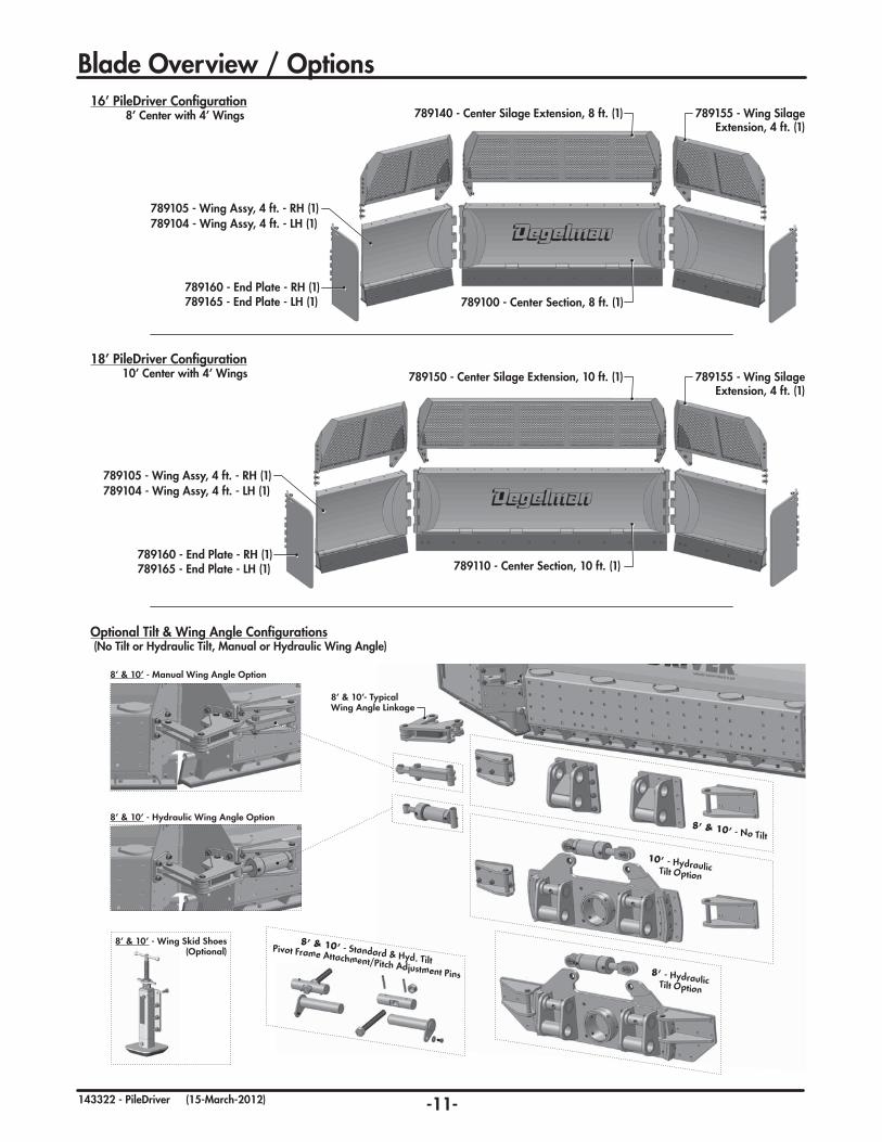
Blade Overview / Options16’ PileDriver Configuration
8’ Center with 4’ Wings
789105 - Wing Assy, 4 ft. - RH (1)
789100 - Center Section, 8 ft. (1)
789140 - Center Silage Extension, 8 ft. (1) 789155 - Wing Silage Extension, 4 ft. (1)
789104 - Wing Assy, 4 ft. - LH (1)
789160 - End Plate - RH (1)789165 - End Plate - LH (1)
18’ PileDriver Configuration10’ Center with 4’ Wings
789105 - Wing Assy, 4 ft. - RH (1)
789110 - Center Section, 10 ft. (1)
789150 - Center Silage Extension, 10 ft. (1) 789155 - Wing Silage Extension, 4 ft. (1)
789104 - Wing Assy, 4 ft. - LH (1)
789160 - End Plate - RH (1)789165 - End Plate - LH (1)
Optional Tilt & Wing Angle Configurations (No Tilt or Hydraulic Tilt, Manual or Hydraulic Wing Angle)
8’ & 10’ - No Tilt
10’ - Hydraulic Tilt Option
8’ - Hydraulic Tilt Option
8’ & 10’ - Manual Wing Angle Option
8’ & 10’- Typical Wing Angle Linkage
8’ & 10’ - Hydraulic Wing Angle Option
8’ & 10’ - Standard & Hyd. TiltPivot Frame Attachment/Pitch Adjustment Pins
8’ & 10’ - Wing Skid Shoes (Optional)

-12-143322 - PileDriver (07-December-2012)
Center Section Components
CENTER FRAME COMPONENTS (10’ or 8’)
118587 - Flat Washer, 1/2 F436 (30 or 24)
118587 - Flat Washer, 1/2 F436 (16)
789147 - Plate, Bolted - LH (1)789148 - Plate, Bolted - RH (1)(NOTE: Plate is positioned on INSIDE of
extension’s frame, and outside of center frame)
118009 - Bolt, 1/2 x 1-1/4 (15 or 12)
118292 - Bolt, 1/2 x 1-3/4 (8)
118043 - Bolt, 3/4 x 2 (6) 118405 - Nut, 1/2 (15 or 12)
118405 - Nut, 1/2 (8)
118504 - Lock Washer, 1/2 (15 or 12)
118772 - Lock Washer, 3/4 - GR8 (6)
118504 - Lock Washer, 1/2 (8)
118770 - Nut, 3/4 - GR8 (6)
TOP EXTENSION OPTION
CENTER SECTION ASSEMBLY
10’ Assembly: 789150 - Silage Extension, 10ft (1) - shown 8’ Assembly: 789140 - Silage Extension, 8ft (1)
10’ Assembly: 789110 - Center Section Assembly, 10ft (1) - shown 8’ Assembly: 789100 - Center Section Assembly, 8ft (1)
(8’ Center Top Extension Option)
(8’ Center Section Assembly)
117438 - Bolt, Carriage 3/4 x 2-1/2 GR8 (8)
118005 - Bolt, 3/8 x 1 (18 or 12)
118670 - Bolt, 3/8 x 2-1/2 GR8 (2)
810279 - Retaining Ring, 1-1/4 Internal (2) 788596 - Shaft Pin, 10ft (1) - shown
788602 - Shaft Pin, Wing (2)
788594 - Shaft Pin, 8ft (1)
788608 - Lug, Stop (2)
788541 - Center Assy, 10ft (1) - shown789124 - Cap, Plate (9 or 6)788537 - Center Assy, 8ft (1)
118775 - Flat Washer, 3/4
F436 (8)
118503 - Lock Washer, 3/8 (18 or 12)
117414 - Lock Nut, 3/4
unitorque (8)
118417 - Lock Nut, 3/8 (2)
118203 - Bolt, Scraper 5/8 x 2 (12 or 10)
118203 - Bolt, Scraper 5/8 x 2 (13 or 11)
116295 - Cutting Edge, 5/8 x 8 - 10’ (1) - shown
789125 - Cutting Edge Holder, 10’ (shown) (1)789115 - Cutting Edge
Holder, 8’ (1)
116292 - Cutting Edge, 3/4 x 5 - 10’ (1) - shown
116294 - Cutting Edge, 5/8 x 8 - 8’ (1)
116291 - Cutting Edge, 3/4 x 5 - 8’ (1)
118772 - Lock Washer, 3/4 - GR8 (10 or 8)
118508 - Lock Washer, 5/8 (13 or 11)
118447 - Lock Nut, 5/8 - unitorque (12 or 10) 118770 - Nut, 3/4
- GR8 (10 or 8)
117438 - Bolt, Carriage 3/4 x 2-1/2 GR8 (10 or 8)
789129 - Bolt Holder Bar, 1/2 (5 or 4)
118407 - Nut, 5/8 (13 or 11)

-13-143322 - PileDriver (15-March-2012)
Wing Section Components
WING FRAME COMPONENTS (RH Shown)
TOP EXTENSION OPTION
WING SECTION ASSEMBLY
RH & LH: 789155 - Silage Extension, 4ft (1)
117438 - Bolt, Carriage 3/4 x 2-1/2 GR8 (8)
118051 - Bolt, 3/4 x 3 GR8 (3)
118772 - Lock Washer, 3/4 - GR8 (11)
118770 - Nut, 3/4 - GR8 (11)
END PLATE ASSEMBLY RH Assembly: 789160 - End Plate Assembly (1) - shown
LH Assembly: 789165 - End Plate Assembly (1)
118587 - Flat Washer, 1/2 F436 (12)
118587 - Flat Washer, 1/2 F436 (16)
789147 - Plate, Bolted - LH (1)789148 - Plate, Bolted - RH (1)(NOTE: Plate is positioned on INSIDE of
extension’s frame, and outside of wing frame)
118009 - Bolt, 1/2 x 1-1/4 (6)
118292 - Bolt, 1/2 x 1-3/4 (8)
118043 - Bolt, 3/4 x 2 (6)
118405 - Nut, 1/2 (6)
118405 - Nut, 1/2 (8)
118504 - Lock Washer, 1/2 (6)
118772 - Lock Washer, 3/4 - GR8 (6)
118504 - Lock Washer, 1/2 (8)
118770 - Nut, 3/4 - GR8 (6)
OPTIONAL SKID SHOE788696 - Skid Shoe
Assembly (1) (comes with hardware)
Optional Skid Shoe Assembly
RH Assembly: 789105 - Wing Section Assembly, 4ft (1) - shown LH Assembly: 789104 - Wing Section Assembly, 4ft (1)
117438 - Bolt, Carriage 3/4 x 2-1/2 GR8 (4)
118005 - Bolt, 3/8 x 1 (6)
810279 - Retaining Ring, 1-1/4 Internal (2)
788590 - Shaft Pin, 4ft (1)
788608 - Lug, Stop (1)
788556 - Wing Assy, RH 4ft (1) - shown
789135 - Cap, Plate - Jack Bushing (1)
788557 - Wing Assy, LH 4ft (1)
118775 - Flat Washer, 3/4 F436 (4)
118503 - Lock Washer, 3/8 (6)
117414 - Lock Nut, 3/4 unitorque (4)
118772 - Lock Washer, 3/4 - GR8 (4)
118770 - Nut, 3/4 - GR8 (4)
789130 - Cutting Edge Holder, 4’ (1)
117438 - Bolt, Carriage 3/4 x 2-1/2 GR8 (4)
789129 - Bolt Bar, 1/2 (2)
118203 - Bolt, Scraper 5/8 x 2 (5)
118203 - Bolt, Scraper 5/8 x 2 (6)
116293 - Cutting Edge, 3/4 x 5 - 4’ (1)118508 - Lock Washer, 5/8 (5)
118407 - Nut, 5/8 (5)
116296 - Cutting Edge, 5/8 x 8 - 4’ (1)
118447 - Lock Nut, 5/8 - unitorque (6)
789124 - Cap, Plate (2)(One located under Cutting Edge Holder - see below)

-14-143322 - PileDriver (15-March-2012)
Tilt Frame Components - 8’ & 10’
HYDRAULIC TILT FRAME COMPONENTS
TILT FRAME ASSEMBLY COMPONENTS (10’)
TILT FRAME ASSEMBLY COMPONENTS (8’)
10’ Assembly: 789250 - Tilt Assembly, Hydraulic - 10ft (1)
8’ Assembly: 789170 - Tilt Assembly, Hydraulic - 8ft (1)
117414 - Lock Nut, 3/4 - unitorque (8)
118420 - Lock Nut, 1/2 - unitorque (4)118292 - Bolt, 1/2 x 1-3/4 (4)
789196 - Tilt Plate, Inner Ring (2)
789175 - Tilt, Pivot Base Assembly (1)
789255 - Tilt, Blade Base Assembly - 10ft (1)
789195 - Bushing, Tilt Ring (1)
117145 - Bushing, 1-7/8 x 1-1/2 (1)
117145 - Bushing, 1-7/8 x 1-1/2 (1)
118051 - Bolt, 3/4 x 3, GR8 (8)
789212 - Threaded Adjustment Pin (2)
117519 - Roll Pin, 1/2 x 4 (4)
118336 - Grease Fitting, 1/4-28 (10)
118337 - Plastic Cap (10)
118203 - Bolt, Scraper 5/8 x 2 (9)118508 - Lock Washer, 5/8 (9)118407 - Nut, 5/8 (9)
118537 - Flat Washer, 5/8 F436 (9)
118770 - Nut, 3/4 - GR8 (6)
118772 - Lock Washer, 3/4 - GR8 (8)
117437 - Bolt, Carriage 3/4 x 2 GR8 (8)
117414 - Lock Nut, 3/4 - unitorque (8)
118420 - Lock Nut, 1/2 - unitorque (4)118292 - Bolt, 1/2 x 1-3/4 (4)
789196 - Tilt Plate, Inner Ring (2)
789175 - Tilt, Pivot Base Assembly (1)
789185 - Tilt, Blade Base Assembly - 8ft (1)
789195 - Bushing, Tilt Ring (1)
117145 - Bushing, 1-7/8 x 1-1/2 (1)
117145 - Bushing, 1-7/8 x 1-1/2 (1)
117129 - Bushing, 1-1/2 x 3/4 (4)
118051 - Bolt, 3/4 x 3, GR8 (8)
789212 - Threaded Adjustment Pin (2)
117519 - Roll Pin, 1/2 x 4 (4)
118336 - Grease Fitting, 1/4-28 (10)
118337 - Plastic Cap (10)
118203 - Bolt, Scraper 5/8 x 2 (9) 118508 - Lock Washer, 5/8 (9)118407 - Nut, 5/8 (9)
118537 - Flat Washer, 5/8 F436 (9)
118770 - Nut, 3/4 - GR8 (20)
118772 - Lock Washer, 3/4 - GR8 (20)
117437 - Bolt, Carriage 3/4 x 2 GR8 (20)

-15-143322 - PileDriver (15-March-2012)
Pivot Frame Mounting/Wing Angle Components - 8’ & 10’
STANDARD FRAME MOUNT BRACKETS (No Tilt - 8’ & 10’)
789201 - Pitch Pivot Base Assembly (2)
788624 - Wing Linkage Bracket (2)
117129 - Bushing, 1-1/2 x 3/4 (typ)
810280 - Retaining Ring, 1-1/4 External (4)117442 - Flat Washer, 1-1/4 (4)
788600 - Pin, 8-1/2 (2)
117437 - Bolt, Carriage 3/4 x 2 GR8 (20)
117437 - Bolt, Carriage 3/4 x 2 GR8 (12)
118775 - Flat Washer, 3/4 F436 (20)
118775 - Flat Washer, 3/4 F436 (12)
117414 - Lock Nut, 3/4 unitorque (20)
117414 - Lock Nut, 3/4 - unitorque (12)
789212 - Threaded Adjustment Pin (2)
117519 - Roll Pin, 1/2 x 4 (4)
WING ANGLE LINKAGE COMPONENTS (Typical)
PIVOT FRAME PITCH ADJUSTMENT PINS
LH LINKAGE (Assembled)
810280 - Retaining Ring, 1-1/4 External (16)
788613 - Linkage Assembly, 3 Hole (2)
788619 - Linkbar Assembly (2)
117442 - Flat Washer, 1-1/4 (16)
788599 - Pin, 5-1/8 (6)
788598 - Pin, 3-5/8 (2)
117129 - Bushing, 1-1/2 x 3/4 (typ)
789213 - Pitch Adjustment Pin (2)
789320 - Pitch Pivot Pin (2)
117519 - Roll Pin, 1/2 x 4 (4)
789210 - Pitch Adjustment Threaded
Rod Assembly (2)
118647 - Nut, 1-1/2 (2)
118514 - Flat Washer, 5/8 (2)
118645- Bolt, 5/8 x 1-1/4 (2)118508 - Lock Washer, 5/8 (2)
RH LINKAGE (exploded)
-16-143322 - PileDriver (12-February-2013)
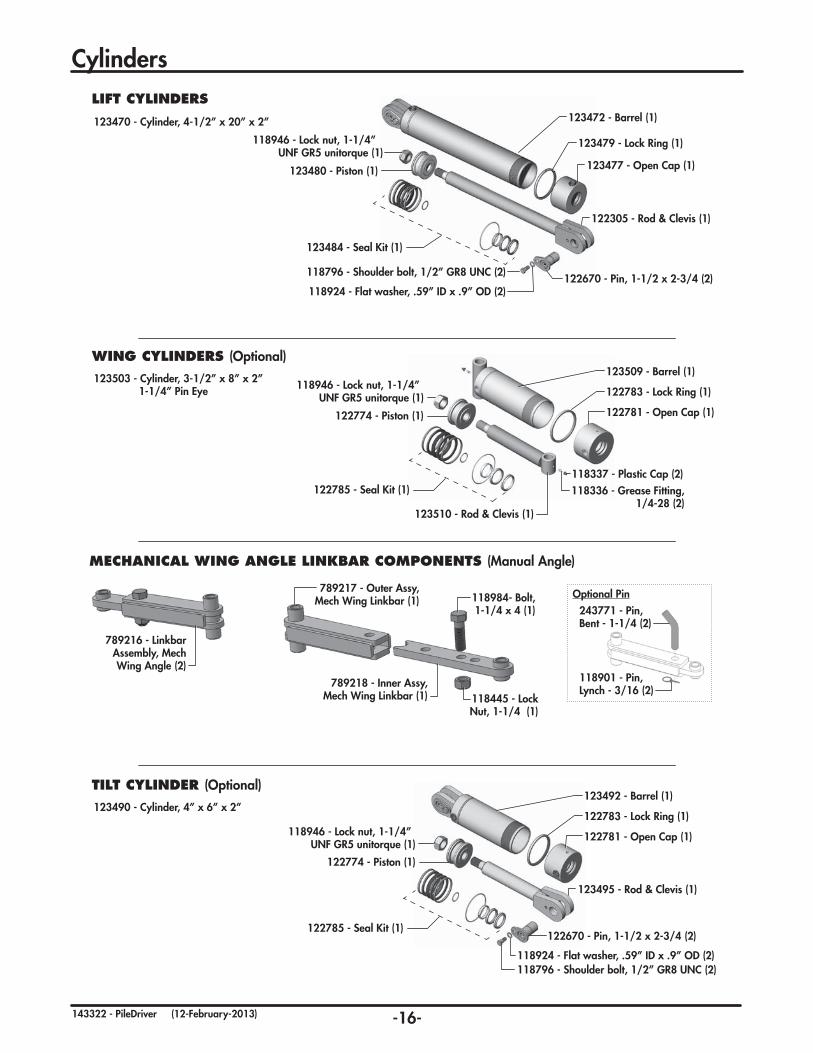
Cylinders
TILT CYLINDER (Optional)
123490 - Cylinder, 4” x 6” x 2” 123492 - Barrel (1)
122783 - Lock Ring (1)
122781 - Open Cap (1)
123495 - Rod & Clevis (1)
122774 - Piston (1)
122670 - Pin, 1-1/2 x 2-3/4 (2)122785 - Seal Kit (1)
118946 - Lock nut, 1-1/4” UNF GR5 unitorque (1)
118796 - Shoulder bolt, 1/2” GR8 UNC (2)118924 - Flat washer, .59” ID x .9” OD (2)
LIFT CYLINDERS
123470 - Cylinder, 4-1/2” x 20” x 2” 123472 - Barrel (1)
118796 - Shoulder bolt, 1/2” GR8 UNC (2)
118924 - Flat washer, .59” ID x .9” OD (2)
123480 - Piston (1)
123479 - Lock Ring (1)
123477 - Open Cap (1)
122305 - Rod & Clevis (1)
118946 - Lock nut, 1-1/4” UNF GR5 unitorque (1)
122670 - Pin, 1-1/2 x 2-3/4 (2)
123484 - Seal Kit (1)
MECHANICAL WING ANGLE LINKBAR COMPONENTS (Manual Angle)
789216 - Linkbar Assembly, Mech Wing Angle (2)
789217 - Outer Assy, Mech Wing Linkbar (1)
789218 - Inner Assy, Mech Wing Linkbar (1)
118984- Bolt, 1-1/4 x 4 (1)
118445 - Lock Nut, 1-1/4 (1)
243771 - Pin, Bent - 1-1/4 (2)
118901 - Pin, Lynch - 3/16 (2)
Optional Pin
WING CYLINDERS (Optional)
123503 - Cylinder, 3-1/2” x 8” x 2” 1-1/4” Pin Eye
123509 - Barrel (1)
122783 - Lock Ring (1)
122781 - Open Cap (1)
123510 - Rod & Clevis (1)
122774 - Piston (1)
122785 - Seal Kit (1)
118946 - Lock nut, 1-1/4” UNF GR5 unitorque (1)
118336 - Grease Fitting, 1/4-28 (2)
118337 - Plastic Cap (2)
-17-143322 - PileDriver (15-March-2012)
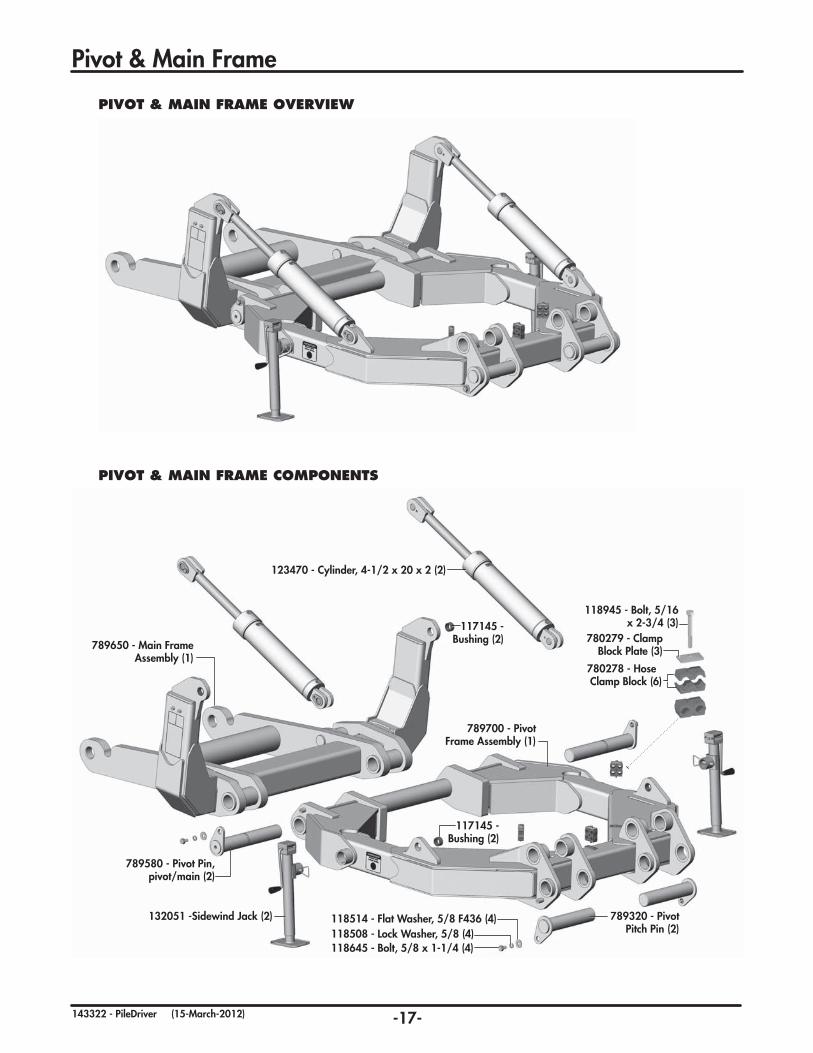
Pivot & Main Frame
PIVOT & MAIN FRAME OVERVIEW
PIVOT & MAIN FRAME COMPONENTS
118645 - Bolt, 5/8 x 1-1/4 (4)118508 - Lock Washer, 5/8 (4)118514 - Flat Washer, 5/8 F436 (4)
789580 - Pivot Pin, pivot/main (2)
117145 - Bushing (2)
117145 - Bushing (2)
789700 - Pivot Frame Assembly (1)
132051 -Sidewind Jack (2)
789650 - Main Frame Assembly (1)
789320 - Pivot Pitch Pin (2)
780278 - Hose Clamp Block (6)
780279 - Clamp Block Plate (3)
118945 - Bolt, 5/16 x 2-3/4 (3)
123470 - Cylinder, 4-1/2 x 20 x 2 (2)
-18-143322 - PileDriver (15-March-2012)
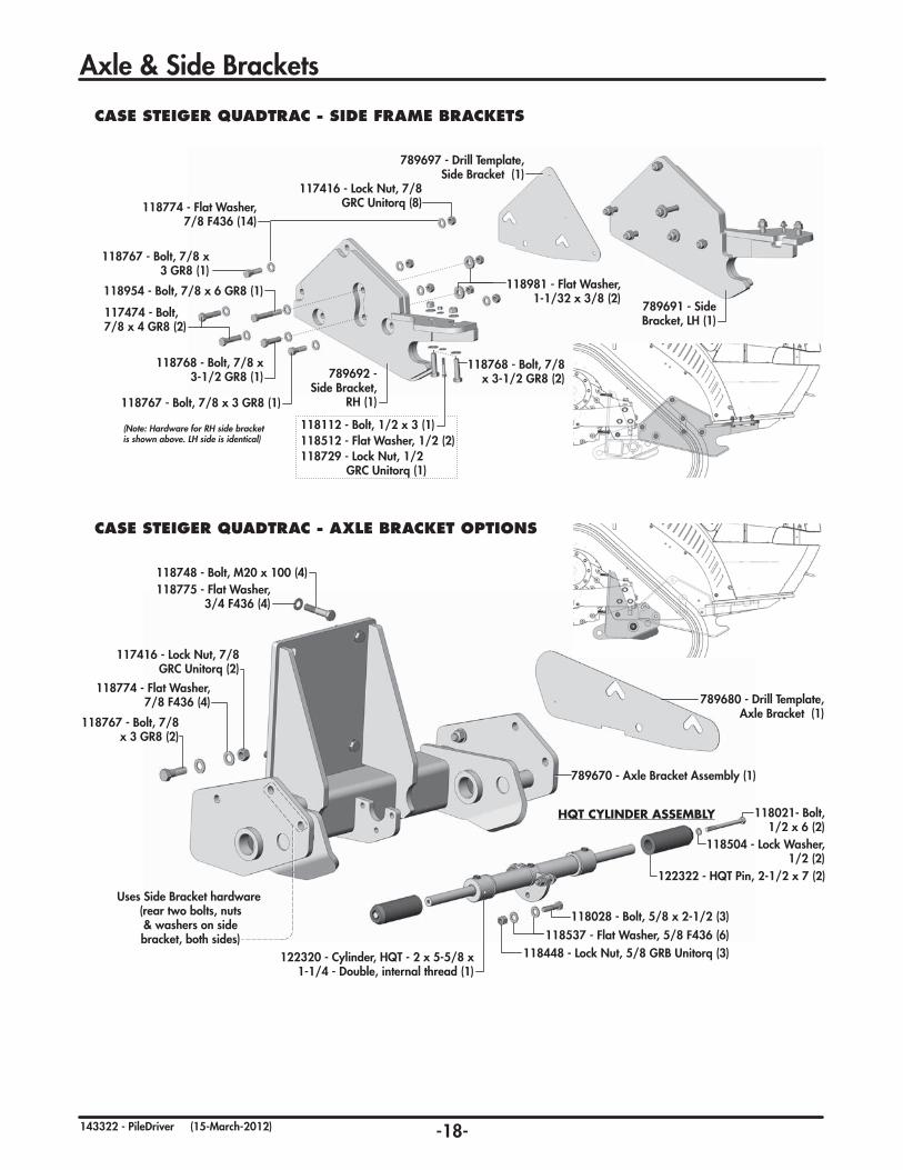
CASE STEIGER QUADTRAC - AXLE BRACKET OPTIONS
118774 - Flat Washer, 7/8 F436 (4)
118767 - Bolt, 7/8 x 3 GR8 (2)
117416 - Lock Nut, 7/8 GRC Unitorq (2)
HQT CYLINDER ASSEMBLY
789680 - Drill Template, Axle Bracket (1)
Uses Side Bracket hardware (rear two bolts, nuts & washers on side bracket, both sides)
118775 - Flat Washer, 3/4 F436 (4)
118748 - Bolt, M20 x 100 (4)
118028 - Bolt, 5/8 x 2-1/2 (3)
118021- Bolt, 1/2 x 6 (2)
118448 - Lock Nut, 5/8 GRB Unitorq (3)
122322 - HQT Pin, 2-1/2 x 7 (2)
118504 - Lock Washer, 1/2 (2)
118537 - Flat Washer, 5/8 F436 (6)
122320 - Cylinder, HQT - 2 x 5-5/8 x 1-1/4 - Double, internal thread (1)
789670 - Axle Bracket Assembly (1)
Axle & Side Brackets
CASE STEIGER QUADTRAC - SIDE FRAME BRACKETS
118774 - Flat Washer, 7/8 F436 (14)
118981 - Flat Washer, 1-1/32 x 3/8 (2)
117474 - Bolt, 7/8 x 4 GR8 (2)
118954 - Bolt, 7/8 x 6 GR8 (1)
118767 - Bolt, 7/8 x 3 GR8 (1)
118767 - Bolt, 7/8 x 3 GR8 (1)
118768 - Bolt, 7/8 x 3-1/2 GR8 (2)
118768 - Bolt, 7/8 x 3-1/2 GR8 (1)
117416 - Lock Nut, 7/8 GRC Unitorq (8)
789691 - Side Bracket, LH (1)
789697 - Drill Template, Side Bracket (1)
789692 - Side Bracket,
RH (1)
(Note: Hardware for RH side bracket is shown above. LH side is identical) 118512 - Flat Washer, 1/2 (2)
118112 - Bolt, 1/2 x 3 (1)
118729 - Lock Nut, 1/2GRC Unitorq (1)

-19-143322 - PileDriver (15-March-2012)
Axle & Side Bracket Installation
IMPORTANT-TORQUETorque all bolts properly!Refer to maintenance section for torque specifications.
CASE STEIGER QUADTRAC
A Preparation: Remove front weights and toolboxes. (if applicable, remove tow cable brackets on front axle housing and front weight bar, some components will be re-installed with this fit-up).
B In order to drill new holes for brackets, it is necessary to rotate the front track forward. This can be accomplished by backing over a secure ramp resulting in the rear of the track being raised approximately
12 inches. (Note: Some models require a rubber bumper to be removed before rotating the track this amount. These bumpers need to be re-installed after bracket installation.)
C Mount the Side Template over the 2 existing chain loop slots and 1 existing hole using new side bracket mounting hardware. IMPORTANT: Ensure bottom of template is parallel with bottom of frame!
Center punch 2 top location holes through templates to scribe points and note bottom front hole to be enlarged. Remove template. Drill out 2 scribed holes (C1 & C2) and one existing hole (C3) to 15/16”. (Repeat step C on opposite side)
Note: If second scribed hole (C2) is unable to be drilled from outside, even with track fully rotated, it can be drilled from the inside frame - concentric (centered) to forward chain loop radius as shown.
D On inside of frame, mount the Axle Template over the 2 existing chain loop slots and 1 existing hole using new side bracket mounting hardware. IMPORTANT: Ensure bottom of template is parallel with bottom of frame!
Center punch this rear location hole through template to scribe points. Remove template. Drill out scribed hole (D1) to 15/16”.
(Repeat step D on opposite side)
E “Loosely” install the axle bracket with the 4 front face M20 x 100 bolts and the rear 7/8” x 3” bolts on the side frame (one per side).
F Position Side Brackets with the supplied 7/8” bolts (various lengths) and hardware. Note location of two heavy washers on inside frame at chain loops. Install 1/2” bolt and hardware. Tighten bolts except for the two 4” axle bracket bolts should remain loose for now.
G Tighten the axle bracket bolts in the following order: 1) Tighten the 4 front face bolts (E-M20x100). 2) Tighten the 6 rear side bracket bolts (E-3” & F-4”).
E-M20x100
E-3”
A
Remove Weight Stack & Toolboxes
A
Remove Axle Tow Cable Bracket & Front Tow
Cable Hanger bracket (if applicable) A
Remove Front Track Rear Rubber Bumper (if applicable)
A12”
B
B
B
CC1
C2
C3
(Ensure parallel)
(Scribe & Drill)
(Enlarge)
Side Template C2
C3
D
(Scribe & Drill)
Template positioned on inside of frame - see photo
Axle Template
C2
D1
D1(Ensure parallel)
Optional Drill location for C2 Inside frame concentric to forward chain loop radius.
D
12”
F-3-1/2”
1/2” x 3”
F-3-1/2”
F-3”F-6”
F-3”
F-4”
E-M20x100
E-M20x100E-3”
E-3”
Heavy Flat WashersUsed on inside
Chain loop locations(2 per side)
Standard Flat WashersUsed all other locations
F-4”F-4”
F-3-1/2”
F-6”
F-3” F-3”
F-3-1/2” F-3-1/2”F-4”
F-4”
F-4”
F-4”
F-6” F-6”
E-3”E-3”

-20-143322 - PileDriver (15-March-2012)
Hydraulic Coupler, Ball Valve & Tow Brackets
Hydraulic Coupler & Ball Valve Components
Tow Cable Bracket
(*For models with existing tow cable option) FRONT TOW CABLE HOLDER BRACKET*
117548 - Bolt, M24 x 3 x 70 (1)
Re-use the existing tow cable holder components and hardware from
the removed front weight bar bracket.
118259 - Bolt, M12 x 1.75 x 70 (2)
789762 - Tow Cable Bracket (1)
Re-attach tow cable support hook to axle bracket lug.
(if applicable)
HYDRAULIC & COUPLER MOUNTING BRACKETS
141504 - 90° Elbow, 3/4 JIC-m x ORB (1)141518 - 90° Elbow, 3/4 JIC-m x JIC-f (1) 789722 - Hydraulic
Coupler Bracket (1)
789720 - Hydraulic Mount Bracket (1)
789724 - Ball Valve Bracket (1)
118734 - Bolt, M10 x 50 (2)
118536 - Flat Washer, 7/16 (2)117464 - Lock Washer, M10 (2)
118504 - Lock Washer, 1/2 (2)
118731 - Flat Washer, 5/16 (4)
118587 - Flat Washer, 1/2 F436 (4)
118731 - Flat Washer, 5/16 (8)
118718 - Lock Nut, 5/16 (4)
118718 - Lock Nut, 5/16 (4)
118405 - Nut, 1/2 (2)
117489 - U Bolt, 5/16 (2)
141515 - Nipple, 3/4 JIC-m x ORB (1)
141597 - Ball Valve, 3/4 ORB (1)
780332 - Hose Clamp Block, 1/2 (4)
118014 - Bolt, 1/2 x 2 (2)
117544 - Bolt, 5/16 x 3-1/2 (1)
118110 - Bolt, 5/16 x 1 (4)
780333 - Clamp Block Plate (2)

-21-143322 - PileDriver (08-May-2012)
Hydraulic Routing
141527 - Tee 3/4 JIC-m x JIC-m x ORB
248385 - Plug, Kinecor
141501- Tee 3/4JIC-m
141518 - 90° Elbow3/4 JIC-m x JIC-f
141504 - 90° Elbow3/4 m JIC x ORB
141515 - Connector3/4 m JIC x ORB
141675 - Flush Face Quick Coupler -f
141577 - Dust CapCoupler-m
141618 - Nipple, 3/4 JIC x 1-1/16 ORB
141674 - Flush Face Quick Coupler -m
141068- Relief Valve
1 2 3
141581 - Quick Coupler-m - 3/4 ORB
13
9 10
4 6
14 1615
5
7 8
17
COMMON HYDRAULIC FITTINGS
This is a quick visual reference of the most common hydraulic fittings used in PileDriver dozer blade hydraulic systems. The icon and numbers are used for reference in the routing diagrams on the following pages. Please note, this particular fit-up may not use all fitting types shown in the reference chart below.
117546 - Star Washer
117545 - Jam Nut 3/4
11
141560 - 90° Elbow, 3/4 JIC-m x 9/16 ORB
141561 - Nipple, 3/4 JIC-m x 9/16 ORB
141573 - Flush Face Coupler, 3/4 ORB
141620 - 45° Elbow3/4 JIC-m x f-sw
12

-22-143322 - PileDriver (03-May-2012)
Hydraulic Routing
TILT CYLINDER ROUTING123490 - Cylinder, 4 x 6 x 2 (1)
169
156
126572 - Hose, 1/2 x 169 (1)
126571 - Hose, 1/2 x 156 (1)
4 141504 - 90° Elbow, 3/4 JIC-m x ORB (2)
LIFT CYLINDERS ROUTING123470 - Cylinder, 4-1/2 x 20 x 2 (2)
4 141504 - 90° Elbow, 3/4 JIC-m x ORB (2)
3 141518 - 90° Elbow, 3/4 JIC-m x JIC-f (2)
2 141527 - Tee 3/4 JIC-m x JIC-m x ORB (2)
126561 - Hose, 1/2 x 82 (1)82
126691 - Hose, 1/2 x 96 (1)96
126 126566 - Hose, 1/2 x 126 (1)
126566 - Hose, 1/2 x 75 (1)75
444 4
132
144
183 174
144
156
198 183
Refer to Front Hydraulic Connection Detail for connection options.
169
156
4
4
Refer to Front Hydraulic Connection Detail for connection options.
WING ANGLE CYLINDERS ROUTING123503 - Cylinder, 3-1/2 x 8 x 2 (2)
144
156
183
198
126563 - Hose, 1/2 x 144 (1)
126571 - Hose, 1/2 x 156 (1)
126567 - Hose, 1/2 x 183 (1)
126555 - Hose, 1/2 x 198 (1)
132
144
174
183
126511 - Hose, 1/2 x 132 (1)
126563 - Hose, 1/2 x 144 (1)
126600 - Hose, 1/2 x 174 (1)
126567 - Hose, 1/2 x 183 (1)
4 141504 - 90° Elbow, 3/4 JIC-m x ORB (4)
Models with 8ft Center Section
Models with 10ft Center Section
4 3 2
4 3 2
96
82Ports Face Up
Refer to Front Hydraulic Connection Detail for connection options.
75
126

-23-143322 - PileDriver (15-March-2012)
Hydraulic Routing
FROM FRONT CYLINDER HOSE ROUTING FRONT HYDRAULIC CONNECTION DETAIL
8
9
10
11
141674 - Flush Face Quick Coupler-m (2-8)
141675 - Flush Face Quick Coupler-f (2-8)
141618 - Nipple, 3/4 JIC-m x 1-1/16 ORB (2-8)
117546 - Star Washer (2-8)
117545 - Jam Nut 3/4 (2-8)
7
Hydraulic Lift Only
Hydraulic Lift & Wings
Hydraulic Lift & Tilt
Hyd. Lift, Tilt, & Wings
144
311
All (311) Hoses Route To Rear Connection
311
144
311311
311311
From Front Cylinders
To Rear Connection
9
From Lift Cylinders
From Wing Cylinders(10ft Center Section)
From Wing Cylinders(8ft Center Section)
From Tilt Cylinders Front of Tractor
Front RH Side Bracket
78
1110789722 - Hydraulic
Coupler Mount
156
96
144
132
183
174
169
126
156
144
198
183
Hoses from front cylinders are wrapped together in a
large protective hose wrap.
Tilt CylindersLift Cylinders
Wing Angle Cylinders
311
311
311
311
311
311
311
311
Refer to Ball Valve/ HQT Cylinder Routing
on next page.
-24-143322 - PileDriver (11-March-2013)
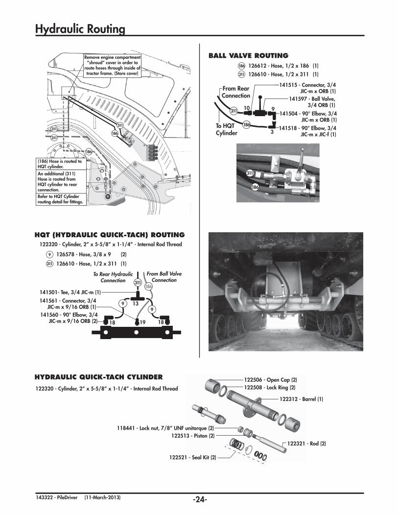
Hydraulic Routing
HQT (HYDRAULIC QUICK-TACH) ROUTING
126578 - Hose, 3/8 x 9 (2)
311
9
126610 - Hose, 1/2 x 311 (1)
To Rear Hydraulic Connection
19
1399
From Ball Valve Connection
18 18
311186
141501- Tee, 3/4 JIC-m (1)
141560 - 90° Elbow, 3/4 JIC-m x 9/16 ORB (2)
141561 - Connector, 3/4 JIC-m x 9/16 ORB (1)
122320 - Cylinder, 2” x 5-5/8” x 1-1/4” - Internal Rod Thread
BALL VALVE ROUTING
From Rear Connection
To HQT Cylinder
9
3
10
186
141504 - 90° Elbow, 3/4 JIC-m x ORB (1)
141518 - 90° Elbow, 3/4 JIC-m x JIC-f (1)
141515 - Connector, 3/4 JIC-m x ORB (1)
141597 - Ball Valve, 3/4 ORB (1)
186
311
126612 - Hose, 1/2 x 186 (1)311
186
126610 - Hose, 1/2 x 311 (1)
311
Remove engine compartment “shroud” cover in order to
route hoses through inside of tractor frame. (Store cover)
311
186
186
311
311
(186) Hose is routed to HQT cylinder.
An additional (311) Hose is routed from HQT cylinder to rear connection.Refer to HQT Cylinder routing detail for fittings.
HYDRAULIC QUICK-TACH CYLINDER
122320 - Cylinder, 2” x 5-5/8” x 1-1/4” - Internal Rod Thread
122321 - Rod (2)
122521 - Seal Kit (2)
122513 - Piston (2)118441 - Lock nut, 7/8” UNF unitorque (2)
122312 - Barrel (1)
122508 - Lock Ring (2)122506 - Open Cap (2)

-25-143322 - PileDriver (08-May-2012)
Hydraulic Routing
REAR HOSE ROUTING DETAIL
RELIEF VALVE COMPONENTS(HYD. WING ANGLE OPTION)
180
- Tank Line Locatedon LH Side in front of
main articulation point. - Remove existing
ORFS Cap.
- Attach 1/2” Dump Line (180) to ORFS fitting and route hose
back to rear relief valve.
RELIEF VALVE DUMP LINE CONNECTION
IMPORTANT
Relief valveMUST
be used onWing AngleHyd System
MUST be zero pressure in return line.
IMPORTANT
WING ANGLESYSTEM ONLYHoses from wing angle cylinders must connect to rear relief valve system. Tank drain line (180) must also be properly installed.
9 4 11
311
311
311
311
311
311
311
9 9
Connect direct to rear hydraulic
connections.
TILT HOSES (2) LIFT HOSES (2)
HQT CYLINDER HOSES (2)
Connect to tractor’s hydraulic tank drain line
located on inside of frame.
WING HOSES (4) route to relief valve
WING HOSES (4) from relief valve
Refer to Front Hydraulic Connection Details
- Ensure there is enough slack for turning. - Ensure hoses are secured away from “Pinch
Hazards” such as pivot or oscillation stop blocks.- Secure the hoses so they do not rub the driveline.
IMPORTANT
OSCILLATION POINTRoute Hoses above or below this area to avoid pinching
BOTTOM
9
99
99
1
9
9
9
6
311
311
311
311
180
36
36
36
36
118503 - Lock Washer, 3/8 (4)118511 - Flat Washer, 3/8 (4)
118403 - Nut, 3/8 (4)
118673 - Bolt, 3/8 x 5 (4)
141504 - 90° Elbow, 3/4 JIC-m x ORB (8)
789725 - Relief Valve Bracket (1)
141068 - Relief Valve (1)
Re-use Existing Hardware to mount
141515 - Connector, 3/4 m JIC x ORB (1)
248385 - Plug, Kinecor (4)
Relief Valve MUST be used on Wing Angle Hydraulic System IMPORTANT
311 126610 - Hose, 1/2 x 311 (2 - 8)
9 141504 - 90° Elbow, 3/4 JIC-m x ORB (4 -18)
4
11
141581 - Quick Coupler-m - 3/4 ORB (4 -10)
141577 - Dust Cap Coupler-m (4 -10)
All Models - (quantity depends on options)
126570 - Hose, 1/2 x 36 (4)
126688 - Hose, 1/2 x 180 (1)(3/4 JIC F-SW, 10 ORFS EL)
180
36
6 141515 - Connector, 3/4 JIC-m x ORB (1)
18
1 141068 - Relief Valve (1)
248385 - Plug, Kinecor (4)
Hydraulic Wing Angle Models - (also require:)
311
311
311
311
311
311
311
311
311
186
186

-26-143322 - PileDriver (15-March-2012)
Mounting
10 STEP MOUNTING PROCEDURE
Procedure to mount blade:
1. Align the tractor behind the main frame. (Unhook & lower front Tow Cable - if applicable) 2. Open the HQT (Hydraulic Quick-Tach) circuit ball
valve. Check and ensure HQT Cylinder pins are retracted.
3. Drive forward close enough to connect the hydraulics. Hook up the hydraulics.
4. Extend the lift cylinders fully. 5. Jack up frame until the main frame “roller pins” are
lifted up level with the side bracket hooks. 6. Drive forward to engage the side bracket hooks. 7. Lower roller pins onto side bracket hooks with jacks
until the jack base(s) are approximately 4” to 6” off the ground.
8. Retract the lift cylinders bringing the rear main frame connection into position. (By retracting the lift cylinder, the weight of the front of the blade swings the back frame upward, positioning the HQT Cylinder pins)
9. Activate the HQT Cylinder and ensure both axle pins are engaged and fully secured.
IMPORTANT: Close the ball valve to prevent accidental operation of this circuit.
10. Remove frame jacks and place in their storage positions on back of blade. (Re-attach front Tow Cable on front bracket hook - if applicable)
IMPORTANT: You must retract the lift cylinders to lift blade before disengaging the HQT (Hydraulic Quick-Tach) cylinder pins! This transfers the weight to the side bracket hooks from the rear axle. Otherwise, the whole assembly may come crashing down.
Procedure to remove blade:
1. Retract lift cylinder to lift blade.
2. Open the HQT circuit Ball Valve. Activate the HQT Cylinder to Fully Retract both HQT pins.
3. Lower blade by extending the lift cylinders. (Main frame will disengage from axle bracket)
4. Install frame jacks. Raise jack to fully support frame. Roller pins should be raised slightly from hooks in order to back out.
5. Close Ball Valve, disconnect Hydraulics and front Tow Cable (if applicable). Check that connection points are disconnected and clear to back out.
6. Back tractor out. (Re-attach tow cable - if applicable)
DANGER
UNHOOKING - REMOVING BLADE
Mounting 10STEPSTEP
3
Hydraulics
Jack5
4 Extend Lift Cylinders
Level
Main Frame Roller Pin
Side Bracket Hook
6
7Main Frame Roller Pin
Side Bracket Hook
9
910
10
Ball Valve
Close
8 Retract Lift Cylinders
HQTCylinder Pin
2
Ball ValveOpen
1
HQTCylinder Pin
2
Main Frame Roller Pin
3/8 - 1/2 gap
Hook
Tow Cable
1
Important: There should be a small gap (3/8”-1/2”) between the inside of the Hook to the front of the Roller Pin.
Please note: The brackets and frame assembly for your particular fit-up may differ significantly from those used in the diagram, however, the basic mounting procedure should remain the same. (Refer to the “10 STEP MOUNTING” procedure and diagram below)
HYDRAULIC QUICK-TACH

-27-143322 - PileDriver (15-March-2012)
2 YearLimited Warranty
Degelman Industries Ltd. (“Degelman”) warrants to the original purchaser of any new Degelman equipment, purchased from an authorized Degelman dealer, that the equipment will be free from defects in material and workmanship for a period of two (2) years from the date of delivery, for non-commercial use (including farm, institutional, government, and municipality) and (1) year from the date of delivery for commercial use. The obligation of Degelman to the purchaser under this warranty is limited to the repair or replacement of defective parts in the first year and to the provision, but not the installation of replacement parts in the second year. Degelman reserves the right to inspect any equipment or parts which are claimed to have been defective in material or workmanship.
This warranty limits its replacement or repair coverage to what is consistent with the warranty of Degelman’s suppliers ofpurchased components. Replacement or repair parts installed in the equipment covered by this limited warranty are warranted for ninety (90) days from the date of delivery of such part or the expiration of the applicable new equipment warranty period, which ever occurs later. Warranted parts shall be provided at no cost to the user at an authorized Degelman dealer during regular working hours. Warranted replacement parts will either be replaced or rebuilt at Degelman’s discretion.
Disclaimer of implied warranties & consequential damages
This warranty shall not be interpreted to render Degelman Industries Ltd. liable for injury, death, property damage or damages of any kind, whether direct, consequential, or contingent to property. Without limiting the generality of the foregoing, Degelman shall not be liable for damages resulting from any cause beyond its reasonable control, including, without limitation, loss of crops, any expense or loss of labour, supplies, rental machinery or loss of use.
No other warranty of any kind whatsoever, express or implied is made with respect to this sale; and all implied warranties of merchantability and fitness for a particular purpose which exceed the obligations set forth in this written warranty are hereby disclaimed and excluded from this sale. This exclusion shall not apply in any jurisdiction where it is not permitted by law.
This limited warranty shall not apply:
1. If, in the sole opinion of Degelman, the unit has been subjected to misapplication, abuse, misuse, negligence, accident or incorrect installation.
2. To any goods that have sustained damage or deterioration attributable to a lack of routine maintenance (eg. Re-torque of mounting hardware.)
3. If parts not made or supplied by Degelman have been used in the connection with the unit, if, in the sole judgement of Degelman such use affects its performance, safety, stability or reliability.
4. If the unit has been altered or repaired outside of an authorized Degelman dealership in a manner which, in the sole judgement of Degelman, affects its performance, safety, stability or reliability.
5. To expendable or wear items such as cutting edges, skid shoes, and any other items that in the company’s sole judgement is a wear item.
No employee or representative of Degelman Industries Ltd. is authorized to change this limited warranty in any way or grant any other warranty unless such change is made in writing and signed by the Degelman Service Manager.
This limited warranty is subject to any future availability of supply, which may directly affect Degelman’s ability to obtain materials or manufacture replacement parts.
Degelman reserves the right to make improvements in design or changes in specifications at any time, without incurring obligations to owners of equipment previously delivered.
This limited warranty is subject to compliance by the customer to the enclosed Retail Customer’s Responsibility Under Degelman Warranty.
Make certain the warranty registration card has been forwarded to: Degelman Industries Ltd. Box 830 272 Industrial Dr. Regina, SK, Canada S4P 3B1
Warranty


![Finale 2005 - [CAVALGADA] · PDF fileroberto carlos arr. manoel ferreira & & & & & & & & & & & & & &?????](https://img.pdfslide.net/doc/110x75/5a72754e7f8b9a9d538d9075/finale-2005-cavalgadawww2secultcegovbrrecursospublicwebbancopdf.jpg)