Embed Size (px)
Citation preview
Operator’s Manual Second Edition
Ninth Printing
Part No. 43654with Maintenance Information
Before serial number Z34N-2101 and Z34-1735:Incorrect operation can result from use of this manual on machines that have not been updated according to Genie Campaign Bulletin 070001. Death or Serious Injury can result.
This manual only applies to machines that have been updated according to Genie Campaign Bulletin 070001. Contact Genie Industries for information on this bulletin.
After serial number Z34N-2100 and Z-34-1734:Genie Campaign Bulletin 070001 does not apply to these machines.
Genie Z-34/22 & Genie Z-34/22N Part No. 43654
Operator's Manual Second Edition • Ninth Printing
Copyright © 1996 by Genie Industries
First Edition: Third Printing, July 1996
Second Edition: Ninth Printing, June 2007
"Genie" and "Z" are registered trademarks ofGenie Industries in the U.S.A. and many othercountries.
These machines comply withANSI/SIA 92.5-1992.
Printed on recycled paper
Printed in U.S.A.
Important
Read, understand and obey these safety rules andoperating instructions before operating this machine.Only trained and authorized personnel shall bepermitted to operate this machine. This manual shouldbe considered a permanent part of your machine andshould remain with the machine at all times. If youhave any questions, call Genie Industries.
Contents
PageSafety ........................................................................ 1Controls ..................................................................... 8Pre-operation Inspection ........................................... 10Maintenance ............................................................. 12Function Tests .......................................................... 14Workplace Inspection ............................................... 19Operating Instructions .............................................. 20Transport & Lifting Instructions ................................. 25Decals ...................................................................... 28Specifications ........................................................... 30
Contact us:
Internet: http://www.genielift.come-mail: [email protected]

Part No. 43654 Genie Z-34/22 & Genie Z-34/22N 1
Operator's ManualSecond Edition • Ninth Printing
Safety Rules
Danger
Failure to obey the instructions andsafety rules in this manual willresult in death or serious injury.
Do Not Operate Unless:
You learn and practice the principles of safemachine operation contained in this operator'smanual.
1 Avoid hazardous situations.
Know and understand the safety rules beforegoing on to the next section.
2 Always perform a pre-operation inspection.
3 Always perform function tests prior to use.
4 Inspect the workplace.
5 Only use the machine as it was intended.
You read, understand and obey:
Manufacturer's instructions and safetyrules—safety and operator's manualsand machine decals
Employer's safety rules and worksiteregulations
Applicable governmental regulations
You are properly trained to safely operate themachine.
2 Genie Z-34/22 & Genie Z-34/22N Part No. 43654
Operator's Manual Second Edition • Ninth Printing
SAFETY RULES
Electrocution Hazards
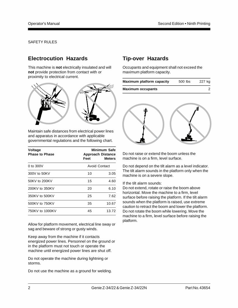
This machine is not electrically insulated and willnot provide protection from contact with orproximity to electrical current.
Maintain safe distances from electrical power linesand apparatus in accordance with applicablegovernmental regulations and the following chart.
Voltage Minimum SafePhase to Phase Approach Distance
Feet Meters
0 to 300V Avoid Contact
300V to 50KV 10 3.05
50KV to 200KV 15 4.60
200KV to 350KV 20 6.10
350KV to 500KV 25 7.62
500KV to 750KV 35 10.67
750KV to 1000KV 45 13.72
Allow for platform movement, electrical line sway orsag and beware of strong or gusty winds.
Keep away from the machine if it contactsenergized power lines. Personnel on the ground orin the platform must not touch or operate themachine until energized power lines are shut off.
Do not operate the machine during lightning orstorms.
Do not use the machine as a ground for welding.
Tip-over Hazards
Occupants and equipment shall not exceed themaximum platform capacity.
Maximum platform capacity 500 lbs 227 kg
Maximum occupants 2
Do not raise or extend the boom unless themachine is on a firm, level surface.
Do not depend on the tilt alarm as a level indicator.The tilt alarm sounds in the platform only when themachine is on a severe slope.
If the tilt alarm sounds:Do not extend, rotate or raise the boom abovehorizontal. Move the machine to a firm, levelsurface before raising the platform. If the tilt alarmsounds when the platform is raised, use extremecaution to retract the boom and lower the platform.Do not rotate the boom while lowering. Move themachine to a firm, level surface before raising theplatform.
Part No. 43654 Genie Z-34/22 & Genie Z-34/22N 3
Operator's ManualSecond Edition • Ninth Printing
SAFETY RULES
Do not drive the machine on a slope that exceedsthe maximum uphill, downhill or side slope rating ofthe machine. Slope rating applies to machines inthe stowed position.
Maximum slope rating, stowed position,
Counterweight uphill 20% (11°)
Counterweight downhill 20% (11°)
Side slope 20% (11°)
Note: Slope rating is subject to ground conditionsand adequate traction.
Do not drive the machine on or near uneven terrain,unstable surfaces or other hazardous conditionswith the boom raised or extended.
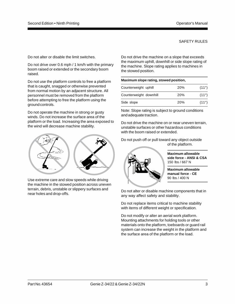
Do not push off or pull toward any object outsideof the platform.
Maximum allowableside force - ANSI & CSA150 lbs / 667 N
Maximum allowablemanual force - CE90 lbs / 400 N
Do not alter or disable machine components that inany way affect safety and stability.
Do not replace items critical to machine stabilitywith items of different weight or specification.
Do not modify or alter an aerial work platform.Mounting attachments for holding tools or othermaterials onto the platform, toeboards or guard railsystem can increase the weight in the platform andthe surface area of the platform or the load.
Do not alter or disable the limit switches.
Do not drive over 0.6 mph / 1 km/h with the primaryboom raised or extended or the secondary boomraised.
Do not use the platform controls to free a platformthat is caught, snagged or otherwise preventedfrom normal motion by an adjacent structure. Allpersonnel must be removed from the platformbefore attempting to free the platform using theground controls.
Do not operate the machine in strong or gustywinds. Do not increase the surface area of theplatform or the load. Increasing the area exposed tothe wind will decrease machine stability.
Use extreme care and slow speeds while drivingthe machine in the stowed position across uneventerrain, debris, unstable or slippery surfaces andnear holes and drop-offs.
4 Genie Z-34/22 & Genie Z-34/22N Part No. 43654
Operator's Manual Second Edition • Ninth Printing
SAFETY RULES
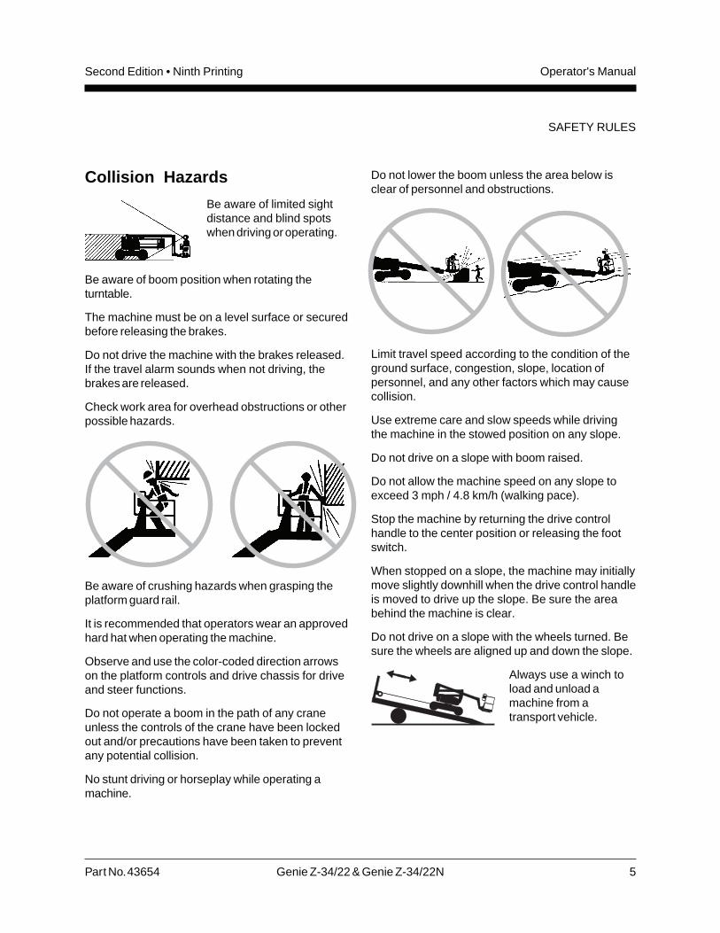
Fall Hazards
Occupants must wear asafety belt or harness andcomply with applicablegovernmental regulations.Attach lanyard to the anchorprovided in the platform.
Do not sit, stand or climb on the platform guardrails. Maintain a firm footing on the platform floor atall times.
Do not climb down from the platform when raised.
Keep the platform floor clear of debris.
Lower the platform entry mid-rail or close the entrygate before operating.
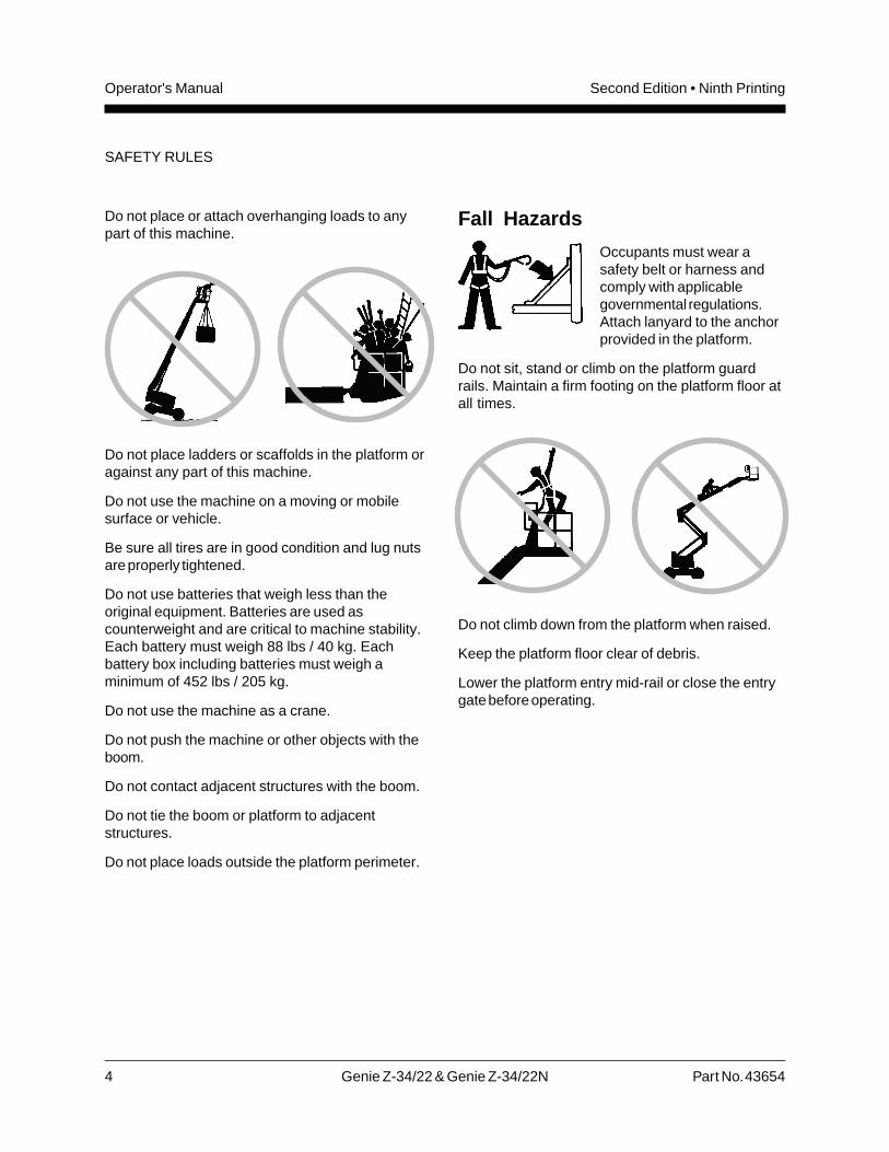
Do not place or attach overhanging loads to anypart of this machine.
Do not place ladders or scaffolds in the platform oragainst any part of this machine.
Do not use the machine on a moving or mobilesurface or vehicle.
Be sure all tires are in good condition and lug nutsare properly tightened.
Do not use batteries that weigh less than theoriginal equipment. Batteries are used ascounterweight and are critical to machine stability.Each battery must weigh 88 lbs / 40 kg. Eachbattery box including batteries must weigh aminimum of 452 lbs / 205 kg.
Do not use the machine as a crane.
Do not push the machine or other objects with theboom.
Do not contact adjacent structures with the boom.
Do not tie the boom or platform to adjacentstructures.
Do not place loads outside the platform perimeter.
Part No. 43654 Genie Z-34/22 & Genie Z-34/22N 5
Operator's ManualSecond Edition • Ninth Printing
SAFETY RULES
Collision Hazards
Be aware of limited sightdistance and blind spotswhen driving or operating.
Be aware of boom position when rotating theturntable.
The machine must be on a level surface or securedbefore releasing the brakes.
Do not drive the machine with the brakes released.If the travel alarm sounds when not driving, thebrakes are released.
Check work area for overhead obstructions or otherpossible hazards.
Be aware of crushing hazards when grasping theplatform guard rail.
It is recommended that operators wear an approvedhard hat when operating the machine.
Observe and use the color-coded direction arrowson the platform controls and drive chassis for driveand steer functions.
Do not operate a boom in the path of any craneunless the controls of the crane have been lockedout and/or precautions have been taken to preventany potential collision.
No stunt driving or horseplay while operating amachine.
Do not lower the boom unless the area below isclear of personnel and obstructions.
Limit travel speed according to the condition of theground surface, congestion, slope, location ofpersonnel, and any other factors which may causecollision.
Use extreme care and slow speeds while drivingthe machine in the stowed position on any slope.
Do not drive on a slope with boom raised.
Do not allow the machine speed on any slope toexceed 3 mph / 4.8 km/h (walking pace).
Stop the machine by returning the drive controlhandle to the center position or releasing the footswitch.
When stopped on a slope, the machine may initiallymove slightly downhill when the drive control handleis moved to drive up the slope. Be sure the areabehind the machine is clear.
Do not drive on a slope with the wheels turned. Besure the wheels are aligned up and down the slope.
Always use a winch toload and unload amachine from atransport vehicle.
6 Genie Z-34/22 & Genie Z-34/22N Part No. 43654
Operator's Manual Second Edition • Ninth Printing
Component Damage Hazard
Do not use the machine as a ground for welding.
Damaged Machine Hazards
Do not use a damaged or malfunctioning machine.
Conduct a thorough pre-operation inspection of themachine and test all functions before each workshift. Immediately tag and remove from service adamaged or malfunctioning machine.
Be sure all maintenance has been performed asspecified in this manual and theGenie Z-34/22 & Genie Z-34/22N Service Manual.
Be sure all decals are in place and legible.
Be sure the operator’s, safety and responsibilitiesmanuals are complete, legible and in the storagecontainer located on the platform.
Bodily Injury Hazard
Do not operate the machine with a hydraulic oil orair leak. An air leak or hydraulic leak can penetrateand/or burn skin.
SAFETY RULES
Decal Legend
Genie product decals use symbols, color codingand signal words to identify the following:
Safety alert symbol—used to alertpersonnel to potential personalinjury hazards. Obey all safetymessages that follow this symbolto avoid possible injury or death.
Red—used to indicate thepresence of an imminentlyhazardous situation which, if notavoided, will result in death orserious injury.
Orange—used to indicate thepresence of a potentiallyhazardous situation which, if notavoided, could result in death orserious injury.
Yellow with safety alert symbol—used to indicate the presence of apotentially hazardous situationwhich, if not avoided, may causeminor or moderate injury.
Yellow without safety alertsymbol—used to indicate thepresence of a potentiallyhazardous situation which, if notavoided, may result in propertydamage.
Green—used to indicate operationor maintenance information.
Part No. 43654 Genie Z-34/22 & Genie Z-34/22N 7
Operator's ManualSecond Edition • Ninth Printing
SAFETY RULES
Battery Safety
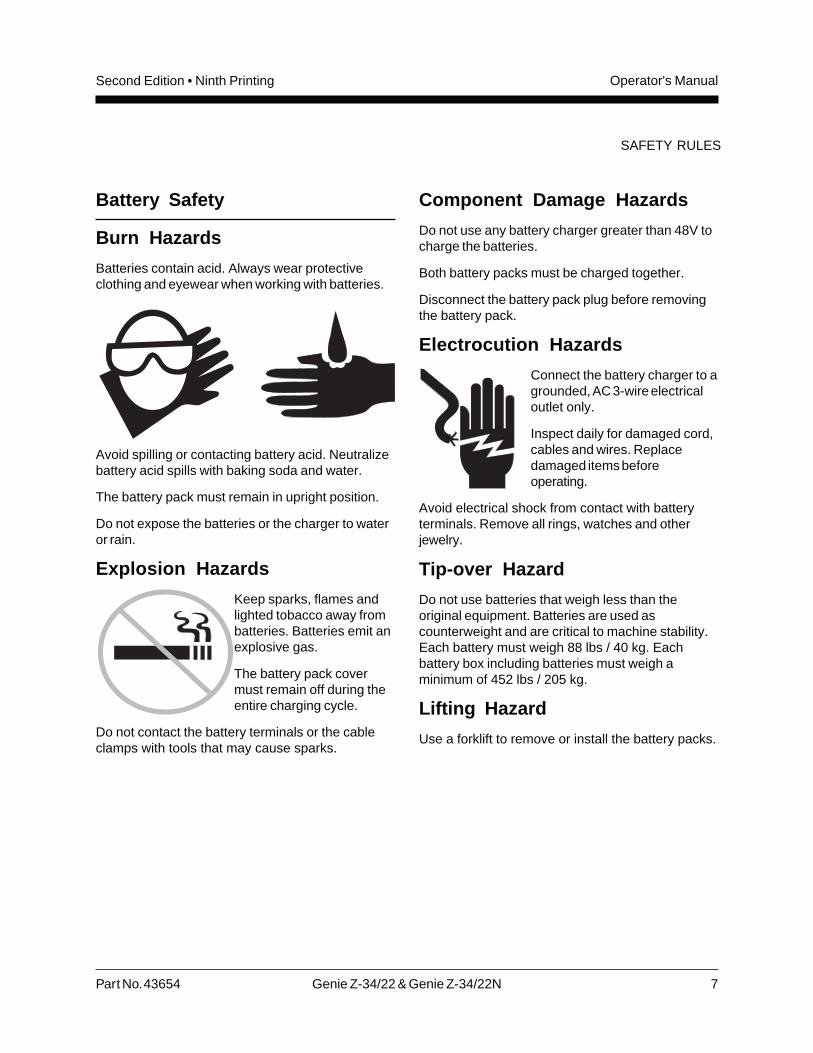
Burn Hazards
Batteries contain acid. Always wear protectiveclothing and eyewear when working with batteries.
Avoid spilling or contacting battery acid. Neutralizebattery acid spills with baking soda and water.
The battery pack must remain in upright position.
Do not expose the batteries or the charger to wateror rain.
Explosion Hazards
Keep sparks, flames andlighted tobacco away frombatteries. Batteries emit anexplosive gas.
The battery pack covermust remain off during theentire charging cycle.
Do not contact the battery terminals or the cableclamps with tools that may cause sparks.
Component Damage Hazards
Do not use any battery charger greater than 48V tocharge the batteries.
Both battery packs must be charged together.
Disconnect the battery pack plug before removingthe battery pack.
Electrocution Hazards
Connect the battery charger to agrounded, AC 3-wire electricaloutlet only.
Inspect daily for damaged cord,cables and wires. Replacedamaged items beforeoperating.
Avoid electrical shock from contact with batteryterminals. Remove all rings, watches and otherjewelry.
Tip-over Hazard
Do not use batteries that weigh less than theoriginal equipment. Batteries are used ascounterweight and are critical to machine stability.Each battery must weigh 88 lbs / 40 kg. Eachbattery box including batteries must weigh aminimum of 452 lbs / 205 kg.
Lifting Hazard
Use a forklift to remove or install the battery packs.
8 Genie Z-34/22 & Genie Z-34/22N Part No. 43654
Operator's Manual Second Edition • Ninth Printing
Controls
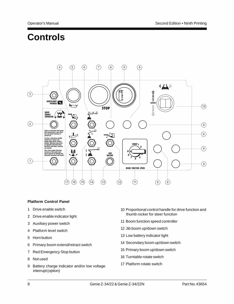
Platform Control Panel
1 Drive enable switch
2 Drive enable indicator light
3 Auxiliary power switch
4 Platform level switch
5 Horn button
6 Primary boom extend/retract switch
7 Red Emergency Stop button
8 Not used
9 Battery charge indicator and/or low voltageinterrupt (option)
10 Proportional control handle for drive function andthumb rocker for steer function
11 Boom function speed controller
12 Jib boom up/down switch
13 Low battery indicator light
14 Secondary boom up/down switch
15 Primary boom up/down switch
16 Turntable rotate switch
17 Platform rotate switch
Part No. 43654 Genie Z-34/22 & Genie Z-34/22N 9
Operator's ManualSecond Edition • Ninth Printing
CONTROLS
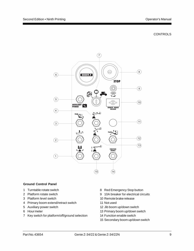
Ground Control Panel
1 Turntable rotate switch2 Platform rotate switch3 Platform level switch4 Primary boom extend/retract switch5 Auxiliary power switch6 Hour meter7 Key switch for platform/off/ground selection
8 Red Emergency Stop button9 10A breaker for electrical circuits10 Remote brake release11 Not used12 Jib boom up/down switch13 Primary boom up/down switch14 Function enable switch15 Secondary boom up/down switch
10 Genie Z-34/22 & Genie Z-34/22N Part No. 43654
Operator's Manual Second Edition • Ninth Printing
Pre-operation Inspection
Do Not Operate Unless:
You learn and practice the principles of safemachine operation contained in this operator'smanual.
1 Avoid hazardous situations.
2 Always perform a pre-operationinspection.
Know and understand the pre-operationinspection before going on to the nextsection.
3 Always perform function tests prior to use.
4 Inspect the workplace.
5 Only use the machine as it was intended.
Fundamentals
It is the responsibility of the operator to perform apre-operation inspection and routine maintenance.
The pre-operation inspection is a visual inspectionperformed by the operator prior to each work shift.The inspection is designed to discover if anythingis apparently wrong with a machine before theoperator performs the function tests.
The pre-operation inspection also serves todetermine if routine maintenance procedures arerequired. Only routine maintenance itemsspecified in this manual may be performed by theoperator.
Refer to the list on the next page and check eachof the items and locations for modifications,damage or loose or missing parts.
A damaged or modified machine must never beused. If damage or any variation from factorydelivered condition is discovered, the machinemust be tagged and removed from service.
Repairs to the machine may only be made by aqualified service technician, according to themanufacturer's specifications. After repairs arecompleted, the operator must perform apre-operation inspection again before going on tothe function tests.
Scheduled maintenance inspections shall beperformed by qualified service technicians,according to the manufacturer's specifications andthe requirements listed in the responsibilitiesmanual.
Part No. 43654 Genie Z-34/22 & Genie Z-34/22N 11
Operator's ManualSecond Edition • Ninth Printing
Pre-operation Inspection
! Be sure that the operator's, safety andresponsibilities manuals are complete, legibleand in the storage container located on theplatform.
! Be sure that all decals are legible and in place.See Decals section.
! Check for hydraulic oil leaks and proper oil level.Add oil if needed. See Maintenance section.
! Check for battery fluid leaks and proper fluidlevel. Add distilled water if needed. SeeMaintenance section.
Check the following components or areas fordamage, modifications and improperly installed ormissing parts:
! Electrical components, wiring and electricalcables
! Hydraulic power unit, tank, hoses,fittings, cylinders and manifolds
! Drive and turntable motors and drive hubs
! Boom wear pads
! Tires and wheels
! Limit switches, alarms and horn
! Nuts, bolts and other fasteners
! Platform entry mid-rail bar or gate
PRE-OPERATION INSPECTION
Check entire machine for:
! Crack in welds or structural components
! Dents or damage to machine
! Be sure that all structural and other criticalcomponents are present and all associatedfasteners and pins are in place and properlytightened.
! Be sure that both battery packs are in place,latched and properly connected.
! After you complete your inspection, be sure thatall compartment covers are in place andlatched.
12 Genie Z-34/22 & Genie Z-34/22N Part No. 43654
Operator's Manual Second Edition • Ninth Printing
Maintenance
Observe and Obey:
Only routine maintenance items specified inthis manual shall be performed by the operator.
Scheduled maintenance inspections shall becompleted by qualified service technicians,according to the manufacturer's specificationsand the requirements specified in theresponsibilities manual.
Maintenance Symbols Legend
The following symbols have beenused in this manual to helpcommunicate the intent of theinstructions. When one or more ofthe symbols appear at thebeginning of a maintenanceprocedure, it conveys the meaningbelow.
Indicates that tools will be requiredto perform this procedure.
Indicates that new parts will berequired to perform this procedure.
Check the Hydraulic Oil Level
Maintaining the hydraulic oil at the proper level isessential to machine operation. Improper hydraulicoil levels can damage hydraulic components. Dailychecks allow the inspector to identify changes inoil level that might indicate the presence ofhydraulic system problems.
1 Be sure that the boom is in the stowed position.
2 Check the hydraulic oil level.
Result: The hydraulic oil level should be at theFULL mark on the dipstick or visible in the sightglass or between the FULL and ADD marks on thehydraulic tank.
3 Add hydraulic oil if necessary.
Hydraulic Oil Specifications
Hydraulic oil type Refer to machine decal
Part No. 43654 Genie Z-34/22 & Genie Z-34/22N 13
Operator's ManualSecond Edition • Ninth Printing
Check the Batteries
Proper battery condition is essential to goodengine performance and operational safety.Improper fluid levels or damaged cables andconnections can result in engine componentdamage and hazardous conditions.
Electrocution hazard. Contact withhot or live circuits could result indeath or serious injury. Removeall rings, watches and otherjewelry.
Bodily injury hazard. Batteriescontain acid. Avoid spilling orcontacting battery acid. Neutralizebattery acid spills with bakingsoda and water.
Perform this test after fullycharging the batteries.
1 Put on protective clothing and eye wear.
2 Be sure that the battery cable connections aretight and free of corrosion.
3 Remove the battery vent caps.
4 Check the battery acid level. If necessary,replenish with distilled water to the bottom of thebattery fill tube. Do not overfill.
5 Install the vent caps.
MAINTENANCE
Scheduled Maintenance
Maintenance performed quarterly, annually andevery two years must be completed by a persontrained and qualified to perform maintenance on thismachine according to the procedures found in theservice manual for this machine.
Machines that have been out of service for morethan three months must receive the quarterlyinspection before they are put back into service.
14 Genie Z-34/22 & Genie Z-34/22N Part No. 43654
Operator's Manual Second Edition • Ninth Printing
Function Tests
Do Not Operate Unless:
You learn and practice the principles of safemachine operation contained in this operator'smanual.
1 Avoid hazardous situations.
2 Always perform a pre-operationinspection.
3 Always perform function tests prior touse.
Know and understand the function testsbefore going on to the next section.
4 Inspect the workplace.
5 Only use the machine as it was intended.
1 Select a test area that is firm, level and free ofobstruction.
At the Ground Controls
2 Turn the key switch to ground control.
3 Pull out the red Emergency Stop button tothe on position.
Result: The beacon (if equipped) should flash.
Test Emergency Stop
4 Push in the red Emergency Stop button to theoff position.
Result: All ground and platform control functionsshould not operate.
5 Pull out the red Emergency Stop button tothe on position.
Fundamentals
The function tests are designed to discover anymalfunctions before the machine is put intoservice. The operator must follow the step-by-stepinstructions to test all machine functions.
A malfunctioning machine must never be used. Ifmalfunctions are discovered, the machine must betagged and removed from service. Repairs to themachine may only be made by a qualified servicetechnician, according to the manufacturer’sspecifications.
After repairs are completed, the operator mustpreform a pre-operation inspection and functiontests again before putting the machine intoservice.
Part No. 43654 Genie Z-34/22 & Genie Z-34/22N 15
Operator's ManualSecond Edition • Ninth Printing
FUNCTION TESTS
Test Auxiliary Controls
11 Turn the key switch to ground control.
12 Simultaneously hold the auxiliary power switchon and activate each boom function toggleswitch.
Note: To conserve battery power, test eachfunction through a partial cycle.
Result: All boom functions should operate.
13 Turn the key switch to platform control.
At the Platform Controls
Test Emergency Stop
14 Push in the platform red Emergency Stop buttonto the off position.
Result: All platform control functions should notoperate.
Test the Horn
15 Pull out the red Emergency Stop button to theon position.
16 Push the horn button.
Result: The horn should sound.
Test the Foot Switch
17 Do not press down the foot switch. Activateeach machine function.
Result: The machine functions should notoperate.
Test the Boom Functions
6 Do not hold the function enable switch to eitherside. Attempt to activate each boom andplatform function toggle switch.
Result: All boom and platform functions shouldnot operate.
7 Hold the function enable switch to either sideand activate each boom and platform functiontoggle switch.
Result: All boom and platform functions shouldoperate through a full cycle. The descent alarm(if equipped) should sound while the boom islowering.
Machines equipped with Platform Level ControlDisable Function: The platform level toggle switchwill not operate when the primary boom is raisedpast the drive speed limit switch.
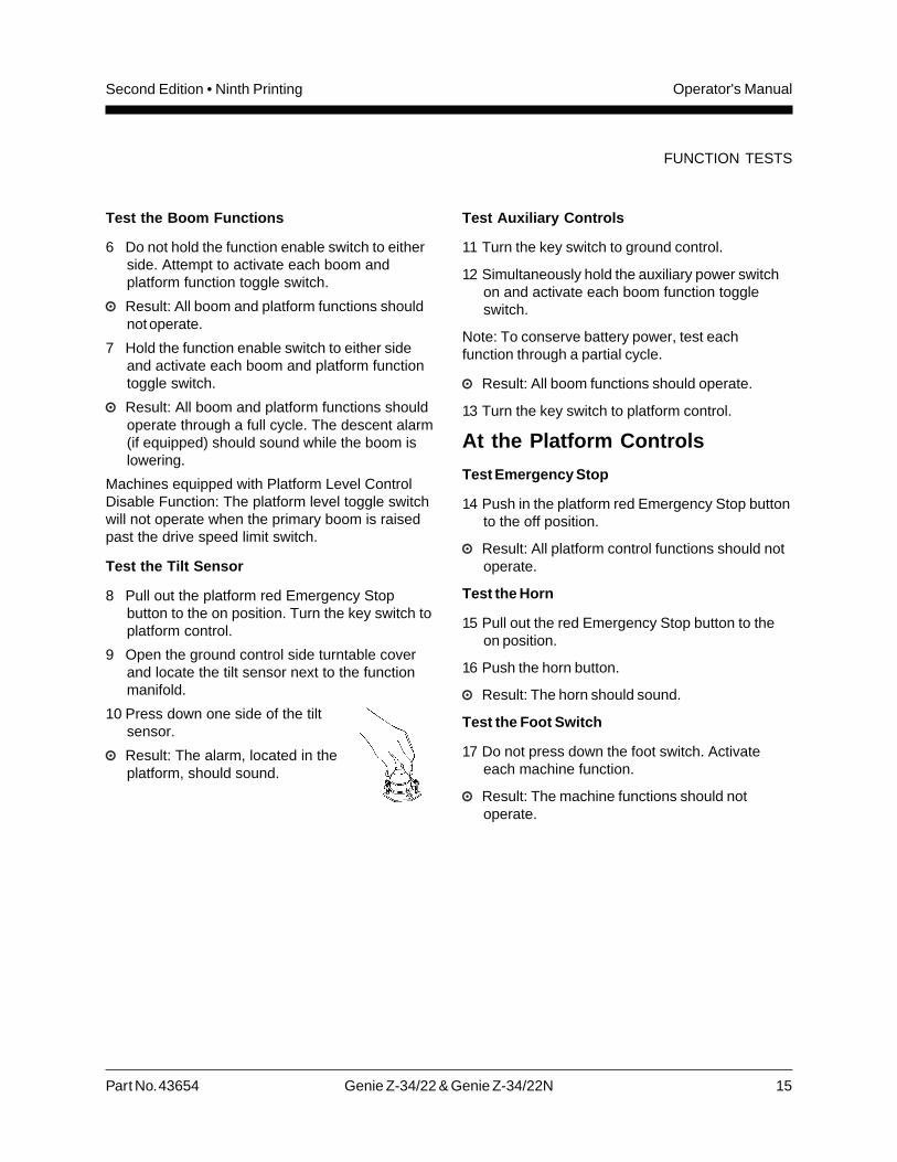
Test the Tilt Sensor
8 Pull out the platform red Emergency Stopbutton to the on position. Turn the key switch toplatform control.
9 Open the ground control side turntable coverand locate the tilt sensor next to the functionmanifold.
10 Press down one side of the tiltsensor.
Result: The alarm, located in theplatform, should sound.
16 Genie Z-34/22 & Genie Z-34/22N Part No. 43654
Operator's Manual Second Edition • Ninth Printing
FUNCTION TESTS
Test Machine Functions
18 Move the lift/drive select switch to the liftposition (if equipped).
19 Press down the foot switch.
20 Activate each machine function toggle switch.
Result: All boom/platform functions shouldoperate through a full cycle.
Note: Control the speed of boom functions byadjusting the boom function speed controller.Drive and steer functions are not affected by theboom function speed controller.
Machines equipped with Platform Level ControlDisable Function: The platform level toggle switchwill not operate when the primary boom is raisedpast the drive speed limit switch.
Test the Steering
21 Move the lift/drive select switch to the driveposition (if equipped).
22 Press down the foot switch.
23 Depress the thumb rocker switch on top of thedrive control handle in the direction identifiedby the blue triangle on the control panel.
Result: The steer wheels should turn in thedirection that the blue triangles point on thedrive chassis.
24 Depress the thumb rocker switch in the directionidentified by the yellow triangle on the controlpanel.
Result: The steer wheels should turn in thedirection that the yellow triangles point on thedrive chassis.
Test Drive and Braking
25 Move the lift/drive select switch to the driveposition (if equipped).
26 Press down the foot switch.
27 Slowly move the drive control handle in thedirection indicated by the blue arrow on thecontrol panel until the machine begins to move,then return the handle to the center position.
Result: The travel alarm should sound. Themachine should move in the direction that theblue arrow points on the drive chassis, thencome to an abrupt stop.
28 Slowly move the drive control handle in thedirection indicated by the yellow arrow on thecontrol panel until the machine begins to move,then return the handle to the center position.
Result: The travel alarm should sound. Themachine should move in the direction that theyellow arrow points on the drive chassis, thencome to an abrupt stop.
Note: The brakes must be able to hold the machineon any slope it is able to climb.
Part No. 43654 Genie Z-34/22 & Genie Z-34/22N 17
Operator's ManualSecond Edition • Ninth Printing
Test Limited Drive Speed
29 Move the lift/drive select switch to the liftposition (if equipped).
30 Press down the foot switch.
31 Raise the primary boom 1 foot / 30 cm.
32 Move the lift/drive select switch to the driveposition (if equipped).
33 Slowly move the drive control handle to the fulldrive position.
Result: The maximum achievable drive speedwith the primary boom raised should notexceed 1 foot / 30 cm per second.
34 Move the lift/drive select switch to the liftposition (if equipped).
35 Lower the boom to the stowed position.
36 Raise the secondary boom 1 foot / 30 cm.
37 Move the lift/drive select switch to the driveposition (if equipped).
38 Slowly move the drive control handle to the fulldrive position.
Result: The maximum achievable drive speedwith the secondary boom raised should notexceed 1 foot / 30 cm per second.
39 Move the lift/drive select switch to the liftposition (if equipped).
40 Lower the boom to the stowed position.
41 Extend the primary boom 1 foot / 30 cm.
42 Move the lift/drive select switch to the driveposition (if equipped).
43 Slowly move the drive control handle to the fulldrive position.
Result: The maximum achievable drive speedwith the primary boom extended should notexceed 1 foot / 30 cm per second.
If the drive speed with the primary boom raised orextended or the secondary boom raised exceeds1 foot / 30 cm per second, immediately tag andremove the machine from service.
Test the Drive Enable System
44 Move the lift/drive select switch to the liftposition (if equipped).
45 Press down the foot switch and retract theprimary boom to the stowed position.
46 Rotate the turntable until the boom moves pastone of the non-steer wheels.
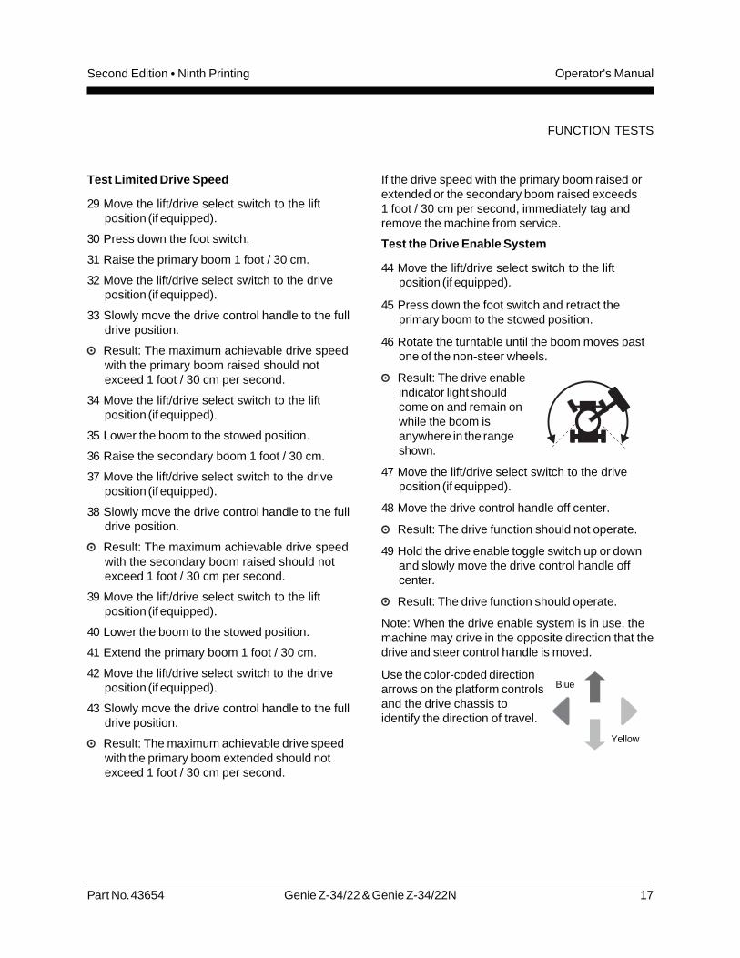
Result: The drive enableindicator light shouldcome on and remain onwhile the boom isanywhere in the rangeshown.
47 Move the lift/drive select switch to the driveposition (if equipped).
48 Move the drive control handle off center.
Result: The drive function should not operate.
49 Hold the drive enable toggle switch up or downand slowly move the drive control handle offcenter.
Result: The drive function should operate.
Note: When the drive enable system is in use, themachine may drive in the opposite direction that thedrive and steer control handle is moved.
Use the color-coded directionarrows on the platform controlsand the drive chassis toidentify the direction of travel.
FUNCTION TESTS
Blue
Yellow
18 Genie Z-34/22 & Genie Z-34/22N Part No. 43654
Operator's Manual Second Edition • Ninth Printing
Test the Lift/Drive Select Function(CE models)
Machines with lift/drive select switch:
50 Move the lift/drive select switch to the liftposition.
51 Press down the foot switch.
52 Move the drive control handle off center.
Result: No drive functions should operate.
53 Activate each boom function toggle switch.
Result: All boom functions should operate.
54 Move the lift/drive select switch to the driveposition.
55 Press down the foot switch.
56 Activate each boom function toggle switch.
Result: No boom functions should operate.
57 Move the drive control handle off center.
Result: The drive functions should operate.
Machines without lift/drive select switch:
58 Press down the foot switch.
59 Move the drive control handle off center andactivate a boom function toggle switch.
Result: No boom functions should operate. Themachine will move in the direction indicated onthe control panel.
FUNCTION TESTS
Test Auxiliary Controls
60 Move the lift/drive select switch to theappropriate position (if equipped).
61 Press down the foot switch.
62 Simultaneously hold the auxiliary power switchon and activate each function control handle ortoggle switch.
Note: To conserve battery power, test eachfunction through a partial cycle.
Result: All boom, steer and drive functionsshould operate.
Part No. 43654 Genie Z-34/22 & Genie Z-34/22N 19
Operator's ManualSecond Edition • Ninth Printing
Workplace Inspection
Workplace Inspection
Be aware of and avoid the following hazardoussituations:
· drop-offs or holes
· bumps, floor obstructions or debris
· overhead obstructions and high voltageconductors
· hazardous locations
· inadequate surface support to withstand allload forces imposed by the machine
· wind and weather conditions
· the presence of unauthorized personnel
· other possible unsafe conditions
· Determine the slope of any surface in the pathof travel on the job site
Do Not Operate Unless:
You learn and practice the principles of safemachine operation contained in this operator'smanual.
1 Avoid hazardous situations.
2 Always perform a pre-operationinspection.
3 Always perform function tests prior to use.
4 Inspect the workplace.
Know and understand the workplaceinspection before going on to the nextsection.
5 Only use the machine as it was intended.
Fundamentals
The workplace inspection helps the operatordetermine if the workplace is suitable for safemachine operation. It should be performed by theoperator prior to moving the machine to theworkplace.
It is the operator's responsibility to read andremember the workplace hazards, then watch forand avoid them while moving, setting up andoperating the machine.
20 Genie Z-34/22 & Genie Z-34/22N Part No. 43654
Operator's Manual Second Edition • Ninth Printing
Operating Instructions
Do Not Operate Unless:
You learn and practice the principles of safemachine operation contained in this operator'smanual.
1 Avoid hazardous situations.
2 Always perform a pre-operationinspection.
3 Always perform function tests prior to use.
4 Inspect the workplace.
5 Only use the machine as it was intended.
Fundamentals
The Operating Instructions section providesinstructions for each aspect of machine operation.It is the operator's responsibility to follow all thesafety rules and instructions in the operator's,safety and responsibilities manuals.
Using the machine for anything other than liftingpersonnel and tools to an aerial work site is unsafeand dangerous.
Only trained and authorized personnel should bepermitted to operate a machine. If more than oneoperator is expected to use a machine at differenttimes in the same work shift, they must all bequalified operators and are all expected to follow allsafety rules and instructions in the operator's,safety and responsibilities manuals. That meansevery new operator should perform a pre-operationinspection, function tests, and a workplaceinspection before using the machine.
Part No. 43654 Genie Z-34/22 & Genie Z-34/22N 21
Operator's ManualSecond Edition • Ninth Printing
OPERATING INSTRUCTIONS
Emergency Stop
Push in the red Emergency Stop button to the offposition at the ground or platform controls to stopall machine functions.
Repair any function that operates when the redEmergency Stop button is pushed in.
Selecting and operating the ground controls willoverride the platform Red Emergency Stop button.
Auxiliary Controls
Use auxiliary power if the primary power sourcefails.
1 Turn the key switch to ground or platformcontrol.
2 Pull out the red Emergency Stop button to theon position.
3 Move the lift/drive select switch to theappropriate position (if equipped) whenoperating the auxiliary controls from theplatform.
4 Press down the foot switch when operating theauxiliary controls from the platform.
5 Simultaneously hold the auxiliary power switchon and activate the desired function.
The boom, steer and drive functions will operatewith auxiliary power.
Operation from Ground
1 Turn the key switch to ground control.
2 Pull out the red Emergency Stop button tothe on position.
3 Be sure both battery packs are connectedbefore operating the machine.
To Position Platform
1 Hold the function enable switch to either side.
2 Move the appropriate toggle switch accordingto the markings on the control panel.
Drive and steer functions are not available from theground controls.
Machines equipped with Platform Level ControlDisable Function: The platform level toggle switchwill not operate when the boom is raised past thedrive speed limit switch.
22 Genie Z-34/22 & Genie Z-34/22N Part No. 43654
Operator's Manual Second Edition • Ninth Printing
Operation from Platform
1 Turn the key switch to platform control.
2 Pull out both ground and platform redEmergency Stop buttons to the on position.
3 Be sure that both battery packs are connectedbefore operating the machine.
To Position Platform
1 Set the boom function speed controller to thedesired speed.
Note: Drive and steer functions are not affected bythe boom function speed controller.
2 Move the lift/drive select switch to the liftposition (if equipped).
3 Press down the foot switch.
4 Move the appropriate toggle switch according tothe markings on the control panel.
Machines equipped with Platform Level ControlDisable Function: The platform level toggle switchwill not operate when the boom is raised past thedrive speed limit switch.
To Steer
1 Move the lift/drive select switch to the driveposition (if equipped).
2 Press down the foot switch.
3 Turn the steer wheels with the thumb rockerswitch located on top of the drive controlhandle.
Use the color-coded direction arrows on theplatform controls and the drive chassis to identifythe direction the wheels will turn.
To Drive
1 Move the lift/drive select switch to the driveposition (if equipped).
2 Press down the foot switch.
3 Increase speed: Slowly move the drive controlhandle off center.
Decrease speed: Slowly move the drive controlhandle toward center.
Stop: Return the drive control handle to center orrelease the foot switch.
Use the color-coded direction arrows on theplatform controls and the drive chassis to identifythe direction the machine will travel.
The travel alarm will sound when the drive controlleris moved off center.
Note: When the turntable is rotated so the boom ispast the non-steer tires, the machine may move inthe opposite direction that the drive and steercontrols are moved.
Machine travel speed is restricted when the boomsare raised or extended.
Battery condition will affect the ability of themachine to climb a slope.
OPERATING INSTRUCTIONS
Part No. 43654 Genie Z-34/22 & Genie Z-34/22N 23
Operator's ManualSecond Edition • Ninth Printing
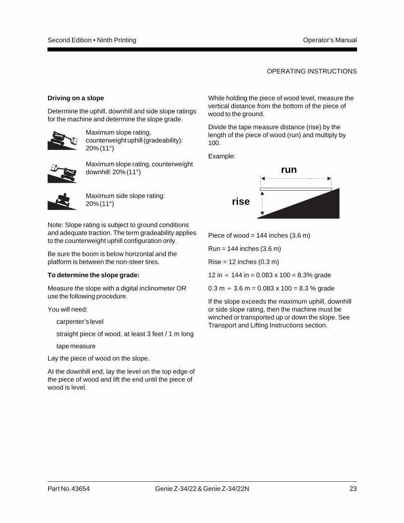
Driving on a slope
Determine the uphill, downhill and side slope ratingsfor the machine and determine the slope grade.
Maximum slope rating,counterweight uphill (gradeability):20% (11°)
Maximum slope rating, counterweightdownhill: 20% (11°)
Maximum side slope rating:20% (11°)
Note: Slope rating is subject to ground conditionsand adequate traction. The term gradeability appliesto the counterweight uphill configuration only.
Be sure the boom is below horizontal and theplatform is between the non-steer tires.
To determine the slope grade:
Measure the slope with a digital inclinometer ORuse the following procedure.
You will need:
carpenter’s level
straight piece of wood, at least 3 feet / 1 m long
tape measure
Lay the piece of wood on the slope.
At the downhill end, lay the level on the top edge ofthe piece of wood and lift the end until the piece ofwood is level.
While holding the piece of wood level, measure thevertical distance from the bottom of the piece ofwood to the ground.
Divide the tape measure distance (rise) by thelength of the piece of wood (run) and multiply by100.
Example:
Piece of wood = 144 inches (3.6 m)
Run = 144 inches (3.6 m)
Rise = 12 inches (0.3 m)
12 in ÷ 144 in = 0.083 x 100 = 8.3% grade
0.3 m ÷ 3.6 m = 0.083 x 100 = 8.3 % grade
If the slope exceeds the maximum uphill, downhillor side slope rating, then the machine must bewinched or transported up or down the slope. SeeTransport and Lifting Instructions section.
run
rise
OPERATING INSTRUCTIONS
24 Genie Z-34/22 & Genie Z-34/22N Part No. 43654
Operator's Manual Second Edition • Ninth Printing
OPERATING INSTRUCTIONS
Driving Up/Down Slopes
Drive/Brake Control Theory
Brakes release progressively as the drive controlhandle is moved out of neutral in either direction.Brakes apply progressively as the drive controlhandle is moved toward the neutral position. If themachine is on a slope, the progressive release/application of the brakes combined with torque fromthe drive motors allows you to control the speed ofthe machine. For this reason, in somecircumstances it is more effective to drive down asloped surface by moving the drive control handlein the uphill direction. This is called “plug braking.”Apply these principles for driving on a slope byfollowing the instructions below.
Driving up a slope
Be sure the platform is fully lowered and theplatform is between the drive wheels. Be sure thewheels are aligned up and down the slope.
1 Press down the foot switch.
2 Move the drive control handle firmly.
When stopped on a slope, the machine may initiallymove slightly downhill when the drive control handleis moved to drive up the slope. Be sure the areabehind the machine is clear.
Driving down a slope
Be sure the platform is fully lowered and theplatform is between the drive wheels. Be sure thewheels are aligned up and down the slope.
1 Position the steer wheels on the downhill side ofslope.
2 Press down the foot switch.
3 On steeper slopes, it may be more effective tomove the drive control handle in the uphilldirection (plug braking) in order to drive downhill.For this reason, no matter what slope you areon, always begin the process of driving downhillby slowly moving the drive control handle in theuphill direction. Use small movements of thedrive control handle to control the machinespeed.
If the machine moves uphill instead of downhill, theslope is too small to use plug braking. Move thedrive control handle back to the neutral position toapply the brakes and proceed as follows:
4 Slowly move the drive control handle downhill.Use small movements of the drive controlhandle to control the machine speed.
To stop the machine completely, return the drivecontrol handle to the center (neutral position). Themachine can also be stopped by removing your footfrom the foot switch or pushing in the redEmergency Stop button.
If machine speed exceeds 3 mph / 4.8 km/h(walking pace), immediately stop the machine.
Part No. 43654 Genie Z-34/22 & Genie Z-34/22N 25
Operator's ManualSecond Edition • Ninth Printing
Drive Enable
Light on indicates that the boom has moved pasteither non-steer wheel and the drive function hasbeen interrupted.
To drive, hold the drive enable switch up or downand slowly move the drive control handle offcenter.
Be aware that the machine may move in theopposite direction that the drive and steer controlsare moved.
Always use the color-coded direction arrows onthe platform controls and the drive chassis toidentify the direction the machine will travel.
Low Battery Indicator Light
Flashing light indicates battery power is low andthe batteries need to be charged. There isadequate power left to lower the boom and movethe machine to a location where the batteries canbe charged.
Light on indicates the batteries are fully discharged.Stop using the boom and charge the batteriesimmediately.
Note: Machines equipped with Low VoltageInterrupt Option will lose primary and secondaryboom lift functions when batteries are fullydischarged.
After Each Use
1 Select a safe parking location—firm levelsurface, clear of obstruction and traffic.
2 Lower the boom to the stowed position.
3 Rotate the turntable so that the boom isbetween the non-steer wheels.
4 Turn the key switch to the off position andremove the key to secure from unauthorizeduse.
5 Chock the wheels.
6 Charge the batteries.
OPERATING INSTRUCTIONS
26 Genie Z-34/22 & Genie Z-34/22N Part No. 43654
Operator's Manual Second Edition • Ninth Printing
Battery and Charger Instructions
Observe and Obey:
Do not use an external charger or boosterbattery.
Charge the battery in a well-ventilated area.
Use proper AC input voltage for charging asindicated on the charger.
Use only a Genie authorized battery andcharger.
To Charge Battery
1 Be sure the batteries are connected beforecharging the batteries.
2 Open the battery compartment. Thecompartment should remain open for the entirecharging cycle.
3 Remove the battery vent caps and check thebattery acid level. If necessary, add onlyenough distilled water to cover the plates. Donot overfill prior to the charge cycle.
4 Replace the battery vent caps.
5 Connect the battery charger to a grounded ACcircuit.
6 Turn the battery charger on.
7 The charger will indicate when the battery is fullycharged.
8 Check the battery acid level when the chargingcycle is complete. Replenish with distilled waterto the bottom of the fill tube. Do not overfill.
Dry Battery Filling andCharging Instructions
1 Remove the battery vent caps and permanentlyremove the plastic seal from the battery ventopenings.
2 Fill each cell with battery acid (electrolyte) untilthe level is sufficient to cover the plates.
Do not fill to the maximum level until the batterycharge cycle is complete. Overfilling can cause thebattery acid to overflow during charging. Neutralizebattery acid spills with baking soda and water.
3 Install the battery vent caps.
4 Charge the battery.
5 Check the battery acid level when the chargingcycle is complete. Replenish with distilled waterto the bottom of the fill tube. Do not overfill.
OPERATING INSTRUCTIONS
Part No. 43654 Genie Z-34/22 & Genie Z-34/22N 27
Operator's ManualSecond Edition • Ninth Printing
Transport & Lifting Instructions
Observe and Obey:
The transport vehicle must be parked on a levelsurface.
The transport vehicle must be secured toprevent rolling while the machine is beingloaded.
Be sure the vehicle capacity, loading surfacesand chains or straps are sufficient to withstandthe machine weight. See serial plate.
The machine must be on a level surface orsecured before releasing the brakes.
Always use a winchto load and unload amachine from atransport vehicle.
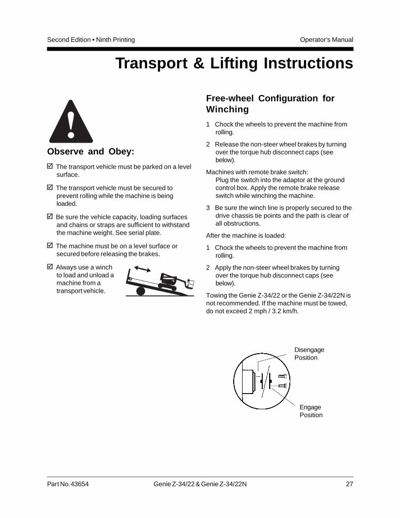
Free-wheel Configuration forWinching
1 Chock the wheels to prevent the machine fromrolling.
2 Release the non-steer wheel brakes by turningover the torque hub disconnect caps (seebelow).
Machines with remote brake switch:Plug the switch into the adaptor at the groundcontrol box. Apply the remote brake releaseswitch while winching the machine.
3 Be sure the winch line is properly secured to thedrive chassis tie points and the path is clear ofall obstructions.
After the machine is loaded:
1 Chock the wheels to prevent the machine fromrolling.
2 Apply the non-steer wheel brakes by turningover the torque hub disconnect caps (seebelow).
Towing the Genie Z-34/22 or the Genie Z-34/22N isnot recommended. If the machine must be towed,do not exceed 2 mph / 3.2 km/h.
DisengagePosition
EngagePosition
28 Genie Z-34/22 & Genie Z-34/22N Part No. 43654
Operator's Manual Second Edition • Ninth Printing
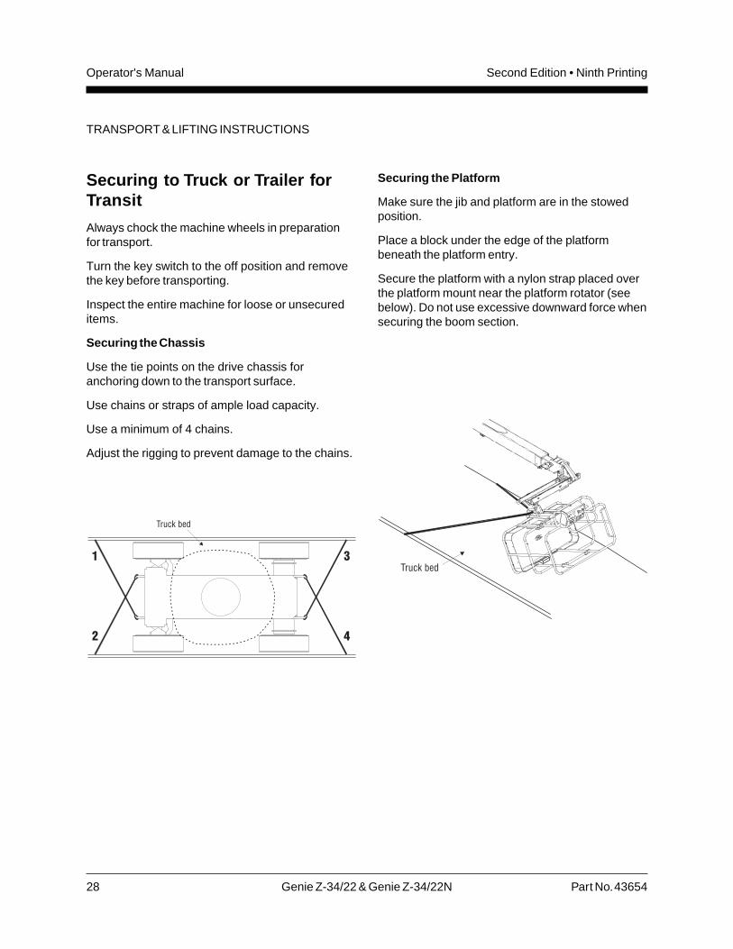
Securing to Truck or Trailer forTransit
Always chock the machine wheels in preparationfor transport.
Turn the key switch to the off position and removethe key before transporting.
Inspect the entire machine for loose or unsecureditems.
Securing the Chassis
Use the tie points on the drive chassis foranchoring down to the transport surface.
Use chains or straps of ample load capacity.
Use a minimum of 4 chains.
Adjust the rigging to prevent damage to the chains.
Securing the Platform
Make sure the jib and platform are in the stowedposition.
Place a block under the edge of the platformbeneath the platform entry.
Secure the platform with a nylon strap placed overthe platform mount near the platform rotator (seebelow). Do not use excessive downward force whensecuring the boom section.
TRANSPORT & LIFTING INSTRUCTIONS
Part No. 43654 Genie Z-34/22 & Genie Z-34/22N 29
Operator's ManualSecond Edition • Ninth Printing
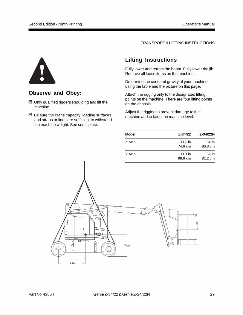
Observe and Obey:
Only qualified riggers should rig and lift themachine.
Be sure the crane capacity, loading surfacesand straps or lines are sufficient to withstandthe machine weight. See serial plate.
Lifting Instructions
Fully lower and retract the boom. Fully lower the jib.Remove all loose items on the machine.
Determine the center of gravity of your machineusing the table and the picture on this page.
Attach the rigging only to the designated liftingpoints on the machine. There are four lifting pointson the chassis.
Adjust the rigging to prevent damage to themachine and to keep the machine level.
Model Z-34/22 Z-34/22N
X Axis 30.7 in 34 in74.6 cm 86.3 cm
Y Axis 38.8 in 32 in98.6 cm 81.2 cm
TRANSPORT & LIFTING INSTRUCTIONS
30 Genie Z-34/22 & Genie Z-34/22N Part No. 43654
Operator's Manual Second Edition • Ninth Printing
Decals
Part No. Decal Description Quantity
27564 Danger - Electrocution Hazard 2
28157 Label - Dexron 1
28161 Warning - Crushing Hazard 3
28164 Notice - Hazardous Materials 1
28165 Notice - Foot Switch 1
28171 Label - No Smoking 2
28174 Power to Platform, 230V 2
28175 Caution - Compartment Access 1
28176 Notice - Missing Manuals 1
28177 Warning - Platform Rotate 2
28181 Warning - No Step or Ride 1
28235 Power to Platform, 115V 2
28236 Warning - Failure To Read . . . 1
28372 Caution - Component Damage 2
31060 Danger - Tip-over Hazard, Interlock 4
31508 Notice - Power to Charger 1
31784 Notice - Tire Specificatiions, Z-34/22 4
31785 Notice - Battery Charger Instructions 2
31788 Danger - Battery/Charger Safety 2
32700 Danger - Safety Rules 1
33952 Danger - Tilt-Alarm 1
35542 Notice - Tire Specifications, Z-34/22N 4
35583 Platform Control Panel 1
37051 Notice - Max Side Force, 150 lbs / 667 N 1
37052 Notice - Maximum Load, 500 lbs / 227 kg 1
37053 Arrow - Blue 1
37054 Arrow - Yellow 1
Part No. Decal Description Quantity
37055 Triangle - Blue 2
37056 Triangle - Yellow 2
38110 Label - Travel Alarm 1
38111 Warning - Brakes Release 1
38112 Caution - Collision Hazard 1
40299 Notice - Battery Connection Diagram 2
40300 Danger - Tip-over, Batteries 2
40434 Label - Lanyard Anchorage 2
43036 Platform Control Panel 1
43652 Ground Control Panel 1
43653 Notice - Operating Instructions, Ground 1
43658 Power to Charger, 230V 1
43663 Notice - Function Enable 1
44980 Power to Charger, 115V 1
44981 Airline to Platform 2
44986 Notice - Max Manual Force, 90 lbs / 400 N 1
52968 Cosmetic - Genie Boom 1
62930 Cosmetic - Genie Z-34/22 1
62931 Cosmetic - Genie Z-34/22 DC Power 2
62932 Cosmetic - Genie Z-34/22N 1
62933 Cosmetic - Genie Z-34/22N 2
65171 Label - Circuit Breaker & Status Light 1
72080 Ground Control Panel 1
72081 Platform Control Panel 1
72833 Label - Open 2
82366 Label - Chevron Rykon 1
114330 Danger - Safety Rules 1
114333 Notice - Operating Instructions, Platform 1
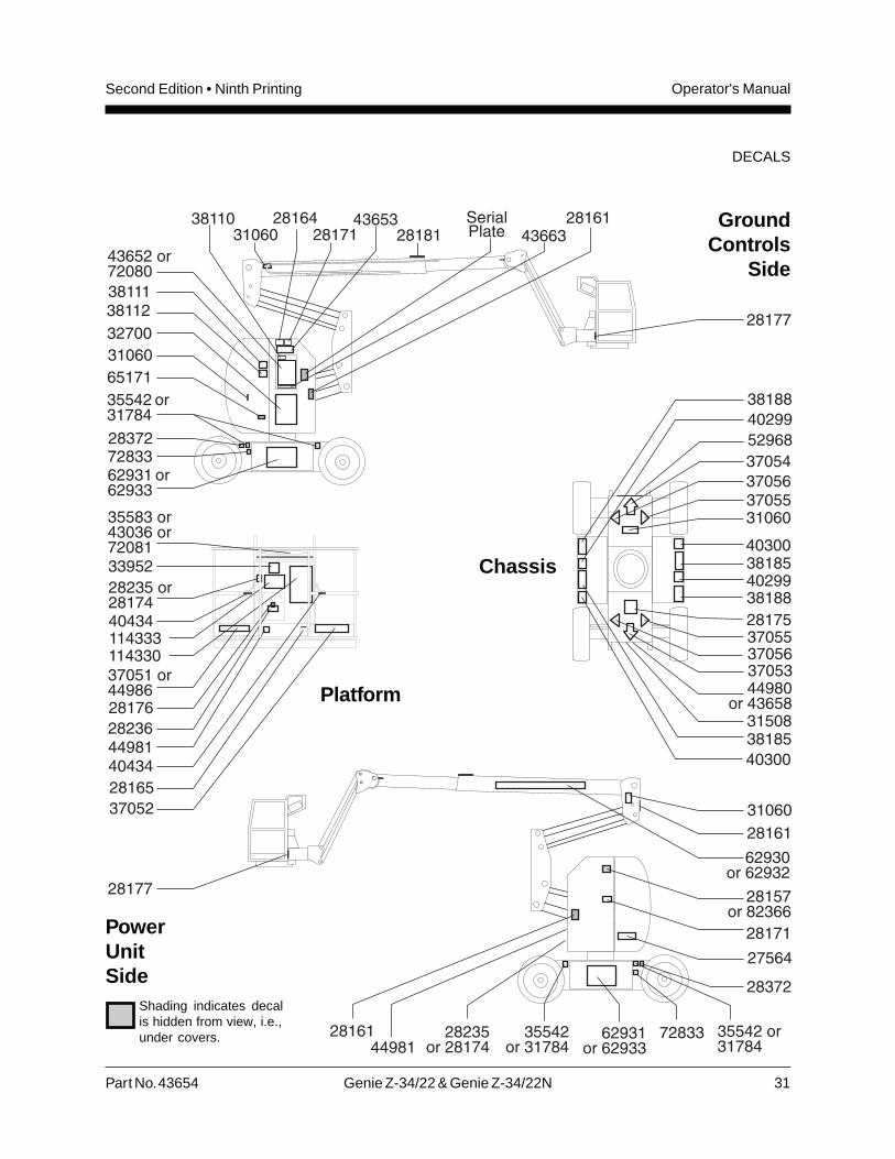
Decal Inspection
Use the pictures on the next page to verify that alldecals are legible and in place.
Below is a numerical list with quantities anddescriptions.
Part No. 43654 Genie Z-34/22 & Genie Z-34/22N 31
Operator's ManualSecond Edition • Ninth Printing
DECALS
GroundControls
Side
PowerUnitSide
Shading indicates decalis hidden from view, i.e.,under covers.
Platform
Chassis
32 Genie Z-34/22 & Genie Z-34/22N Part No. 43654
Operator's Manual Second Edition • Ninth Printing
Specifications
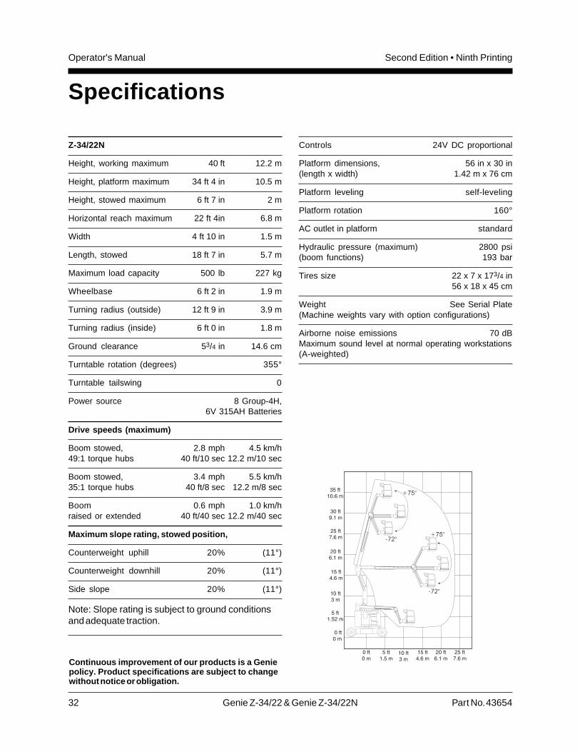
Z-34/22N
Height, working maximum 40 ft 12.2 m
Height, platform maximum 34 ft 4 in 10.5 m
Height, stowed maximum 6 ft 7 in 2 m
Horizontal reach maximum 22 ft 4in 6.8 m
Width 4 ft 10 in 1.5 m
Length, stowed 18 ft 7 in 5.7 m
Maximum load capacity 500 lb 227 kg
Wheelbase 6 ft 2 in 1.9 m
Turning radius (outside) 12 ft 9 in 3.9 m
Turning radius (inside) 6 ft 0 in 1.8 m
Ground clearance 53/4 in 14.6 cm
Turntable rotation (degrees) 355°
Turntable tailswing 0
Power source 8 Group-4H,6V 315AH Batteries
Drive speeds (maximum)
Boom stowed, 2.8 mph 4.5 km/h49:1 torque hubs 40 ft/10 sec 12.2 m/10 sec
Boom stowed, 3.4 mph 5.5 km/h35:1 torque hubs 40 ft/8 sec 12.2 m/8 sec
Boom 0.6 mph 1.0 km/hraised or extended 40 ft/40 sec 12.2 m/40 sec
Maximum slope rating, stowed position,
Counterweight uphill 20% (11°)
Counterweight downhill 20% (11°)
Side slope 20% (11°)
Note: Slope rating is subject to ground conditionsand adequate traction.
Controls 24V DC proportional
Platform dimensions, 56 in x 30 in(length x width) 1.42 m x 76 cm
Platform leveling self-leveling
Platform rotation 160°
AC outlet in platform standard
Hydraulic pressure (maximum) 2800 psi(boom functions) 193 bar
Tires size 22 x 7 x 173/4 in56 x 18 x 45 cm
Weight See Serial Plate(Machine weights vary with option configurations)
Airborne noise emissions 70 dBMaximum sound level at normal operating workstations(A-weighted)
Continuous improvement of our products is a Geniepolicy. Product specifications are subject to changewithout notice or obligation.
Part No. 43654 Genie Z-34/22 & Genie Z-34/22N 33
Operator's ManualSecond Edition • Ninth Printing
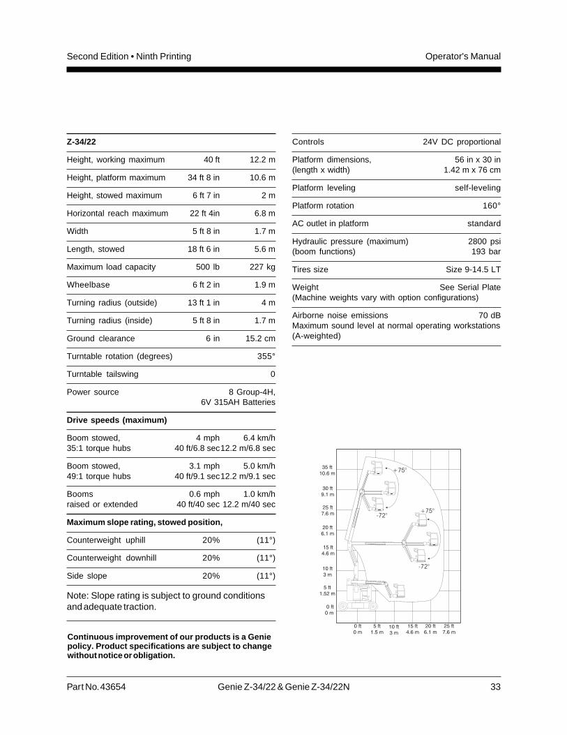
Z-34/22
Height, working maximum 40 ft 12.2 m
Height, platform maximum 34 ft 8 in 10.6 m
Height, stowed maximum 6 ft 7 in 2 m
Horizontal reach maximum 22 ft 4in 6.8 m
Width 5 ft 8 in 1.7 m
Length, stowed 18 ft 6 in 5.6 m
Maximum load capacity 500 lb 227 kg
Wheelbase 6 ft 2 in 1.9 m
Turning radius (outside) 13 ft 1 in 4 m
Turning radius (inside) 5 ft 8 in 1.7 m
Ground clearance 6 in 15.2 cm
Turntable rotation (degrees) 355°
Turntable tailswing 0
Power source 8 Group-4H,6V 315AH Batteries
Drive speeds (maximum)
Boom stowed, 4 mph 6.4 km/h35:1 torque hubs 40 ft/6.8 sec12.2 m/6.8 sec
Boom stowed, 3.1 mph 5.0 km/h49:1 torque hubs 40 ft/9.1 sec12.2 m/9.1 sec
Booms 0.6 mph 1.0 km/hraised or extended 40 ft/40 sec 12.2 m/40 sec
Maximum slope rating, stowed position,
Counterweight uphill 20% (11°)
Counterweight downhill 20% (11°)
Side slope 20% (11°)
Note: Slope rating is subject to ground conditionsand adequate traction.
Controls 24V DC proportional
Platform dimensions, 56 in x 30 in(length x width) 1.42 m x 76 cm
Platform leveling self-leveling
Platform rotation 160°
AC outlet in platform standard
Hydraulic pressure (maximum) 2800 psi(boom functions) 193 bar
Tires size Size 9-14.5 LT
Weight See Serial Plate(Machine weights vary with option configurations)
Airborne noise emissions 70 dBMaximum sound level at normal operating workstations(A-weighted)
Continuous improvement of our products is a Geniepolicy. Product specifications are subject to changewithout notice or obligation.
Genie North America
Genie Australia Pty Ltd.
Genie China
Genie Malaysia
Genie Japan
Genie Korea
Genie Brasil
Genie Holland
PhoneToll Free
Fax
Phone +Fax +
Phone +Fax +
Phone +Fax +
Phone +Fax +
Phone +Fax +
Phone +Fax +
Phone +Fax +
425.881.1800USA and Canada800.536.1800425.883.3475
61 7 3375 166061 7 3375 1002
86 21 5385257086 21 53852569
65 98 480 77565 67 533 544
81 3 3453 608281 3 3453 6083
82 25 587 26782 25 583 910
55 11 41 665 75555 11 41 665 754
31 183 581 10231 183 581 566
Genie Scandinavia
Genie France
Genie Iberica
Genie Germany
Genie U.K.
Genie Mexico City
Phone +Fax +
Phone +Fax +
Phone +Fax +
Phone +Fax +
Phone +Fax +
Phone +Fax +
46 31 575100
33 (0)2 37 26 09 9933 (0)2 37 26 09 98
34 93 579 504234 93 579 5059
49 (0)4202 8852049 (0)4202 8852-20
44 (0)1476 58433344 (0)1476 584334
52 55 5666 524252 55 5666 3241
46 31 579020