Embed Size (px)
Citation preview

IQENOPS310300 Version 1 Issue 6 0.1
Operator’sManual
© March 2000
Snell & Wilcox Ltd, Durford Mill, Petersfield, Hampshire, GU315AZ, United Kingdom.Tel:+44(0)1730 821188. Fax:+44(0)1730 821199.
Modular System
IQENOPS310300 Version 1 Issue 6 0.2
Information Concerning this Manual
This manual contains information for the KUDOS IQ Modular System mainframes and information for specificmodules.
If specifically ordered, this manual could be supplied containing operating information for all modules currentlyavailable plus previous versions of modules or deleted products.
When a mainframe is supplied with particular modules installed, only operational information for those moduleswill be found in this manual and each module will have a dedicated numbered section as shown in the Table ofContents.
If, at a later date, other types of modules are supplied and installed, the operational information section forthose modules will be supplied. The sheets will be ready hole-punched and should be fitted into this manualbinder in the appropriately numbered section.
Update/revision sheets should replace existing pages when supplied by the agent or Snell & Wilcox Ltd.
(Note that the last six numbers of the text in the lower left hand corner of the page, is the release date of thatrevision in day, month, year sequence)
Important Notice
To fully conform to EMC standards as specified on page 4 of this section, modules must be installed asspecified in Section 1, page 1.2
No responsibility is taken by the manufacturer or supplier for any non-compliance to EMC standards due toincorrect installation.

IQENOPS310300 Version 1 Issue 6 0.3
Safety WarningsAlways ensure that the unit is properly earthed and power connections correctly made.
This equipment shall be supplied from a power system providing a PROTECTIVE EARTH connection andhaving a neutral connection which can be reliably identified.
The power terminals of the IEC mains input connector on the rear panel areidentified as shown below:
E = Protective Earth Conductor
N = Neutral Conductor
L = Live Conductor
Power cable supplied for countries other than the USAThe equipment is normally shipped with a power cable with a standard IEC moulded free socket on one endand a standard IEC moulded plug on the other. If you are required to remove the moulded mains supply plug,dispose of the plug immediately in a safe manner. The colour code for the lead is as follows:
GREEN/YELLOW lead connected to E (Protective Earth Conductor)BLUE lead connected to N (Neutral Conductor)BROWN lead connected to L (Live Conductor)
Power cable supplied for the USAThe equipment is shipped with a power cord with a standard IEC moulded free socket on one end and astandard 3-pin plug on the other. If you are required to remove the moulded mains supply plug, dispose of theplug immediately in a safe manner. The colour code for the lead is as follows:
GREEN lead connected to E (Protective Earth Conductor)WHITE lead connected to N (Neutral Conductor)BLACK lead connected to L (Live Conductor)
The terminals of the IEC mains supplylead are identified as shown opposite:
Note that for equipment that is not fitted with a mains power switch, to comply with BS60950 Clauses 1.7.2 and2.6.9, the power outlet supplying power to the unit should be close to the unit and easily accessible.
Warnings Voltages within this unit can be lethal under certain circumstances. Where poweris required to be connected to the unit during servicing great care must be takento avoid contact with these voltages.
Maintenance should only be carried out by suitably qualified personnel.
No part of this publication may be transmitted or reproduced in any form or by any means, electronic ormechanical, including photocopy, recording or any information storage and retrieval system, without permissionbeing granted, in writing, by the publishers or their authorised agents.

IQENOPS310300 Version 1 Issue 6 0.4
EMC Standards
This unit has been designed to comply with the following standards:
Electromagnetic Compatibility-Generic Immunity Standard BS EN 50082-1:1992
The European Standard EN 50082-1:1992 has the status of a British Standard and is related to EuropeanCouncil Directive 89/336/EEC dated 3rd May 1989.
Electromagnetic Compatibility-Generic Emission Standard BS EN 50081-1:1992
The European Standard EN 50081-1:1992 has the status of a British Standard and is related to EuropeanCouncil Directive 89/336/EEC dated 3rd May 1989.
Safety Standards
This unit has been designed to comply with EN60950:1992 as amended by amendmentA1(May 1993) and amendment A2(March 1994). Specification for safety of technologyequipment, including electrical business equipment.
EMC Performance of Cables and Connectors
Snell & Wilcox products are designed to meet or exceed the requirements of the appropriate European EMCstandards. In order to achieve this performance in real installations it is essential to use cables and connectorswith good EMC characteristics.
All signal connections (including remote control connections) shall be made with screened cables terminated inconnectors having a metal shell. The cable screen shall have a large-area contact with the metal shell.
COAXIAL CABLES
Coaxial cables connections (particularly serial digital video connections) shall be made with high-qualitydouble-screened coaxial cables such as Belden 8281 or BBC type PSF1/2M.
D-TYPE CONNECTORS
D-type connectors shall have metal shells making good RF contact with the cable screen. Connectors having"dimples" which improve the contact between the plug and socket shells, are recommended.
CAUTION: These servicing instructions are for use by qualified personnel only. To reducethe risk of electric shock, do not perform any servicing other than that contained in theOperating Instructions unless you are qualified to do so. Refer all servicing to qualifiedservice personnel.

IQENOPS310300 Version 1 Issue 6 0.5
Packing List
The unit is supplied in a dedicated packing carton provided by the manufacturer and should not be accepted ifdelivered in inferior or unauthorised materials. Carefully unpack the carton and check for any shipping damageor shortages.
Any shortages or damage should be reported to the supplier immediately.
Enclosures:• Mainframe• Power cable
• Module(s)• Operator’s Handbook(s)
IQENOPS310300 Version 1 Issue 6 0.6
Table of Contents
SECTION Page
1 The Kudos IQ Modular System
General Concept: 1U and 3U Systems ..............................................................................1.1
RollCall Remote Control System and Computer Control System........................................1.4
Specifications
All Mainframes .......................................................................................................1.8
Installation
1U Mainframe.........................................................................................................1.9
3U Mainframe (Single Power Supply) ....................................................................1.11
3U Mainframe (Dual Power Supplies)....................................................................1.13
Operation
1U Active Front Panel ............................................................................................1.16
Control System Overview.......................................................................................1.33
2 Analogue Video Distribution
IQAVDA-1 3 Output distribution amplifier with equalisation.................................2.1
IQAVDA-2 8 Output distribution amplifier with equalisation.................................2.1
IQAVDR-1/-2 10/4 Output distribution amplifiers with EQ and RollCall control........2b.1
3 Serial Digital Video Distribution
IQDSDA-1 4 output amplifier with equalisation and buffer (not re-clocking) .......3.1
IQDSDA-2 8 output amplifier with equalisation and buffer (not re-clocking) ........3.1
4 Digital Video Converters: Parallel to Serial
IQDPS-1 D1/D2 parallel to serial 1 output.........................................................4.1
IQDPS-2 D1/D2 parallel to serial 7 outputs.......................................................4.1
5 Digital Video Converters: Serial to Parallel
IQDSP-1 D1/D2 serial to 1 parallel and 1 re-clocked serial output....................5.1
IQDSP-2 D1/D2 serial to 1 parallel and 6 re-clocked serial outputs..................5.1
6 Digital Serial Distribution Amplifiers
IQDSDR-1D1/D2 4 output serial distribution amplifier with equalisation,buffer and re-clocking ........................................................................6.1
IQDSDR-2 D1/D2 8 output serial distribution amplifier with equalisation,buffer and re-clocking ........................................................................6.1
IQDDASI-1 SDI/ASI 4 output re-clocking distribution amplifier .............................6a.1
IQDSDR/-R Re-clocking SDA,s, 5/10 output and RollCall versions. .....................6b.1
IQDAVM Re-clocking SDA + Audio and Composite Video Monitor ..................6c.1
IQENOPS310300 Version 1 Issue 6 0.7
7 Black Burst Generators: Fixed Standard
IQABBP-1-P Analogue PAL 5 output 10ppm ..........................................................7.1
IQABBP-2-P Analogue PAL 10 output 10ppm ........................................................7.1
IQABBP-1-N Analogue NTSC 5 output 10ppm .......................................................7.1
IQABBP-2-N Analogue NTSC 10 output 10ppm .....................................................7.1
8 Black Burst Generators: Multi-Standard
IQADBB-1-0 3 Standard 4 output ...........................................................................8a.1
IQADBB-2-0 3 Standard 8 output ...........................................................................8a.1
IQADBB-1-S 3 Standard 4 output 1 ppm ................................................................8a.1
IQADBB-2-S 3 Standard 8 output 1 ppm ................................................................8a.1
IQADBBG Multi-Standard Genlockable ..............................................................8b.1
9 D1 Pattern Generators
IQD1MPG-2 D1 Master pattern generator (over 60 patterns), analogue/D1/slavegenlock and freerun (10ppm), 6 outputs + D1 reference output ........9.1
10 Analogue Decoders
IQAAD-1-P Advanced analogue decoderPAL Composite to Y,Pr,Pb or GBR 1 output......................................10a.1
IQAAD-2-P Advanced analogue decoderPAL Composite to Y,Pr,Pb or GBRS 2 outputs .................................10a.1
IQAAD-1-N Advanced analogue decoderNTSC Composite to Y,Pr,Pb or GBR 1 output...................................10a.1
IQAAD-2-N Advanced analogue decoderNTSC Composite to Y,Pr,Pb or GBRS 2 outputs ..............................10a.1
IQD1AAD-2-P-10F Advanced analogue decoder PAL Composite to Y,Pr,Pb and D110-Bit with near 601 filters .................................................................10b.1
IQD1AAD-2-N-10F Advanced analogue decoderNTSC Composite to Y,Pr,Pb and D1 10-Bit with near 601filters .......10b.1
11 Encoders
IQD1SDE-1 D1 serial to PAL/NTSC composite and serial re-clocked outputs ......11.1
IQD1SDE-2 D1 serial to PAL/NTSC composite and serial re-clocked outputs ......11.1
IQD1GEN-1 Genlockable D1 serial to PAL/NTSCcomposite/serial re-clocked outputs...................................................11.9
IQD1GEN-2 Genlockable D1 serial to PAL/NTSCcomposite/serial re-clocked outputs...................................................11.9
IQDMSE-1 Multi-Standard D1 Digital Encoder.....................................................11.17
IQDMSE-2 Multi-Standard D1 Digital Encoder composite and serial outputs ......11.17
12 D to A Converters
IQD1DAC-1-0 Digital serial to YPbPrS or GBRS with 601 filters 10-Bit ....................12.1
IQD1DAC-2-0 Digital serial to YPbPrS or GBRS with 601 filters10-Bit+2 serial outputs .......................................................................12.1
IQD1DAC-1-F Digital serial to YPbPrS or GBRS with near 601 filters10-Bit.............12.1
IQD1DAC-2-F Digital serial to YPbPrS or GBRS10-Bit+2 serial outputs ..................12.1
IQENOPS310300 Version 1 Issue 6 0.8
14 A to D Converters
IQD1ADC-1-10 YPbPr or GBR to D1 10-Bit 601 filters 2 output .................................14.1
IQD1ADC-2-10 YPbPr or GBR to D1 10-Bit 601 filters 2 output + ref input ................14.1
IQD1ADC-1-10F YPbPr or GBR to D1 10-Bit near 601 filters 2 output.........................14.1
IQD1ADC-2-10F YPbPr or GBR to D1 10-Bit near 601 filters 2 output + ref input........14.1
IQD1ADC-1-8F YPbPr or GBR to D1 8-Bit near 601 filters 2 output...........................14.1
IQD1ADC-2-8F YPbPr or GBR to D1 8-Bit near 601 filters 2output + ref input...........14.1
15 D1 Black Generators
IQD1BPG-1 D1 Slave black generator, slave/analogue genlock andfreerun (10ppm), 3 outputs; includes EDH output codes ...................15.1
IQD1BPG-2 D1 Slave black generator,slave/analogue genlock andfreerun (10ppm), 3 outputs; includes EDH output codes ...................15.1
16 D1 Line-based Pattern Generators
IQD1LPG-1 D1 Line-based pattern generator, slave/analogue genlockand freerun (10ppm) 3 outputs ..........................................................16.1
IQD1LPG-2 D1 Line-based pattern generator, slave/analogue genlockand freerun (10ppm) 6 outputs ..........................................................16.1
17 D1 Frame-Based Pattern Generators
IQD1FPG-1 D1 Frame-based pattern generator, slave/analogue genlockand freerun (10ppm) 3 outputs ..........................................................17.1
IQD1FPG-2 D1 Frame-based pattern generator, slave/analogue genlockand freerun (10ppm) 6 outputs ..........................................................17.1
18 EDH Related Products
IQD1MON-1 EDH monitor/inserter with Gamut/Legal Signal checker 3 outputs ....18a.1
IQD1MON-2 EDH monitor/inserter with Gamut/Legal Signal checker 4 outputs ....18a.1
IQD1EDH-1 EDH monitor/inserter 3 outputs..........................................................18b.1
IQD1EDH-2 EDH monitor/inserter 4 outputs..........................................................18b.1
19 Line Synchronisers
IQD1LSY-1 D1 Line Synchroniser 2 output...........................................................19.1
IQD1LSY-2 D1 Line Synchroniser 4 Output..........................................................19.1
20 Frame Synchronisers
IQD1FSY-1-0 D1 Frame Synchroniser + Variable Delay 2 output............................20.1
IQD1FSY-2-0 D1 Frame Synchroniser + Variable Delay 4 output............................20.1
IQD1FSY-1-D D1 Frame Synchroniser + Variable Delay andextended delay mode (2 frame) 2 output ...........................................20.1
IQD1FSY-2-D D1 Frame Synchroniser + Variable Delay andextended delay mode (2 frame) 4 output ...........................................20.1
21 Switchers
IQDMX4-1-0 4 input D1/2 switch.............................................................................21.1
IQDMX4-1-E 4 input D1/2 switch with EDH insertion ..............................................21.1
IQDMX8-2-0 8 input D1/2 switch.............................................................................21.1
IQDMX8-2-E 8 input D1/2 switch with EDH insertion ..............................................21.1

IQENOPS310300 Version 1 Issue 6 0.9
22 Miscellaneous
23 Audio Analogue to Digital Converters
IQBADC 2 Channel Audio Analogue to Digital Converter.................................23.1
IQBADCD 4 Channel Audio Analogue to Digital Converter (with Delay).............23a.1
IQBADCS 2 Channel Audio Analogue to Digital Converter (delay & vari gain)...23b.1
IQBADCD 4 Channel Audio Analogue to Digital Converter (no Delay) ...............23c.1
24 Digital Audio Delay
IQBDAD 2 Channel Digital Audio Delay ...........................................................24.1
25 Analogue Audio Delay
IQBAAD 2 Channel Analogue Audio Delay ......................................................25.1
26 Digital to Analogue Converters
IQBDAC 2 Channel Audio Digital to Analogue Converter (with delay) .............26.1
27 Inserters
IQBAIR AES/EBU Audio Inserter ....................................................................27a.1
IQBAAI Inserter Analog Audio to 4:2:2 ...........................................................27b.1
IQBAIRS AES/EBU Audio Inserter with gain control .........................................27c.1
IQBAI 4x AES/EBU Audio Inserter ...............................................................27d.1
IQBADI 4 Analog and 2 AES/EBU Audio Inserter ...........................................27e.1
28 Extractors
IQBAX AES/EBU Audio Extractor + SDI outputs ...........................................28.1
IQBAXR AES/EBU Audio Extractor ..................................................................28a.1
IQBAAX Extractor 4:2:2 to Analog Audio + SDI outputs ..................................28b.1
IQBADX Extractor 4:2:2 to 4 Analog and 4 AES Audio + SDI outputs .............28c.1
29 Digital Audio Synchronisers
IQBSYN Digital Audio Synchroniser .................................................................29.1
IQBSYD Dual Digital Audio Synchroniser with 2 x 2 Router.............................29a.1
30 Digital Decoders
IQDMSDD Multi-standard decoder crystal lock....................................................30a.1
IQDMSDN Multi-standard decoder crystal lock with noise reduction...................30b.1
IQDMSDA Multi-standard decoder with synchroniser and all standards .............30c.1
IQDMSDS Multi-standard decoder ......................................................................30d.1
IQDMSDP Multi-standard decoder SDI Outputs..................................................30e.1
31 New Audio Modules
IQBDDAS Digital Audio Distribution Amplifier .....................................................31a.1
IQBMX3 3 x1 Router and Monitor ....................................................................31b.1
IQBSFR Audio Shuffler with Stereo Combiner.................................................31c.1
IQBAR Digital Audio Reference Generator ....................................................31d.1
IQENOPS310300 Version 1 Issue 6 0.10
32 Video Processing
IQDNRS SDI Noise Reducer ............................................................................32.1
IQDPF Digital Picture Fixer ............................................................................32a.1
33 RollCall™
IQCGPI-1 RollCall general purpose interface.....................................................33a
IQCGPI-2 RollCall general purpose interface.....................................................33a
IQCCPC RollCallPC interface card...................................................................33b
IQCSPI-1 RollCall serial port interface ...............................................................33c
IQCSPI-2 RollCall serial port interface ...............................................................33c
IQCBRG-1-0 RollCall network bridge ......................................................................33d
IQCBRG-2-M RollCall network bridge with additional RS232/Modem port ..............33d
IQRSAD RollCall serial adapter ........................................................................33e
34 Software
IQSPCR RollCall PC control software (Windows)
IQSPCD RollCall PC error logging software with data logging
35 Digital Audio Distribution Amplifiers
IQBDDAD Dual Digital Audio Distribution Amplifier.............................................35.1
36 Analog Audio Distribution Amplifiers
IQBDA3S Analog Audio Distribution Amplifier 2 inputs, 3 outputs per input ......36.1
IQBDA4 Analog Audio Distribution Amplifier 1 input, 4 outputs .......................36a.1
IQBDA7 Analog Audio Distribution Amplifier 1 input, 7 outputs .......................36b.1
37 Aspect Ratio Converters
IQDARCM Fixed Mode Aspect Ratio Converter ..................................................37.1
38 Fibre Optic Modules
IQORXD Dual-channel fibre optic receiver for SDI ...........................................38a.1
IQOTXD Dual-channel, multimode (MM) fibre optic transmitter for SDI ...........38b.1
39 Logo Inserter
IQDLOG SDI Logo Inserter...............................................................................39.1
IQENOPS310300 Version 1 Issue 6 0.11
40 MPEG ASI Infrostructure
IQMDDA ASI Distribution Amplifier ...................................................................40a.1
IQMDDM ASI Distribution Amplifier and Stream Monitor...................................40b.1
IQMMX2 ASI 2 x 1 Router.................................................................................40c.1
IQENOPS310300 Version 1 Issue 6 0.12
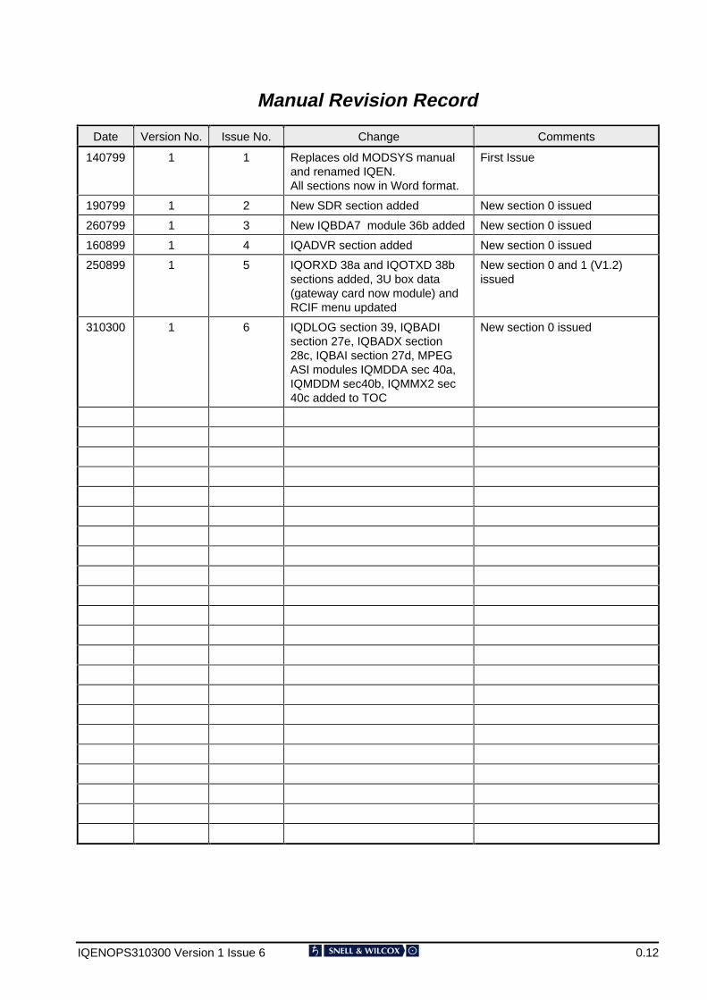
Manual Revision Record
Date Version No. Issue No. Change Comments
140799 1 1 Replaces old MODSYS manualand renamed IQEN.All sections now in Word format.
First Issue
190799 1 2 New SDR section added New section 0 issued
260799 1 3 New IQBDA7 module 36b added New section 0 issued
160899 1 4 IQADVR section added New section 0 issued
250899 1 5 IQORXD 38a and IQOTXD 38bsections added, 3U box data(gateway card now module) andRCIF menu updated
New section 0 and 1 (V1.2)issued
310300 1 6 IQDLOG section 39, IQBADIsection 27e, IQBADX section28c, IQBAI section 27d, MPEGASI modules IQMDDA sec 40a,IQMDDM sec40b, IQMMX2 sec40c added to TOC
New section 0 issued
The .8'26 ,4 Modular System SECTION 1
IQENOPS250899 Version 1 Issue 2 1.1
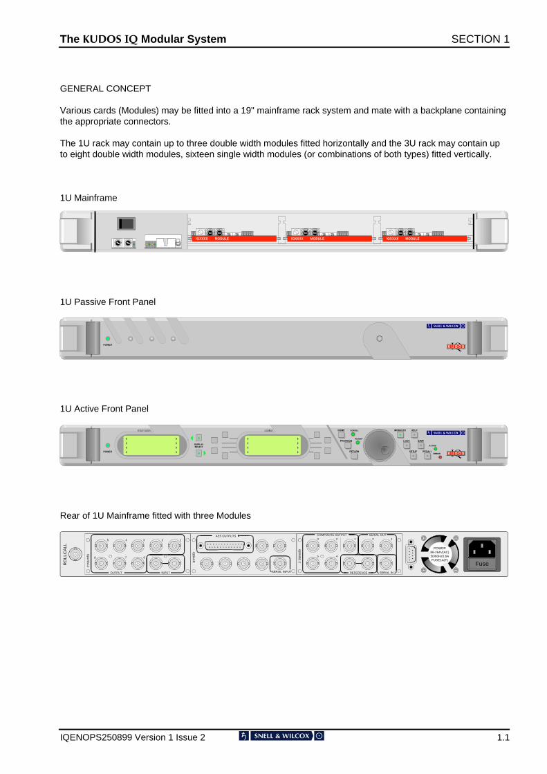
GENERAL CONCEPT
Various cards (Modules) may be fitted into a 19" mainframe rack system and mate with a backplane containingthe appropriate connectors.
The 1U rack may contain up to three double width modules fitted horizontally and the 3U rack may contain upto eight double width modules, sixteen single width modules (or combinations of both types) fitted vertically.
1U Mainframe
1U Passive Front Panel
1U Active Front Panel
Rear of 1U Mainframe fitted with three Modules
FuseRO
LLC
ALL POWER
88-264V(AC)50/60Hz0.6AFUSE1A(T)
OUTPUT INPUT
IQA
VD
A-2
4 1235
7 68
IQB
AX
R
SERIAL INPUT
AES OUTPUTS COMPOSITE OUTPUT
REFERENCE SERIAL IN
IQD
MS
E-2
SERIAL OUT
1 2 1 2 3
4 5
The .8'26 ,4 Modular System SECTION 1
IQENOPS250899 Version 1 Issue 2 1.2
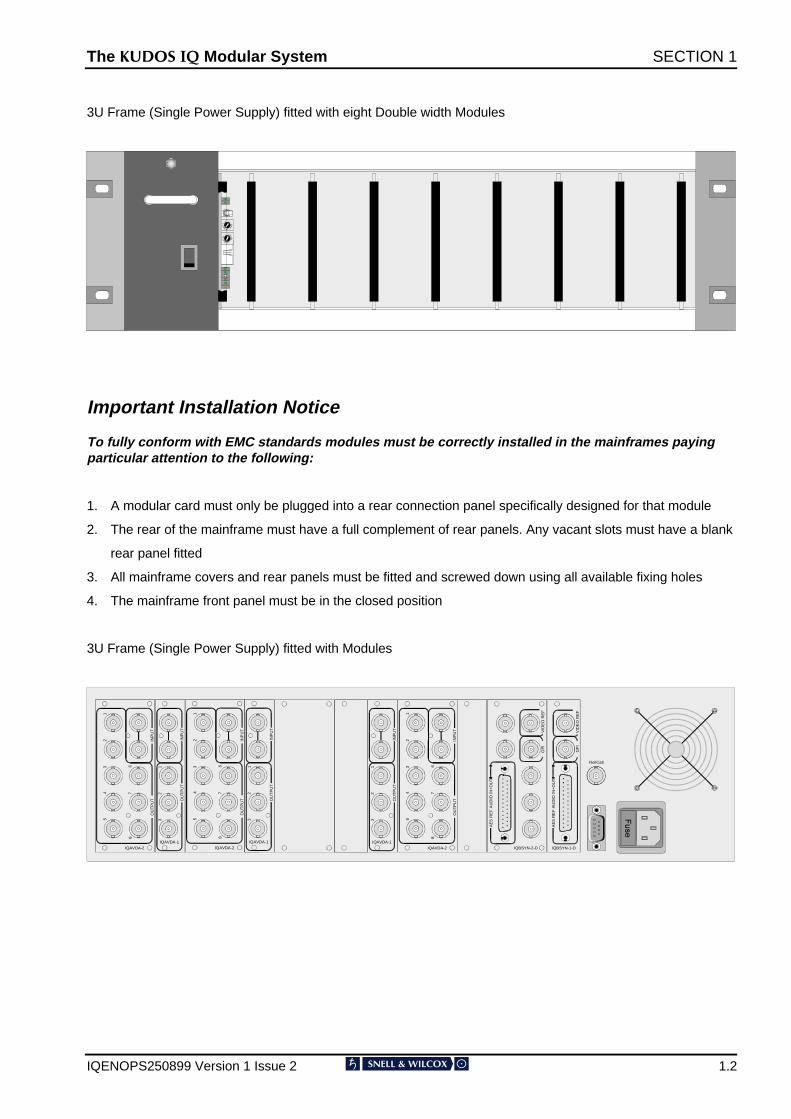
3U Frame (Single Power Supply) fitted with eight Double width Modules
Important Installation Notice
To fully conform with EMC standards modules must be correctly installed in the mainframes payingparticular attention to the following:
1. A modular card must only be plugged into a rear connection panel specifically designed for that module
2. The rear of the mainframe must have a full complement of rear panels. Any vacant slots must have a blank
rear panel fitted
3. All mainframe covers and rear panels must be fitted and screwed down using all available fixing holes
4. The mainframe front panel must be in the closed position
3U Frame (Single Power Supply) fitted with Modules
OU
TP
UT
INP
UT
IQAVDA-2
41
23
5
76
8
OU
TP
UT
IQAVDA-1
12
3
INP
UT
OU
TP
UT
IQAVDA-1
12
3
INP
UT
OU
TP
UT
INP
UT
IQAVDA-2
41
23
5
76
8
OU
TP
UT
IQAVDA-1
12
3
INP
UT
OU
TP
UT
INP
UT
IQAVDA-2
41
23
5
76
8
RollCall
IQBSYN-2-D
AE
S R
EF
AU
DIO
IN+
OU
T
VID
EO
RE
FG
PI
IQBSYN-1-D
VID
EO
RE
F
AE
S R
EF
AU
DIO
IN
+O
UT
GP
I
The .8'26 ,4 Modular System SECTION 1
IQENOPS250899 Version 1 Issue 2 1.3
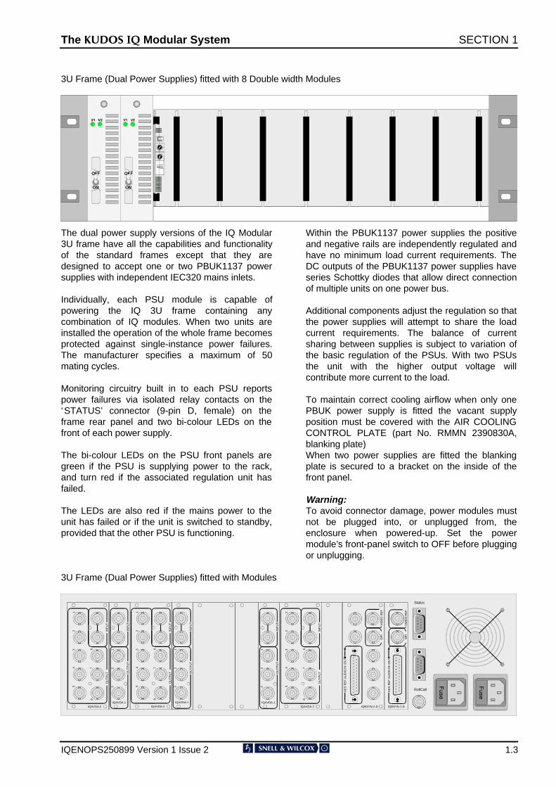
3U Frame (Dual Power Supplies) fitted with 8 Double width Modules
The dual power supply versions of the IQ Modular3U frame have all the capabilities and functionalityof the standard frames except that they aredesigned to accept one or two PBUK1137 powersupplies with independent IEC320 mains inlets.
Individually, each PSU module is capable ofpowering the IQ 3U frame containing anycombination of IQ modules. When two units areinstalled the operation of the whole frame becomesprotected against single-instance power failures.The manufacturer specifies a maximum of 50mating cycles.
Monitoring circuitry built in to each PSU reportspower failures via isolated relay contacts on the‘STATUS’ connector (9-pin D, female) on theframe rear panel and two bi-colour LEDs on thefront of each power supply.
The bi-colour LEDs on the PSU front panels aregreen if the PSU is supplying power to the rack,and turn red if the associated regulation unit hasfailed.
The LEDs are also red if the mains power to theunit has failed or if the unit is switched to standby,provided that the other PSU is functioning.
Within the PBUK1137 power supplies the positiveand negative rails are independently regulated andhave no minimum load current requirements. TheDC outputs of the PBUK1137 power supplies haveseries Schottky diodes that allow direct connectionof multiple units on one power bus.
Additional components adjust the regulation so thatthe power supplies will attempt to share the loadcurrent requirements. The balance of currentsharing between supplies is subject to variation ofthe basic regulation of the PSUs. With two PSUsthe unit with the higher output voltage willcontribute more current to the load.
To maintain correct cooling airflow when only onePBUK power supply is fitted the vacant supplyposition must be covered with the AIR COOLINGCONTROL PLATE (part No. RMMN 2390830A,blanking plate)When two power supplies are fitted the blankingplate is secured to a bracket on the inside of thefront panel.
Warning:To avoid connector damage, power modules mustnot be plugged into, or unplugged from, theenclosure when powered-up. Set the powermodule’s front-panel switch to OFF before pluggingor unplugging.
3U Frame (Dual Power Supplies) fitted with Modules
OU
TP
UT
INP
UT
IQAVDA-2
41
23
5
76
8
OU
TP
UT
IQAVDA-1
12
3
INP
UT
OU
TP
UT
IQAVDA-1
12
3
INP
UT
OU
TP
UT
INP
UT
IQAVDA-2
41
23
5
76
8
OU
TP
UT
IQAVDA-1
12
3
INP
UT
OU
TP
UT
INP
UT
IQAVDA-2
41
23
5
76
8
RollCall
IQBSYN-2-D
AE
S R
EF
AU
DIO
IN+
OU
T
VID
EO
RE
FG
PI
IQBSYN-1-D
VID
EO
RE
F
AE
S R
EF
AU
DIO
IN
+O
UT
GP
I
Status
The .8'26 ,4 Modular System SECTION 1
IQENOPS250899 Version 1 Issue 2 1.4
Control Panels
A mainframe and the modules that it contains, may be controlled by the following methods:-
1. Locally, by use of an active front panel (the control panel) for the 1U system
2. Remotely, by use the same control panel as in (1) above, connected by a single cable assembly
3. Remotely, from any number of control panels (1U), connected via the RollCall communications network
4. For units not equipped with RollCall preset controls and switches are provided on the front of each module,
accessible behind the drop-down front panel.
The RollCall Communications System and Computer Control System
RollCall remote control gives a uniquely powerful and flexible operating system that can be as simple as asingle rack unit with control panel, or a powerful multi-master, multi-slave configuration with the PCcontrollability for full station automation.
The RollCall command protocol derives control panel operating software from the IQ module being addressed.This unique feature ensures that module updates or additions will not require control system software upgrades- simply plug in and switch on.
For modules with the RollCall option fitted all card edge control functions are available on the remote controlpanel or any other controlling device. For some module cards additional control functions and readouts will beavailable to the RollCall panel but will not be accessible via the card edge controls.
Note that for some modules if any of the preset switches mentioned above are set to the ON position, it will notbe possible for the function to be disabled by the remote control mechanism. Under these circumstances amessage will be displayed on the active remote control panel indicating that control is not available. To avoidthis situation it is recommended that all card edge preset switches be set to the OFF position.
When the unit (or module) is powered-up the module will normally assume the same set-up conditions thatexisted at the last power-down. This information is provided by the non-volatile memory of the module’sdedicated Control Processing Unit under the control of RollCall. Some modules incorporate methods that allowother set-up conditions to exist on power-up; please consult the information specific to each module for details.
The .8'26 ,4 Modular System SECTION 1
IQENOPS250899 Version 1 Issue 2 1.5
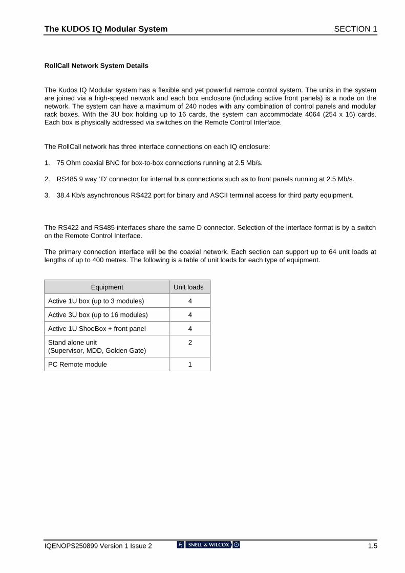
RollCall Network System Details
The Kudos IQ Modular system has a flexible and yet powerful remote control system. The units in the systemare joined via a high-speed network and each box enclosure (including active front panels) is a node on thenetwork. The system can have a maximum of 240 nodes with any combination of control panels and modularrack boxes. With the 3U box holding up to 16 cards, the system can accommodate 4064 (254 x 16) cards.Each box is physically addressed via switches on the Remote Control Interface.
The RollCall network has three interface connections on each IQ enclosure:
1. 75 Ohm coaxial BNC for box-to-box connections running at 2.5 Mb/s.
2. RS485 9 way ‘D’ connector for internal bus connections such as to front panels running at 2.5 Mb/s.
3. 38.4 Kb/s asynchronous RS422 port for binary and ASCII terminal access for third party equipment.
The RS422 and RS485 interfaces share the same D connector. Selection of the interface format is by a switchon the Remote Control Interface.
The primary connection interface will be the coaxial network. Each section can support up to 64 unit loads atlengths of up to 400 metres. The following is a table of unit loads for each type of equipment.
Equipment Unit loads
Active 1U box (up to 3 modules) 4
Active 3U box (up to 16 modules) 4
Active 1U ShoeBox + front panel 4
Stand alone unit(Supervisor, MDD, Golden Gate)
2
PC Remote module 1
The .8'26 ,4 Modular System SECTION 1
IQENOPS250899 Version 1 Issue 2 1.6
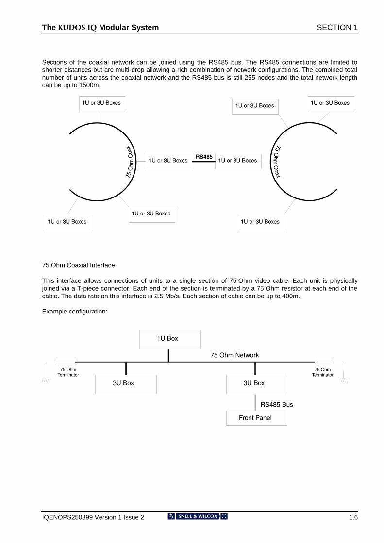
Sections of the coaxial network can be joined using the RS485 bus. The RS485 connections are limited toshorter distances but are multi-drop allowing a rich combination of network configurations. The combined totalnumber of units across the coaxial network and the RS485 bus is still 255 nodes and the total network lengthcan be up to 1500m.
75 Ohm Coaxial Interface
This interface allows connections of units to a single section of 75 Ohm video cable. Each unit is physicallyjoined via a T-piece connector. Each end of the section is terminated by a 75 Ohm resistor at each end of thecable. The data rate on this interface is 2.5 Mb/s. Each section of cable can be up to 400m.
Example configuration:
The .8'26 ,4 Modular System SECTION 1
IQENOPS250899 Version 1 Issue 2 1.7
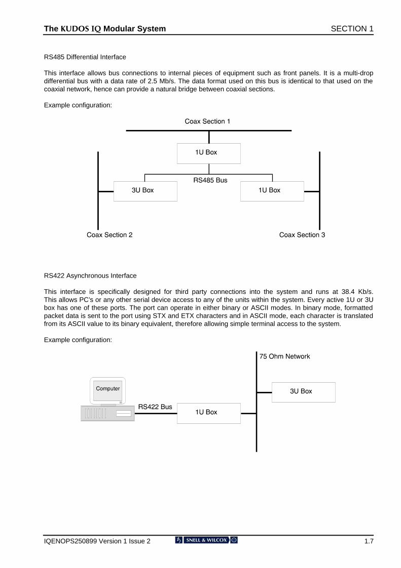
RS485 Differential Interface
This interface allows bus connections to internal pieces of equipment such as front panels. It is a multi-dropdifferential bus with a data rate of 2.5 Mb/s. The data format used on this bus is identical to that used on thecoaxial network, hence can provide a natural bridge between coaxial sections.
Example configuration:
RS422 Asynchronous Interface
This interface is specifically designed for third party connections into the system and runs at 38.4 Kb/s.This allows PC’s or any other serial device access to any of the units within the system. Every active 1U or 3Ubox has one of these ports. The port can operate in either binary or ASCII modes. In binary mode, formattedpacket data is sent to the port using STX and ETX characters and in ASCII mode, each character is translatedfrom its ASCII value to its binary equivalent, therefore allowing simple terminal access to the system.
Example configuration:
The .8'26 ,4 Modular System SECTION 1
IQENOPS250899 Version 1 Issue 2 1.8
TECHNICAL PROFILE
)HDWXUHV
,QSXWV�2XWSXWV5ROO&DOOu�5HPRWH&RQWURO
%1&�FRQQHFWRU
56��������5HPRWH&RQWURO
��SLQ�'�W\SH�FRQQHFWRU
$FWLYH�)URQW�3DQHO�&RQWUROV��QRW�IRU��8FDVH�'HGLFDWHG�3XVK%XWWRQV�IRU�+RPH3UHYLRXV5HWXUQ0RGXOHV/RFN6HWXS6DYH5HFDOO'LVSOD\�6HOHFW0HQX�7H[W�6HOHFW6SLQZKHHO�IRU�PHQXFRQWURO
3UHVHW�&RQWUROV8QLW�DGGUHVV�FRGHVHW�VZLWFKHV
��+H[�VZLWFKHV���WR�)
&RPPXQLFDWLRQVPRGH�VZLWFK
6HOHFW�5ROO&DOOu�����RU56����LQWHUIDFH
$GGLWLRQDO�&RQWUROV�YLD�5ROO&DOOu�5HPRWH&RQWURO�6\VWHP)XOO�&RQWURO�YLDDFWLYH�IURQW�SDQHO
6SHFLILFDWLRQV1XPEHU�RI�0RGXOHVWKDW�PD\�EHDFFRPPRGDWHG
6KRHER[��1RQH��XVH�ZLWKEODQN�RU�DFWLYH�IURQW�SDQHO�8�����GRXEOH�ZLGWK�W\SH��ILWWHG�KRUL]RQWDOO\�����VLQJOHZLGWK�%1&�W\SH��8����GRXEOH�ZLGWK�RU���VLQJOH�ZLGWK��RU�FRPELQDWLRQVRI�ERWK��ILWWHG�YHUWLFDOO\
0RGXOH�FDUGGLPHQVLRQV
����PP�ZLGH������PP�ORQJ�
0RGXOH�UHDUFRQQHFWRU
���ZD\�',1�����
0RGXOH�UHDU�SDQHOGLPHQVLRQV
������PP�ZLGH�������PP�GRXEOH�ZLGWK����PP��VLQJOH�ZLGWK��KLJK�
3RZHU�6KRHER[�,QSXW�9ROWDJH�5DQJH ����9�WR�����9�������+],QSXW�&RQQHFWRU ,(&����)XVHG�����$�7�3RZHU�6ZLWFK /RFDWHG�RQ�UHDU�SDQHO3RZHU�&RQVXPSWLRQ ���9$�PD[LPXP
3RZHU���8�%R[�,QSXW�9ROWDJH�5DQJH ���9�WR�����9�������+],QSXW�&RQQHFWRU ,(&����)XVHG���$�7�3RZHU�6ZLWFK %HKLQG�GURS�GRZQ�IURQW�SDQHO3RZHU�&RQVXPSWLRQ ���9$�PD[LPXP0RGXOHV�3RZHU'LVVLSDWLRQ
���:�PD[LPXP
2XWSXW �����9�DQG������9�����1RWH�WKDW�DOO�PRGXOHV�KDYHEXLOW�LQ�SRZHU�VXSSO\�IXVHV�
3RZHU���8�%R[�,QSXW�9ROWDJH�5DQJH ���9�WR�����9�������+],QSXW�&RQQHFWRU ,(&����)XVHG���$�7�3RZHU�6ZLWFK %HKLQG�GURS�GRZQ�IURQW�SDQHO3RZHU�&RQVXPSWLRQ ����9$�PD[LPXP0RGXOHV�3RZHU'LVVLSDWLRQ
����:�PD[LPXP
2XWSXW �����9�DQG������9�����1RWH�WKDW�DOO�PRGXOHV�KDYHEXLOW�LQ�SRZHU�VXSSO\�IXVHV�
0HFKDQLFDO��6KRHER[�7HPSHUDWXUH�5DQJH ��WR�����&�RSHUDWLQJ������WR
�����VWRUDJH&DVH�7\SH �8�UDFN�PRXQWLQJ�VWHHO�FDVH'LPHQVLRQV ����PP�[�����PP�[������PP
�Z��G��K�:HLJKW $SSUR[LPDWHO\��NJ�
0HFKDQLFDO���8�%R[�7HPSHUDWXUH�5DQJH ��WR�����&�RSHUDWLQJ������WR
�����VWRUDJH��&RROLQJ�IDQ�LVILWWHG�
&DVH�7\SH �8�UDFN�PRXQWLQJ�VWHHO�FDVH'LPHQVLRQV ����PP�[�����PP�[������PP
�Z��G��K�:HLJKW $SSUR[LPDWHO\��NJ��ZLWKRXW
PRGXOHV
0HFKDQLFDO���8�%R[�7HPSHUDWXUH�5DQJH ��WR�����&�RSHUDWLQJ������WR
�����VWRUDJH�&RROLQJ�IDQ�LVILWWHG�
&DVH�7\SH �8�UDFN�PRXQWLQJ�VWHHO�FDVH'LPHQVLRQV ����PP�[�����PP�[�����PP��Z�
G��K�:HLJKW $SSUR[LPDWHO\��NJ��ZLWKRXW
PRGXOHV
The .8'26 ,4 Modular System SECTION 1
IQENOPS250899 Version 1 Issue 2 1.9
INSTALLATION
1U MAINFRAME
POWER CONNECTIONS
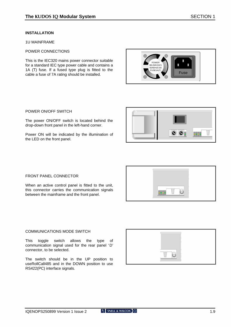
This is the IEC320 mains power connector suitablefor a standard IEC type power cable and contains a1A (T) fuse. If a fused type plug is fitted to thecable a fuse of 7A rating should be installed.
POWER ON/OFF SWITCH
The power ON/OFF switch is located behind thedrop-down front panel in the left-hand corner.
Power ON will be indicated by the illumination ofthe LED on the front panel.
FRONT PANEL CONNECTOR
When an active control panel is fitted to the unit,this connector carries the communication signalsbetween the mainframe and the front panel.
COMMUNICATIONS MODE SWITCH
This toggle switch allows the type ofcommunication signal used for the rear panel ‘D’connector, to be selected.
The switch should be in the UP position touseRollCall485 and in the DOWN position to useRS422(PC) interface signals.
Fuse
POWER88-264V(AC)50/60Hz0.6AFUSE1A(T)
The .8'26 ,4 Modular System SECTION 1
IQENOPS250899 Version 1 Issue 2 1.10
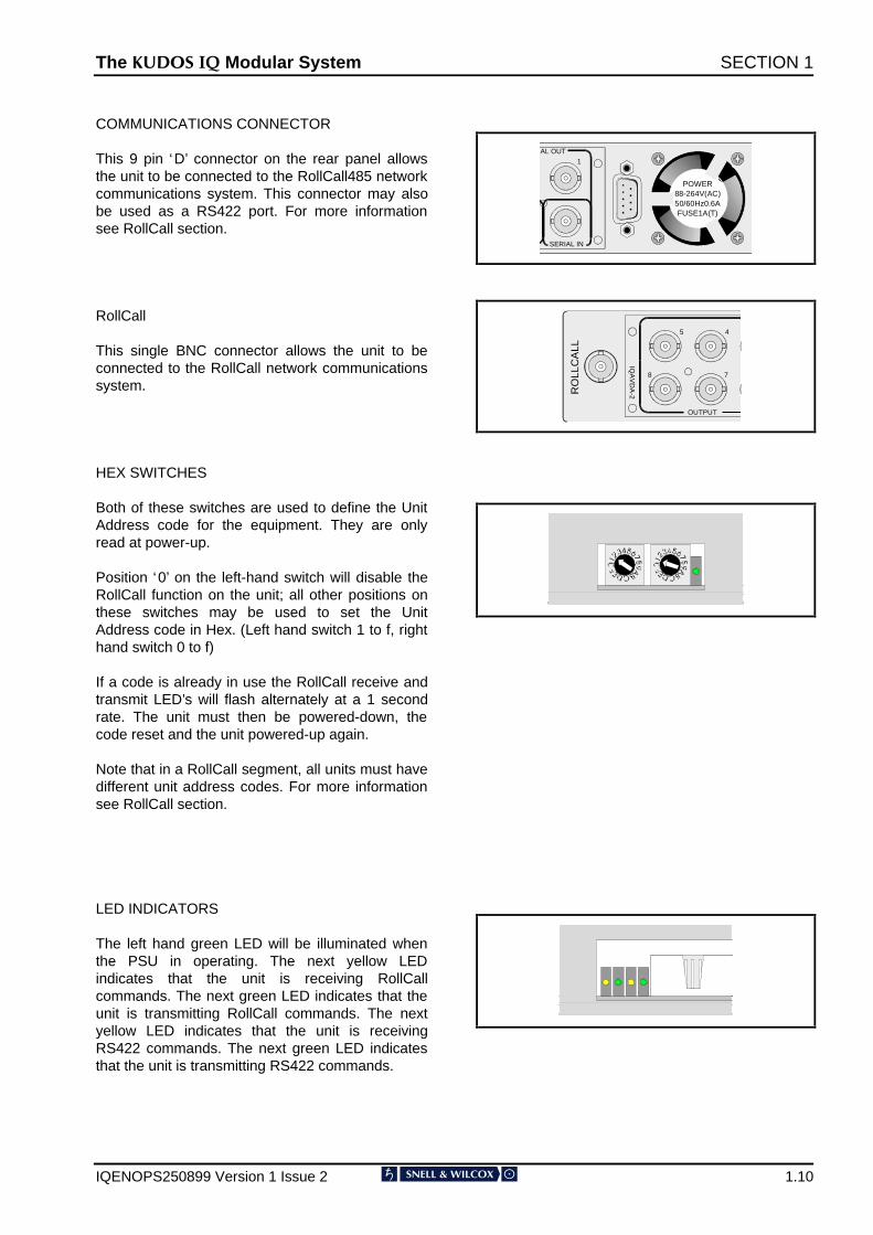
COMMUNICATIONS CONNECTOR
This 9 pin ‘D’ connector on the rear panel allowsthe unit to be connected to the RollCall485 networkcommunications system. This connector may alsobe used as a RS422 port. For more informationsee RollCall section.
RollCall
This single BNC connector allows the unit to beconnected to the RollCall network communicationssystem.
HEX SWITCHES
Both of these switches are used to define the UnitAddress code for the equipment. They are onlyread at power-up.
Position ‘0’ on the left-hand switch will disable theRollCall function on the unit; all other positions onthese switches may be used to set the UnitAddress code in Hex. (Left hand switch 1 to f, righthand switch 0 to f)
If a code is already in use the RollCall receive andtransmit LED’s will flash alternately at a 1 secondrate. The unit must then be powered-down, thecode reset and the unit powered-up again.
Note that in a RollCall segment, all units must havedifferent unit address codes. For more informationsee RollCall section.
LED INDICATORS
The left hand green LED will be illuminated whenthe PSU in operating. The next yellow LEDindicates that the unit is receiving RollCallcommands. The next green LED indicates that theunit is transmitting RollCall commands. The nextyellow LED indicates that the unit is receivingRS422 commands. The next green LED indicatesthat the unit is transmitting RS422 commands.
POWER88-264V(AC)50/60Hz0.6AFUSE1A(T)
SERIAL IN
IAL OUT
1
RO
LLC
ALL
OUTPUT
IQA
VD
A-2
45
78
The .8'26 ,4 Modular System SECTION 1
IQENOPS250899 Version 1 Issue 2 1.11
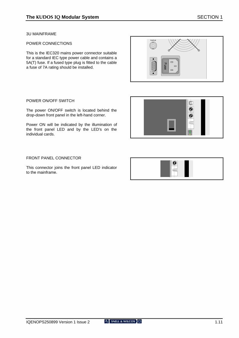
3U MAINFRAME
POWER CONNECTIONS
This is the IEC320 mains power connector suitablefor a standard IEC type power cable and contains a5A(T) fuse. If a fused type plug is fitted to the cablea fuse of 7A rating should be installed.
POWER ON/OFF SWITCH
The power ON/OFF switch is located behind thedrop-down front panel in the left-hand corner.
Power ON will be indicated by the illumination ofthe front panel LED and by the LED’s on theindividual cards.
FRONT PANEL CONNECTOR
This connector joins the front panel LED indicatorto the mainframe.
RollCall
The .8'26 ,4 Modular System SECTION 1
IQENOPS250899 Version 1 Issue 2 1.12
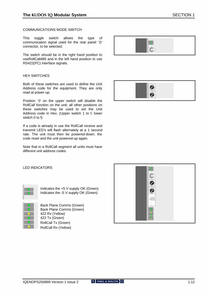
COMMUNICATIONS MODE SWITCH
This toggle switch allows the type ofcommunication signal used for the rear panel ‘D’connector, to be selected.
The switch should be in the right hand position touseRollCall485 and in the left hand position to useRS422(PC) interface signals.
HEX SWITCHES
Both of these switches are used to define the UnitAddress code for the equipment. They are onlyread at power-up.
Position ‘0’ on the upper switch will disable theRollCall function on the unit; all other positions onthese switches may be used to set the UnitAddress code in Hex. (Upper switch 1 to f, lowerswitch 0 to f)
If a code is already in use the RollCall receive andtransmit LED’s will flash alternately at a 1 secondrate. The unit must then be powered-down, thecode reset and the unit powered-up again.
Note that in a RollCall segment all units must havedifferent unit address codes.
LED INDICATORS
Indicates the +5 V supply OK (Green)Indicates the -5 V supply OK (Green)
Back Plane Comms (Green)Back Plane Comms (Green)422 Rx (Yellow)422 Tx (Green)RollCall Tx (Green)RollCall Rx (Yellow)
The .8'26 ,4 Modular System SECTION 1
IQENOPS250899 Version 1 Issue 2 1.13
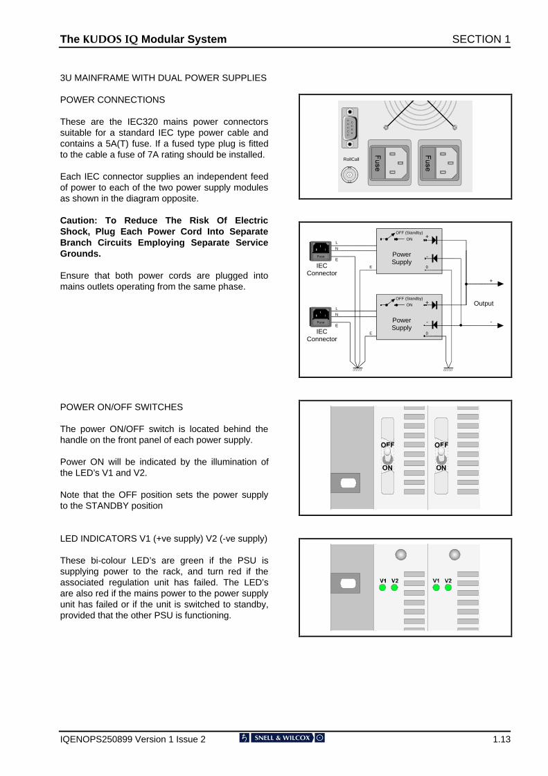
3U MAINFRAME WITH DUAL POWER SUPPLIES
POWER CONNECTIONS
These are the IEC320 mains power connectorssuitable for a standard IEC type power cable andcontains a 5A(T) fuse. If a fused type plug is fittedto the cable a fuse of 7A rating should be installed.
Each IEC connector supplies an independent feedof power to each of the two power supply modulesas shown in the diagram opposite.
Caution: To Reduce The Risk Of ElectricShock, Plug Each Power Cord Into SeparateBranch Circuits Employing Separate ServiceGrounds.
Ensure that both power cords are plugged intomains outlets operating from the same phase.
POWER ON/OFF SWITCHES
The power ON/OFF switch is located behind thehandle on the front panel of each power supply.
Power ON will be indicated by the illumination ofthe LED’s V1 and V2.
Note that the OFF position sets the power supplyto the STANDBY position
LED INDICATORS V1 (+ve supply) V2 (-ve supply)
These bi-colour LED’s are green if the PSU issupplying power to the rack, and turn red if theassociated regulation unit has failed. The LED’sare also red if the mains power to the power supplyunit has failed or if the unit is switched to standby,provided that the other PSU is functioning.
RollCall
PowerSupply
PowerSupply
Fuse
IECConnector
Fuse
IECConnector
L
N
E
LN
E
E
E
+
-
+
-
Output
OFF (Standby)
ON
OFF (Standby)
ON
0
0
+
-
The .8'26 ,4 Modular System SECTION 1
IQENOPS250899 Version 1 Issue 2 1.14
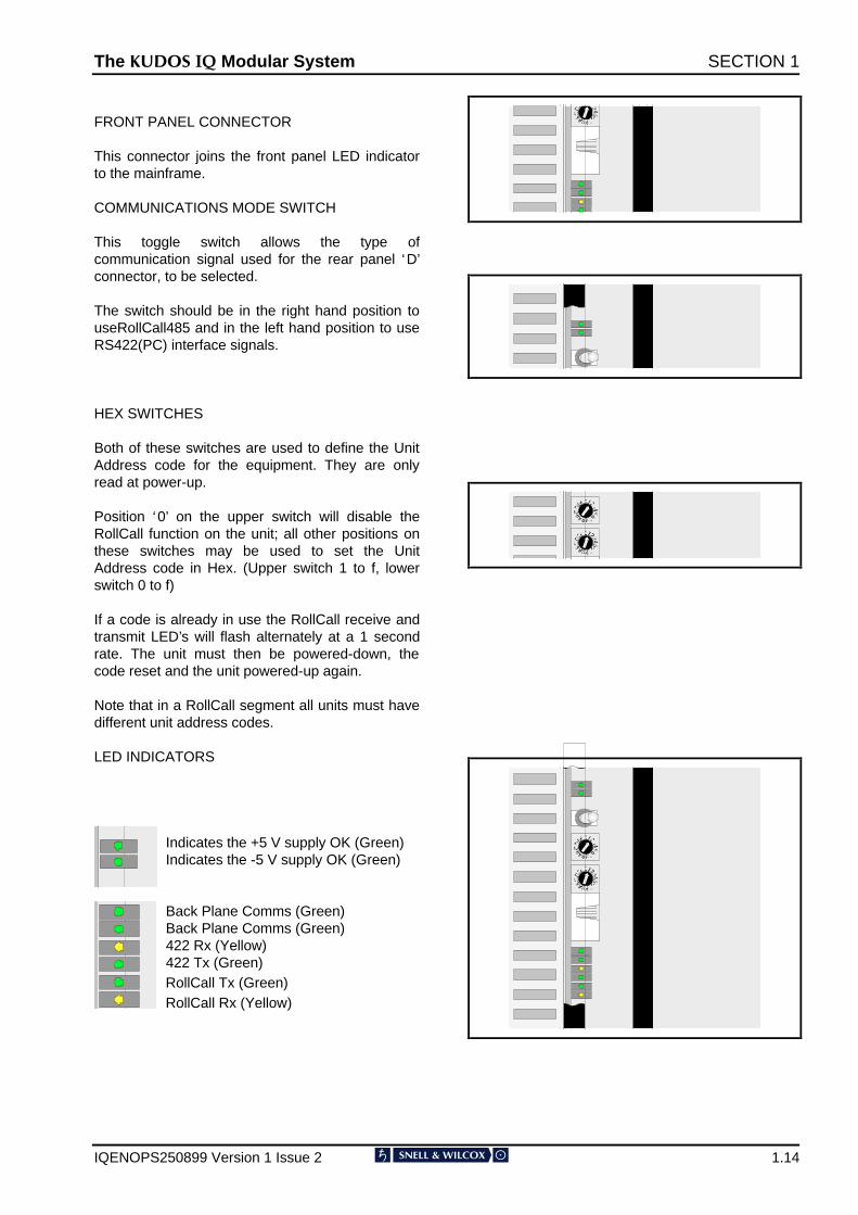
FRONT PANEL CONNECTOR
This connector joins the front panel LED indicatorto the mainframe.
COMMUNICATIONS MODE SWITCH
This toggle switch allows the type ofcommunication signal used for the rear panel ‘D’connector, to be selected.
The switch should be in the right hand position touseRollCall485 and in the left hand position to useRS422(PC) interface signals.
HEX SWITCHES
Both of these switches are used to define the UnitAddress code for the equipment. They are onlyread at power-up.
Position ‘0’ on the upper switch will disable theRollCall function on the unit; all other positions onthese switches may be used to set the UnitAddress code in Hex. (Upper switch 1 to f, lowerswitch 0 to f)
If a code is already in use the RollCall receive andtransmit LED’s will flash alternately at a 1 secondrate. The unit must then be powered-down, thecode reset and the unit powered-up again.
Note that in a RollCall segment all units must havedifferent unit address codes.
LED INDICATORS
Indicates the +5 V supply OK (Green)Indicates the -5 V supply OK (Green)
Back Plane Comms (Green)Back Plane Comms (Green)422 Rx (Yellow)422 Tx (Green)RollCall Tx (Green)RollCall Rx (Yellow)
The .8'26 ,4 Modular System SECTION 1
IQENOPS250899 Version 1 Issue 2 1.15
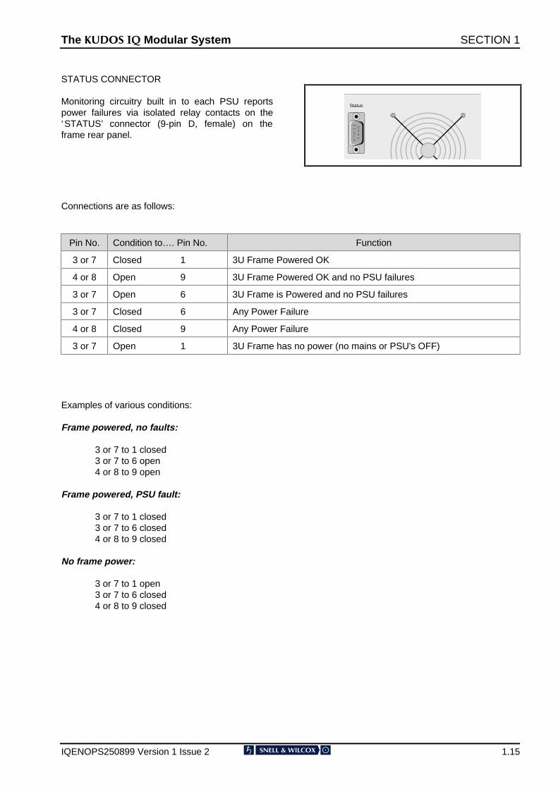
STATUS CONNECTOR
Monitoring circuitry built in to each PSU reportspower failures via isolated relay contacts on the‘STATUS’ connector (9-pin D, female) on theframe rear panel.
Status
Connections are as follows:
Pin No. Condition to…. Pin No. Function
3 or 7 Closed 1 3U Frame Powered OK
4 or 8 Open 9 3U Frame Powered OK and no PSU failures
3 or 7 Open 6 3U Frame is Powered and no PSU failures
3 or 7 Closed 6 Any Power Failure
4 or 8 Closed 9 Any Power Failure
3 or 7 Open 1 3U Frame has no power (no mains or PSU's OFF)
Examples of various conditions:
Frame powered, no faults:
3 or 7 to 1 closed 3 or 7 to 6 open 4 or 8 to 9 open
Frame powered, PSU fault:
3 or 7 to 1 closed 3 or 7 to 6 closed 4 or 8 to 9 closed
No frame power:
3 or 7 to 1 open3 or 7 to 6 closed4 or 8 to 9 closed
The .8'26 ,4 Modular System SECTION 1
IQENOPS250899 Version 1 Issue 2 1.16
Operation
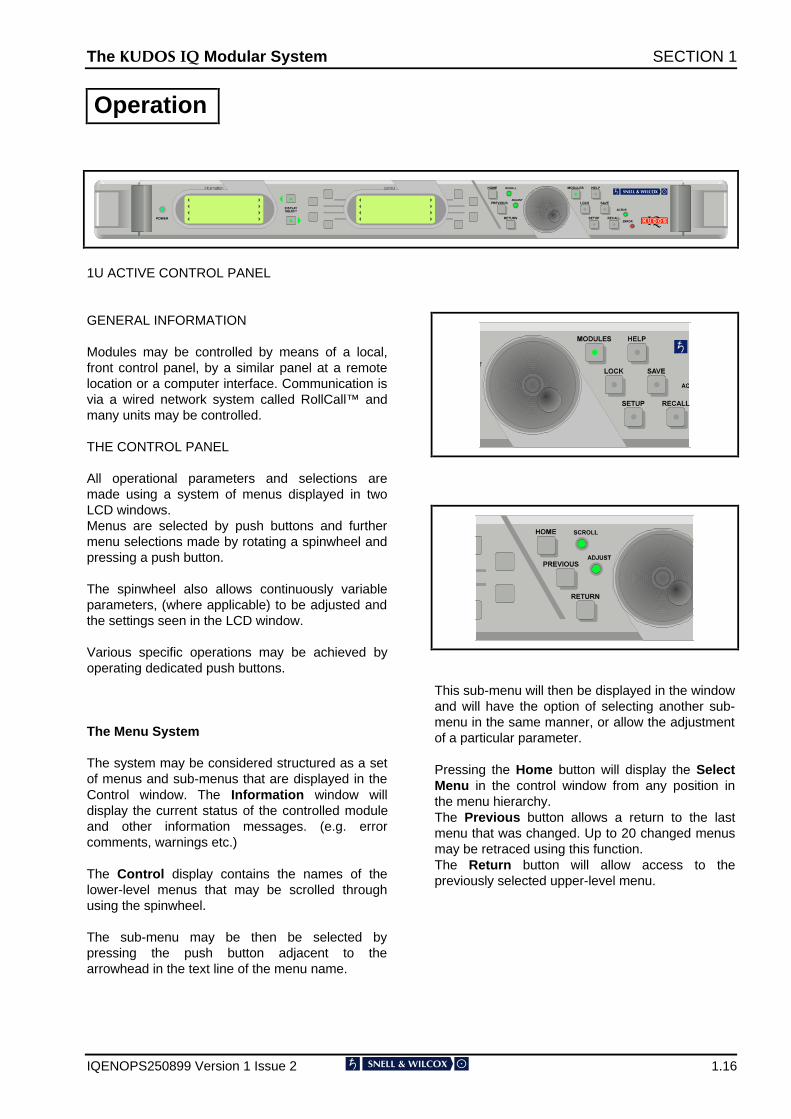
1U ACTIVE CONTROL PANEL
GENERAL INFORMATION
Modules may be controlled by means of a local,front control panel, by a similar panel at a remotelocation or a computer interface. Communication isvia a wired network system called RollCall™ andmany units may be controlled.
THE CONTROL PANEL
All operational parameters and selections aremade using a system of menus displayed in twoLCD windows.Menus are selected by push buttons and furthermenu selections made by rotating a spinwheel andpressing a push button.
The spinwheel also allows continuously variableparameters, (where applicable) to be adjusted andthe settings seen in the LCD window.
Various specific operations may be achieved byoperating dedicated push buttons.
The Menu System
The system may be considered structured as a setof menus and sub-menus that are displayed in theControl window. The Information window willdisplay the current status of the controlled moduleand other information messages. (e.g. errorcomments, warnings etc.)
The Control display contains the names of thelower-level menus that may be scrolled throughusing the spinwheel.
The sub-menu may be then be selected bypressing the push button adjacent to thearrowhead in the text line of the menu name.
This sub-menu will then be displayed in the windowand will have the option of selecting another sub-menu in the same manner, or allow the adjustmentof a particular parameter.
Pressing the Home button will display the SelectMenu in the control window from any position inthe menu hierarchy.The Previous button allows a return to the lastmenu that was changed. Up to 20 changed menusmay be retraced using this function.The Return button will allow access to thepreviously selected upper-level menu.
The .8'26 ,4 Modular System SECTION 1
IQENOPS250899 Version 1 Issue 2 1.17
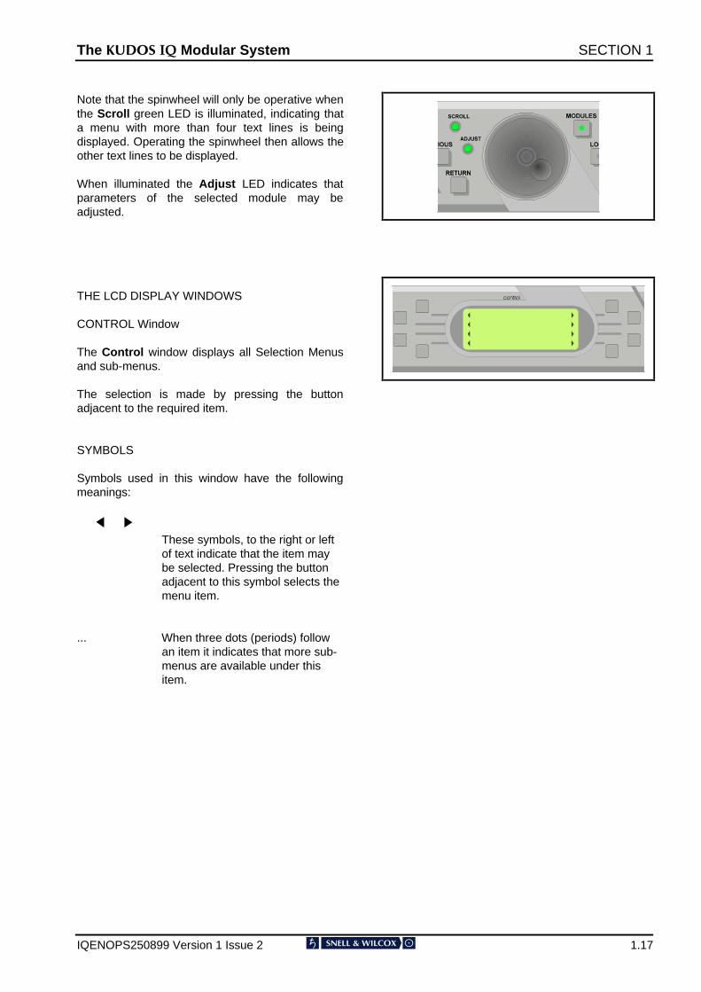
Note that the spinwheel will only be operative whenthe Scroll green LED is illuminated, indicating thata menu with more than four text lines is beingdisplayed. Operating the spinwheel then allows theother text lines to be displayed.
When illuminated the Adjust LED indicates thatparameters of the selected module may beadjusted.
THE LCD DISPLAY WINDOWS
CONTROL Window
The Control window displays all Selection Menusand sub-menus.
The selection is made by pressing the buttonadjacent to the required item.
SYMBOLS
Symbols used in this window have the followingmeanings:
These symbols, to the right or left of text indicate that the item may be selected. Pressing the button adjacent to this symbol selects the menu item.
... When three dots (periods) follow an item it indicates that more sub-menus are available under this item.
The .8'26 ,4 Modular System SECTION 1
IQENOPS250899 Version 1 Issue 2 1.18
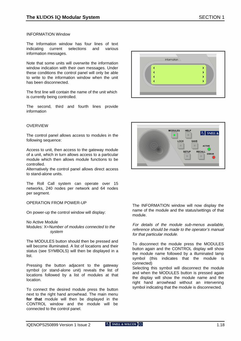
INFORMATION Window
The Information window has four lines of textindicating current selections and variousinformation messages.
Note that some units will overwrite the informationwindow indication with their own messages. Underthese conditions the control panel will only be ableto write to the information window when the unithas been disconnected.
The first line will contain the name of the unit whichis currently being controlled.
The second, third and fourth lines provideinformation
OVERVIEW
The control panel allows access to modules in thefollowing sequence:
Access to unit, then access to the gateway moduleof a unit, which in turn allows access to a particularmodule which then allows module functions to becontrolled.Alternatively the control panel allows direct accessto stand-alone units.
The Roll Call system can operate over 15networks, 240 nodes per network and 64 nodesper segment.
OPERATION FROM POWER-UP
On power-up the control window will display:
No Active ModuleModules: X=Number of modules connected to the
system
The MODULES button should then be pressed andwill become illuminated. A list of locations and theirstatus (see SYMBOLS) will then be displayed in alist.
Pressing the button adjacent to the gatewaysymbol (or stand-alone unit) reveals the list oflocations followed by a list of modules at thatlocation.
To connect the desired module press the buttonnext to the right hand arrowhead. The main menufor that module will then be displayed in theCONTROL window and the module will beconnected to the control panel.
The INFORMATION window will now display thename of the module and the status/settings of thatmodule.
For details of the module sub-menus available,reference should be made to the operator’s manualfor that particular module.
To disconnect the module press the MODULESbutton again and the CONTROL display will showthe module name followed by a illuminated lampsymbol (this indicates that the module isconnected)Selecting this symbol will disconnect the moduleand when the MODULES button is pressed againthe display will show the module name and theright hand arrowhead without an interveningsymbol indicating that the module is disconnected.
The .8'26 ,4 Modular System SECTION 1
IQENOPS250899 Version 1 Issue 2 1.19
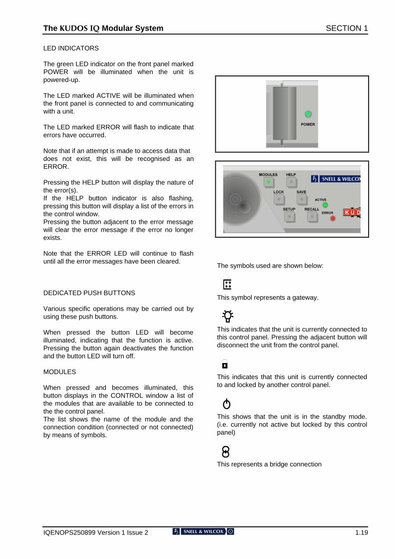
LED INDICATORS
The green LED indicator on the front panel markedPOWER will be illuminated when the unit ispowered-up.
The LED marked ACTIVE will be illuminated whenthe front panel is connected to and communicatingwith a unit.
The LED marked ERROR will flash to indicate thaterrors have occurred.
Note that if an attempt is made to access data thatdoes not exist, this will be recognised as anERROR.
Pressing the HELP button will display the nature ofthe error(s).If the HELP button indicator is also flashing,pressing this button will display a list of the errors inthe control window.Pressing the button adjacent to the error messagewill clear the error message if the error no longerexists.
Note that the ERROR LED will continue to flashuntil all the error messages have been cleared.
DEDICATED PUSH BUTTONS
Various specific operations may be carried out byusing these push buttons.
When pressed the button LED will becomeilluminated, indicating that the function is active.Pressing the button again deactivates the functionand the button LED will turn off.
MODULES
When pressed and becomes illuminated, thisbutton displays in the CONTROL window a list ofthe modules that are available to be connected tothe the control panel.The list shows the name of the module and theconnection condition (connected or not connected)by means of symbols.
The symbols used are shown below:
This symbol represents a gateway.
This indicates that the unit is currently connected tothis control panel. Pressing the adjacent button willdisconnect the unit from the control panel.
This indicates that this unit is currently connectedto and locked by another control panel.
This shows that the unit is in the standby mode.(i.e. currently not active but locked by this controlpanel)
This represents a bridge connection
The .8'26 ,4 Modular System SECTION 1
IQENOPS250899 Version 1 Issue 2 1.20
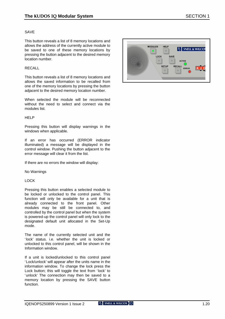
SAVE
This button reveals a list of 8 memory locations andallows the address of the currently active module tobe saved to one of these memory locations bypressing the button adjacent to the desired memorylocation number.
RECALL
This button reveals a list of 8 memory locations andallows the saved information to be recalled fromone of the memory locations by pressing the buttonadjacent to the desired memory location number.
When selected the module will be reconnectedwithout the need to select and connect via themodules list.
HELP
Pressing this button will display warnings in thewindows when applicable.
If an error has occurred (ERROR indicatorilluminated) a message will be displayed in thecontrol window. Pushing the button adjacent to theerror message will clear it from the list.
If there are no errors the window will display:
No Warnings
LOCK
Pressing this button enables a selected module tobe locked or unlocked to the control panel. Thisfunction will only be available for a unit that isalready connected to the front panel. Othermodules may be still be connected to, andcontrolled by the control panel but when the systemis powered-up the control panel will only lock to thedesignated default unit allocated in the Set-Upmode.
The name of the currently selected unit and the‘ lock’ status. i.e. whether the unit is locked orunlocked to this control panel, will be shown in theInformation window.
If a unit is locked/unlocked to this control panel‘Lock/unlock’ will appear after the units name in theinformation window. To change the lock press theLock button; this will toggle the text from ‘ lock’ to‘unlock’ The connection may then be saved to amemory location by pressing the SAVE buttonfunction.

The .8'26 ,4 Modular System SECTION 1
IQENOPS250899 Version 1 Issue 2 1.21
The DISPLAY SELECT buttons allow theInformation Window to display two different sets ofinformation:
1 Identity Codes
The first line will show the unit name
The second line will show the unit address codeand the RV (RollCall Version)
The third line will show the unit identity (RollCall)for that unit as three sets of digits separated by adot.
1st set = The version of the control unit2nd set = Variant of software version3rd set = Control compatibility version
number
The fourth line will display system save codes
2 Current selections and conditions
First Line: (Unit Name)
This line shows the name of the unit.. If the namehas been changed in the Unit Name Menu the newname will appear here.
Second line: Signal(s) input status
Third Line: Status of other signal
Fourth Line:
This line may be blank or show one of thefollowing:
Presetting
Presetting indicates that the unit has been asked toreturn all settings to their default values and theunit is performing this operation.

The .8'26 ,4 Modular System SECTION 1
IQENOPS250899 Version 1 Issue 2 1.22
The .8'26 ,4 Modular System SECTION 1
IQENOPS250899 Version 1 Issue 2 1.23
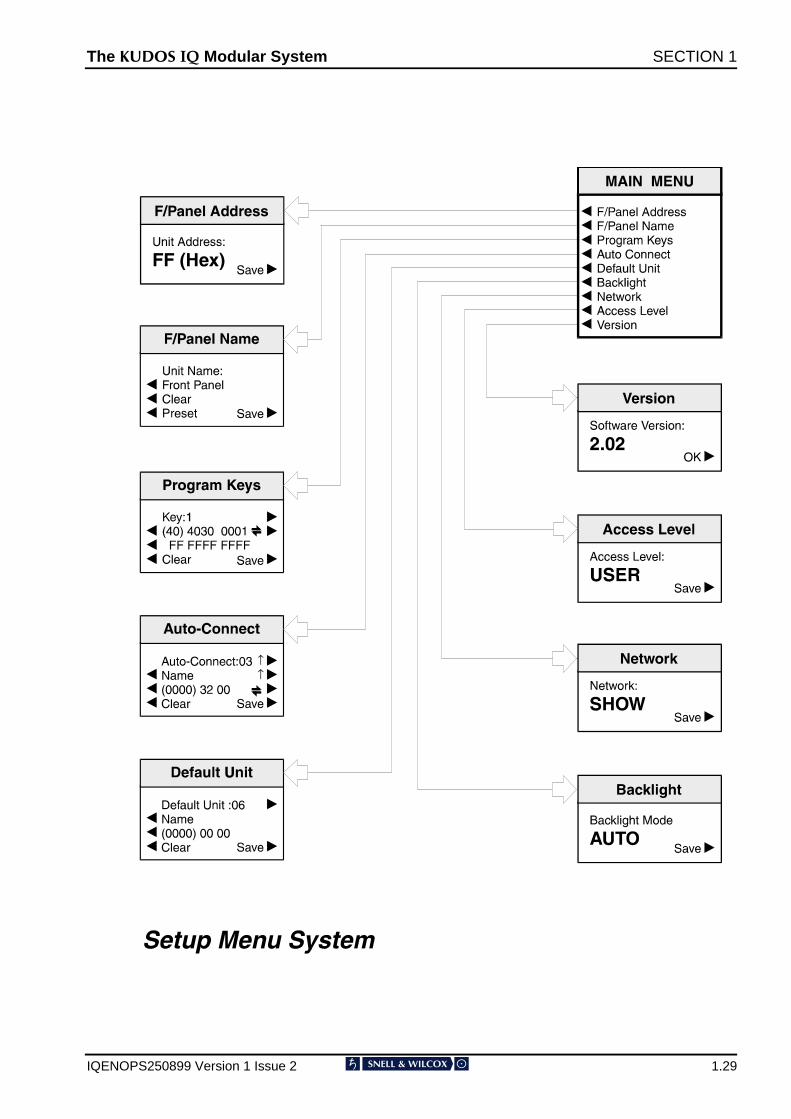
SETUP MENU SYSTEM
(For Software Version 6.1.8 onwards; for previousversion V6.0.7 see page 24, for versions previousto V6.0.7 see page 29)
Changes for Software Version 6.1.8
Lock Controls item added to main menu inSupervisor level with a sub-menu showing YES/NOdialogue box added.
Lock Controls
This item allows the front panel to be locked-outsuch that it is inoperative. This function can only beentered in the Supervisor access mode.
To set this function enter at Supervisor level, selectthe Lock Controls item to reveal the dialogue box.
Select either YES or NO and save.
The function is now set.
Note that if this function is set to
Lock Controls: YES
and the unit is powered-up, the message
Front Panel Locked by Supervisor!
will appear.
The .8'26 ,4 Modular System SECTION 1
IQENOPS250899 Version 1 Issue 2 1.24
The .8'26 ,4 Modular System SECTION 1
IQENOPS250899 Version 1 Issue 2 1.25
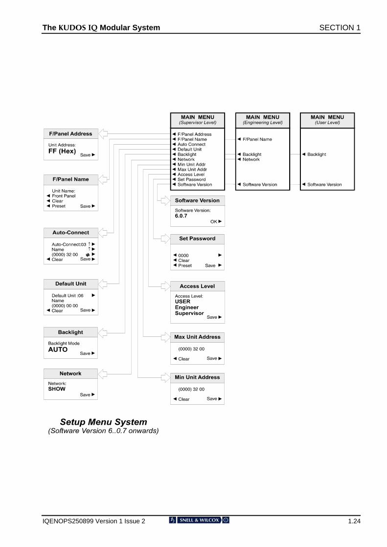
SETUP
(For Software Version 6.0.7; for previous versionssee page 29)
Pressing this button displays a list of front paneloptions in the CONTROL window. Examples ofthese are shown in the ‘Setup Menu System’drawing on the previous page.
Changes for Software Version 6.0.7
1. Program Keys function deleted from main menu
2. Items added to main menu:Min Unit AddrMax Unit AddrSet Password
3. Three levels of access are provided:User, Engineer and Supervisor, withpassword protection. Each access levelallows a particular set of sub-menus to beaccessed.
SETUP Sub-Menus
These are selected by pressing the button adjacentto the desired function.
Note that all these sub-menus include a SAVEfunction that is used to save particular settings. Ifthe changed settings do not need to be saved usethe RETURN function to return to the previousmenu; this action will abandon any changes andrevert to the previously saved settings.
F/Panel Address
The address of this control panel will be displayedas a 2-digit hexadecimal code.
Note that the code 0,0 effectively switches the unitoff from the network. The codes 0,1 to 0,F inclusiveare reserved for bridge addresses. Codes 1,0 toF,F inclusive are available to the user.
The address code is user defined in the range 1,0to F,F and is set by rotating the spinwheel to thedesired code and selecting the SAVE function.
The .8'26 ,4 Modular System SECTION 1
IQENOPS250899 Version 1 Issue 2 1.26
F/Panel Name
The control panel may be given a name using thisfunction (e.g. Edit Suite, Studio 2 etc.) Themaximum number of characters, including spaces,is 19 and may consist of letters and numbers(ASCII Characters)
To edit the name press either the left or right handbutton adjacent to the arrows for the centre textline until the character to be changed is flashing.(In the picture opposite this is the letter E) Usingthe spinwheel, scroll through to the characterrequired and then, using the left and right handbuttons, select the next character; the othercharacters may be changed in the same way.
When the name has been set to that requiredpress the SAVE function to save the name. Notethat to remove a character and leave a clear spacein the text line the Clear function (above Preset)should be used. The Preset function returns thetext to the original data.
Auto Connect
The Auto Connect menu allows a number of unitsto be automatically connected to the control panelat power-up.
Up to 16 units may be designated in this way byassigning a number to them. (00 to 15)
Note that these numbers are also used toassign the default unit .
The units in this list are (on power-up) in thestandby mode and although not currently active arelocked to this control panel and may not becontrolled by any other panel.
The unit name (second text line of the controlwindow display) may be displayed by scrollingthrough the list using the button adjacent to the ìarrow.
The network address of the unit is shown in thethird text line as three sets of hexadecimal codes.
The first set is the network address, the second setis the physical unit address and the third set is theport address. Each set of these codes may beselected (the set will be shown enclosed inbrackets) by pressing the button adjacent to thisline.
The code may then be changed using thespinwheel.
The code may be reset to 0000 00 00 by pressingthe clear button. This action also removes the unitname from the display and inserts a ? symbolindicating that no unit will be connected to thissession.
The Auto Connect set-up may be saved bypressing either the dedicated front panel Savebutton or by pressing the button adjacent to theSave display text.
The .8'26 ,4 Modular System SECTION 1
IQENOPS250899 Version 1 Issue 2 1.27
Default Unit
On power-up the default unit will be automaticallyconnected, its menus retrieved and will be readyfor active control.
To define the default unit select Default Unit. Pressthe button adjacent to the default text arrowheaduntil the desired number is reached. (This numberis the number assigned to a particular unit in theAuto Connect set-up) The name of this unit willappear in the second line of text.
Select Save to save this setting.
The Clear selection sets the default unit to ‘None’
Note that if no units have been assigned numbersin the Auto Connect set-up a ? will appear in thesecond line of text. Also when the numbers areselected (in rotation) the word ‘None’ will appearafter Default Unit when the number 15 isexceeded. This confirms that no units have beenassigned a number.
Note that only one unit may be designated as thedefault unit.
BackLight
Selecting this function allows the backlighting of thedisplay windows to set, by rotating the spinwheel,to the following modes:
OFF
Backlight always Off. Use this mode where ambientlight level is high.
ON
Backlight always On. Use this mode where ambientlight level is low to improve text visibility.
AUTO
Backlight will normally be On but will default to Offafter 2 minutes. The backlight will return to Auto Onwhenever any front panel control is operated.
Press the button adjacent to the Save text to savethe backlight mode.
Network
This function allows the front panel to be ‘hidden’from the network system. In the Hide mode thisfront panel will not appear in the Module Listdisplayed on other control panels in the system.
SHOW
This front panel will appear in the Module List ofother control panels.
HIDE
This front panel will not appear in the Module Listof other control panels.
Min/Max Unit Addr
The front panel can only hold a maximum of 200addresses. The Min and Max Unit Addr (Address)function allows a range of addresses to beconfigured for partial use of the network.
The Min Unit Addr selection sets the minimumaddress.
The Max Unit Addr selection sets the maximumaddress.
The overall range of addresses is from 1 to 255.
The .8'26 ,4 Modular System SECTION 1
IQENOPS250899 Version 1 Issue 2 1.28
Access Level
The setup of the active front panel may beaccessed at various levels. At the highest level(Supervisor) access is allowed to all functions. Thislevel may only be accessed by entering apassword. At lower levels (User and Engineer)access is only allowed to a limited number offunctions.
As supplied the unit will be in a temporarySupervisor mode with no password protectedaccess levels.
From the main menu select Set Password
To enter the Supervisor level and set up apassword proceed as follows:
1. Power-down the unit
2. Hold down the Modules button and power-upthe unit. Continue to hold down the button for afew seconds while powering-up.
3. From the main menu select Access Level
4. Using the spinwheel, select Supervisor andpress Save
5. From the main menu select Set Password
6. The default password will be 0000 To changethe password select the line for digits 1, 2, 3and 4, and using the spinwheel to select thedesired characters. Press Save
The password has now been set.
Selection levels are:
USER Provides access to basic usercontrols.
ENGINEER Provides access to more controlsthan at user level but less than atsupervisor level.
SUPERVISOR Provides access to all availablecontrol functions.
To set up this function rotate the spinwheel to thedesired level and select Save.
Note that the number of control functions availableat the various levels are set by thesoftware/hardware of the module and are not user-adjustable.
Version
This shows the Software version number. PressOK to return to the previous menu.
SAVE
This button reveals a list of 8 memory locations andallows the address of the currently active module tobe saved to one of these memory locations bypressing the button adjacent to the desired memorylocation number.
RECALL
This button reveals a list of 8 memory locations andallows the saved information to be recalled fromone of the memory locations by pressing the buttonadjacent to the desired memory location number.
When selected the module will be reconnectedwithout the need to select and connect via themodules list.
HELP
Pressing this button will display warnings in thewindows when applicable.
If an error has occurred (ERROR indicatorilluminated) a message will be displayed in thecontrol window. Pushing the button adjacent to theerror message will clear it from the list.
If there are no errors the window will display:
No Warnings
The .8'26 ,4 Modular System SECTION 1
IQENOPS250899 Version 1 Issue 2 1.29

The .8'26 ,4 Modular System SECTION 1
IQENOPS250899 Version 1 Issue 2 1.30
SETUP(For Software previous to Version 6.0.7; for laterversion V6.0.7 see page 24, for V6.1.8 see page22)
Pressing this button displays a list of front paneloptions in the CONTROL window. Examples ofthese are shown in the ‘Setup Menu System’drawing.
SETUP Sub-Menus
These are selected by pressing the button adjacentto the desired function.
Note that all these sub-menus include a SAVEfunction which is used to save particular settings. Ifthe changed settings do not need to be saved usethe RETURN function to return to the previousmenu; this action will abandon any changes andrevert to the previously saved settings.
F/Panel Address
The address of this control panel will be displayedas a 2-digit hexadecimal code.Note that the code 0,0 effectively switches the unitoff from the network. The codes 0,1 to 0,F inclusiveare reserved for bridge addresses. Codes 1,0 toF,F inclusive are available to the user.
The address code is user defined in the range 1,0to F,F and is set by rotating the spinwheel to thedesired code and selecting the SAVE function.
F/Panel Name
The control panel may be given a name using thisfunction (e.g. Edit Suite, Studio 2 etc.)The maximum number of characters, includingspaces, is 19 and may consist of letters andnumbers (ASCII Characters)
To edit the name press either the left or right handbutton adjacent to the arrows for the centre textline until the character to be changed is flashing.
Using the spinwheel, scroll through to the characterrequired and then, using the left and right handbuttons, select the next character; the othercharacters may be changed in the same way.
When the name has been set to that requiredpress the SAVE function to save the name.
Note that to remove a character and leave a clearspace in the text line the Clear function (abovePreset) should be used.
The Preset function returns the text to the originaldata.
Program Keys
This function is not available to the user.
Auto Connect
The Auto Connect menu allows a number of unitsto be automatically connected to the control panelat power-up.
Up to 16 units may be designated in this way byassigning a number to them. (00 to 15)
Note that these numbers are also used toassign the default unit.
The units in this list are (on power-up) in thestandby mode and although not currently active arelocked to this control panel and may not becontrolled by any other panel.
The unit name (second text line of the controlwindow display) may be displayed by scrollingthrough the list using the button adjacent to thearrow.
The network address of the unit is shown in thethird text line as three sets of hexadecimal codes.
The first set is the network address, the second setis the physical unit address and the third set is theport address. Each set of these codes may beselected (the set will be shown enclosed inbrackets) by pressing the button adjacent to thisline.
The code may then be changed using thespinwheel.
The code may be reset to 0000 00 00 by pressingthe clear button. This action also removes the unitname from the display and inserts a ? symbolindicating that no unit will be connected to thissession.
The Auto Connect set-up may be saved bypressing either the dedicated front panel Savebutton or by pressing the button adjacent to theSave display text.
The .8'26 ,4 Modular System SECTION 1
IQENOPS250899 Version 1 Issue 2 1.31
Default Unit
On power-up the default unit will be automaticallyconnected, its menus retrieved and will be readyfor active control.
To define the default unit select Default Unit. Pressthe button adjacent to the default text arrowheaduntil the desired number is reached. (This numberis the number assigned to a particular unit in theAuto Connect set-up) The name of this unit willappear in the second line of text.
Select Save to save this setting.
The Clear selection sets the default unit to ‘None’
Note that if no units have been assigned numbersin the Auto Connect set-up a ? will appear in thesecond line of text. Also when the numbers areselected (in rotation) the word ‘None’ will appearafter Default Unit when the number 15 isexceeded. This confirms that no units have beenassigned a number.
Note that only one unit may be designated as thedefault unit.
BackLight
Selecting this function allows the backlighting of thedisplay windows to set, by rotating the spinwheel,to the following modes:
OFF
Backlight always Off. Use this mode where ambientlight level is high.
ON
Backlight always On. Use this mode where ambientlight level is low to improve text visibility.
AUTO
Backlight will normally be On but will default to Offafter 2 minutes.The backlight will return to Auto On whenever anyfront panel control is operated.
Press the button adjacent to the Save text to savethe backlight mode.
The .8'26 ,4 Modular System SECTION 1
IQENOPS250899 Version 1 Issue 2 1.32
Network
This function allows the front panel to be ‘hidden’from the network system. In the Hide mode thisfront panel will not appear in the Module Listdisplayed on other control panels in the system.
SHOW This front panel will appear in theModule List of other control panels.
HIDE This front panel will not appear inthe Module List of other controlpanels.
Access Level
The number of module functions and parametersthat may be accessed and controlled by the frontpanel is set by the Access Level menu.Some modules have a large number of variableswhich, under normal conditions, the user will notneed to control whereas an engineer or supervisorwill need to be able to control an increasingnumber of parameters.
Selection levels are:
USER Provides access to basic user controls.
ENGINEER Provides access to more controls than at user level but less than at supervisor level.
SUPERVISOR Provides access to all available control functions.
To set up this function, rotate the spinwheel to thedesired level and select Save.
Note that the number of control functions availableat the various levels are set by thesoftware/hardware of the module and are not user-adjustable.
Version
This shows the Software version number. PressOK to return to the previous menu.
SAVE
This button reveals a list of 8 memory locations andallows the address of the currently active module tobe saved to one of these memory locations bypressing the button adjacent to the desired memorylocation number.RECALL
This button reveals a list of 8 memory locations andallows the saved information to be recalled fromone of the memory locations by pressing the buttonadjacent to the desired memory location number.
When selected the module will be reconnectedwithout the need to select and connect via themodules list.
HELP
Pressing this button will display warnings in thewindows when applicable.
If an error has occurred (ERROR indicatorilluminated) a message will be displayed in thecontrol window. Pushing the button adjacent to theerror message will clear it from the list.
If there are no errors the window will display:
No Warnings
The .8'26 ,4 Modular System SECTION 1
IQENOPS250899 Version 1 Issue 2 1.33
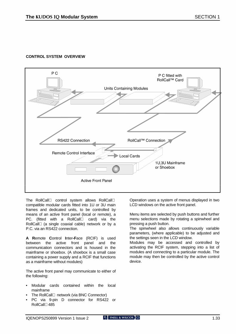
CONTROL SYSTEM OVERVIEW
The RollCall control system allows RollCallcompatible modular cards fitted into 1U or 3U mainframes and dedicated units, to be controlled bymeans of an active front panel (local or remote), aPC. (fitted with a RollCall card) via theRollCall (a single coaxial cable) network or by aP.C. via an RS422 connection.
A Remote Control Inter-Face (RCIF) is usedbetween the active front panel and thecommunication connectors and is housed in themainframe or shoebox. (A shoebox is a small casecontaining a power supply and a RCIF that functionsas a mainframe without modules)
The active front panel may communicate to either ofthe following:
• Modular cards contained within the localmainframe
• The RollCall network (via BNC Connector)• PC via 9-pin D connector for RS422 or
RollCall485
Operation uses a system of menus displayed in twoLCD windows on the active front panel.
Menu items are selected by push buttons and furthermenu selections made by rotating a spinwheel andpressing a push button.The spinwheel also allows continuously variableparameters, (where applicable) to be adjusted andthe settings seen in the LCD window.Modules may be accessed and controlled byactivating the RCIF system, stepping into a list ofmodules and connecting to a particular module. Themodule may then be controlled by the active controldevice.
The .8'26 ,4 Modular System SECTION 1
IQENOPS250899 Version 1 Issue 2 1.34
The .8'26 ,4 Modular System SECTION 1
IQENOPS250899 Version 1 Issue 2 1.35
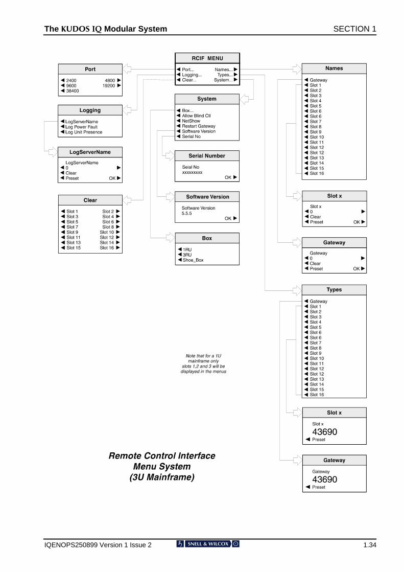
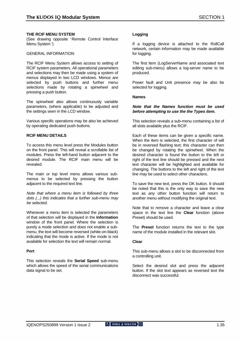
THE RCIF MENU SYSTEM(See drawing opposite ‘Remote Control InterfaceMenu System ’)
GENERAL INFORMATION
The RCIF Menu System allows access to setting ofRCIF system parameters. All operational parametersand selections may then be made using a system ofmenus displayed in two LCD windows. Menus areselected by push buttons and further menuselections made by rotating a spinwheel andpressing a push button.
The spinwheel also allows continuously variableparameters, (where applicable) to be adjusted andthe settings seen in the LCD window.
Various specific operations may be also be achievedby operating dedicated push buttons.
RCIF MENU DETAILS
To access this menu level press the Modules buttonon the front panel. This will reveal a scrollable list ofmodules. Press the left-hand button adjacent to thedesired module. The RCIF main menu will berevealed.
The main or top level menu allows various sub-menus to be selected by pressing the buttonadjacent to the required text line.
Note that where a menu item is followed by threedots (...) this indicates that a further sub-menu maybe selected.
Whenever a menu item is selected the parametersof that selection will be displayed in the Informationwindow of the front panel. Where the selection ispurely a mode selection and does not enable a sub-menu, the text will become reversed (white-on-black)indicating that the mode is active. If the mode is notavailable for selection the text will remain normal.
Port
This selection reveals the Serial Speed sub-menuwhich allows the speed of the serial communicationsdata signal to be set.
Logging
If a logging device is attached to the RollCallnetwork, certain information may be made availablefor logging.
The first item (LogServerName and associated textediting sub-menu) allows a log-server name to beproduced.
Power fault and Unit presence may be also beselected for logging.
Names
Note that the Names function must be usedbefore attempting to use the the Types item.
This selection reveals a sub-menu containing a list ofall slots available plus the RCIF.
Each of these items can be given a specific name.When the item is selected, the first character of willbe in reversed flashing text; this character can thenbe changed by rotating the spinwheel. When thedesired character is found the button to the left orright of the text line should be pressed and the nexttext character will be highlighted and available forchanging. The buttons to the left and right of the textline may be used to select other characters.
To save the new text, press the OK button. It shouldbe noted that this is the only way to save the newtext as any other button function will return toanother menu without modifying the original text.
Note that to remove a character and leave a clearspace in the text line the Clear function (abovePreset) should be used.
The Preset function returns the text to the typename of the module installed in the relevant slot.
Clear
This sub-menu allows a slot to be disconnected froma controlling unit.
Select the desired slot and press the adjacentbutton. If the slot text appears as reversed text thedisconnect was successful.

The .8'26 ,4 Modular System SECTION 1
IQENOPS250899 Version 1 Issue 2 1.36
Types
Note that the Names item must be used beforeattempting to use this item.
This selection reveals a sub-menu containing a listof all slots available plus the RCIF.
The Names function allows a slot to be given auseful name e.g. DECODER A and so long as thecorrect card stays in that slot there will be noproblems. However, if the card is replaced with anincorrect type e.g. an Encoder, the card will stillappear to be DECODER A, which would beincorrect.
The Types function allows the unique RollCallidentification number, in this example for thedecoder, to be allocated to the slot. If an incorrectcard type is installed in the slot the RollCall ID willnot be correct and the actual card type e.g. theencoder card, will be displayed in the window.
This function also has the advantage that namesand types may be setup before delivery that greatlyeases on-site installation and de-bugging.
System
Box
This item reveals a sub-menu that allows the typeof box (enclosure) to be selected. Either a 1RU,3RU or Shoe Box types may be selected.
Allow Blind Control
Blind Control is the ability to control a unit without aconnection. Active Front Panels and RollCall PCprograms use a RollCall connection to control amodule. RollTrack (used for setting, for example,audio delay times to track video delays) does notuse a connection, but just sets the delay. If achassis fitted with modules which will be controlledby Blind Control (RollTrack and some third partyremote control systems) then Allow Blind Controlmust be enabled. If Blind Control is not be usedthen Allow Blind Control may be disabled, givingprotection against incorrectly set-up RollTracksource modules.
NetShow
This function allows a unit to be ‘hidden’ from thenetwork system. Pressing the adjacent button willtoggle the text from normal to reversed.
When the text shows as normal the previouslyselected unit will not appear in the Module Listdisplayed on other control panels in the system.
When the text is reversed the unit will appear in theModule List displayed on other control panels in thesystem.
Note that if a unit is ‘hidden’ and control is requiredthe unit’s address should be changed using theHex switches on the Remote Control Interfacecard When the unit address is changed and theunit powed-down and powered-up the NetShowstate will be found to be in reversed text and theunit will now be shown in the Module List.
Also your connection to this unit will be lost within60 seconds.
Restart Gateway
Selecting this function will re-boot the Gatewaysystem with any changes incorporated. Thisprovides an easier alternative to a power-downpower-up operation.
Software_Version
This reveals the version number of the softwareused in the RCIF. Press OK to return to theprevious menu.