Embed Size (px)
Citation preview
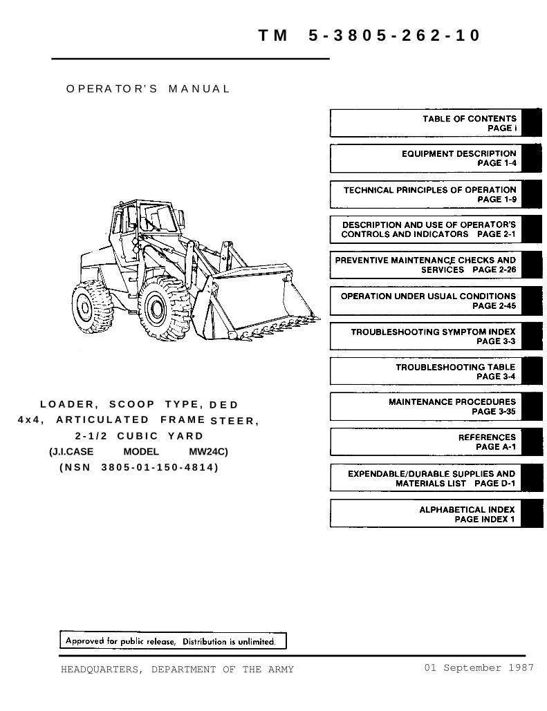
T M 5 - 3 8 0 5 - 2 6 2 - 1 0
O P E R A T O R ’ S M A N U A L
L O A D E R , S C O O P T Y P E ,
4 x 4 , A R T I C U L A T E D F R A M E
2 - 1 / 2 C U B I C Y A R D
D E D
S T E E R ,
(J.I.CASE MODEL MW24C)
( N S N 3 8 0 5 - 0 1 - 1 5 0 - 4 8 1 4 )
HEADQUARTERS, DEPARTMENT OF THE ARMY 01 September 1987


WARNING
WARNING
WARNING
WARNING
TOXIC/FLAMMABLE
Dry cleaning solvent P-D-680 used to clean parts is toxic and flammable. Wearprotective goggles and gloves and use only in a well ventilated area. Avoid contactwith skin, eyes and clothes and don’t breathe vapors. Do not use near open flame orexcessive heat and don’t smoke when using it. Failure to do so could cause seriousinjury. If you become dizzy while using cleaning solvent, get fresh air and medicalattention immediately. If contact with skin or clothes is made, flush with largeamounts of water. If contact with eyes is made, wash eyes with water and get medicalaid immediately.
Starting fluid is toxic and highly flammable. Container is pressurized to act as anexpellent. Don’t heat container and don-t discharge starting fluid in confined areasor near open flame. Don’t discard used container in an open flame. To do any of theabove will cause an explosion. Don’t breathe ether vapor or allow ether to come incontact with your skin. To do so will cause severe injury or death.
HIGH VELOCITY AIR
Compressed air used for cleaning purpose will not exceed 30 psi. Use only witheffective chip guarding and personal protectiveetc). Failure to do so could cause serious injuryyou hurt your eyes or if a foreign object isattention immediately.
equipment (goggles/shield, gloves,to eyes and possible blindness. Ifblown into your eyes, seek medical
FALLING EQUIPMENT
Be careful when inspecting blade cutting edges not to place any part of your bodybetween clamshell and blade. To do so could cause serious injury if clamshellsuddenly closes crushing you.
When using chain hoist to remove or install parts, be sure chain hoist is securelyfastened to the part and that all slack in chain is taken up. Failure to do so couldcause serious injury due to the part falling on you. If you are injured by fallingequipment, obtain medical aid immediately.
TOWING THE LOADER
Don’t allow personnel in or near the loader when it is being towed with the enginestopped. To do so could cause serious injury or death.
a
TM 5-3805-262-10
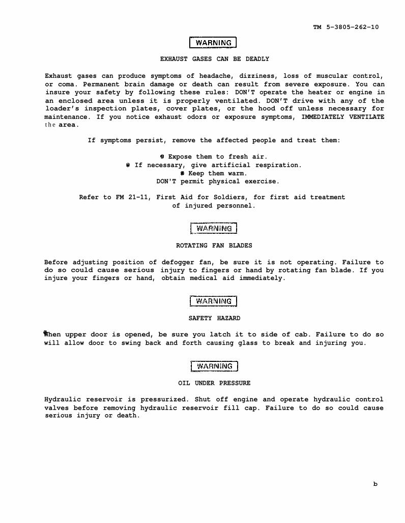
EXHAUST GASES CAN BE DEADLY
Exhaust gases can produce symptoms of headache, dizziness, loss of muscular control,or coma. Permanent brain damage or death can result from severe exposure. You caninsure your safety by following these rules: DON’T operate the heater or engine inan enclosed area unless it is properly ventilated. DON’T drive with any of theloader’s inspection plates, cover plates, or the hood off unless necessary formaintenance. If you notice exhaust odors or exposure symptoms, IMMEDIATELY VENTILATEthe area.
If symptoms persist, remove the affected people and treat them:
@ Expose them to fresh air.@ If necessary, give artificial respiration.
@ Keep them warm.@ DON'T permit physical exercise.
Refer to FM 21-11, First Aid for Soldiers, for first aid treatment
Before adjusting position ofdo so could cause seriousinjure your fingers or hand,
of injured personnel.
ROTATING FAN BLADES
defogger fan, be sure it is not operating. Failure toinjury to fingers or hand by rotating fan blade. If youobtain medical aid immediately.
SAFETY HAZARD
When upper door is opened, be sure you latch it to side of cab. Failure to do sowill allow door to swing back and forth causing glass to break and injuring you.
OIL UNDER PRESSURE
Hydraulic reservoir is pressurized. Shut off engine and operate hydraulic controlvalves before removing hydraulic reservoir fill cap. Failure to do so could causeserious injury or death.
b

TM 5-3805-262-10
NOISE HAZARD
Noise level exceeds 85 dB when operating loader with cab windows open. All personnelshall wear a hearing protective device when operating loader with windows open toprevent hearing loss.
EXPLOSIVE HAZARD
Don’t use jumper cables connected to battery terminals to start engine or chargebatteries. Always use slave receptacle. Failure to do so could cause serious injurydue to batteries exploding caused by improper connection of jumper cables to batteryterminals.
STEAM UNDER PRESSURE
Remove radiatorengine is hot.you. If you are
Before starting
cap slowly to relieve pressure before completely removing whenFailure to do so could cause severe burns due to hot steam scaldingscalded by hot steam, seek medical aid immediately.
engine, check and be sure that transport/service link is in releasedposition. Failure to do so will cause loss of steering control which may result inserious injury or death and extensive property damage.
Always use hand rails and stepssteering wheel or controls as
when you mount or dismount loader. Don’t usea hand rail. Any other method of mounting or
dismounting loader could make you slip and fall causing serious injury to yourself.
Before starting engine, fasten your seat belt secureley and be sure parking brake isapplied, transmission control lever is in neutral (N) position, and both cab doorsare closed. Failure to do so could cause serious injury or death due to an accident.
Operating on a hillside can be dangerous. Rain, snow, loose gravel, soft groundsetc., change ground conditions. Only you, the operator, can determine if yourmachine can be safely operated on any hillside or ramp. c

TM 5-3805-262-10
Before you operate on any hillside or ramp, always select low range and never coastdown hill with transmission in neutral (N). To do so could cause you to lose controlof loader and roll over causing loss of life or serious injury and extensiveproperty damage.
Keep loader bucket as low as possible. This low position gives better balance andpermits you to see ground condition more clearly. If bucket is full and you moveloader over rough terrain or terrain that can cause loader to slide, always operateloader at slow speed. Failure to do so could cause you to lose control over loadercausing serious injury or loss of life and extensive property damage.
Before moving loader up ramps, remove all ice, oil or grease from ramp to preventloader from falling and causing death or serious injury and extensive damage toloader. Tell personnel to move away from loader.
Don’t allow personnel in or near the loader when it is being towed with the enginestopped. To do so could cause serious injury or death.
Diesel fuel is highly combustible. Do not smoke or allow open flames or sparks intothe area. Death or severe injury may result if personnel fail to observe thisprecaution. If you are burned , obtain medical aid immediately.
Before performing any loader maintenance that requires servicing in area betweenfront and rear chassis, be sure that transport/service link is engaged. Failure todo so could cause serious injury or death due to chassis pivoting and crushing youwhen you are working in area between front and rear chassis.
Don’t depress button in center of steering wheel while operating loader. Button isnot a horn button. Depressing this button causes steering wheel to collapse forshipment purposes. If you depress this button while operating loader, steering wheelwill collapse. Your fingers could be crushed between steering wheel and windshieldwiper motor bracket causing painful injury to fingers. d

TM 5-3805-262-10
MW24C Loader
e/f blank


TM 5-3805-262-10
HEADQUARTERS Change DEPARTMENT OF THE ARMY
Washington, D.C., 19 December 2008
OPERATOR’S MANUAL
FOR
LOADER, SCOOP TYPE, DED,4 x 4, ARTICULATED FRAME STEER,
2-1/2 CUBIC YARD(J.I. CASE MODEL MW24C)
(NSN 3805-01-150-4814)
TM 5-3805-262-10, 01 September 1987, is changed as follows:
1. Remove old pages and insert new pages. 2. New or changed material is indicated by a vertical bar in the margin of the page.
Remove Pages Insert Pages
i/ii1-15 and 1-16 1-15 and 1-16
DA Form 2028 Sample DA Form 2028 SampleDA Form 2028 (3 copies) DA Form 2028 (3 copies)
3. File this change sheet in front of the publication for reference purpose.
C02
TECHNICAL MANUAL
DISTRIBUTION STATEMENT A: Approved for public release; distribution is unlimited.
No. 2
A/(B blank) i/ii
TM 5-3805-262-10 C02
By Order of the Secretary of the Army:
GEORGE W. CASEY, JR. General, United States Army
Chief of Staff
Official:
JOYCE E. MORROW Administrative Assistant to the
Secretary of the Army
0833006
DISTRIBUTION: To be distributed in accordance with the initial distribution number (IDN) 252302, requirements for TM 5-3805-262-10.
TM 5-3805-262-10
C 1
C H A N G E
No. 1
OPERATOR’S MANUAL
LOADER, SCOOP TYPE, DED,
TM
1.
2.TA
3.
HEADQUARTERSDEPARTMENT OF THE ARMYWashington, D.C., 02 August 1990
4 x 4 ,ARTICULATED FRAME STEER,
2-1/2 CUBIC YARD(J.I. CASE MODEL MW24C)
(NSN 3805-01-150-4814)
5-3805-262-10, 01 September 1987, is changed as follows:
Remove old pages and insert new pages as indicated below.
New or changed material is indicated by a vertical bar in the margin and by a vertical bar adjacent to thenumber.
Remove Pages Insert Pages
i and ii I and ii
2-33 and 2-34 2-33 and 2-34
2-39 and 2-40 2-39 and 2-40
File this change sheet in front of the publication for reference purposes.
By Order of the Secretary of the Army:
CARL E. VUONOGeneral, United States Army
Chief of Staff
Official:
THOMAS F. SIKORABrigadier General, United States Army
The Adjutant General
Distribution:
To be distributed inTM 5-3805-262-10.
accordance with DA Form 12-25-E (Block 2302) Unit maintenance requirements for

TM 5-3805-262-10
A/(B Blank)
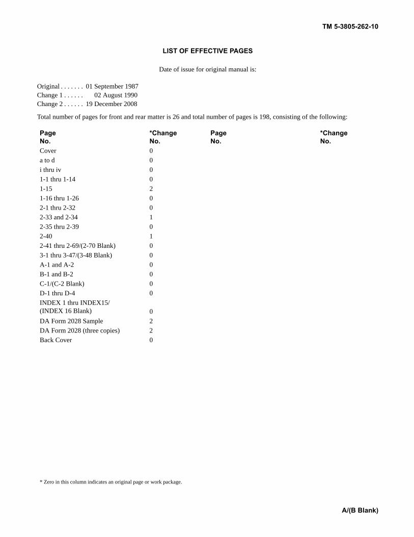
LIST OF EFFECTIVE PAGES
Date of issue for original manual is:
Original . . . . . . . 01 September 1987Change 1 . . . . . . 02 August 1990 Change 2 . . . . . . 19 December 2008
Total number of pages for front and rear matter is 26 and total number of pages is 198, consisting of the following:
PageNo.
*ChangeNo.
PageNo.
*ChangeNo.
Cover 0a to d 0i thru iv 01-1 thru 1-14 01-15 21-16 thru 1-26 02-1 thru 2-32 02-33 and 2-34 12-35 thru 2-39 02-40 12-41 thru 2-69/(2-70 Blank) 03-1 thru 3-47/(3-48 Blank) 0A-1 and A-2 0B-1 and B-2 0C-1/(C-2 Blank) 0D-1 thru D-4 0INDEX 1 thru INDEX15/(INDEX 16 Blank) 0DA Form 2028 Sample 2DA Form 2028 (three copies) 2Back Cover 0
* Zero in this column indicates an original page or work package.

Change 2

ALPHABETICAL INDEX
TM 5-3805-262-10
Section III
APPENDIX A.
APPENDIX B.
APPENDIX C.
APPENDIX D.
Maintenance Procedures . . . . . . . . . . . . . . . . . . . . . . . . . . . . . . . . . . . . .
COMPONENTS OF END ITEM (COEI) AND BASICISSUE ITEMS (BII) LISTS
ADDITIONAL AUTHORIZATION LIST (AAL) . . . . . . . . . . . . . . . . . . . . . . . .
Page3-35
A-1
B-1C-1
D-1
Index 1
ii
TM 5-3805-262-10
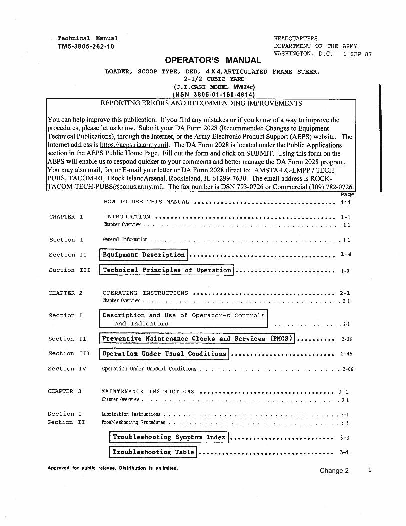
HOW TO USE THIS TECHNICAL MANUAL
This manual is designed to help you operate and maintain the MW24C loader. It’s di-vided into chapters, sections, and appendices. The chapters contain general informa-tion, operating procedures, and maintenance procedures. Chapters are divided intosections containing equipment description, principles of operation, description ofoperating controls and indicators, operating procedures, and troubleshooting andmaintenance procedures.
Appendices contain supplemental information which you require to operate and main-tain the loader.
Procedures in this manual tell you several things:
how to perform your PMCS and how oftenhow to start the loader including locations of all controlsand indicatorshow to operate the loader safely and efficientlyhow to troubleshoot the loaderhow to maintain the loader
All operating, troubleshooting, and maintenance procedures include illustrations tohelp you quickly locate the items on your equipment.
To quickly locate data in this manual, let’s say you want to find out the functionand use of the hydraulic control levers mounted-to the right of your seat. There aretwo ways you can locate this information.
a. Use the alphabetical index:
(1) Look on the front cover index for ALPHABETICAL INDEX.
(2) See that there is a black box drawn to the right of ALPHABETICAL INDEX.
(3) Flip through the pages starting at the back of this manual stopping at thepage that has a a black box in line with the box on the front cover index. This isthe alphabetical index.
(4) The alphabetical index contains subject matter listed in alphabetical se-quence. Look up Hydraulic control levers or Loader controls. In some cases, subjectmatter may be listed in several different ways to help you locateAcross from these two entries you will find the page number 2-19.
(5) Turn to page 2-19operation of the hydraulic
(b) Use the front cover
(1) Look on the frontTROLS AND INDICATORS.
(2) See that there is
where you will find a short functionalcontrol levers.
index:
cover index for DESCRIPTION AND USE OF
a black box drawn to the right of this
the information.
description and
OPERATOR’S CON-
entry.
iii
TM 5-3805-262-10
(3) Flip through the pages starting at the back of this manual stopping at thepage that has a a black box in line with the box on the front cover index. This isthe DESCRIPTION AND USE OF OPERATOR’S CONTROLS AND INDICATORS, page 2-1.
(4) Look in the section index and locate Loader Controls. It states the loadercontrols are provided in paragraph 2-10.
(5) Flipping through the pages, see that paragraph numbers are always locatedat the top of the left page. Now, go to paragraph 2-10 (page 2-21) to locate the in-formation you want.
This manual has been designed so that you can quickly locate data you are lookingfor. Either look in the ALPHABETICAL INDEX for the subject matter, refer to thefront cover index, table of contents, chapter index, or section index to locate thedata.
iv
TM 5-3805-262-10
Section
CHAPTER 1
INTRODUCTION
CHAPTER OVERVIEW
The purpose of this chapter is to acquaint you with themaintenance forms, records, and reports that you mustmaintain for the MW24C loader, to familiarize you withthe purpose and capabilities of the vehicle, and togive you a brief description of its different systemsand components.
Index
Title Page
I General Information . . . . . . . . . . . . . . . . . . . . . . . . . . . . . . . . . . . . . . . . . . . 1-1II Equipment Description . . . . . . . . . . . . . . . . . . . . . . . . . . . . . . . . . . . . . . . . . 1-4III Technical Principles of Operation . . . . . . . . . . . . . . . . . . . . . . . . . . . . . 1-9
Section I. GENERAL INFORMATION
ParaScope . . . . . . . . . . . . . . . . . . . . . . . . . . . . . . . . . . 1-1Maintenance Forms, and Records . . . . . . . . . . . . . 1-2Hand Receipt (-HR) Manuals . . . . . . . . . . . . . . . . . 1-3Reporting Equipment Improvement
Recommendations (EIR’S) . . . . . . . . . . . . . . . . . 1-4Warranty Information . . . . . . . . . . . . . . . . . . . . . . . 1-5Orientation . . . . . . . . . . . . . . . . . . . . . . . . . . . . . . . . 1-6List of Abbreviations . . . . . . . . . . . . . . . . . . . . . . 1-7
NOTE
The equipment described herein is non-metric and does notrequire metric common or special tools; therefore, metricunits are not supplied. Tactical instructions for sake ofclarity will also remain non-metric.
a. Type of Manual. Operator’s Manual, including operating, maintenance, andtroubleshooting instructions.
b. Model Number and Equipment Name. MW24C Diesel Engine Driven, 4 by 4, Articu-lated Frame Steer, 2-1/2 Cubic Yard Scoop Type Loader.
1-1
1-1.
TM 5-3805-262-10
c. Purpose of Equipment. Loading trucks from stockpiles, stockpiling materiel,and excavating undisturbed and compacted soil. Unit also used as a clamshell tohandle irregular shaped objects, as a dozer for general bulldozer work, and as ascraper.
1-2. MAINTENANCE FORMS,AND RECORDS
Department of the Army forms and procedures used for equipment maintenance will bethose prescribed by DA PAM 738-750, The Army Maintenance Management System (TAMMS).
1-3. HAND RECEIPT (–HR) MANUALS
This manual has a companion document with a TM number followed by “-HR” (whichstands for Hand Receipt). The TM 5-3805-262-10-HR consists of preprinted hand re-ceipts (DA Form 2062) that list end item related equipment (i.e., COEI, BII, andAAL) you must account for. As an aid to property accountability, additional -HR man-uals may be requisitioned as outlined in DA PAM 310–10.
1-4. REPORTING EQUIPMENT IMPROVEMENT RECOMMENDATIONS (EIR’S)
If your MW24C loader needs improvement, let us know. Send us an EIR. You, the user,are the only one who can tell us what you don’t like about your equipment. Let usknow why you don’t like the design or performance. Put it on an SF 368 (Quality De-ficiency Report). Mail it to us at: Commander, US Army Tank–Automotive Command,ATTN: AMSTA-MV Warren, MI 48397-5000. We’ll send you a reply.
1-5. WARRANTY INFORMATION
The MW24C loader is warranted by J.I.Case Company, Racine, Wisconsin for 15 monthsor 1500 hours of operation, whichever occurs first. Warranty starts on the date,found in block 23, DA Form 2408-9 in the logbook. Report all defects in material orworkmanship to your supervisor who will take appropriate action through your organi-zational shop.
1 - 6 . O R I E N T A T I O N
The loader bucket is mounted at the front of the MW24C and the engine faces therear. Controls for operating the bucket (lift arm, bucket tilt, clam) are located tothe right when you are sitting in the operator-s seat. All references to right,left, front , or rear are from the viewpoint of the operator when he is sitting inthe operator’s seat.
1-2

TM 5-3805-262-10
1-7. LIST OF ABBREVIATIONS
IABBREVIATION DEFINITION
A AfterAAL
AMPARATTNBBIIBRT.B.O.CCOEI
COMPTCONTCONVDDA
dBEIR
etc.
Authorized allow-ance list
AmperesArmy regulationsAttentionBeforeBasic issue itemsBrightBlack outCelsiusComponents of end
itemsCompartmentContinuedConverterDailyDepartment of the
ArmyDecibelEquipment improve-
ment recommenda-tions
Etcetera (unspeci-fied additionalthings )
ABBREVIATION I DEFINITION
FHHRLlb-ftMMIMOMPHNNEUT.ParaPMC S
PRESSpsi
Rrpm
SER.TEMPTMw
FahrenheitHigh (forward)Hand receiptLow (forward)Pounds feetMonthlyMichiganMissouriMiles per hourNeutralNeutralParagraphPreventive main-
tenance checksand services
PressurePounds per square
inchReverseRevolutions perminute
ServiceTemperatureTechnical ManualWeekly
1-3

TM 5-3805-262-10
Section II. EQUIPMENT DESCRIPTION
ParaEquipment Characteristics, Capabilities,and Features . . . . . . . . . . . . . . . . . . . . . . 1-8Location and Description of Major Components . . 1-9Differences Between Models . . . . . . . . . . . . . . . . . . . . . 1-10Equipment Data . . . . . . . . . . . . . . . . . . . . . . . . . . . . . . . . 1-11
1-8. EQUIPMENT CHARACTERISTICS, CAPABILITIES, AND FEATURES
a. Purpose of MW24C Loader. Loading trucks and railcars from stockpiles, stock-piling materiel, and excavating undisturbed and compacted soil. Unit also used as aclamshell to handle irregular shaped objects, as a dozer for general bulldozer work,and as a scraper.
b. Capabilities and Features.
(1) Two and one-half yard capacity bucket.(2) Operates over rough terrain.(3) Four speed ranges in forward; two speed ranges in reverse.(4) Declutch pedal disengages transmission during loader operation to provide
maximum hydraulic power when needed.(5) Diesel engine driven.(6) Power steering.(7) Power assisted air over hydraulic brakes.(8) Enclosed operator’s compartment.(9) Auxiliary steering automatically cuts-in if primary steering is disabled.(10) Bucket height control to automatically stop loader lift arms at a prese-
lected dump height.(11) Bucket return-to-dig control to automatically return bucket to preselected
position.(12) Four-in-one bucket used as a scraper, blade, clamshell, or standard buck-
et .(13) Ford depths up to 30 inches.(14) Collapsible steering wheel for air transport.
1-9. LOCATION AND DESCRIPTION OF MAJOR COMPONENTS
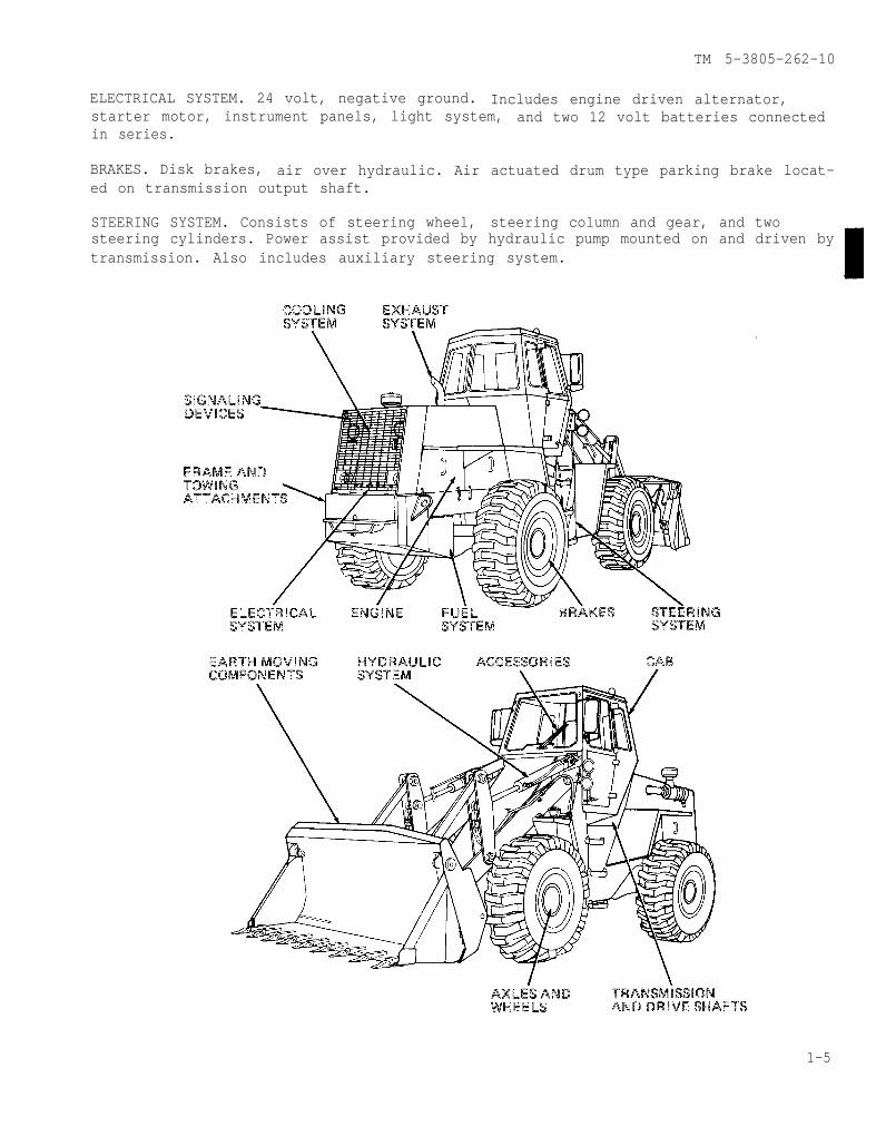
ENGINE. J.I.Case Model A504BD Diesel engine having a displacement of 504 cubic in-ches. Accessories mounted on and considered a part of the engine include the alter-nator, air compressor, starting motor, fuel injection pump, and fuel filters.
FUEL SYSTEM. Consists of fuel injectors, fuel injection pump, electric fuel pump,air cleaner, fuel filters, and cold start kit.
EXHAUST SYSTEM. Consists of muffler and exhaust pipe. Muffler mounted on top of en-gine.
COOLING SYSTEM. Includes radiator mounted in rear of loader, thermostat and housing,engine driven water pump, and fan.
1-4
TM 5-3805-262-10
ELECTRICAL SYSTEM. 24 volt, negative ground. Includes engine driven alternator,starter motor, instrument panels, light system, and two 12 volt batteries connectedin series.
BRAKES. Disk brakes, air over hydraulic. Air actuated drum type parking brake locat-ed on transmission output shaft.
STEERING SYSTEM. Consists of steering wheel, steering column and gear, and twosteering cylinders. Power assist provided by hydraulic pump mounted on and driven bytransmission. Also includes auxiliary steering system.
1-5

TM 5-3805-262-10
FRAME AND TOWING ATTACHMENTS. Two section frame consisting of front and rear chas-sis; drawbar pin located at rear of loader.
SIGNALING DEVICES. Consists of back-up alarm and turn signals. Back-up alarm locatedat rear of loader; sounds when transmission is shifted into reverse. Turn signals lo-cated at top of cab; turn signal switch mounted on steering column.
TRANSMISSION AND DRIVE SHAFTS. Four speeds in forward and two speeds in reverse. Hasdeclutch feature which permits neutralizing transmission. Three drive shafts used totransmit power to front and rear axles.
AXLES AND WHEELS. Standard planetary axles; pneumatic tires.
CAB. Fully enclosed and removable for shipment purposes when necessary. With doors,windows, and front and rear windshields.
ACCESSORIES. Includes air horn and control valve, windshield washer and wiper, out-side mirrors, heater, and fan defrosters.
HYDRAULIC SYSTEM. Consists of hydraulic main pump assembly/steering pump, controlvalve assembly, hydraulic cylinders (lift arm, bucket tilt, and clam), hydraulic re-servoir, and hydraulic filter.
EARTHMOVING COMPONENTS. Includes bucket lift arms and pivot assemblies and loaderbucket assembly.
1-10. DIFFERENCES BETWEEN MODELS
There are no differences between models of the MW24C loader.
1-11. EQUIPMENT DATA
Manufacturer . . . . . . . . . . . . . . . . . . . . . . . . . . . J.I. CaseModel . . . . . . . . . . . . . . . . . . . . . . . . . . . . . . . . . . . . . . . . . . . . . . . . MW24C
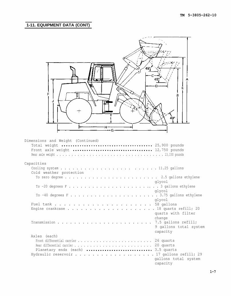
Dimensions and WeightOverall operating height (A) . . . . . . . . . . . . . . . . . . . . . . . . 16 feet, 1-1/2 inchesDump clearance at maximum height,
45 degrees dump (B) . . . . . . . . . . . . . . . . . . . . . . . . . . . . 9 feetDump reach at maximum height,
45 degrees dump (C) . . . . . . . . . . . . . . . . . . . . . . . . . . . . 3 feet, 1 inchDump reach at 7 feet dump height,
45 degrees dump (D) . . . . . . . . . . . . . . . . . . . . . . . . . . 4 feet, 5 inchesHeight to bucket hinge pin (E) . . . . . . . . . . . . . . . . . . . . . . 12 feet, 2-1/2 inchesMaximum shipping height (F) . . . . . . . . . . . . . . . . . . . . . . . . . 10 feet, 10-1/2 inchesOverall length, bucket on ground (G) . . . . . . . . . . . . . . 22 feet, 5-1/2 inchesOverall width l . . . . . . . . . . . . . . . . . . . . . . . . . . . . . . . . . . . . . . 94-1/2 inchesWheel base (H) . . . . . . . . . . . . . . . . . . . . . . . . . . . . . . 10 feet, 1-1/2 inchesTire tread . . . . . . . . . . . . . . . . . . . . . . . . . . . . . . . . . . . . . . . . . . 77 inchesGround clearance (I) . . . . . . . . . . . . . . . . . . . . . . . . . 16 inchesHeight to top of steering wheel (J) . . . . . . . . . . 106-1/2 inchesOverall height without cab . . . . . . . . . . . . . . . . . . . . . . . . . . 106-1/2 inchesWidth overtires . . . . . . . . . . . . . . . . . . . . . . . . . . . . . . . . . . . . 100 inches
1-6
TM 5-3805-262-10
1-11. EQUIPMENT DATA (CONT)
Dimensions and Weight (Continued)Total weight 25,900 poundsFront axle weight 12,750 poundsRear axle weight . . . . . . . . . . . . . . . . . . . . . . . . . . . . . . . . . . . . 13,150 pounds
CapacitiesCooling system . . . . . . . . . . . . . . . . . . . . . . . . 11.25 gallonsCold weather protection
To zero degree . . . . . . . . . . . . . . . . . . . . . . . . 2.5 gallons ethyleneglycol
To -20 degrees F . . . . . . . . . . . . . . . . . . . . .. . . 3 gallons ethyleneglycol
To -40 degrees F . . . . . . . . . . . . . . . . . . . . . . 3.75 gallons ethyleneglycol
Fuel tank . . . . . . . . . . . . . . . . . . . . . 58 gallonsEngine crankcase . . . . . . . . . . . . . . . . . . . . 18 quarts refill; 20
quarts with filterchange
Transmission . . . . . . . . . . . . . . . . . . . . . . . 7.5 gallons refill;9 gallons total systemcapacity
Axles (each)Front differential carrier . . . . . . . . . . . . . . . . . . . . . . . . 26 quartsRear differential carrier . . . . . . . . . . . . . . . . . . . . . . . . . 20 quartsPlanetary ends (each) 3.5 quarts
Hydraulic reservoir . . . . . . . . . . . . .. . . . . . 17 gallons refill; 29gallons total systemcapacity
1-7
TM 5-3805-262-10
1-11. EQUIPMENT DATA (CONT)
Loader bucketWidth . . . . . . . . . . . . . . . . . . . . . . . . . . . . . . . . . . . . . . . . . . . . . . . 101 inchesRated capacity . . . . . . . . . . . . . . . . . . . . . . . . . . . . . . . . . . . . . . 2-1/2 yards
TiresSize . . . . . . . . . . . . . . . . . . . . . . . . . . . . . . . . . . . . . . . . . . . . . . . . 20.5 X 25Air pressure . . . . . . . . . . . . . . . . . . . . . . . . . . . . . . . . . . . . . . . . 40 psi
Performance speeds (MPH)Forward
1st low range . . . . . . . . . . . . . . . . . . . . . . . . . . . . . . . . . . . . . 2.62nd low range . . . . . . . . . . . . . . . . . . . . . . . 6.53rd high range . . . . . . . . . . . . . . . . . . . . . . . . . 11.44th high range . . . . . . . . . . . . . . . . . . . . . . . . . 22.2
Reverse1st . . . . . . . . . . . . . . . . . . . . . . . . . . . . . . . . . . . . 3.62nd . . . . . . . . . . . . . . . . . . . . . . . . . . . . . . . . . . . . . . . . . . 8.7
Military Load ClassificationEmpty . . . . . . . . . . . . . . . . . . . . . . . . . . . . . . . . . . . . . . . . . . . . . . . 13Loaded . . . . . . . . . . . . . . . . . . . . . . . . . . . . . . . . . . . . . 21
1-8
TM 5-3805-262-10
Section III. TECHNICAL PRINCIPLES OF OPERATION
ParaFuel System . . . . . . . . . . . . . . . . 1-12Cooling System . . . . . . . . . . . . . . . 1-13Electrical System . . . . . . . . . . . . . . 1-14
Vehicle Lights . . . . . . . . . . . . 1-14aSwitches and Circuit Breakers . 1-14bWarning Indicators . . . . . . . .1-14cGages . . . . . . . . . . . . . . 1-14dSlave Receptacle and Hour-
meter/Tachometer . . . . . . . . 1-14eBatteries and Cables . . . . . . . . 1-14fWiring Harnesses . . . . . . . . .. 1-14g
1-12. FUELSYSTEM
ParaTransmission and Drive Shafts . . . . 1-15
Transmission Controls . . . . . . . . . 1-15aDrive Shafts . . . . . . . . . . .. 1-15b
Brakes . . . . . . . . . . . . . . . . . 1-16Steering System . . . . . . . . . . . . . . . . . . 1-17Frame and Towing Attachments . . . . . 1-18Cab 1-19Accessories . . . . . . . . . . . . . . . . . . . . . . 1-20Hydraulic System . . . . . . . . . . . . . . . . . 1-21Signaling Devices . . . . . . . . . . . . . . . . 1-22Earthmoving Components . . . . . . . . . . . 1-23
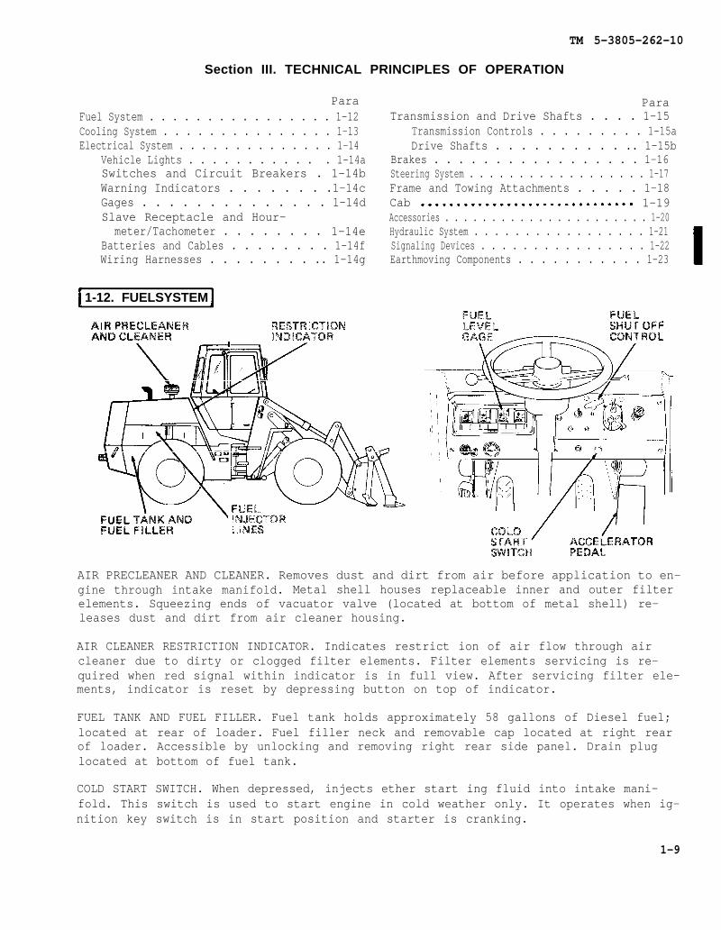
AIR PRECLEANER AND CLEANER. Removes dust and dirt from air before application to en-gine through intake manifold. Metal shell houses replaceable inner and outer filterelements. Squeezing ends of vacuator valve (located at bottom of metal shell) re-leases dust and dirt from air cleaner housing.
AIR CLEANER RESTRICTION INDICATOR. Indicates restrict ion of air flow through aircleaner due to dirty or clogged filter elements. Filter elements servicing is re-quired when red signal within indicator is in full view. After servicing filter ele-ments, indicator is reset by depressing button on top of indicator.
FUEL TANK AND FUEL FILLER. Fuel tank holds approximately 58 gallons of Diesel fuel;located at rear of loader. Fuel filler neck and removable cap located at right rearof loader. Accessible by unlocking and removing right rear side panel. Drain pluglocated at bottom of fuel tank.
COLD START SWITCH. When depressed, injects ether start ing fluid into intake mani-fold. This switch is used to start engine in cold weather only. It operates when ig-nition key switch is in start position and starter is cranking.
1-9

TM 5-3805-262-10
1-12. FUEL SYSTEM (CONT)
ACCELERATOR PEDAL. Depressing pedal with foot increases fuel flow and engine speed.Releasing pedal decreases fuel flow and engine speed. Pedal is spring loaded to re-turn to low speed position when released.
FUEL LEVEL GAGE. Electrically operated meter type. With ignition key switch in ONposition, FUEL LEVEL gage indicates quantity of fuel remaining in fuel tank.
FUEL SHUT OFF CONTROL (ENGINE STOP). Cable connected to fuel injection pump fuelshut off lever. When pulled out, fuel is unable to enter fuel injection pump effec-tively stopping engine operation.
FUEL INJECTOR LINES. Fuel is routed to six fuel injectors from fuel injection pumpthrough rigid metal tubes. Return (leak-off) fuel is routed through rigid metaltubes interconnecting each fuel injector back to fuel injection pump.
1-13. COOLING SYSTEM
RADIATOR. Located at rear of loader. Engine coolant circulated through radiator giv-ing up its heat to air stream developed by belt driven fan. Cooled coolant drawnfrom bottom of radiator by water pump and discharged into lower part of cylinderblock. Radiator has oil cooler built into its bottom for cooling transmission hy-draulic oil. Radiator cap accessible by unlocking and raising access panel locatedat top rear of loader.
WATER TEMP GAGE. Indicates engine coolant temperature. Normal operating temperatureis in green zone.
1-10
TM 5-3805-262-10
1-14. ELECTRICAL SYSTEM
a. Vehicle Lights.
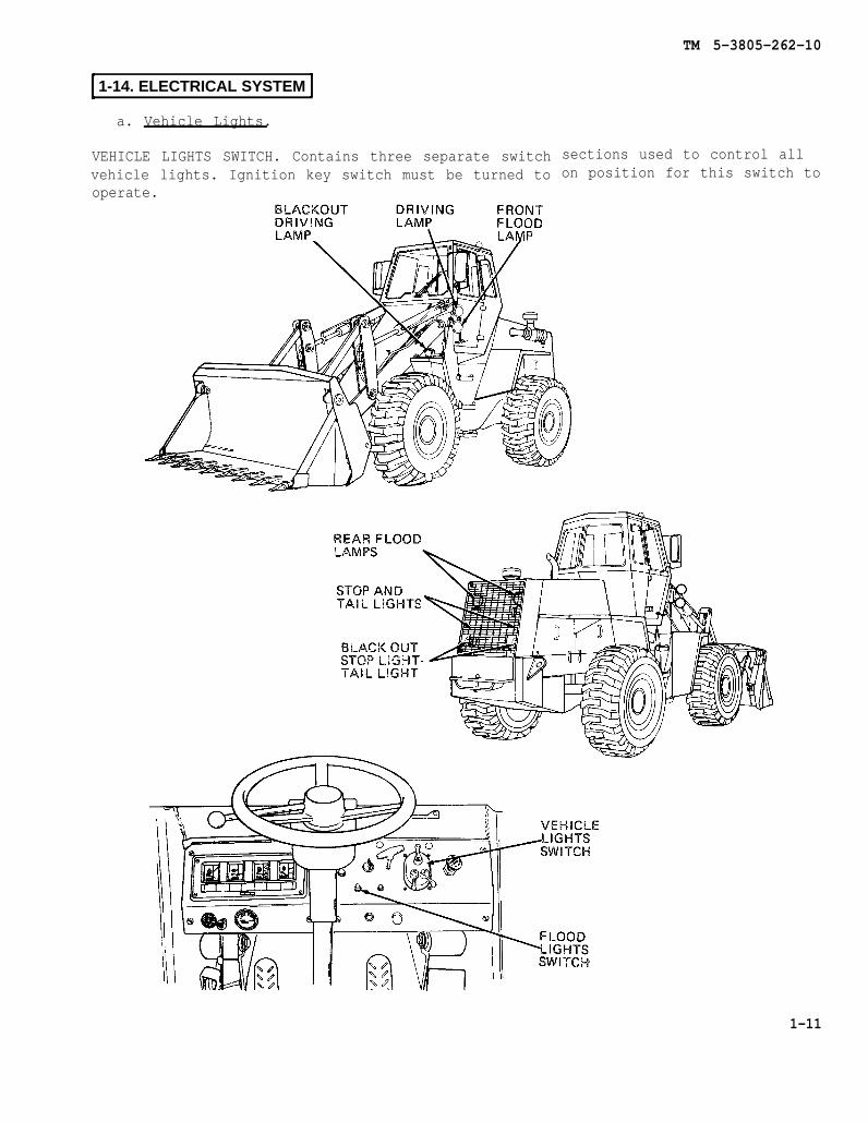
VEHICLE LIGHTS SWITCH. Contains three separate switchvehicle lights. Ignition key switch must be turned tooperate.
sections used to control allon position for this switch to
1-11
TM 5-3805-262-10
1-14. ELECTRICAL SYSTEM (CONT)
a. Vehicle Lights (Cont).
FLOOD LIGHTS SWITCH. Independently turn front and rear flood lights on and off. Ve-hicle lights switch must be in SER. DRIVE position for this switch to operate.
BLACK OUT DRIVING LAMP. Mounted on left front fender. Provides forward black out il-lumination during tactical operations. Controlled by vehicle lights switch.
FRONT FLOOD LAMPS. Two sealed beam type lamps mounted on mounting brackets at frontleft and right sides of loader. Illuminate work area in front of loader. Turned onand off with FLOOD LIGHTS switch.
DRIVING LAMPS. Two sealed beam type lamps mounted above flood lamps at left andright sides of loader. Illuminate area in front of loader for driving at night.
REAR FLOOD LAMPS. Two sealed beam type lamps mounted on mounting brackets at rearleft and right sides of loader within radiator guard and behind radiator grille. Il-luminate work area in rear of loader. Turned on and off with FLOOD LIGHTS switch.
STOP AND TAIL LIGHTS. Two light assemblies mounted on brackets within radiatorguard, behind radiator grille. Includes incandescent lamp and red plastic lens. Taillights turned on by vehicle lights switch. Stop lights normally off; turned on bypressing brake treadle valve or declutch treadle valve.
BLACK OUT STOP LIGHT-TAIL LIGHT. Two light assemblies mounted in protective metalhousings within radiator guard, behind radiator grille. Each assembly contains twoincandescent lamps. Provide stop light and tail light illumination during tacticaloperations. Tail lights turned on and off by vehicle lights switch. Stop lights arenormally off; turned on by pressing brake treadle valve or declutch treadle valve.
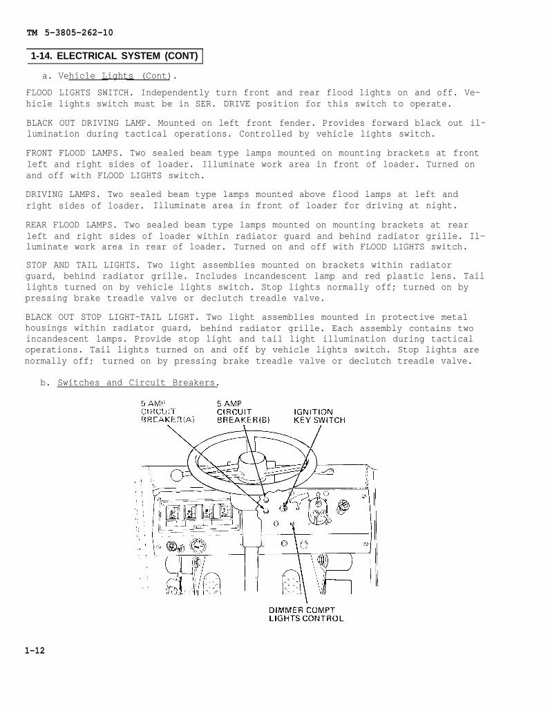
b. Switches and Circuit Breakers.
1-12
TM 5-3805-262-10
IGNITION KEY SWITCH. Four position key switch controls power to all vehicle elec-trical circuits.
DIMMER COMPT LIGHTS CONTROL. Rheostat. Controls brightness of left instrument panelcluster illumination lamps, voltmeter gage illumination lamp, and cab dome light.
5 AMP CIRCUIT BREAKER (A). Resettable circuit breaker. Protects auxiliary steeringcircuit, air brake pressure switch and buzzer, gages, warning lights, and voltmeter,cab relay solenoid, and electric fuel pump.
5 AMP CIRCUIT BREAKER (B). Resettable circuit breaker. Protects return-to-dig andbucket height control circuits.
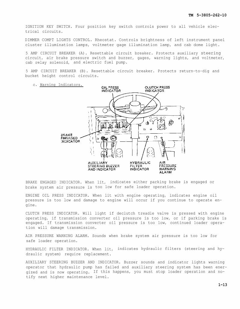
c. Warning Indicators.
BRAKE ENGAGED INDICATOR. When lit, indicates either parking brake is engaged orbrake system air pressure is too low for safe loader operation.
ENGINE OIL PRESS INDICATOR. When lit with engine operating, indicates engine oilpressure is too low and damage to engine will occur if you continue to operate en-gine.
CLUTCH PRESS INDICATOR. Will light if declutch treadle valve is pressed with engineoperating, if transmission converter oil pressure is too low, or if parking brake isengaged. If transmission converter oil pressure is too low, continued loader opera-tion will damage transmission.
AIR PRESSURE WARNING ALARM. Sounds when brake system air pressure is too low forsafe loader operation.
HYDRAULIC FILTER INDICATOR. When lit, indicates hydraulic filters (steering and hy-draulic system) require replacement.
AUXILIARY STEERING BUZZER AND INDICATOR. Buzzer sounds and indicator lights warningoperator that hydraulic pump has failed and auxiliary steering system has been ener-gized and is now operating. If this happens, you must stop loader operation and no-tify next higher maintenance level.
1-13
1-14.
TM 5-3805-262-10
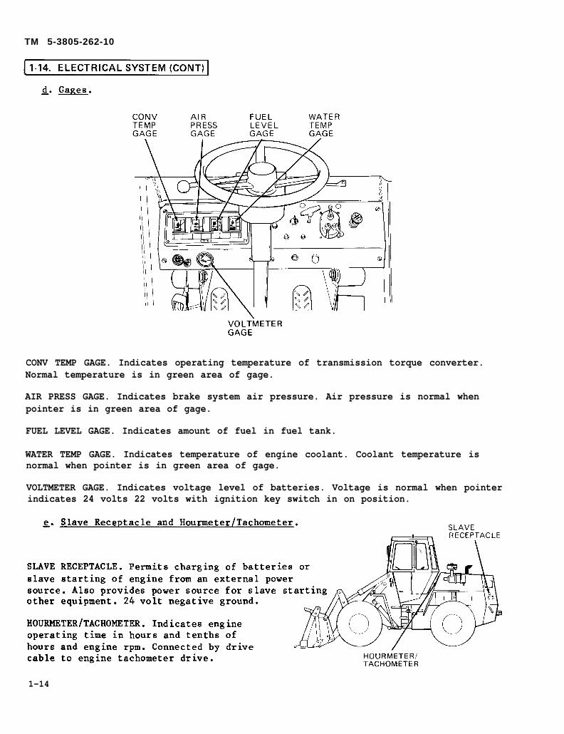
CONV TEMP GAGE. Indicates operating temperature of transmission torque converter.Normal temperature is in green area of gage.
AIR PRESS GAGE. Indicates brake system air pressure. Air pressure is normal whenpointer is in green area of gage.
FUEL LEVEL GAGE. Indicates amount of fuel in fuel tank.
WATER TEMP GAGE. Indicates temperature of engine coolant. Coolant temperature isnormal when pointer is in green area of gage.
VOLTMETER GAGE. Indicates voltage level of batteries. Voltage is normal when pointerindicates 24 volts 22 volts with ignition key switch in on position.
1-14

TM 5-3805-262-10
Change 2 1-15
f. Batteries and Cables.
BATTERY CABLES. Six cables used. Battery interconnecting cable connects first battery negative terminal to sec-ond battery positive terminal. Ground cables connected between second battery negative post, battery disconnect switch, andnegative terminal of slave receptacle. A separate ground cable connects from output of battery disconnect switch to the startermotor terminal. Ground cables connected at battery terminal by terminal lug. Positive cable connected between first batterypositive terminal, starter solenoid, and slave receptacle positive terminal. Positive cables connected at battery terminal by ter-minal lug.
BATTERY DISCONNECT SWITCH. Isolates ground from electrical system when turned off. Slave receptacleremains connected to negative battery terminal. Battery disconnect switch provides ground to the electrical system when ener-gized.
TM 5-3805-262-10
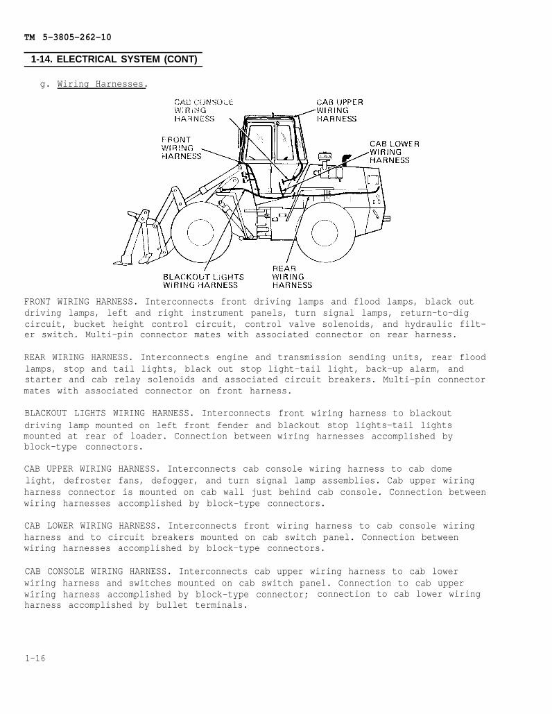
g. Wiring Harnesses.
1-14. ELECTRICAL SYSTEM (CONT)
FRONT WIRING HARNESS. Interconnects front driving lamps and flood lamps, black outdriving lamps, left and right instrument panels, turn signal lamps, return-to-digcircuit, bucket height control circuit, control valve solenoids, and hydraulic filt-er switch. Multi–pin connector mates with associated connector on rear harness.
REAR WIRING HARNESS. Interconnects engine and transmission sending units, rear floodlamps, stop and tail lights, black out stop light-tail light, back-up alarm, andstarter and cab relay solenoids and associated circuit breakers. Multi-pin connectormates with associated connector on front harness.
BLACKOUT LIGHTS WIRING HARNESS. Interconnectsdriving lamp mounted on left front fender andmounted at rear of loader. Connection betweenblock-type connectors.
front wiring harness to blackoutblackout stop lights-tail lightswiring harnesses accomplished by
CAB UPPER WIRING HARNESS. Interconnects cab console wiring harness to cab domelight, defroster fans, defogger, and turn signal lamp assemblies. Cab upper wiringharness connector is mounted on cab wall just behind cab console. Connection betweenwiring harnesses accomplished by block–type connectors.
CAB LOWER WIRING HARNESS. Interconnects front wiring harness to cab console wiringharness and to circuit breakers mounted on cab switch panel. Connection betweenwiring harnesses accomplished by block-type connectors.
CAB CONSOLE WIRING HARNESS. Interconnects cab upper wiring harness to cab lowerwiring harness and switches mounted on cab switch panel. Connection to cab upperwiring harness accomplished by block-type connector; connection to cab lower wiringharness accomplished by bullet terminals.
1-16

TM 5-3805-262-10
1-15. TRANSMISSION AND DRIVE SHAFTS
a. Transmission Controls.
TRANSMISSION CONTROL LEVER. Selects one of four positions: low range forward, highrange forward, neutral, and low range reverse.
DECLUTCH TREADLE VALVE. Applies service brakes, lights stop lights at rear of load-er, disengages transmission, and lights CLUTCH PRESS indicator. Used to disengagetransmission to provide maximum hydraulic power for loader operation.
b. Drive Shafts.
FRONT DRIVE SHAFT. Connected between center drive shaft and front axle. Connected tofront axle yoke by universal joint and to center drive shaft by yoke with internalsplines. Rear of front drive shaft supported by a bearing.
CENTER DRIVE SHAFT. Connected betweentransmission output shaft and front driveshaft. Connection accomplished by univer-sal joints.
REAR DRIVE SHAFT. Connected between trans-mission output shaft and rear axle by uni-versal joints.
1-17
TM 5-3805-262-10
1-16. BRAKES
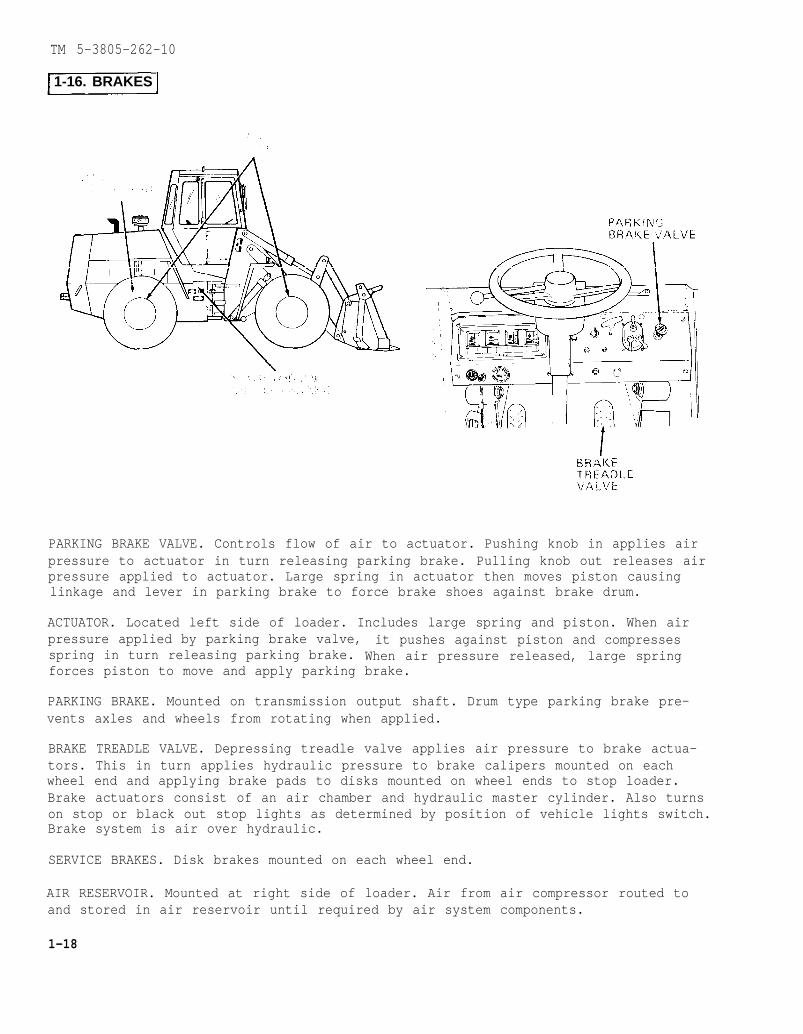
PARKING BRAKE VALVE. Controls flow of air to actuator. Pushing knob in applies airpressure to actuator in turn releasing parking brake. Pulling knob out releases airpressure applied to actuator. Large spring in actuator then moves piston causinglinkage and lever in parking brake to force brake shoes against brake drum.
ACTUATOR. Located left side of loader. Includes large spring and piston. When airpressure applied by parking brake valve, it pushes against piston and compressesspring in turn releasing parking brake. When air pressure released, large springforces piston to move and apply parking brake.
PARKING BRAKE. Mounted on transmission output shaft. Drum type parking brake pre-vents axles and wheels from rotating when applied.
BRAKE TREADLE VALVE. Depressing treadle valve applies air pressure to brake actua-tors. This in turn applies hydraulic pressure to brake calipers mounted on eachwheel end and applying brake pads to disks mounted on wheel ends to stop loader.Brake actuators consist of an air chamber and hydraulic master cylinder. Also turnson stop or black out stop lights as determined by position of vehicle lights switch.Brake system is air over hydraulic.
SERVICE BRAKES. Disk brakes mounted on each wheel end.
AIR RESERVOIR. Mounted at right side of loader. Air from air compressor routed toand stored in air reservoir until required by air system components.
1-18
TM 5-3805-262-10
1-17. STEERING SYSTEM
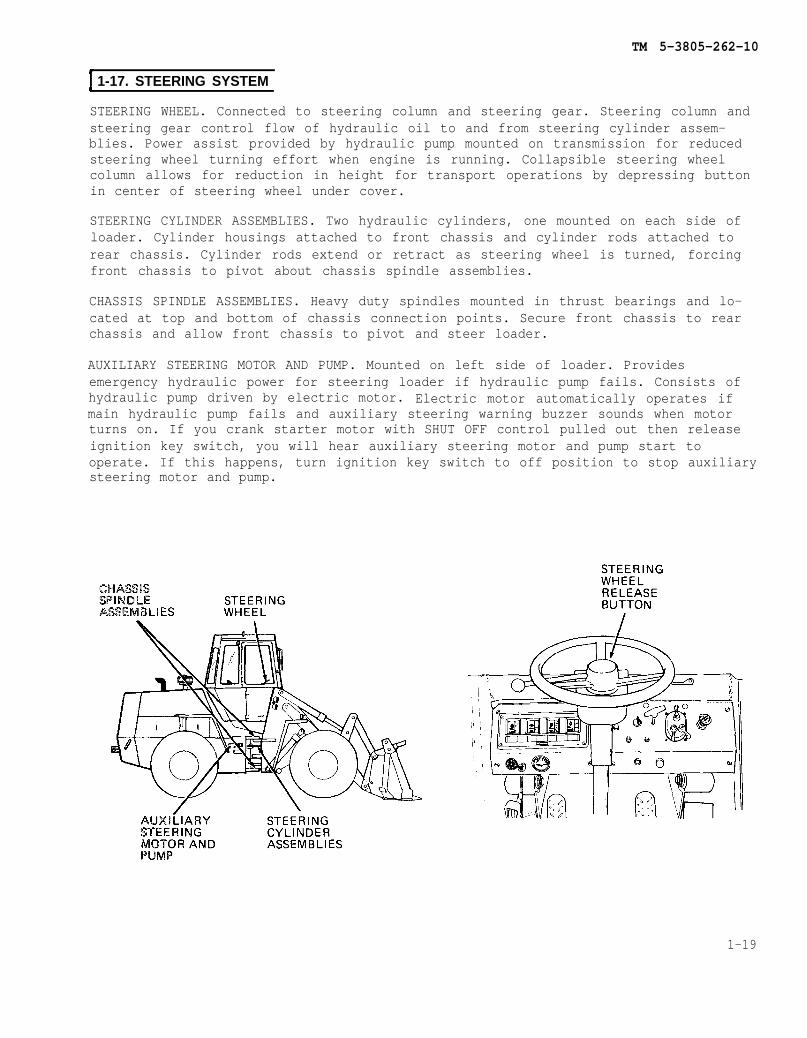
STEERING WHEEL. Connected to steering column and steering gear. Steering column andsteering gear control flow of hydraulic oil to and from steering cylinder assem-blies. Power assist provided by hydraulic pump mounted on transmission for reducedsteering wheel turning effort when engine is running. Collapsible steering wheelcolumn allows for reduction in height for transport operations by depressing buttonin center of steering wheel under cover.
STEERING CYLINDER ASSEMBLIES. Two hydraulic cylinders, one mounted on each side ofloader. Cylinder housings attached to front chassis and cylinder rods attached torear chassis. Cylinder rods extend or retract as steering wheel is turned, forcingfront chassis to pivot about chassis spindle assemblies.
CHASSIS SPINDLE ASSEMBLIES. Heavy duty spindles mounted in thrust bearings and lo-cated at top and bottom of chassis connection points. Secure front chassis to rearchassis and allow front chassis to pivot and steer loader.
AUXILIARY STEERING MOTOR AND PUMP. Mounted on left side of loader. Providesemergency hydraulic power for steering loader if hydraulic pump fails. Consists ofhydraulic pump driven by electric motor. Electric motor automatically operates ifmain hydraulic pump fails and auxiliary steering warning buzzer sounds when motorturns on. If you crank starter motor with SHUT OFF control pulled out then releaseignition key switch, you will hear auxiliary steering motor and pump start tooperate. If this happens, turn ignition key switch to off position to stop auxiliarysteering motor and pump.
1-19

TM 5-3805-262-10
1-18. FRAME AND TOWING ATTACHMENTS
ENGINE SIDE PANELS. Constructed of sheet metal. Secured to rear chassis by latches:two for each panel. Provide access to engine compartment.
DRAWBAR PIN. Constructed of heavy steel. Provides means of attaching pintle hook ordrawbar for towing loader or using loader as tow vehicle.
TRUNNION ASSEMBLY. Rear axle mounted on trunnion assembly providing rear axle oscil-lation. Allows rear chassis to pivot when operating over rough terrain.
TRANSPORT/SERVICE LINK. Constructed of heavy gage steel. Must be in operating posi-tion during loader operation. Prevents loader from pivoting therefore no steeringcontrol when in engaged position. Must be in engaged position when personnel areworking in area between front and rear chassis, when loader is being airlifted ortransported, or loader is jacked up.
FRONT ACCESS DOOR. Constructed of sheet metal. Provides access to hydraulic reser-voir and windshield washer reservoir. Hydraulic reservoir sight gage located justbelow access door.
1-20

TM 5-3805-262-10
1-19. CAB
WINDSHIELDS AND SIDE WINDOWS. Front windshield, rear windshields, and two side win-dows provide operator with a 360 degree field of vision.
DOOR ASSEMBLIES. Two door assemblies. Each door assembly consists of an upper and alower door assembly. Upper door assembly can be unlatched from lower door assemblyand latched in full open position. Upper door assembly includes glazing.
SLINGING EYES. Two slinging eyes located at top of cab to aid in cab removal and in-stallation.
1-21

TM 5-3805-262-10
1-20. ACCESSORIES
WINDSHIELD WASHER. Front windshield washer. Air actuated. Nozzle mounted just belowfront windshield. Depressing control located on left instrument panel applies airpressure to fluid reservoir in turn forcing fluid from reservoir through hose tospray out nozzle onto windshield.
OUTSIDE MIRRORS. One mounted on each side of cab. Easily adjusted by operator.
1-22
TM 5-3805-262-10
CAB INSIDE MIRROR. Mounted inside cab, right side.
WINDSHIELD WIPER AND MOTOR. Electric motor driven wiper. Wiper motor mounted direct-ly behind wiper arm.
DEFROSTER ASSEMBLY. Mounted at cab ceiling. Directs air over front windshield toclear windshield of fog.
CAB DOME LIGHT. Located behind defogger assembly. Includes on-off switch. providesillumination for cab. Brightness controlled by DIMMER COMPT LIGHTS control mountedon right instrument panel and vehicle lights switch auxiliary switch. Vehicle lightsswitch main switch and auxiliary switch must be in any position other than OFF forthis light to operate.
DEFOGGER FANS. Two fans. Mounted above and to sides of rear windshield. Each fanincludes LOW-OFF-HIGH switch and is directionally adjustable to direct airflow overrear windshields.
CAB HEATER. Located to left of operator’s seat. Utilizes heat from engine coolant toheat cab. Includes electric motor driven fan.
CONSOLE SWITCH PANEL. Contains switches and circuit breakers for defroster, heaterfan, and front wiper circuits.
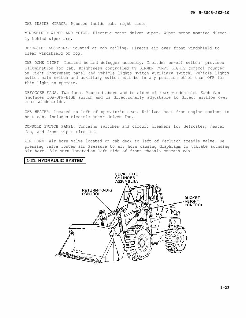
AIR HORN. Air horn valve located on cab deck to left of declutch treadle valve. De-pressing valve routes air Pressure to air horn causing diaphragm to vibrate soundingair horn. Air horn located
1-21. HYDRAULIC SYSTEM
on left side of front chassis beneath cab.
1-23
TM 5-3805-262-10
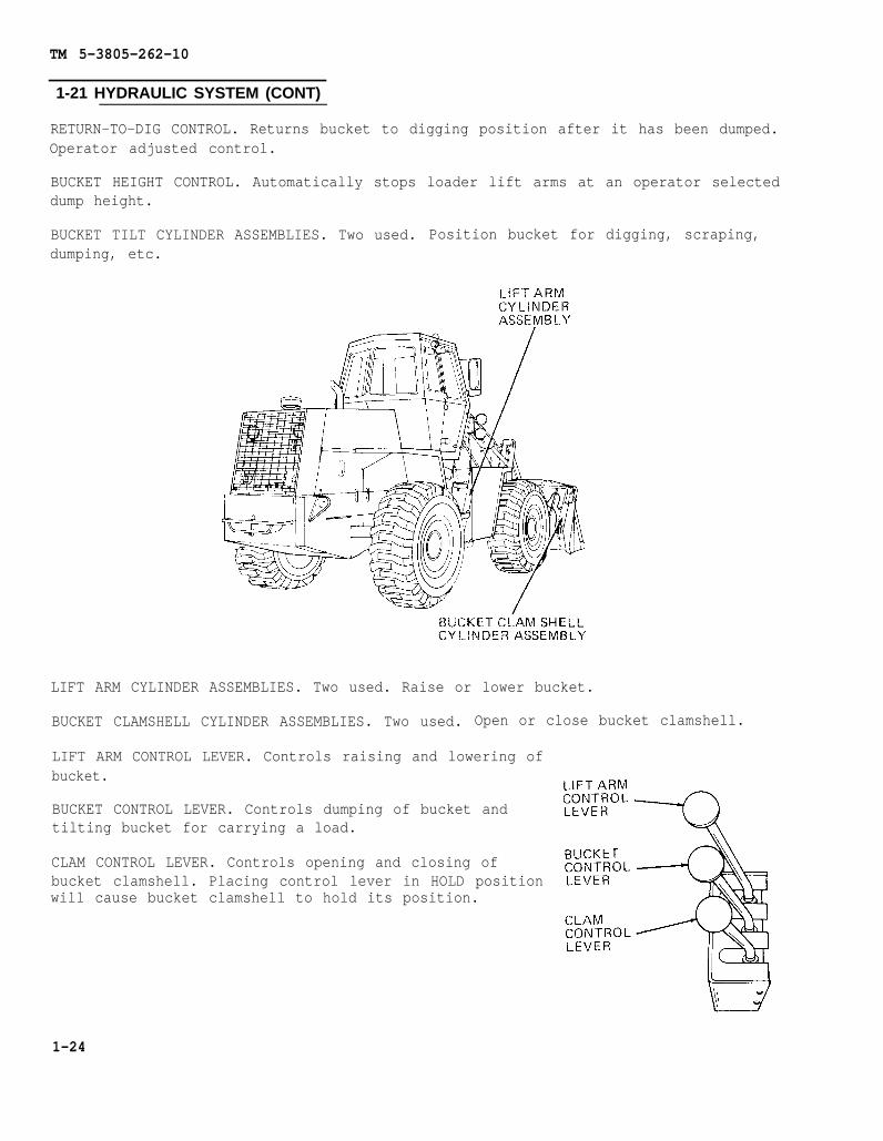
1-21 HYDRAULIC SYSTEM (CONT)
RETURN-TO-DIG CONTROL. Returns bucket to digging position after it has been dumped.Operator adjusted control.
BUCKET HEIGHT CONTROL. Automatically stops loader lift arms at an operator selecteddump height.
BUCKET TILT CYLINDER ASSEMBLIES. Two used. Position bucket for digging, scraping,dumping, etc.
LIFT ARM CYLINDER ASSEMBLIES. Two used. Raise or lower bucket.
BUCKET CLAMSHELL CYLINDER ASSEMBLIES. Two used. Open or close bucket clamshell.
LIFT ARM CONTROL LEVER. Controls raising and lowering ofbucket.
BUCKET CONTROL LEVER. Controls dumping of bucket andtilting bucket for carrying a load.
CLAM CONTROL LEVER. Controls opening and closing ofbucket clamshell. Placing control lever in HOLD positionwill cause bucket clamshell to hold its position.
1-24

TM 5-3805-262-10
HYDRAULIC RESERVOIR. Located behind front access door. Oil filler cap located at topof reservoir.
SIGHT GAGE. Located at front of loader. Oil level must be seen in sight gage. If oillevel is not seen, hydraulic oil must be added.
1-22. SIGNALING DEVICES
BACK-UP ALARM. Electrically operated alarm located at rear of loader behind radiatorgrille. Sounds distinctive warning whenever transmission control lever is placed inreverse (R) position. Ignition key switch must be turned to on position before back-up alarm will sound.
1-25
TM 5-3805-262-10
1-22. SIGNALING DEVICES (CONT)
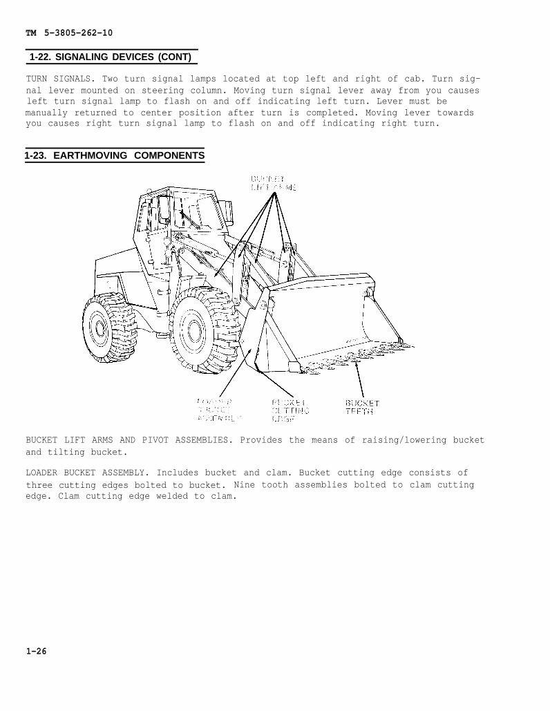
TURN SIGNALS. Two turn signal lamps located at top left and right of cab. Turn sig-nal lever mounted on steering column. Moving turn signal lever away from you causesleft turn signal lamp to flash on and off indicating left turn. Lever must bemanually returned to center position after turn is completed. Moving lever towardsyou causes right turn signal lamp to flash on and off indicating right turn.
1-23. EARTHMOVING COMPONENTS
BUCKET LIFT ARMS AND PIVOT ASSEMBLIES. Provides the means of raising/lowering bucketand tilting bucket.
LOADER BUCKET ASSEMBLY. Includes bucket and clam. Bucket cutting edge consists ofthree cutting edges bolted to bucket. Nine tooth assemblies bolted to clam cuttingedge. Clam cutting edge welded to clam.
1-26

TM 5-3805-262-10
CHAPTER 2
OPERATING INSTRUCTIONS
CHAPTER OVERVIEW
The purpose of this chapter is to familiarize you withthe equipment so that you can operate it safely,efficiently, and effectively.
Section
Index
Title PageI Description and Use of Operator's Controls and Indicators . . . . . 2-1II Preventive Maintenance Checks and Services (PMCS) . . . . . . . . . . . . . 2-26III Operation Under Usual Conditions . . . . . . . . . . . . . . . . . . . . 2-45IV Operation Under Unusual Conditions . . . . . . . . . . . . . . . . . . 2-66
Section I. DESCRIPTION AND USE OF OPERATOR’S CONTROLS AND INDICATORS
Instrument Panels . . . . . . . . . .Right Instrument Panel . . . . . . . .Left Instrument Panel . . . . . . . . .
Console Switch Panel . . . . . . . . . . . . .Switches and Control . . . . . . . . . .Circuit Breakers . . . . . . . . . . . . . .
Transmission Controls . . . . . . . . . . . .Brake and Throttle Controls . . . . . .Turn Signals and Flasher . . . . . . . . .
Para2-12-1a2-1b2-22-2a2-2b2-32-42-5
Rear Windshield Defogger Fans . . . .Dome Light Switch . . . . . . . . . . . . . . . .Upper and Lower Door Latches . . . . .Operator-s Seat . . . . . . . . . . . . . . . . . .Loader Controls . . . . . . . . . . . . . . . . . .Externally Mounted Controls and
Indicators . . . . . . . . . . . . . . . . . . . .Other Operator’s Controls and
Indicators . . . . . . . . . . . . . . . . . . . .
Para2-62-72-82-92-10
2-11
2-12
2-1
TM 5-3805-262-10
12-1. INSTRUMENT PANELS
a. Right Instrument Panel.
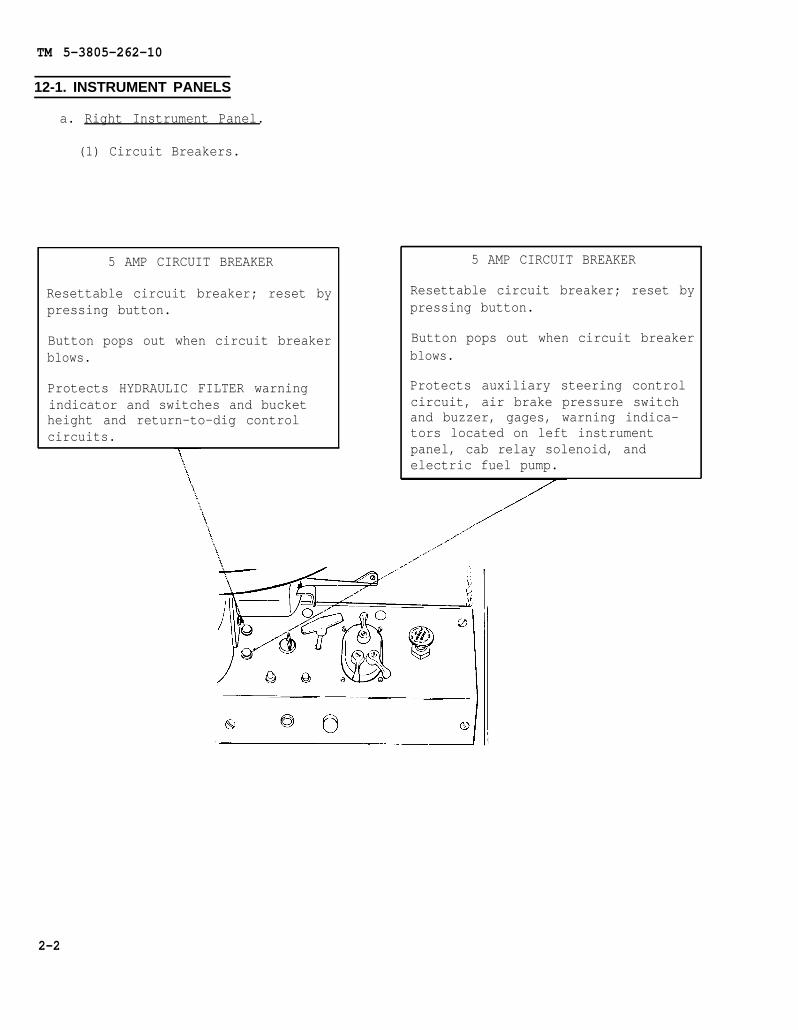
(1) Circuit Breakers.
5 AMP CIRCUIT BREAKER
Resettable circuit breaker; reset bypressing button.
Button pops out when circuit breakerblows.
Protects HYDRAULIC FILTER warningindicator and switches and bucketheight and return-to-dig controlcircuits.
5 AMP CIRCUIT BREAKER
Resettable circuit breaker; reset bypressing button.
Button pops out when circuit breakerblows.
Protects auxiliary steering controlcircuit, air brake pressure switchand buzzer, gages, warning indica-tors located on left instrumentpanel, cab relay solenoid, andelectric fuel pump.
2-2
TM 5-3805-262-10
2-1. INSTRUMENT PANELS (CONT)
a. Right Instrument Panel (Cont).
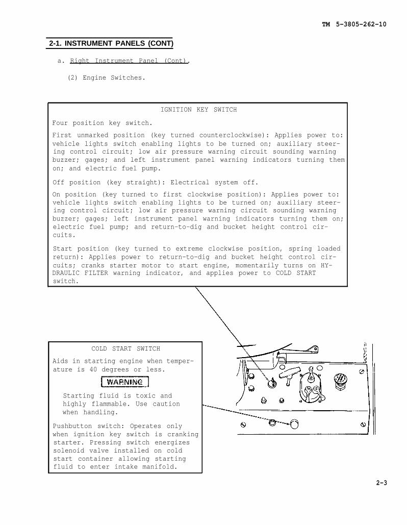
(2) Engine Switches.
IGNITION KEY SWITCH
Four position key switch.
First unmarked position (key turned counterclockwise): Applies power to:vehicle lights switch enabling lights to be turned on; auxiliary steer-ing control circuit; low air pressure warning circuit sounding warningbuzzer; gages; and left instrument panel warning indicators turning themon; and electric fuel pump.
Off position (key straight): Electrical system off.
On position (key turned to first clockwise position): Applies power to:vehicle lights switch enabling lights to be turned on; auxiliary steer-ing control circuit; low air pressure warning circuit sounding warningbuzzer; gages; left instrument panel warning indicators turning them on;electric fuel pump; and return-to-dig and bucket height control cir-cuits.
Start position (key turned to extreme clockwise position, spring loadedreturn): Applies power to return-to-dig and bucket height control cir-cuits; cranks starter motor to start engine, momentarily turns on HY-DRAULIC FILTER warning indicator, and applies power to COLD STARTswitch.
COLD START SWITCH
Aids in starting engine when temper-ature is 40 degrees or less.
Starting fluid is toxic andhighly flammable. Use cautionwhen handling.
Pushbutton switch: Operates onlywhen ignition key switch is crankingstarter. Pressing switch energizessolenoid valve installed on coldstart container allowing startingfluid to enter intake manifold.
2-3
TM 5-3805-262-10
2-1. INSTRUMENT PANELS (CONT)
a. Right Instrument Panel (Cont).
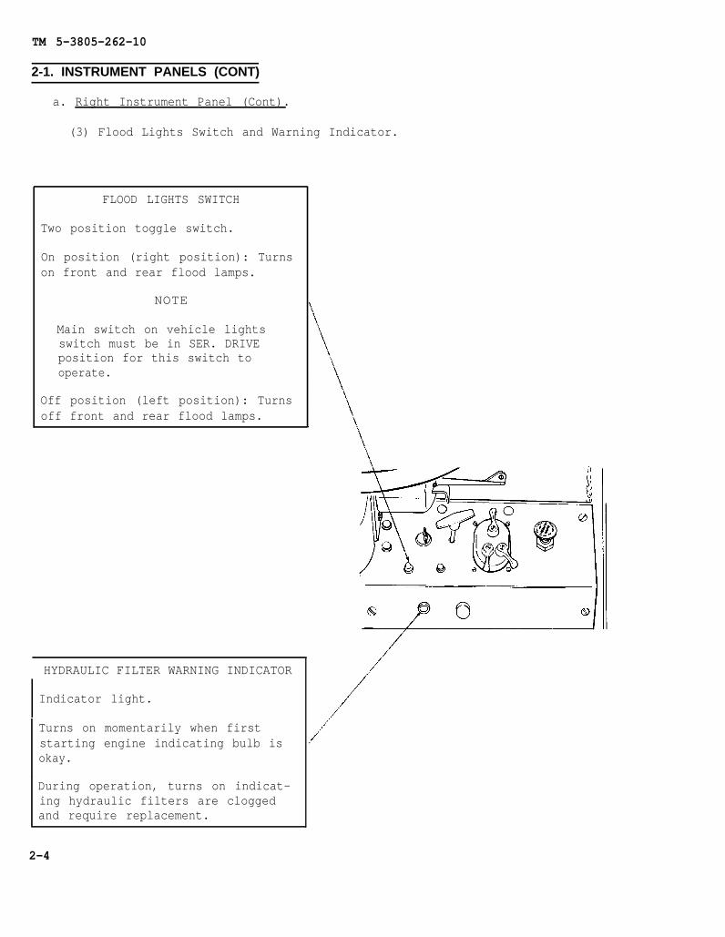
(3) Flood Lights Switch and Warning Indicator.
FLOOD LIGHTS SWITCH
Two position toggle switch.
On position (right position): Turnson front and rear flood lamps.
NOTE
Main switch on vehicle lightsswitch must be in SER. DRIVEposition for this switch tooperate.
Off position (left position): Turnsoff front and rear flood lamps.
HYDRAULIC FILTER WARNING INDICATOR
Indicator light.
Turns on momentarily when firststarting engine indicating bulb isokay.
During operation, turns on indicat-ing hydraulic filters are cloggedand require replacement.
2-4

TM 5-3805-262-10
2-1. INSTRUMENT PANELS (CONT)
a. Right Instrument Panel (Cont).
(4) Vehicle Lights Switch.
MAIN SWITCHFive position switch section.
B.O. MARKER: Black out tail lights lit. Stoplights will light when brake treadle valve is pressed.
B.O. DRIVE: Black out tail lights and blackout drivinglamp lit. Stop lights will lightwhenbraketreadle valve is pressed.
OFF (Unmarked): All lamps off.
STOP LIGHT Stop lights will light when brake treadle valve is depressed. Turn signals can beturned on.
SER DRIVE: Tail lights and front driving lamps lit. Stop lights will light when brake treadle valve ispressed. Turn signals and flood lights can be turned on.
NOTEIgnition key switch must be in extreme counterclockwise position or on position for vehicle lightsswitch to operate.
AUXILIARY SWITCH
Four position switch section.
PANEL BRT.: Gage lights brightly litand cab dome light can be turned on.
DIM: Gage lights dimly lit and cabdome light can be turned on.
OFF (unmarked): Panel and taillights off.
PARK: Service tail lights lit (mainswitch in SER DRIVE position) andgage lights dimly lit and cab domelight can be turned on. Black outtail lights lit (main switch in B.O.DRIVE or B.O. MARKER position).
NOTE
Main switch section must be inany position other than OFF forauxiliary switch section tooperate.
MECHANICAL LOCK
Spring loaded switch section.
LOCK (unmarked): Main switch can on-ly be placed in B.O. MARKER posi-tion; all other positions lockedout.
UNLOCKED: Enables main switch to beplaced in B.O. DRIVE, STOP LIGHT, orSER DRIVE POSITION.
To operate, hold lever in UNLOCK po-sition and move main switch lever todesired position.
2-5

TM 5-3805-262-10
2-1. INSTRUMENT PANELS (CONT)
a. Right Instrument Panel (Cont).
(5) Other Controls and Indicator.
SHUT OFF CONTROL
Fuel shut off control; engine stop.
Cable connected to fuel injectionpump fuel shut off lever.
Pull out to stop engine. After en-gine has stopped, push control in.Control must be pushed in all theway in order to start engine.
PARKING BRAKE CONTROL
Pull on, push off control.
Applies parking brake.
Pulling knob out applies parkingbrake. Pushing knob in releasesparking brake. When parking brakeapplied, BRAKE ENGAGED and CLUTCHPRESS warning indicators on left in-strument panel will be lit.
DIMMER COMPT LIGHTS CONTROL
Rheostat control.
Controls brightness of gage lightsand cab dome light (auxiliary switchin any position other than OFF).Turn control to extreme counter-clockwise position for brightly litlights. Turn control clockwise todecrease brightness. Extreme clock-wise position turns lights off.
AIR PRESSURE WARNING ALARM
Audible alarm.
Sounds when engine is first starteduntil air pressure reaches approxi-mately 65 psi at which time it willturn off. During operation, soundsto warn operator that there is notenough air pressure to continue op-erating loader safely.
2-6

TM 5-3805-262-10
2-1. INSTRUMENT PANELS (CONT)
b. Left Instrument Panel.
(1) Warning Indicators.
BRAKE ENGAGED
Warning indicator light.
Turns on indicating there is low orno air pressure in brake system.Will also turn on when parking brakecontrol is pulled out indicatingparking brake is applied.
OIL PRESS
Warning indicator light.
Turns on indicating there is no oilpressure or low oil pressure in theengine. Will also turn on if engineis stopped and ignition key switchis turned to on position indicatingbulb is okay. If this indicatorturns on when engine is running,turn engine off and check engine oillevel. If engine oil level is okay,do not start engine; notify organi-zational level maintenance.
AUXILIARY STEERING
Audible warning indicator and light.
Buzzer sounds and lamp turns on in-dicating steering system is notoperating and that auxiliary steer-ing system is operating. If buzzersounds and/or lamp turns on, stoploader immediately and notify organ-izational maintenance.
NOTE
The auxiliary steering systemis only used for a short periodof time if steering systemdoesn’t operate. When actuated,this system will allow you tosteer the loader with hydraulicpower until the loader can bestopped. After stopping loader,be sure you turn ignition keyswitch to off position andapply parking brake as soon aspossible. If you fail to dothis, you will cause damage toauxiliary steering electricmotor and discharge the batter-ies.
CLUTCH PRESS
Warning indicator light.
Turns on indicating there is no oilpressure or low oil pressure in thetransmission torque converter. Willalso turn on if engine is stoppedand ignition key switch is turned toon position indicating bulb is okay,if engine is running and declutchtreadle valve is pressed, and ifparking brake is applied. If thisindicator turns on with enginerunning and declutch treadle valveis not depressed, and stays on formore than 60 seconds, stop engineand notify organizational mainte-nance.
2-7
TM 5-3805-262-10
2-1. INSTRUMENT PANELS (CONT)
b. Left Instrument Panel.
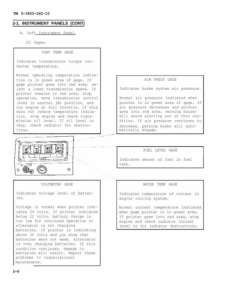
(2) Gages.
CONV TEMP GAGE
Indicates transmission torque con-verter temperature.
Normal operating temperature indica-tion is in green area of gage. Ifgage pointer goes into red area, se-lect a lower transmission speed. Ifpointer remains in red area, stopoperation, move transmission controllever in neutral (N) position, andrun engine at full throttle. If thisdoes not reduce temperature indica-tion, stop engine and check trans-mission oil level. If oil level isokay, check radiator for obstruc-tions.
VOLTMETER GAGE
Indicates voltage level of batter-ies.
Voltage is normal when pointer indi-cates 24 volts. If pointer indicatesbelow 22 volts, battery charge istoo low for continued operation oralternator is not chargingbatteries. If pointer is indicatingabove 30 volts and you know thatbatteries were not weak, alternatoris over charging batteries. If thiscondition continues, damage tobatteries will result. Report theseproblems to organizationalmaintenance.
AIR PRESS GAGE
Indicates brake system air pressure.
Normal air pressure indicated whenpointer is in green area of gage. Ifair pressure decreases and pointergoes into red area, warning buzzerwill sound alerting you of this con-dition. If air pressure continues todecrease, parking brake will auto-matically engage.
FUEL LEVEL GAGE
Indicates amount of fuel in fueltank.
WATER TEMP GAGE
Indicates temperature of coolant inengine cooling system.
Normal coolant temperature indicatedwhen gage pointer is in green area.If pointer goes into red area, stopengine and check radiator coolantlevel or for radiator obstructions.
2-8
TM 5-3805-262-10
2-1. INSTRUMENT PANELS (CONT)
b. Left Instrument Panel.
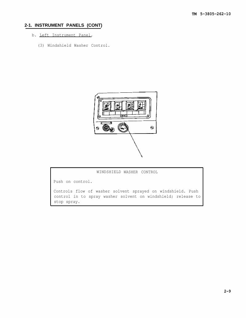
(3) Windshield Washer Control.
WINDSHIELD
Push on control.
WASHER CONTROL
Controls flow of washer solvent sprayed on windshield. Pushcontrol in to spray washer solvent on windshield; release tostop spray.
2-9

TM 5-3805-262-10
2-2. CONSOLE SWITCH PANEL
a. Switches and Control.
DEFROSTER SWITCH
Two position rotaryswitch.
ON: Turns on defrostermotor located abovefront windshield to de-fog front windshield.
OFF: Turns off defrostermotor.
HEATER FAN SWITCH
Three position pull on - push off switch.
OUT - LOW (switch shaft pulled completely out):Heater fan operates at low speed. Heater fandraws air over heater core where it is heatedthen expelled out heater console.
MID - HI (switch shaft pulled out to first de-tent position): Heater fan operates at highspeed.
IN - OFF (switch shaft pushed in): Heater fanoff.
FRONT WIPER SWITCH
Three position rotaryswitch.
H (high): Front wind-shield wiper motor oper-ates at high speed.
L (low): Front wind-shield wiper motor oper-ates at low speed.
OFF: Front windshieldwiper motor off.
HEAT CONTROL
Rotary control. Clockwise rotation increase; counterclock-wise rotation decrease.
Controls flow of engine cooling system coolant through heat-er core. For maximum heat, turn control completely clockwiseto WARM position. To turn off heat, turn control to OFFposition.
WARM: Valve completely open allowing maximum flow of enginecoolant through heater core.
OFF: Valve closed; flow of engine coolant through heatercore blocked.
2-10
TM 5-3805-262-10
2-2. CONSOLE SWITCH PANEL (CONT)
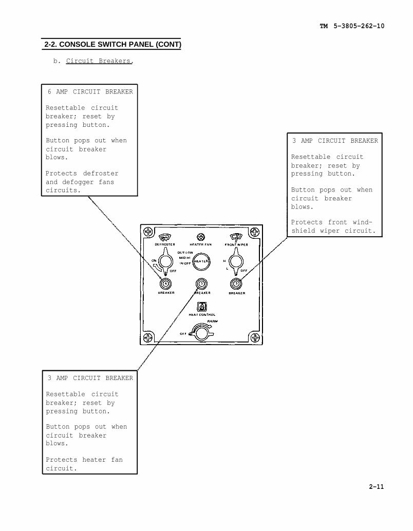
b. Circuit Breakers.
6 AMP CIRCUIT BREAKER
Resettable circuitbreaker; reset bypressing button.
Button pops out whencircuit breakerblows.
Protects defrosterand defogger fanscircuits.
3 AMP CIRCUIT BREAKER
Resettable circuitbreaker; reset bypressing button.
Button pops out whencircuit breakerblows.
Protects heater fancircuit.
3 AMP CIRCUIT BREAKER
Resettable circuitbreaker; reset bypressing button.
Button pops out whencircuit breakerblows.
Protects front wind-shield wiper circuit.
2-11

TM 5-3805-262-10
2-3. TRANSMISSION CONTROLS
TRANSMISSION CONTROL LEVER
Selects direction and drive speeds (in forward).
Rearmost position is reverse (R), next positionis neutral (N), third position is low range for-ward (F), and forwardmost position is high rangeforward (H). To go from low range forward (F) tohigh range forward (H), you must lift controllever up then push it forward. When controllever is in reverse (R) position, back-up alarmat rear of loader will sound.
Control lever must be in neutral (N) to startengine.
DECLUTCH TREADLE VALVE
Neutralizes transmission, applies service brakesand turns on stop lights and CLUTCH PRESS war-ning indicator.
Use to provide maximum engine power to increaseloader hydraulic system power for raising buck-et. Move loader into stockpile. When enginespeed decreases, press declutch treadle valve todisengage transmission, then press acceleratorpedal to increase engine rpm providing maximumengine power to loader hydraulic system toquickly raise bucket.
2-12
TM 5-3805-262-10
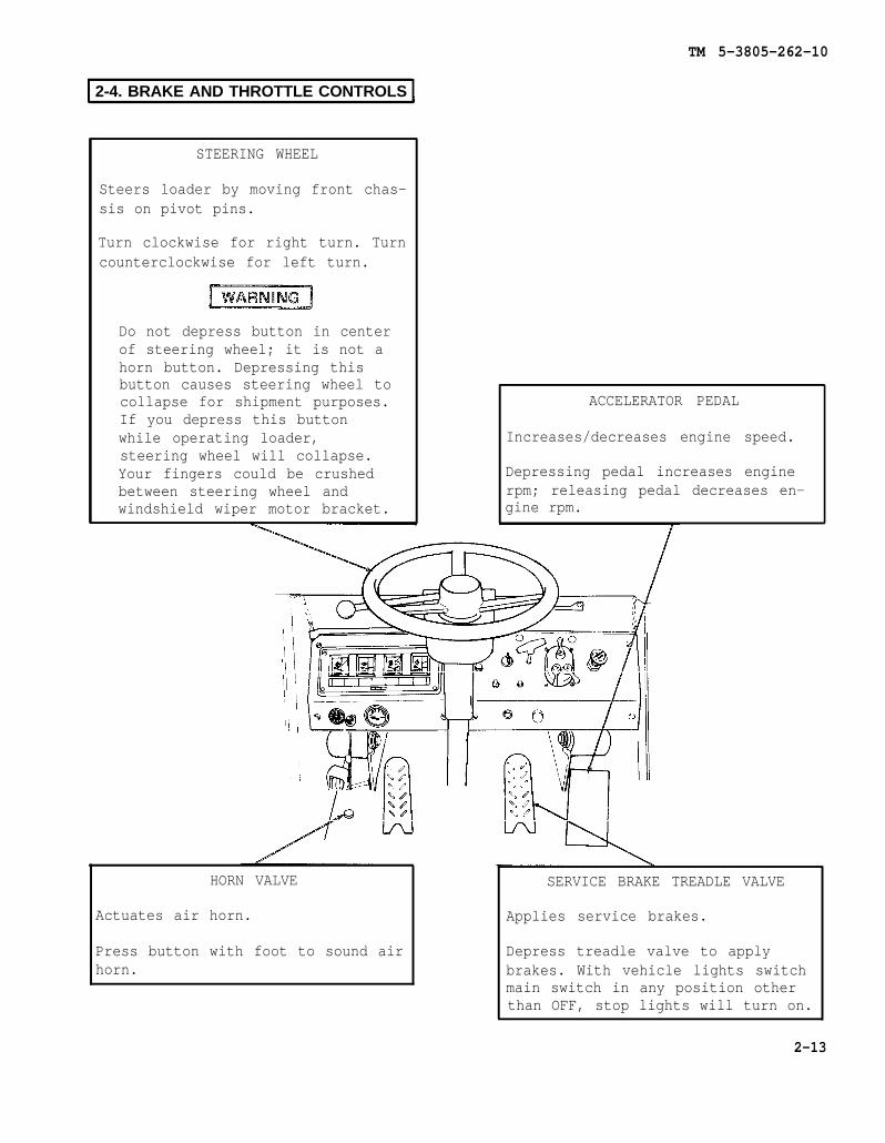
2-4. BRAKE AND THROTTLE CONTROLS
STEERING WHEEL
Steers loader by moving front chas-sis on pivot pins.
Turn clockwise for right turn. Turncounterclockwise for left turn.
Do not depress button in centerof steering wheel; it is not ahorn button. Depressing thisbutton causes steering wheel tocollapse for shipment purposes.If you depress this buttonwhile operating loader,steering wheel will collapse.Your fingers could be crushedbetween steering wheel andwindshield wiper motor bracket.
ACCELERATOR PEDAL
Increases/decreases engine speed.
Depressing pedal increases enginerpm; releasing pedal decreases en-gine rpm.
HORN VALVE
Actuates air horn.
Press button with foot to sound airhorn.
SERVICE BRAKE TREADLE VALVE
Applies service brakes.
Depress treadle valve to applybrakes. With vehicle lights switchmain switch in any position otherthan OFF, stop lights will turn on.
2-13

TM 5-3805-262-10
2-5. TURN SIG NALS AND FLASHER
TURN SIGNAL SWITCH
Three position switch with indicator.
Lever in forward position (away from you): Lamp assembly mounted at topleft of cab flashes on and off signaling left turn. Bulb located inturn signal switch will also flash on and off. You must return lever tocenter position after you have completed the turn to stop lamp assemblyfrom flashing.
Lever in center position: Turn signals off.
Lever in rearward position (toward you): Lamp assembly mounted at topright of cab flashes on and off signaling right turn. Bulb located inturn signal switch will also flash on and off. You must return lever tocenter position after you have completed the turn to stop lamp assemblyfrom flashing.
HAZARD CONTROL
Pull on control.
On (pull out): Pull control out to the right. Lamp assem-blies mounted at top left and right of cab will flash on andoff. Bulb located in turn signal switch will also flash onand off.
Off: Turn off flashing lamp assemblies by pulling turnsignal switch lever down or up.
2-14

TM 5-3805-262-10
2-6. REAR WINDSHIELD DEFOGGER FANS
ON-OFF SWITCH
Three position rocker switch.
LOW: Fan motor operates at lowspeed.
OFF: Turns off power to fan motor.
HIGH: Fan motor operates at highspeed.
To adjust position of defogger fans,grasp motor with your hands andfirmly move into desired position.
Before adjusting position ofdefogger fan, be sure it is notoperating. Failure to do socould cause serious injury tofingers or hand by rotating fanblade. If you injure your fin-gers or hand, obtain medicalaid immediately.
2-15
TM 5-3805-262-10
2-7. DOME LIGHT SWITCH]
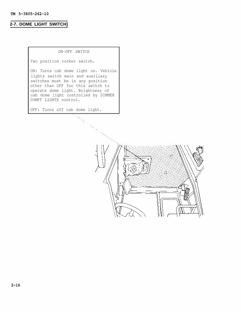
ON-OFF SWITCH
Two position rocker switch.
ON: Turns cab dome light on. Vehiclelights switch main and auxiliaryswitches must be in any positionother than OFF for this switch tooperate dome light. Brightness ofcab dome light controlled by DIMMERCOMPT LIGHTS control.
OFF: Turns off cab dome light.
2-16

TM 5-3805-262-10
2-8. UPPER AND LOWER DOOR LATCHES
Releases upper door enabling it to be swung open.
When upper door is opened, be sure you latch it to sideof cab. Failure to do so will allow door to swing backand forth causing glass to break and injuring you.
Move latch handle towards rear of cab to release latch. Whenupper door is released and opened, you must latch it to sideof cab to prevent injury to yourself and damaging it.
DOOR LATCH
Latches door in closed position.
TO open latch, push latch handledown until latch clears door strik-er, swing door open, then releaselatch handle.
To latch door, push latch handledown, gently but firmly close door,and release handle. Check that latchengages door striker.
CAB LATCH
Latches upper door in open position.
To latch upper door to side of cab,release upper door latch. Swing up-per door open all the way. Move cablatch handle towards front of loaderand gently but firmly push upperdoor against side of cab and movecab latch handle to engage bracketon exterior of upper door.
Move latch handle towards front ofloader to release upper door.
2-17
TM 5-3805-262-10
2-9. OPERATOR’S SEAT
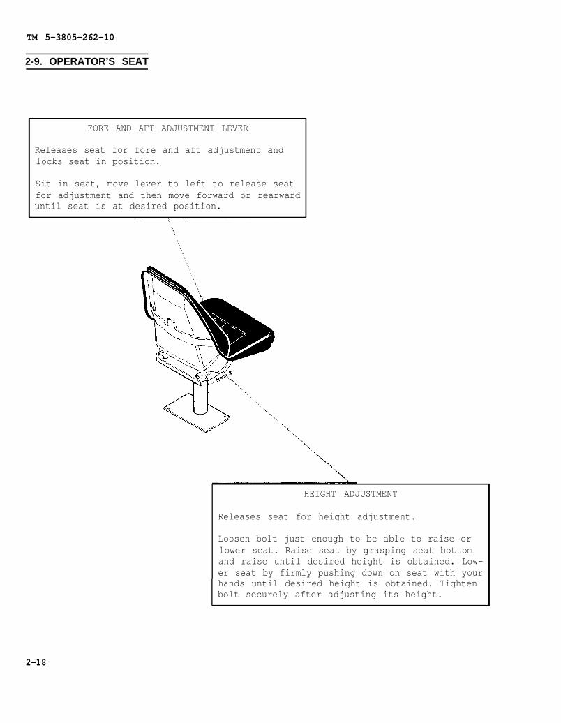
FORE AND AFT ADJUSTMENT LEVER
Releases seat for fore and aft adjustment andlocks seat in position.
Sit in seat, move lever to left to release seatfor adjustment and then move forward or rearwarduntil seat is at desired position.
HEIGHT ADJUSTMENT
Releases seat for height adjustment.
Loosen bolt just enough to be able to raise orlower seat. Raise seat by grasping seat bottomand raise until desired height is obtained. Low-er seat by firmly pushing down on seat with yourhands until desired height is obtained. Tightenbolt securely after adjusting its height.
2-18

TM 5-3805-262-10
2-10. LOADER CONTROLS
LIFT ARM CONTROL LEVER
Four position control lever. Con-trols flow of hydraulic oil to liftcylinder assemblies.
FLOAT: Bucket follows contour ofground. Used only when bucket is onground and you want it to follow theshape of the ground. It causes oilto flow between ends of lift cylin-der assemblies only.
LOWER: Lowers bucket as long as con-trol lever is in this position.
NEUT.: Bucket held in position.
RAISE: Raises bucket to desiredheight until returned to NEUT. oruntil height selected by bucketheight control is reached.
BUCKET CONTROL LEVER
Three position control lever. Con-trols bucket position for dumping orcarrying a load.
DUMP: Bucket will be quickly posi-tioned to dump a load.
NEUT.: Bucket held in position.
CROWD: Bucket rolls back until con-trol lever returned to NEUT. posi-tion. Use to position bucket forcarrying a load.
CLAM CONTROL LEVER
Three position control lever. Con-trols clam opening or closing.
OPEN: Opens clam until control leverplaced in HOLD position or clamopened to maximum position.
HOLD: Holds clam in position.
CLOSE: Closes clam until control le-ver placed in HOLD position or clamcompletely closed.
2-19
TM 5-3805-262-10
2-10. LOADER CONTROLS (CONT)
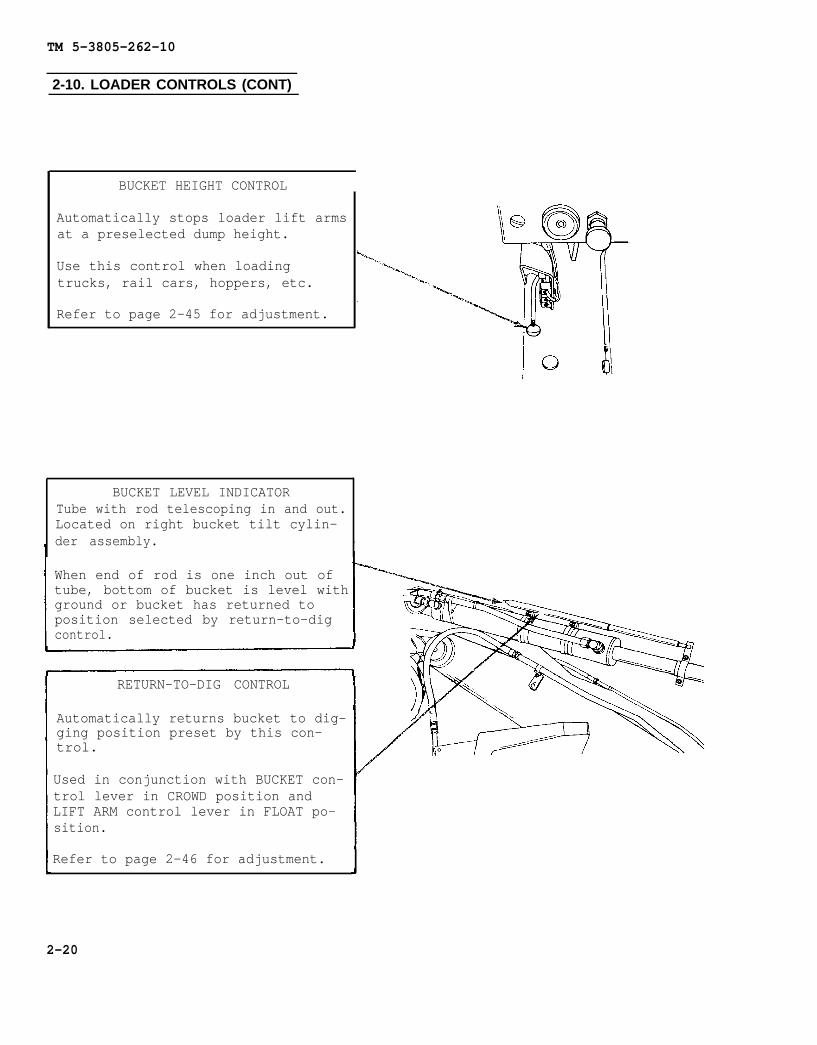
BUCKET HEIGHT CONTROL
Automatically stops loader lift armsat a preselected dump height.
Use this control when loadingtrucks, rail cars, hoppers, etc.
Refer to page 2-45 for adjustment.
BUCKET LEVEL INDICATORTube with rod telescoping in and out.Located on right bucket tilt cylin-der assembly.
When end of rod is one inch out oftube, bottom of bucket is level withground or bucket has returned toposition selected by return-to-digcontrol.
RETURN-TO-DIG CONTROL
Automatically returns bucket to dig-ging position preset by this con-trol.
Used in conjunction with BUCKET con-trol lever in CROWD position andLIFT ARM control lever in FLOAT po-sition.
Refer to page 2-46 for adjustment.
2-20
TM 5-3805-262-10
2-10. LOADER CONTROLS (CONT)
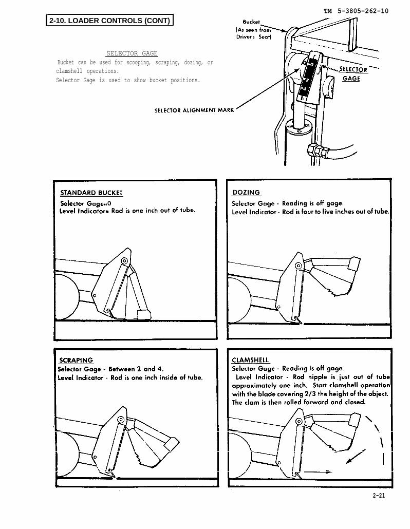
SELECTOR GAGEBucket can be used for scooping, scraping, dozing, orclamshell operations.Selector Gage is used to show bucket positions.
2-21

TM 5-3805-262-10
2-11. EXTERNALLY MOUNTED CONTROLS AND INDICATORS
HOURMETER/TACHOMETER
Connected to engine tachometerdrive.
HOURMETER: Indicates cumulativenumber of engine operating hours.Connected to engine tachometer driveand operates only when engine is op-erating. Records up to 9999.9 hours.
TACHOMETER: Indicates engine speedin revolutions per minute (rpm).Each short mark on gage equals 50rpm; each long mark equals 100 rpm.
AIR CLEANER RESTRICTION INDICATOR
Indicates air cleaner filter ele-ments require servicing.
Factory set to signal when aircleaner filter elements require ser-vicing. Red signal indicator insideindicator gradually rises as airflow decreases due to dirt particlestrapped in elements. When red signalis fully exposed, it is locked inposition. After servicing filterelements, indicator is reset bypressing top of indicator.
SLAVE RECEPTACLE
Permits charging of batteries orslave starting of engine from an ex-ternal power source. Also provides apower source for charging/slavingother equipment.
+24 volts negative ground availableat this receptacle.
2-22

TM 5-3805-262-10
2-12. OTHER OPERATOR’S CONTROLS AND INDICATORS
TRANSMISSION OIL LEVEL DIPSTICK AND FILL
Indicates transmission oil level.
Oil level shall be between FULL andADD marks with CONV TEMP gage indi-cating in green zone and engine op-erating at idle speed.
Unlock dipstick, turn handle coun-terclockwise several turns, thenpull up to remove. Be sure dipstickis fully seated when reinstallingit, turn handle clockwise to tight-en, then lock it.
ENGINE OIL LEVEL DIPSTICK AND FILL
Indicates engine oil level.
Oil level shall be between ADD andFULL marks on dipstick.
Turn handle on dipstick counter-clockwise several turns, then pullup to remove. Install dipstick andturn handle clockwise to tighten.
2-23

TM 5-3805-262-10
2-12. OTHER OPERATOR’S CONTROLS AND INDICATORS (CONT)
HYDRAULIC RESERVOIR FILL
Located behind front access door.
Hydraulic reservoir ispressurized. Shut off enginebefore removing hydraulicreservoir fill cap. Failure todo so could cause serious in-jury or death.
With engine off , unlock and openfront access door. Use clean clothto clean area around fill cap. Re-move fill cap and add hydraulic oiluntil oil level can be seen in sightgage window. Reinstall fill cap andtighten securely by hand.
HYDRAULIC RESERVOIR OIL LEVEL SIGHT GAGE
Indicates hydraulic system oil lev-el.
Oil level shall be seen in sightgage with engine off, loader parkedon level surface, and bucket loweredto ground.
2-24

TM 5-3805-262-10
2-12. OTHER OPERATOR’S CONTROLS AND INDICATORS (CONT)
Located atwater from
AIR RESERVOIR DRAIN VALVE
right rear side of loader. Enables draining ofair reservoir.
With engine off, slowly open drain valve and drain waterfrom air reservoir. Tighten drain valve securely after allwater is drained.
2-25
TM 5-3805-262-10
Section II. PREVENTIVE MAINTENANCE CHECKS AND SERVICES (PMCS)
ParaGeneral . . . . . . . . . . . . . . . . . . . . . . . . . . . . . . . . . . . . . . . . . 2-13Preventive Maintenance Checks and Services . . . . . . . . . . . . . . . . . . . 2-14
2-13. GENERAL
Every mission begins and ends with the paperwork. There isn’t much of it, but youhave to keep it up. The forms and records you fill out have several uses. They are apermanent record of the services, repairs, and modifications made on your loader.They are reports to organizational maintenance and to your Commander. And they are achecklist for you when you want to know what is wrong with the loader after its lastuse, and whether those faults have been fixed. For the information you need on formsand records, see DA PAM 738-750.
2-14. PREVENTIVE MAINTENANCE CHECKS AND SERVICES
a. The item numbers of table 2-1 indicate the sequence the PMCS are to be per-formed. This column should be used as the source of item numbers for the TM Numbercolumn on DA Form 2404, Equipment Inspection and Maintenance Worksheet, in recordingresults of PMCS.
b. BEFORE - Checks and services performed prior to the equipment leaving itscontainment area or performing its intended mission.
c. DURING - Checks begin when the equipment is being used in its intendedmission.
d. AFTER - Checks and services begin when the equipment is taken out of itsmission mode or returned to its containment area.
e. Do your weekly (W) PREVENTIVE MAINTENANCE weekly.
f. Do your monthly (M) PREVENTIVE MAINTENANCE once a month.
g. If something doesn’t work, troubleshoot it with the instructions in this man-
ual or notify your supervisor.
h. Always do your PREVENTIVE MAINTENANCE in the same order, so it gets to be ahabit. Once you’ve had some practice, you’ll spot anything wrong in a hurry.
i. If anything looks wrong and you can’t fix it, write it on your DA Form 2404.If you find something seriously wrong, report it to organizational maintenance RIGHTNow.
j. When you do your PREVENTIVE MAINTENANCE take along the tools you need to makeall the checks. You always need a rag or two.
2-26

TM 5-3805-262-10
2-14. PREVENTIVE MAINTENANCE CHECKS AND SE RVICES(CONT)
Dry cleaning solvent P-D-680 used to clean parts is toxicand flammable. Wear protective goggles and gloves and useonly in a well ventilated area. Avoid contact with skin,eyes and clothes and don’t breathe vapors. Do not use nearopen flame or excessive heat and don’t smoke when using it.Failure to do so could cause serious injury. If you becomedizzy while using cleaning solvent, get fresh air and medi-cal attention immediately. If contact with skin or clothesis made, flush with large amounts of water. If contact witheyes is made, wash eyes with water and get medical aidimmediately.
Compressed air used for cleaning purpose will not exceed 30psi. Use only with effective chip guarding and personal pro-tective equipment (goggles/shield, gloves, etc). Failure todo so could cause serious injury to eyes and possible blind-ness. If you hurt your eyes or if a foreign object is blowninto your eyes, seek medical attention immediately.
(1) Keep it clean: Dirt, grease, oil, and debris only get in the way and maycover up a serious problem. Clean as you work and as needed. Use dry cleaning sol-vent (P-D-680) to clean metal surfaces. Use soap and water when you clean rubber orplastic material.
(2) Bolts, nuts, and screws: Check that they are not loose, missing, bent orbroken. You can-t try them all with a tool of course, but look for chipped paint,bare metal or rust around bolt heads. If you find one you think is loose, tightenit, or report it to organizational maintenance if you can-t tighten it.
(3) Welds: Look for loose or chipped paint, rust or gaps where parts are weldedtogether. If you find a bad weld , report it to organizational maintenance.
(4) Electric wires and connectors: Look for cracked or broken insulation, barewires and loose or broken connectors. Tighten loose connectors and make sure thatthe wires are in good shape.
(5) Hoses and fluid lines: Look for wear, damage and leaks. Make sure clampsand fittings are tight. Wet spots show leaks, of course, but a stain around a fit-ting or connector can mean a leak. If a leak comes from a loose fitting or connec-tor, tighten it. If something is broken or worn out, report it to organizationalmaintenance.
k. It is necessary for you to know how fluid leaks affect the status of your e-quipment. The following are definitions of the types/classes of leakage you need toknow to be able to determine the status of your equipment. Learn them and be famil-iar with them and REMEMBER - when in doubt, notify your supervisor.
2-27

TM 5-3805-262-10
2-14. PREVENTIVE MAINTENANCE CHECKS AND SERVICES (CONT)
Leakage definitions for Crew/Operator PMCS
Class I Seepage of fluid (as indicated by wetness or discoloration) notgreat enough to form drops.
Class II Leakage of fluid great enough to form drops, but not enough to causedrops to drip from the item being checked/inspected.
Class III Leakage of fluid great enough to form drops that fall from the itembeing checked/inspected.
Equipment operation is allowable with minor leakages (classI or II). Of course, consideration must be given to the flu-id capacity in the system/item being checked/inspected. Whenin doubt, notify your supervisor.
Class III leaks should be corrected immediately or reportedto your supervisor or organizational maintenance.
2-28
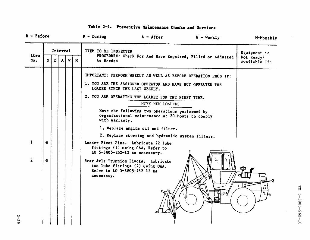
Table 2-1.
TM 5-3805-262-10
2-29
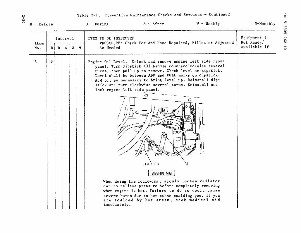
Table 2-1.
TM 5-3805-262-10
2-30

TM 5-3805-262-10
2-31

Table 2-1.
TM 5-3805-262-10
2-32

TM 5-3805-262-10
Change 1
2-33

TM
5
-38
05
-26
2-1
0
2-3
4C
han
ge 1

TM 5-3805-262-10
2-35
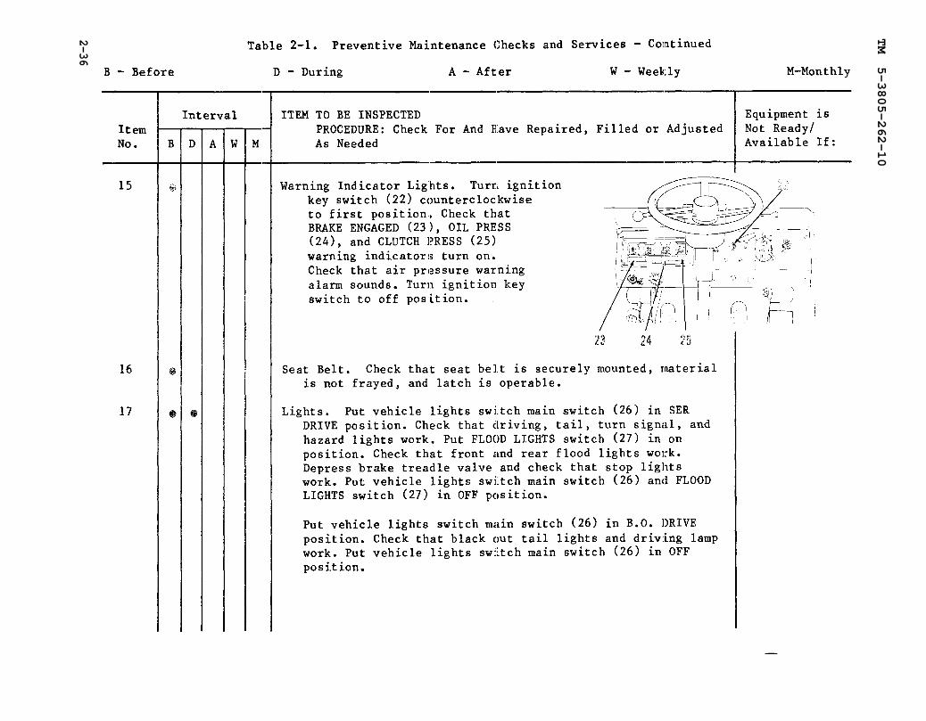
Table 2-1.
TM 5-3805-262-10
2-36

TM 5-3805-262-10
2-37

Table 2-1.
TM 5-3805-262-10
2-38
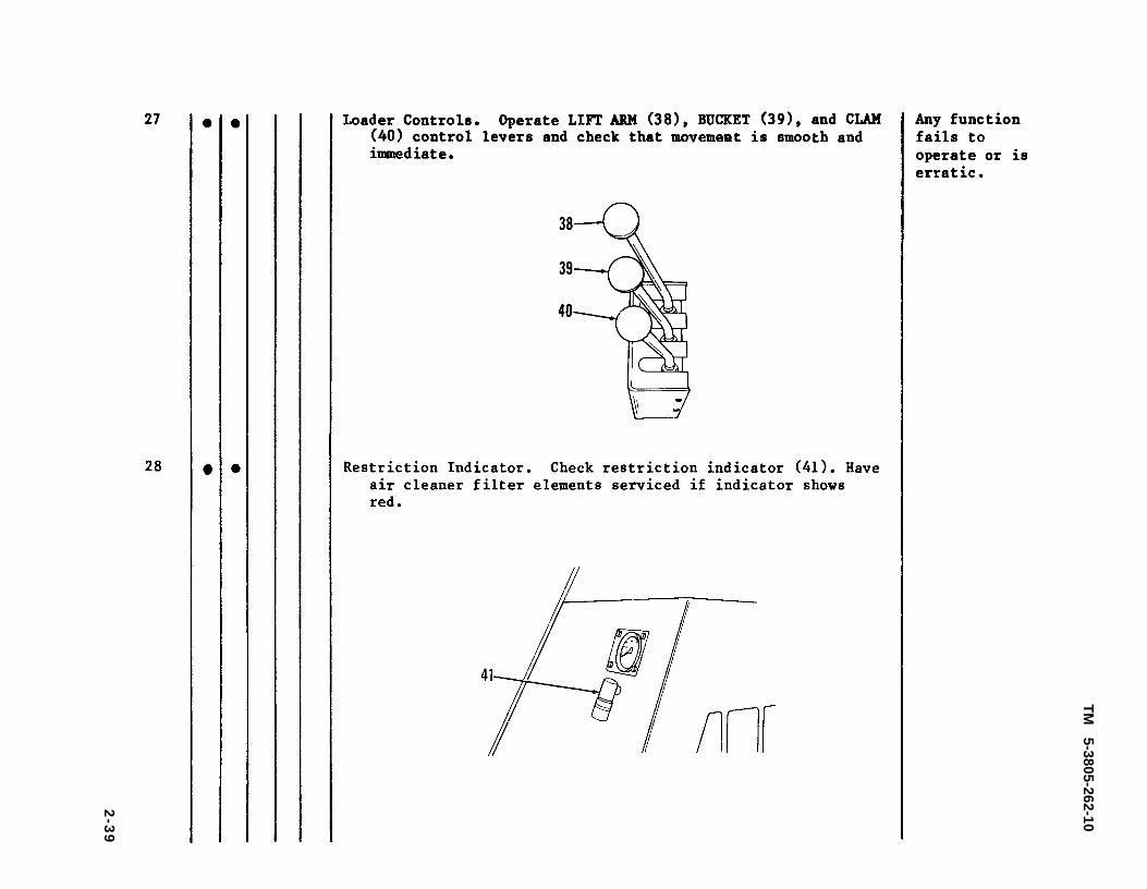
TM
5-3805-262-10
2-3
9
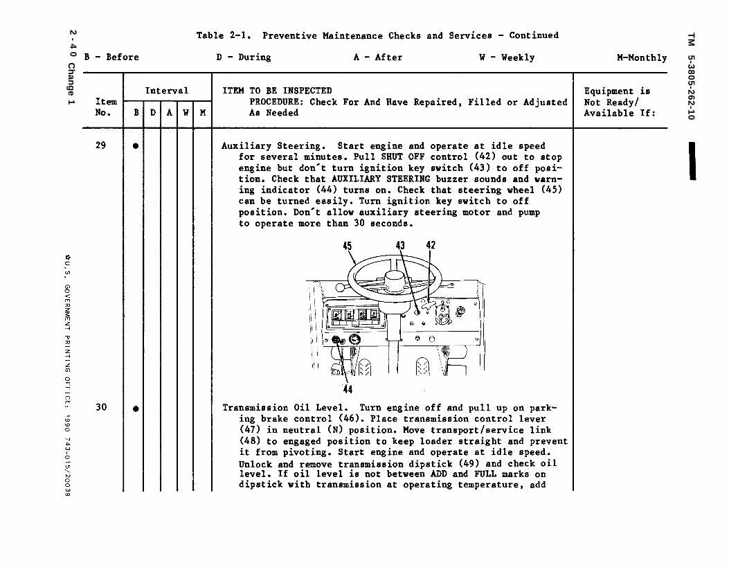
TM
5
-38
05
-26
2-1
0
2-
40
Ch
ang
e 1
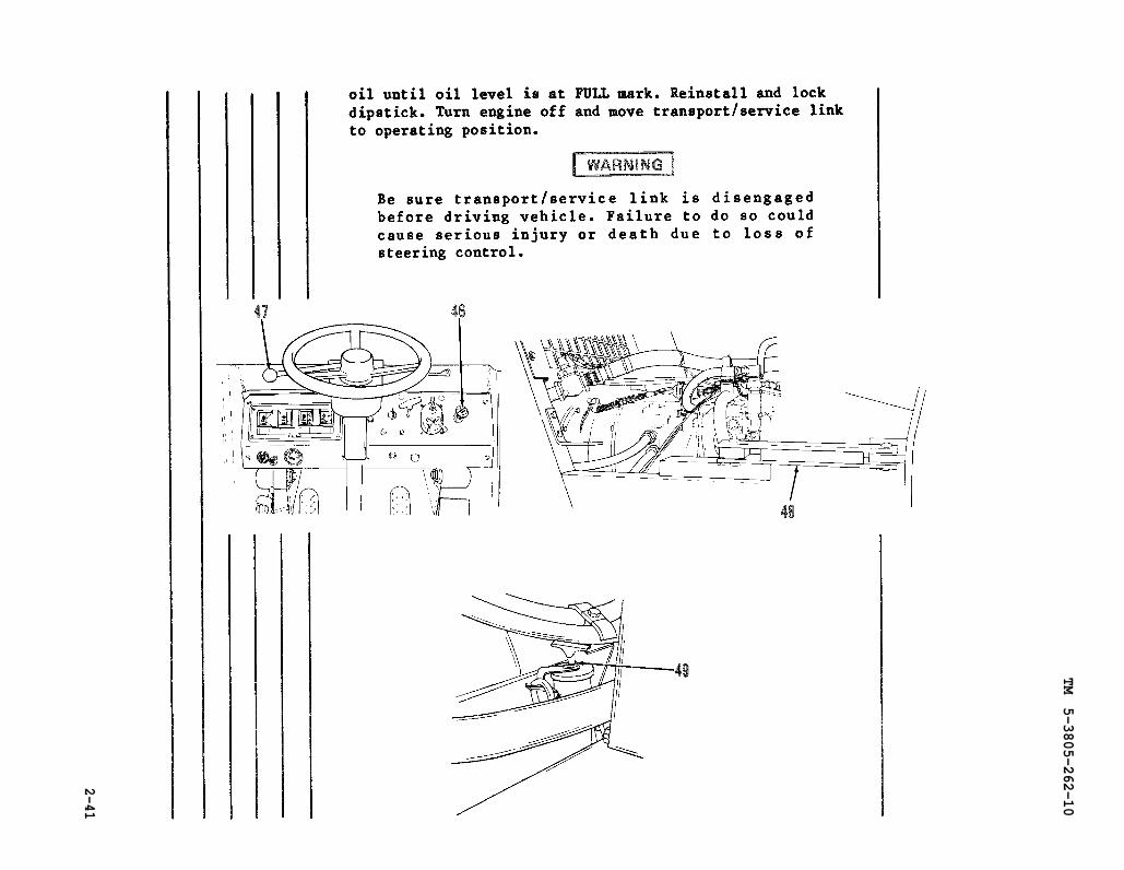
TM 5-3805-262-10
2-41
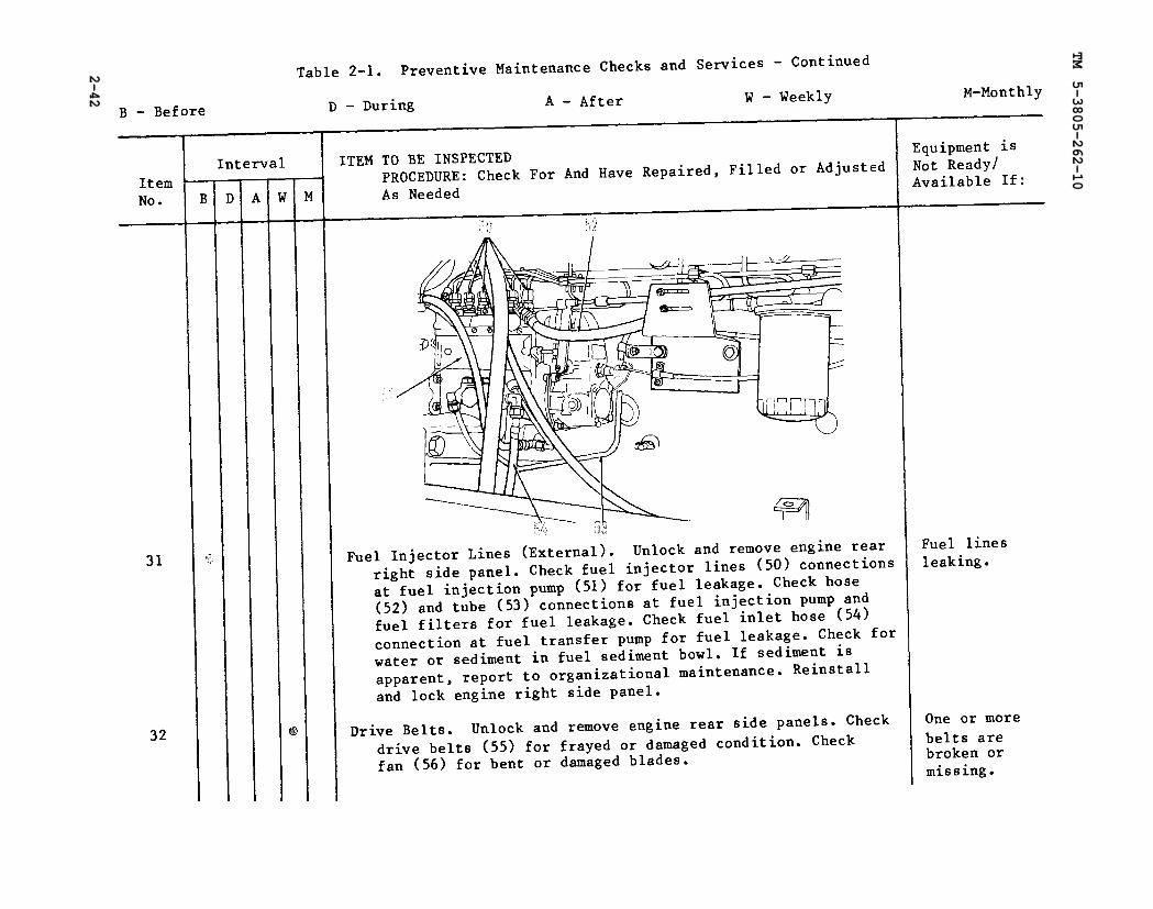
Table 2-1.
TM 5-3805-262-10
2-42
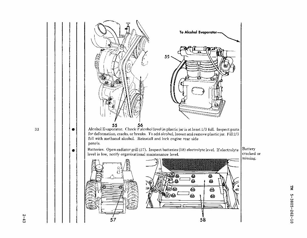
TM 5-3805-262-10
2-43

Table 2-1.
TM 5-3805-262-10
2-44
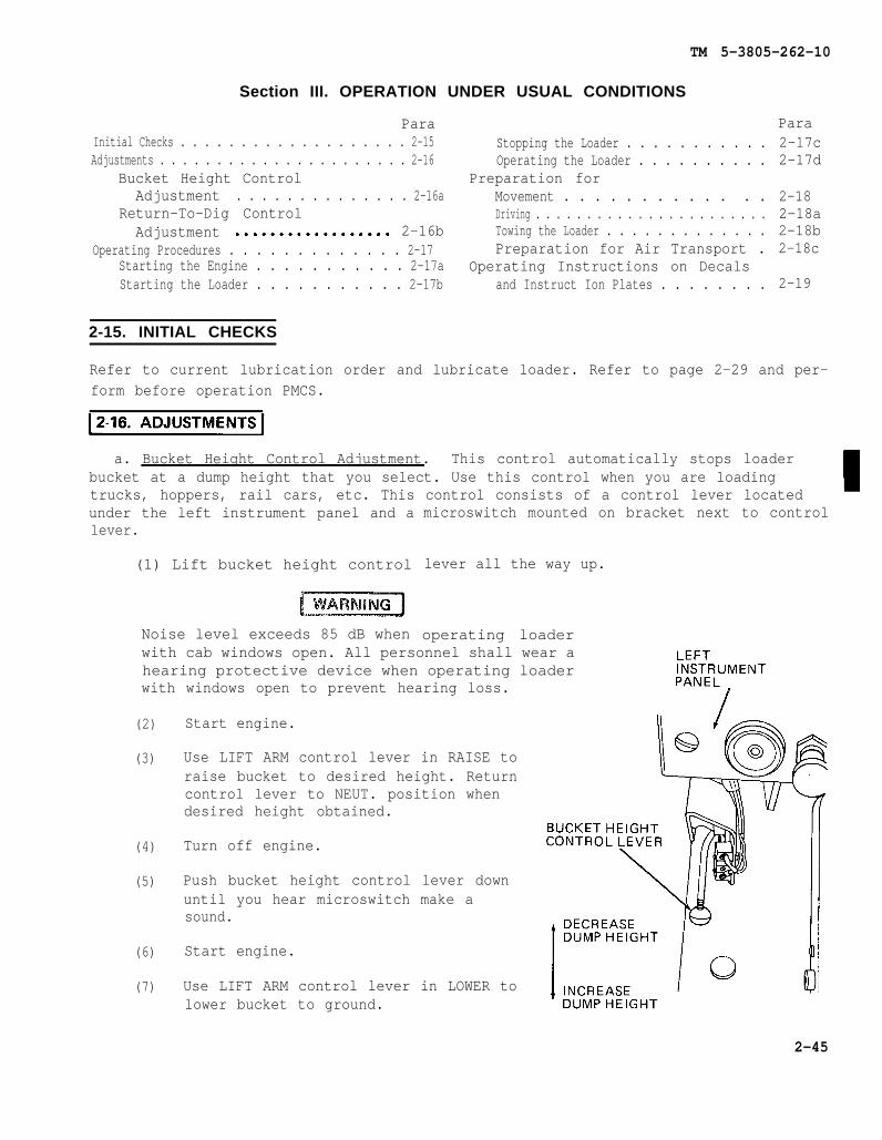
2-16.
TM 5-3805-262-10
Section III. OPERATION UNDER USUAL CONDITIONS
ParaInitial Checks . . . . . . . . . . . . . . . . . . . 2-15Adjustments . . . . . . . . . . . . . . . . . . . . . . 2-16
Bucket Height ControlAdjustment . . . . . . . . . . . . . . 2-16a
Return-To-Dig ControlAdjustment 2-16b
Operating Procedures . . . . . . . . . . . . . 2-17Starting the Engine . . . . . . . . . . . 2-17aStarting the Loader . . . . . . . . . . . 2-17b
2-15. INITIAL CHECKS
Stopping the Loader . . . . . . . . . . .Operating the Loader . . . . . . . . . .
Preparation forMovement . . . . . . . . . . . . .Driving . . . . . . . . . . . . . . . . . . . . . . .Towing the Loader . . . . . . . . . . . . .Preparation for Air Transport .
Operating Instructions on Decalsand Instruct Ion Plates . . . . . . . .
Para2-17c2-17d
2-182-18a2-18b2-18c
2-19
Refer to current lubrication order and lubricate loader. Refer to page 2-29 and per-form before operation PMCS.
a. Bucket Height Control Adjustment. This control automatically stops loaderbucket at a dump height that you select. Use this control when you are loadingtrucks, hoppers, rail cars, etc. This control consists of a control lever locatedunder the left instrument panel and alever.
(1) Lift bucket height control
microswitch mounted on bracket next to control
lever all the way up.
operating loaderNoise level exceeds 85 dB whenwith cab windows open. All personnel shall wear ahearing protective device when operating loaderwith windows open to prevent hearing loss.
(2)
(3)
(4)
(5)
(6)
(7)
Start engine.
Use LIFT ARM control lever in RAISE toraise bucket to desired height. Returncontrol lever to NEUT. position whendesired height obtained.
Turn off engine.
Push bucket height control lever downuntil you hear microswitch make asound.
Start engine.
Use LIFT ARM control lever in LOWER tolower bucket to ground.
2-45
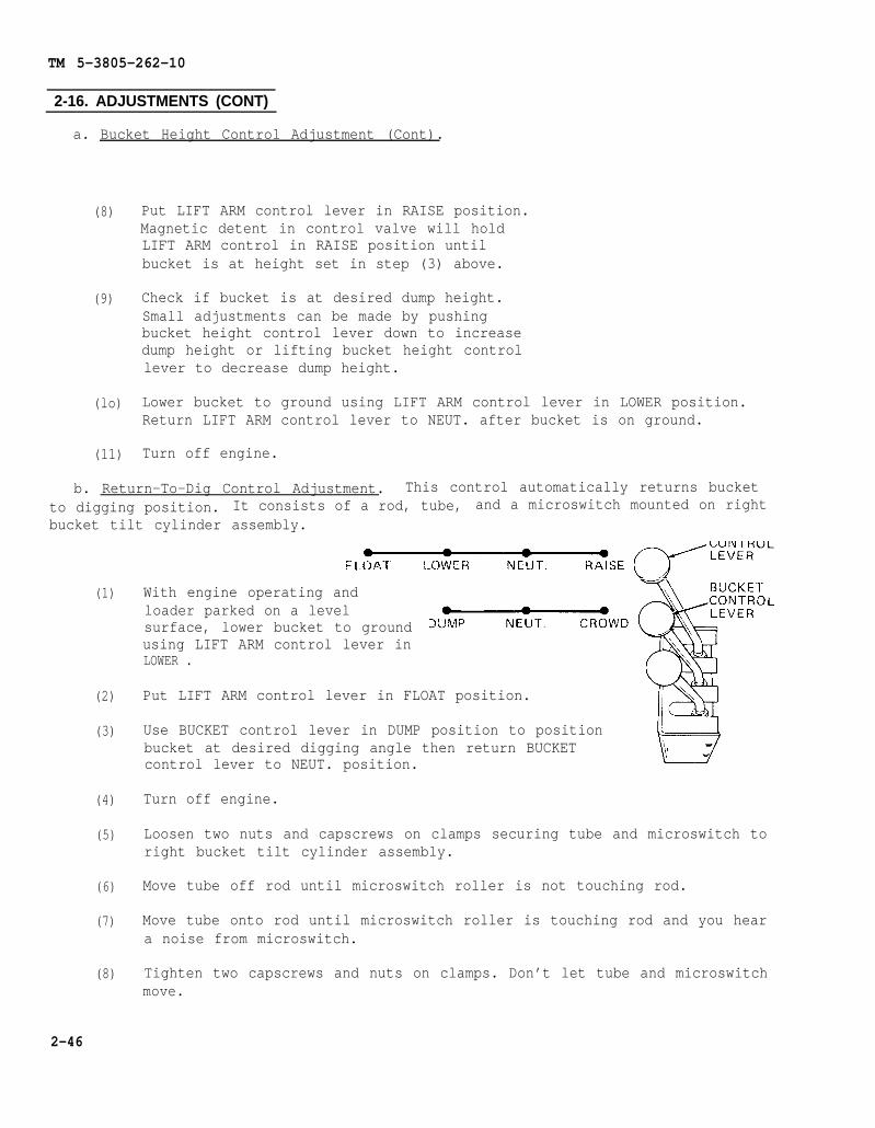
TM 5-3805-262-10
2-16. ADJUSTMENTS (CONT)
a. Bucket Height Control Adjustment (Cont).
(8)
(9)
(lo)
(11)
Put LIFT ARM control lever in RAISE position.Magnetic detent in control valve will holdLIFT ARM control in RAISE position untilbucket is at height set in step (3) above.
Check if bucket is at desired dump height.Small adjustments can be made by pushingbucket height control lever down to increasedump height or lifting bucket height controllever to decrease dump height.
Lower bucket to ground using LIFT ARM control lever in LOWER position.Return LIFT ARM control lever to NEUT. after bucket is on ground.
Turn off engine.
b. Return-To-Dig Control Adjustment. This control automatically returns bucketto digging position. It consists of a rod, tube, and a microswitch mounted on rightbucket tilt cylinder assembly.
(1)
(2)
(3)
(4)
(5)
(6)
(7)
(8)
With engine operating andloader parked on a levelsurface, lower bucket to groundusing LIFT ARM control lever inLOWER .
Put LIFT ARM control lever in FLOAT position.
Use BUCKET control lever in DUMP position to positionbucket at desired digging angle then return BUCKETcontrol lever to NEUT. position.
Turn off engine.
Loosen two nuts and capscrews on clamps securing tube and microswitch toright bucket tilt cylinder assembly.
Move tube off rod until microswitch roller is not touching rod.
Move tube onto rod until microswitch roller is touching rod and you heara noise from microswitch.
Tighten two capscrews and nuts on clamps. Don’t let tube and microswitchmove.
2-46
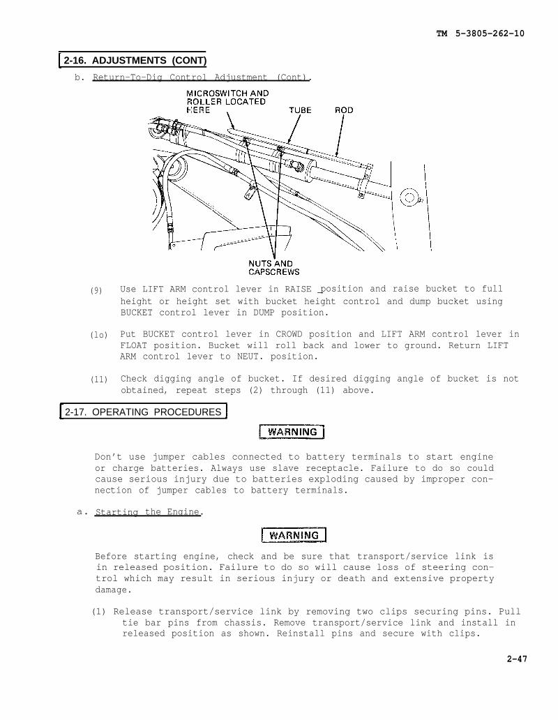
TM 5-3805-262-10
2-16. ADJUSTMENTS (CONT)
b. Return-To-Dig Control Adjustment (Cont).
(9)
(lo)
(11)
position and raise bucket to fullUse LIFT ARM control lever in RAISE _height or height set with bucket height control and dump bucket usingBUCKET control lever in DUMP position.
Put BUCKET control lever in CROWD position and LIFT ARM control lever inFLOAT position. Bucket will roll back and lower to ground. Return LIFTARM control lever to NEUT. position.
Check digging angle of bucket. If desired digging angle of bucket is notobtained, repeat steps (2) through (11) above.
2-17. OPERATING PROCEDURES
Don’t use jumper cables connected to battery terminals to start engineor charge batteries. Always use slave receptacle. Failure to do so couldcause serious injury due to batteries exploding caused by improper con-nection of jumper cables to battery terminals.
Starting the Engine.a.
Before starting engine, check and be sure that transport/service link isin released position. Failure to do so will cause loss of steering con-trol which may result in serious injury or death and extensive propertydamage.
(1) Release transport/service link by removing two clips securing pins. Pulltie bar pins from chassis. Remove transport/service link and install inreleased position as shown. Reinstall pins and secure with clips.
2-47

TM 5-3805-262-10
2-17. OPERATING PROCEDURES (CONT)
a. Starting the Engine (Cont).
Always use hand rails and steps when you mount or dismount loader. Don-tuse steering wheel or controls as a hand rail. Any other method ofmounting or dismounting loader could make you slip and fall causing ser-ious injury to yourself.
(2)
(3)
(4)
(5)
Mount loader and sit in operator’s seat.
If necessary, adjust height ofseat. If necessary to adjustfore and aft position of seat,move adjustment lever to leftto release seat then move seatforward or backward as neces-sary.
Close both cab doors.
Fasten your seat belt.
2-48

TM 5-3805-262-10
2-17. OPERATING PROCEDURES (CONT)
a. Starting the Engine (Cont).
(6) Pull up on parking brake control to apply parking brake.
(7) Check and ensuretions.
that hydraulic control levers are in NEUT. or HOLD posi-
(8) Check and ensure that SHUT OFF control is pushed completely in.
(9) Place transmission control lever in neutral (N) position.
Before starting engine, fasten your seat belt securely and be sure park-ing brake is applied, transmission control lever is in neutral (N) posi-tion, and both cab doors are closed. Failure to do so could cause seri-ous injury or death due to an accident.
(10) Insert key into ignition key switch. Turn key to first position clockwise(on position). Note that warning indicators (BRAKE ENGAGED, OIL PRESS,and CLUTCH PRESS) turn on and air pressure warning alarm sounds.
(11) Push accelerator pedal down approximately one to two inches.
2-49
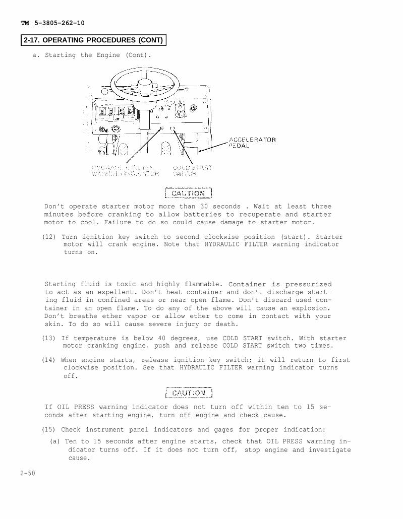
TM 5-3805-262-10
2-17. OPERATING PROCEDURES (CONT)
a. Starting the Engine (Cont).
Don’t operate starter motor more than 30 seconds . Wait at least threeminutes before cranking to allow batteries to recuperate and startermotor to cool. Failure to do so could cause damage to starter motor.
(12) Turn ignition key switch to second clockwise position (start). Startermotor will crank engine. Note that HYDRAULIC FILTER warning indicatorturns on.
Starting fluid is toxic and highly flammable. Container is pressurizedto act as an expellent. Don’t heat container and don’t discharge start-ing fluid in confined areas or near open flame. Don’t discard used con-tainer in an open flame. To do any of the above will cause an explosion.Don’t breathe ether vapor or allow ether to come in contact with yourskin. To do so will cause severe injury or death.
(13) If temperature is below 40 degrees, use COLD START switch. With startermotor cranking engine, push and release COLD START switch two times.
(14) When engine starts, release ignition key switch; it will return to firstclockwise position. See that HYDRAULIC FILTER warning indicator turnsoff.
If OIL PRESS warning indicator does not turn off within ten to 15 se-conds after starting engine, turn off engine and check cause.
(15) Check instrument panel indicators and gages for proper indication:
2-50
(a) Ten to 15 seconds after engine starts, check that OIL PRESS warning in-dicator turns off. If it does not turn off, stop engine and investigatecause.
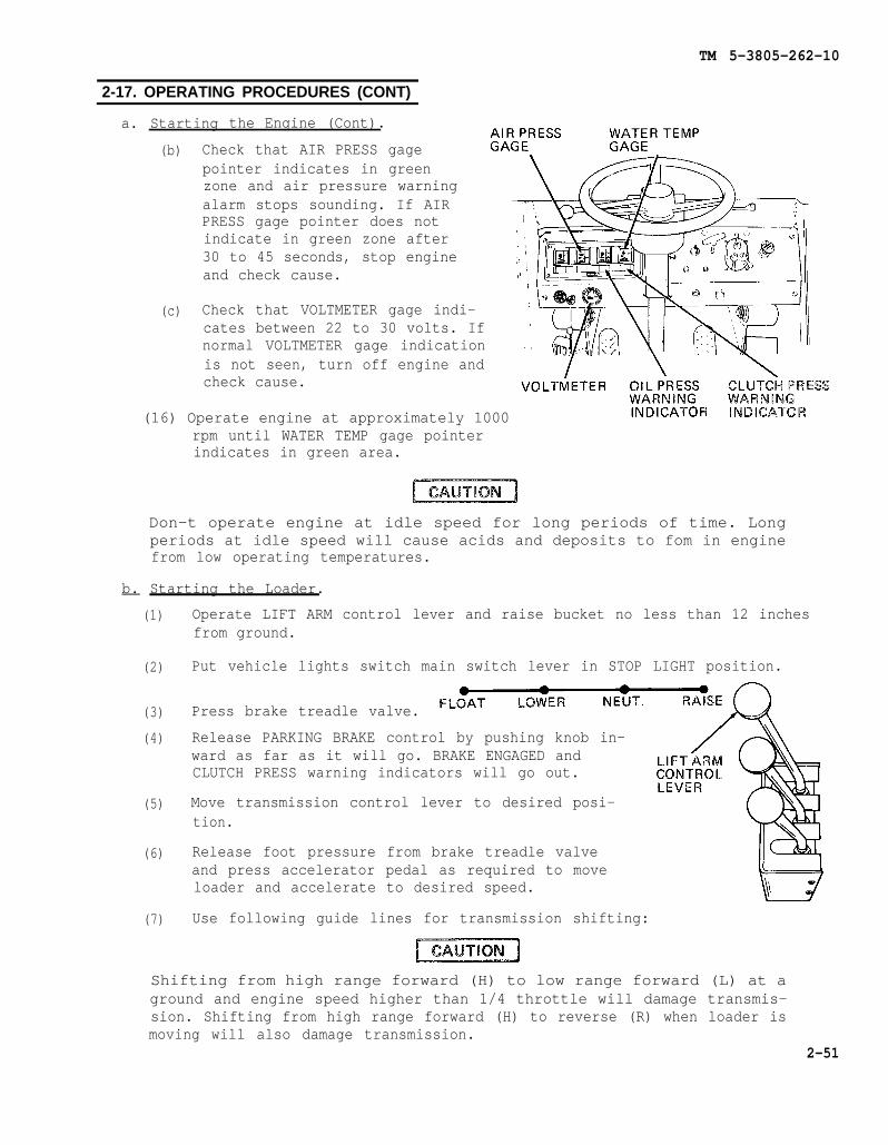
TM 5-3805-262-10
2-17. OPERATING PROCEDURES (CONT)
a. Starting the Engine (Cont).
(b)
(c)
Check that AIR PRESS gagepointer indicates in greenzone and air pressure warningalarm stops sounding. If AIRPRESS gage pointer does notindicate in green zone after30 to 45 seconds, stop engineand check cause.
Check that VOLTMETER gage indi-cates between 22 to 30 volts. Ifnormal VOLTMETER gage indicationis not seen, turn off engine andcheck cause.
(16) Operate engine at approximately 1000rpm until WATER TEMP gage pointerindicates in green area.
Don-t operate engine at idle speed for long periods of time. Longperiods at idle speed will cause acids and deposits to fom in enginefrom low operating temperatures.
b. Starting the Loader.
(1)
(2)
(3)
(4)
(5)
(6)
(7)
Operate LIFT ARM control lever and raise bucket no less than 12 inchesfrom ground.
Put vehicle lights switch main switch lever in STOP LIGHT position.
Press brake treadle valve.
Release PARKING BRAKE control by pushing knob in-ward as far as it will go. BRAKE ENGAGED andCLUTCH PRESS warning indicators will go out.
Move transmission control lever to desired posi-tion.
Release foot pressure from brake treadle valveand press accelerator pedal as required to moveloader and accelerate to desired speed.
Use following guide lines for transmission shifting:
Shifting from high range forward (H) to low range forward (L) at aground and engine speed higher than 1/4 throttle will damage transmis-sion. Shifting from high range forward (H) to reverse (R) when loader ismoving will also damage transmission.
2-51
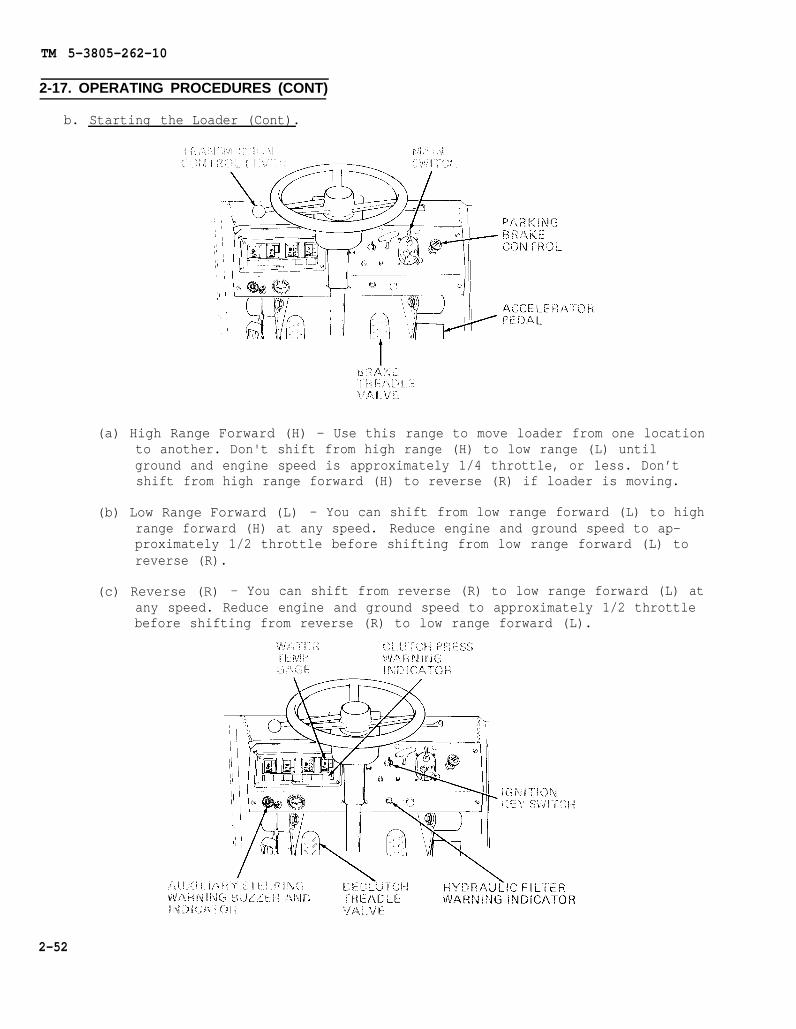
TM 5-3805-262-10
2-17. OPERATING PROCEDURES (CONT)
b. Starting the Loader (Cont).
(a) High Range Forward (H) - Use this range to move loader from one locationto another. Don't shift from high range (H) to low range (L) untilground and engine speed is approximately 1/4 throttle, or less. Don’tshift from high range forward (H) to reverse (R) if loader is moving.
(b) Low Range Forward (L) - You can shift from low range forward (L) to highrange forward (H) at any speed. Reduce engine and ground speed to ap-proximately 1/2 throttle before shifting from low range forward (L) toreverse (R).
(c) Reverse (R) - You can shift from reverse (R) to low range forward (L) atany speed. Reduce engine and ground speed to approximately 1/2 throttlebefore shifting from reverse (R) to low range forward (L).
2-52
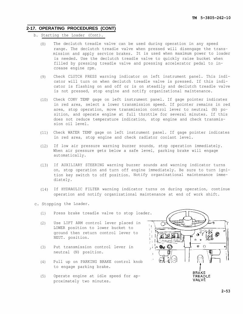
TM 5-3805-262-10
2-17. OPERATING PROCEDURES (CONT)
b. Starting the Loader (Cont).
(8)
(9)
(10)
(11)
(12)
(13)
(14)
The declutch treadle valve can be used during operation in any speedrange. The declutch treadle valve when pressed will disengage the trans-mission and apply service brakes. It is used when maximum power to loaderis needed. Use the declutch treadle valve to quickly raise bucket whenfilled by pressing treadle valve and pressing accelerator pedal to in-crease engine rpm.
Check CLUTCH PRESS warning indicator on left instrument panel. This indi-cator will turn on when declutch treadle valve is pressed. If this indi-cator is flashing on and off or is on steadily and declutch treadle valveis not pressed, stop engine and notify organizational maintenance.
Check CONV TEMP gage on left instrument panel. If gage pointer indicatesin red area, select a lower transmission speed. If pointer remains in redarea, stop operation, move transmission control lever to neutral (N) po-sition, and operate engine at full throttle for several minutes. If thisdoes not reduce temperature indication, stop engine and check transmis-sion oil level.
Check WATER TEMP gage on left instrument panel. If gage pointer indicatesin red area, stop engine and check radiator coolant level.
If low air pressure warning buzzer sounds, stop operation immediately.When air pressure gets below a safe level, parking brake will engageautomatically.
If AUXILIARY STEERING warning buzzer sounds and warning indicator turnson, stop operation and turn off engine immediately. Be sure to turn igni-tion key switch to off position. Notify organizational maintenance imme-diately.
If HYDRAULIC FILTER warning indicator turns on during operation, continueoperation and notify organizational maintenance at end of work shift.
c. Stopping the Loader.
(1) Press brake treadle valve to stop loader.
(2)
(3)
(4)
(5)
Use LIFT ARM control lever placed inLOWER position to lower bucket toground then return control lever toNEUT. position.
Put transmission control lever inneutral (N) position.
Pull up on PARKING BRAKE control knobto engage parking brake.
Operate engine at idle speed for ap-proximately two minutes.
2-53

TM 5-3805-262-10
2-17. OPERATING PROCEDURES (CONT)
c. Stopping the Loader (Cont).
(6)
(7)
Turn ignition key switch to off position.
Pull out SHUT OFF control. When engine hasstopped, push shut off control completely in.
d. Operating the Loader.
(1) Excavating.
Operating on a hillside can beground , etc., change grounddetermine if your machine canramp.
dangerous. Rain, snow, loose gravel, softconditions. Only you, the operator, canbe safely operated on any hillside or
Before you operate on any hillside or ramp, always select low range andnever coast down hill with transmission in neutral (N). To do so couldcause you to lose control of loader and roll over causing loss of lifeor serious injury and extensive property damage.
(a) Use LIFT ARM control lever to raise bucketground.
approximately 12 inches above
2-54
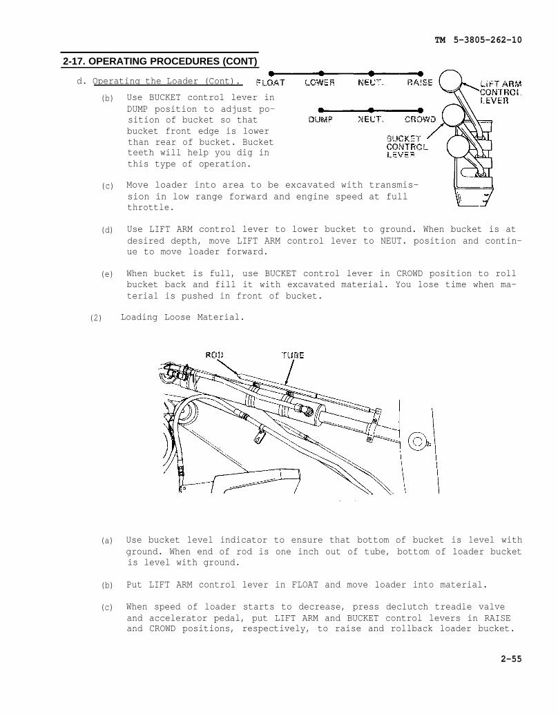
TM 5-3805-262-10
2-17. OPERATING PROCEDURES (CONT)
d. Operating the Loader (Cont).
(b)
(c)
(d)
(e)
(2)
(a)
(b)
(c)
Use BUCKET control lever inDUMP position to adjust po-sition of bucket so thatbucket front edge is lowerthan rear of bucket. Bucketteeth will help you dig inthis type of operation.
Move loader into area to be excavated with transmis-sion in low range forward and engine speed at fullthrottle.
Use LIFT ARM control lever to lower bucket to ground. When bucket is atdesired depth, move LIFT ARM control lever to NEUT. position and contin-ue to move loader forward.
When bucket is full, use BUCKET control lever in CROWD position to rollbucket back and fill it with excavated material. You lose time when ma-terial is pushed in front of bucket.
Loading Loose Material.
Use bucket level indicator to ensure that bottom of bucket is level withground. When end of rod is one inch out of tube, bottom of loader bucketis level with ground.
Put LIFT ARM control lever in FLOAT and move loader into material.
When speed of loader starts to decrease, press declutch treadle valveand accelerator pedal, put LIFT ARM and BUCKET control levers in RAISEand CROWD positions, respectively, to raise and rollback loader bucket.
2-55
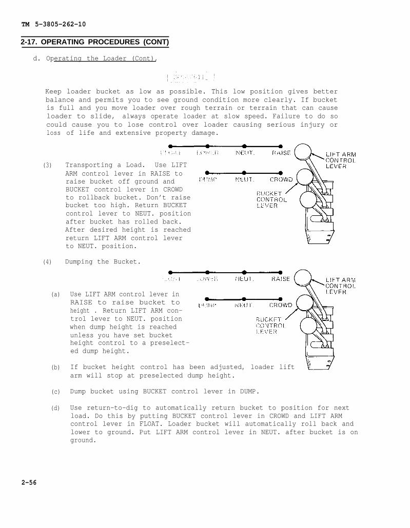
TM 5-3805-262-10
2-17. OPERATING PROCEDURES (CONT)
d. Operating the Loader (Cont),
Keep loader bucket as low as possible. This low position gives betterbalance and permits you to see ground condition more clearly. If bucketis full and you move loader over rough terrain or terrain that can causeloader to slide, always operate loader at slow speed. Failure to do socould cause you to lose control over loader causing serious injury orloss
(3)
(4)
(a)
(b)
(c)
(d)
of life and extensive property damage.
Transporting a Load. Use LIFTARM control lever in RAISE toraise bucket off ground andBUCKET control lever in CROWDto rollback bucket. Don’t raisebucket too high. Return BUCKETcontrol lever to NEUT. positionafter bucket has rolled back.After desired height is reachedreturn LIFT ARM control leverto NEUT. position.
Dumping the Bucket.
Use LIFT ARM control lever inRAISE to raise bucket toheight . Return LIFT ARM con-trol lever to NEUT. positionwhen dump height is reachedunless you have set bucketheight control to a preselect-ed dump height.
If bucket height control has been adjusted, loader liftarm will stop at preselected dump height.
Dump bucket using BUCKET control lever in DUMP.
Use return-to-dig to automatically return bucket to position for nextload. Do this by putting BUCKET control lever in CROWD and LIFT ARMcontrol lever in FLOAT. Loader bucket will automatically roll back andlower to ground. Put LIFT ARM control lever in NEUT. after bucket is onground.
2-56

TM 5-3805-262-10
2-17. OPERATING PROCEDURES (CONT)
d. Operating the Loader (Cont).
(5) Truck Loading.
(a) Use LIFT ARM control lever inRAISE to raise bucket. Moveloader toward side of truck.
(b) Use brake treadle valve to slow loader and declutchtreadle valve to stop loader.
(c) As you move load toward truck, use bucket heightcontrol to automatically position bucket at desireddump height.
(d) Dump load into truck by using BUCKET control lever inDUMP .
(e) Use return-to-dig to position bucket for next cycle. Do this by usingLIFT ARM control lever in FLOAT and BUCKET control lever in CROWD.Bucket will automatically rollback and lower to ground.
(f) After bucket is on ground, return LIFT ARM control lever to NEUT.
2-18. PREPARATION FOR MOVEMENT
a. Driving. The loader may be moved under its own power without any special pre-paration or may be transported on a suitable truck and flatbed trailer. If trans-ported on a flatbed trailer:
(1) Place blocks at front and rearof each trailer wheel.
Be sure ramp is securelyfastened to flat bed trailerto prevent personnel injuryand damage to equipment.
(2) Place ramps between flat bedtrailer and ground.
Before moving loader up ramps, remove all ice, oil or grease from rampto prevent loader from falling and causing death or serious injury andextensive damage to loader. Tell personnel to move away from loader.
NOTE
Ramps shall not provide a grade of more than 40 percent.
2-57

TM 5-3805-262-10
2-18. PREPARATION FOR MOVEMENT (CONT)
a. Driving (Cont) .
(3)
(4)
(5)
Start engine and raise bucket one foot off ground using LIFT ARM controllever in RAISE position then return to NEUT. position.
Using BUCKET control lever in CROWD position, rollback bucket completelythen return BUCKET control lever to NEUT. position.
Secure bucket assembly in rollback position using 12 foot length of chainwith a hook on each end. Position one chain hook on center bucket toothand lift arm brace as shown.
(6) Install transport bracket, stored in tool box, on either lift cylinderassembly rod and secure using capscrew and nut.
(7) Turn off engine.
When performing following step, be sure thatdo so will cause damage to transport bracketand may distort bucket lift arms.
engine is off. Failure toand lift cylinder assembly,
(8) Place LIFT ARM control lever in LOWER position andLift cylinder assembly rod will retract and bucketeye is resting on transport bracket.
slowly lower bucket.will lower until rod
(9) Start engine and slowly move loader up ramps and position on flat bedtrailer.
(10) Pull up on parking brake control to apply parking brake, and turn offengine. Remove key from ignition key switch.
(11) Place transport/service link in locked position.
(12) Make sure transmission and hydraulic control levers are in their neutralpositions.
2-58
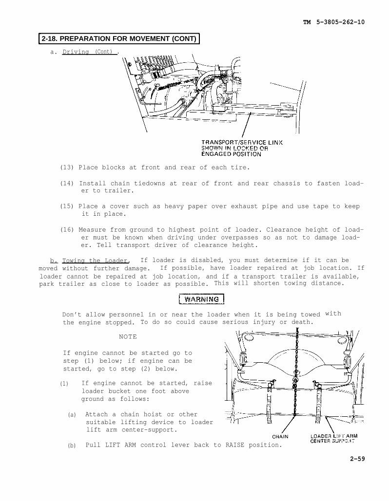
TM 5-3805-262-10
2-18. PREPARATION FOR MOVEMENT (CONT)
a. Driving (Cont) .
(13) Place blocks at front and rear of each tire.
(14) Install chain tiedowns at rear of front and rear chassis to fasten load-er to trailer.
(15) Place a cover such as heavy paper over exhaust pipe and use tape to keepit in place.
(16) Measure from ground to highest point of loader. Clearance height of load-er must be known when driving under overpasses so as not to damage load-er. Tell transport driver of clearance height.
b. Towing the Loader. If loader is disabled, you must determine if it can bemoved without further damage. If possible, have loader repaired at job location. Ifloader cannot be repaired at job location, and if a transport trailer is available,park trailer as close to loader as possible. This will shorten towing distance.
Don’t allow personnel in or near the loader when it is being towedthe engine stopped. To do so could cause serious injury or death.
NOTE
If engine cannot be started go tostep (1) below; if engine can bestarted, go to step (2) below.
(1)
(a)
(b)
If engine cannot be started, raiseloader bucket one foot aboveground as follows:
Attach a chain hoist or othersuitable lifting device to loader
with
lift arm center-support.
Pull LIFT ARM control lever back to RAISE position.
2-59
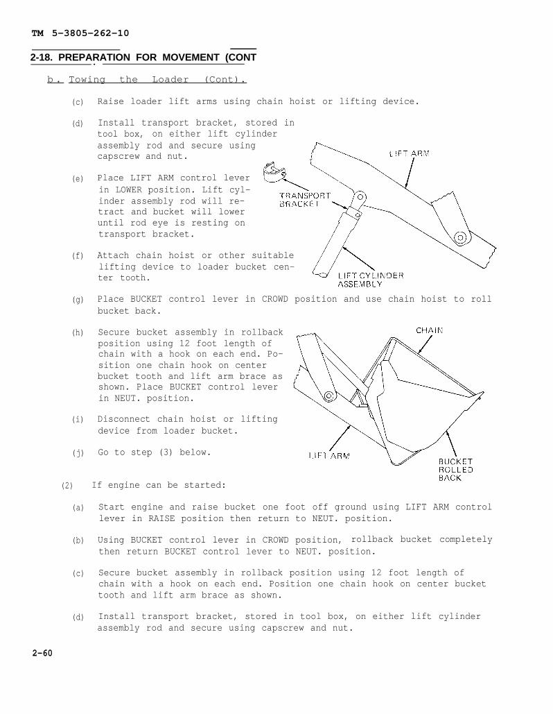
TM 5-3805-262-10
2-18. PREPARATION FOR MOVEMENT (CONT.
b . Towing the Loader (Cont).
(c)
(d)
(e)
(f)
(g)
(h)
(i)
(j)
Raise loader lift arms using chain hoist or lifting device.
Install transport bracket, stored intool box, on either lift cylinderassembly rod and secure usingcapscrew and nut.
Place LIFT ARM control leverin LOWER position. Lift cyl-inder assembly rod will re-tract and bucket will loweruntil rod eye is resting ontransport bracket.
Attach chain hoist or other suitablelifting device to loader bucket cen-ter tooth.
Place BUCKET control lever in CROWD position and use chain hoist to rollbucket back.
Secure bucket assembly in rollbackposition using 12 foot length ofchain with a hook on each end. Po-sition one chain hook on centerbucket tooth and lift arm brace asshown. Place BUCKET control leverin NEUT. position.
Disconnect chain hoist or liftingdevice from loader bucket.
Go to step (3) below.
(2) If engine can be started:
(a)
(b)
(c)
(d)
Start engine and raise bucket one foot off ground using LIFT ARM controllever in RAISE position then return to NEUT. position.
Using BUCKET control lever in CROWD position, rollback bucket completelythen return BUCKET control lever to NEUT. position.
Secure bucket assembly in rollback position using 12 foot length ofchain with a hook on each end. Position one chain hook on center buckettooth and lift arm brace as shown.
Install transport bracket, stored in tool box, on either lift cylinderassembly rod and secure using capscrew and nut.
2-60

TM 5-3805-262-10
2-18. PREPARATION FOR MOVEMENT (CONT)
b. Towing the Loader (Cont).
(e) Turn off engine.
When performing following step, be sure thatdo so will cause damage to transport bracketand may distort bucket lift arms.
engine is off. Failure toand lift cylinder assembly,
(f) Place LIFT ARM control lever in LOWER position and slowly lower bucket.Lift cylinder assembly rod will retract and “bucket will lower until rodeye is resting on transport bracket.
(g) Go to step (3) below.
(3) Place transport/safety link in locked position. If loader is turned toone side and engine is inoperable:
(a) Clear personnel from area.
(b) Pull SHUT OFF control all the way out.
(c) Turn ignition key switch to start position and at the same time turnsteering wheel. When loader is straight, install transport/safety link.Don’t operate starter motor more than 30 seconds at a time withoutallowing two minutes for it to cool.
(d) Place ignition key switch in off position.
2-61
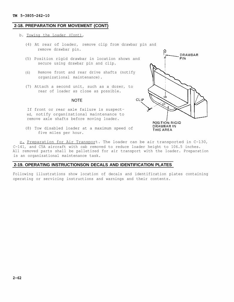
TM 5-3805-262-10
2-18. PREPARATION FOR MOVEMENT (CONT)
b. Towing the Loader (Cont).
(4) At rear of loader, remove clip from drawbar pin andremove drawbar pin.
(5) Position rigid drawbar in location shown andsecure using drawbar pin and clip.
(6) Remove front and rear drive shafts (notifyorganizational maintenance).
(7) Attach a second unit, such as a dozer, torear of loader as close as possible.
NOTE
If front or rear axle failure is suspect-ed, notify organizational maintenance toremove axle shafts before moving loader.
(8) Tow disabled loader at a maximum speed offive miles per hour.
c. Preparation for Air Transport. The loader can be air transported in C-130,C-141, and C5A aircraft with cab removed to reduce loader height to 106.5 inches.All removed parts shall be palletized for air transport with the loader. Preparationis an organizational maintenance task.
2-19. OPERATING INSTRUCTIONSON DECALS AND IDENTIFICATION PLATES
Following illustrations show location of decals and identification plates containingoperating or servicing instructions and warnings and their contents.
2-62

TM 5-3805-262-10
2-19. OPERATING lNSTRUCTIONS ON DECALS AND IDENTIFICATION PLATES (CONT)
2-63
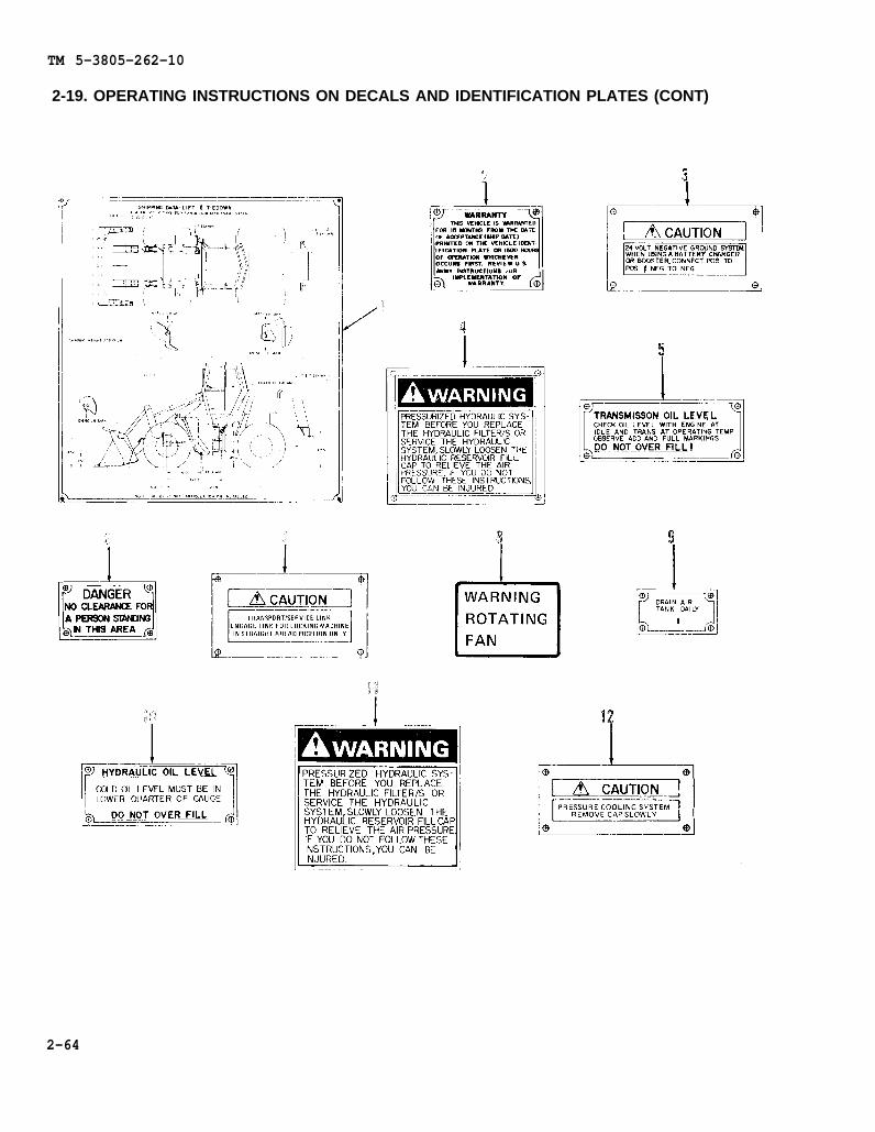
TM 5-3805-262-10
2-19. OPERATING INSTRUCTIONS ON DECALS AND IDENTIFICATION PLATES (CONT)
2-64
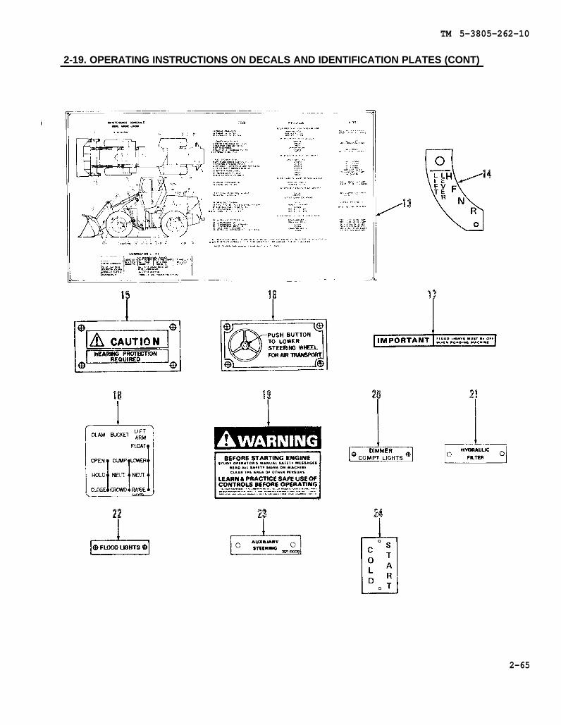
TM 5-3805-262-10
2-19. OPERATING INSTRUCTIONS ON DECALS AND IDENTIFICATION PLATES (CONT)
2-65
TM 5-3805-262-10
Section IV. OPERATION UNDER UNUSUAL CONDITIONS
Para ParaOperation in Unusual Weather . . . . . . 2-20 Lubrication . . . . . . . . . . . 2-21d
Extreme Cold . . . . . . . . . . . . . 2-20a At Halt . . . . . . . . . . . . . . . . 2-21eExtreme Heat . . . . . . . . . . . . 2-20b Bucket Lift Arms andRainy or Humid Conditions . . . . . . 2-20c Pivot Assemblies . . . . . . . . . 2-21f
Operation in Sandy or Dusty Areas . 2-21 Operation in Salt Water Areas . . . . 2-22General . . . . . . . . . . . . . 2-21a Operation at High Altitudes . . . . . . 2-23Cooling System . . . . . . . . . . . 2-21b Operation in Snow . . . . . . . . . . . . . . . . 2-24Air Cleaner . . . . . . . . . . . . . . .. 2-21c Fording 2-25
2-20. OPERATION IN UNUSUAL WEATHER
a. Extreme Cold.
(1) General. Extensive preparation of the loader is required when extreme coldweather is anticipated. Extreme cold causes lubricants to thicken or congeal, pre-sents a risk of freezing batteries and diminishes their electrical efficiency, cancrack electrical insulation to cause short circuits, prevents fuel from vaporizingreadily to form the combustible mixture necessary for starting, and causes variousmaterials to become hard, brittle, and easily damaged. You must make sure thecooling system has been filled with the appropriate anti-freeze solution to protectthe system against sub-freezing temperatures.
(2) Cooling System. Before the cooling system is drained and filled, inspectthe system for leaks and general condition. All deteriorated or damaged hoses mustbe replaced. Make sure that all clamps are tight and that drain cocks are properlyclosed. When anti-freeze is added to the cooling system, be sure ample space isallowed for the required amount of anti-freeze. Be sure you operate the engine for15 minutes to allow the solution to properly mix.
(3) Lubrication. Be sure that the correct grade of lubricant is applied to thelubrication points. If necessary, drain and refill if the lubricant grade is notcorrect for cold weather operation.
(4) Fuel System. Be sure precautions are taken to eliminate water and moisturefrom the fuel system by draining and flushing the fuel tank, and draining off anywater from the fuel tank and filters at the end of each day’s operation, replacingthe fuel filter elements, and completely filling the fuel tank after each operatingperiod to avoid water condensation. The fuel tank must not be allowed to remainpartially empty over long periods of time and all ice and snow must be completelyremoved from around the filler opening before refilling the fuel tank.
(5) Air System. At beginning and end of daily operation, drain water and sedi-ment from the air reservoir.
(6) Engine Operation.
(a) Use the cold weather starting aid to start the engine.
2-66

TM 5-3805-262-10
2-20. OPERATION IN UNUSUAL WEATHER (CONT)
a. Extreme Cold (Cont).
(b) Run the engine at reduced speed only long enough to circulate the oilthrough the engine, then increase speed and warm-up the engine. Low idling speedsduring extremely cold temperature can result in incomplete combustion and heavydeposit formations on the valves.
(c) Cover the radiator if necessary to bring engine up to operating tempera-ture.
(7) At Halt or Parking.
(a)to protect
(b)bucket.
(c)freezes.
(d)
Park loader in sheltered place if possible. Close cab doors and windowsaccessories and controls from ice and snow.
Run loader onto planks to prevent tires from freezing to ground. Block up
Be sure you clean wet snow or mud from tires and cylinders before it
In extremely cold weather, remove the batteries and store them in a mod-erately warm area. Reinstall the batteries just before starting the engine.
b. Extreme Heat.
(1) General. Check temperature gages and lights frequently for indication ofoverheating. Allow engine to idle slowly when it is overheated until temperature isreduced indicated by gage pointer dropping into the green zone.
(2) Cooling System.
(a)
(b)
(c)
(d)
Drain, flush, and refill cooling system.
Check coolant level at frequent intervals and keep radiator cap tight.
Be sure that radiator is free of bugs, dust, and other foreign matter.
Check drive belts tension frequently.
(3) Lubrication. Lubricate the loader with correct grade of lubricants in ac-cordance with the lubrication chart. Change filter elements at shorter intervalsthan normal.
(4) Air Cleaner. Service air cleaner at shorter than normal
(5) At Halt or Parking. Park the loader in a shaded area if
intervals.
possible.
2-67
TM 5-3805-262-10
2-20. OPERATION IN UNUSUAL WEATHER (CONT)
c. Rainy or Humid Conditions. Keep loader protected when not in use. Dry offseat and wiring to prevent formation of mildew. Keep fuel tank full. Service filtersmore frequently than normal. Keep all moving parts well lubricated.
2-21. OPERATION IN DUSTY OR SANDY AREAS
a. General. Sand and dust are abrasive and can cause wear on many parts of theloader. Airborne sand and dust can clog the radiator and air cleaner.
b. Cooling System. Be sure you check the radiator frequently and keep air pass-ages open.
c. Air Cleaner. Reduce service intervals for the air cleaner and clean the aircleaner as often as necessary.
d. Lubrication. Lubricate the loader at more frequent intervals. Clean all fitt-ings and lubrication openings thoroughly before lubricating to prevent entry of dustor sand with the lubricant. Take care to prevent contamination of lubricants withdust or sand.
e. At Halt. When the loader is not in use, close cab windows and doors, and uti-lize what ever means are available to protect the engine compartment from the entryof wind blown dust or sand.
f. Bucket Lift Arms and Pivot Assemblies. Periodically check sliding matingparts for build–up of dust, dirt, or sand. Use a wire brush to remove dust, dirt, orsand build-up.
2-22. OPERATION IN SALT WATER AREAS
Keep loader as clean as possible; after use, wash with fresh water. Keep all lubri-cation points lubricated. Keep all wiring and connections clean and free from corro-sion.
2-23. OPERATION AT HIGH ALTITUDES
Keep a constant watch on coolant level. Add coolant if necessary. Keep close watchon engine instruments during operation.
NOTE
Engine will operate at less than peak performance at high altitude.
2-24. OPERATION IN SNOW
Keep fuel tank full and snow and ice away from fuel filler when servicing the load-er. Close cab windows and doors to keep snow from operating controls and indicatorsand from operator’s seat.
2-68
TM 5-3805-262-10
2-25. FORDING
The loader may safely be subjected to depths up to 30-inches. Observe the followingwhen fording any body of water:
a. Before Fording_. Check depth of the water, allowing for the consistency of thebottom. Don-t attempt to ford even the narrowest stream more than 30-inches deep.Make sure the engine is operating at full efficiency before fording.
b. During Fording. Shift the transmission in low speed range and speed up the en-gine to minimize the danger of stalling. Enter the water slowly to minimize surgesof backwash into the engine compartment. Speed must not exceed three to four mph. Ifstalling or complete submersion occurs, notify higher level of maintenance.
c. After Fording. Lubricate the loader completely; as soon as possible, afterfording.
2-69/(2-70 blank)

TM 5-3805-262-10
CHAPTER 3
MAINTENANCE INSTRUCTIONS
CHAPTER OVERVIEW
The purpose of this chapter is to provide you withlubrication instructions, troubleshooting procedures, andmaintenance procedures to help you keep your equipment ingood operating condition.
Index
Section Title PageI Lubrication Instructions . . . . . . . . . . . . . . . . . . . . . . . 3-1II Troubleshooting Procedures . . .. . . . . . . . . . . . . . . . . . . . 3-3III Maintenance Procedures. . . . . . . . . . . . . . . . . . . . 3-35
Section I. LUBRICATION INSTRUCTIONS
ParaGeneral Lubrication Information . . . . . . . . . . . . . . . . . . 3-1Lubrication Information . . . . . . . . . . . . . . . . . . . . . . . . . . 3-2Lubrication Requirements . . . . . . . . . . . . . . . . . . . . . . . . . 3-3
3-1. GENERAL LUBRICATION INFORMATION
This section contains general lubrication instructions in addition to those contain-ed in the lubrication order.
3-2. LUBRICATION INFORMATION
a. Care of Lubricants. Keep all lubricants in clean, closed containers and storein a dry area away from external heat. Don’t allow dust, dirt, or other foreign mat-ter to mix with lubricants during storage or use. Keep all lubrication equipmentclean and ready for use.
b. Cleaning. Keep all external parts that do not require lubrication free of lu-bricants. Wipe all dirt and other foreign matter from lubrication points using aclean cloth. Clean caps, covers, and plugs and surrounding area before removing themfrom the loader. Clean lubrication points after lubrication to prevent accumulationof foreign matter.
c. Points of Lubrication. Refer to the lubrication order for lubrication points,and intervals of lubrication.
3-3. LUBRICATION REQUIREMENTS
a. For lubrication under normal conditions, refer to the lubrication order.
3-1

TM 5-3805-262-10
3-3. LUBRICATION REQUIREMENTS (CONT)
b. For instructions on lubrication inC), refer to FM 9-207.
weather below zero degree F (-18 degrees
c. For lubrication before and after fording, refer to TM 9-238.
d. After operating in dusty or sandy conditions, clean and inspect all lubrica-tion points. Lubricate loader in accordance with lubrication order.
3-2
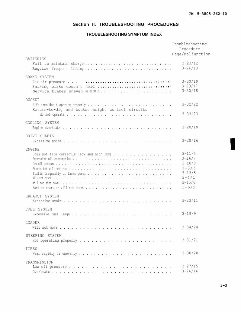
TM 5-3805-262-10
BATTERIESFail toRequire
Section II. TROUBLESHOOTING PROCEDURES
TROUBLESHOOTING SYMPTOM INDEX
maintain chargefrequent filling
BRAKE SYSTEMLow air pressure . . . .Parking brake doesn’tService brakes uneven
BUCKET
. . . . . . . . . . . . . . . . . . . . . . . . . . . . . . . . . .
. . . . . . . . . . . . . . . . . . . . . . . . . . . . . . . . .
TroubleshootingProcedure
Page/Malfunction
holdor erratic . . . . . . . . . . . . . . . . . . . . . . . . .
Lift arms don’t operate properly . . . . . . . . . . . . . . . . . . . . . . . . .Return-to-dig and bucket height control circuits
do not operate . . . . . . . . . . . . . . . . . . . . . . . . . . . . .
COOLING SYSTEMEngine overheats . . . . . . . . .. . . . . . . . . . . . . . . . . . . . . .
DRIVE SHAFTSExcessive noise . . . . . . . . . . . . . . . . . . . . . . . . . . . .
ENGINEDoes not fire correctly (low and high rpm) . . . . . . . . . . . . . . .Excessive oil consumption . . . . . . . . . . . . . . . . . . . . . . . . . . . . . . . .Low oil pressure . . . . . . . . . . . . . . . . . . . . . . . . . . . . . . . . . . . . . . . . .Starts but will not run . . . . . . . . . . . . . . . . . . . . . . . . . . . . . . . . . .Stalls frequently or lacks power . . . . . . . . . . . . . . . . . . . . . . . . .Will not crank . . . . . . . . . . . . . . . . . . . . . . . . . . . . . . . . . . . . . . . . . . .Will not shut down . . . . . . . . . . . . . . . . . . . . . . . . . . . . . . . . . . . . . . .Hard to start or will not start . . . . . . . . . . . . . . . . . . . . . . . . . .
EKHAUST SYSTEMExcessive smoke . . . . . . . . . . . . . . . . . . . . . . . . . . . .
FUEL SYSTEMExcessive fuel usage . . . . . . . . . . . . . . . . . . . . . . . . . .
LOADERWill not move . . . . . . . . . . . . . . . . . . . . . . . . . . . . .
STEERING SYSTEMHot operating properly . . . . . . . . . . . . . . . . . . . . . . .
TIRESWear rapidly or unevenly . . . . . . . . . . . . . . . . . . . . . . . . .
TRANSMISSIONLow oil pressure . . . . . . . . . . . . . . . . . . . . . . . .Overheats . . . . . . . . . . . . . . . . . . . . . . . . . . . . . . .
3-23/123-24/13
3-30/193-29/173-30/18
3-32/22
3-33123
3-20/10
3-28/16
3-11/43-16/73-18/83-8/33-13/53-4/13-15/63-5/2
3-23/11
3-19/9
3-34/24
3-31/21
3-30/20
3-27/153-24/14
3-3

TM 5-3805-262-10
3-4. GENERAL
a. The troubleshooting table (paragraph 3-5) lists common malfunctions which youmay find during operation of the loader. You should perform the tests/inspectionsand corrective actions in the order listed.
b. This manual cannot list all possible malfunctions that may occur or all tests,inspections, and corrective actions. If a malfunction is not listed (except whenmalfunctions and causes are obvious), or is not corrected by listed corrective ac-tions, notify higher level maintenance.
3-5. TROUBLESHOOTING TABLE
MALFUNCTIONTEST OR INSPECTION
CORRECTIVE ACTION
1. ENGINE WILL NOT CRANK
Step 1. Check that transmissioncontrol lever is in N(neutral) position.
Step 2.
a. If transmission controllever is in any positionother than N (neutral),place it in N (neutral)position.
b. If transmission controllever is in N (neutral)position, go to step 2below.
Open radiator grille at rear ofloader.Check for loose, corroded, ordamaged battery cables and con-nections.
a. If battery cable connectionsare loose, notify organiza-tional maintenance.
b. If battery cables or connec-tions are corroded or damaged,notify organizational mainte-nance.
c. If battery cables are okay, goto step 3 below.
3-4
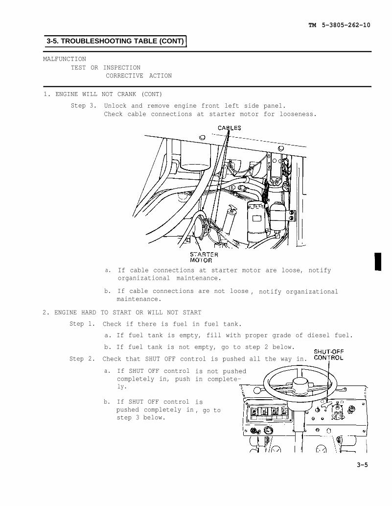
TM 5-3805-262-10
3-5. TROUBLESHOOTING TABLE (CONT)
MALFUNCTIONTEST OR INSPECTION
CORRECTIVE ACTION
1. ENGINE WILL NOT CRANK (CONT)
Step 3. Unlock and remove engine front left side panel.Check cable connections at starter motor for looseness.
a.
b.
If cable connections at starter motor are loose, notifyorganizational maintenance.
If cable connections are not loose , notify organizationalmaintenance.
2. ENGINE HARD TO START OR WILL NOT START
Step 1. Check if there is fuel in fuel tank.
a. If fuel tank is empty, fill with proper grade of diesel fuel.
b. If fuel tank is not empty, go to step 2 below.
Step 2. Check that SHUT OFF control is pushed all the way in.
a.
b.
If SHUT OFF controlcompletely in, pushly.
If SHUT OFF controlpushed completely instep 3 below.
is not pushedin complete-
is, go to
3-5

TM 5-3805-262-10
3-5. TROUBLESHOOTING TABLE (CONT)
MALFUNCTIONTEST OR INSPECTION
CORRECTIVE ACTION
2. ENGINE HARD
Step 3.
Step 4.
TO START OR WILL NOT START (CONT)
Unlock and remove engine rear right side panel.While an assistant pushes and pulls SHUT OFF control, check at fuelinjection pump that fuel shut off lever moves back and forth.
a. If fuel shut off lever moves back and forth, go to step 4 below.
b. If fuel shut off lever does not move, notify organizationalmaintenance.
Tell assistant to push fuel SHUT OFF control all the way in.Check at fuel injection pump that fuel shut off lever moves behindfuel injection pump.Tell assistant to start engine while you grasp fuel shut off leverand move it towards rear of loader.Engine should start.
a. If engine starts, notify organizational maintenance to adjustSHUT OFF control.
b. If engine does not start, go to step 5 below.
3-6

TM 5-3805-262-10
3-5. TROUBLESHOOTING TABLE (CONT)
MALFUNCTIONTEST OR INSPECTION
CORRECTIVE ACTION
2. ENGINE HARD TO START OR WILL NOT START (CONT)
Step 5. Check if restriction indicator red band isvisible.
a. If red band is visible, pressreset button on top of indica-tor and check that red banddisappears from view. (If redband does not disappear fromview, notify organizationalmaintenance that restrictionindicator is defective.)Crank engine and check if redband reappears; if red band isvisible, service air cleaner.
Step 6.
b. Ifto
red band is not visible, gostep 6 below.
and open radiatorat rear of loader.
UnlockgrilleCheck for loose, corroded,or damaged battery cablesand connections.
a. If battery cable connec-tions are loose, notifyorganizational mainte-nance.
b. If battery cables orconnections are corrodedor damaged, notify or-ganizational mainte-nance.
c. If battery cables are okay, go to step 7 below.
3-7
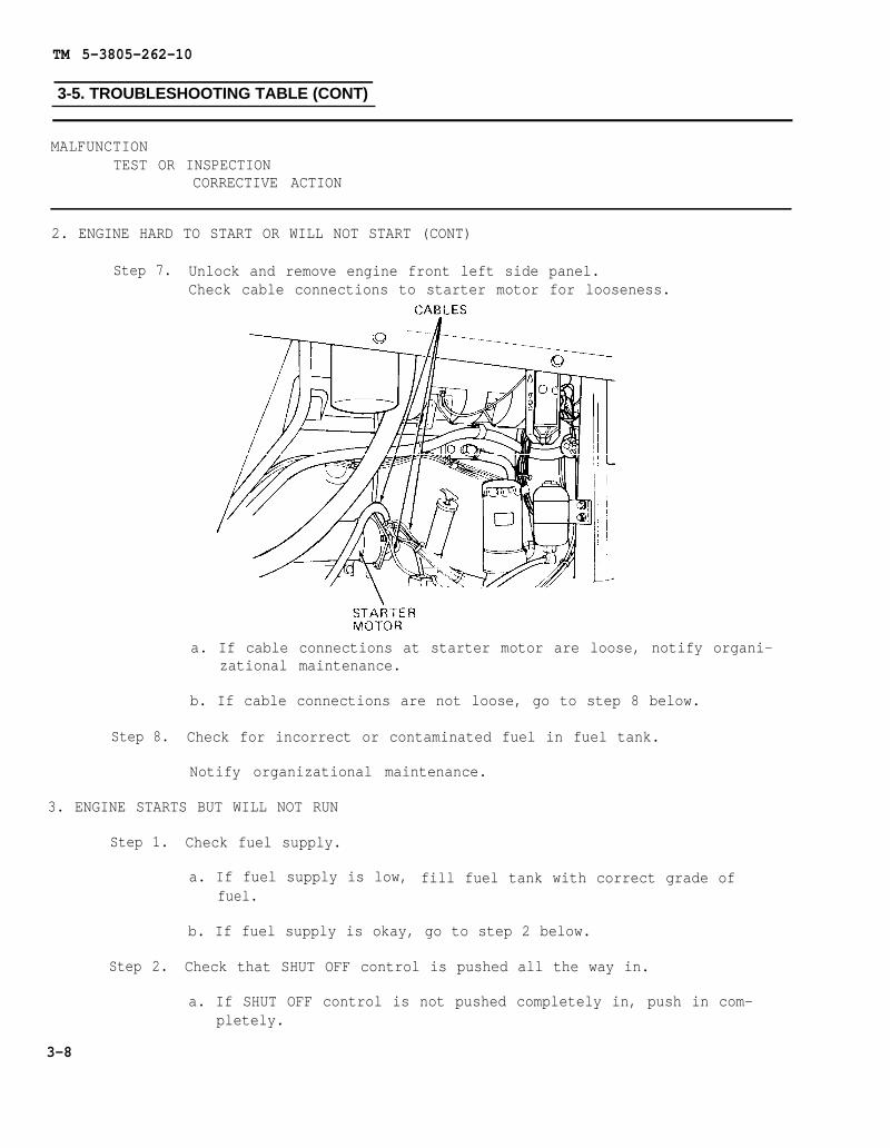
TM 5-3805-262-10
3-5. TROUBLESHOOTING TABLE (CONT)
MALFUNCTIONTEST OR INSPECTION
CORRECTIVE ACTION
2. ENGINE HARD TO START OR WILL NOT START (CONT)
Step 7. Unlock and remove engine front left side panel.Check cable connections to starter motor for looseness.
a. If cable connections at starter motor are loose, notify organi-zational maintenance.
b. If cable connections are not loose, go to step 8 below.
Step 8. Check for incorrect or contaminated fuel in fuel tank.
Notify organizational maintenance.
3. ENGINE STARTS BUT WILL NOT RUN
Step 1. Check fuel supply.
a. If fuel supply is low, fill fuel tank with correct grade offuel.
b. If fuel supply is okay, go to step 2 below.
Step 2. Check that SHUT OFF control is pushed all the way in.
a. If SHUT OFF control is not pushed completely in, push in com-pletely.
3-8
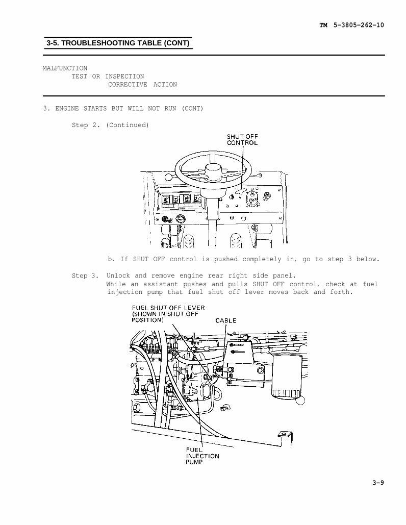
TM 5-3805-262-10
3-5. TROUBLESHOOTING TABLE (CONT)
MALFUNCTIONTEST OR INSPECTION
CORRECTIVE ACTION
3. ENGINE STARTS BUT WILL NOT RUN (CONT)
Step 2. (Continued)
b. If SHUT OFF control is pushed completely in, go to step 3 below.
Step 3. Unlock and remove engine rear right side panel.While an assistant pushes and pulls SHUT OFF control, check at fuelinjection pump that fuel shut off lever moves back and forth.
3-9

TM 5-3805-262-10
3-5. TROUBLESHOOTING TABLE (CONT)
MALFUNCTIONTEST OR INSPECTION
CORRECTIVE ACTION
3. ENGINE STARTS BUT WILL NOT RUN (CONT)
Step 3. (Continued]
a. If fuel shut off lever
b. If fuel shut off levermaintenance.
moves back and forth, go to step 4 below.
does not move, notify organizational
Step 4. Tell assistant to push fuel SHUT OFF control all the way in.Check at fuel injection pump that fuel shut off lever moves behindfuel injection pump.Tell assistant to start engine while you grasp fuel shut off leverand move it towards rear of loader.Engine should start.
a. If engine starts, notify organizational maintenance to adjustSHUT OFF control.
b. If engine does not start, go to step 5 below.
Step 5. Check if restriction indicator red band isvisible.
a.
b.
If red band is visible, pressreset button on top of indica-tor and check that red banddisappears from view. (If redband does not disappear fromview, notify organizationalmaintenance that restrictionindicator is defective.)Crank engine and check if redband reappears; if red band isvisible, service air cleaner.
If red band is not visible, go to step 6 below.
Step 6. Check fuel injector lines for fuel leaks.
a. If fuel injector lines are leaking, notify organizationalmaintenance.
3-10
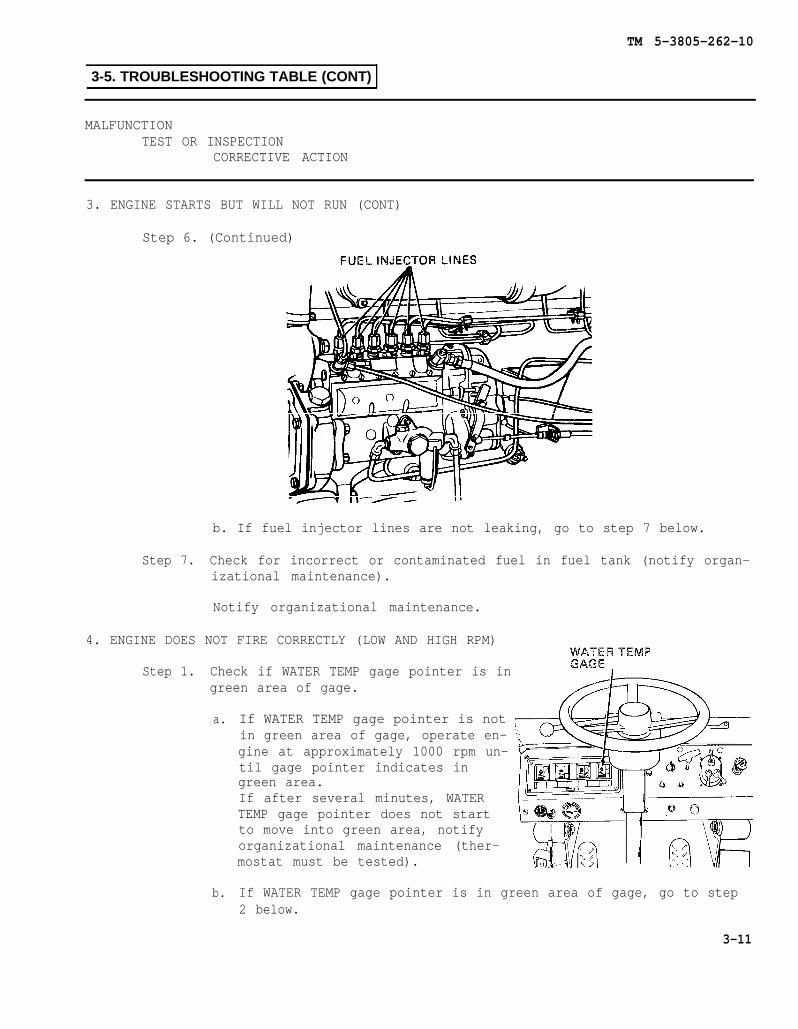
TM 5-3805-262-10
3-5. TROUBLESHOOTING TABLE (CONT)
MALFUNCTIONTEST OR INSPECTION
CORRECTIVE ACTION
3. ENGINE STARTS BUT WILL NOT RUN (CONT)
Step 6. (Continued)
b. If fuel injector lines are not leaking, go to step 7 below.
Step 7. Check for incorrect or contaminated fuel in fuel tank (notify organ-izational maintenance).
Notify organizational maintenance.
4. ENGINE DOES NOT FIRE CORRECTLY (LOW AND HIGH RPM)
Step 1. Check if WATER TEMP gage pointer is ingreen area of gage.
a.
b.
If WATER TEMP gage pointer is notin green area of gage, operate en-gine at approximately 1000 rpm un-til gage pointer indicates ingreen area.If after several minutes, WATERTEMP gage pointer does not startto move into green area, notifyorganizational maintenance (ther-mostat must be tested).
If WATER TEMP gage pointer is in green area of gage, go to step2 below.
3-11
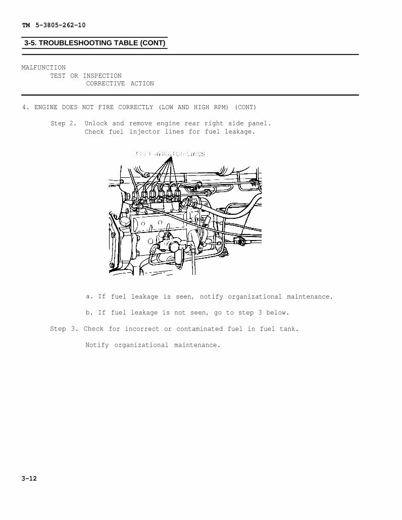
TM 5-3805-262-10
3-5. TROUBLESHOOTING TABLE (CONT)
MALFUNCTIONTEST OR INSPECTION
CORRECTIVE ACTION
4. ENGINE DOES NOT FIRE CORRECTLY (LOW AND HIGH RPM) (CONT)
Step 2. Unlock andCheck
a. If
b. If
Step 3. Check
fuelremove engine rear right side panel.injector lines for fuel leakage.
fuel leakage is seen, notify organizational maintenance.
fuel leakage is not seen, go to step 3 below.
for incorrect or contaminated fuel in fuel tank.
Notify organizational maintenance.
3-12

TM 5-3805-262-10
3-5. TROUBLESHOOTING TABLE (CONT)
MALFUNCTIONTEST OR INSPECTION
CORRECTIVE ACTION
5. ENGINE STALLS FREQUENTLY OR LACKS POWER
Step 1. Check that SHUT OFF control is pushed all the wayin.
a.
b.
If SHUT OFF control is not pushedcompletely in, push in complete-ly .
If SHUT OFF control ispushed completely in, go tostep 2 below.
Step 2. Unlock and remove engine rear right side panel.Turn off engine and check and ensure that SHUT OFF lever is com-pletely pushed in.At fuel injection pump, try to move fuel shut off lever further torear of loader.
3-13

TM 5-3805-262-10
3-5. TROUBLESHOOTING TABLE (CONT)
MALFUNCTIONTEST OR INSPECTION
CORRECTIVE ACTION
5. ENGINE STALLS FREQUENTLY OR LACKS POWER (CONT)
Step 2. (Continued)
a. If fuel shut off lever can be moved furthernotify organizational maintenance to adjustcable.
b. If fuel shut off lever can not3 below.
Step 3. Check if restriction indicator redvisible.
be moved any
band is
b. If red band is not visible, goto step 4 below.
a. If red band is visible, pressreset button on top of indicate.and check that red band disap-pears from view. (If red banddoes not disappear from view,notify organizational mainte-nance that restriction indicatoris defective.)Crank engine and check if redband reappears; if red band isvisible, service air cleaner.
Step 4. Check WATER TEMP gage for high coolanttemperature.
a.
b.
c.
If WATER TEMP gage indi-cates high coolant tempera-ture, notify organizational
to rear of loader,SHUT OFF control
further, go to step
maintenance - (mechanicaldrag exists).
If WATER TEMP gage indi-cates normal coolant tem-perature, go to step 5below.
If WATER TEMP gage indi-cates below normal coolanttemperature, notify organi-zational maintenance (waterthermostat must be tested).
3-14

TM 5-3805-262-10
3-5. TROUBLESHOOTING TABLE (CONT)
MALFUNCTIONTEST OR INSPECTION
CORRECTIVE ACTION
5. ENGINE STALLS FREQUENTLY OR LACKS POWER (CONT)
Step 5. Remove engine front left side panel.Check engine oil level for level exceeding full mark on dipstick.
6.
a. If oil level is above dipstick full mark, notify organizationalmaintenance to drain oil.
b. If oil level is okay, go to step 6 below.
Step 6. Check for fuel contamination and condensation in fuel tank.
Notify organizational maintenance.
ENGINE WILL
Step 1.
NOT SHUT DOWN
Check if fuel SHUT OFF control is completely pulledout
a.
b.
If fuel SHUT OFF control ispulled out completely, pullcompletely to stop engine.
If fuel SHUT OFF lever ispulled out completely andengine is still operat-ing, go to step 2 below.
notout
3-15

TM 5-3805-262-10
3-5. TROUBLESHOOTING TABLE (CONT)
MALFUNCTIONTEST OR INSPECTION
CORRECTIVE ACTION
6. ENGINE WILL NOT SHUT DOWN (CONT)
Step 2. Unlock and remove engine rear right side panel.Check if cable is connected to fuel shut off lever and if lever isin position shown.
Move fuel injection pump shut offNotify organizational maintenanceto fuel injection pump fuel shut off lever.
lever to position shown.to check connection of cable
7. EXCESSIVE OIL CONSUMPTION
Step 1. Check ground under loader for oil leaks from engine oil filter oroil pan.
a. If oil leaks are observed, notify organizational maintenance.
b. If oil leaks are not observed, go to step 2 below.
Step 2. Try to determine what weight oil is used in engine crankcase (referto LO 5-3805-262-12 for correct weight oil to be used).
a. If too light of an engine oil is used, notify organizationalmaintenance to drain and refill engine crankcase with correctweight oil (refer to LO 5-3805-262-12).
b. If weight of engine oil is okay, go to step 3 below.
3-16

TM 5-3805-262-10
3-5. TROUBLESHOOTING TABLE (CONT)
MALFUNCTIONTEST OR INSPECTION
CORRECTIVE ACTION
7. EXCESSIVE OIL CONSUMPTION (CONT)
Step 3. Unlock and open radiator cap access panel.
Remove radiator cap slowly to relieve pressure beforecompletely removing when engine is hot. Failure to do socould cause severe bums due to hot steam scalding you. Ifyou are scalded by hot steam, seek medical aid immediately.
Remove radiator cap and inspect coolant for lubricating oilcontaminant ion.
a. If coolant is contaminated with oil, notify organizationalmaintenance (engine oil cooler must be repaired or replaced).
b. If coolant is not contaminated with oil, notify organizationalmaintenance.
3-17

TM 5-3805-262-10
3-5. TROUBLESHOOTING TABLE (CONT)
MALFUNCTIONTEST OR INSPECTION
CORRECTIVE ACTION
8. LOW ENGINE OIL PRESSURE (ENGINE OIL PRESSURE WARNING INDICATOR LIGHTS)
Step 1. Unlock and remove engine front left side panel.Check engine oil level.
a. Add engine oil if oil level is not between dipstick full and addmarks.
b. If oil level is okay, go to step 2 below.
Step 2. Check engine oil for dirty condition by removing dipstick, wipingbetween thumb and forefinger and noting if oil feels gritty andlooks dirty.
a. If oil feels gritty and looks dirty, notify organizational main-tenance to drain oil, replace oil filter, and refill with oil.
b. If oil is okay, go to step 3 below.
Step 3. Try to determine what weight oil is used in engine crankcase (referto LO 5-3805-262-12 for correct weight oil to be used).
a. If too light of an engine oil is used, notify organizationalmaintenance to drain and refill engine crankcase with correctweight oil (refer to LO 5-3805-262-12).
b. If weight of engine oil is okay, go to step 4 below.
3-18
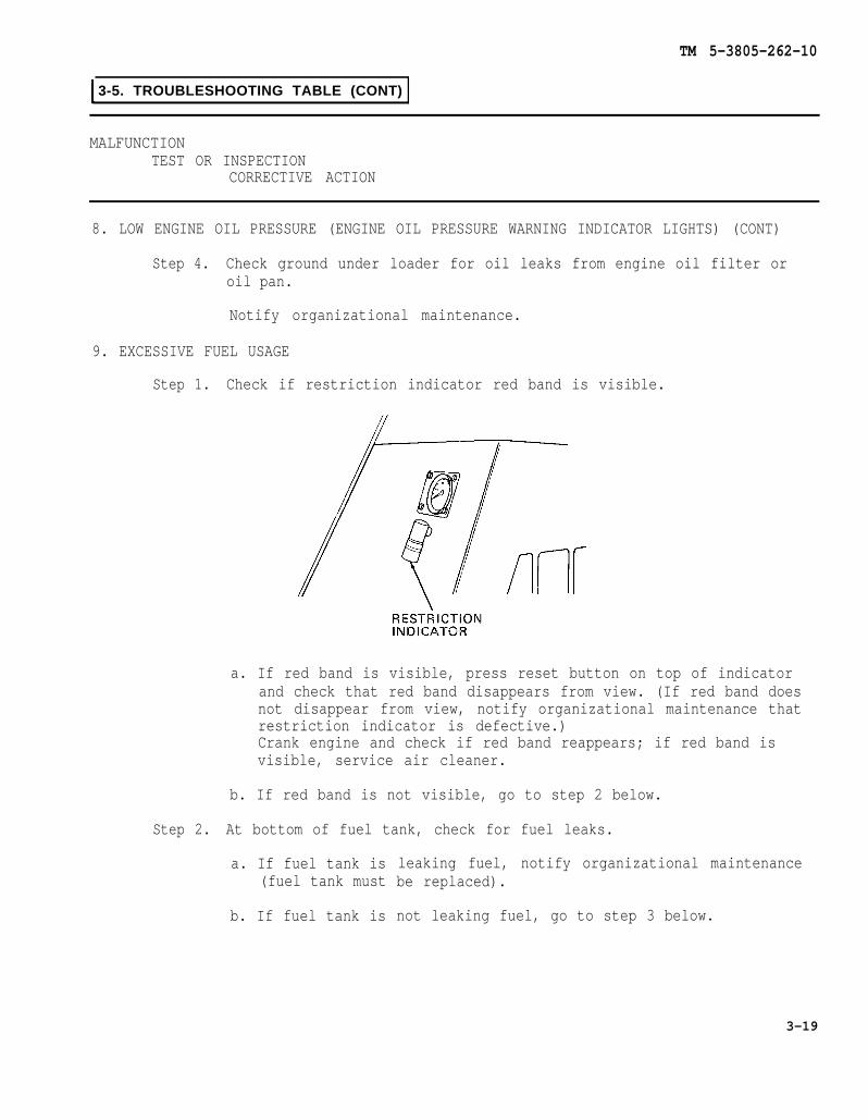
TM 5-3805-262-10
3-5. TROUBLESHOOTING TABLE (CONT)
MALFUNCTIONTEST OR INSPECTION
CORRECTIVE ACTION
8. LOW ENGINE OIL PRESSURE (ENGINE OIL PRESSURE WARNING INDICATOR LIGHTS) (CONT)
Step 4. Check ground under loader for oil leaks from engine oil filter oroil pan.
Notify organizational maintenance.
9. EXCESSIVE FUEL USAGE
Step 1. Check if restriction indicator red band is visible.
a. If red band is visible, press reset button on top of indicatorand check that red band disappears from view. (If red band doesnot disappear from view, notify organizational maintenance thatrestriction indicator is defective.)Crank engine and check if red band reappears; if red band isvisible, service air cleaner.
b. If red band is not visible, go to step 2 below.
Step 2. At bottom of fuel tank, check for fuel leaks.
a. If fuel tank is(fuel tank must
b. If fuel tank is
leaking fuel, notify organizational maintenancebe replaced).
not leaking fuel, go to step 3 below.
3-19

TM 5-3805-262-10
3-5. TROUBLESHOOTING TABLE (CONT)
MALFUNCTIONTEST OR INSPECTION
CORRECTIVE ACTION
9. EXCESSIVE FUEL USAGE (CONT)
Step 3. Unlock and remove engine rear rightside panel.Inspect fuel injector lines for fuelleaks.
a. If fuel injector lines areleaking, notify organizationalmaintenance.
b. If fuel injector lines areokay, notify organizationalmaintenance.
10. ENGINE OVERHEATS (WATER TEMP GAGE INDICATES INRED ZONE)
Step 1. Turn engine off.Unlock and remove engine rearleft side panel.Check alternator drive beltsfor loose condition.Press drive belts in approxi-mate center with your hand.Drive belts should not depressmore than 1/2 inch approxi-mately.
a. If you are able to depressalternator drive beltsmore then 1/2 inch, notifyorganizational maintenanceto adjust drive belts.
b. If alternator drive beltsare okay, go to step 2below.
3-20
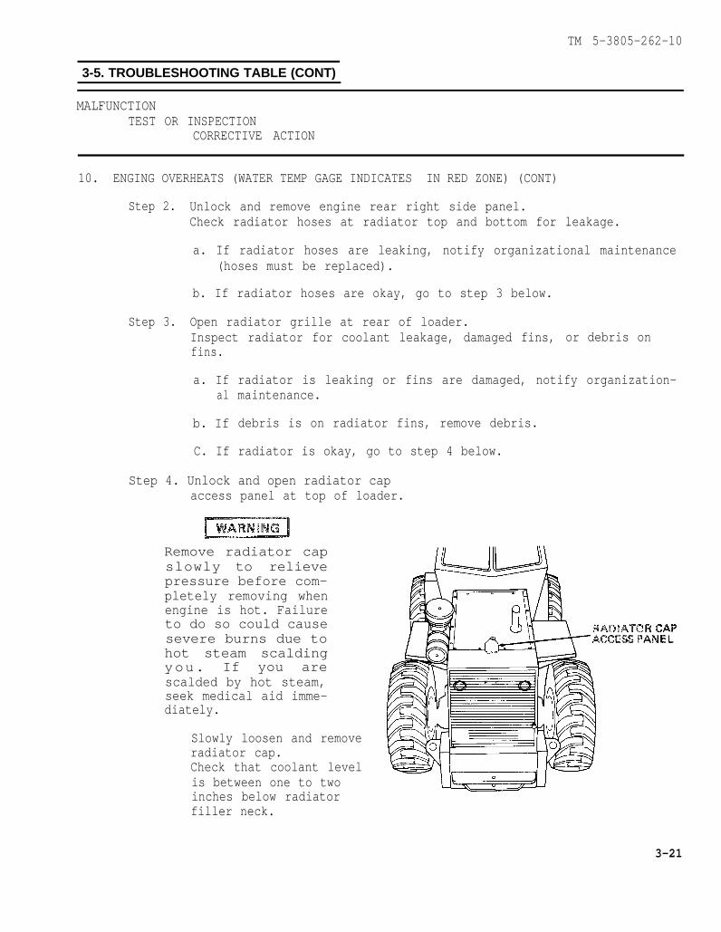
TM 5-3805-262-10
3-5. TROUBLESHOOTING TABLE (CONT)
MALFUNCTIONTEST OR INSPECTION
CORRECTIVE ACTION
10. ENGING OVERHEATS (WATER TEMP GAGE INDICATES IN RED ZONE) (CONT)
Step 2. Unlock and remove engine rear right side panel.Check radiator hoses at radiator top and bottom for leakage.
a. If radiator hoses are leaking, notify organizational maintenance(hoses must be replaced).
b. If radiator hoses are okay, go to step 3 below.
Step 3. Open radiator grille at rear of loader.Inspect radiator for coolant leakage, damaged fins, or debris onfins.
a. Ifal
b. If
C. If
radiator is leaking or fins are damaged, notify organization-maintenance.
debris is on radiator fins, remove debris.
radiator is okay, go to step 4 below.
Step 4. Unlock and open radiator capaccess panel at top of loader.
Remove radiator capslowly to relievepressure before com-pletely removing whenengine is hot. Failureto do so could causesevere burns due tohot steam scaldingyou. If you arescalded by hot steam,seek medical aid imme-diately.
Slowly loosen and removeradiator cap.Check that coolant levelis between one to twoinches below radiatorfiller neck.
3-21
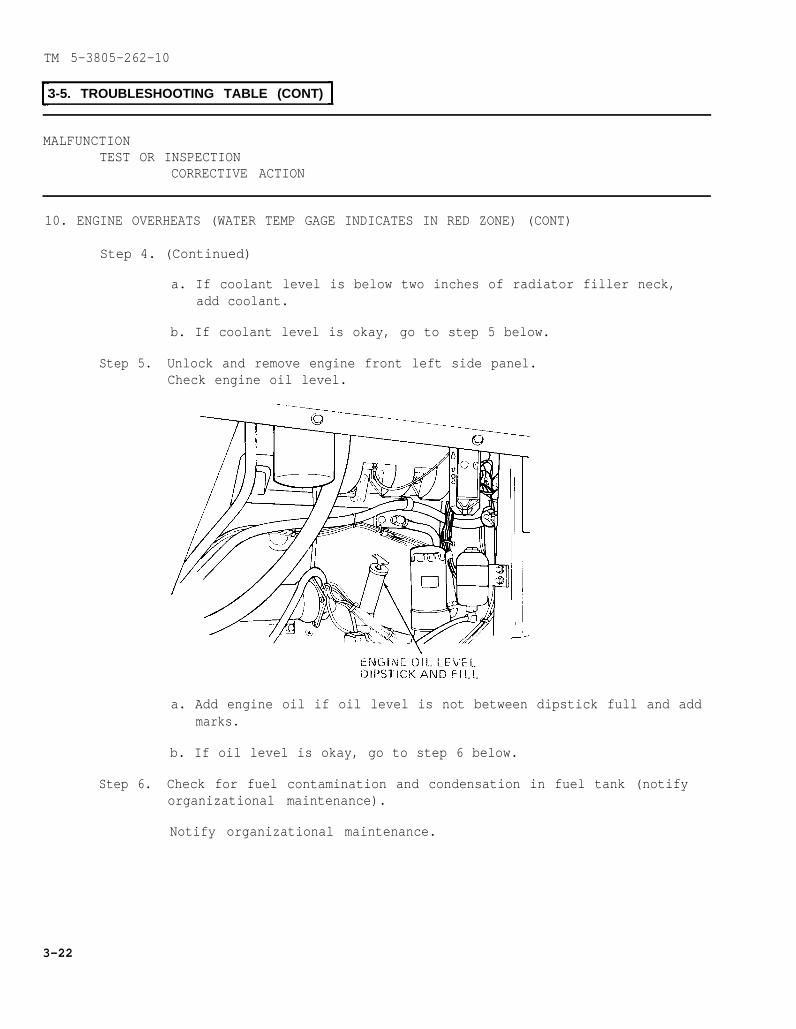
TM 5-3805-262-10
3-5. TROUBLESHOOTING TABLE (CONT)
MALFUNCTIONTEST OR INSPECTION
CORRECTIVE ACTION
10. ENGINE OVERHEATS (WATER TEMP GAGE INDICATES IN RED ZONE) (CONT)
Step 4. (Continued)
a. If coolant level is below two inches of radiator filler neck,add coolant.
b. If coolant level is okay, go to step 5 below.
Step 5. Unlock and remove engine front left side panel.Check engine oil level.
a. Add engine oil if oil level is not between dipstick full and addmarks.
b. If oil level is okay, go to step 6 below.
Step 6. Check for fuel contamination and condensation in fuel tank (notifyorganizational maintenance).
Notify organizational maintenance.
3-22
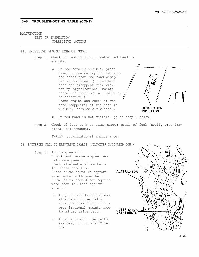
TM 5-3805-262-10
3-5. TROUBLESHOOTING TABLE (CONT)
MALFUNCTIONTEST OR INSPECTION
CORRECTIVE ACTION
11. EXCESSIVE ENGINE EXHAUST SMOKE
Step 1. Check if restriction indicator red band isvisible.
a. If red band is visible, pressreset button on top of indicatorand check that red band disap-pears from view. (If red banddoes not disappear from view,notify organizational mainte-nance that restriction indicatoris defective.)Crank engine and check if redband reappears; if red band isvisible, service air cleaner.
b. If red band is not visible, go to step 2 below.
Step 2. Check if fuel tank contains proper grade of fuel (notify organiza-tional maintenance).
Notify organizational maintenance.
12. BATTERIES FAIL TO MAINTAINE CHARGE (VOLTMETER INDICATED LOW )
Step 1. Turn engine off.Unlock and remove engine rearleft side panel.Check alternator drive beltsfor loose condition.Press drive belts in approxi-mate center with your hand.Drive belts should not depressmore than 1/2 inch approxi-mately.
a. If you are able to depressalternator drive beltsmore than 1/2 inch, notifyorganizational maintenanceto adjust drive belts.
b. If alternator drive beltsare okay, go to step 2 be-low.
3-23
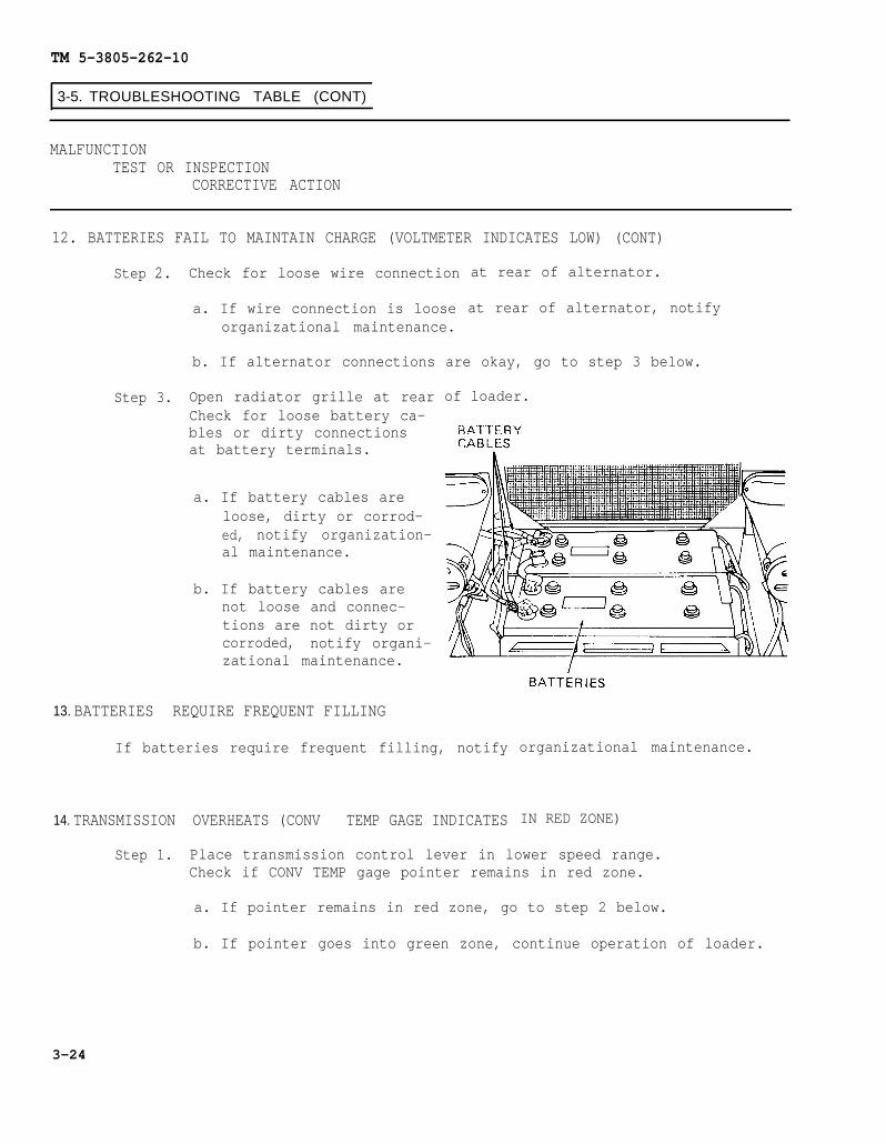
TM 5-3805-262-10
3-5. TROUBLESHOOTING TABLE (CONT)
MALFUNCTIONTEST OR INSPECTION
CORRECTIVE ACTION
12. BATTERIES FAIL TO MAINTAIN CHARGE (VOLTMETER INDICATES LOW) (CONT)
Step 2. Check for loose wire connection
a. If wire connection is looseorganizational maintenance.
at rear of alternator.
at rear of alternator, notify
b. If alternator connections are okay, go to step 3 below.
Step 3. Open radiator grille at rearCheck for loose battery ca-bles or dirty connectionsat battery terminals.
a. If battery cables areloose, dirty or corrod-ed, notify organization-al maintenance.
b. If battery cables arenot loose and connec-tions are not dirty orcorroded, notify organi-zational maintenance.
of loader.
13. BATTERIES REQUIRE FREQUENT FILLING
If batteries require frequent filling, notify
14. TRANSMISSION OVERHEATS (CONV TEMP GAGE INDICATES
organizational maintenance.
IN RED ZONE)
Step 1. Place transmission control lever in lower speed range.Check if CONV TEMP gage pointer remains in red zone.
a. If pointer remains in red zone, go to step 2 below.
b. If pointer goes into green zone, continue operation of loader.
3-24
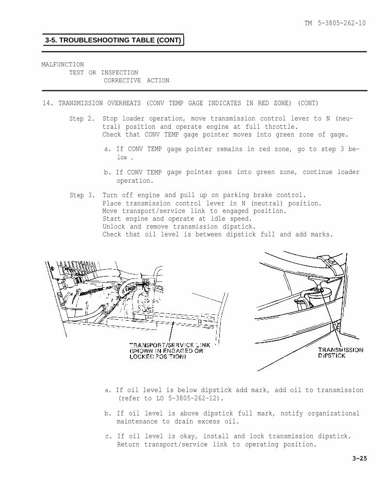
TM 5-3805-262-10
3-5. TROUBLESHOOTING TABLE (CONT)
MALFUNCTIONTEST OR INSPECTION
CORRECTIVE ACTION
14. TRANSMISSION OVERHEATS (CONV TEMP GAGE INDICATES IN RED ZONE) (CONT)
Step 2.
Step 3.
Stop loader operation, move transmission control lever to N (neu-tral) position and operate engine at full throttle.Check that CONV TEMP gage pointer moves into green zone of gage.
a. If CONV TEMPlow .
b. If CONV TEMPoperation.
Turn off engine
gage pointer remains in red zone, go to step 3 be-
gage pointer goes into green zone, continue loader
and pull up on parking brake control.Place transmission control lever in N (neutral) position.Move transport/service link to engaged position.Start engine and operate at idle speed.Unlock and remove transmission dipstick.Check that oil level is between dipstick full and add marks.
a. If oil level is below dipstick add mark, add oil to transmission(refer to LO 5-3805-262-12).
b. If oil level is above dipstick full mark, notify organizationalmaintenance to drain excess oil.
c. If oil level is okay, install and lock transmission dipstick.Return transport/service link to operating position.
3-25

TM 5-3805-262-10
3-5. TROUBLESHOOTING TABLE (CONT)
MALFUNCTIONTEST OR INSPECTION
CORRECTIVE ACTION
14. TRANSMISSION OVERHEATS (CON TEMP GAGE INDICATES IN RED ZONE) (CONT)
Step 3. (Continued)
Be sure transport/service link is disengaged before drivingvehicle. Failure to do so could cause serious injury ordeath due to loss of steering control.
Turn off engine.Go to step 4 below.
Step 4. Open radiator grille at rearInspect radiator for coolantfins.
a. Ifal
b. If
c. If
radiator is leaking ormaintenance.
of loader.leakage, damaged fins, or debris on
fins are damaged, notify organization-
debris is on radiator fins, remove debris.
radiator is okay, notify organizational maintenance.
3-26
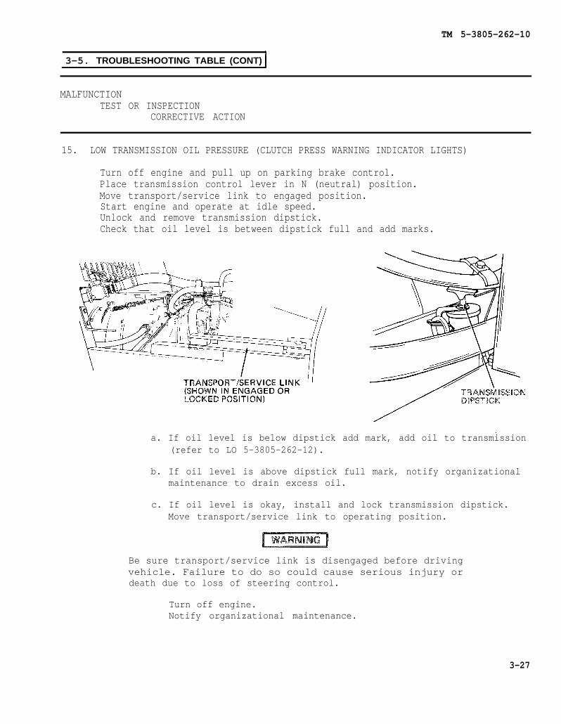
TM 5-3805-262-10
3-5. TROUBLESHOOTING TABLE (CONT)
MALFUNCTIONTEST OR INSPECTION
CORRECTIVE ACTION
15. LOW TRANSMISSION OIL PRESSURE (CLUTCH PRESS WARNING INDICATOR LIGHTS)
Turn off engine and pull up on parking brake control.Place transmission control lever in N (neutral) position.Move transport/service link to engaged position.Start engine and operate at idle speed.Unlock and remove transmission dipstick.Check that oil level is between dipstick full and add marks.
a. If oil level is below dipstick add mark, add oil to transmission(refer to LO 5-3805-262-12).
b. If oil level is above dipstick full mark, notify organizationalmaintenance to drain excess oil.
c. If oil level is okay, install and lock transmission dipstick.Move transport/service link to operating position.
Be sure transport/service link is disengaged before drivingvehicle. Failure to do so could cause serious injury ordeath due to loss of steering control.
Turn off engine.Notify organizational maintenance.
3-27
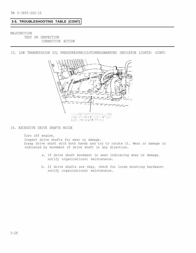
TM 5-3805-262-10
3-5. TROUBLESHOOTING TABLE (CONT)
MALFUNCTIONTEST OR INSPECTION
CORRECTIVE ACTION
15. LOW TRANSMISSION OIL PRESSURESURE(CLUTCHRESSWARNING INDICATOR LIGHTS) (CONT)
16. EXCESSIVE DRIVE SHAFTS NOISE
Turn off engine.Inspect drive shafts for wear or damage.Grasp drive shaft with both hands and try to rotate it. Wear or damage isindicated by movement of drive shaft in any direction.
a. If drive shaft movement is seen indicating wear or damage,notify organizational maintenance.
b. If drive shafts are okay, check for loose mounting hardware;notify organizational maintenance.
3-28
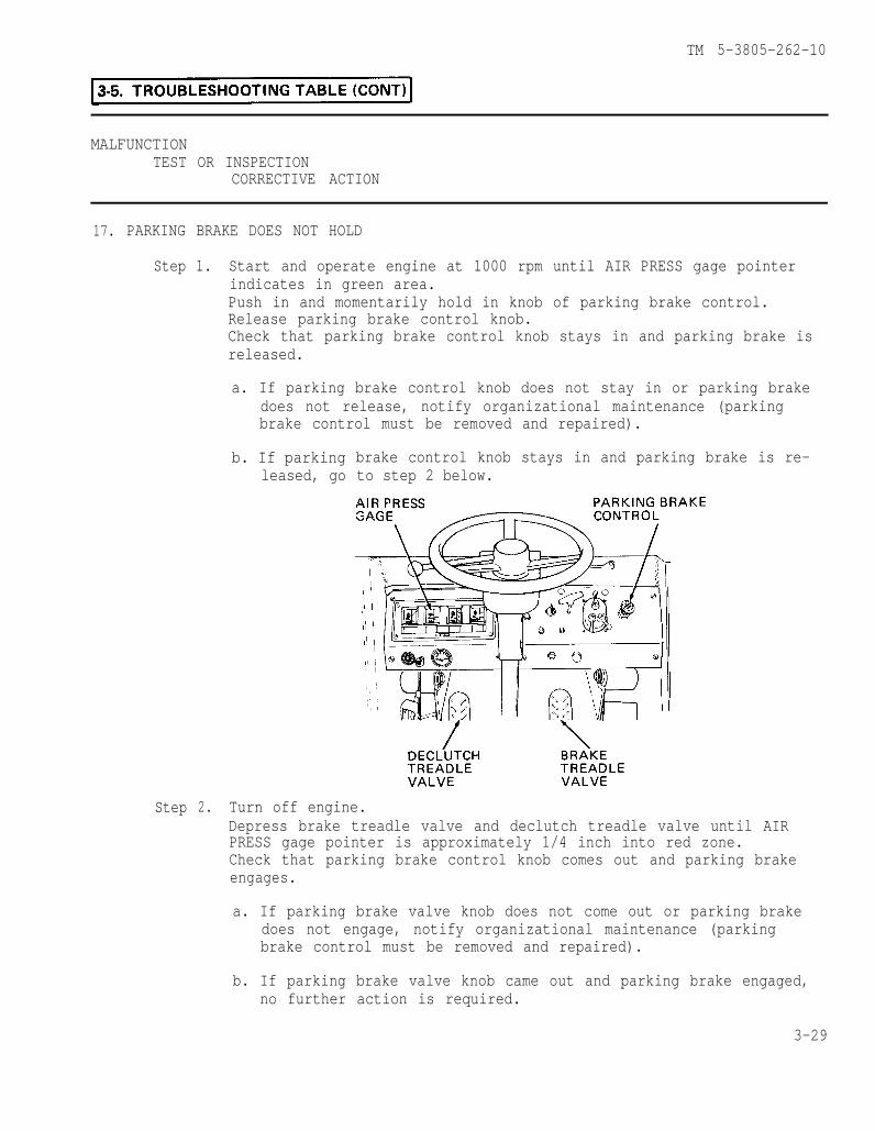
3-5.
TM 5-3805-262-10
MALFUNCTIONTEST OR INSPECTION
CORRECTIVE ACTION
17. PARKING BRAKE DOES NOT HOLD
Step 1. Start and operate engine at 1000 rpm until AIR PRESS gage pointerindicates in green area.Push in and momentarily hold in knob of parking brake control.Release parking brake control knob.Check that parking brake control knob stays in and parking brake isreleased.
a. If parking brake control knob does not stay in or parking brakedoes not release, notify organizational maintenance (parkingbrake control must be removed and repaired).
Step 2.
b. If parkingleased, go
brake control knob stays in and parking brake is re-to step 2 below.
Turn off engine.Depress brake treadle valve and declutch treadle valve until AIRPRESS gage pointer is approximately 1/4 inch into red zone.Check that parking brake control knob comes out and parking brakeengages.
a. If parking brake valve knob does not come out or parking brakedoes not engage, notify organizational maintenance (parkingbrake control must be removed and repaired).
b. If parking brake valve knob came out and parking brake engaged,no further action is required.
3-29

TM 5-3805-262-10
3-5. TROUBLESHOOTING TABLE (CONT)
MALFUNCTIONTEST OR INSPECTION
CORRECTIVE ACTION
18. SERVICE BRAKES UNEVEN OR ERRATIC
Check that tires are inflated to 40 psi.
a. If tires are not properly inflated, notify organizational main-tenance.
b. If tires are inflated to 40 psi, notify organizational mainte-nance.
19. LOW AIR PRESSURE (AIR PRESS GAGE INDICATES IN RED ZONE AND BUZZER SOUNDS)
Check if air reservoir drain valve is open.
a. If drain valve is
b. If drain valve is
20. TIRES WEAR RAPIDLY OR UNEVENLY
Check that tires are inflated
open, close it.
closed, notify organizational maintenance.
to 40 psi.
a. If tires are not properly inflated, notify organizational main-
tenance.
b. If tires are inflated to 40 psi, notify organizational mainte-nance.
3-30
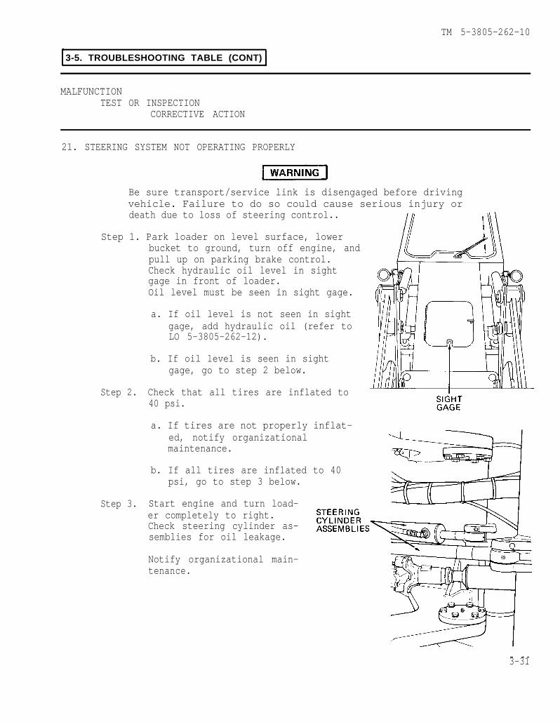
TM 5-3805-262-10
3-5. TROUBLESHOOTING TABLE (CONT)
MALFUNCTIONTEST OR INSPECTION
CORRECTIVE ACTION
21. STEERING SYSTEM NOT OPERATING PROPERLY
Be sure transport/service link is disengaged before drivingvehicle. Failure to do so could cause serious injury ordeath due to loss of steering control..
Step 1. Park loader on level surface, lowerbucket to ground, turn off engine, andpull up on parking brake control.Check hydraulic oil level in sightgage in front of loader.Oil level must be seen in sight gage.
a. If oil level is not seen in sightgage, add hydraulic oil (refer toLO 5-3805-262-12).
b. If oil level is seen in sightgage, go to step 2 below.
Step 2. Check that all tires are inflated to40 psi.
a. If tires are not properly inflat-ed, notify organizationalmaintenance.
b. If all tires are inflated to 40psi, go to step 3 below.
Step 3. Start engine and turn load-er completely to right.Check steering cylinder as-semblies for oil leakage.
Notify organizational main-tenance.
3-31

TM 5-3805-262-10
3-5. TROUBLESHOOTING TABLE (CONT)
MALFUNCTIONTEST OR INSPECTION
CORRECTIVE ACTION
22. LIFT ARMS DO NOT OPERATE PROPERLY
Step 1. Park loader on level surface, lowerbucket to ground, turn off engine, andpull up on parking brake control.Check hydraulic oil level in sightgage in front of loader.Oil level must be seen in sight gage.
a. If oil level is not seen in sightgage, add hydraulic oil (refer toLO 5-3805-262-12).
b. If oil level is seen in sightgage, go to step 2 below.
Step 2. Inspect bucket lift arm pivot pins andbushings for wear or damage.
a. If pivot pins or bushings are wornor damaged, notify organizationalmaintenance.
b. If pivot pins and bushings are not worn or damaged, go to step 3below.
Step 3. Check if bucket lift arm pivots are adequately lubricated.
a. If pivots are not adequately lubricated, lubricate (refer to LO5-3805-262-12) .
b. If pivots are adequately lubricated, notify organizational main-tenance.
3-32

TM 5-3805-262-10
3-5. TROUBLESHOOTING TABLE(CONT)
MALFUNTIONTEST OR INSPECTION
CORRECTIVE ACTION
23. RETURN-TO-DIG AND BUCKET HEIGHT CONTROL CIRCUITS DO NOT OPERATE
NOTE
Refer to pages 2-45 and 2-46 andtrol and return-to-dig control.
Step 1. Press top most 5 AMP circuitbreaker on right instrumentpane 1.
adjust bucket height con-
Start engine and place LIFT ARMcontrol lever in RAISE position.Check if 5 AMP circuit breakerbutton pops out when bucketreaches preselected height.
a. If circuit breaker buttonpopped when bucket reachedpreselected height, lowerbucket to ground.Notify organizational main-tenance (short circuit ex-ists in bucket height con-trol circuit).
b. If circuit breaker button did not pop, and desired dump heightwas not obtained, readjust bucket height control (page 2-45).
c. If circuit breaker button did not pop, go to step 2 below.
Step 2. With bucket at preselectedheight, put BUCKET control leverin CROWD and LIFT ARM controllever in FLOAT.Check if 5 AMP circuit breakerbutton pops out when bucketreaches desired digging orrollback angle.Put LIFT ARM control lever inNEUT. position when bucket is onground.
3-33
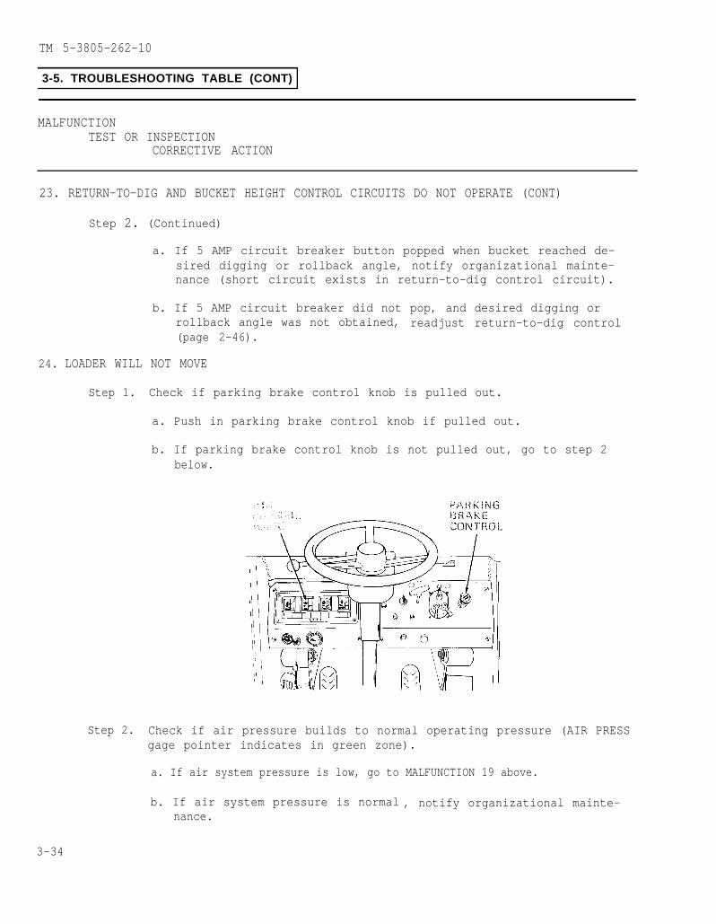
TM 5-3805-262-10
3-5. TROUBLESHOOTING TABLE (CONT)
MALFUNCTIONTEST OR INSPECTION
CORRECTIVE ACTION
23. RETURN-TO-DIG AND BUCKET HEIGHT CONTROL CIRCUITS DO NOT OPERATE (CONT)
Step 2. (Continued)
a. If 5 AMP circuit breaker button popped when bucket reached de-sired digging or rollback angle, notify organizational mainte-nance (short circuit exists in return-to-dig control circuit).
b. If 5 AMP circuit breaker did not pop, and desired digging orrollback angle was not obtained, readjust return-to-dig control(page 2-46).
24. LOADER WILL NOT MOVE
Step 1. Check if parking brake control knob is pulled out.
a. Push in parking brake control knob if pulled out.
b. If parking brake control knob is not pulled out, go to step 2below.
Step 2. Check if air pressure builds to normal operating pressure (AIR PRESSgage pointer indicates in green zone).
a. If air system pressure is low, go to MALFUNCTION 19 above.
b. If air system pressure is normal , notify organizational mainte-nance.
3-34

TM 5-3805-262-10
Section III. MAINTENANCE PROCEDURES
ParaIntroduction . . . . . . . .. . . . . . 3-6Inspection . . . . . . . . . . . . . . . 3-7
Fuel Injector Lines . . . . . . . . . . . 3-7aFuel Tank . . . . . . . . . . . . . 3-7bRadiator Assembly . . . . . . . . . . . . . 3-7cBattery Cables . .. . . . . . . . . 3-7dWiring Harnesses . . . . . . . . . . . . . . 3-7eDrive Shafts . . . . . . . . . . 3-7fLoader Bucket Assembly . . . . .. . 3-7gBucket Cutting EdgeAssemblies . . . . . . . . 3-7h
ParaClamshell Teeth Assemblies . . . . 3-7i
Servicing . . . . . . . . . . . . . . . . . . 3-8Air Cleaner . . . . . . . . . . . . . . 3-8aFuel Tank . . . . . . . . . . . . . . . . 3-8bAir Reservoir . . . . . . . . . . . . . . . . . 3-8cChecking Tires Air Pressure . . . 3-8dWindshield Washer Reservoir . . . 3-8e
Removal and Installation . . . . . . . 3-9Transport/Service
Link . . . . . . . . . . . . . . . . . 3-9aEngine Side Panels . . . . . . . . . . . . 3-9b
3-6. INTRODUCTION
This section provides maintenance procedures consisting of inspections and servicingof the various components and/or systems to be performed by the operator as autho-rized in the Maintenance Allocation Chart.
3-7. INSPECTION
a. Fuel Injector Lines.
(1) Unlock and remove engine front right side panel (under fender).
(2)
(3)
(4)
(5)
Start engine and operate at idleengine.
Inspect fuel injector lines atfuel injection pump and at fuelinjectors for fuel leaks.
If fuel leakage is observed,notify organizational mainte-nance.
Install and lock engine rightside panel.
speed for three minutes then turn off
3-35
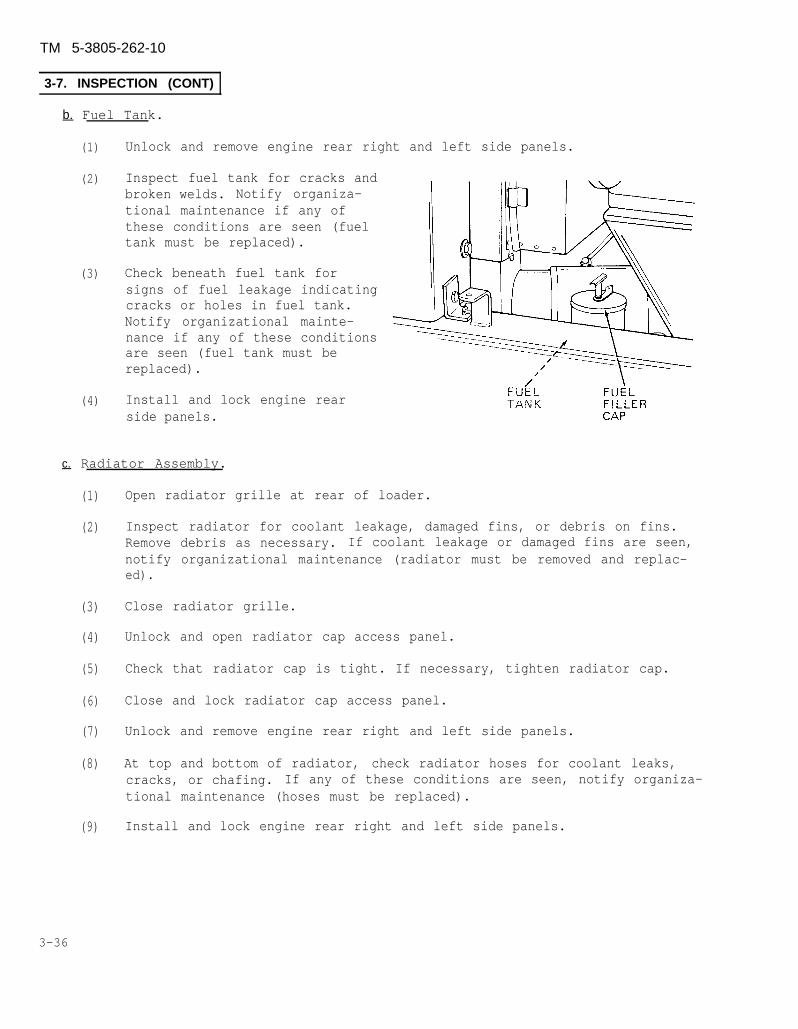
TM 5-3805-262-10
3-7. INSPECTION (CONT)
b. Fuel Tank.
(1)
(2)
(3)
(4)
Unlock and remove engine rear right and left side panels.
Inspect fuel tank for cracks andbroken welds. Notify organiza-tional maintenance if any ofthese conditions are seen (fueltank must be replaced).
Check beneath fuel tank forsigns of fuel leakage indicatingcracks or holes in fuel tank.Notify organizational mainte-nance if any of these conditionsare seen (fuel tank must bereplaced).
Install and lock engine rearside panels.
c. Radiator Assembly.
(1)
(2)
(3)
(4)
(5)
(6)
(7)
(8)
(9)
Open radiator grille at rear of loader.
Inspect radiator for coolant leakage, damaged fins, or debris on fins.Remove debris as necessary. If coolant leakage or damaged fins are seen,notify organizational maintenance (radiator must be removed and replac-ed).
Close radiator grille.
Unlock and open radiator cap access panel.
Check that radiator cap is tight. If necessary, tighten radiator cap.
Close and lock radiator cap access panel.
Unlock and remove engine rear right and left side panels.
At top and bottom of radiator, check radiator hoses for coolant leaks,cracks, or chafing. If any of these conditions are seen, notify organiza-tional maintenance (hoses must be replaced).
Install and lock engine rear right and left side panels.
3-36
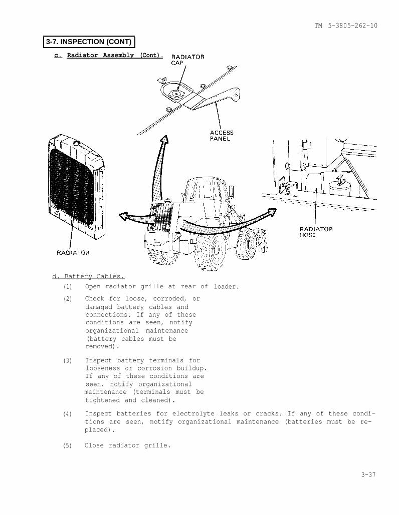
TM 5-3805-262-10
3-7. INSPECTION (CONT)
c. Radiator Assembly (Cont).
d. Battery Cables.
(1)
(2)
(3)
(4)
(5)
Open radiator grille at rear of
Check for loose, corroded, ordamaged battery cables andconnections. If any of theseconditions are seen, notifyorganizational maintenance(battery cables must beremoved).
Inspect battery terminals forlooseness or corrosion buildup.If any of these conditions areseen, notify organizationalmaintenance (terminals must betightened and cleaned).
loader.
Inspect batteries for electrolyte leaks or cracks. If any of these condi-tions are seen, notify organizational maintenance (batteries must be re-placed).
Close radiator grille.
3-37

TM 5-3805-262-10
3-7. lNSPECTION (CONT)
e. Wiring Harnesses. Inspect exposed wiring and connections for frayed or brokenwires and cracked or broken wire insulation. If any of these conditions are seen,notify organizational maintenance (wiring must be repaired).
f. Drive Shafts.
(1)
(2)
(3)
(4)
Start engine and operate at idle speed.
Turn loader fully right or left to gain accessto front drive shaft. Turn off engine.
Pull up on parking brake control knob to applyparking brake.
Grasp and try to rotate each drive shaft; checkfor movement indicating wear or damage. Checkthat universal joints mounting hardware are notloose. If any of these conditions are seen, no-tify organizational maintenance (drive shaftmust be removed and replaced).
g. Loader Bucket Assembly.
NOTE
If any of the following conditions are seen,notify organizational maintenance (must becorrected).
(1) Inspect blade and clam assembly forcracks, breaks, or broken welds.
(2) Check that hardware securing bucket pinsare tight and not loose.
(3) Check that hardware securing bucketclamshell cylinder assemblies pins aretight and not loose.
3-38
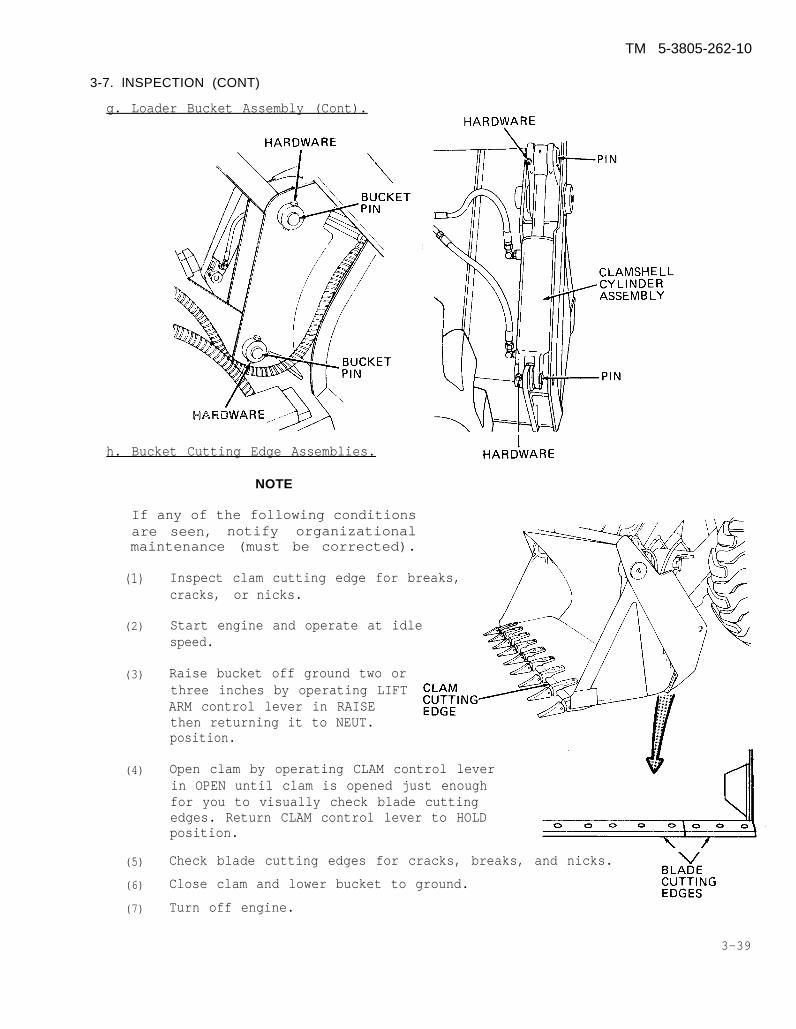
TM 5-3805-262-10
3-7. lNSPECTION (CONT)
g. Loader Bucket Assembly (Cont).
h. Bucket Cutting Edge Assemblies.
NOTE
If any of the following conditionsare seen, notify organizationalmaintenance (must be corrected).
(1)
(2)
(3)
(4)
(5)
(6)
(7)
three inches by operating LIFTARM control lever in RAISEthen returning it to NEUT.
Inspect clam cutting edge for breaks,cracks, or nicks.
Start engine and operate at idlespeed.
Raise bucket off ground two or
position.
Open clam by operating CLAM control leverin OPEN until clam is opened just enoughfor you to visually check blade cuttingedges. Return CLAM control lever to HOLDposition.
Check blade cutting edges for cracks, breaks, and nicks.
Close clam and lower bucket to ground.
Turn off engine.
3-39
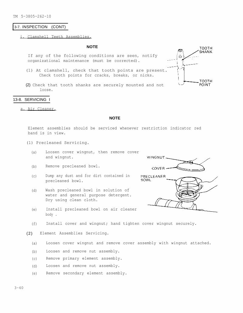
TM 5-3805-262-10
3-7. INSPECTION (CONT)
i. Clamshell Teeth Assemblies.
NOTE
If any of the following conditions are seen, notifyorganizational maintenance (must be corrected).
(1) At clamshell, check that tooth points are present.Check tooth points for cracks, breaks, or nicks.
(2) Check that tooth shanks are securely mounted and notloose.
13-8. SERVICING I
a. Air Cleaner.
NOTE
Element assemblies should be serviced whenever restriction indicator redband is in view.
(1) Precleaned Servicing.
(a) Loosen cover wingnut, then remove coverand wingnut.
(b) Remove precleaned bowl.
(c) Dump any dust and for dirt contained in precleaned bowl.
(d) Wash precleaned bowl in solution ofwater and general purpose detergent.Dry using clean cloth.
(e) Install precleaned bowl on air cleanerbody .
(f) Install cover and wingnut; hand tighten cover wingnut securely.
(2 ) Element Assemblies Servicing.
(a) Loosen cover wingnut and remove cover assembly with wingnut attached.
(b) Loosen and remove nut assembly.
(c) Remove primary element assembly.
(d) Loosen and remove nut assembly.
(e) Remove secondary element assembly.
3-40
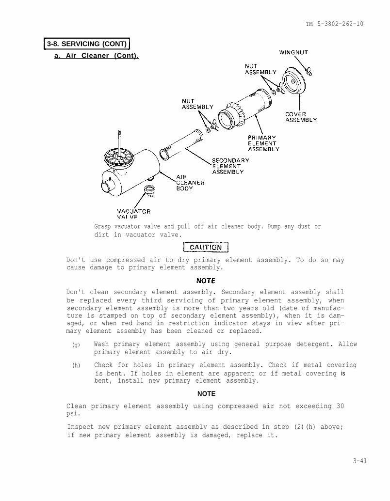
TM 5-3802-262-10
3-8. SERVICING (CONT)
a. Air Cleaner (Cont).
Grasp vacuator valve and pull off air cleaner body. Dump any dust ordirt in vacuator valve.
Don’t use compressed air to dry primary element assembly. To do so maycause damage to primary element assembly.
Don't clean secondary element assembly. Secondary element assembly shallbe replaced every third servicing of primary element assembly, whensecondary element assembly is more than two years old (date of manufac-ture is stamped on top of secondary element assembly), when it is dam-aged, or when red band in restriction indicator stays in view after pri-mary element assembly has been cleaned or replaced.
(g) Wash primary element assembly using general purpose detergent. Allowprimary element assembly to air dry.
(h) Check for holes in primary element assembly. Check if metal coveringis bent. If holes in element are apparent or if metal covering isbent, install new primary element assembly.
NOTE
Clean primary element assembly using compressed air not exceeding 30psi.
Inspect new primary element assembly as described in step (2)(h) above;if new primary element assembly is damaged, replace it.
3-41

TM 5-3805-262-10
3-8. SERVICING (CONT)
a. Air Cleaner (Cont).
(2) Element Assemblies Servicing (Cont).
(i) Clean vacuator valve using general purpose detergent. Dry using cleancloth.
(j) Using a clean cloth dampened with water and general purpose detergent,wipe inside of air cleaner body. Dry using clean, dry cloth.
(k) Reinstall vacuator valve on air cleaner body.
(l) Install secondary element assembly; secure using nut assembly.
(m) Install primary element assembly; secure using nut assembly.
(n) Install cover assembly and tighten cover wingnut securely.
(o) Press reset button on top of restriction indicator and check that redband disappears from view. Crank engine and check if restriction indi-cator red band comes into view. If red band is in view, repeat steps(2)(a) through (2)(e) above and replace secondary element assembly.
3-42
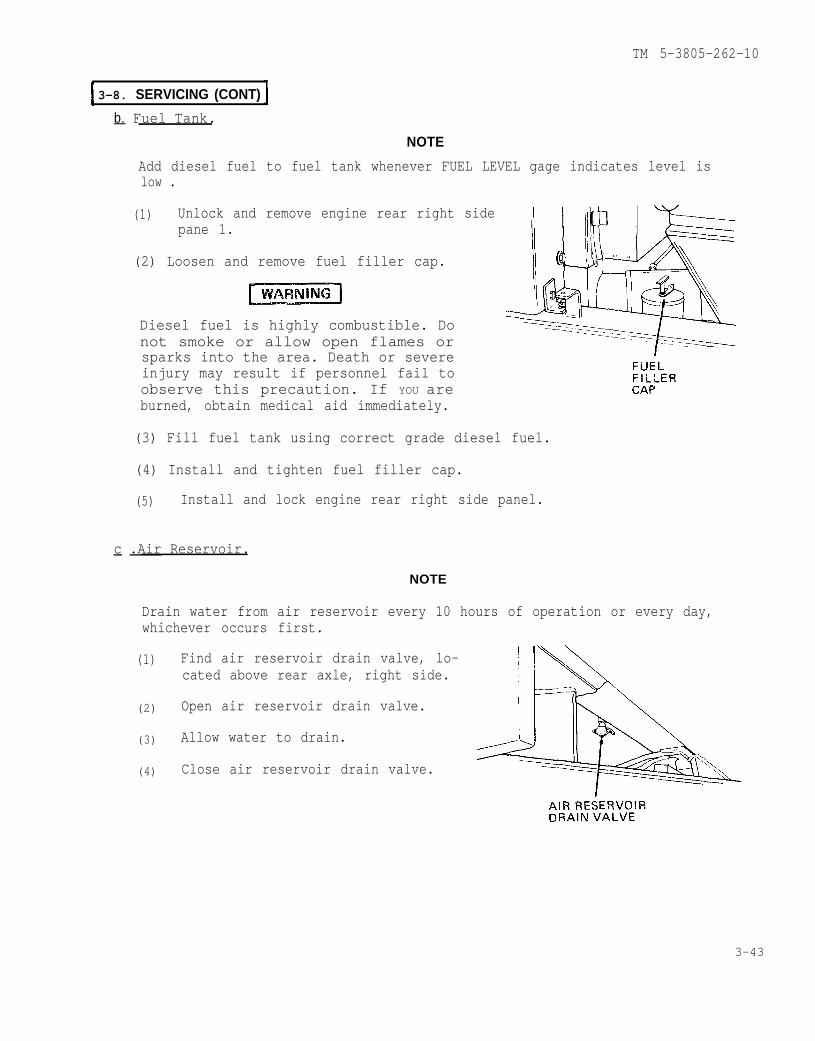
TM 5-3805-262-10
3-8. SERVICING (CONT)
b. Fuel Tank.
NOTE
Add diesel fuel to fuel tank whenever FUEL LEVEL gage indicates level islow .
(1) Unlock and remove engine rear right sidepane 1.
(2) Loosen and remove fuel filler cap.
Diesel fuel is highly combustible. Donot smoke or allow open flames orsparks into the area. Death or severeinjury may result if personnel fail toobserve this precaution. If YOU areburned, obtain medical aid immediately.
(3) Fill fuel tank using correct grade diesel fuel.
(4) Install and tighten fuel filler cap.
(5) Install and lock engine rear right side panel.
c .Air Reservoir.
NOTE
Drain water from air reservoir every 10 hours of operation or every day,whichever occurs first.
(1)
(2)
(3)
(4)
Find air reservoir drain valve, lo-cated above rear axle, right side.
Open air reservoir drain valve.
Allow water to drain.
Close air reservoir drain valve.
3-43
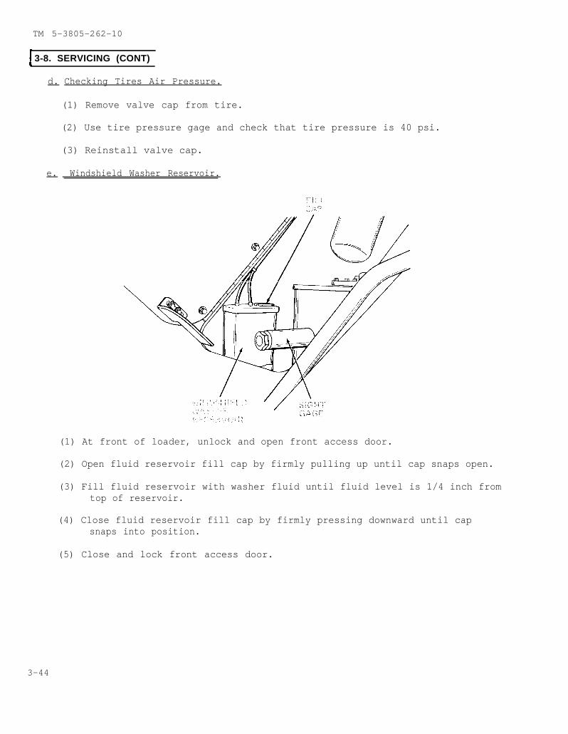
TM 5-3805-262-10
3-8. SERVICING (CONT)
d. Checking Tires Air Pressure.
(1) Remove valve cap from tire.
(2) Use tire pressure gage and check that tire pressure is 40 psi.
(3) Reinstall valve cap.
e. Windshield Washer Reservoir.
(1) At front of loader, unlock and open front access door.
(2) Open fluid reservoir fill cap by firmly pulling up until cap snaps open.
(3) Fill fluid reservoir with washer fluid until fluid level is 1/4 inch fromtop of reservoir.
(4) Close fluid reservoir fill cap by firmly pressing downward until capsnaps into position.
(5) Close and lock front access door.
3-44
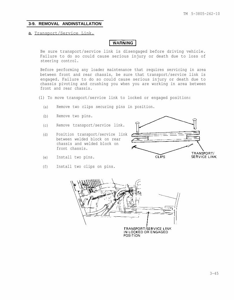
TM 5-3805-262-10
3-9. REMOVAL ANDINSTALLATION
a. Transport/Service Link.
Be sure transport/service link is disengaged before driving vehicle.Failure to do so could cause serious injury or death due to loss ofsteering control.
Before performing any loader maintenance that requires servicing in areabetween front and rear chassis, be sure that transport/service link isengaged. Failure to do so could cause serious injury or death due tochassis pivoting and crushing you when you are working in area betweenfront and rear chassis.
(1) To move transport/service link to locked or engaged position:
(a)
(b)
(c)
(d)
(e)
(f)
Remove two clips securing pins in position.
Remove two pins.
Remove transport/service link.
Position transport/service linkbetween welded block on rearchassis and welded block onfront chassis.
Install two pins.
Install two clips on pins.
3-45
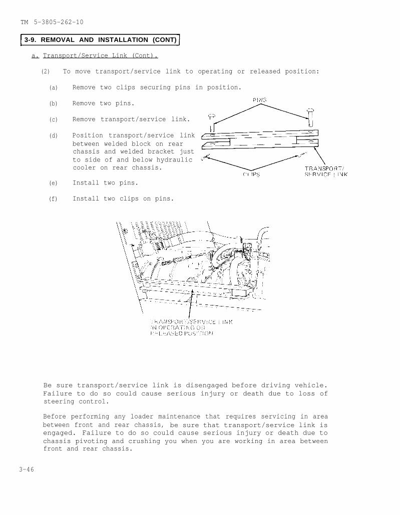
TM 5-3805-262-10
3-9. REMOVAL AND INSTALLATION (CONT)
a. Transport/Service Link (Cont).
(2) To move transport/service link to operating or released position:
(a)
(b)
(c)
(d)
(e)
(f)
Remove two clips securing pins in position.
Remove two pins.
Remove transport/service link.
Position transport/service linkbetween welded block on rearchassis and welded bracket justto side of and below hydraulic cooler on rear chassis.
Install two pins.
Install two clips on pins.
Be sure transport/service link is disengaged before driving vehicle.Failure to do so could cause serious injury or death due to loss ofsteering control.
Before performing any loader maintenance that requires servicing in areabetween front and rear chassis, be sure that transport/service link isengaged. Failure to do so could cause serious injury or death due tochassis pivoting and crushing you when you are working in area betweenfront and rear chassis.
3-46

TM 5-3805-262-10
3-9. REMOVAL AND INSTALLATION (CONT)
b. Engine Side Panels.
(1) Removal.
NOTE
Removal procedure for any one engine front or rear, right or left sidepanel is the same as described below.
(a) Unlock and remove lock securing engine side panel.
(b) Pull up on latch handle to disengage latch from engine side panelcatch.
(c) Grasp engine side panel handle and pull out bottom of engine sidepanel. Then, lift engine side panel up over spacers, washers, andcapscrews at upper edge of mounting area.
(d) Remove engine side panel from loader.
(2) Installation.
(a) Grasp enginetion.
side panel handle and raise engine side panel into posi-
(b) Using two holes at engine side panel upper edge, hang engine sidepanel on two spacers at upper edge of mounting area, then firmly pushbottom of engine side panel inward.
(c) Pull latch handle upward then engage latch with catch on engine sidepanel. Push down on latch handle to secure engine side panel.
(d) Install lock.
3-47


A-2.
A-3.
A-5.
TM 5-3805-262-10
APPENDIX A
REFERENCES
This appendix lists all forms and publications pertinent to the major item materialand associated equipment.
The following index should be consulted frequently for latest changes or revisionsand for new publications relating to material covered in this manual.
DA PAM 310-1 Consolidated Index of Army Publications and Forms
DA Form 2028DA Form 2028-2DA Form 2062DA Form 2402DA Form 2404DA Form 2406DA Form 2407DA Form 2408-9DA Form 2408-20DD Form 314SF 368
Recommended Changes to Publications and Blank FormsRecommended Changes to Equipment Technical PublicationsHand Receipt/Annex NumberExchange TagEquipment Inspection and Maintenance Work SheetMaterial Condition Status ReportMaintenance RequestEquipment Control RecordOil Analysis LogPreventive Maintenance Schedule and RecordQuality Deficiency Report
A-4. FIELD MANUALS
FM 9-207
FM 20FM 21-11FM 21-40FM 21-305FM 31-70FM 31-71FM 55-30FM 90-3FM 90-5FM 90-6FM 90-13
Operation and Maintenance of Ordnance Material in ColdWeather (O degrees F to -65 degrees F)
CamouflageFirst Aid for SoldiersNBC (Nuclear, Biological, and Chemical) DefenseManual for Wheeled Vehicle DriverBasic Cold Weather ManualNorthern OperationsDriver Selection and Training (Wheeled Vehicles)Desert OperationsJungle OperationsMountain OperationsRiver Crossing Operations
TM 5-3805-262-20 Organizational Maintenance: Loader Scoop Type MW24CTM 5-3805-262-24P Organizational, Direct Support, and General Support Mainte-
nance Repair Parts and Special Tools List: Loader, SCOOPType, MW24C
A-1

TM 5-3805-262-10
A-5. TECHNICAL MANUALS (CONT)
TM 5-3805-262-34 Direct Support and General Support Maintenance: Loader,Scoop Type MW24C
TM 9-6140-200-14 Operation and Organizational Maintenance Manual for Lead AcidStorage Batteries
TM 9-8000 Principles of Automotive VehiclesTM 740-90-1 Administrative Storage of EquipmentTM 750-244-6
. .Procedures for Destruction of Tank Automotive Equipment
to Prevent Enemy UseTM 750-254 Cooling Systems: Tactical Vehicles
A-6. TECHNICAL BULLETINS
TB 9-2300-422-20 Security of Tactical Wheeled VehiclesTB 43-0001-39 Equipment Improvement Report and Maintenance DigestTB 750-651 Use of Antifreeze Solutions, and Cleaning Compounds in En-
gine Cooling SystemsTB 43-0210 NonAeronautical Equipment Army Oil Analysis Program
A-7. OTHER PUBLICATIONS
DA PAM 738-750 The Army Maintenance Management System (TAMMS)LO 5-3805-262-12 Lubrication Order: Loader, Scoop Type, MW24CTM 5-3805-262-10HR Hand Receipt: Loader, SCOOp Type, MW24C
A-8. ARMY REGULATIONS
AR 310-2 Identification and Distribution of DA Publications andIssue of Agency and Command Administration Publications
AR 310-25 Dictionary of United States Army TermsAR 385-40 Accident Reporting and RecordsAR 385-55 Prevention of Motor Vehicle Accidents
A-2

B-1.
TM 5-3805-262-10
APPENDIX B
COMPONENTS OF END ITEM (COEI) AND BASICISSUE ITEMS (BII) LISTS
Section I. INTRODUCTION
This appendix lists components of end item and basic issue items for the MW24Cloader to help you inventory items required for safe and efficient operation.
B-2. GENERAL
The Components of End Item and Basic Issue Items Lists are divided into thefollowing sections:
a. Section II - Components of End Item. This listing is for informationalpurposes only, and is not authority to requisition replacements. These items arepart of the end item, but are removed and separately packaged for transportation orshipment. As part of the end item, these items must be with the end item whenever itis issued or transferred between property accounts. Illustrations are furnished toassist you in identifying the items.
b. Section III -Basic Issue Items. These are the minimum essential itemsrequired to place the MW24C loader in operation, to operate it, and to performemergency repairs. Although shipped separately packaged BII must be with the loaderduring operation and whenever it is transferred between property accounts. Theillustrations will assist you with hard-to-identify items. This manual is yourauthority to request/requisition replacement BII, based on TOE/MTOE authorization ofthe end item.
B-3. EXPLANATION OFCOLUMNS
The following provides an explanation of columns found in the tabular listings:
a. Column 1 - Illustration Number (Illus number). This column indicates thenumber of the illustration in which the item is shown.
b. Column 2 -National Stock Number. Indicates the National stock numberassigned to the item and will be used for requisitioning purposes.
c. Column 3 - Description. Indicates the National item name and, if required, aminimum description to identify and locate the item. The last linefor each item indicates the Federal Supply Code for Manufacturer (FSCM) inparentheses followed by the part number.
d. Column 4 - Unit of Measure (U/M). Indicates the measure used in performingthe actual operational/maintenance function. This measure is expressed by atwo-character alphabetical abbreviation (e.g., ea, in, pr).
e. Column 5 - Quantity Required (Qty rqr). Indicates the quantity of the itemauthorized to be used with/on the equipment.
B-1
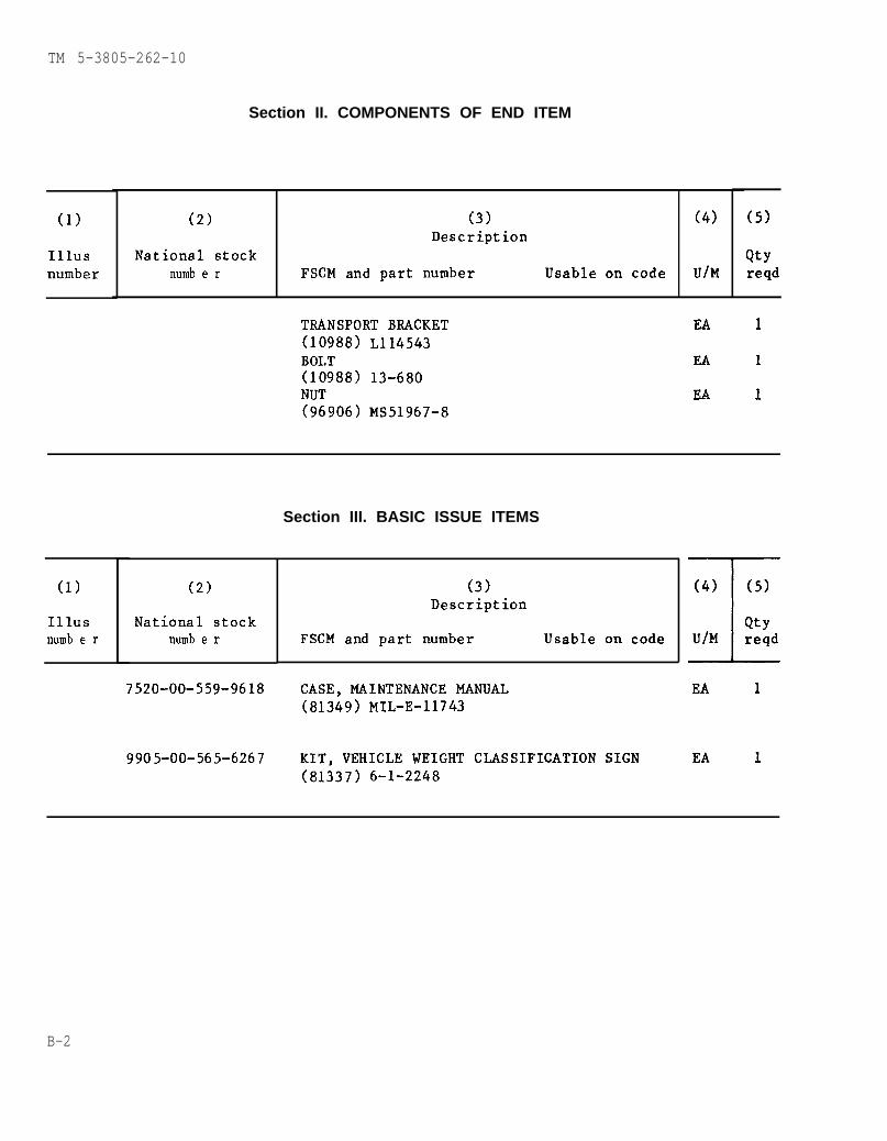
TM 5-3805-262-10
(1)
Illusnumber
Section II. COMPONENTS OF END ITEM
(2)
National stocknumb e r
(3)Description
FSCM and part number Usable on code
(4)
U/M
(5)
Qtyreqd
TRANSPORT BRACKET(10988) L114543BOLT(10988) 13-680NUT(96906) MS51967-8
EA
EA
EA
1
1
1
(1)
Illusnumb e r
(2)
National stocknumb e r
7520-00-559-9618
9905-00-565-6267
Section III. BASIC ISSUE ITEMS
(3)Description
FSCM and part number Usable on code
CASE, MAINTENANCE MANUAL(81349) MIL-E-11743
KIT, VEHICLE WEIGHT CI.JWSIFICATION SIGN(81337) 6-1-2248
J_QtyU/M reqd
EA 1
EA 1
B-2

TM 5-3805-262-10
APPENDIX C
ADDITIONAL AUTHORIZATION LIST (AAL) ITEMS
Section I. INTRODUCTION
This appendix lists additional items you are authorized for support of the MW24Cloader.
C-2. GENERAL
This list identifies items that do not have to accompany the MW24C loader and that
do not have to be turned in with it. These items are all authorized to you by CTA,MTOE, TDA, or JTA.
C-3. EXPLANATION OF LISTING
National stock numbers, descriptions, and quantities are provided to help youidentify and request the additional items you require to support the equipment.
Section II. ADDITIONAL AUTHORIZATION LIST
(1) (2) (3) (4)National Description Qty.Stock U/MNumber
auth.FSCM and Part Number Usable on code
4210-00-889-2221
4910-00-204-3170
4930-00-253-2478
5120-00-223-7397
5120-00-234-8913
5120-00-278-1283
5120-00-449-8083
5120-00-895-9568
5120-00-895-9570
5120-00-224-3153
5120-00-224-3154
EXTINGUISHER, FIRE(58536) A-A-393
GAGE, TIRE PRESSURE(53477) 7188BHLUBRICATING GUN, HAND(36251 ) 1142PLIERS, SLIP JOINT(56161) 1051 0983SCREWDRIVER, CROSS TIP #2(96906) MS15224-5SCREWDRIVER, FLAT TIP 6 INCHES(19207) 4151104WRENCH, ADJUSTABLE, 10 INCHES(11083) 1B7536WRENCH, BOX AND OPEN END 7/16 INCH
(81348) GGG-W-645WRENCH, BOX AND OPEN END 9/16 INCH(81348) GGG-W-645WRENCH, BOX, 3/8 AND 7/16 INCH(47805) WBG1214WRENCH, BOX, 1/2 AND 9/16 INCH(18949) G2042
EA.
EA
EA
EA
EA
EA
EA
EA
EA
EA
EA
1
1
1
1
1
1
1
1
1
1
1
C-1

D-1.
TM 5-3805-262-10
APPENDIX D
EXPENDABLE/DURABLE SUPPLIES AND MATERIALS LIST
Section I. INTRODUCTION
This appendix lists expendable/durable supplies and materials you will need tooperate and maintain the MW24C loader. These items are authorized to you by CTA50-970, Expendable Items (Except Medical, Class V, Repair Parts, and HeraldicItems).
D-2. EXPLANATION OFCOLUMNS
a. Column 1 - Item Number. This number is assigned to each entry in the listing.
b. Column 2 - Level. This column identifies the lowest level of maintenance thatrequires the listed item. The symbol designation is as follows:
c . . . . . . . . . . . . . . Operator/Crew
c. Column 3 - National Stock Number. This is the National stock number assignedto the item; use it to request or requisition the item.
d. Column 4 - Description. Indicates the Federal item name and, if required, adescription to identify the item. The last line for each item indicates the FederalSupply Code for Manufacturer (FSCM) in parentheses followed by the part number.
e. Column 5 - Unit of Measure (tJ/M). Indicates the measure used in performingthe actual maintenance function. This measure is expressed by an alphabeticalabbreviation (QT, GAL.). If the unit of measure differs from the unit of issue,requisition the lowest unit of issue that will satisfy your requirements.
D-1
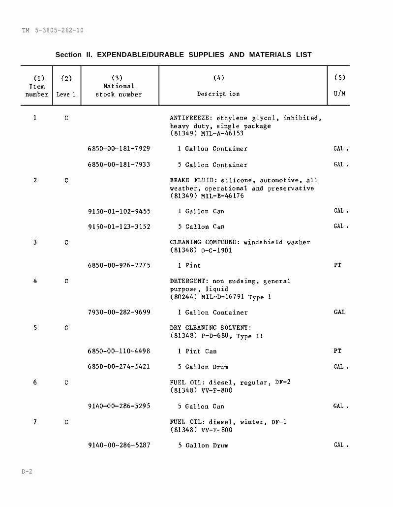
TM 5-3805-262-10
Section II. EXPENDABLE/DURABLE SUPPLIES AND MATERIALS LIST
(1) (2) (3) (4) (5)Item National
number Leve 1 stock number Descript ion U/M
1 c
2
3
4
5
6
7
6850-00-181-7929
6850-00-181-7933
c
9150-01-102-9455
9150-01-123-3152
c
6850-00-926-2275
c
7930-00-282-9699
c
6850-00-110-4498
6850-00-274-5421
c
9140-00-286-5295
c
9140-00-286-5287
ANTIFREEZE: ethylene glycol, inhibited,heavy duty, single package(81349) MIL-A-46153
1 Gallon Container
5 Gallon Container
BRAKE FLUID: silicone, automotive, allweather, operational and preservative(81349) MIL-B-46176
1 Gallon Can
5 Gallon Can
CLEANING COMPOUND: windshield washer(81348) O-C-1901
1 Pint
DETERGENT: non sudsing, generalpurpose, liquid(80244) MIL-D-16791 Type 1
1 Gallon Container
DRY CLEANING SOLVENT:(81348) P-D-680, Type II
1 Pint Can
5 Gallon Drum
FUEL OIL: diesel,(81348) VV-F-800
5 Gallon Can
FUEL OIL: diesel,(81348) VV-F-800
5 Gallon Drum
regular, DF-2
winter, DF-1
GAL .
GAL .
GAL .
GAL .
PT
GAL
PT
GAL .
GAL .
GAL .
D-2

TM 5-3805-262-10
Section II. EXPENDABLE/DURABLE SUPPLIES AND MATERIALS LIST (CONT)
(1) (2) (3) (4) (5)Item National
number Level stock number Description U/M
8
9
10
11
12
13
c
c
c
c
c
c
9140-00-286-5282
9150-00-935-1017
9150-00-190-0904
9150-00-035-5392
9150-01-035-5396
9150-00-231-6689
9150-00-402-4478
9150-00-402-2372
9150-00-189-6727
9150-00-186-6618
FUEL OIL: diesel, arctic, DF-A(81348) VV-F-800
5 Gallon Drum
GREASE: automotive and artillery(81349) MIL-G-10924
14 Ounce Cartridge
1-3/4 Pound Can
LUBRICATING OIL: gear, multipurpose,GO 85/140(81349) MIL-L-2105
1 Quart Can
5 Gallon Can
LUBRICATING OIL: general purpose,preservative, PL-S(81348) VV-L-800
1 Quart Can
LUBRICATING OIL: internal combustionengine, arctic, OEA(81349) MIL-L-46167
1 Quart
5 Gallon Drum
LUBRICATING OIL: internal combustionengine, tactical service, OE/HDO 10(81349) MIL-L-2104
1 Quart Can
5 Gallon Drum
GAL.
Oz
LB
QT
GAL .
QT
QT
GAL .
Qt
GAL .
D-3
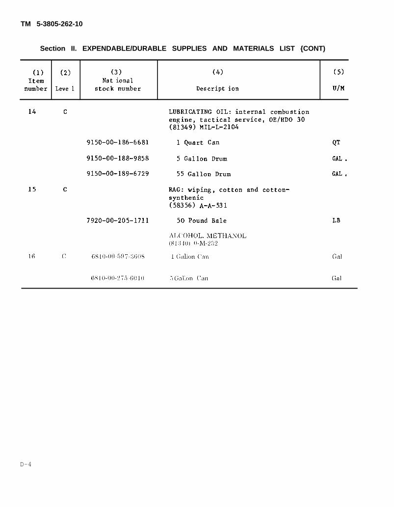
TM 5-3805-262-10
Section II. EXPENDABLE/DURABLE SUPPLIES AND MATERIALS LIST {CONT)
(1) (2) (3) (4) (5)Item Nat ional
number Leve 1 stock number Descript ion U/M
14 c LUBRICATING OIL: internal combustionengine, tactical service, OE/HDO 30
15
16
c
(8i349) MIL-L-2104
9150-00-186-6681 1 Quart Can
9150-00-188-9858 5 Gallon Drum
9150-00-189-6729 55 Gallon Drum
RAG: wiping, cottonsynthenic(58356) A-A-531
7920-00-205-1711 50 Pound Bale
QT
GAL .
GAL .
and cotton-
LB
ALCOHOL,METHANOL(81:140) ()-M-?:]?
c (;810-()()-5!)7 -:1(;()8 1 (;allon (’an Gal
6810-00-2756010 5 Crallon Can Gal
D-4
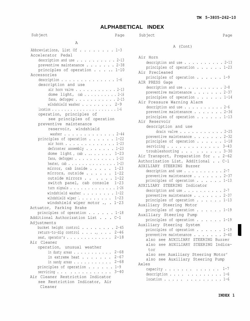
Subject
ALPHABETICAL INDEXPage Subject
A
Abbreviations, List Of . . . . . . . . 1-3Accelerator Pedal
description and use . . . . . . . . . . 2-13preventive maintenance . . . . . . . 2-38principles of operation . . . .. 1-10
Accessoriesdescription . . . . . . . . . . . . . . 1-6description and use
air horn valve . . . . . . . . . . . 2-13dome light, cab . . . . . . . . . . 2-16fans, defogger . . . . . . . . . . . 2-15
. .windshield washer . . . . . . . . 2-9
location . . . . . . . . . . . . . . . . . . . . . 1-6operation, principles of
see principles of operationpreventive maintenance
reservoir, windshieldwasher . . . . . . . . . . . . . 2-44
principles of operation . . . . . . 1-22air horn . . . . . . . . . . . . . 1-23defroster assembly . . . . . . . 1-23dome light , cab . .. . . . . . 1-23fans, defogger . . . . . . . . . . . 1-23heater, cab . . . . . . . . . . . . . . 1-23.mirror, cab inside . . . . . 1-23.mirrors, outside . . . . . . 1-22outside mirrors . . . . . . 1-22switch panel, cab console 1-23turn signals . . . . . . . . . . . . . 1-26windshield washer . . . . . . . . 1-22
. . .windshield wiper . . . . . . . . . 1-23windshield wiper motor ., . 1-23
Actuator, Parking Brakeprinciples of operation . . . . . . 1-18
Additional Authorization List . . . C-1Adjustments
bucket height control . . . . . . . . 2-45return-to-dig control . . . ., . . . 2-46seat, operator’s . . . . . . . . . . . . . 2-18
Air Cleaneroperation, unusual weather
in dusty areas . . . . . . . . . . . 2-68in extreme heat . . . . . . . 2-67in sandy areas . . . . . . . . . . . 2-68
principles of operation . . . . . . 1-9servicing . . . . . . . . . . . . . . 3-40
Air Cleaner Restriction Indicatorsee Restriction Indicator, AirCleaner
TM 5-3805-262-10
Page
A (Cont)
Air Horndescription and use . . . . . . . . . . 2-13principles of operation . . . . . . 1-23
Air Precleanedprinciples of operation . . . . . . 1-9
AIR PRESS Gagedescription and use . . . . . . . . . . 2-8preventive maintenance . . . . . . . 2-37principles of operation . . . . . . 1-14
Air Pressure Warning Alarmdescription and use . . . . . . . . . . 2-6preventive maintenance . . . . . . . 2-36principles of operation . . . . . . 1-13
Air Reservoirdescription and use
drain valve . . . . . . . . . . . 2-25preventive maintenance . . . . . . . 2-32principles of operation . . . . . . 1-18servicing . . . . . . . . . . . . . 3-43troubleshooting . . . . . . . . . 3-30
Air Transport, Preparation for . . 2-62Authorization List, Additional . . C-1AUXILIARY STEERING Buzzer
description and use . . . . . . . . . . 2-7preventive maintenance . . . . . . . 2-37principles of operation . . . . . . 1-13
AUXILIARY STEERING Indicatordescription and use . . . . . . . . . . 2-7preventive maintenance . . . . . . . 2-37principles of operation . . . . . . 1-13
Auxiliary Steering Motorprinciples of operation . . . . . . 1-19
Auxiliary Steering Pumpprinciples of operation . . . . . . 1-19
Auxiliary Steering Systemprinciples of operation . . . . . . 1-19preventive maintenance . . . . . . . 2-40also see AUXILIARY STEERING Buzzeralso see AUXILIARY STEERING Indica-toralso see Auxiliary Steering Motor’also see Auxiliary Steering Pump
Axlescapacity . . . . . . . . . . . . . 1-7description . . . . . . . . . . . . . 1-6location . . . . . . . . . . . . . . 1-6
INDEX 1

TM 5-3805-262-10
ALPHABETICAL INDEX (CONT)Subject Page Subject
B
Back-up Alarmpreventive maintenance . . . . . . . 2-38principles of operation . . . . . . 1-25
Basic Issue Items . . . . . . . . . . . . . . . B-2Batteries
preventive maintenance . . . . . . . 2-43principles of operation . . . . . . 1-15troubleshooting . . . . . . . . . . . . . . 3-23
Battery CablesInspection . . . .. . . ... . . . . 3-37preventive maintenance . . . . . . . 2-33principles of operation . . . . . . 1-15
Black Out Driving Lamppreventive maintenance . . . . . . . 2-36principles of operation . . . . . . 1-12
Black Out Lights Wiring HarnessInspection . . . . . .. . . . . . . . . 3-38preventive maintenance . . . . . . . 2-33principles of operation . . . . . . 1-16
Black Out Stop Light-Tail Lightpreventive maintenance . . . . . . . 2-36principles of operation . . . . . . 1-12
BRAKE ENGAGED Warning Indicatordescription and use . . . . . . . . . . 2-7preventive maintenance . . . . . . . 2-36principles of operation . . . . . . 1-13
Brake Treadle Valvedescription and use . . . . . . . . . . 2-13principles of operation . . . . . . 1-18
Brake Systemcold weather, operation in . . . 2-66description . . . . . . . . . . . . . . . . . . 1-5description and use . . . . . . . . . . 2-6
air reservoir drain valve 2-25brake treadle valve . . . . . . 2-13parking brake valve . . . . . . 2-6
location .. OO. .OO . . . . . ..O . . . . . 1-5operation, principles of
see principles of operationpreventive maintenance
air reservoir . . . . . . . . . . . . 2-32parking brake valve . . . . . . 2-38service brakes . . . . . . . . . . . 2-38
principles of operation . . . . . . 1-18actuator, parking brake . . 1-18air reservoir . . . . . . . . . . . . 1-18brake treadle valve . . . . . . 1-18parking brake . . . . . . . . . . . . 1-18
Page
B (Cont)
Brake System (cont)principles of operation (cont)
parking brake valve . . . . . . 1-18service brakes . . . . . . . . . . . 1-18
servcing, air reservoir . . . . . 3-43troubleshooting . . . . . . . . . . . . . . 3-29
Bucket Assembly, Loaderbucket capacity . . . . . . . . . . . . . . 1-8bucket width . . .. . . . . . . . . . 1-8.Inspection . . . . . . . . . . . . . . 3-38preventive maintenance . . . . . . . 2-34
clamshell teeth assemblies 2-35cutting edge assemblies . . 2-35
principles of operation . . . . . . 1-26Bucket Clamshell Cylinder Assemblies
principles of operation . . . . . . 1-24BUCKET Control Lever
description and use . . . . . . . . . . 2-19preventive maintenance . . . . . . . 2-39principles of operation . . . . . . 1-24
Bucket Cutting Edge Assemblies.
inspection . . . . . . . . . . . . . . . . . . . 3-39preventive maintenance . . . . . . . 2-35
Bucket Height Controladjustment . . . . . . . . . . .. ..description and use . . . . . . . . . .principles of operation . . . . . .troubleshooting . . . . . . . . . . . . . .
Bucket Level Indicatordescription and use . . . . . . . . . .
Bucket Lift Arm Assembliesoperation in dusty areas . . . . .operation in sandy areas . . . . .principles of operation . . . . . .troubleshooting . . . . . . . . . . . . . .
Bucket Pivot Assembliesoperation in dusty areas. . . . . . . .operation in sandy areas . . . . .preventive maintenance . . . . . . .principles of operation . . . . . .troubleshooting . .. . . . . . . .
2-452-201-243-33
2-20
2-682-681-263-32
2-682-682-291-263-32
Bucket Tilt Cylinder Assembliesprinciples of operation . . . . . . 1-24
c
Cabdescription . . . . . . . . . . . . . . 1-6
INDEX 2
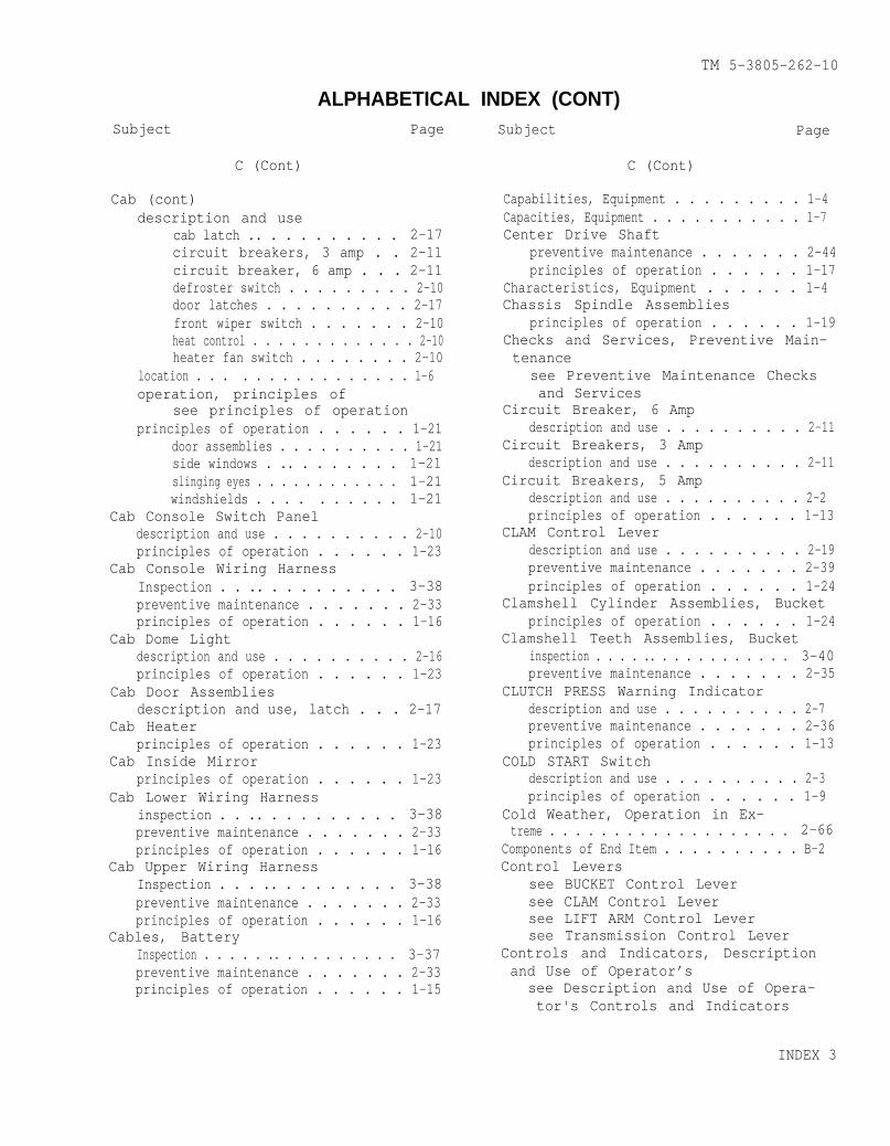
TM 5-3805-262-10
ALPHABETICAL INDEX (CONT)Subject
C (Cont)
Cab (cont)description and use
cab latch .. . . . . . . . . . 2-17circuit breakers, 3 amp . . 2-11circuit breaker, 6 amp . . . 2-11defroster switch . . . . . . . . . 2-10door latches . . . . . . . . . . 2-17front wiper switch . . . . . . . 2-10heat control . . . . . . . . . . . . . 2-10heater fan switch . . . . . . . . 2-10
location . . . . . . . . . . . . . . . . 1-6operation, principles of
see principles of operationprinciples of operation . . . . . . 1-21
door assemblies . . . . . . . . . . 1-21side windows . .. . . . . . . . 1-21slinging eyes . . . . . . . . . . . . 1-21windshields . . . . . . . . . . 1-21
Cab Console Switch Paneldescription and use . . . . . . . . . . 2-10principles of operation . . . . . . 1-23
Cab Console Wiring HarnessInspection . . .. . . . . . . . . . 3-38preventive maintenance . . . . . . . 2-33principles of operation . . . . . . 1-16
Cab Dome Lightdescription and use . . . . . . . . . . 2-16principles of operation . . . . . . 1-23
Cab Door Assembliesdescription and use, latch . . . 2-17
Cab Heaterprinciples of operation . . . . . . 1-23
Cab Inside Mirrorprinciples of operation . . . . . . 1-23
Cab Lower Wiring Harnessinspection . . .. . . . . . . . . . 3-38preventive maintenance . . . . . . . 2-33principles of operation . . . . . . 1-16
Cab Upper Wiring HarnessInspection . . . .. . . . . . . . . 3-38
Page Subject Page
preventive maintenance . . . . . . . 2-33principles of operation . . . . . . 1-16
Cables, BatteryInspection . . . . . .. . . . . . . . . . 3-37preventive maintenance . . . . . . . 2-33principles of operation . . . . . . 1-15
C (Cont)
Capabilities, Equipment . . . . . . . . . 1-4Capacities, Equipment . . . . . . . . . . . 1-7Center Drive Shaft
preventive maintenance . . . . . . . 2-44principles of operation . . . . . . 1-17
Characteristics, Equipment . . . . . . 1-4Chassis Spindle Assemblies
principles of operation . . . . . . 1-19Checks and Services, Preventive Main-tenance
see Preventive Maintenance Checksand Services
Circuit Breaker, 6 Ampdescription and use . . . . . . . . . . 2-11
Circuit Breakers, 3 Ampdescription and use . . . . . . . . . . 2-11
Circuit Breakers, 5 Ampdescription and use . . . . . . . . . . 2-2principles of operation . . . . . . 1-13
CLAM Control Leverdescription and use . . . . . . . . . . 2-19preventive maintenance . . . . . . . 2-39principles of operation . . . . . . 1-24
Clamshell Cylinder Assemblies, Bucketprinciples of operation . . . . . . 1-24
Clamshell Teeth Assemblies, Bucketinspection . . . . .. . . . . . . . . . . . 3-40preventive maintenance . . . . . . . 2-35
CLUTCH PRESS Warning Indicatordescription and use . . . . . . . . . . 2-7preventive maintenance . . . . . . . 2-36principles of operation . . . . . . 1-13
COLD START Switchdescription and use . . . . . . . . . . 2-3principles of operation . . . . . . 1-9
Cold Weather, Operation in Ex-treme . . . . . . . . . . . . . . . . . . . 2-66
Components of End Item . . . . . . . . . . B-2Control Levers
see BUCKET Control Leversee CLAM Control Leversee LIFT ARM Control Leversee Transmission Control Lever
Controls and Indicators, Descriptionand Use of Operator’s
see Description and Use of Opera-tor's Controls and Indicators
INDEX 3
TM 5-3805-262-10
Subject
C (Cont)
ALPHABETICAL INDEX (CONT)
SubjectPage Page
CONV TEMP Gagedescription and use . . . . . . . . . . 2-8preventive maintenance . . . . . . . 2-37principles of operation . . . . . . 1-14
Cooling Systemcapacity . . . . . . . . . . . . . . . . . . . . . 1-7cold weather protection . . . . . . 1-7description . . . . . . . . . . . . . . . . . . 1-4Inspection . . . . . . . . . . . . . . . . . . . 3-36location . . . . . . . . . . . . . . . . . . . . . 1-4operation
in dusty areas . . . . . . . . . . . 2-68in extreme cold . . . . . . . . . . 2-66in extreme heat . . . . . . . . . . 2-67in sandy areas . . . . . . . . . . . 2-68
operation, principles ofsee principles of operation
preventive maintenance . . . . . . . 2-31principles of operation . . . . . . 1-10
radiator . . . . . . . . . . . . . . . 1-10WATER TEMP gage . . . . . . . . . . 1-10
radiatorpreventive maintenance . . . 2-31principles of operation . . 1-10
troubleshooting . . . . . . . . . . . . . . 3-20WATER TEMP gage
description and use . . . . . . 2-8principles of operation . . 1-10
Cutting Edge Assemblies, BucketInspection . . . . . . . . . . . . . . . . . . . 3-39preventive maintenance . . . . . . . 2-35
Cylinder Assembliessee Bucket Clamshell Cylinder As-semblies
see Bucket Tilt Cylinder Assembliessee Lift Arm Cylinder Assembliessee Steering Cylinder Assemblies
D
Decals and Identification Plates 2-62Declutch Treadle Valve
description and use . . . . . . . . . . 2-12principles of operation . . . . . . 1-17
Defogger Fansdescription and use . . . . . . . . . . 2-15principles of operation . . . . . . 1-23
D (Cont)
Defroster Assemblyprinciples of operation . . . . . . 1-23
Defroster Switchdescription and use . . . . . . . . . . 2-10
Description and Use of Operator’s Con-trols and Indicators . . . . . . . . . . . 2-1
accelerator pedal . . . . . . . . . . . . 2-13air horn valve . . . . . . . . . . . . . . . 2-13air reservoir drain valve . . . . 2-25brake treadle valve . . . . . . . . . . 2-13cab console switch panel . . . . . 2-10
circuit breakers . . . . . . . . . 2-11defroster switch . . . . . . . . . 2-10front wiper switch . . . . . . . 2-10heat control . . . . . . . . . . . . . 2-10heater fan switch . . . . . . . . 2-10
control levers, loader . . . . . . . 2-19BUCKET control lever . . . . . 2-19CLAM control lever . . . . . . . 2-19LIFT ARM control lever . . . 2-19
controls, loader . . . . . . . . . . . . . 2-20bucket height control . . . . 2-20bucket level indicator . . . 2-20return-to-dig control . . . . 2-20selector gage . . . . . . . . . . . . 2-21
dome light switch, cab . . . . . . . 2-16engine oil level dipstick andfill . . . . . . . . . . . . . . . . . . . . . . . . 2-23
fans, defogger . . . . . . . . . . . . . . . 2-15hazard control . . . . . . . . . . . . . . . 2-14hourmeter . . . . . . . . . . . . . . . . . . . . 2-22hydraulic reservoir fill . . . . . 2-24latches, cab door . . . . . . . . . . . . 2-17left instrument panel . . . . . . . . 2-7
AIR PRESS gage . . . . . . . . . . . 2-8AUXILIARY STEERING buzzer andindicator . . . . . . . . . . . . . . . 2-7
BRAKE ENGAGED warning indica-tor . . . . . . . . . . . . . . . . . . . . . 2-7
CLUTCH PRESS warning indica-tor . . . . . . . . . . . . . . . . . . . . . 2-7
CONVTEMP gage . . . . . . . . . . . 2-8FUEL LEVEL gage . . . . . . . . . ● 2-8OIL PRESS warning indica-tor . . . . . . . . . . . . . . . . . . . . . 2-7
Voltmeter gage . . . . . . . . . . . 2-8WATER TEMP gage . . . . . . . . . . 2-8windshield washer control 2-9
INDEX 4
TM 5-3805-262-10
ALPHABETICAL INDEX (CONT)Subject Page
D (Cont)
Description and Use of Operator’s Con-trols and Indicators (cont)
restriction indicator . . . . . . . . 2-22right Instrument panel . . . . . . . 2-2
air pressure warning alarm 2-6circuit breakers, 5 amp . . 2-2COLD START switch . . . . . . . . 2-3DIMMER COMPT LIGHTS con-
trol . . . . . . . . . . . . . . . . . . . . 2-6FLOOD LIGHTS switch . . . . . . 2-4fuel shut off control . . . . 2-6HYDRAULIC FILTER warning indi-cator . .. . . . . . . . . . . . . . 2-4
.ignition key switch . . . . . . 2-3parking brake valve . . . . . . 2-6vehicle lights switch . . . . 2-5
seat, operator-s . . . . . . . . . . . . . 2-18fore and aft adjustment le-ver . . . . . . . . . . . . . . . 2-18
height adjustment . . . . . . . . 2-18.sight gage . . . . . . . . . . . . . 2-24slave receptacle . . . . . . . . . . . . . 2-22steering wheel . . . . . . . . . . . . . . . 2-13tachometer . . . . . . . . . . . . . . . . . . . 2-22transmission controls . . . . . . . . 2-12
declutch treadle valve . . . 2-12transmission control lever 2-12
transmission oil level dipstick andfill . . . . . . . . . . . . . . . . . . . . . . . . 2-23
turn signal lever . . . . . . . . . . . . 2-14Description, Major Components . . . 1-4Differences Between Models . . . . . . 1-6DIMMER COMPT LIGHTS Control
description and use . . . . . . . . . . 2-6principles of operation . . . . . . 1-13
Dipstickssee Engine Oil Level Dipstick andFillaee Transmission Oil Level Dipstickand Fill
Dome Light, Cabdescription and use . . . . . . . . . . 2-16principles of operation . . . . . . 1-23
Door Assemblies, Cabdescription and use, latch . . . 2-17
Doorssee Door Assemblies, Cabsee Front Access Door
Subject Page
D (Cont)
Drawbar Pinprinciples of operation . . . . ...1-20
Drive Beltspreventive maintenance . . . . . . . 2-42
Drive Shaftsdescription . . . . . . . . . . . . . . . . . . 1-6inspection . . . . . . . . ..... . . . 3-38location . . . . . . . . . . . . . . . . . . . . . 1-6operation, principles of
see principles of operationpreventive maintenance . . . . . . . 2-44principles of operation . . . . . . 1-16
front drive shaft . . . . . . . . 1-17center drive shaft . . . . . . . 1-17rear drive shaft . . . . . . . . . 1-17
troubleshooting . . . . . . . . . . . . . . 3-28Driving Lamps
preventive maintenance . . . . . . . 2-36principles of operation . . . . . . 1-12
Dumping the Bucket . . . . . . . . . . . . . . 2-56Dusty Areas, Operation in . . . . . . . 2-68
E
Earthmoving Componentsdescription . . . . . . . . . . . . . . . . . . 1-6description and use, selectorgage . . . . . . . . . . . . . . . . . . . . . . . . 2-21
. .inspection . . . . . . . . . . . . . . . . . . . 3-38
clamshell teeth assemblies 3-40cutting edge assemblies . . 3-39
location . . . . . . . . . . . . . . . . . . . . . 1-6operation, principles of
see principles of operationpreventive maintenance
bucket assembly, loader . . 2-34bucket pivot assemblies . . 2-29clamshell teeth assemblies 2-35cutting edges . . . . . . . . . . . . 2-35
principles of operation . . . . . . 1-26bucket assembly, loader . . 1-26bucket lift arm assemblies 1-26bucket pivot assemblies . . 1-26
Electrical Systemdescription . . . . . . . . . . . . . . . . . . 1-5description and use
AIR PRESS gage . . . . . . . . . . . 2-8air pressure warning alarm 2-6AUXILIARY STEERING buzzer 2-7
INDEX 5

TM 5-3805-262-10
ALPHABETICAL
Subject Page
E (Cont)
Electrical System (cont)description and use (cont)
AUXILIARY STEERING indica-tor . . . . . . . . . . . . . . . . 2-7
BRAKE ENGAGED warning indica-tor . . . . . . . . . . . . . . . . . . . . . 2-7
circuit breakers, 5 amp . . 2-2CLUTCH PRESS warning indica-tor . . . . . . . . . . . . . . . . . . . . . 2-7
CONV TEMP gage . . . . . . . . . . . 2-8DIMMER COMPT LIGHTS con-trol . . . . . . . . . . . . . . . . . . . . 2-6
FLOOD LIGHTS switch . . . . . . 2-4FUEL LEVEL gage . . . . . . . . . . 2-8hourmeter . . . . . . . . . . . . . . . . 2-22HYDRAULIC FILTER warning indi-cator . . . . . . . . . . . . . . . . . . . 2-4
ignition key switch . . . . . . 2-3OIL PRESS warning indica-tor . . . . . . . . . . . . . . . . . . . . . 2-7
slave receptacle . . . . . . . . . 2-22tachometer . . . . . . . . . . . . . . . 2-22vehicle lights switch . . . . 2-5voltmeter gage . . . . . . . . . . . 2-8WATER TEMP gage . . . . . . . . . . 2-8.
Inspect Ion . . . . . . . . . . . . . . . . . . . 3-37location . . . . . . . . . . . . . . . . . . . . . 1-5operation, principles of
see principles of operationpreventive maintenance
batteries . . . . . . . . . . . . . . . . 2-42battery cables . . . . . . . . . . . 2-33gages . . . . . . . . . . . . . . . . . . . . 2-37hourmeter . . . . . . . . . . . . . . . . 2-38lights, vehicle . . . . . . . . . . 2-36tachometer . . . . . . . . . . . . . . . 2-38warning indicators . . . . . . . 2-36wiring harnesses . . . . . . . . . 2-33
principles of operation . . . . . . 1-11
INDEX 6
AIR PRESS gage .. . . . . . . . 1-14air pressure warning alarm 1-13AUXILIARY STEERING buzzer 1-13AUXILIARY STEERING indica-tor . . . . . . .. . . . . . . . . . . . . 1-13
batteries . . . . . . . . . . . . . . . . 1-15battery cables . . . . . . . . . . . 1-15black out driving lamp . . . 1-12black out lights wiringharness . . . . . . . . . . . . . . . . . 1-16
INDEX (CONT)
Subject Page
E (Cont)
Electrical System (cont)principles of operation (cont)
black out stop light-taillight . . . .. . . . . . . . . . 1-12
BRAKE ENGAGED indicator . . 1-13cab console wiringharness . . . . . . . . . . . . . . . . . 1-16
cab lower wiring harness . 1-16cab upper wiring harness . 1-16circuit breakers, 5 amp . . 1-13CLUTCH PRESS indicator . . . 1-13CONV TEMP gage ........... 1-14DIMMER COMPT LIGHTS con-trol . . . . . . . . . . . . . . . . . . . . 1-13
driving lamps . . . . . . . . . . . . 1-12flood lamps, front . . . . . . . 1-12flood lamps, rear . . . . . . . . 1-12FLOOD LIGHTS switch . . . . . . 1-12front wiring harness . . . . . 1-16FUEL LEVEL gage . . . . . . . . . . 1-14gages . . . . . . . . . . . . . . . . . . . . 1-14hourmeter . . . . . . . . . . . . . . . . 1-14HYDRAULIC FILTER indicator 1-13ignition key switch . . . . . . 1-13lights, vehicle . . . . . . . . . . 1-11OIL PRESS indicator . . . . . . 1-13rear wiring harness . . . . . . 1-16slave receptacle . . . . . . . . . 1-14stop and tail lights . . . . . 1-12tachometer . . . . . . . . . . . . . . . 1-14vehicle lights switch . . . . 1-11voltmeter gage . . . . . . .... 1-14
. . .warning indicators . . . . . . . 1-13WATER TEMP gage . . . . . . . . . . 1-14wiring harnesses . . . . . . . . . 1-16
End Item, Components of . . . . . . . . . B-2Engine
crankcase capacity . . . . . . . . . . . 1-7description . . . . . . . . . . . . . . . . . . 1-4location . . . . . . . . . . . . . . . . . ... 1-4oil level dipstick and fill . . 2-23
description and use . . . . . . 2-23preventive maintenance . . . 2-30
operation in extreme cold . . . . 2-66starting . . . . . . . . .. . . . . . . . . . 2-47troubleshooting . . . . . . . . . . . . . . 3-4
Engine Oil Level Dipstick and Filldescription and use . . . . . .. . . 2-23

Subject
ALPHABETICALPage
E (Cont)
Engine Oil Level Dipstick and Fill(cont)preventive maintenance . . . . . . . 2-30
Engine Side Panels. .installation . . . . . . . . . . . . . . . . . 3-47principles of operation . . . . . . 1-20removal . . . . . . . . . . . . . . 3-47
Engine Stopdescription and use . . . . . . . . . . 2-6principles of operation . . . . . . 1-10
Equipmentair transport . . . . . . . . . . . . . . . . 2-62. 0capabilities . . . . . . . . . . . . . . . . . 1-4capacities . . . . . . . . . . . . . . . . . . . 1-7characteristics . . . . . . . . . . . . . . 1-4controls and indicators, descrip-tion and use of operator’s . . 2-1
data . . . . . . . . . . . . . . . . . 1-6dimensions . . . . . . . . . . . . . . . . . . . 1-6features . . . . . . . . . . . . . . . . . . . . . 1-4improvement recommendations, re-porting . . . . . . . . . . . . . . . . . . . . . 1-2
initial checks . . . . . . . . . . . . . . . 2-45inspection . . . . . . . . . . . . . . . . . . . 3-35installation .. . . . ... . . ... 3-45lubrication . . . . . . . . . . . . . . . . . . 3-1major components
location . . . . . . . . . . . . . . . . . 1-4description . . . . . . . . . . . . . . 1-4
manufacturer . . . . . . . . . . . . . . . . . 1-6model . . . . . . ......... . . . . . . . . . 1-6name . . . . . . . . . . . . . . . ... . . . . . 1-1operating procedures . . . . . . . . . 2-47operating procedures, loader . 2-54operation in unusual weather
ininininininin
dusty areas . . . . . . . . . . . 2-68extreme cold . . . . . . . . . . 2-66extreme heat . . . . . . . . . . 2-67humid conditions . . . . . . 2-68rainy conditions . . . . . . 2-68sandy areas . . . . . . . . . . . 2-68snow . . . . . . . . . . . . . 2-68
operation, principles ofsee principles of operation
orientation . . . . . . . . . . . . . . . . . . . 1-2performance speeds . . . . . . . . . . . 1-8preparation for movement . . . . . 2-57
TM 5-3805-262-10
INDEX (CONT)Subject Page
E (Cont)
Equipment (cent)preventive maintenance checks and.services . . . . . . . . . . . . . . . . . . . . 2-26principles of operation . . . . . . 1-9protection when not in use
in extreme cold . . . . . . . . . . 2-67in extreme heat . . . . . . . . . . 2-67in dusty areas . . . . . . . . . . . 2-68in humid conditions . . . . . . 2-68.in rainy conditions . . . . . . 2-68in sandy areas . . . . . . . . . . . 2-68
purpose . . . . . . . . . . . . . . . . . . . . . . 1-2removal . . .. . . .... . . . . . . . 3-45servicing . . . . . . . . . . . . . . . . . . . . 3-40speeds, performance . . . . . . . . . . 1-8.starting . . . . . . . .. . . . . . . . . . . 2-47.stopping . . . . . . . . . . . . . . . . . . . . . 2-51towing . . . . . . . . . . . . . . . . . . . . . . . 2-59transport . . . . . . . . . . . . . . . . . . . . 2-57troubleshooting.symptom index . . . . . . . . . . . . 3-3
table . . . . . . . . . . . . . . . . . . . . 3-4weight . . . . . . . . . . . . . . . . . . . . . . . 1-7
Equipment Improvement Recommendations,Reporting . . . . . . . . . . . . . . . . . . . . . . 1-2
Excavating . . . . . . . . . . . . . . . . . . . . . . 2-54Exhaust System
description . . . . . . . . . . . . . . . . . . 1-4location . . . . . . . . . . . . . . . . . . . . . 1-4troubleshooting . . . . . . . . . . . . . . 3-23
Expendable/Durable Supplies andMaterials List . . . . . . . . . . . . . . . . . D-2
Extinguisher, Fire . . . . . . . . . . . . . . 2-35Extreme Cold, Operation in . . . . . . 2-66Extreme Heat, Operation in . . . . . . 2-67Eyes, Slinging
principles of operation . . . . . . 1-21
F
Fans, Defoggerdescription and use . . . . . . . . . . 2-15principles of operation . . . . . . 1-23
Features, Equipment . . . . . . . . . . . . . 1-4Fire Extinguisher . . . . . . . . . . . . . . . 2-35Flasher
see Hazard Control
INDEX 7

TM 5-3805-262-10
ALPHABETICAL INDEX (CONT)Subject Page Subject
F (Cont)
Flood Lampspreventive maintenance . . . . . . . 2-36principles of operation . . . . . . 1-12
FLOOD LIGHTS Switchdescription and use . . . . . . . . . . 2-4principles of operation . . . . . . 1-12
Fording . . . . . . . . . . . . . . . . . . . . . . . . . 2-69Forms, and Records, Maintenance . 1-2Frame
description . . . . . . . . . . . . . . . . . . 1-6installation
engine side panels . . . . . . . 3-47transport/service link . . . 3-45
location . . . . . . . . . . . . . . . . . . . . . 1-6operation, principles of
see principles of operationpreventive maintenance
trunnion pivots, rear axle 2-29principles of operation . . . . . . 1-20
engine side panels . . . . . . . 1-20front access door . . . . . . . . 1-20transport/service link . . . 1-20trunnion assembly . . . . . . . . 1-20
removalengine side panels . . . . . . . 3-47transport/service link . . . 3-45
transport/service linkengaging or locking . . . . . . 3-45releasing . . . . . . . . . . . . . . . . 3-46
Front Access Doorprinciples of operation . . . . . . 1-20
Front Drive Shaftpreventive maintenance . . . . . . . 2-44principles of operation . . . . . . 1-17
Front Flood Lampspreventive maintenance . . . . . . . 2-36principles of operation . . . . . . 1-12
Front Wiper Switchdescription and use . . . . . . . . . . 2-10
Front Wiring Harnessinspectionpreventiveprinciples
Fuel Fillerprinciples
Fuel Injectorinspectionpreventive
. . . . . . . . . . . . . . . . . . . 3-38maintenance . . . . . . . 2-33of operation . . . . . . 1-16
of operation . . . . . . 1-9Lines.. . . . . ..... ........ 3-35maintenance . . . . . . . 2-42
F (Cont)
Page
Fuel Injector Lines (cont)principles of operation . . . . . . 1-10
FUEL LEVEL Gagedescription and use . . . . . . . . . . 2-8principles of operation . . . . . . 1-10
Fuel Shut Off Controldescription and use . . . . . . . . . . 2-6principles of operation . . . . . . 1-10
Fuel Systemcapacity . . . . . . . . . . . . . . . . . . . . . 1-7cold weather, operation in . . . 2-66description . . . . . . . . . . . . . . . . . . 1-4description and use
accelerator pedal . . . . . . . . 2-13COLD START switch . . . . . . . . 2-3FUEL LEVEL gage . . . . . . . . . . 2-8fuel shut off control . . . . 2-6restriction indicator . . . . 2-22
fuel tank capacity . . . . . . . . . . . 1-7Inspection . . . . . . . . . . . . . . . . . . . 3-35location . . . . . . . . . . . . . . . . . . . . . 1-4operation, principles of
see principles of operationoperation, air cleaner
in dusty areas . . . . . . . . . . . 2-68in extreme heat . . . . . . . . . . 2-67in sandy areas . . . . . . . . . . . 2-68
preventive maintenanceaccelerator pedal . . . . . . . . 2-38fuel injector lines . . . . . . 2-43restriction indicator . . . . 2-39
principles of operation . . . . . . 1-9accelerator pedal . . . . . . . . 1-10air cleaner . . . . . . . . . . . . . . 1-9air precleaned . . . . . . . . . . . 1-9COLD START switch . . . . . . . . 1-9engine stop . . . . ..... . . . 1-10fuel filler . . . . . . . . . . . . . . 1-9fuel injector lines . . . . . . 1-10FUEL LEVEL gage . . . . . . . . . . 1-10fuel shut off control . . . . 1-10fuel tank . . . . . . . . . . . . . . . . 1-9restriction indicator . . . . 1-9
servicingair cleaner . . . . . . . . . . . . . . 3-40fuel tank . . . . . . . . . . . . . . . . 3-43
troubleshooting . . . . . . . . . . . . . . 3-19
INDEX 8
Subject
ALPHABETICAL INDEX (CONT)Page Subject
F (Cont)
Fuel Tankinspection . .. . . . . . . . . . . . . . 3-36principles of operation. . . . . . . . . 1-9servicing . . . . . . . . . . . . . . . . 3-43
G
Gagessee AIR PRESS gagesee CONV TEMP gagesee FUEL LEVEL gagesee Voltmeter Gagesee WATER TEMP gage
H
Hand Receipt Manuals . . . . . . . . . . . . 1-2Hazard Control
description and use . . . . . . . . . . 2-14Heat Control
description and use . . . . . . . . . . 2-10Heat, Operation in Extreme . ● . . . . 2-67Heater Fan Switch
description and use . . . . . . . . . . 2-10Heater, Cab
principles of operation . . . . . . 1-23High Altitudes, Operation at . . . . 2-68Hourmeter
description and use . . . . . . . . . . 2-22preventive maintenance . . . . . . . 2-38principles of operation ..... 1-14
How To Use This Technical Manual iiiHumid Conditions, Operation in . . 2-67Hydraulic Control Levers . . . . . . . . 2-19HYDRAULIC FILTER Warning Indicator
description and use . . . . . . . . . . 2-4preventive maintenance . . . . . . . 2-37principles of operation . . . . . . 1-13
Hydraulic Reservoir.
capacity . . . . . . . . . . . . . . . . . . . . . 1-7fill description and use . . . . . 2-24preventive maintenance . . . . . . . 2-31principles of operation . . . . . . 1-25
Hydraulic Systemcapacity, hydraulic reservoir 1-7description . . . . . . . . . . . . . . . 1-6description and use
BUCKET control lever . . . . . 2-19
TM 5-3805-262-10
Page
H (Cont)
Hydraulic System (cont)description and use (cont)
bucket height control . . . . 2-20bucket level indicator . . . 2-20CLAM control lever . . . . . . . 2-19fill . . . . . . . . . . . . . . . . . . . . . 2-24LIFT ARM control lever . . . 2-19return-to-dig control . . . . 2-20sight gage . . . . . . . . . . . . . . . 2-24
location . . . . . . . . . . . . . . . . . . . . . 1-6operation, principles of
see principles of operationpreventive maintenance
control levers, loader . . . 2-39hydraulic reservoir . . . . . . 2-31
principles of operation . . . . . . 1-23bucket clamshell cylinder as-semblies . . . . . . . . . . . . . . . . 1-24
BUCKET control lever . . . . . 1-24bucket height control . . . . 1-24bucket tilt cylinder assem-blies . . . . . . . . . . . . . . . . . . . 1-24
CLAM control lever . . . . . . . 1-24control levers . . . . . . . . . . . 1-24controls . . . . . . . . . . . . . . . . . 1-24
.cylinder assembles . . . . . . 1-24hydraulic reservoir . . . . . . 1-25LIFT ARM control lever . . . 1-24lift arm cylinder assem-blies . . . . . . . . . . . . . . . . . . . 1-24
return-to-dig control . . . . 1-24.
sight gage . . . . . . . . . . . . ..- 1-25
I
Identification Plates and Decals 2-62Ignition Key Switch
description and use . . . . . . . . . . 2-3principles of operation . . . . . . 1-13
Initial Checks . . . . . . . . . . . . . . . . . . 2-45Inside Mirror, Cab
principles of operation . . . . . . 1-23Inspection
battery cables . . . . . . . . . . . . . . . 3-37bucket cutting edge assemblies 3-39clamshell teeth assemblies . . . 3-40drive shafts . . . . . . . . . . . . . . . . . 3-38
INDEX 9
TM 5-3805-262-10
Subject
I (Cont)
ALPHABETICAL INDEX (CONT)
SubjectPage
Inspection (cent)fuel injector lines . . . . . . . . . . 3-35fuel tank . . . . . . . . . . . . . . . . . . . . 3-36loader bucket assembly . . . . . . . 3-38radiator . . . . . . . . . . . . . . . . . . . . . 3-36wiring harnesses . . . . . . . . . . . . . 3-38
Installationcab . . . . . . . . . . . . . . . . . . . . . . . . . . 2-68engine side panels . . . . . . . . . . . 3-47transport/service link . . . . . . . 3-45
Instrument Panelssee Left Instrument Panelsee Right Instrument Panel
L
Left Instrument Panelsee AIR PRESS Gagesee AUXILIARY STEERING Buzzersee AUXILIARY STEERING Indicatorsee BRAKE ENGAGED Warning Indicatorsee CLUTCH PRESS Warning Indicatorsee CONV TEMP Gagesee FUEL LEVEL Gagesee OIL PRESS Warning Indicatorsee Voltmeter Gagesee WATER TEMP Gagesee Windshield Washer
Level Indicator, Bucketdescription and use . . . . . . . . . . 2-20
Lift Arm Assemblies, Bucketsee Bucket Lift Arm Assemblies
LIFT ARM Control Leverdescription and use . . . . . . . . . . 2-19preventive maintenance . . . . . . . 2-39principles of operation . . . . . . 1-24
Lift Arm Cylinder Assembliesprinciples of operation . . . . . . 1-24
Light, Cab Domedescription and use . . . . . . . . . . 2-16principles of operation . . . . . . 1-23
Lights, Vehiclepreventive maintenance . . . . . . . 2-36principles of operation
black out driving lamp . . . 1-12black out stop light-taillight . . . . . . . . . . . . . . . . . . . 1-12
driving lamps . . . . . . . . . . . . 1-12
L (Cont)
Page
Lights, Vehicle (cont)principles of operation (cont)
FLOOD LIGHTS switch .... . 1-12front flood lamps . . . . . . . . 1-12rear flood lamps . . . . . . . . . 1-12stop and tail lamps . . . . . . 1-12tail and stop lamps . . . . . . 1-12vehicle lights switch . . . . 1-11
List Of Abbreviations . . . . . . . . . . . 1-3Load Classification, Military . . . 1-8Loader Bucket Assembly
see Bucket Assembly, LoaderLoader Controls . . . . . . . . . . . . . . . . . 2-19Loader Operation
dumping the bucket . . . . . . . . . . . 2-56excavating . . . . . . . . . . . . . . . . . . . 2-54loading loose material . . . . . . . 2-55transporting a load . . . . . . . . . . 2-56truck loading . . . . . . . . . . . . 2-57
Loader Orientation . . . . . . . . . . . . . . 1-2Loading Loose Material . . . . . . . . . . 2-55Location, Major Components . . . . . . 1-4Lubrication
in dusty areas . . . . . . . . . . . . . . . 2-68in extreme cold . . . . . . . . . . . . . . 2-66in extreme heat . . . . . . . . . . . . . . 2-67Information . . . . . . . . . . . . . . . . . . 3-1in sandy areas . . . . . . . . . . . . . . . 2-68Instruct Ions. . . . . . . . . . . . . . . . . 3-1requirements . . . . . . . . . . . . . . . . . 3-1
M
Maintenance Checks and Services,Preventive
see Preventive Maintenance Checksand Services
Maintenance Forms, and Records . . 1-2Manuals, Hand Receipt . . . . . . . . . . . 1-2Manual, Technical
how to use this . . . . . . . . . . . . . . iiiscope . . . . . . . . . . . . . . . . . . . . . . . . 1-1type . . . . . . . . . . . . . . . . . . . . . . . . . 1-1
Materials and Supplies List, Expend-able/Durable . . . . . . . . . . . . . . . . . . . D-2
Military Load Classification . . . . 1-8Mirror, Cab Inside
principles of operation . . . . . . 1-23
INDEX 10
TM 5-3805-262-10
Subject
ALPHABETICAL INDEX (CONT)Page Subject
M (Cont)
Mirrors, Outsideprinciples of operation . . . . . . 1-22
Model Number . . . . . . . . . . . . . . . . . . . . 1-1Models, Differences Between . . . . . 1-6Movement, Preparation For . . . . . . . 2-57
N
Name, Equipment . . . . . . . . . . . . . . . . . 1-1
0
OIL PRESS Warning Indicatordescription and use . . . . . . . . . . 2-7preventive maintenance . . . . . . . 2-36principles of operation . . . . . . 1-13
Operating Instructions on Decals andIdentification Plates . . . . . . . . . . 2-62
Operating Procedures, Equipment . 2-47Operation, Equipment
fording . . . . . . . . . . . . . . . . . . . . . . 2-69in unusual weather . . . . . . . .. . 2-66
in dusty areas . . . . . . . . . . . 2-68in extreme cold . . . . . . . . . . 2-66in extreme heat . . . . . . . . . . 2-67in humid conditions . . . . . . 2-67
. .in rainy conditions . . . . . . 2-67in sandy areas . . . . . . .... 2-68in snow . . . . . . . . ... . . . . 2-68
under unusual conditions . . . . . 2-66at high altitudes . . . . . . . . 2-68in salt water areas . . . . .... . 2-68
. .under usual conditions . . . . . . . 2-45
Operation, Loadersee Loader Operation
Operation, Technical Principles ofsee Principles of Operation, Tech-nical
Operator’s Controls and Indicators,Description and Use of
see Description and Use of Opera-tor’s Controls and Indicators
Operator’s Seatsee Seat, Operator’s
Orientation, Equipment . . . . . . . . . . 1-2Outside Mirrors
principles of operation . . . . . .. . 1-22
Page
P
Parking Brakeprinciples of operation . . . . . . 1-18troubleshooting . . . . . . . . . . . . . . 3-29
Parking Brake Actuatorprinciples of operation . . . . . . 1-18
Parking Brake Controlsee Parking Brake Valve
Parking Brake Valvedescription and use . . . . . . . . . . 2-6preventive maintenance . . . . . . . 2-38principles of operation . . . . . . 1-18
Pivot Assemblies, Bucketsee Bucket Pivot Assemblies
Preparation for Air Transport . . . 2-62Preparation For Movement . . . . . . . . 2-57Preventive Maintenance Checks andServices . . . . . . . . . . . . . . . . . . . . . . . 2-26
accelerator pedal . . . . . . ...... 2-38air reservoir . . . . . . . . . . . . . . . . 2-32auxiliary steering system . . . . 2-40back-up alarm . . . . . . . . . . . . . . . . 2-38batteries . . . . . . . . . . . . . . . . . . . . 2-43battery cables . . . . . . . . . . . . . . . 2-33bucket assembly, loader . . . . . . 2-34bucket pivot assemblies . . . . . . 2-29clamshell teeth assemblies, buck-et . . . . . . . . . ... . . . . . ... 2-35
control levers, loader . . . . . . . 2-39cutting edge assemblies, buck-et . . . .. . . . . . . . . . . . . . . . . . .. 2-35
drive shafts . . . . . . . . . . . . . . . . . 2-44engine oil level dipstick andfill . . . . . . . . . . . . . . . . . . . . . 2-30
fuel injector lines . . . . . . . . . . 2-42gages . . . . . . . . . . . . . . . . . . . . . . . . 2-37hourmeter . . . . . . . . . . . . . . . . . . . . 2-38hydraulic reservoir . . . . . . . . . . 2-31lights, vehicle . . . . . . . . . . . . . . 2-36parking brake valve . . . . . . . . . . 2-38radiator . . . . . . . . . . . . . . . . . . . . . 2-31restriction indicator . . . . . . . . 2-39seat belt . . . . . . . . . . . . . . . . . . . . 2-36service brakes . . . . ....... 2-38tachometer . . . . . . . . . . . . . . . . . . . 2-38tires/wheels . . . . . . . . . . . . . . . . . 2-32 transmission control lever . . . 2-38transmission oil level dipstick andfill . . . . . . . . . . . . . . . . . . . . . . . 2-40
trunnion assembly . . . . . . . . . . . . 2-29
INDEX 11
TM 5-3805-262-10
ALPHABETICAL INDEX (CONT)Subject Page Subject Page
P (Cont)
Preventive Maintenance Checks andServices (cont)
warning indicators . . . . . . . . . . . 2-36windshield washer reservoir . . 2-44wiring harnesses . . . . . . . . . . . . . 2-33
Principles of Operation, Technical 1-9accessories . . . . . . . . . . . . . . . . . . 1-22brake system . . . . . . . . . . . . . . . . . 1-18cab . . . . . . . . . . . . . . . . . . . . . . . . . . 1-21cooling system . . . . . . . . . . . . . . . 1-10drive shafts . . . . . . . . . . . . . . . . . 1-16earthmoving components . . . . . . . 1-26electrical system . . . . . . . . . . . . 1-11
batteries . . . . . . . . . . . . . . . . 1-15battery cables . . . . . . . . . . . 1-15circuit breakers . . . . . . . . . 1-12gages . . . . . . . . . . . . . . . . ..O. 1-14hourmeter . . . . . . . . . . . . . . . . 1-14lights, vehicle . . . . . . . . . . 1-11slave receptacle . . . . . . . . . 1-14switches . . . . . . . . . . . . . . . . . 1-12tachometer . . . . . . . . . . . . . . . 1-14warning indicators . . . . . . . 1-13wiring harnesses . . . . . . . . . 1-16
fuel system . . . . . . . . . . . . . . . . . . 1-9frame . . . . . . . . . . . . . . . . . . . . . . . . 1-20hydraulic system . . . . . . . . . . . . . 1-23signaling devices . . . . . . . . . . . . 1-25Steering system . . . . . . . . . . . . . . 1-19towing attachments . . . . . . . . . . . 1-20transmission controls . . . . . . . . 1-16
R
Radiatorcapacity . . . . . . . . . . . . . . . . . . . . . 1-7.Inspection . . . . . . . . . . . . . . . . . . . 3-36preventive maintenance . . . . . . . 2-31principles of operation . . . . . . 1-10
Rainy Conditions, Operation in . . 2-67Rear Drive Shaft
preventive maintenance . . . . . . . 2-44principles of operation . . . . . . 1-17
Rear Flood Lampspreventive maintenance . . . . . . . 2-36principles of operation . . . ... 1-12
Rear Wiring HarnessInspection . . . . . . . . . . . . . . . . . . . 3-38
R (Cont)
Rear Wiring Harness (cont)preventive maintenance . . . . . . . 2-33principles of operation . . . . . . 1-16
Records, and Forms, Maintenance . 1-2References . . . . . . . . . . . . . . . . . . A-1Removal
engine side panels . . . . . . . . . . . 3-47transport/service link . . . . . . . 3-45
Reporting Equipment Improvement Recom-mendations . . .. . . . . . . . . . . . . 1-2Restriction Indicator, Air Cleaner
description and use . . . . . . . . . . 2-22preventive maintenance . . . . . . . 2-39principles of operation . . . . . . 1-9
Return-To-Dig Controladjustment . . . . . . . . . . . . . . . . . . . 2-46description and use . . . . . . . . . . 2-20principles of operation . . . . . . 1-24troubleshooting . . . . . . . . . . . . . . 3-33
Right Instrument Panelseeseeseeseeseeseeseeseeseesee
Air Pressure Warning AlarmCircuit Breakers, 5 AmpCOLD START SwitchDIMMER COMPT LIGHTS ControlFLOOD LIGHTS SwitchFuel Shut Off ControlHYDRAULIC FILTER IndicatorIgnition Key SwitchParking Brake ValveVehicle Lights Switch
S
Salt Water Areas, Operation in . . 2-68Sandy Areas, Operation in . . . . . . . 2-68Scope of Manual . . . . . . . . . . . . . . . . . 1-1Seat, Operator’s
description and usefore and aft adjustment le-ver . . . . . . . . . . . . . . . 2-18
height adjustment . . . . . . . . 2-18preventive maintenance
seat belt . . . . . . . . . . . . . . . . 2-36Selector Gage
description and use . . . . . . . . . . 2-21Service Brakes
preventive maintenance . . . . . . . 2-38
INDEX 12
ALPHABETICAL INDEX (CONT)Subject Page
TM 5-3805-262-10
Page
S (Cont)
Service Brakes (cont)principles of operation . . . . . . 1-18troubleshooting . . . . . . . . . . . . . . 3-30
Servicingair cleaner . . . . . . . . . . . . . . . . . . 3-40air reservoir . . . . . . . . . . . ... 3-43fuel tank . . . . . . . . . . . . . . . . . . . . 3-43tires/wheels . . . . . . . . . . . . . . . . . 3-44windshield washer reservoir . . 3-44
Side Panels, Enginesee Engine Side Panels
Side Windowsprinciples of operation . . . . . . 1-21
Sight Gagedescription and use . . . . . . . . . . 2-24principles of operation . . . . . . 1-25
Signaling Devicesdescription . . . . . . . . . . . . . . . . . . 1-6description and use
turn signal switch . . . . . . . 2-14hazard control . . . . . . . . . . . 2-14
location . . . . . . . . . . . . . . . . . . . . . 1-6operation, principles of
see principles of operationpreventive maintenance
back-up alarm . . . . . . . . . . . . 2-38principles of operation . . . . . . 1-25
back-up alarm . . . . . . . . . . . . 1-25turn signals . . . . . . . . . . . . . 1-26
Slave Receptacledescription and use . . . . . . . . . . 2-22principles of operation . . . . . . 1-14
Slinging Eyesprinciples of operation . . . . . . 1-21
Snow, Operation in . . . . . . . . . . . . . . 2-68Starting Engine . . . . . . . . . . . . . . . . . 2-47Starting Loader . . . . . . . . . . . . . . . . . 2-51Steering Cylinder Assemblies
principles of operation . . . . . . 1-19Steering System
description . . . . . . . . . . . . . . . . . . 1-5description and use
auxiliary steering . . . . . . . 2-7steering wheel . . . . . . . . . . . 2-13
location . . . . . . . . . . . . . . . . . . . . . 1-5operation, principles of
see principles of operation
Subject
S (Cont)
Steering System (cont)preventive maintenance
auxiliary steering . . . . . . . 2-40principles of operation . . . . . . 1-19
auxiliary steering motor . 1-19auxiliary steering pump . . 1-19chassis spindle assemblies 1-19steering cylinder assem-blies . . . . . . . . . . . . . . . . . . . 1-19.
steering wheel . . . . . . . . . . . 1-19troubleshooting . . . . . . . . . . . . . . 3-31
Steering Wheeldescription and use . . . . . . . . . . 2-13principles of operation . . . . . . 1-19release button . . . . . . . . . ...... 1-19
Stop and Tail Lightspreventive maintenance . . . . . . . 2-36principles of operation . . . . . . 1-12
stopping Loader . . . . . . . . . . . . . . . . . 2-53Supplies and Materials List, Expend-able . . . . . . . . . . . . . . . . . . . . . . ..... D-2
Switch Panel, Cab Consoledescription and use . . . . . . . . . . 2-10principles of operation . . . . . . 1-23
T
Tachometerdescription and use . . . . . . . . . . 2-22preventive maintenance . . . . . . . 2-38principles of operation . . . . . . 1-14
Tail and Stop Lightspreventive maintenance . . . . . . . 2-36principles of operation . . . . . . 1-12
Technical Manualhow to use this . . . . . . . . . . . . . . iiiscope .. . . . . . .. . . . . . . . . . . .. 1-1type . . . . . . . . . . . . . . . . . . . . . . . . . 1-1
Technical Principles of Operationsee Principles of Operation, Tech-nical
Tilt Cylinder Assemblies, Bucketprinciples of operation . . . . . . 1-24
Tires/Wheelsair pressure . . . . . . . . . . . . . . . . . 1-8preventive maintenance . . . . . . . 2-32checking air pressure . . . . . . . .. . 3-44size . . . . . . . . . .... .. . . . . . 1-8troubleshooting . . . . . . . . . . . . . . 3-30
INDEX 13
TM 5-3805-262-10
ALPHABETICAL INDEX (CONT)Subject Page Subject
T (Cont)
Towing Attachmentsdescription . . . . . . . . . . . . . . . . . . 1-6location . . . . . . . . . . . . . . . . . . . . . 1-6principles of operation
hitch pin . . . . . . . . . . . . . . . . 1-20Towing Equipment . . . . . . . . . . . . . . . . 2-62Transmission
capacity . . . . . . . . . . . . . . . . . . . . . 1-7description . . . . . . . . . . . . . . . . . . 1-6description and use
declutch treadle valve . . . 2-12oil level dipstick andfill . . . . . . . . . . . . . . . . . . . . 2-23transmission control lever 2-12transmission controls . . . . 2-12
location . . . . . . . . . . . . . . . . . . . . . 1-6operation, principles of
see principles of operationpreventive maintenance
oil level dipstick andfill . . . . . . . . . . . . . . . . . . . . 2-40
transmission control lever 2-38principles of operation . . . . . . 1-16
declutch treadle valve . . . 1-17transmission control lever 1-17transmission controls . . . . 1-16
troubleshooting . . . . . . . . . . . . . . 3-24Transmission Control Lever
description and use . . . . . . . . . . 2-12preventive maintenance . . . . . . . 2-38principles of operation . . . . . . 1-17
Transmission Controlsprinciples of operation . . . . . . 1-16also see Declutch Treadle Valvealso see Transmission Control Lever
Transmission Oil Level Dipstick andFill
description and use . . . . . . . . . . 2-23preventive maintenance . . . . . . . 2-40
Transport/Service Linkinstallation . . . . . . . . . . . . . . . . . 3-45locking or engaging . . . . . . . . . . 3-45principles of operation . . . . . . 1-20releasing . . . . . . . . . . . . . . . . . . . . 3-46removal . . . . . . . . . . . . . . . . . . . . . . 3-45
Transporting a Load . . . . . . . . . . . . . 2-56Treadle Valve
see Brake Treadle Valvesee Declutch Treadle Valve
Page
T (Cont)
Troubleshootingair reservoir . . . . . . . . . . . . . . . . 3-30batteries . . . . . . . . . . . . . . . . . . . . 3-23brakes . . . . . . . . . . . . . . . . . . . . . . . 3-29bucket height control . . . . . . . . 3-33bucket lift arm assemblies . . . 3-32bucket pivot assemblies . . . . . . 3-29cooling system . . . . . . . . . . . . . . . 3-20drive shafts . . . . . . . . . . . . . . . . . 3-28engine . . . . . . . . . . . . . . . . . . . . . . . 3-4exhaust system . . . . . . . . . . . . . . . 3-23fuel system . . . . . . . . . . . . . . . . . . 3-19parking brake . . . . . . . . . . . . . . . . 3-29return-to-dig control . . . . . . . . 3-33service brakes . . . . . . . . . . . . . . . 3-30steering system . . . . . . . . . . . . . . 3-31symptom index . . . . . . . . . . . . . . . . 3-3table . . . . . . . . . . . . . . . . . . . . . . . . 3-4tires . . . . . . . . . . . . . . . . . . . . . . . . 3-30transmission . . . . . . . . . . . . . . . . . 3-24
Truck Loading . . . . . . . . . . . . . . . . . . . 2-57Trunnion Assembly
preventive maintenance . . . . . . . 2-29principles of operation . . . . . . 1-20
Turn Signalsdescription and use . . . . . . . . . . 2-14principles of operation . . . . . . 1-26
Type of Manual . . . . . . . . . . . . . . . . . . 1-1
U
Unusual Weather, Operation insee Weather, Unusual, Operation in
V
Vehiclesee Equipment
Vehicle Lightssee Lights, Vehicle
Vehicle Lights Switchdescription and use . . . . . . . . . . 2-5principles of operation . . . . . . 1-11
Voltmeter Gagedescription and use . . . . . . . . . . 2-8preventive maintenance . . . . . . . 2-37principles of operation . . . . . . 1-14
INDEX 14

Subject
W
ALPHABETICAL INDEX (CONT)Page
Warning Indicatorspreventive maintenance . . . . . . . 2-36principles of operation . . . . . . 1-13also seealso seealso seetor
also seedicator
also seecater
also see
Air Pressure Warning AlarmAUXILIARY STEERING BuzzerAUXILIARY STEERING Indica-
BRAKE ENGAGED Warning In-
CLUTCH PRESS Warning Indi-
HYDRAULIC FILTER WarningIndicator
also see OIL PRESS Warning Indica-tor
Warranty . . . . . . . . . . . . . . . . . . . . . . . . 1-2WATER TEMP Gage
description and use . . . . . . . . . . 2-8preventive maintenance . . . . . . . 2-37principles of operation . . . . . . 1-10
Weather, Unusual, Operation industy areas . . . . . . . . . . . . . . . . . . 2-68extreme cold . . . . . . . . . . . . . .. . 2-66extreme heat . . . . . . . . . . . . . . . . . 2-67humid conditions . . . . . . . . . . . . . 2-67
TM 5-3805-262-10
PageSubject
W (Cont)
Weather, Unusual, Operation in (cont)rainy conditions. . . ........ 2-67sandy areas . . . . . . . . . . . . . . . .. 2-68
Wheelsdescription . . . . . . . . . . . . . . . . . . 1-6location . . . . . . . . . . . . . . . . . . . . . 1-6
Windows, Sideprinciples of operation . . . . . . 1-21
Windshieldsprinciples of operation . . . . . . 1-21
Windshield Washerdescription and use . . . . . . . . . . 2-9preventive maintenance
reservoir, windshieldwasher . . . . . . . . . . . . . . . . . . 2-44
principles ofWindshield Wiper
principles ofWindshield Wiper
principles ofWiring Harnesses
operation . . . . . . 1-22
operation . . . . . . 1-23Motoroperation . . . . . . 1-23
. .Inspection................ 3-38preventive maintenance . . . . . . . 2-33principles of operation . . . . . . 1-16
INDEX 15

TM 5-3805-262-10
By Order of the Secretary of the Army
Official:
CARL E. VUONOGeneral, United States Army
Chief of Staff
R.L. DILWORTHBrigadier General United States Army
The Adjutant General
Distribution:
To be distributed in accordance with DA Form 12-25A, Operator’s Maintenancerequirements for Scoop Loader, Diesel, 4 X 4, 2-1/2 CY, Model MW24C.
U.S GOVERNMENT PRINTING OFFICE: 1987 742-019/60157


TM 5-3805-262-10
0017 00-2 Part number supplied for item 2 is incorrect.
10 October 1987
Operator Manual for Loader, , DED, 4 X 4, Articulated Frame Steer, 2 ½ Cubic Yard, J.I. Case Model MW24C
Scoop Type01 Sep 87
AMSTA-LC-LMPP/TECH PUBS, TACOM-RI1 Rock Island ArsenalRock Island, IL 61299-7630
AMSTA-LC-LMPP/TECH PUBS, TACOM-RI1 Rock Island ArsenalRock Island, IL 61299-7630
Operator Manual for Loader, , DED, 4 X 4, Articulated Frame Steer, 2 ½ Cubic Yard, J.I. Case Model MW24C
Scoop TypeTM 5-3805-262-10 01 Sep 87

TM 5-3805-262-10 01 Sep 87
AMSTA-LC-LMPP/TECH PUBS, TACOM-RI1 Rock Island ArsenalRock Island, IL 61299-7630
Operator Manual for Loader, , DED, 4 X 4, Articulated Frame Steer, 2 ½ Cubic Yard, J.I. Case Model MW24C
Scoop Type
AMSTA-LC-LMPP/TECH PUBS, TACOM-RI1 Rock Island ArsenalRock Island, IL 61299-7630
Operator Manual for Loader, , DED, 4 X 4, Articulated Frame Steer, 2 ½ Cubic Yard, J.I. Case Model MW24C
Scoop TypeTM 5-3805-262-10 01 Sep 87

TM 5-3805-262-10 01 Sep 87
AMSTA-LC-LMPP/TECH PUBS, TACOM-RI1 Rock Island ArsenalRock Island, IL 61299-7630
Operator Manual for Loader, , DED, 4 X 4, Articulated Frame Steer, 2 ½ Cubic Yard, J.I. Case Model MW24C
Scoop Type

AMSTA-LC-LMPP/TECH PUBS, TACOM-RI1 Rock Island ArsenalRock Island, IL 61299-7630
Operator Manual for Loader, , DED, 4 X 4, Articulated Frame Steer, 2 ½ Cubic Yard, J.I. Case Model MW24C
Scoop TypeTM 5-3805-262-10 01 Sep 87


PIN: 062491-000

This fine document...
Was brought to you by me:
Liberated Manuals -- free army and government manuals
Why do I do it? I am tired of sleazy CD-ROM sellers, who take publicly available information, slap “watermarks” and other junk on it, and sell it. Those masters of search engine manipulation make sure that their sites that sell free information, come up first in search engines. They did not create it... They did not even scan it... Why should they get your money? Why are not letting you give those free manuals to your friends?
I am setting this document FREE. This document was made by the US Government and is NOT protected by Copyright. Feel free to share, republish, sell and so on.
I am not asking you for donations, fees or handouts. If you can, please provide a link to liberatedmanuals.com, so that free manuals come up first in search engines:
<A HREF=http://www.liberatedmanuals.com/>Free Military and Government Manuals</A>
– SincerelyIgor Chudovhttp://igor.chudov.com/
– Chicago Machinery Movers