Embed Size (px)
Citation preview
Mindray DS USA, Inc.800 MacArthur Blvd.
Mahwah, New Jersey 07430USA
Tel 1.800.288.2121Tel 1.201.995.8000
Fax 1.800.926.4275
www.mindray.com
P/N: 046-000186-00(1.1)
Central Monitoring System
Operator’s Manual

I
© Copyright 2010-2013 Mindray DS USA, Inc. All rights reserved. For this Operator’s Manual, the issue date is 2013-07.
WARNING
Federal Law (USA) restricts this device to sale by or on the order of a physician.

II
Intellectual Property Statement Mindray DS USA, Inc. (hereinafter called Mindray DS) owns the intellectual property rights to this product and this manual. This manual may refer to information protected by copyrights or patents and does not convey any license under the copyright or patent rights of Mindray DS, nor the rights of others. Mindray DS intends to maintain the contents of this manual as confidential information. Disclosure of the information in this manual in any manner whatsoever without the written permission of Mindray DS is strictly forbidden. Release, amendment, reproduction, distribution, rental, adaptation and translation of this manual in any manner whatsoever without the written permission of Mindray DS is strictly forbidden.
is a trademark or a registered trademark of Shenzhen Mindray Bio-Medical Electronics Co., Ltd. All third-party trademarks that appear in this manual are used solely for editorial purposes and are the property of their respective owners. Contents of this manual are subject to changes without prior notice.

III
Manufacturer’s Responsibility All information contained in this manual is believed to be correct. Mindray DS shall not be liable for errors contained herein nor for incidental or consequential damages in connection with the furnishing or use of this manual. Mindray will not be liable for the effects on safety, reliability and performance of this product if:
any installation operations, expansions, changes, modifications or repairs of this product are not conducted by Mindray DS authorized personnel; and
the electrical installation of the relevant room does not comply with the applicable national and local requirements; and
the product is not used in accordance with the instructions for use.
WARNING
This device must be operated by skilled/trained clinical professionals.
It is important for the hospital or organization that employs this device to carry out a reasonable service/maintenance plan. Neglect of this may result in machine breakdown or personal injury.

IV
Warranty THIS WARRANTY IS EXCLUSIVE AND IS IN LIEU OF ALL OTHER WARRANTIES, EXPRESSED OR IMPLIED, INCLUDING WARRANTIES OF MERCHANTABILITY OR FITNESS FOR ANY PARTICULAR PURPOSE.
V
Exemptions Mindray DS 's obligation or liability under this warranty does not include any transportation or other charges or liability for direct, indirect or consequential damages or delay resulting from the improper use or application of the product or the use of parts or accessories not approved by Mindray DS or repairs by people other than Mindray DS authorized personnel. This warranty shall not extend to
Any Mindray DS product which has been subjected to misuse, negligence or accident; or
Any Mindray DS product from which Mindray DS 's original serial number tag or product identification markings have been altered or removed; or
Any product of any other manufacturer.

VI
Company Contact
Manufacturer: Mindray DS USA, Inc.
Address: 800 MacArthur Blvd.Mahwah, New Jersey 07430 USA
Tel: 1.800.288.2121 1.201.995.8000
Website: www.mindray.com
1
Preface
Manual Purpose This manual provides the instructions necessary to operate the DPM Central Station in accordance with its function and intended use. Observance of this manual is a prerequisite for proper performance and correct operation, and ensures patient and operator safety. This manual is written based on the maximum configuration. Part of this manual may not apply to your DPM Central Station. If you have any question about the configuration of your DPM Central Station, please contact our Customer Service. This manual is an integral part of and should always be kept close to your DPM Central Station, so that it can be obtained conveniently when necessary.
Intended Audience This manual is geared for the clinical medical professionals. Clinical medical professionals are expected to have working knowledge of medical procedures, practices and terminology as required for monitoring of critically ill patients.
Illustrations and Names All illustrations in this manual are provided as examples only. They may not necessarily accord with the graph, settings or data displayed on your DPM Central Station. All names appeared in this manual and illustrations are fictive. It is a mere coincidence if the name is the same with yours.
Conventions Italic text is used in this manual to quote the referenced chapters or sections. The terms danger, warning, and caution are used throughout this manual to point out hazards and to designate a degree or level or seriousness.

2
FOR YOUR NOTES
3
Contents 1 Safety................................................................................................................................. 1-1 1.1 Safety Information .......................................................................................................... 1-1
1.1.1 Dangers .............................................................................................................. 1-2 1.1.2 Warnings............................................................................................................. 1-2 1.1.3 Cautions ............................................................................................................. 1-3 1.1.4 Notes .................................................................................................................. 1-4
1.2 Equipment Symbols ........................................................................................................ 1-5
2 The Basics ......................................................................................................................... 2-1 2.1 Intended Use ................................................................................................................... 2-1 2.2 Application Scope of the Manual .................................................................................... 2-1 2.3 Contraindications ............................................................................................................ 2-2 2.4 Functions......................................................................................................................... 2-2 2.5 Components .................................................................................................................... 2-4 2.6 Networking Mode ........................................................................................................... 2-5 2.7 Controls........................................................................................................................... 2-6
2.7.1 Mouse................................................................................................................. 2-6 2.7.2 Keyboard ............................................................................................................ 2-7 2.7.3 Controls .............................................................................................................. 2-7
3 Installation and Maintenance.......................................................................................... 3-1 3.1 Unpacking and Inspection............................................................................................... 3-1 3.2 Installation....................................................................................................................... 3-2
3.2.1 Environmental Requirements............................................................................. 3-2 3.2.2 Power Requirements .......................................................................................... 3-3 3.2.3 Installation.......................................................................................................... 3-3
3.3 Starting the System ......................................................................................................... 3-5 3.4 Shutting down the System............................................................................................... 3-6 3.5 Maintenance .................................................................................................................... 3-7
3.5.1 General Inspection ............................................................................................. 3-7 3.5.2 General Cleaning................................................................................................ 3-8
4 Display............................................................................................................................... 4-1 4.1 Overview......................................................................................................................... 4-1 4.2 Single-Screen Mode........................................................................................................ 4-1
4.2.1 Main Screen in Single-Screen Mode.................................................................. 4-1 4.2.2 Auxiliary Screen in Single-Screen Mode ........................................................... 4-4
4.3 Dual-Screen Mode .......................................................................................................... 4-5 4.4 Multi-Screen Mode ......................................................................................................... 4-7 4.5 Screen Layout ................................................................................................................. 4-8
4
5 Patient Management ........................................................................................................ 5-1 5.1 Admitting Patient ............................................................................................................ 5-1
5.1.1 Admitting Patient through CMS......................................................................... 5-2 5.1.2 Admitting Patient through the Monitor .............................................................. 5-4 5.1.3 Auto Waveform Storage ..................................................................................... 5-4
5.2 Obtaining Patient Information......................................................................................... 5-5 5.3 Patient Information Synchronization .............................................................................. 5-6 5.4 Modifying Patient Information........................................................................................ 5-6
5.4.1 Modify Procedure............................................................................................... 5-6 5.4.2 Inconsistent Patient Information between Monitor and CMS............................ 5-7
5.5 Discharging a Patient ...................................................................................................... 5-7 5.6 Switching Patient Windows ............................................................................................ 5-8 5.7 Changing to Idle Sector................................................................................................... 5-9 5.8 Transferring a Patient ...................................................................................................... 5-9
5.8.1 Transferring a Patient on CMS........................................................................... 5-9 5.8.2 Transferring a Patient on Monitor .................................................................... 5-10
6 Multibed Screen ............................................................................................................... 6-1 6.1 Overview......................................................................................................................... 6-1 6.2 Patient Window ............................................................................................................... 6-2
6.2.1 Non-Spot patient window................................................................................... 6-2 6.2.2 Spot Patient Windows ........................................................................................ 6-3 6.2.3 Patient Window in Monitoring Status ................................................................ 6-4
6.3 Display Setup .................................................................................................................. 6-9 6.3.1 Multibed Waveform Setup ................................................................................. 6-9 6.3.2 Multibed Numeric Setup .................................................................................. 6-10
7 Viewbed............................................................................................................................. 7-1 7.1 Overview......................................................................................................................... 7-1 7.2 ViewBed Screen .............................................................................................................. 7-2
7.2.1 Button Area ........................................................................................................ 7-3 7.2.2 Waveform Area .................................................................................................. 7-3 7.2.3 Parameter Area ................................................................................................... 7-4
7.3 Parameter Setup .............................................................................................................. 7-4 7.4 Basic Operations ............................................................................................................. 7-5
7.4.1 Alarm Setup........................................................................................................ 7-5 7.4.2 Silencing Alarms on Monitors............................................................................ 7-5 7.4.3 Pausing Alarm Sound on Monitors .................................................................... 7-5 7.4.4 Silencing a Bedside Monitor .............................................................................. 7-5 7.4.5 Pausing Alarms on Monitors .............................................................................. 7-5 7.4.6 STANDBY ......................................................................................................... 7-6 7.4.7 Controlling a Bedside Monitor to Exit STANDBY............................................ 7-6 7.4.8 NIBP Measurement ............................................................................................ 7-6 7.4.9 Freeze/Unfreeze Waveforms .............................................................................. 7-7
5
7.4.10 Show/Hide Alarm Limits ................................................................................. 7-7 7.4.11 Show/Hide Dynamic Trends ............................................................................ 7-8 7.4.12 Parameter Order ............................................................................................... 7-8 7.4.13 Record .............................................................................................................. 7-8 7.4.14 Print.................................................................................................................. 7-9 7.4.15 Show/Hide Multi-lead ECG........................................................................... 7-10 7.4.16 Show/Hide OxyCRG.......................................................................................7-11 7.4.17 Show/Hide NIBP Table .................................................................................. 7-12 7.4.18 Show/Hide BIS Expand View ........................................................................ 7-12 7.4.19 Show/Hide EEG Expand View....................................................................... 7-12 7.4.20 Show/Hide Device Integration Expand View................................................. 7-12 7.4.21 Display ST Segments ..................................................................................... 7-13
8 Alarm Control................................................................................................................... 8-1 8.1 Alarm Structure ............................................................................................................... 8-1 8.2 Alarm Mode .................................................................................................................... 8-1
8.2.1 Audible Alarms................................................................................................... 8-2 8.2.2 Reminder Tone ................................................................................................... 8-2 8.2.3 Alarm Messages ................................................................................................. 8-3 8.2.4 Color Changes.................................................................................................... 8-3 8.2.5 Parameter Flashes............................................................................................... 8-3
8.3 Alarm Volume ................................................................................................................. 8-4 8.4 Alarm Setup..................................................................................................................... 8-4
8.4.1 Parameter Setup Tab Sheet................................................................................. 8-4 8.4.2 Alarm Setup Tab Sheet ....................................................................................... 8-5
8.5 Pausing Alarms ............................................................................................................... 8-7 8.6 Silencing Alarms ............................................................................................................. 8-7 8.7 Pausing Alarm Sound on Monitors ................................................................................. 8-8 8.8 Silencing the Monitors .................................................................................................... 8-8 8.9 Latching Alarms.............................................................................................................. 8-9 8.10 CMS System Silence..................................................................................................... 8-9 8.11 CMS Alarm Audio Off ................................................................................................ 8-10
9 Review ............................................................................................................................... 9-1 9.1 Online Review................................................................................................................. 9-1
9.1.1 Dynamic Short Trend ......................................................................................... 9-1 9.1.2 Trend Review ..................................................................................................... 9-2 9.1.3 Waveform Review.............................................................................................. 9-4 9.1.4 C.O. Review..................................................................................................... 9-13 9.1.5 Event Review ................................................................................................... 9-14 9.1.6 OxyCRG Review ............................................................................................. 9-18 9.1.7 ST Review........................................................................................................ 9-19
9.2 Discharged Patients ....................................................................................................... 9-21 9.2.1 All Patients ....................................................................................................... 9-22
6
10 Calculation.................................................................................................................... 10-1 10.1 Drug Calculation ......................................................................................................... 10-1 10.2 Hemodynamics Calculation ........................................................................................ 10-4 10.3 Oxygenation Calculation............................................................................................. 10-5 10.4 Ventilation Calculation................................................................................................ 10-7 10.5 Renal Calculation ........................................................................................................ 10-8
11 Record, Print and Save as.............................................................................................11-1 11.1 Record ..........................................................................................................................11-1
11.1.1 Installing Recorder Paper ................................................................................11-2 11.1.2 Recorder Operations........................................................................................11-4 11.1.3 Recording Control ...........................................................................................11-7
11.2 Print ..............................................................................................................................11-8 11.2.1 Printing Support ..............................................................................................11-8 11.2.2 Printing Contents.............................................................................................11-9 11.2.3 Printing Operations........................................................................................11-10 11.2.4 Printing Control.............................................................................................11-17
11.3 Save as........................................................................................................................11-18
12 System Setup................................................................................................................. 12-1 12.1 General Setup.............................................................................................................. 12-1 12.2 Admin Setup................................................................................................................ 12-3
12.2.1 Setting Color .................................................................................................. 12-3 12.2.2 Display Setup ................................................................................................. 12-3 12.2.3 Alarm.............................................................................................................. 12-6 12.2.4 Trend Group ................................................................................................... 12-7 12.2.5 Monitor List ................................................................................................... 12-8 12.2.6 Log ................................................................................................................. 12-9 12.2.7 Telemetry...................................................................................................... 12-10 12.2.8 Other............................................................................................................. 12-12
13 Remote CMS................................................................................................................. 13-1 13.1 Overview..................................................................................................................... 13-1 13.2 Remote CMS ViewBed Window................................................................................. 13-1
13.2.1 Beds List ........................................................................................................ 13-2 13.2.2 Physiological Alarm Area............................................................................... 13-2 13.2.3 Technical Alarm Area..................................................................................... 13-2 13.2.4 Alarm Icon Area ............................................................................................. 13-3 13.2.5 Button Area .................................................................................................... 13-3 13.2.6 Waveform Area............................................................................................... 13-3 13.2.7 Parameter Area ............................................................................................... 13-3
13.3 Remote CMS Review.................................................................................................. 13-3 13.4 Network Setup and Authorization ............................................................................... 13-4
13.4.1 IP Address Setup ............................................................................................ 13-4
7
13.4.2 Setting the Network Card for Remote CMS .................................................. 13-4 13.4.3 Authorization.................................................................................................. 13-5
13.5 Viewing Remote CMSs through VPN......................................................................... 13-5
14 Database Backup and Recovery.................................................................................. 14-1 14.1 Overview..................................................................................................................... 14-1 14.2 Backup Database......................................................................................................... 14-2
14.2.1 Select Operation Type .................................................................................... 14-2 14.2.2 Select Backup Path......................................................................................... 14-2 14.2.3 Backup Database............................................................................................ 14-2
14.3 Recover Database........................................................................................................ 14-3 14.3.1 Select Operation Type .................................................................................... 14-3 14.3.2 Select Path...................................................................................................... 14-3 14.3.3 Recover Database........................................................................................... 14-3
14.4 Rebuild Database ........................................................................................................ 14-4 14.5 Shrink Database .......................................................................................................... 14-4 14.6 Exit Database Backup and Recovery .......................................................................... 14-4
15 System Help .................................................................................................................. 15-1 15.1 Overview..................................................................................................................... 15-1
A Technical Specifications ................................................................................................. A-1 A.1 Requirements................................................................................................................. A-1 A.2 Recorder ........................................................................................................................ A-2 A.3 Wire Network ................................................................................................................ A-2 A.4 Wireless Network .......................................................................................................... A-2 A.5 Review........................................................................................................................... A-3 A.6 Calculation .................................................................................................................... A-3 A.7 Save as........................................................................................................................... A-3 A.8 Print ............................................................................................................................... A-4 A.9 Record ........................................................................................................................... A-4
B Central Monitoring System Alarms...............................................................................B-1
C Units, Symbols, Terms and Formulas........................................................................... C-1 C.1 Units ...............................................................................................................................C-1 C.2 Symbols ..........................................................................................................................C-2 C.3 Abbreviations..................................................................................................................C-2 C.4 Formulas.......................................................................................................................C-10

8
FOR YOUR NOTES
1-1
1 Safety
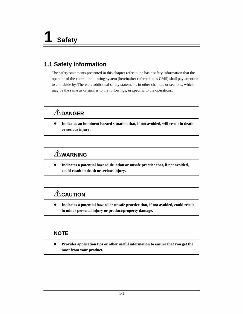
1.1 Safety Information The safety statements presented in this chapter refer to the basic safety information that the operator of the central monitoring system (hereinafter referred to as CMS) shall pay attention to and abide by. There are additional safety statements in other chapters or sections, which may be the same as or similar to the followings, or specific to the operations.
DANGER
Indicates an imminent hazard situation that, if not avoided, will result in death or serious injury.
WARNING
Indicates a potential hazard situation or unsafe practice that, if not avoided, could result in death or serious injury.
CAUTION
Indicates a potential hazard or unsafe practice that, if not avoided, could result in minor personal injury or product/property damage.
NOTE
Provides application tips or other useful information to ensure that you get the most from your product.
1-2
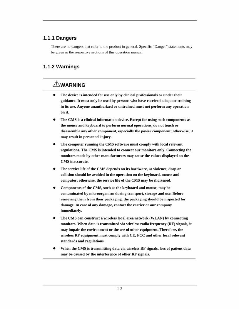
1.1.1 Dangers There are no dangers that refer to the product in general. Specific “Danger” statements may be given in the respective sections of this operation manual
1.1.2 Warnings
WARNING
The device is intended for use only by clinical professionals or under their guidance. It must only be used by persons who have received adequate training in its use. Anyone unauthorized or untrained must not perform any operation on it.
The CMS is a clinical information device. Except for using such components as the mouse and keyboard to perform normal operations, do not touch or disassemble any other component, especially the power component; otherwise, it may result in personnel injury.
The computer running the CMS software must comply with local relevant regulations. The CMS is intended to connect our monitors only. Connecting the monitors made by other manufacturers may cause the values displayed on the CMS inaccurate.
The service life of the CMS depends on its hardware, so violence, drop or collision should be avoided in the operation on the keyboard, mouse and computer; otherwise, the service life of the CMS may be shortened.
Components of the CMS, such as the keyboard and mouse, may be contaminated by microorganism during transport, storage and use. Before removing them from their packaging, the packaging should be inspected for damage. In case of any damage, contact the carrier or our company immediately.
The CMS can construct a wireless local area network (WLAN) by connecting monitors. When data is transmitted via wireless radio frequency (RF) signals, it may impair the environment or the use of other equipment. Therefore, the wireless RF equipment must comply with CE, FCC and other local relevant standards and regulations.
When the CMS is transmitting data via wireless RF signals, loss of patient data may be caused by the interference of other RF signals.
1-3
1.1.3 Cautions
CAUTION
Federal Law (USA) restricts this device to sale by or on the order of a physician.
Hospitals without stable power source should use an Uninterruptible Power Supply (UPS) to power the CMS. When there is a power failure, the system should be shut down by following the specified shutdown procedure before the UPS is turned off. If the system has a sudden power failure, system failure may occur and consequently the system will not work correctly next time or even have a serious result.
Never start or transport the system under the condition other than that specified; otherwise, the system may be damaged. We shall assume no responsibility for such damages.
System time should be set before the CMS is put into use. If the system time is modified when the CMS is running, the data that has been stored may get lost or the network may be interrupted.
Be sure to use standard thermal recorder paper only; otherwise, the recorder may show poor quality on record, or may be unusable, or the print head of the recorder may be damaged.
The CMS is capable of connecting up to 32 monitors and telemetry transmitters. The cable connecting the monitor to the hub or exchange shall not exceed 100m; otherwise, it may result in network overload or weak network signals and consequently errors will occur during data transmission or displaying.
The host of the CMS should be maintained every three to six months. Its long time continuous operating may lead to failure of the operating system.
The host of the CMS should be installed with the original Microsoft Windows’s system and standard upgrade program, such as the service package. Illegal software may lead to abnormal or incorrect system operating.
If Windows® XP® Professional Embedded OS is used, please make sure that it is only used for the CMS software rather than other purposes, such as office use, entertainment. The Microsoft Office that you have installed shall only be used for the CMS software.
Using the “Show Desktop” feature in Windows is prohibited. Installing or using any other software not provided by Minddray DS is prohibited. Softwares that have not been tested or verified by Minddray DS may cause the instability of the system. Minddray DS assumes no responsibility for this.

1-4
CAUTION
If Windows® XP® Professional Embedded operating system is installed, please do not use the system until you have read the end user license agreement (“EULA”). Any use of the system will constitute your agreement to the EULA.
When printing data through an external printer, be sure to follow the printer’s instructions. In case any problem occurs during printing, consult the printer’s instructions.
To ensure the safety and stability of the network, the LAN connecting the CMS and the monitors should be a closed network which is not connected with the internet or other external networks.
1.1.4 Notes
NOTE
Keep this manual close to the CMS so that it can be obtained conveniently when necessary.
Choose a location that affords an unobstructed view of the CMS’s screen and easy access to the operating and maintaining.
If the computer installed with the CMS can not work normally due to its hardware failure or the operating system failure, contact our local service representative.
1-5
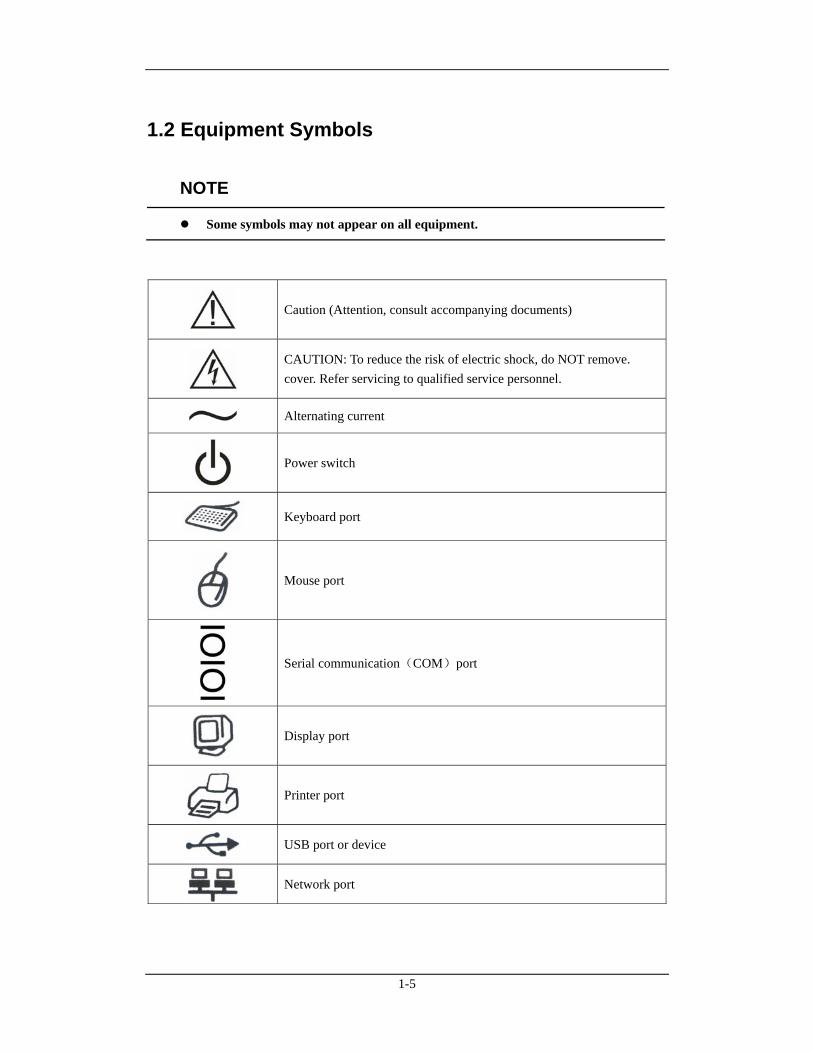
1.2 Equipment Symbols
NOTE
Some symbols may not appear on all equipment.
Caution (Attention, consult accompanying documents)
CAUTION: To reduce the risk of electric shock, do NOT remove. cover. Refer servicing to qualified service personnel.
Alternating current
Power switch
Keyboard port
Mouse port
Serial communication(COM)port
Display port
Printer port
USB port or device
Network port
1-6
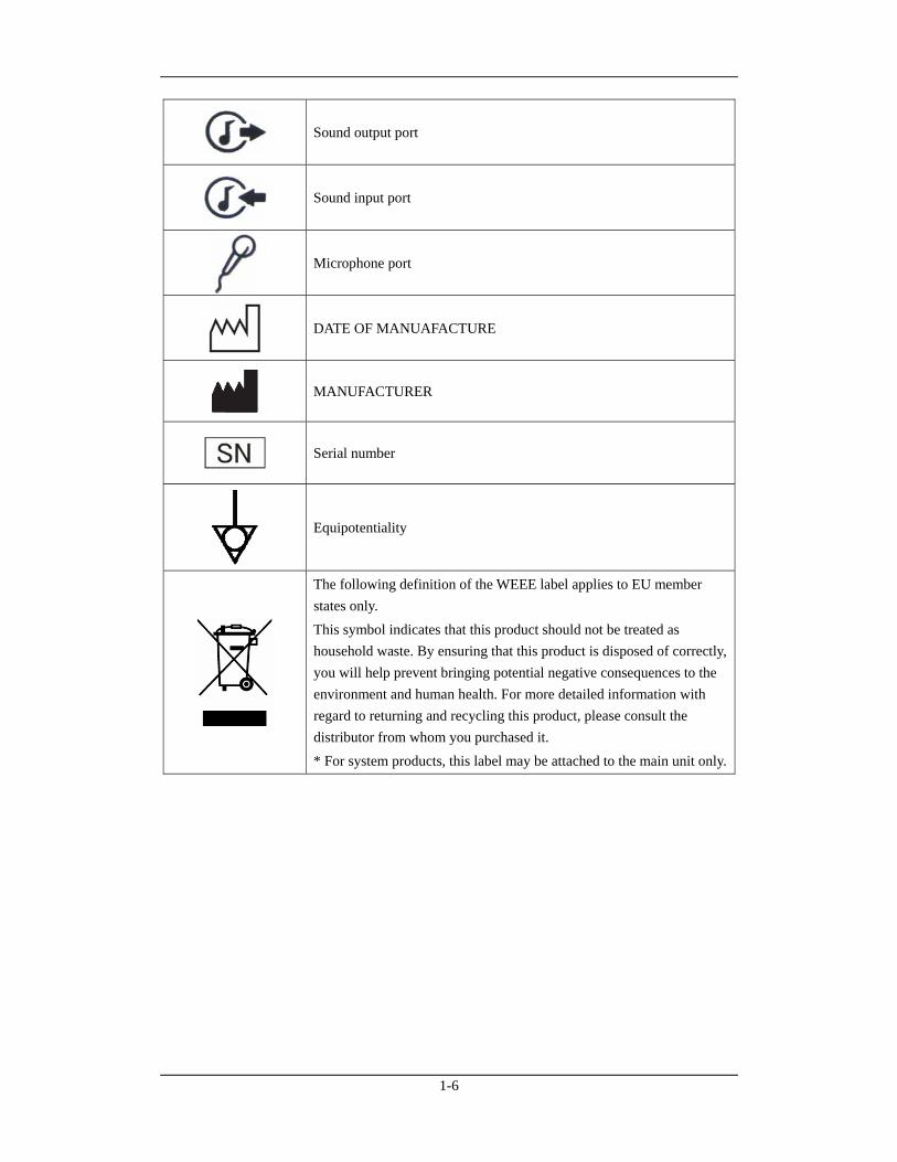
Sound output port
Sound input port
Microphone port
DATE OF MANUAFACTURE
MANUFACTURER
Serial number
Equipotentiality
The following definition of the WEEE label applies to EU member states only. This symbol indicates that this product should not be treated as household waste. By ensuring that this product is disposed of correctly, you will help prevent bringing potential negative consequences to the environment and human health. For more detailed information with regard to returning and recycling this product, please consult the distributor from whom you purchased it. * For system products, this label may be attached to the main unit only.
2-1
2 The Basics
2.1 Intended Use The CMS network transfers information between DPM Central Station and other networked devices. It also allows information transfer between several CMS. Network connections consist of hardwired network cables and/or WLAN connections. CMS can be used for remote monitor management, storing, printing, reviewing or processing of information from networked devices, and it is operated by medical personnel in hospitals or medical institutions.
WARNING
The device is intended for use only by clinical professionals or under their guidance. It must only be used by persons who have received adequate training in its use. Anyone unauthorized or untrained must not perform any operation on it.
2.2 Application Scope of the Manual For the central monitoring system connecting monitors which use “CMS network protocol” or connecting defibrillator, the following sections of this manual may not be applicable. 5.1.1 Admitting Patient through CMS 5.1.2 Admitting Patient through the Monitor 5.4 Modifying Patient Information 7.3 Parameter Setup 7.4.1 Alarm Setup 7.4.2 Silencing Alarms on Monitors 7.4.3 Pausing Alarm Sound on Monitors 7.4.4 Silencing a Bedside Monitor 7.4.5 Pausing Alarms on Monitors 7.4.6 STANDBY 7.4.7 Controlling a Bedside Monitor to Exit STANDBY 7.4.8 NIBP Measurement 8.4 Alarm Setup 8.5 Pausing Alarms 8.6 Silencing Alarms 8.7 Pausing Alarm Sound on Monitors 8.8 Silencing the Monitors 8.9 Latching Alarms
2-2
2.3 Contraindications None.
2.4 Functions The CMS comprises powerful system software and high-performance computer components. It constructs a monitoring network by connecting monitors and telemetry transmitters. By collecting, processing, analyzing and outputting the information coming from monitors and telemetry transmitters, the CMS can achieve centralized monitoring over multiple patients so as to greatly promote the efficiency and quality of the monitoring work. The CMS:
Is capable of connecting up to 32 monitors that supports the CMS or CMS+ network protocol.
Is capable of connecting up to 32 telemetry transmitters.
Supports any bed’s (1-32 bed) frequency setup by each telemetry monitoring system.
Supports multi-screen display mode, including up to four local displays and multiple remote displays; supports remote large screen display.
Is capable of displaying information from 16 monitors in the single-screen mode and 32 monitors in the dual- or multi-screen mode.
Allows you to view a single patient emphatically.
Supports the networking between multiple CMSs and the “Remote CMS”.
Allows you to review up to 240 hours of trend data for each online patient.
Allows you to review up to 720 events for each online patient.
Allows you to review up to 100 OxyCRG events for each online patient.
Allows you to review a 4-hour dynamic short trend for each online patient.
Allows you to review up to 240 hours of ST segments for each online patient.
Allows you to review up to 240 hours of waveforms for each online patient.
Allows you to review up to 240 hours of compressed waveforms for each online patient.
Allows you to review up to 240 hours of NIBP measurements for each online patient.
Is capable of storing discharged patients’ full disclosure waveforms, parameters, alarms and so on ; allows you to search and review the data of up to 20,000 discharged patients.
Provides the patient information management function.
Provides audible and visual alarms.
Provides the functions of drug calculations, titration table calculations, hemodynamics calculations, oxygenation calculations, ventilation calculations and renal calculations.

2-3
Provides the functions to record, print and save data.
Provides comprehensive help information, prompts and operational guide.
Provides 1280×1024 high display resolution.
Provides two waveform display modes: color and mono.
Facilitates the setup of language, waveform and parameter color.
Supports such peripherals as the keyboard, mouse, thermal recorder, laser printer, speaker, etc.
Supports wired and wireless network..
Provides data output meeting the HL7 protocol. Refer to eGateway HL7 Reference Manual for details. To obtain this protocol, contact local Mindray DS service representative or Mindray DS Customer Service Department.
Supports receiving the data generated during interruption from networked monitors and combining the data.
Supports CMS’ running on the virtual machine.
Supports the redundancy backup by two hard disks on the host computer.
The CMS has a USB dongle to protect the copyright. You must plug the dongle into the system’s USB interface before starting the system. Otherwise, the system cannot start. Also the USB dongle is used to configure the optional system functions.
NOTE
If the CMS has only one USB connector, it is intended for connecting the USB dongle only. Otherwise, the system cannot start up. If the CMS has more than one USB connector, there must be one dedicated for the USB dongle and the others can be used for other purposes.
The USB dongle is used to configure the optional system functions which may be different for different CMSs, So don’t exchange the USB dongles.
If you lost your dongle, please contact us to get a new one.
2-4
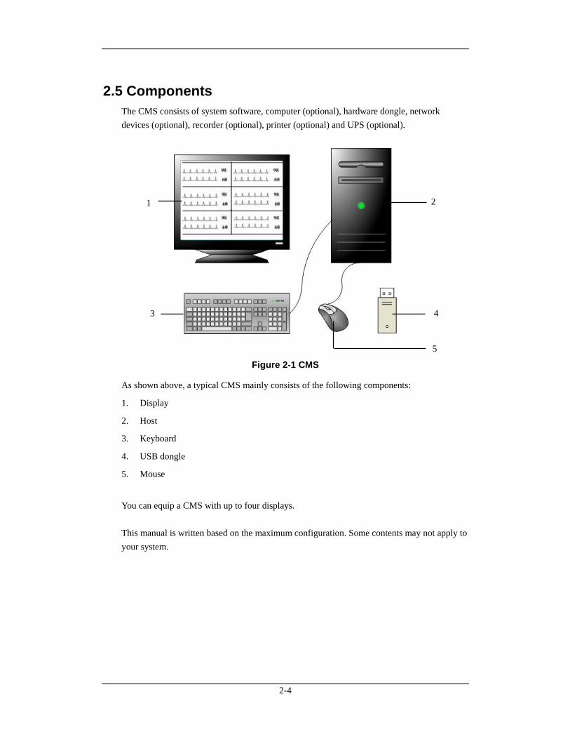
2.5 Components The CMS consists of system software, computer (optional), hardware dongle, network devices (optional), recorder (optional), printer (optional) and UPS (optional).
Figure 2-1 CMS
As shown above, a typical CMS mainly consists of the following components:
1. Display
2. Host
3. Keyboard
4. USB dongle
5. Mouse
You can equip a CMS with up to four displays. This manual is written based on the maximum configuration. Some contents may not apply to your system.
1 2
3 4
5
2-5
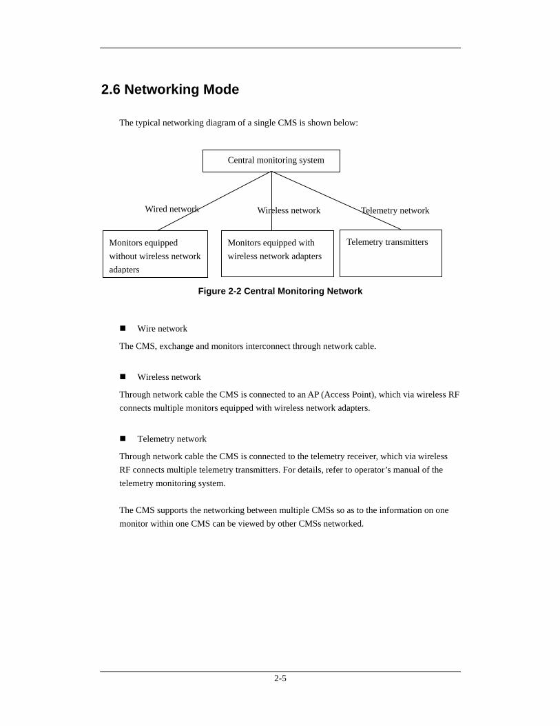
2.6 Networking Mode The typical networking diagram of a single CMS is shown below:
Figure 2-2 Central Monitoring Network
Wire network
The CMS, exchange and monitors interconnect through network cable.
Wireless network
Through network cable the CMS is connected to an AP (Access Point), which via wireless RF connects multiple monitors equipped with wireless network adapters.
Telemetry network
Through network cable the CMS is connected to the telemetry receiver, which via wireless RF connects multiple telemetry transmitters. For details, refer to operator’s manual of the telemetry monitoring system. The CMS supports the networking between multiple CMSs so as to the information on one monitor within one CMS can be viewed by other CMSs networked.
Wireless networkWired network Telemetry network
Central monitoring system
Monitors equipped without wireless network adapters
Monitors equipped with wireless network adapters
Telemetry transmitters
2-6
2.7 Controls
2.7.1 Mouse
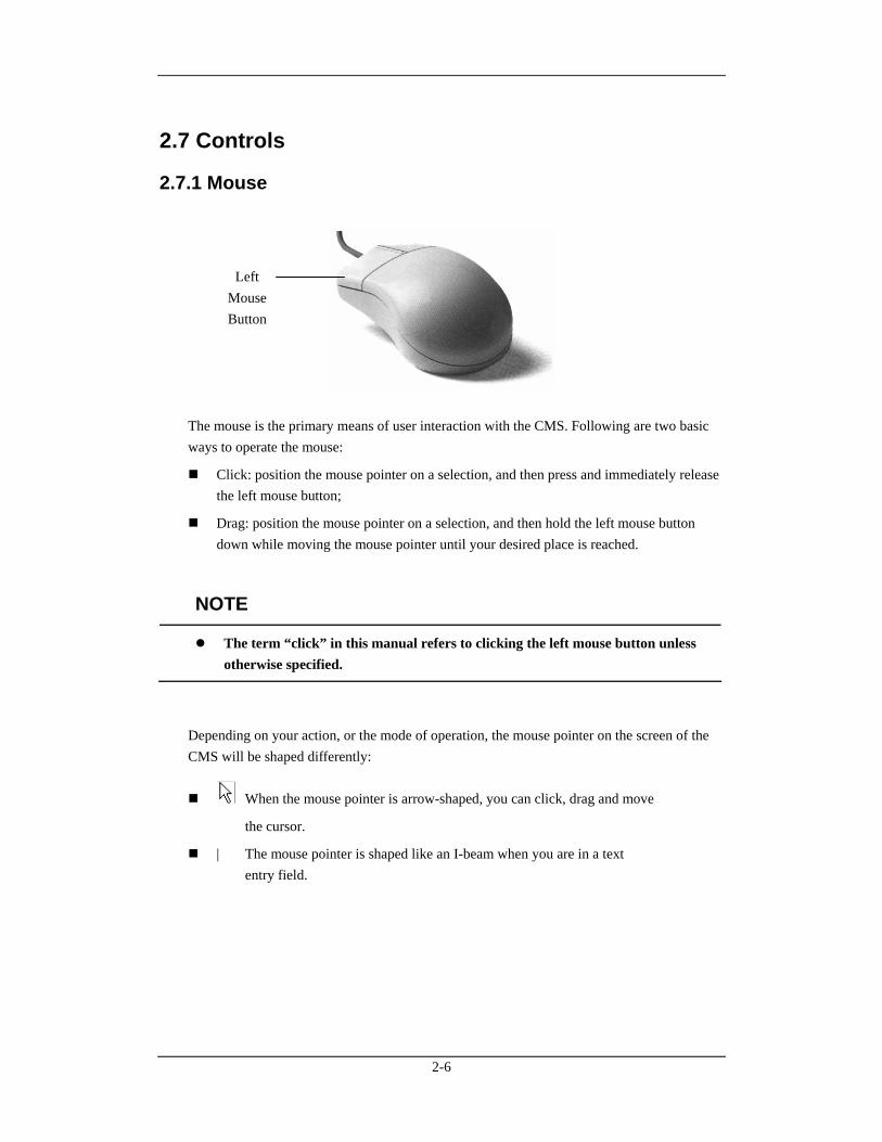
The mouse is the primary means of user interaction with the CMS. Following are two basic ways to operate the mouse:
Click: position the mouse pointer on a selection, and then press and immediately release the left mouse button;
Drag: position the mouse pointer on a selection, and then hold the left mouse button down while moving the mouse pointer until your desired place is reached.
NOTE
The term “click” in this manual refers to clicking the left mouse button unless otherwise specified.
Depending on your action, or the mode of operation, the mouse pointer on the screen of the CMS will be shaped differently:
When the mouse pointer is arrow-shaped, you can click, drag and move
the cursor.
| The mouse pointer is shaped like an I-beam when you are in a text entry field.
Left Mouse Button
2-7
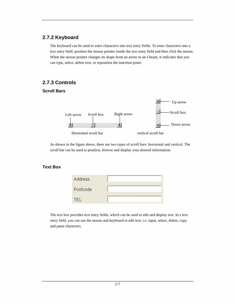
2.7.2 Keyboard The keyboard can be used to enter characters into text entry fields. To enter characters into a text entry field, position the mouse pointer inside the text entry field and then click the mouse. When the mouse pointer changes its shape from an arrow to an I-beam, it indicates that you can type, select, delete text, or reposition the insertion point.
2.7.3 Controls Scroll Bars
Horizontal scroll bar vertical scroll bar As shown in the figure above, there are two types of scroll bars: horizontal and vertical. The scroll bar can be used to position, browse and display your desired information.
Text Box
The text box provides text entry fields, which can be used to edit and display text. In a text entry field, you can use the mouse and keyboard to edit text, i.e. input, select, delete, copy and paste characters.
Left arrow Right arrowScroll box
Up arrow
Down arrow
Scroll box
2-8
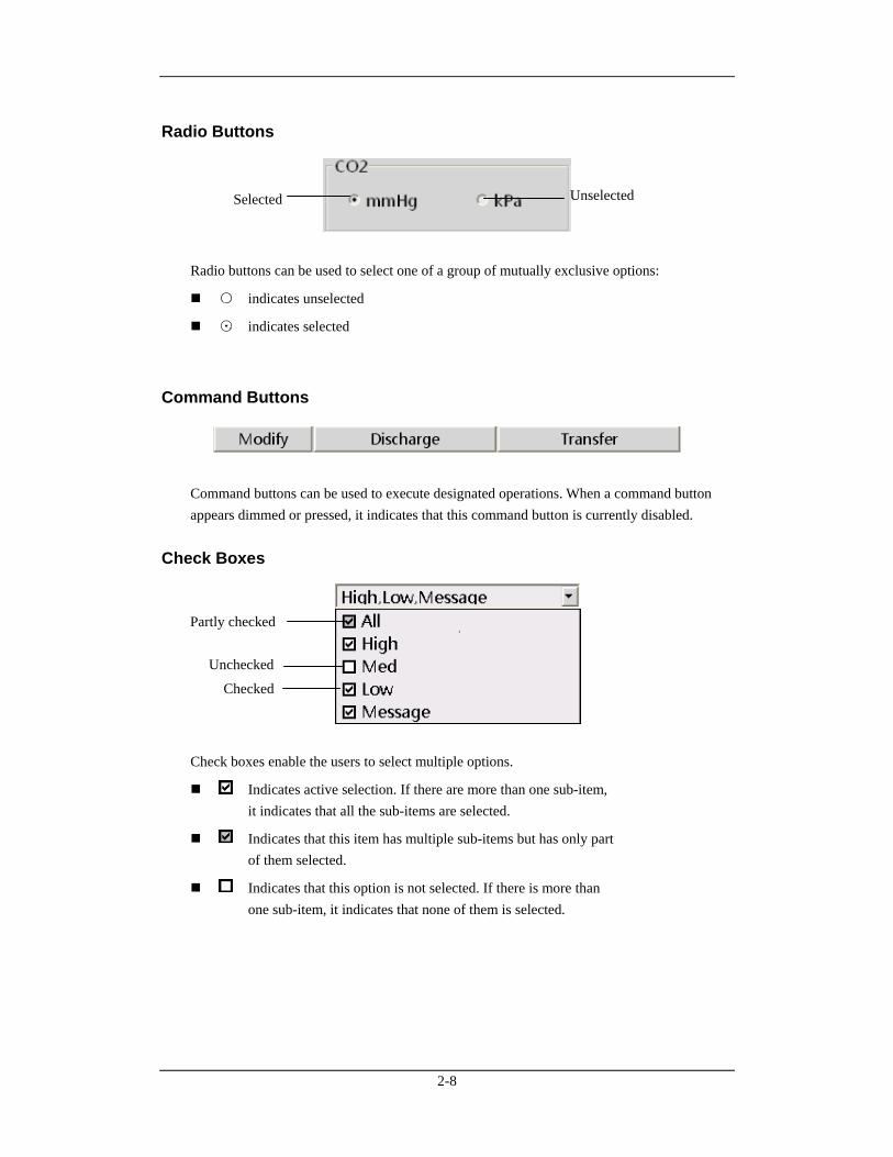
Radio Buttons
Radio buttons can be used to select one of a group of mutually exclusive options:
○ indicates unselected
⊙ indicates selected
Command Buttons
Command buttons can be used to execute designated operations. When a command button appears dimmed or pressed, it indicates that this command button is currently disabled.
Check Boxes
Check boxes enable the users to select multiple options.
Indicates active selection. If there are more than one sub-item, it indicates that all the sub-items are selected.
Indicates that this item has multiple sub-items but has only part of them selected.
Indicates that this option is not selected. If there is more than one sub-item, it indicates that none of them is selected.
Selected Unselected
Partly checked
Unchecked
Checked
2-9
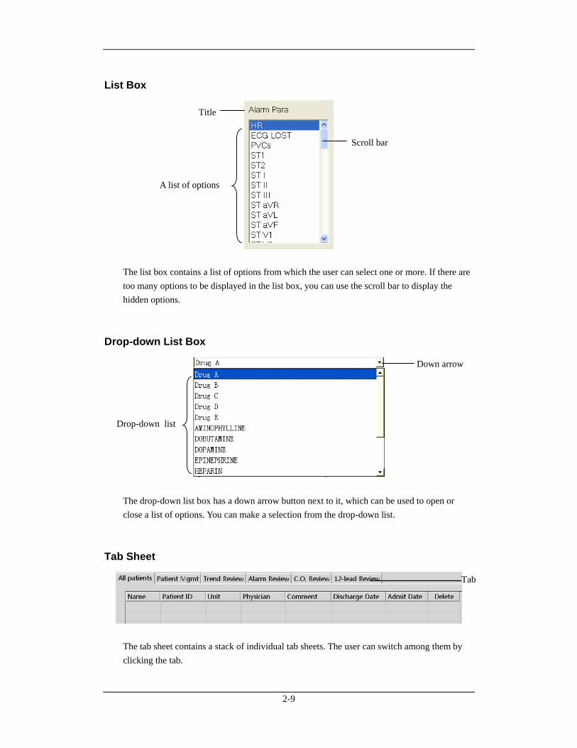
List Box
The list box contains a list of options from which the user can select one or more. If there are too many options to be displayed in the list box, you can use the scroll bar to display the hidden options.
Drop-down List Box
The drop-down list box has a down arrow button next to it, which can be used to open or close a list of options. You can make a selection from the drop-down list.
Tab Sheet
The tab sheet contains a stack of individual tab sheets. The user can switch among them by clicking the tab.
Down arrow
Drop-down list
Scroll bar
A list of options
Title
Tab

2-10
FOR YOUR NOTES
3-1
3 Installation and Maintenance
3.1 Unpacking and Inspection Be careful to remove the host, displays and other components from their packaging and check if every item on the Packing List has been received without mechanical damage. If you have any question, contact our company immediately.
NOTE
Please save the packaging materials for later transport or storage use.
WARNING
Be sure to keep the packaging materials from children’s reach.
Disposal of the packaging materials shall comply with your local requirements.
Components of the CMS, such as the keyboard and mouse, may be contaminated by microorganism during transport, storage and use. Before removing them from their packaging, the packaging should be inspected for damage. In case of any damage, contact the carrier or our company immediately.
3-2
3.2 Installation
WARNING
The CMS should be installed by manufacturer designated personnel. The copyright of the CMS software is solely owned by our company. No organization or individual shall resort to juggling, copying, or exchanging it or to any other infringement on it in any form or by any means without due permission.
NOTE
Never place the CMS within a patient environment.
Place the CMS in an environment that the system can be easily viewed, operated and maintained.
3.2.1 Environmental Requirements Each component of the CMS must work under the specified environment. The environment where the CMS is installed should be reasonably free from noises, vibration, dust, corrosive, flammable and explosive substances. If the CMS is installed in a cabinet, sufficient space in front and behind should be left for convenient operation, maintenance and repair. Moreover, to maintain good ventilation, the CMS should be at least 2 inches (5cm) away from around the cabinet. When the CMS is moved from one place to another, condensation may occur as a result of temperature or humidity difference. In this case, never start the system before the condensation disappears.
3-3
3.2.2 Power Requirements Each component of the CMS must be powered by the specified power source. To protect the hospital personnel from electric shock, the CMS (including the host and displays) and its recorder must have their casings properly grounded. The host of the CMS is provided with a 3-wire power cable, which must be plugged into a properly grounded 3-wire receptacle. If a 3-wire, grounded receptacle is not available, consult the hospital electrician.
WARNING
Make sure that the operating environment and power source of the CMS meet the specific requirements; otherwise, unexpected consequences, e.g. damage to the equipment, may result.
Appropriate power supply must be selected according to the setup of the system power voltage; otherwise, serious damage may be caused to the system.
Never use a 3-wire to 2-wire adapter with any unit of the CMS.
3.2.3 Installation Manufacturer designated personnel will install the CMS for you. If you want to move your system to another place, contact our company.
WARNING
We shall assume no responsibility for any loss caused by installing or moving the CMS without our permission.
3.2.3.1 Installation for Remote Display
The CMS supports the display of local video on remote display through VGA video extension device.
Transmitter
1. Receive the VGA signal of the CMS into the VGA interface of INPUTS of transmitter.
2. Connect the local display of the CMS with the VGA interface of OUTPUTS of transmitter.
3. Connect one end of network cable with the RJ45 OUT interface of transmitter.
4. Connect the power adapter with the POWER interface of transmitter.
3-4
Receiver
1. Connect the input port of remote equipment (such as a display or a LCD TV) with the VGA interface of OUTPUT1 or OUTPUT2 of receiver.
2. Connect one end of network cable with the RJ45 IN interface of receiver.
3. Connect the power adapter with the POWER interface of receiver.
4. The brightness and contrast on the remote display equipment can be finely adjusted through “Brightness” and “Contrast” buttons on receiver.
NOTE
The CMS supports VGA video extension. For specific equipment recommendations, contact your Mindray sales representative.
If multiplex video signals are required to be displayed in separate screens, use other types of transmission equipment.
The remote display equipment is required to support a resolution of 1280×1024 pixels.
Please refer to the accompanying documents for the detailed operations, installation, specifications and precautions of VGA video transmission equipment.
3.2.3.2 Installation for Remote USB Control
The CMS can achieve the control for remote USB through USB twisted pair cable transmission device.
1. Firmly connect the USB-B port of remote USB control device with USB port of the CMS through USB 2.0 wire.
2. Connect the transmission device (such as keyboard/mouse) with the user-end equipment of remote USB control device.
3. Connect the host with user-end equipment by network cable.
4. Check if the LED lamp (green) of RJ45 interface is lit. If the lamp is lit, it indicates that the equipment is already powered on for normal use.
NOTE
The CMS supports the remote transmission of USB control. For specific equipment recommendations, contact your Mindray sales representative.
When the user-end USB device is installed, it needs 1 to 2 minutes to implement USB self-test. Please wait for a while.
Please refer to the accompanying documents for the detailed operations, installation, specifications and precautions of USB transmission equipment.
3-5
3.3 Starting the System Follow this procedure to start your system:
1. Perform safety checks before starting your system. For details, refer to 3.5.1 General Inspection.
2. Connect the USB dongle to the USB interface of the host. (If the dongle has been connected, skip this step.)
3. Turn on the UPS and power on the system.
4. Press the power switches on the host and displays to start the operating system.
5. The system will perform a series of self-tests with corresponding information displayed on the screen.
6. If the self-tests pass, the system will beep three times and enter the main screen immediately.
If there is a self-test failure, the system will beep and give an error message.
CAUTION
To prevent unexpected errors or consequences from a sudden power failure, it is recommended that your CMS is equipped with an UPS.
NOTE
If the computer beeps during self-tests or startup, consult the manual provided with the computer.
3-6
3.4 Shutting down the System It is important to shut down the system properly. Follow this simple procedure to properly shut down your system. This prevents inadvertent errors from occurring during system shut down.
1. Click “System Setup” button.
2. Select “Shutdown” from “General Setup”.
3. The system will check if any patient is being monitored.
If no patients are being monitored, directly enter the next step.
If there are still some patients being monitored, the message box “× patients are being monitored. Are you sure you want to shut down?” will be displayed. You can either select “Yes” to enter the next step, or select “No” to close the message box and not continue the shutdown process.
4. A message box asking whether to shut down the system will be displayed. Select “Yes” from the message box.
If no shutdown password is required, the CMS will quit with the operating system shut down and the host powered off.
If a shutdown password is required, a dialog box will pop up. You should enter the required password and select “OK”. The CMS will quit with the operating system shut down and the host powered off
5. If an UPS is used, turn it off.
6. Disconnect the power cord of each device from the power outlet.
CAUTION
Hospitals without a stable power source should use a UPS to provide power to the CMS. The UPS must not be turned off. When there is a power failure, the system should be shut down by following the specified shutdown procedure before the UPS is exhausted. When the system has a sudden power failure, system failure may occur and consequently the system will not work correctly next time or even have a serious result.
3-7
3.5 Maintenance
WARNING
Failure on the part of the responsible hospital or institution employing the use of the CMS to implement a satisfactory maintenance schedule may cause undue equipment failure and possible health hazard.
The safety checks or servicing involving any disassembly or decomposition of devices should be performed by professional servicing personnel; otherwise, it may lead to undue equipment failure and possible health hazards.
Turn off the CMS if no patients are to be monitored. If the system has been running for half a year continuously, restart the system.
In the period of the CMS restarting, patients’ data will not be stored. To prevent any loss, please restart your system without any patient under monitoring.
3.5.1 General Inspection Whenever your system is repaired, upgraded or has been used for 6-12 months, a thorough inspection should be performed by qualified service personnel to ensure the reliability. Before the CMS is put into use and when it is in use, follow these guidelines to inspect it:
Inspect the equipment and its accessories for mechanical damage.
Inspect if the environment and power supply meet the specific requirements.
Inspect all power cords and signal lines for fraying or other damages, and if they are properly connected and insulated.
Inspect if the sound system functions normally.
Inspect if each function of the system is in good condition.
In case of any damage or abnormity, do not use the CMS. Contact the hospital biomedical engineers or our service personnel immediately.
3-8
3.5.2 General Cleaning
WARNING
Be sure to shut down the system and disconnect all power cords from the outlet before cleaning the equipment.
Your equipment should be cleaned on a regular basis. If there is heavy pollution in your place or your place is very dusty and sandy, the equipment should be cleaned more frequently. The equipment to be cleaned includes the host, displays, printer, recorder, keyboard and mouse. Before cleaning the equipment, consult your hospital’s regulations for cleaning, disinfecting and sterilizing equipment
Cleaning Agents
The exterior surfaces of the equipment may be cleaned with a clean and soft cloth, sponge or cotton ball, dampened with a non-erosive cleaning solution. Drying off excess cleaning solution before cleaning the equipment is recommended. Following are examples of cleaning solutions:
Hydrogen peroxide (3%)
Ethyl alcohol (70%)
Workstation/server cleaning solutions
Liquid crystal display (LCD) detergent
3-9
To avoid damage to the equipment, follow these rules:
CAUTION
Failure to follow these rules may melt, distort, or dull the finish of the case, blur lettering on the labels, or cause equipment failures.
ALWAYS dilute the solutions according to the manufacturer’s suggestions.
ALWAYS wipe off all the cleaning solution with a dry cloth after cleaning.
NEVER SUBMERGE the equipment into water or any cleaning solution, or POUR or SPRAY water or any cleaning solution on the equipment.
NEVER permit fluids run into the casing, switches, connectors, or any ventilation openings in the equipment.
NEVER use abrasive materials and erosive or acetone –based cleaners.
WARNING
Disinfection or sterilization may cause damage to the equipment; therefore, when preparing to disinfect or sterilize the equipment, consult your hospital’s infection controllers or professionals.
The cleaning solutions above can only be used for general cleaning. If you use them to control infections, we shall assume no responsibility for the effectiveness.

3-10
FOR YOUR NOTES
4-1
4 Display
4.1 Overview The central monitoring system can support single-, dual- and multi- screen display modes. The main screen and auxiliary screen vary in different display modes.
4.2 Single-Screen Mode
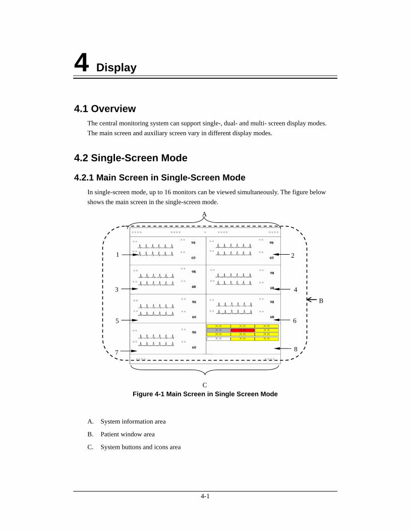
4.2.1 Main Screen in Single-Screen Mode In single-screen mode, up to 16 monitors can be viewed simultaneously. The figure below shows the main screen in the single-screen mode.
Figure 4-1 Main Screen in Single Screen Mode
A. System information area
B. Patient window area
C. System buttons and icons area
A
C
1
3
5
7
2
4
6
8
B
4-2
NOTE
In single-screen mode, maximum 16 monitors can be viewed simultaneously. If monitors connected to a CMS are more than 16 but less than 32, we recommend you to use dual- or multi- screen mode.
System Information Area
In this area, the following information is displayed:
1 Hospital information: Displays the hospital and office where the CMS is located.
2
System alarm icon area: Display icon if in system silence or icon if in
system alarm audio off.
3 System alarm area: Displays the prompts or alarms coming from the system itself. If more than one message occurs, they will be displayed circularly. Please refer to the Appendix B for all the system alarms.
4 Current time: Displays the current time.
Patient Window Area
For details, refer to 6.2 Patient Window.
System Buttons and Icons Area
System buttons include:
1 Silence: Click to silence the CMS. For details. Refer to 8.10 CMS System Silence.
2 Admit Patient: Click it to enter the “Connected patient list” screen.
3 System Setup: Click it to enter the “System Setup” window.
4 Discharged Pat.: Click it to enter the “Discharged Patients” window.
5 Remote CMS: Click it enter the “Remote CMS” window.
6 Main Screen/ViewBed:
Click it to close the auxiliary screen and return to the main screen/ Click it to enter the “ViewBed” tab sheet.
4-3
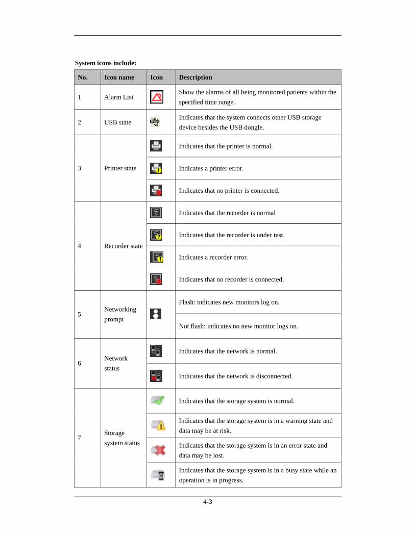
System icons include:
No. Icon name Icon Description
1 Alarm List Show the alarms of all being monitored patients within the specified time range.
2 USB state Indicates that the system connects other USB storage device besides the USB dongle.
Indicates that the printer is normal.
Indicates a printer error. 3 Printer state
Indicates that no printer is connected.
Indicates that the recorder is normal
Indicates that the recorder is under test.
Indicates a recorder error.
4 Recorder state
Indicates that no recorder is connected.
Flash: indicates new monitors log on.
5 Networking prompt
Not flash: indicates no new monitor logs on.
Indicates that the network is normal.
6 Network status
Indicates that the network is disconnected.
Indicates that the storage system is normal.
Indicates that the storage system is in a warning state and data may be at risk.
Indicates that the storage system is in an error state and data may be lost.
7 Storage system status
Indicates that the storage system is in a busy state while an operation is in progress.
4-4
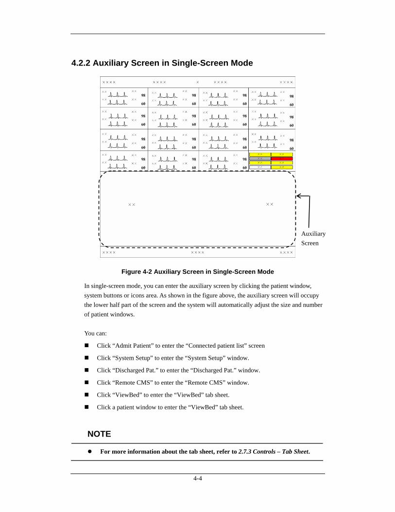
4.2.2 Auxiliary Screen in Single-Screen Mode
Figure 4-2 Auxiliary Screen in Single-Screen Mode
In single-screen mode, you can enter the auxiliary screen by clicking the patient window, system buttons or icons area. As shown in the figure above, the auxiliary screen will occupy the lower half part of the screen and the system will automatically adjust the size and number of patient windows. You can:
Click “Admit Patient” to enter the “Connected patient list” screen
Click “System Setup” to enter the “System Setup” window.
Click “Discharged Pat.” to enter the “Discharged Pat.” window.
Click “Remote CMS” to enter the “Remote CMS” window.
Click “ViewBed” to enter the “ViewBed” tab sheet.
Click a patient window to enter the “ViewBed” tab sheet.
NOTE
For more information about the tab sheet, refer to 2.7.3 Controls – Tab Sheet.
Auxiliary Screen
4-5
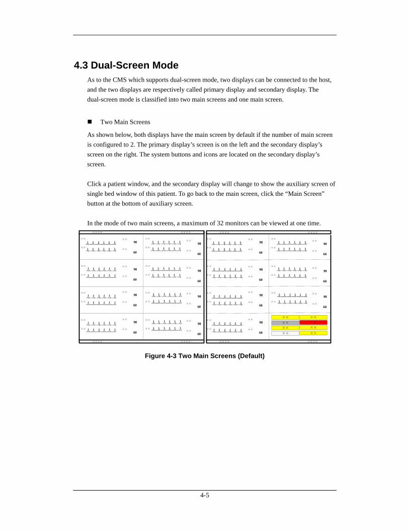
4.3 Dual-Screen Mode As to the CMS which supports dual-screen mode, two displays can be connected to the host, and the two displays are respectively called primary display and secondary display. The dual-screen mode is classified into two main screens and one main screen.
Two Main Screens
As shown below, both displays have the main screen by default if the number of main screen is configured to 2. The primary display’s screen is on the left and the secondary display’s screen on the right. The system buttons and icons are located on the secondary display’s screen. Click a patient window, and the secondary display will change to show the auxiliary screen of single bed window of this patient. To go back to the main screen, click the “Main Screen” button at the bottom of auxiliary screen. In the mode of two main screens, a maximum of 32 monitors can be viewed at one time.
××
××
××
××
××
××
××
××
××
××
××
××
××
××
××
××
×× 98
××
60
×× 98
××
60
×× 98
××
60
×× 98
××
60
×× 98
××
60
×× 98
××
60
×× 98
××
60
×× 98
××
60
××
××
××
××
××
××
××
××
××
××
××
××
××
××
×× 98
××
60
×× 98
××
60
×× 98
××
60
×× 98
××
60
×× 98
××
60
×× 98
××
60
×× 98
××
60
×× ××
××
××
××
××
××
××
×××× ×××××××× ××××
×××× ×××××××× ××××
Figure 4-3 Two Main Screens (Default)
4-6
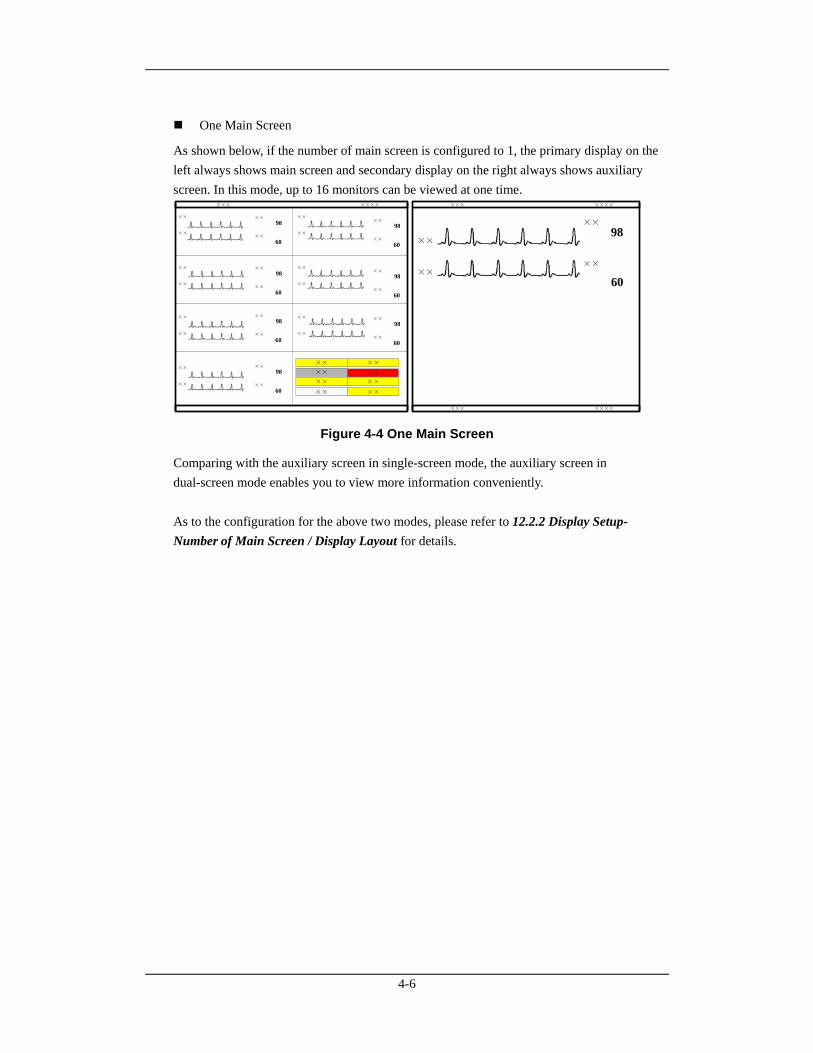
One Main Screen
As shown below, if the number of main screen is configured to 1, the primary display on the left always shows main screen and secondary display on the right always shows auxiliary screen. In this mode, up to 16 monitors can be viewed at one time.
××
××
××
××
××
××
××
××
××
××
××
××
××
××
×× 98
××
60
×× 98
××
60
×× 98
××
60
×× 98
××
60
×× 98
××
60
×× 98
××
60
×× 98
××
60
××
98
××
60
××
××
××× ××××
×× ××
××
×× ××
×× ××
××
××× ××××××× ××××
Figure 4-4 One Main Screen
Comparing with the auxiliary screen in single-screen mode, the auxiliary screen in dual-screen mode enables you to view more information conveniently. As to the configuration for the above two modes, please refer to 12.2.2 Display Setup- Number of Main Screen / Display Layout for details.
4-7
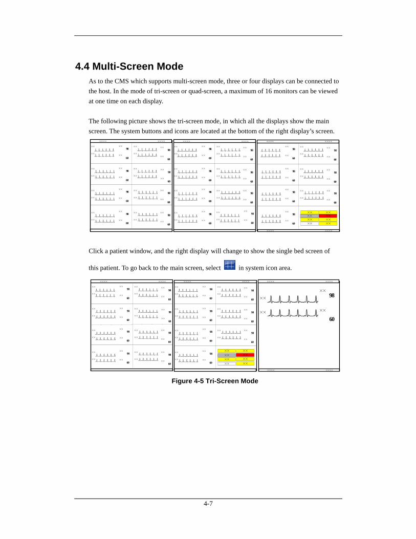
4.4 Multi-Screen Mode As to the CMS which supports multi-screen mode, three or four displays can be connected to the host. In the mode of tri-screen or quad-screen, a maximum of 16 monitors can be viewed at one time on each display. The following picture shows the tri-screen mode, in which all the displays show the main screen. The system buttons and icons are located at the bottom of the right display’s screen.
××
××
××
××
××
××
××
××
××
××
××
××
××
××
××
××
×× 98
××
60
×× 98
××
60
×× 98
××
60
×× 98
××
60
×× 98
××
60
×× 98
××
60
×× 98
××
60
×× 98
××
60
××
××
××
××
××
××
××
××
××
××
××
××
××
××
×× 98
××
60
×× 98
××
60
×× 98
××
60
×× 98
××
60
×× 98
××
60
×× 98
××
60
×× 98
××
60
×××× ×××××××× ××××
××
××
××
××
××
××
×× 98
××
60
×× 98
××
60
×× 98
××
60
×× 98
××
60
×× 98
××
60
×× 98
××
60
×× 98
××
60
××××
××
×××× ××××
××××
××
×× 98
××
60××
××
××
××
×××× ×××× Click a patient window, and the right display will change to show the single bed screen of
this patient. To go back to the main screen, select in system icon area.
××
××
××
××
××
××
××
××
××
××
××
××
××
××
××
××
×× 98
××
60
×× 98
××
60
×× 98
××
60
×× 98
××
60
×× 98
××
60
×× 98
××
60
×× 98
××
60
×× 98
××
60
×××× ××××
××
××
××
××
××
××
××
××
××
××
××
××
××
××
×× 98
××
60
×× 98
××
60
×× 98
××
60
×× 98
××
60
×× 98
××
60
×× 98
××
60
×× 98
××
60
××
98
××
60
××
××
×× ××
××
××
××
××
××
××
×××× ×××××××× ×××××××× ××××
Figure 4-5 Tri-Screen Mode
4-8
4.5 Screen Layout The setting for multibed screen layout directly decides each patient window’s size, and the total number and layout of patient windows. Please refer to 12.2.2 Display Setup for details.
WARNING
If the monitors connected to the CMS are more than the patient windows that can be displayed on the screen, some monitors will be displayed in the non-spot patient window in which only alarm status can be displayed. To view the waveforms and parameters of a non-spot patient, you can switch it to spot patient window.
5-1
5 Patient Management The CMS enables you to manage patients by:
Admitting patient
Obtaining patient information
Patient information synchronization
Modifying patient information
Discharging patient
Switching patient window
Changing to idle sector
Transferring patient
5.1 Admitting Patient A patient can be monitored only after it is admitted by the CMS. Then the CMS can display the physiological parameters, waveforms and alarm messages and store the data related to this patient. You can admit a patient either at a monitor or at the CMS. After a patient is admitted, the patient window is bound with a monitor and patient data from this monitor will be displayed in the same patient window if it admits a patient next time. For details on patient window, refer to 6.2 Patient Window. If the admitted patient’s number has reached the upper limit, the corresponding message will be displayed. At this time, the CMS cannot admit one more patient. If you really want to admit a patient, perform the “Discharge Patient” operation first. For details, refer to 5.5 Discharging a Patient.
NOTE
A patient can be monitored on the CMS only after the patient monitor is first admitted by the CMS and then the patient is admitted. Refer to 12.2.5 Monitor List on how the monitor is admitted by the CMS.
A defibrillator is not bound with a patient window. Patient information from this defibrillator will be displayed in an idle patient window selected by the CMS according to the sequence of top to bottom and left to right when it admits a patient next time.
5-2
5.1.1 Admitting Patient through CMS When a monitor which has not admitted a patient is connected to the network, you can admit a patient either by:
Clicking a patient window with no patient or an idle sector and selecting “Admit Patient” in the pop-up menu. This is applied to admit patient to a spot patient window. For detail, refer to 6.2 Patient Window, or
Clicking in the icon area or the “Admit Patient” button in the button area and
admitting the patient in the open window.
When icon or the “Admit Patient” button is selected, a window is open, in which
“Connected Patient List” is displayed at the left side and “Patient Info” at the right side. The “Connected Patient List” includes the information of all the monitors using “CMS+ network protocol” and telemetry transmitters connected to the LAN. The information includes monitoring status, monitor name, unit, bed number, patient name, patient ID and details through which you can know more about monitoring status.
NOTE
If a patient is admitted by CMS with the idle bedside monitor in the state of standby, the bedside monitor will automatically exit the standby mode.
5-3
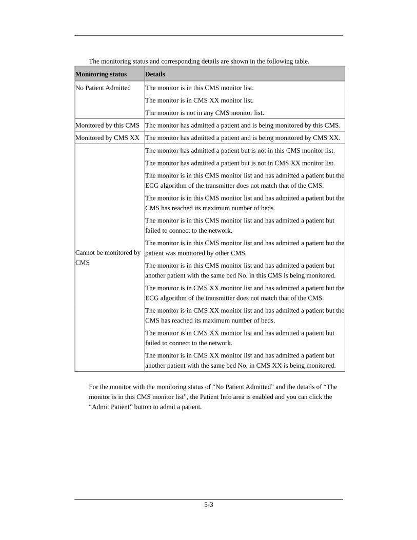
The monitoring status and corresponding details are shown in the following table.
Monitoring status Details
The monitor is in this CMS monitor list.
The monitor is in CMS XX monitor list.
No Patient Admitted
The monitor is not in any CMS monitor list.
Monitored by this CMS The monitor has admitted a patient and is being monitored by this CMS.
Monitored by CMS XX The monitor has admitted a patient and is being monitored by CMS XX.
The monitor has admitted a patient but is not in this CMS monitor list.
The monitor has admitted a patient but is not in CMS XX monitor list.
The monitor is in this CMS monitor list and has admitted a patient but the ECG algorithm of the transmitter does not match that of the CMS.
The monitor is in this CMS monitor list and has admitted a patient but the CMS has reached its maximum number of beds.
The monitor is in this CMS monitor list and has admitted a patient but failed to connect to the network.
The monitor is in this CMS monitor list and has admitted a patient but the patient was monitored by other CMS.
The monitor is in this CMS monitor list and has admitted a patient but another patient with the same bed No. in this CMS is being monitored.
The monitor is in CMS XX monitor list and has admitted a patient but the ECG algorithm of the transmitter does not match that of the CMS.
The monitor is in CMS XX monitor list and has admitted a patient but the CMS has reached its maximum number of beds.
The monitor is in CMS XX monitor list and has admitted a patient but failed to connect to the network.
Cannot be monitored by CMS
The monitor is in CMS XX monitor list and has admitted a patient but another patient with the same bed No. in CMS XX is being monitored.
For the monitor with the monitoring status of “No Patient Admitted” and the details of “The monitor is in this CMS monitor list”, the Patient Info area is enabled and you can click the “Admit Patient” button to admit a patient.
5-4
NOTE
If you directly click on the Admit Patient button before inputting patient information, the patient information will be blank. In this case, you can modify the patient information by referring to 5.4 Modifying Patient Information.
When there is no monitor online, an alarm message “No New Bed Online” will be shown.
When a patient is admitted, his bed number can not be identical to that of any other bed under monitoring. Otherwise, the patient can not be admitted.
In the LAN, a monitor can be admitted by any but only one of the CMSs.
5.1.2 Admitting Patient through the Monitor When a patient is admitted by a monitor, it will be admitted by the CMS synchronously.
5.1.3 Auto Waveform Storage By default, the CMS will store five waveforms with the descending priority of ECG 1, ECG2, ECG 7, Pleth and Plethb each time a patient is admitted. If waveforms ECG 1, ECG 2, ECG 7, Pleth and Plethb are not available, no waveform will be saved automatically. To change the waveforms to be saved, refer to 9.1.3 Waveform Review for detail.
NOTE
If you change ECG lead type through bedside monitor after the waveforms have been automatically saved, the waveforms stored in the above-mentioned ECG channels may also change.
When a patient is discharged, the waveform storage configurations are saved. Waveforms are stored automatically as per the same configurations next time a patient is admitted.
If you discharge a patient and set the bed as an idle sector, the waveform storage settings are cleared, and the waveform configurations restore to the system defaults.
5-5
5.2 Obtaining Patient Information Obtaining patient information means to obtain patient information from the HIS system through Gateway and display such information on the current CMS. There are two ways to obtain patient information:
ADT Query:
1. Click the “Obtain Patient Information” button and the “ADT System Patient Information” menu pops up.
2. Input query condition and click the “Query” button. The queried patient information is displayed.
3. Select a patient from the patient information list. Click the “Import the Patient to CMS” button. The corresponding patient information in the CMS will be updated.
4. Click the “Exit” button to exit the “ADT System Patient Information” menu.
NOTE
The "Obtain Patient Information" button is available on the patient management screen only when the CMS is configured with the “ADT Query" function as “Enable” in the “Service Setup” tab of “Gateway Communication Setting” menu.
For settings of “Service Setup”, refer to 12.2.8 Other- Gateway Communication Setting.
Patient Information Quick Query:
Enter patient keywords in “Patient Mgmt” tab sheet, and click “Modify” button. The CMS will automatically search the patient. If the patient is found, the patient information will automatically be updated to the CMS.
NOTE
For the definition of patient keywords, refer to eGateway Integration Manager Installation Guide.
5-6
5.3 Patient Information Synchronization When the CMS is associated with HIS system, the CMS will automatically synchronize and update the patient information with HIS system.
5.4 Modifying Patient Information There are two ways to modify patient information:
Modify patient information through the monitor. For more information, refer to the monitor’s operation manual.
Modify patient information through the CMS.
When the network is properly connected, either party (the monitor or the CMS) will inform the other party (the CMS or the monitor) to make modifications accordingly, so that the patient information is kept consistent between the monitor and the CMS. For telemetry patient monitoring, the patient information can only be modified from the CMS.
5.4.1 Modify Procedure
1. Open the “Patient Mgmt.” tab sheet.
To open the patient management tab sheet, you can click in the patient window for a spot patient or on the block in the non-spot patient window for a non-spot patient, and then select “Patient Mgmt.” tab from the multiple tabs.
2. In this tab sheet, you can modify patient information, such as name, gender and height etc.
3. After modification, select “Modify” to save the changes. The CMS will inform the monitor to make modifications accordingly:
If two patients with the same bed No. are in one CMS, a message box will pop up and indicate bed conflict. Select “OK” to return to the Patient Mgmt screen.
If patient category has been changed, a message box will pop up. Select “OK” to save the changes or “Cancel” to cancel the changes.
If “Nurse Call” and/or “Event” in telemetry system is set to “Off”, a message box will pop up. Select “OK” to save the changes or “Cancel” to cancel the changes.
If the monitor is offline, the CMS will directly save the modifications into database other than inform it to make modifications accordingly.
5-7
NOTE
If you have changed patient category through the CMS, patient category on the monitor will be changed accordingly.
When a CMS has connected monitors of different models, the listing items on “Patient Mgmt” screen may vary.
5.4.2 Inconsistent Patient Information between Monitor and
CMS If patient information is modified when the monitor is disconnected from the CMS, and then the monitor is re-connected to the CMS, inconsistent patient information may occur between the CMS and monitor. If this happens, low priority technical alarm will be displayed in the technical alarm area and prompt message on the patient management screen. In this case, you need to confirm whether to use patient information in the CMS or monitor.
5.5 Discharging a Patient Discharging a patient is to terminate monitoring a patient and admit a new patient. There are two ways to discharge a patient:
Discharge a patient through the monitor. In this case, the patient will also be discharged by the CMS and all the patient’s data will be saved by the CMS.
Discharge a patient through the CMS. In this case, the patient will also be discharged by the monitor.
For telemetry patient monitoring, discharging a patient can only be performed through the CMS. If you discharge a patient through the monitor, refer to the monitor’s Operation manual. If you discharge a patient through the CMS, you can follow either of the two procedures:
Procedure 1 (applied to spot patients):
1. Click the drop-down menu in corresponding patient window and select “Discharge Patient”.
2. In the pop-up dialogue box, select either “Discharge patient and save data” or select “Discharge Without Saving Data”. If “Discharge patient and save data” is selected, the system will automatically save all reviewing data of this patient. If “Discharge Without Saving Data” is selected, the system will delete all data about this patient after he is discharged.
5-8
3. Optional- If the monitor belonging to some monitor series (for example, BeneView, iPM, iMEC, T1) is connected, there is an option “The monitor enters the Standby mode after the patient is discharged”. If the checkbox before the item is selected, the monitor will directly enter Standby status after a patient is discharged.
4. Click the “OK” button. The patient will be discharged automatically.
Procedure 2 (applied to both spot patients and non-spot patients):
1. Click the patient window for a spot patient or the block in the last patient window for a non-spot patient.
2. Select “Patient Mgmt.” tab sheet.
3. Click the “Discharge” button in the “Patient Mgmt.” tab sheet.
4. Perform Steps 2 through 4 of Procedure 1.
CAUTION
When “The patient data storage space is nearly full. Please delete some discharged patients.” appears at the system information area, please follow the instruction. Otherwise, the system will automatically delete some earliest discharged patients’ data when the discharged patient storage space is full.
NOTE
When a patient is discharged, the waveform storage configurations are saved. Waveforms are stored automatically as per the same configurations next time a patient is admitted.
If you discharge a patient and set the bed as an idle sector, the waveform storage settings are cleared, and the waveform configurations restore to the system defaults.
5.6 Switching Patient Windows To switch patient windows, click the drop-down menu in the patient window and select “Move Zone to”, then select desired department and bed number.
5-9
5.7 Changing to Idle Sector In a patient window with no admitted patient, click the drop-down menu and select “Change to idle sector” and make confirmation on the pop-up window, the patient window will be released as an idle sector.
NOTE
Whether the “No Patient Admitted” patient window can be set to an idle sector is dependent on the setting in “Display Setup” of “Admin Setup” menu. Refer to 12.2.2 Multibed Display.
5.8 Transferring a Patient In the process of monitoring, a patient may be transferred from one bed (source bed) to another (destination bed). In this case, the function of patient transference can ensure the continuity of monitoring data. After transference, the patient will be monitored in destination bed.
5.8.1 Transferring a Patient on CMS The CMS provides the patient transfer function.
NOTE
If the patient of destination bed has not been discharged, selecting “Discharge destination bed patient with data saved” and then transferring a patient will discharge him/her automatically. In this case, make sure the patient of destination bed can be discharged before you transfer a patient to it.
Transfer Procedure
1. Enter the “Patient Mgmt.” tab sheet.
2. Click on the “Transfer” button. The system will open the “Transfer” dialog box.
3. You can select the desired “Destination CMS” and “Destination Bed”.
4. You can select either “Combine with Destination Bed Patient Data” or “Discharge Destination Bed Patient with Data Saved”. These two options will be invalid if the destination bed has not admitted any patient.
Combine with Destination Bed Patient Data.
The system will transfer the patient data at source bed to the destination bed and combine with the data at destination bed.
5-10
Discharge Destination Bed Patient with Data Saved.
The system will discharge destination bed patient with data saved before transferring the source bed patient data to the destination bed.
5. Click on the “Continue” button.
6. Select “OK” in the popup dialog box. Then the patient is transferred to the destination bed. When transferring patient between different CMSs, you need to accept the source CMS’s transfer request at the destination CMS.
NOTE
Transferring patient and combining with destination bed patient data may cause some patient data loss if the system time is inconsistent between the source and destination CMS.
Ensure that the same patient is monitored by both the source and destination beds when transferring patient and combining with destination bed patient data. Otherwise, select the function of discharging destination bed patient with data saved.
When a patient is transferred from one bed to another, the CMS will interrupt bedside monitoring temporarily. However, whether to continue monitoring the patient depends on the doctor's decision.
When a patient is transferred within one CMS, all the monitored data will be transferred along; if the patient transfer is among different CMSs, only the full-disclosure waveforms and other data of the latest 3 days are transferred along.
If there is version difference between two CMSs, patient transfer may not be enabled.
When a defibrillator is connected to the CMS, patient transfer is disabled.
5.8.2 Transferring a Patient on Monitor When a patient is transferred between monitors by a transferring device, the monitor will inform the CMS of the transference. The CMS will automatically operate as follows:
Discharge the patient from source bed;
Combine the patient data at source bed with the data at destination bed.
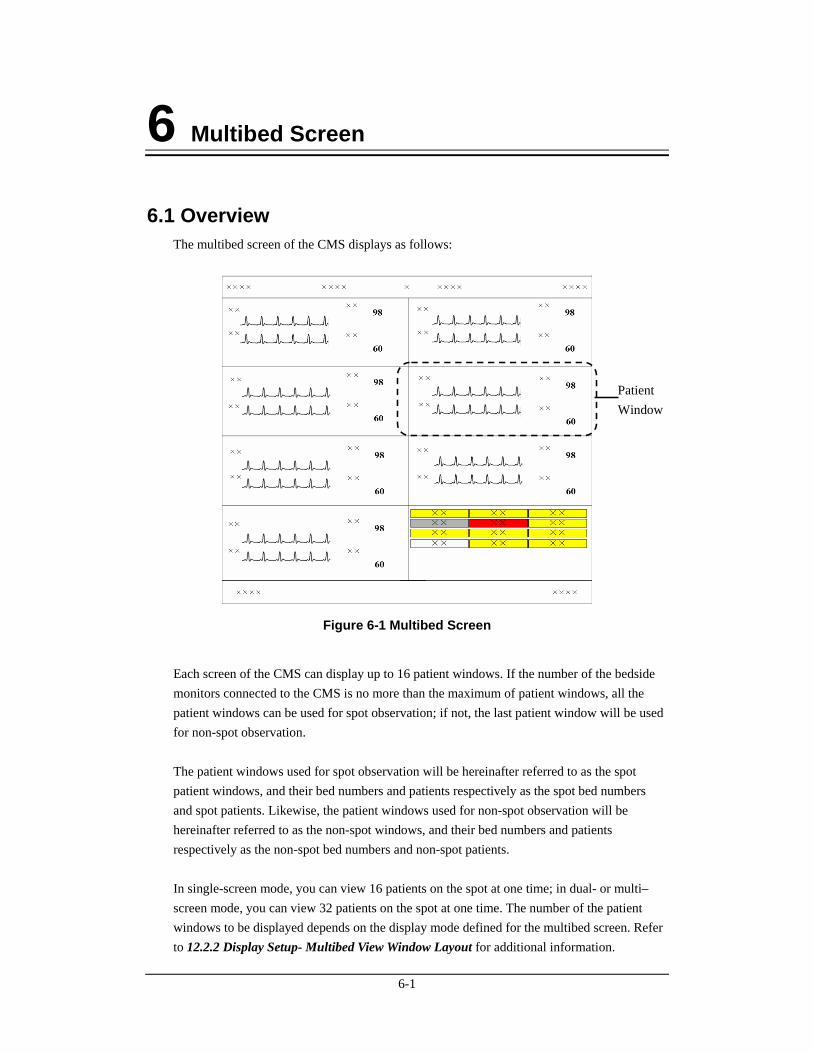
6-1
6 Multibed Screen
6.1 Overview The multibed screen of the CMS displays as follows:
Figure 6-1 Multibed Screen
Each screen of the CMS can display up to 16 patient windows. If the number of the bedside monitors connected to the CMS is no more than the maximum of patient windows, all the patient windows can be used for spot observation; if not, the last patient window will be used for non-spot observation. The patient windows used for spot observation will be hereinafter referred to as the spot patient windows, and their bed numbers and patients respectively as the spot bed numbers and spot patients. Likewise, the patient windows used for non-spot observation will be hereinafter referred to as the non-spot windows, and their bed numbers and patients respectively as the non-spot bed numbers and non-spot patients. In single-screen mode, you can view 16 patients on the spot at one time; in dual- or multi– screen mode, you can view 32 patients on the spot at one time. The number of the patient windows to be displayed depends on the display mode defined for the multibed screen. Refer to 12.2.2 Display Setup- Multibed View Window Layout for additional information.
Patient Window
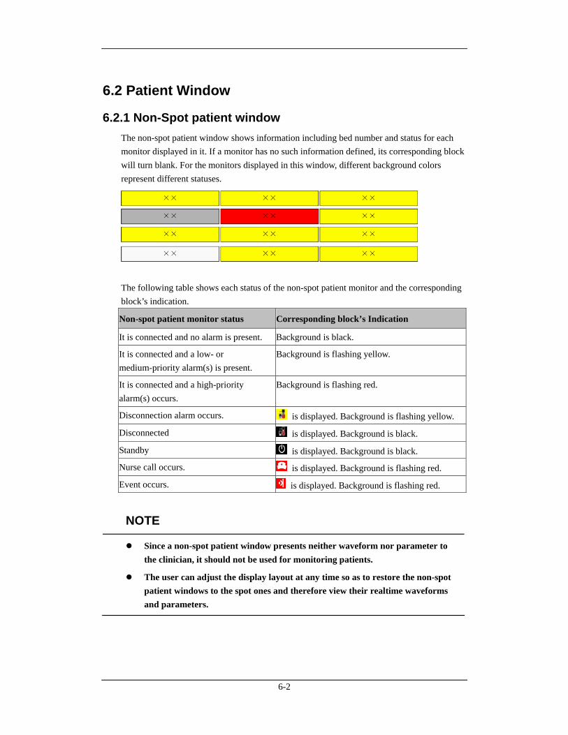
6-2
6.2 Patient Window
6.2.1 Non-Spot patient window The non-spot patient window shows information including bed number and status for each monitor displayed in it. If a monitor has no such information defined, its corresponding block will turn blank. For the monitors displayed in this window, different background colors represent different statuses.
The following table shows each status of the non-spot patient monitor and the corresponding block’s indication.
Non-spot patient monitor status Corresponding block’s Indication
It is connected and no alarm is present. Background is black.
It is connected and a low- or medium-priority alarm(s) is present.
Background is flashing yellow.
It is connected and a high-priority alarm(s) occurs.
Background is flashing red.
Disconnection alarm occurs. is displayed. Background is flashing yellow.
Disconnected is displayed. Background is black.
Standby is displayed. Background is black.
Nurse call occurs. is displayed. Background is flashing red.
Event occurs. is displayed. Background is flashing red.
NOTE
Since a non-spot patient window presents neither waveform nor parameter to the clinician, it should not be used for monitoring patients.
The user can adjust the display layout at any time so as to restore the non-spot patient windows to the spot ones and therefore view their realtime waveforms and parameters.
6-3
6.2.2 Spot Patient Windows In the process of monitoring, the spot patient window may stay in one of the following statuses:
“No Patient Admitted” indicates that no patient is admitted by the monitor corresponding to this patient window.
“Offline” indicates that this patient window has admitted a patient but its corresponding monitor may be turned off or disconnected from the CMS.
Patient Window in Monitoring Status: This patient window indicates that the monitor has admitted a patient. The corresponding bedside monitor is monitoring the patient and transferring the data to the CMS.
“STANDBY” indicates that the monitor or telemetry transmitter enters the standby mode.
“Idle sector. Click to admit a patient” indicates that the CMS can admit a new patient in this patient window.
The spot patient window may stay in other statuses. We will not introduce them in this manual.
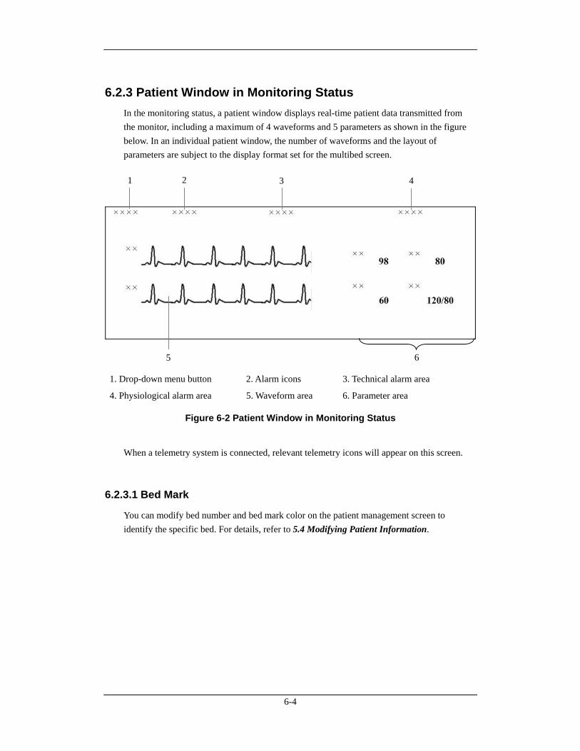
6-4
6.2.3 Patient Window in Monitoring Status In the monitoring status, a patient window displays real-time patient data transmitted from the monitor, including a maximum of 4 waveforms and 5 parameters as shown in the figure below. In an individual patient window, the number of waveforms and the layout of parameters are subject to the display format set for the multibed screen.
1. Drop-down menu button 2. Alarm icons 3. Technical alarm area
4. Physiological alarm area 5. Waveform area 6. Parameter area
Figure 6-2 Patient Window in Monitoring Status
When a telemetry system is connected, relevant telemetry icons will appear on this screen.
6.2.3.1 Bed Mark
You can modify bed number and bed mark color on the patient management screen to identify the specific bed. For details, refer to 5.4 Modifying Patient Information.
1 2 3 4
5 6
6-5
6.2.3.2 Drop-down Menu Button
Clicking this button will open a drop-down menu, in which you can perform these operations:
Monitor Silence: In the normal status, you can select it to silence current bedside monitor. In the case that the bedside monitor is silenced, you can select it to reactivate the bedside monitor’s audible prompts.
Audio Paused: In the normal status, you can select it to pause the alarm sound of the current bedside monitor for a period of time, which can be set on the monitor. Please refer to 8.7 Pausing Alarm Sound on Monitors for the patient window’s alarm sound pause.
Silence: You can select it to acknowledge the ongoing alarm. Both the monitor and corresponding patient window will enter the alarm silence status. Please refer to 8.6 Silencing Alarms for the patient window’s alarm silence status.
Alarm Pause: In the normal status, you can select it to pause all alarms of the current patient for a period of time, which can be set on the monitor. The default alarm pause time is 2 minutes. During the alarm pause, you can select it to reactivate the paused alarms.
STANDBY: If a telemetry transmitter is connected, in the normal monitoring status, you can select it to have an exit from displaying, analyzing, storing or recording the current patient’s physiological waveforms and data, with all alarms and sounds disabled and the icons of Nurse Call, Event, Battery Capacity and Received Signal Strength remained on the screen. In the Standby mode, you can select it to restore the normal monitoring mode. If a bedside monitor is connected, selecting it enables the bedside monitor to exit the state of standby.
Freeze: In the normal status, you can select it to freeze the dynamic waveforms with freeze time and time scales displayed in the waveform area. In the frozen status, clicking it will restore the dynamic waveforms.
Print: You can select it to start real-time printing.
Record: You can select it to start real-time recording.
ViewBed: You can select it to enter the “ViewBed” tab sheet.
Discharge Patient: You can select it to open the “Discharge” dialogue box.
Patient Mgmt.: You can select it to enter the “Patient Mgmt” Tab sheet.
Display Setup: You can select it to enter the “Display Setup” tab sheet.
Alarm Setup: You can select it to enter the “Alarm Setup” tab sheet
Big Numerics: In Big Numerics screen, major parameters are displayed in big numerics for better viewing. In this case, you can switch to normal screen by selecting “Normal Screen” from the drop-down menu.
Privacy Mode: Open the “Multibed” menu, select and set current bed or all beds to Privacy Mode.
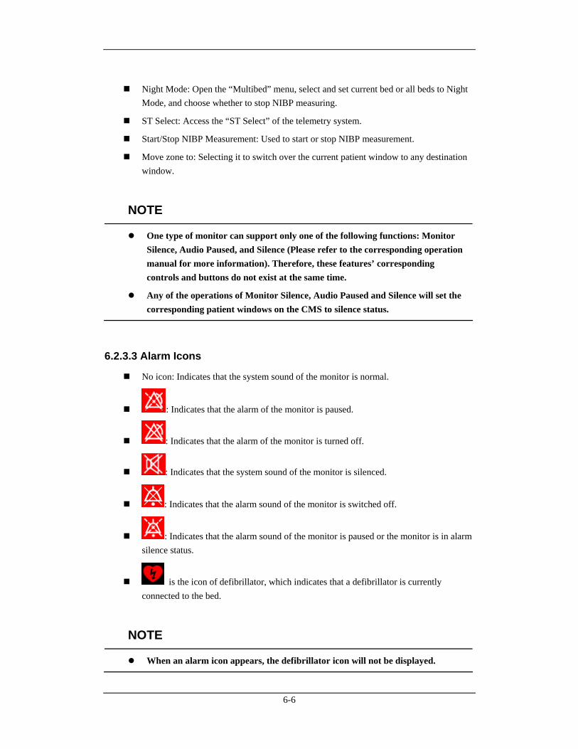
6-6
Night Mode: Open the “Multibed” menu, select and set current bed or all beds to Night Mode, and choose whether to stop NIBP measuring.
ST Select: Access the “ST Select” of the telemetry system.
Start/Stop NIBP Measurement: Used to start or stop NIBP measurement.
Move zone to: Selecting it to switch over the current patient window to any destination window.
NOTE
One type of monitor can support only one of the following functions: Monitor Silence, Audio Paused, and Silence (Please refer to the corresponding operation manual for more information). Therefore, these features’ corresponding controls and buttons do not exist at the same time.
Any of the operations of Monitor Silence, Audio Paused and Silence will set the corresponding patient windows on the CMS to silence status.
6.2.3.3 Alarm Icons
No icon: Indicates that the system sound of the monitor is normal.
: Indicates that the alarm of the monitor is paused.
: Indicates that the alarm of the monitor is turned off.
: Indicates that the system sound of the monitor is silenced.
: Indicates that the alarm sound of the monitor is switched off.
: Indicates that the alarm sound of the monitor is paused or the monitor is in alarm silence status.
is the icon of defibrillator, which indicates that a defibrillator is currently connected to the bed.
NOTE
When an alarm icon appears, the defibrillator icon will not be displayed.
6-7
6.2.3.4 Technical Alarm Area
The Technical Alarm Area displays:
The technical alarms and messages coming from monitor or CMS;
The work mode and initiated events of a defibrillator.
When multiple messages occur, they will be displayed circularly.
6.2.3.5 Physiological Alarm Area
The physiological alarm area displays:
Physiological alarms coming from monitor;
The message indicating the alarm or physiological state. For example, “Alarm Pause”, “CPB Mode”.
When there are multiple messages, the messages will be displayed circularly. When alarms are latched, alarm time is displayed; otherwise, the alarm time is not displayed.
NOTE
Different alarm priorities are indicated by different background colors in the alarm area. Refer to Part 8.2 Alarm Mode for details.
You can view all physiological or technical alarms by positioning the mouse pointer inside the physiological or technical alarm area and pressing the left mouse button.
For unknown technical alarms, the message is “XX Technical Alarm”, XX representing high, medium or low.
For unknown physiological alarms, the message is “XX Phys. Alarm”, XX representing high, medium or low.
6.2.3.6 Waveform Area
Display waveforms transmitted from the monitor.
Display the patient’s name above the first waveform.
When one or all lethal arrhythmia alarms are set to off, a message of “Lethals Off” will be displayed under the first ECG waveform.
When the nurse call and/or event function of the telemetry system is switched off, a message will display the status under the first ECG waveform.
If a patient’s paced status has not been set on the monitor, the icon will flash in
the waveform area when pacer pulse is detected. Click the icon, the “Patient Mgmt” sheet will pop up. The item of “Paced” can be configured there.
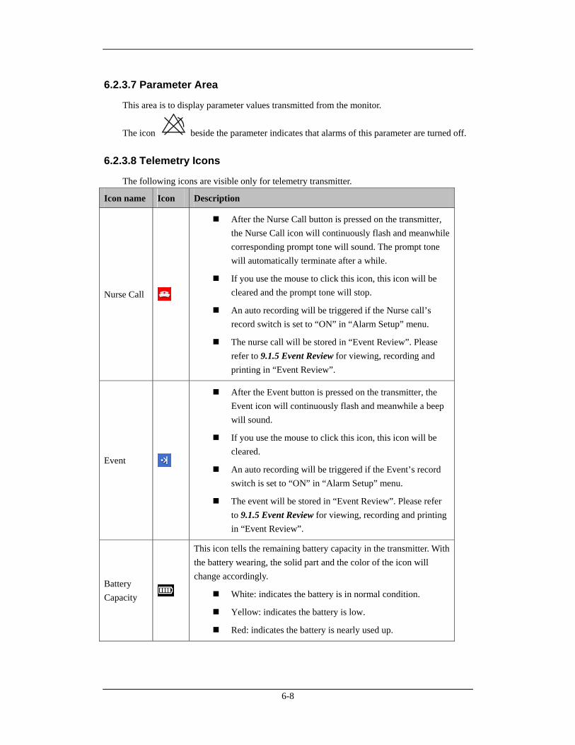
6-8
6.2.3.7 Parameter Area
This area is to display parameter values transmitted from the monitor.
The icon beside the parameter indicates that alarms of this parameter are turned off.
6.2.3.8 Telemetry Icons
The following icons are visible only for telemetry transmitter.
Icon name Icon Description
Nurse Call
After the Nurse Call button is pressed on the transmitter, the Nurse Call icon will continuously flash and meanwhile corresponding prompt tone will sound. The prompt tone will automatically terminate after a while.
If you use the mouse to click this icon, this icon will be cleared and the prompt tone will stop.
An auto recording will be triggered if the Nurse call’s record switch is set to “ON” in “Alarm Setup” menu.
The nurse call will be stored in “Event Review”. Please refer to 9.1.5 Event Review for viewing, recording and printing in “Event Review”.
Event
After the Event button is pressed on the transmitter, the Event icon will continuously flash and meanwhile a beep will sound.
If you use the mouse to click this icon, this icon will be cleared.
An auto recording will be triggered if the Event’s record switch is set to “ON” in “Alarm Setup” menu.
The event will be stored in “Event Review”. Please refer to 9.1.5 Event Review for viewing, recording and printing in “Event Review”.
Battery Capacity
This icon tells the remaining battery capacity in the transmitter. With the battery wearing, the solid part and the color of the icon will change accordingly.
White: indicates the battery is in normal condition.
Yellow: indicates the battery is low.
Red: indicates the battery is nearly used up.
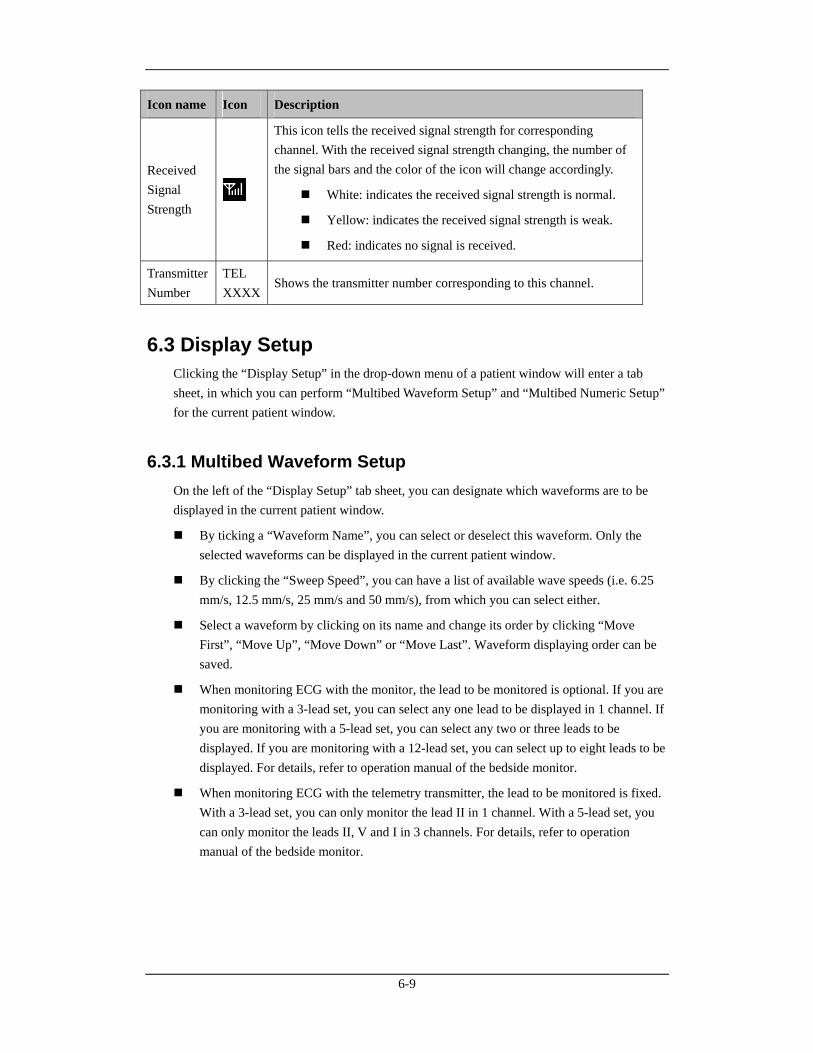
6-9
Icon name Icon Description
Received Signal Strength
This icon tells the received signal strength for corresponding channel. With the received signal strength changing, the number of the signal bars and the color of the icon will change accordingly.
White: indicates the received signal strength is normal.
Yellow: indicates the received signal strength is weak.
Red: indicates no signal is received.
Transmitter Number
TEL XXXX
Shows the transmitter number corresponding to this channel.
6.3 Display Setup Clicking the “Display Setup” in the drop-down menu of a patient window will enter a tab sheet, in which you can perform “Multibed Waveform Setup” and “Multibed Numeric Setup” for the current patient window.
6.3.1 Multibed Waveform Setup On the left of the “Display Setup” tab sheet, you can designate which waveforms are to be displayed in the current patient window.
By ticking a “Waveform Name”, you can select or deselect this waveform. Only the selected waveforms can be displayed in the current patient window.
By clicking the “Sweep Speed”, you can have a list of available wave speeds (i.e. 6.25 mm/s, 12.5 mm/s, 25 mm/s and 50 mm/s), from which you can select either.
Select a waveform by clicking on its name and change its order by clicking “Move First”, “Move Up”, “Move Down” or “Move Last”. Waveform displaying order can be saved.
When monitoring ECG with the monitor, the lead to be monitored is optional. If you are monitoring with a 3-lead set, you can select any one lead to be displayed in 1 channel. If you are monitoring with a 5-lead set, you can select any two or three leads to be displayed. If you are monitoring with a 12-lead set, you can select up to eight leads to be displayed. For details, refer to operation manual of the bedside monitor.
When monitoring ECG with the telemetry transmitter, the lead to be monitored is fixed. With a 3-lead set, you can only monitor the lead II in 1 channel. With a 5-lead set, you can only monitor the leads II, V and I in 3 channels. For details, refer to operation manual of the bedside monitor.
6-10
NOTE
When a patient is discharged, the multibed settings in “Waveform Selection and Order” are saved. The waveforms will be shown as per the same configurations by default when a patient is admitted next time.
If you discharge a patient and set the bed to an idle sector, the multibed settings in “Waveform Selection and Order” are cleared, and the waveform configurations restore to the system defaults.
6.3.2 Multibed Numeric Setup Default numeric group cannot be modified or deleted. To change the parameters to be displayed and their order in the current patient window, you can follow this procedure:
1. Click on the “New Group” button, and “New Group 1” will appear under “Default Group”.
2. Select the “New Group 1” to open the “Select & Order” list.
3. Select a parameter from the “Select & Order” list. The “Numeric Preview” area will show the parameter you have just selected. A maximum of 5 parameters are allowed to be selected.
4. Select a parameter by clicking on its name and change its order by clicking “Move First”, “Move Up”, “Move Down” or “Move Last”.
5. Click the “Save Group” button and then select the “New Group 1”. The current patient will show parameters according to the setup of “New Group 1”.
To delete the “New Group 1”, you can select the “New Group 1” and then click the “Delete Group” button.
NOTE
When a patient is discharged, the selection of the numeric group is saved. The numeric group will be shown as per the same configurations by default when a patient is admitted next time.
If you discharge a patient and set the bed to an idle sector, the selection of the numeric group is cleared, and the waveform configurations restore to the system defaults.
7-1
7 Viewbed
7.1 Overview The CMS allows you to view a single patient through the “ViewBed” screen, in which you will have an enlarged view of that single patient’s information, waveforms and values. In this screen, you can freeze waveforms, review dynamic short trends, view multi-lead ECG waveforms and record waveforms, etc. To access the “ViewBed” screen, follow the instructions below:
For a spot patient, click the left mouse button in its corresponding patient window. The “ViewBed” screen for that patient will open.
For a non-spot patient, click on its corresponding block in the non-spot patient window. The “ViewBed” screen for that patient will open.
When the “ViewBed” window is open, you can switch among different patients by clicking in the patient window of a spot patient, or clicking on the block of a non-spot patient, or selecting another bed number in the bed drop-down list of single bed window.
NOTE
In the single-screen mode, the CMS uses the lower half screen to accommodate the “ViewBed” screen.
In the dual- or multi- screen mode, the CMS uses the secondary display screen to accommodate the “ViewBed” screen.
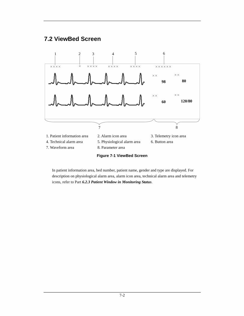
7-2
7.2 ViewBed Screen
×××× ×××××××××××
××
98
××
60
××
80
××
120/80
××××××××
1. Patient information area 2. Alarm icon area 3. Telemetry icon area 4. Technical alarm area 5. Physiological alarm area 6. Button area 7. Waveform area 8. Parameter area
Figure 7-1 ViewBed Screen
In patient information area, bed number, patient name, gender and type are displayed. For description on physiological alarm area, alarm icon area, technical alarm area and telemetry icons, refer to Part 6.2.3 Patient Window in Monitoring Status.
1 2 3 5
7 8
4 6
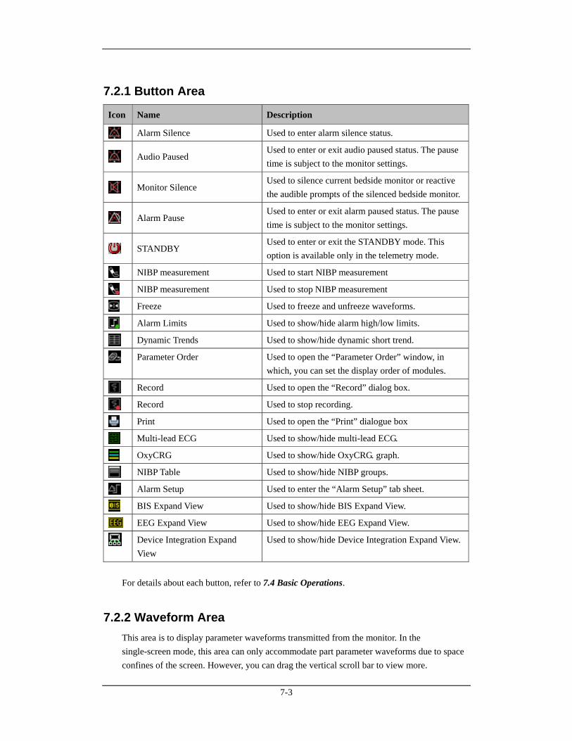
7-3
7.2.1 Button Area
Icon Name Description
Alarm Silence Used to enter alarm silence status.
Audio Paused Used to enter or exit audio paused status. The pause time is subject to the monitor settings.
Monitor Silence Used to silence current bedside monitor or reactive the audible prompts of the silenced bedside monitor.
Alarm Pause Used to enter or exit alarm paused status. The pause time is subject to the monitor settings.
STANDBY Used to enter or exit the STANDBY mode. This option is available only in the telemetry mode.
NIBP measurement Used to start NIBP measurement
NIBP measurement Used to stop NIBP measurement
Freeze Used to freeze and unfreeze waveforms.
Alarm Limits Used to show/hide alarm high/low limits.
Dynamic Trends Used to show/hide dynamic short trend.
Parameter Order Used to open the “Parameter Order” window, in which, you can set the display order of modules.
Record Used to open the “Record” dialog box.
Record Used to stop recording.
Print Used to open the “Print” dialogue box
Multi-lead ECG Used to show/hide multi-lead ECG.
OxyCRG Used to show/hide OxyCRG. graph.
NIBP Table Used to show/hide NIBP groups.
Alarm Setup Used to enter the “Alarm Setup” tab sheet.
BIS Expand View Used to show/hide BIS Expand View.
EEG Expand View Used to show/hide EEG Expand View.
Device Integration Expand View
Used to show/hide Device Integration Expand View.
For details about each button, refer to 7.4 Basic Operations.
7.2.2 Waveform Area This area is to display parameter waveforms transmitted from the monitor. In the single-screen mode, this area can only accommodate part parameter waveforms due to space confines of the screen. However, you can drag the vertical scroll bar to view more.
7-4
7.2.3 Parameter Area This area is to display parameter values transmitted from the monitor. Each parameter module occupies a rectangular area, which is hereafter called parameter window. In the single-screen mode, this area can only accommodate part parameter values due to space confines of the screen. However, you can drag the vertical scroll bar to view more. Click in a parameter window. The border of the window will highlight when the window is selected. Clicking on it again will enter the “Parameter Setup” tab sheet. For details, refer to Part 7.3 Parameter Setup.
NOTE
The waveforms and parameters are consistent between the CMS and the monitor.
If you change the display order of waveforms and parameters on the monitor, the display order of waveforms and parameters on the CMS will not change automatically. Vice versa.
In case a module of the monitor is turned off or a parameter is not being monitored, its corresponding waveforms and parameters displayed on the CMS’s screen will disappear at the same time.
7.3 Parameter Setup Click in a parameter window, and the border of this window will appear highlighted. Clicking again will open the “Parameter Setup” window. The current tab sheet depends on the parameter window you have selected. For example, if you click in the ECG parameter window, the Parameter Setup window will open, with the “ECG” tab sheet at the front. In this tab sheet, you can set alarm, record switch and sweep speed for all parameters of ECG, SpO2, C.O., etc. For details on alarms, refer to Part 8.4 Alarm Setup.
7-5
7.4 Basic Operations
7.4.1 Alarm Setup
Clicking the button will enter the “Alarm Setup” tab sheet, in which you can set
parameter alarms, arrhythmia alarms, arrhythmia alarm threshold and alarm-related aspect. For details, refer to 8.4 Alarm Setup.
7.4.2 Silencing Alarms on Monitors
By clicking the Silence icon , you can acknowledge the ongoing alarms. Both the
monitor and telemetry transmitter enter the alarm silenced status. The corresponding patient window on the CMS also enters the alarm silenced status. Please refer to 8.6 Silencing Alarms on Monitors for the patient window’s alarm silence status.
7.4.3 Pausing Alarm Sound on Monitors
By clicking the Audio Paused icon , you can pause the alarm sound of a bedside monitor.
The corresponding patient window on the CMS will enter the alarm silenced status. You can
also release the audio paused status by clicking the Audio Paused icon again.
7.4.4 Silencing a Bedside Monitor
By clicking the Monitor Silence icon , you can silence current bedside monitor. The
corresponding patient window on the CMS will enter the alarm silenced status. You can reactivate the audible prompts of the silenced bedside monitor by clicking the Monitor
Silence icon again.
7.4.5 Pausing Alarms on Monitors
By clicking the Alarm Pause icon , you can pause all alarms of the current patient for a
period of time, which is subject to the bedside monitor settings. The alarm pause time for the telemetry transmitter is fixed to 2 minutes. After the alarm pause time ends, the system will automatically release the alarm pause. You can also release the alarm pause by clicking the Alarm Pause icon again.
7-6
7.4.6 STANDBY
The STANDBY icon is applicable to the telemetry transmitter only. Clicking this icon
will have the current patient to enter the STANDBY mode. In the STANDBY mode, you can click this icon again or click any place in the ViewBed to exit the STANDBY mode. For details about the STANDBY mode, refer to the manual of the telemetry monitoring system.
7.4.7 Controlling a Bedside Monitor to Exit STANDBY If a bedside monitor is in the state of STANDBY, click any place in the ViewBed window. Then a dialog box of prompt information will pop up. Select “Yes” in the dialog box and the monitor will exit the state of standby and start normal monitoring.
NOTE
The CMS can control the monitor to exit STANDBY mode only when the monitor supports this function.
7.4.8 NIBP Measurement
Once the icon is clicked, the corresponding bedside monitor will start a NIBP
measurement. During measuring process, this icon turns to be . At this time, you can click
this icon to stop the measurement. This icon changes accordingly when the bedside monitor starts or stops a NIBP measurement.
WARNING
Before starting an NIBP measurement by a bedside monitor at the CMS side, be sure that patient type set on the bedside monitor is correct and NIBP cuff applied is proper.
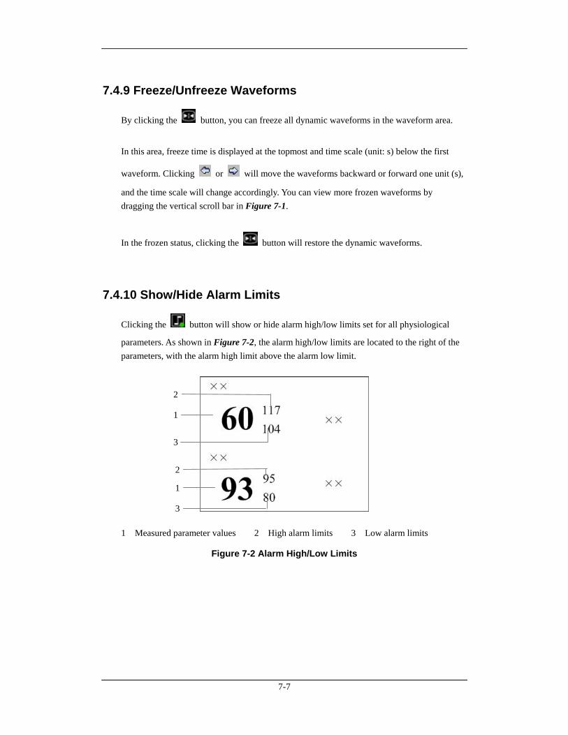
7-7
7.4.9 Freeze/Unfreeze Waveforms
By clicking the button, you can freeze all dynamic waveforms in the waveform area.
In this area, freeze time is displayed at the topmost and time scale (unit: s) below the first
waveform. Clicking or will move the waveforms backward or forward one unit (s),
and the time scale will change accordingly. You can view more frozen waveforms by dragging the vertical scroll bar in Figure 7-1.
In the frozen status, clicking the button will restore the dynamic waveforms.
7.4.10 Show/Hide Alarm Limits
Clicking the button will show or hide alarm high/low limits set for all physiological
parameters. As shown in Figure 7-2, the alarm high/low limits are located to the right of the parameters, with the alarm high limit above the alarm low limit.
1 Measured parameter values 2 High alarm limits 3 Low alarm limits
Figure 7-2 Alarm High/Low Limits
1
1
2
2
3
3
7-8
7.4.11 Show/Hide Dynamic Trends
Clicking the button will show or hide dynamic short trends for each physiological
parameter. For details on dynamic short trend, refer to Part 9.1.1 Dynamic Short Trend.
7.4.12 Parameter Order
Clicking the button will open a dialog box, in which you can set the waveforms and
parameters displaying order. The parameters to be set depend on the configuration of the monitor. Select a parameter and then click “Move Up”, “Move Down”, “Move First” or “Move Last” to adjust its position. Its waveforms and digitals will change their positions accordingly. Clicking the “Default” button will restore the default display order of modules. The settings of display order can be saved.
NOTE
When a patient is discharged, the configuration of parameter order is saved. The parameters will be shown as per the same configurations when a patient is admitted next time.
If you discharge a patient and set the bed to an idle sector, the configuration of parameter order is cleared, and the waveform configuration restores to the system defaults.
7.4.13 Record
Clicking the button will open the Record dialog box, in which you can select up to two
waveforms. In case that the recorder is unusable or no recorder is connected, this button is disabled. In the frozen status, the recorded waveforms and parameters are the waveforms and parameters recorded at time of freezing but not at current time. Please refer to 11.1.3 Recording Control about the settings of recording general options.
7-9
7.4.14 Print Printing in Real-time
Click the button, the “Print Setup” dialog box will pop up. In this dialog box, you can select the waveforms to be printed. In the case that the printer is unusable or no printer is connected, this button will be disabled. Please refer to 11.2.4 Printing Control about the settings of printing general options.
Printing 12-lead ECG
When performing 12-lead ECG monitoring and 12-lead ECG analysis using a bedside
monitor, you can press the button to display the 12-lead ECG waveforms. Then click the button, the “Print Setup” dialog box will pop up. In this dialog box, you can set the
waveform layout as 12*1, 6*2 or 3*4. In the case that the printer is unusable or no printer is connected, this button will be disabled.
Printing Multi-lead ECG
When a patient is under 5-lead ECG monitoring by a bedside monitor, select the button to display the multi-lead ECG waveforms. Then click the button, to print ECG waveforms. In the case that the printer is unusable or no printer is connected, this button will be disabled.
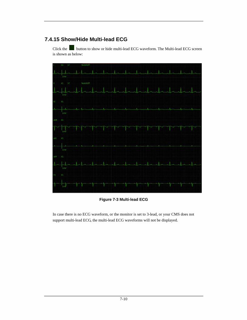
7-10
7.4.15 Show/Hide Multi-lead ECG Click the button to show or hide multi-lead ECG waveform. The Multi-lead ECG screen is shown as below:
Figure 7-3 Multi-lead ECG
In case there is no ECG waveform, or the monitor is set to 3-lead, or your CMS does not support multi-lead ECG, the multi-lead ECG waveforms will not be displayed.
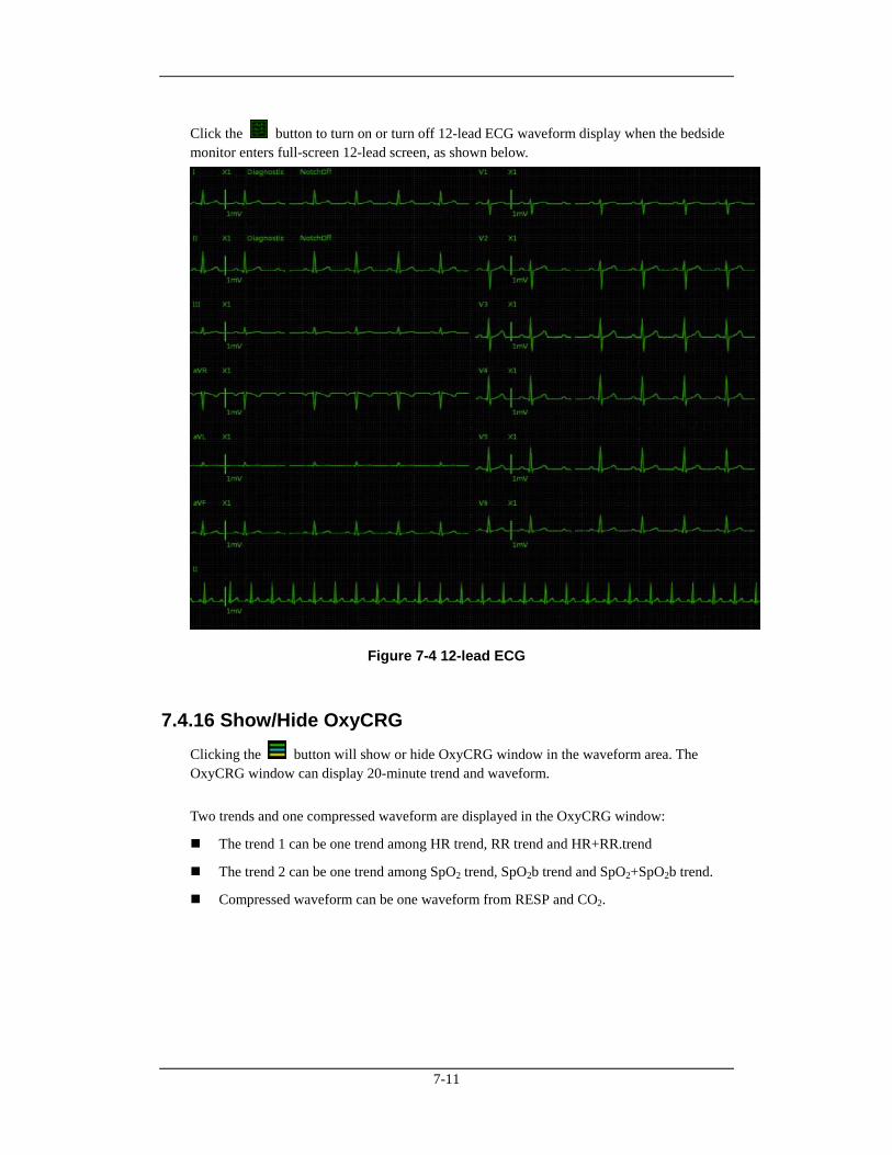
7-11
Click the button to turn on or turn off 12-lead ECG waveform display when the bedside monitor enters full-screen 12-lead screen, as shown below.
Figure 7-4 12-lead ECG
7.4.16 Show/Hide OxyCRG Clicking the button will show or hide OxyCRG window in the waveform area. The OxyCRG window can display 20-minute trend and waveform. Two trends and one compressed waveform are displayed in the OxyCRG window:
The trend 1 can be one trend among HR trend, RR trend and HR+RR.trend
The trend 2 can be one trend among SpO2 trend, SpO2b trend and SpO2+SpO2b trend.
Compressed waveform can be one waveform from RESP and CO2.
7-12
In OxyCRG window, the operations are shown as following:
Click “OxyCRG Review” button to show the OxyCRG review screen.
Click “Auto Scale” button, and the scale will be automatically adjusted to its most suitable state according to the current trend or waveform.
Click “Zoom” to set the time range of the currently displayed trends and waveform.
Click “Setup” button to set which trend or waveform to be displayed in the OxyCRG window, and to manually set the scale.
Click “Record” button to record OxyCRG graph.
Click “Print” button to print OxyCRG gragh.
7.4.17 Show/Hide NIBP Table
Clicking the button will show or hide NIBP table in the waveform area. Each
measurement includes Measure Time, NIBP values and PR.
7.4.18 Show/Hide BIS Expand View
You can click button to show or hide BIS Expand View. In BIS Expand View, you can
select to view EEG waveforms, BIS trend and DSA graph. This button is enabled only when networked monitor supports BISx4 monitoring; otherwise, this button is disabled.
7.4.19 Show/Hide EEG Expand View You can click button to show or hide EEG Expand View. In EEG Expand View, you can select to view EEG waveforms, EEG parameter, EEG trend, CSA and DSA.
7.4.20 Show/Hide Device Integration Expand View
Clicking the button will show or hide Device Integration Expand View. This button is
enabled only when networked monitor supports device integration; otherwise, this button is disabled. All text in Device Integration Expand View appears in white. You can select to view an individual device or all devices in the Device Integration Expand View:
Click one of the individual device tabs and access its corresponding tab sheet. Each tab sheet provides “Parameter Display” and “Alarm Setup” button.
Parameter Display: You can use the button to select the desired parameters to be displayed.
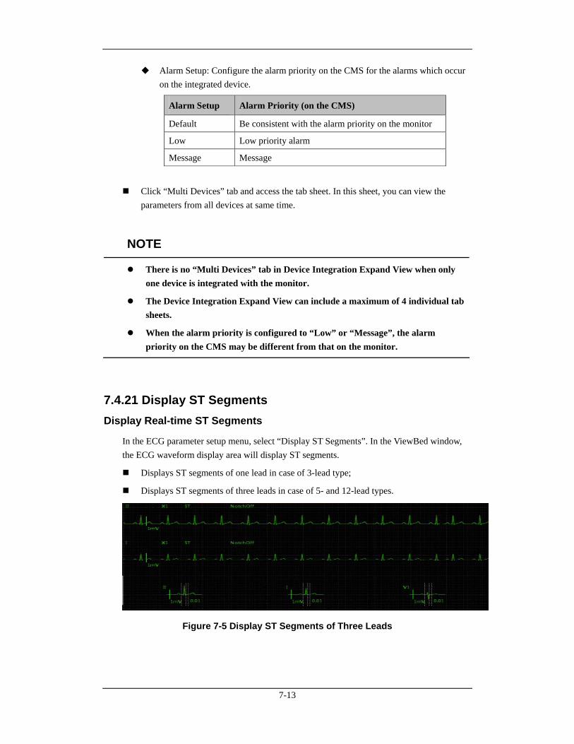
7-13
Alarm Setup: Configure the alarm priority on the CMS for the alarms which occur on the integrated device.
Alarm Setup Alarm Priority (on the CMS)
Default Be consistent with the alarm priority on the monitor
Low Low priority alarm
Message Message
Click “Multi Devices” tab and access the tab sheet. In this sheet, you can view the parameters from all devices at same time.
NOTE
There is no “Multi Devices” tab in Device Integration Expand View when only one device is integrated with the monitor.
The Device Integration Expand View can include a maximum of 4 individual tab sheets.
When the alarm priority is configured to “Low” or “Message”, the alarm priority on the CMS may be different from that on the monitor.
7.4.21 Display ST Segments Display Real-time ST Segments
In the ECG parameter setup menu, select “Display ST Segments”. In the ViewBed window, the ECG waveform display area will display ST segments.
Displays ST segments of one lead in case of 3-lead type;
Displays ST segments of three leads in case of 5- and 12-lead types.
Figure 7-5 Display ST Segments of Three Leads
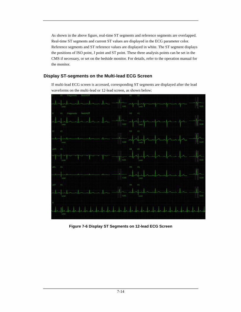
7-14
As shown in the above figure, real-time ST segments and reference segments are overlapped. Real-time ST segments and current ST values are displayed in the ECG parameter color. Reference segments and ST reference values are displayed in white. The ST segment displays the positions of ISO point, J point and ST point. These three analysis points can be set in the CMS if necessary, or set on the bedside monitor. For details, refer to the operation manual for the monitor.
Display ST-segments on the Multi-lead ECG Screen
If multi-lead ECG screen is accessed, corresponding ST segments are displayed after the lead waveforms on the multi-lead or 12-lead screen, as shown below:
Figure 7-6 Display ST Segments on 12-lead ECG Screen
8-1
8 Alarm Control
8.1 Alarm Structure Alarms, triggered by a vital sign that appears abnormal or by technical problems of the monitor, are sent to the CMS by the monitors and then indicated to the users by the CMS. Most of the alarms originally come from the monitors. The alarms coming from the CMS itself are displayed in the patient window’s technical alarm area or system alarm area on the upper screen. Please refer to Appendix B Central Monitoring System Alarms for the alarm messages. By nature, the alarms are classified into two categories:
Physiological alarms, and
Technical alarms.
By severity, the alarms are classified into:
High priority alarms,
Medium priority alarms, and
Low priority alarms
NOTE
For details on alarms, refer to the monitor’s operation manual.
8.2 Alarm Mode The CMS gives audible and visual alarms in compliance with international standards.
WARNING
The audible and visual alarms given by the CMS comply with the IEC 60601-1-8 standard. The hospital or institution employing the use of the CMS should give adequate training to the operators.
8-2
8.2.1 Audible Alarms This system has three choices of alarm tones and patterns: ISO, Mode 1 and Mode 2. For each pattern, the alarm tones identify the alarm levels as follows:
ISO pattern:
High level alarms: triple+double+triple+double beep.
Medium level alarms: triple beep.
Low level alarms: single beep.
Mode 1:
High level alarms: high-pitched triple beep.
Medium level alarms: double beep.
Low level alarms: low-pitched single beep.
Mode 2:
High level alarms: high-pitched triple beep.
Medium level alarms: double beep.
Low level alarms: low-pitched single beep.
NOTE
When multiple patients have alarms of different priorities at the same time, the system will select the alarms of highest priorities and give alarm tones accordingly.
When the system is set to “silence”, giving alarm tones is disabled. In case of a new alarm, the silenced state will be released automatically. You can also release the silenced state manually. For details, refer to 8.10 CMS System Silence.
In the “General Setup” screen of “System Setup”, when the alarm volume is set to 0, the CMS alarm sound is turned off., and the CMS will switch off the alarm tone permanently and give no audible alarm even if a new alarm occurs. Be careful to configure the alarm volume to 0.
8.2.2 Reminder Tone In the status of CMS system silence or audio alarm off, the CMS can give a kind of reminder tone in case of an active alarm condition. The Reminder Tone is same as the highest alarm tone. You can set the reminder volume in the “General Setup” tab sheet. You can set the reminder interval and switch on/off the reminder tone in the “Admin Setup” menu.
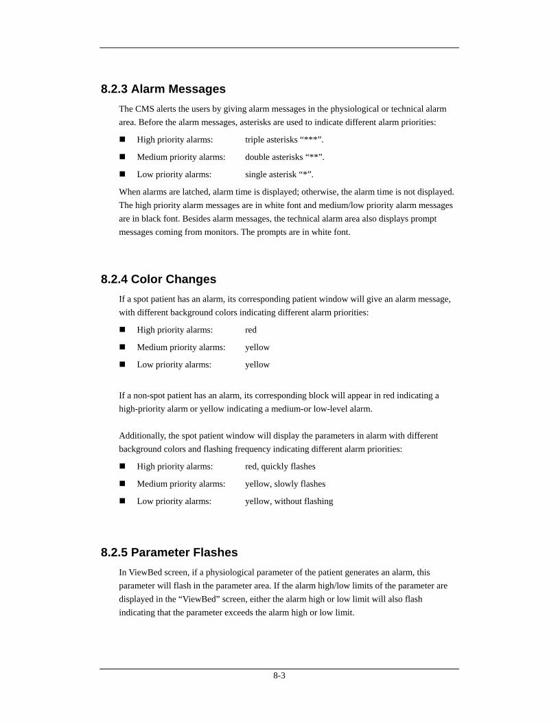
8-3
8.2.3 Alarm Messages The CMS alerts the users by giving alarm messages in the physiological or technical alarm area. Before the alarm messages, asterisks are used to indicate different alarm priorities:
High priority alarms: triple asterisks “***”.
Medium priority alarms: double asterisks “**”.
Low priority alarms: single asterisk “*”.
When alarms are latched, alarm time is displayed; otherwise, the alarm time is not displayed. The high priority alarm messages are in white font and medium/low priority alarm messages are in black font. Besides alarm messages, the technical alarm area also displays prompt messages coming from monitors. The prompts are in white font.
8.2.4 Color Changes If a spot patient has an alarm, its corresponding patient window will give an alarm message, with different background colors indicating different alarm priorities:
High priority alarms: red
Medium priority alarms: yellow
Low priority alarms: yellow
If a non-spot patient has an alarm, its corresponding block will appear in red indicating a high-priority alarm or yellow indicating a medium-or low-level alarm. Additionally, the spot patient window will display the parameters in alarm with different background colors and flashing frequency indicating different alarm priorities:
High priority alarms: red, quickly flashes
Medium priority alarms: yellow, slowly flashes
Low priority alarms: yellow, without flashing
8.2.5 Parameter Flashes In ViewBed screen, if a physiological parameter of the patient generates an alarm, this parameter will flash in the parameter area. If the alarm high/low limits of the parameter are displayed in the “ViewBed” screen, either the alarm high or low limit will also flash indicating that the parameter exceeds the alarm high or low limit.
8-4
8.3 Alarm Volume By clicking “System Setup” then “General Setup”, you can enter a tab sheet. The CMS provides up to 11 volume levels, increasing from 0 to 10. You can drag the volume control key to your desired volume. While dragging the volume control key, the corresponding sound will also be played. The alarm volume can be configured in the range from Minimum Alarm Volume to 10. Please refer to 12.2.3 Alarm - Minimum Alarm Volume. In the “General Setup” tab, you can set high alarm volume. High alarm volume can be set equal to or louder than the alarm volume. The options are “alarm volume +0”, “alarm volume+1”and “alarm volume+2”. When a high level alarm occurs, the alarm will sound with the specified high alarm volume. For example, if the high alarm volume is set to “alarm volume+1”, and the current level of alarm volume is 5, then the high alarm volume is 6.
NOTE
If the alarm volume is set to 0, the system information area displays alarm audio
off icon .
If high alarm volume level is greater than 10, the monitor will sound it in the volume of 10.
8.4 Alarm Setup In either the “Parameter Setup” or “Alarm Setup” tab sheet, you can define alarm switch, alarm high/low limits and alarm priority for each parameter.
8.4.1 Parameter Setup Tab Sheet Click in a parameter window. The border of the window will appear highlighted when the window is selected. Clicking again will enter a tab sheet. Take the ECG module as an example; you can set the HR alarm switch, limit and priority.
8-5
NOTE
When the “Alarm Setup” at “Remote Control Settings” menu is ticked, the settings of the parameter alarm switch, limit and level are controlled bidirectionally. For example, if the alarm switch of a parameter is set to “Off”, the alarm switch of this parameter will change to “Off” on the monitor. Refer to 12.2.8 Other for the details of remote alarm setup.
When you change the alarm limits of the monitor via the CMS, make sure that the alarm limits settings are appropriate for your patient. Setting alarm limits to extreme values may cause the alarm system to become ineffective.
Default: Click this button to restore CMS-related settings to factory default.
Alarm Setup: Click this button to enter the Alarm Setup tab sheet. Refer to Section 8.4.2 Alarm Setup Tab Sheet Alarm Setup Tab Sheet for details.
For telemetry transmitter, the parameter setup tab sheet is different. For details, refer to the manual of telemetry monitoring system.
8.4.2 Alarm Setup Tab Sheet
Clicking the button in the “ViewBed” screen will enter the “Alarm Setup” tab sheet, in
which you can set parameter alarms, arrhythmia alarms, arrhythmia alarm threshold and other aspect of alarms.
8.4.2.1 Setting Parameter Alarm
In the “Parameter Alarm Settings” tab sheet, you can set the alarm properties of ECG, HR, SpO2 and other parameters. Take the HR as an example; you can use the keyboard to modify its alarm high/low limits by clicking “HIGH LIMIT” or “LOW LIMIT”, as well as use the mouse to make a selection by clicking “Alarm Priority”, “Activation State”, “Record On Alarm” or “Print On Alarm”.
8-6
8.4.2.2 Setting Arrhythmia Alarms
In the “Arrhythmia Alarms” tab sheet, the alarm for asystole, tachy and other kinds of arrhythmia can be set here.
Alarm priority: The alarm level can be set to “High”, “Med”, “Low” or “Message”. Specifically, the “Message” level only has text, without the indication by audio, background color and ‘*’.
Activation state: The activation state of each arrhythmia can be set individually. In addition, the activation state of some arrhythmias can be set as a whole with the buttons of “All Alarm On”, “All Alarm Off” and “Lethals Only”. If click “Lethals Only” button, only the lethal arrhythmia alarms are set to “ON” and other alarms are set to “OFF”; if click “All Alarm On”, all arrhythmia alarms are set to “ON”; if click “All Alarm Off”, all arrhythmia alarms are set to “OFF”.
Record, Print On Alarm: Set the switch of record in real-time and print in real-time when arrhythmia alarms occur..
NOTE
If a bedside monitor is connected and the “Lethal Arrh. Off” item in its “Admin Setup” menu is set to “Disable”, the “All Alarm Off” button in the arrhythmia alarm settings of the CMS is inactive.
If a telemetry monitoring system is connected and the “Lethal Arr. Off” item in “Telemetry” sheet under “Admin Setup” menu is set to “Disable”, the “All Alarm Off” button in the “Arrhythmia Alarm” of the CMS is inactive.
8.4.2.3 Setting Arrh. Threshold
The threshold of PVCs high limit, tachy and others can be set in “Arrh. Threshold Setup” sheet.
8.4.2.4 Others
In “Others” tab sheet, the alarm latch can be set here. Please refer to 8.9 Latching Alarms for details.
8-7
8.5 Pausing Alarms For the monitors supporting bidirectional control of alarm pause, you can click the Alarm
Pause icon in the viewbed screen or Alarm Pause in the drop-down menu in the
multibed screen to pause all alarms of current monitor for a period of time, which can be set on the monitor. After alarm pause time ends, the system will automatically release the alarm
pause. You can also release the alarm pause by clicking the icon or Alarm Pause in the
drop-down menu again. You can enable or disable the remote alarm control function on the CMS. When remote alarm
control is disabled, the icon is inactive and the “Alarm Pause” control is not available in
the drop-down menu in the multibed screen. Refer to Section 12.2.8 Other to see how to enable or disable the remote alarm control function.
8.6 Silencing Alarms For the monitors supporting bidirectional control of alarm silence, you can enter the status of Silence through following ways:
In the CMS viewbed screen, click the Silence icon .
In the multibed screen, you can click the right button of mouse when the cursor is in the window where the patient needs the setting of Silence, or select the option ‘Silence’ in its drop-down menu.
When Silence is selected, both the monitor and corresponding patient window on the CMS will enter the alarm silenced status: after the physiological alarm is silenced, √ appears before the alarm message; for some technical alarms, √ appears before the alarm message after the alarm is silenced; for some technical alarms, the alarm message changes to prompt message after the alarm is silenced; for some other technical alarms, the alarm message is cleared after the alarm is silenced. As for the monitor’s alarm silenced status and the classification of technical alarms, please refer to the monitor’s Operator’s Manual. The alarm silenced status will be automatically cancelled when a new alarm occurs. You can enable or disable the remote alarm control function on the CMS. When remote alarm
control is disabled, the icon is inactive and the “Silence” control is not available in the
drop-down menu in the multibed screen. Refer to Section 12.2.8 Other to see how to enable or disable the remote alarm control function.
8-8
8.7 Pausing Alarm Sound on Monitors For the monitors supporting bidirectional control of alarm sound pause, you can enter the status of Audio Paused of bedside monitor through following ways:
In the CMS viewbed screen, click the Audio Paused icon .
In the multibed screen, you can click the right button of mouse when the cursor is in the window where the patient needs the setting of Audio Paused, or select the option ‘Audio Paused’ in its drop-down menu.
When Audio Paused is selected, the sound of technical alarms and physiological alarms on the monitor will be paused, but the alarm lamps and alarm messages remain active. If a new alarm occurs, the monitor will exit the audio paused status automatically and return to its
normal alarm status. You can also release the audio paused status by clicking the icon or
select the option Audio Paused again. You can enable or disable the remote alarm control function on the CMS. When remote alarm
control is disabled, the icon is inactive and the “Audio Paused” control is not available
in the drop-down menu in the multibed screen. Refer to Section 12.2.8 Other to see how to enable or disable the remote alarm control function.
8.8 Silencing the Monitors For the monitors supporting bidirectional control of monitor silence, you can enter the status of Monitor Silence of bedside monitor through following ways:
In the viewbed screen, click the monitor silence icon .
In the multibed screen, you can click the right button of mouse when the cursor is in the window where the patient needs the setting of Monitor Silence, or select the option ‘Audio Paused’ in its drop-down menu.
When Monitor Silence is selected, all the sounds given by the monitor, including the alarm sounds, will be silenced. If a new alarm occurs, the monitor will exit the silenced status automatically. All the sounds, including the alarm sounds, will restore their statuses when the Monitor Silence is not set yet. You can also release the monitor silence status by clicking the
icon or the Monitor Silence option again.
8-9
You can enable or disable the remote alarm control function on the CMS. When remote alarm
control is disabled, the icon is inactive and the “Monitor Silence” control is not
available in the drop-down menu in the multibed screen. Refer to Section 12.2.8 Other – Remote Control Setting to see how to enable or disable the remote alarm control function.
8.9 Latching Alarms If an alarm is latched, the alarm message remains and the alarm start time is also displayed in the alarm area when the alarm condition ends. Enter “Alarm Setup” window, select “Others” tab sheet and then set the “Alarm Latch” by the options of “Off”, “High”, “Hi & Med” and “All”: Alarm latch function supports bidirectional control.
If “Off” is selected, no alarm will be latched
If “High” is selected, the alarms in the high level will be latched
If “Hi & Med” is selected, the alarms in the high and medium levels will be latched
If “All” is selected, all the alarms will be latched.
You can enable or disable the alarm latch function on the CMS. When alarm latch is disabled, the “Alarm Latch” control in the “Alarm Setup” tab sheet is inactive. Refer to Section 12.2.8 Other for details.
8.10 CMS System Silence CMS system silence only silences the CMS system sounds. Alarms from the monitors will not be affected. The CMS’ system sounds include alarm sound, nurse call, event, etc. To silence or reactivate CMS system sounds, click System Setup; then click Admin Setup; enter required password. In the Admin Setup tab sheet, select Alarm and select the “Silence Hotkey” as desired. Clicking the “Silence” button on the main screen, or pressing the Silence hot key if the Silence Hotkey check box is selected will enter the CMS system silenced status.
When the system sounds are silenced, the icon will appear on the main screen.
In the system silenced status, the CMS gives no audible alarm, but other alarm indications, such as alarm message, remain being presented. If a new alarm occurs, the system silenced status will be automatically released. In the system silenced status, clicking the “Silence” button on the main screen again, or pressing the Silence hot key again if the Silence Hotkey check box is selected will the exit CMS system silenced status.
8-10
8.11 CMS Alarm Audio Off CMS Alarm Audio Off only switches off the audible alarms from CMS. Alarm audio from the monitors will not be affected. In “General Setup”, when the alarm volume is set to 0, the CMS audio is turned off. Refer to 8.3 Alarm Volume.
When audible alarms are switched off, the icon will appear on the main screen. In this
case, the CMS gives no audible alarm, but other alarm indications and audible signals remain being presented.
NOTE
Be careful to configure the alarm volume to 0. If Alarm volume is set to 0, the alarm audio is turned off, and the CMS will switch off the alarm tone permanently and give no audible alarm even if a new alarm occurs.
The CMS can be in either system silenced or alarm audio off status at same time.
NOTE
The icon will appear on the main screen if the CMS is in the system
silenced status.
The icon will appear on the main screen if the CMS is in the alarm audio
off status.
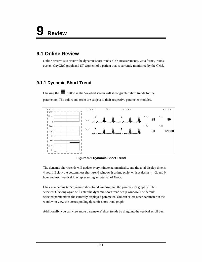
9-1
9 Review
9.1 Online Review Online review is to review the dynamic short trends, C.O. measurements, waveforms, trends, events, OxyCRG graph and ST segment of a patient that is currently monitored by the CMS.
9.1.1 Dynamic Short Trend
Clicking the button in the Viewbed screen will show graphic short trends for the
parameters. The colors and order are subject to their respective parameter modules. ×××× ××××××××××
××
98
××
60
××
80
××
120/80
××
××
××××
0-2-4h0
100
0
200
0
100
××
××
××
Figure 9-1 Dynamic Short Trend The dynamic short trends will update every minute automatically, and the total display time is 4 hours. Below the bottommost short trend window is a time scale, with scales in -4, -2, and 0 hour and each vertical line representing an interval of 1hour. Click in a parameter’s dynamic short trend window, and the parameter’s graph will be selected. Clicking again will enter the dynamic short trend setup window. The default selected parameter is the currently displayed parameter. You can select other parameter in the window to view the corresponding dynamic short trend graph. Additionally, you can view more parameters’ short trends by dragging the vertical scroll bar.
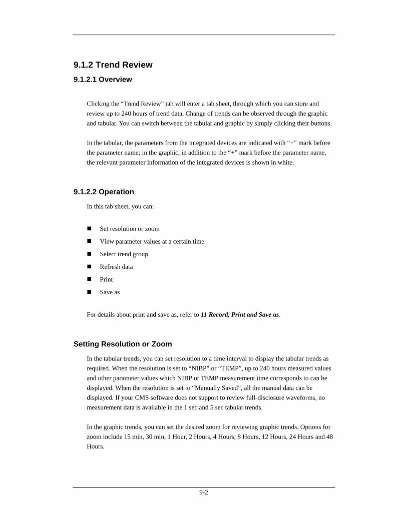
9-2
9.1.2 Trend Review 9.1.2.1 Overview
Clicking the “Trend Review” tab will enter a tab sheet, through which you can store and review up to 240 hours of trend data. Change of trends can be observed through the graphic and tabular. You can switch between the tabular and graphic by simply clicking their buttons. In the tabular, the parameters from the integrated devices are indicated with “+” mark before the parameter name; in the graphic, in addition to the “+” mark before the parameter name, the relevant parameter information of the integrated devices is shown in white,
9.1.2.2 Operation
In this tab sheet, you can:
Set resolution or zoom
View parameter values at a certain time
Select trend group
Refresh data
Save as
For details about print and save as, refer to 11 Record, Print and Save as.
Setting Resolution or Zoom
In the tabular trends, you can set resolution to a time interval to display the tabular trends as required. When the resolution is set to “NIBP” or “TEMP”, up to 240 hours measured values and other parameter values which NIBP or TEMP measurement time corresponds to can be displayed. When the resolution is set to “Manually Saved”, all the manual data can be displayed. If your CMS software does not support to review full-disclosure waveforms, no measurement data is available in the 1 sec and 5 sec tabular trends. In the graphic trends, you can set the desired zoom for reviewing graphic trends. Options for zoom include 15 min, 30 min, 1 Hour, 2 Hours, 4 Hours, 8 Hours, 12 Hours, 24 Hours and 48 Hours.
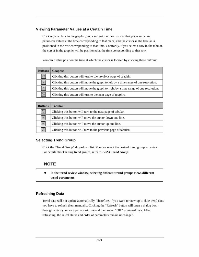
9-3
Viewing Parameter Values at a Certain Time
Clicking at a place in the graphic, you can position the cursor at that place and view parameter values at the time corresponding to that place, and the cursor in the tabular is positioned in the row corresponding to that time. Contrarily, if you select a row in the tabular, the cursor in the graphic will be positioned at the time corresponding to that row. You can further position the time at which the cursor is located by clicking these buttons:
Buttons Graphic
Clicking this button will turn to the previous page of graphic.
Clicking this button will move the graph to left by a time range of one resolution.
Clicking this button will move the graph to right by a time range of one resolution.
Clicking this button will turn to the next page of graphic.
Buttons Tabular
Clicking this button will turn to the next page of tabular.
Clicking this button will move the cursor down one line.
Clicking this button will move the cursor up one line.
Clicking this button will turn to the previous page of tabular.
Selecting Trend Group
Click the “Trend Group” drop-down list. You can select the desired trend group to review. For details about setting trend groups, refer to 12.2.4 Trend Group.
NOTE
In the trend review window, selecting different trend groups views different trend parameters.
Refreshing Data
Trend data will not update automatically. Therefore, if you want to view up-to-date trend data, you have to refresh them manually. Clicking the “Refresh” button will open a dialog box, through which you can input a start time and then select “OK” to re-read data. After refreshing, the select status and order of parameters remain unchanged.
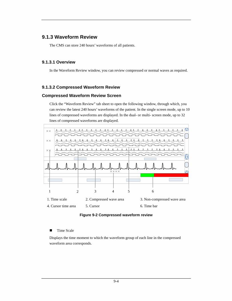
9-4
9.1.3 Waveform Review The CMS can store 240 hours’ waveforms of all patients.
9.1.3.1 Overview
In the Waveform Review window, you can review compressed or normal waves as required.
9.1.3.2 Compressed Waveform Review
Compressed Waveform Review Screen
Click the “Waveform Review” tab sheet to open the following window, through which, you can review the latest 240 hours’ waveforms of the patient. In the single screen mode, up to 10 lines of compressed waveforms are displayed. In the dual- or multi- screen mode, up to 32 lines of compressed waveforms are displayed.
××
××
××
××××
1. Time scale 2. Compressed wave area 3. Non-compressed wave area
4. Cursor time area 5. Cursor 6. Time bar
Figure 9-2 Compressed waveform review
Time Scale
Displays the time moment to which the waveform group of each line in the compressed waveform area corresponds.
1 2 63 4 5
9-5
Compressed Waveform Area
Displays compressed waveforms. If some waveform’s signal is not detected within a specific time period, square waves is displayed.
Non-compressed Wave Area
Displays compressed waveforms where the cursor is located with normal wave size, or displays the patient’s parameter information.
Cursor time area
Displays the time where the cursor is located.
Cursor
By moving the cursor, you can select six seconds, a total of 12 seconds of compressed waveforms before and after the central cursor point.
Time Bar
Same functions with that in the normal waveform review. Refer to 9.1.3.3 Normal Waveform Review-Normal Waveform Review Window.
Compressed Waveform Operation
In the compressed waveform review window, you can:
Select waveforms to be saved
Select waveforms
Mark arrhythmia
View arrhythmia statistic
Refresh
Show/hide parameter
Zoom
ICP waveform scale
Save as
For details about print and save as, refer to 11 Record, Print and Save as.
9-6
Selecting waveforms to be saved
By clicking the “Wave Save” button, you can select waveforms to be saved for each patient as desired following this procedure:
1. Select a patient from “Patient Info” list.
2. Select waveforms to be saved for this patient from the “Waveform” list.
3. Repeat Step 1 and Step 2 to select waveforms to be saved for other patients.
4. Select “OK” and the system will save all the selected waveforms.
The CMS can save up to 240 hours’ waveforms of all patients. If you did not select waveforms for a patient, no waveforms and parameter values can be reviewed from the “Waveform Review” window. For details about automatic waveform storage, refer to 5.1.3 Auto Waveform Storage.
Selecting Waveforms
Click the “Wave Select” button to pop up the menu of waveforms for your selection. Tick the checkbox before the desired wave (at most four waves) and the compressed waveform area will display the selected waves. Select a waveform by clicking on its name and change its order by clicking “Move First”, “Move Up”, “Move Down” or “Move Last”. Click “Save as Default” to save the current configuration as user’s default configuration; click “Load Configuration” to load the user’s default configuration on current patient.
NOTE
The waveform selection of new admitted patient is the user’s default configuration.
Marking Arrhythmia
You can mark any alarmed arrhythmia waveform with color in compressed waveform area. From the “ARR Mark” drop-down list, you can select the types of arrhythmia to be marked. Please refer to 12.2.1 Setting Color for how to set desired color for each type of arrhythmia.
9-7
NOTE
If multiple arrhythmia alarms occur at the same time, only the alarm(s) of highest level will be marked; if the arrhythmia alarms are of the same level, the alarm of highest priority will be marked.
Viewing Arrhythmia Statistic
Click the “ARR Statistic” button and in the pop-up menu you can view the statistic about the HR value and the number of each arrhythmia type during a certain time range. You can set the time range as 24 hours, 12 hours, or 8 hours. For details about print, refer to 11 Record, Print and Save as.
Showing/hiding Parameter
Click the “Numerics Data” or “Hide Numerics” button, the non-compressed waveform area will respectively display the patient’s parameter information or compressed waveforms where the cursor is located with normal wave width.
Zoom
Set the time span of each line in the compressed waveform window. The options are 15s, 30s, 45s, 1min and 2min. The longer the time span of each line sets, the more the lines of compressed waveform display on the screen. In single-screen mode, up to 10 lines of waves can be displayed; in dual- or multi- screen mode, up to 32 lines of waves can be displayed.
ICP Waveform Scale
When ICP is displayed in compressed waveform area, you can right click the mouse to adjust ICP waveform amplitude. Each time the right key you click, the scale is adjusted in the preset order. There are four levels of the scale: 0-15 mmHg, 0-20 mmHg, 0-30 mmHg and 0-40 mmHg. After change, the scale level displays above the ICP waveform.
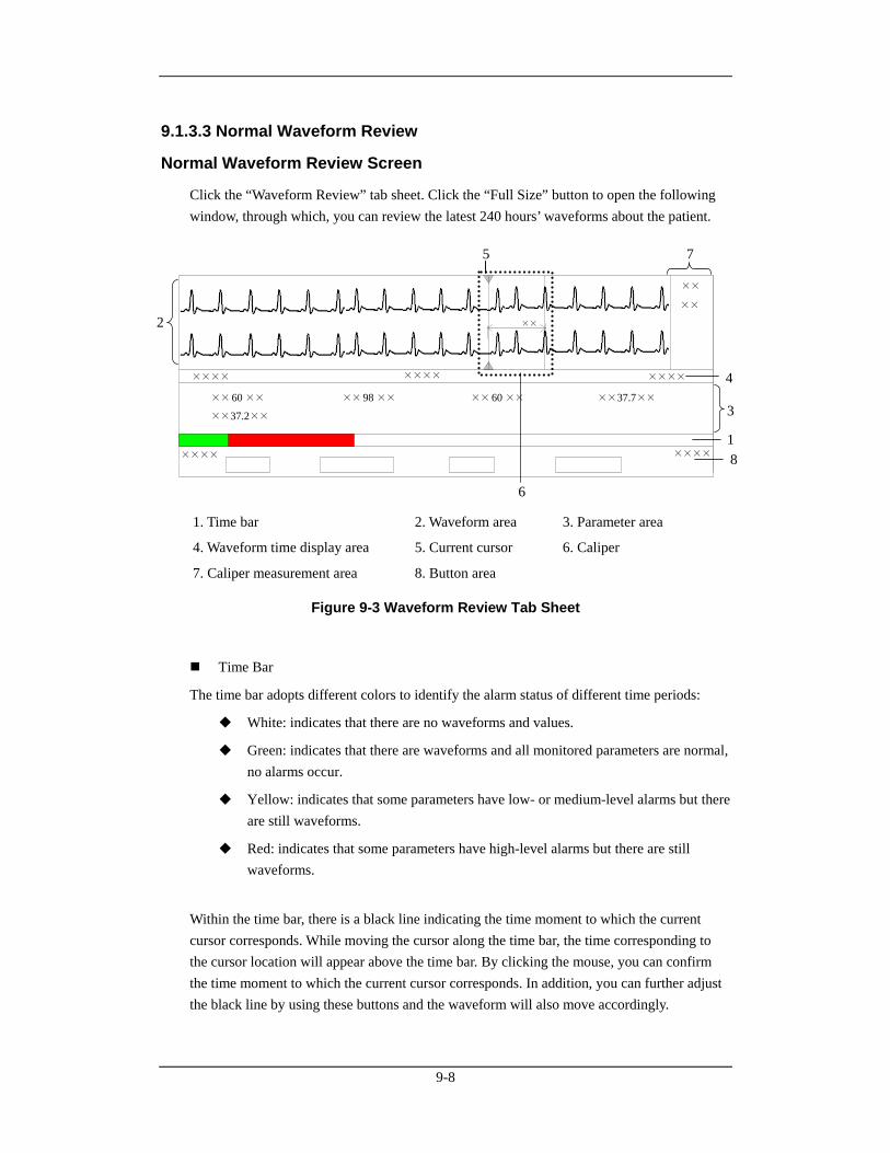
9-8
9.1.3.3 Normal Waveform Review
Normal Waveform Review Screen
Click the “Waveform Review” tab sheet. Click the “Full Size” button to open the following window, through which, you can review the latest 240 hours’ waveforms about the patient.
××××
×× 60 ×× ××98 ×× ×× 60 ×× ××37.7××
××37.2××
×××× ××××
××
×××× ××××
××
××
1. Time bar 2. Waveform area 3. Parameter area
4. Waveform time display area 5. Current cursor 6. Caliper
7. Caliper measurement area 8. Button area
Figure 9-3 Waveform Review Tab Sheet
Time Bar
The time bar adopts different colors to identify the alarm status of different time periods:
White: indicates that there are no waveforms and values.
Green: indicates that there are waveforms and all monitored parameters are normal, no alarms occur.
Yellow: indicates that some parameters have low- or medium-level alarms but there are still waveforms.
Red: indicates that some parameters have high-level alarms but there are still waveforms.
Within the time bar, there is a black line indicating the time moment to which the current cursor corresponds. While moving the cursor along the time bar, the time corresponding to the cursor location will appear above the time bar. By clicking the mouse, you can confirm the time moment to which the current cursor corresponds. In addition, you can further adjust the black line by using these buttons and the waveform will also move accordingly.
1
4
3
2
6
7 5
8
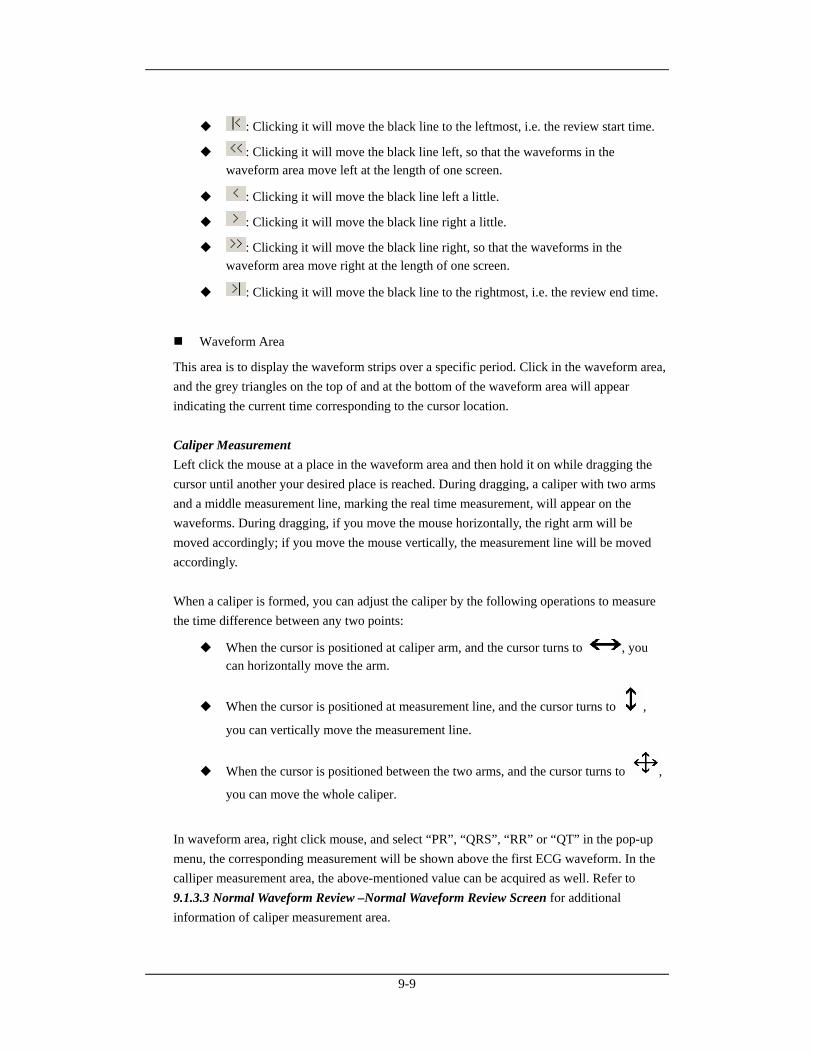
9-9
: Clicking it will move the black line to the leftmost, i.e. the review start time.
: Clicking it will move the black line left, so that the waveforms in the waveform area move left at the length of one screen.
: Clicking it will move the black line left a little.
: Clicking it will move the black line right a little.
: Clicking it will move the black line right, so that the waveforms in the waveform area move right at the length of one screen.
: Clicking it will move the black line to the rightmost, i.e. the review end time.
Waveform Area
This area is to display the waveform strips over a specific period. Click in the waveform area, and the grey triangles on the top of and at the bottom of the waveform area will appear indicating the current time corresponding to the cursor location. Caliper Measurement Left click the mouse at a place in the waveform area and then hold it on while dragging the cursor until another your desired place is reached. During dragging, a caliper with two arms and a middle measurement line, marking the real time measurement, will appear on the waveforms. During dragging, if you move the mouse horizontally, the right arm will be moved accordingly; if you move the mouse vertically, the measurement line will be moved accordingly. When a caliper is formed, you can adjust the caliper by the following operations to measure the time difference between any two points:
When the cursor is positioned at caliper arm, and the cursor turns to , you can horizontally move the arm.
When the cursor is positioned at measurement line, and the cursor turns to ,
you can vertically move the measurement line.
When the cursor is positioned between the two arms, and the cursor turns to ,
you can move the whole caliper.
In waveform area, right click mouse, and select “PR”, “QRS”, “RR” or “QT” in the pop-up menu, the corresponding measurement will be shown above the first ECG waveform. In the calliper measurement area, the above-mentioned value can be acquired as well. Refer to 9.1.3.3 Normal Waveform Review –Normal Waveform Review Screen for additional information of caliper measurement area.
9-10
NOTE
The current caliper measurements can be manually saved as an event.
The waveform review does not include caliper measurements.
ECG Waveform Gain You can set the ECG waveform gain in the waveform area by either way:
When the cursor is positioned at any ECG waveform, the buttons and
will display at the left end of the waveform. Click button can increase the
gain, and click button can decrease the gain.
Right click mouse, and select “Zoom in ECG Gain” or “Zoom out ECG Gain” in the pop-up menu.
Sweep Speed You can set the sweep speed by either way:
In waveform area, right click mouse, and select “Zoom in Sweep Speed” and “Zoom out Sweep Speed” to adjust the speed.
In button area, click “Sweep Speed” to set the waveform sweep speed. Refer to 9.1.3.3 Normal Waveform Review –Normal Waveform Review Screen for additional information of selecting sweep speed.
Caliper Measurement Area
The caliper measurement area is hidden by default. If the check box before “Caliper” is ticked at the right bottom corner of the screen, this area will be shown; otherwise it will be hidden. There are five measurement buttons and one “Clear” button. When the caliper is operated in the waveform area, click “PR”, “QRS”, “RR”, “QT” buttons in caliper measurement area, the corresponding measurement will display;the QTC value is calculated after RR and QT value have been acquired. You can clear all the values by click “Clear” button.
9-11
Parameter Area
By default, the parameter area is hidden. Clicking the “Numerics Data” button will show the parameter area. If parameter area is displayed, clicking the “Hide Numerics” button will hide the parameter area. Parameter area shows all current parameter values. For parameters having high-level alarms, they are highlighted in red and “***” is shown in front of the parameter values; for parameters having medium level alarms, they are highlighted in yellow and “**” is shown in front of the parameter values for parameters having low level alarms, they are highlighted in yellow and “*” is shown in front of the parameter values; for parameters having message, they are shown with black as the background color, but no indication by “*” before parameter values; for the parameters from integrated devices, they are shown in white and indicated with “+” before the parameter name.
Waveform Time Display Area
In this area, waveform start time and end time are respectively shown at leftmost and rightmost; the current cursor time is shown in the middle. By clicking the “Refresh” button, you can update the end time to current system time and the start time changes accordingly.
Button Area
Refer to 9.1.3.3 Normal Waveform Review –Normal Waveform Operation for additional information of button function.
Normal Waveform Operation
In the normal waveform review window, you can:
Select waveforms to be saved
Select waveforms
Select Sweep Speed
Save Event
Auto play
Record
Save as
Export to EMR
For details about record, print and save as, refer to 11 Record, Print and Save as.
9-12
Selecting waveforms to be saved
By clicking the “Wave Save” button, you can select waveforms to be saved for each patient as desired following this procedure:
1. Select a patient from “Patient Info” list.
2. Select waveforms to be saved for this patient from the “Waveform” list.
3. Repeat Step 1 and Step 2 to select waveforms to be saved for other patients.
4. Select “OK” and the system will save all the selected waveforms.
The CMS can save up to 240 hours’ waveforms of all patients. If you did not select waveforms for a patient, no waveforms and parameter values can be reviewed from the “Waveform Review” window. For details about automatic waveform storage, refer to 5.1.3 Auto Waveform Storage.
Selecting Waveforms
Click the “Wave Select” button, and a list of available waveforms will be shown. By default, all waveforms are selected. You can deselect a waveform by ticking its check box. Besides, you can drag a waveform name to change its display order.
Selecting Sweep Speed
By clicking the “Sweep Speed” button, you can set the width of waveforms displayed in the waveform area. Available options are 6.25 mm/s, 12.5 mm/s, 25 mm/s and 50 mm/s. Changing sweep speed will affect the time length of the waveform area. At the 1280×1024 resolution, the sweep speed and time length correlate as follows:
Sweep Speed Time length (approximate)
6.25 mm/s 12.5 mm/s 25 mm/s 50 mm/s
52.0s 26.0s 13.0s 6.5s
Saving Event
Clicking the “Save Event” button will enter a dialog box. Select the waveforms can be saved and input necessary event description. Then, select “OK” to save the currently displayed waveform stripe. The saved event can be viewed in the “Event Review” screen.
Auto Play
By clicking “Auto Play” and then the stepping buttons, you can review waveforms in the auto mode.
9-13
Export to EMR
By clicking “Export to EMR” button, you can export 20-second waveform data after the start time of current waveform to other systems.
NOTE
When the item “Export Waveform Data” in “Service Setup” tab sheet from “Admin Setup” – “Other” – “Gateway Communication Setting” is enabled, the function of Export to EMR can be used.
9.1.4 C.O. Review 9.1.4.1 Overview
Clicking the “C.O. Review” tab will enter a tab sheet, through which you can view up to 720 C.O. measurement curves and parameter values of a patient Below the C.O. review windows are the average C.O. and C.I. If you switch to the “Hemo Calcs” tab sheet from a C.O. review window, the system will take the average C.O. and C.I. corresponding to that C.O. review window as the inputs of hemodynamics calculation.
9.1.4.2 Operation
In the C.O. review window, you can:
Select measurements
Delete a set of measurements
Record
Save as
For details about record, print and save as, refer to 11 Record, Print and Save as.
Selecting Measure Results
The time corresponding to each measurement is listed in the “Measure results list”, from which you can select up to 6 measurements. To the right of the “Measure results list”, there are 6 C.O. review windows, displaying the C.O. curves and parameter values measured at 6 different times. Click in a C.O. review window. The border of the window will highlight in blue when it is selected.

9-14
Deleting a Set of Measurements
1. Select the time or C.O. review window corresponding to the measurement you want to delete.
2. Click the “Delete” button, and a dialog box for you to confirm the deletion will pop up.
3. Select “Yes” to delete the measurement.
9.1.5 Event Review 9.1.5.1 Overview
Clicking the “Event Review” tab will enter the following tab sheet, through which you can view all event parameters and waveforms of a patient.
1 Event list 2 Event parameter area 3 Event waveform area
Figure 9-4 Event Review Tab Sheet
1. Event list: displays event status (locked or not), time, message, priority, and description.
2. Event parameter area: displays all parameter values for each event time. The parameters from integrated devices are indicated with “+”before the parameter name, and the relevant text is shown in white. The CMS prompts if an alarm occurs to a specific parameter and indicates the alarm priority by using different background colors.
Black: no alarm generated;
Red: high level alarm generated;
Yellow: medium or low level alarm generated.
3. Event waveform area: displays relevant parameters’ waveforms within ±16 seconds around the event time. Please refer to 9.1.3.3 Normal Waveform Review –Normal Waveform Review Screen –Waveform Area for how to use caliper, how to adjust ECG waveform gain and how to adjust sweep speed in waveform area.
Select an event from the event list, and you will view its corresponding parameter values and waveforms in the event parameter area and event waveform area.
1
3
2
9-15
NOTE
For the event from integrated devices, there is no corresponding waveform in the event waveform area.
9.1.5.2 Operation
In the “Event Review” window, you can:
Select event type and alarm priority
Sequence the event list
Make selection
Lock and unlock
Delete
Sweep speed
Record
Save as
Export to EMR
For details about sweep speed, refer to 9.1.3.3 Normal Waveform Review –Normal Waveform Operation. For details about record, print and save as, refer to 11 Record, Print and Save as.
Selecting Event Type and Alarm Priority
Above the event list, there are two drop-down list boxes: “Filter by Event” and “Filter by Priority”. By clicking the down arrow buttons next to them, you can select event type and level. The selected events will be listed in the event list. Options for event type are “All”, “ECG”, “SpO2”, “RESP”, “NIBP”, “IBP”, “C.O.”, “TEMP” “CO2”, “GAS”, “ICG”, “BIS”, “RM”, “CCO”, “SvO2”, “ScvO2”, “Arr”, “ST Analysis”, “Saved Events”, “Anesthesia”, “Ventilator” ,“Unknown Phys. Alarm”, “User Initiated”(only for defibrillator), “Event” (only for telemetry monitor), and options for alarm priority include “All”, “High”, “Med” or “Low” or “Message”. By default, “All” for alarm type and “All” for alarm priority are selected.
9-16
Sequencing the Event List
You can sequence all alarms ascendingly or descendingly by clicking the heading of any column:
Time: Clicking it will sequence all alarms ascendingly or descendingly by time.
Message: Clicking it will sequence all alarms ascendingly or descendingly by parameter.
Description: Clicking it will sequence all alarms ascendingly or descendingly by description.
Priority: Clicking it will sequence all alarms ascendingly or descendingly by level.
At the same time, one of the following symbols will appear to the left of the heading:
for ascending sequence, and
for descending sequence.
By default, all events are sequenced descendingly by time.
Making Selection
You can select single, multiple or all events in event list:
Select one event: Click one event you wish to select.
Select multiple events: You can select more than one event with Ctrl or Shift keys.
Select the first event and then press and hold the Ctrl key. While holding down the Ctrl key, select each of the other events you wish to select. This will select multiple events that are not grouped together
Select the first event and then press and hold the Shift key. While holding the key down, click the last event. This will select all the events in-between the first and last event.
Select all events: Click any event in the list, and then press Ctrl and A keys down together and then all the events in the event list will be selected.
9-17
Locking and Unlocking Event
Select an event from the event list and then click the “Lock” button. The icon will appear to its left when the event is locked. The locked event cannot be deleted automatically, but can be deleted manually. When a locked event is selected, the button “Lock” will change to “Unlock”. You can click the “Unlock” button to unlock the locked event.
NOTE
If events are all locked, the CMS will subsequently delete the oldest locked event with each addition of a new event when system storage reaches capacity automatically.
Deleting Event
1. Select the event you wish to delete from the event list.
2. Click the “Delete” button.
3. Select “OK” from the pop-up dialog box. This event will be deleted.
Export to EMR
Select one event from event list, and then click “Export to EMR” button. The event related data can be exported to other systems.
NOTE
When the item “Export Waveform Data” in “Service Setup” tab sheet from “Admin Setup” – “Other” – “Gateway Communication Setting” is enabled, the function of Export to EMR can be used.
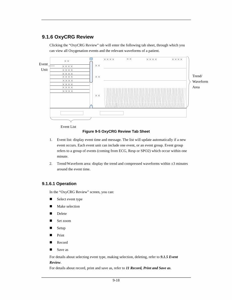
9-18
9.1.6 OxyCRG Review Clicking the “OxyCRG Review” tab will enter the following tab sheet, through which you can view all Oxygenation events and the relevant waveforms of a patient.
××××××××××××
××××
××××
××××
××××
××××
××××
××××
××××
××××××
××
××
Figure 9-5 OxyCRG Review Tab Sheet
1. Event list: display event time and message. The list will update automatically if a new event occurs. Each event unit can include one event, or an event group. Event group refers to a group of events (coming from ECG, Resp or SPO2) which occur within one minute.
2. Trend/Waveform area: display the trend and compressed waveforms within ±3 minutes around the event time.
9.1.6.1 Operation
In the “OxyCRG Review” screen, you can:
Select event type
Make selection
Delete
Set zoom
Setup
Record
Save as
For details about selecting event type, making selection, deleting, refer to 9.1.5 Event Review. For details about record, print and save as, refer to 11 Record, Print and Save as.
Event List
Trend/ Waveform Area
Event Unit
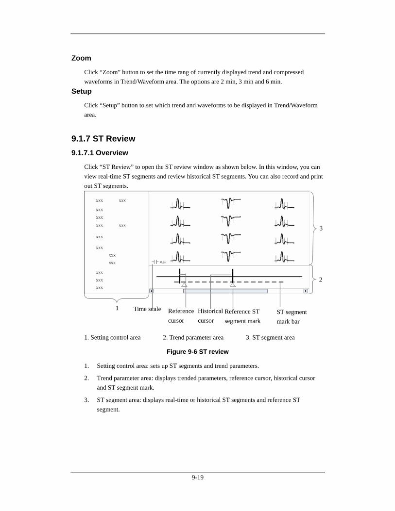
9-19
Zoom
Click “Zoom” button to set the time rang of currently displayed trend and compressed waveforms in Trend/Waveform area. The options are 2 min, 3 min and 6 min.
Setup
Click “Setup” button to set which trend and waveforms to be displayed in Trend/Waveform area.
9.1.7 ST Review 9.1.7.1 Overview
Click “ST Review” to open the ST review window as shown below. In this window, you can view real-time ST segments and review historical ST segments. You can also record and print out ST segments.
1. Setting control area 2. Trend parameter area 3. ST segment area
Figure 9-6 ST review
1. Setting control area: sets up ST segments and trend parameters.
2. Trend parameter area: displays trended parameters, reference cursor, historical cursor and ST segment mark.
3. ST segment area: displays real-time or historical ST segments and reference ST segment.
1
3
2
Reference cursor
Reference ST segment mark
ST segment mark bar
Time scale Historical cursor
9-20
9.1.7.2 Operation
In the ST review window, you can:
View ST segment
Set reference ST segment
Select reference ST segment
Delete reference ST segment
Set waveform speed
Set trend parameter
Record
For details about record and print, refer to 11 Record, Print and Save as.
Viewing ST Segment
In the setting control area, you can select “Realtime” to view real-time ST segments, “Historical” to view historical ST segments by using the “View Hist.” buttons. You can also view historical ST segments by clicking any position in the parameter trend area.
Setting Reference ST Segment
When viewing real-time ST segments, click “Set as Ref.” to set the real-time ST segment to reference ST segment. When viewing historical ST segments, click “Set as Ref.” to set the ST segment located at the historical cursor to the reference ST segment.
Selecting Reference ST Segment
You can click the “Change Ref.” buttons to set the reference ST segment located at the reference cursor to the current reference ST segment.
Deleting Reference ST Segment
You can click the “Delete Ref.” button to delete the reference ST segment located at the reference cursor.
Setting Waveform Speed
You can click the “Sweep Speed” drop-down list to set different waveform speeds. The time scale in the ST segment area is related to the waveform speed set. The greater the waveform speed, the smaller the time scale.
9-21
Setting Trend Parameter
You can click the “Trend Parameter” drop-down list to select two different trend parameters and “Zoom” drop-down list to set different time lengths. The parameter trend data is not refreshed automatically. You can click the “Refresh” button and set start time in the pop-up window, and then click “OK” to read the data again.
NOTE
There is no data displayed in the trend parameter area when viewing real-time ST segments.
9.2 Discharged Patients The CMS is capable of searching and reviewing the history data of up to 20,000 patients. It includes all patients, patient management, waveform review, trend review, event review, OxyCRG review, ST review and C.O. review. By clicking the “Discharged Pat.” tab, you can enter the tab sheet, which contains six tabs as follows:
All patients
Patient Mgmt.
Waveform Review
Trend Review
Event Review
OxyCRG Review
ST Review
C.O. Review
NOTE
The patient management, waveform review, trend review, event review, OxyCRG review, ST review and C.O. review for discharged patients are basically the same with that for online patients. For details, refer to 9.1 Online Review.
9-22
9.2.1 All Patients 9.2.1.1 Overview
In the “All patients” tab sheet, you can view discharged patients’ data of all CMSs on the network. Brief information of discharged patients on the selected CMS is shown in the patient list, with each line for one discharged patient.
NOTE
The discharged patients on a CMS can be viewed only when the IP address of a CMS is added in the “System Setup” menu. Please refer to 12.2.8 Other - Multi-CMS Communication Settings for adding an IP address.
9.2.1.2 Operation
In the “All patients” tab sheet, you can:
Sequence discharged patient
Change column order
Search discharged patient
Delete discharged patient
Refresh
Sequencing Discharged Patient
You can sequence all discharged patients ascendingly or descendingly by clicking the heading of any column. At the same time, one of the following symbols will appear to the left of the heading:
for ascending sequence, and
for descending sequence.
By default, all discharged patients are sequenced ascendingly by name.
Searching Discharged Patient
1. Click the button at the left of the “All patients” tab sheet, and the “All patients” tab sheet will show an area for inputting search conditions at its left.
2. Input search conditions, e.g. “Name” and “Patient ID”. You can click the “More Options” to input more search conditions.
3. Click the “Search” button. The system will search and display the discharged patients that meet the search conditions.
9-23
Deleting Discharged Patient
1. In the “Delete or not” column, select the check box corresponding to the patient that you want to delete.
2. Click the “Delete” button.
3. Select “Yes” from the pop-up dialog box.
Refreshing Data
Clicking the “Refresh” button will update the discharged patient list.
NOTE
Only after selecting a discharged patient from the “All patients” tab sheet, you can switch to other tab sheets for review.
If a patient is allowed to be viewed by remote CMS during monitoring, his physiological data can be viewed in the “Discharged Pat.” window of other CMSs after he is discharged.

9-24
FOR YOUR NOTES

10-1
10 Calculation
NOTE
If the version of currently used CMS system software is lower than 3.0, some of calculation results will be deleted or refreshed due to the update of calculation formula.
10.1 Drug Calculation Clicking the “Drug Calcs” tab will enter the tab sheet. The “Calculated Results List” shows the time corresponding to a maximum of 75 calculations. The drug parameter area is for you to enter parameter values and to display calculations. The titration table is to show titrated results. The button area contains the following buttons:
Calc.
Save Results
Delete
Record
Save As
For details about “Record”, “Print” and “Save as”, refer to 11 Record, Print and Save as.
10-2
Calculate
From the “Name” drop-down list below, you can select one to calculate its amount, liquid volume, concentration, etc.
Drug A
Drug B
Drug C
Drug D
Drug E
AMINOPHYLLINE
DOBUTAMINE
DOPAMINE
EPINEPHRINE
HEPARIN
ISUPREL
LIDOCAINE
NIPRIDE
NITROGLYCERIN
PITOCIN
NOTE
Drug A through Drug E are user-defined drugs.
Procedure
1. Confirm whether the patient type is correct and the weight entered.
2. Select a drug to be calculated.
3. The system will give a set of values automatically. You cannot take them as the calculations. Instead, you should input correct parameter values under the direction of a doctor.
4. Select “Reference”, “Step” and “Dose Type” for titration table.
5. Click the “Calc.” button. The calculations will be displayed in the drug parameter area and titration table.
10-3
WARNING
Be sure to input correct parameter values. The user must verify the correctness of the calculations displayed on the screen before using them.
The calculations in the titration table are subject to the drug calculations, therefore, the correctness of the drug calculations must be ensured. Besides, the reference, step and dose type should be ensured correct.
We assume no responsibility for the results arising from incorrect inputs and operations.
Save Results
The CMS is capable of saving 75 calculations for each patient. To save calculations, you can click the “Save Results” button after calculation is finished. If the drug you select is a user-defined drug, the system will open the “Enter drug name” dialog box. Input a drug name and click “OK”. The system will remember this name and collect it into the Name drop-down list for later use. All the saved calculations and their respective calculate time are displayed in the “Calculated Results List”, from which you can select one to view its corresponding calculations in the drug parameter area. At this time, all parameters in the drug parameter area are unchangeable but the reference, step and dose type in the titration table can be changed, and the “Calc.” button converts to “New Calc.”. Clicking the “New Calc.” button, you can input new parameter values for another calculation.
Delete
To delete the unnecessary or wrong calculations, follow this procedure:
1. Select the time corresponding to the calculation you want to delete from the “Calculated Results List”.
2. Click the “Delete” button below the “Calculated Results List”.
3. Select “Yes” in the message box. The calculation will be deleted.
10-4
10.2 Hemodynamics Calculation Clicking the “Hemo Calcs” tab will enter the tab sheet. The “Calculated Results List” shows the time corresponding to a maximum of 100 calculations. The “Input Item” area allows you to enter parameter values and the “Calculated Results” area is to display calculations. In this tab sheet, you can:
Calculate
Save results
Delete
Record
Save as.
For details about “Record”, “Print” and “Save as”, refer to 11 Record, Print and Save as.
Calculate
1. Input parameter values needed into the “Input Item” area.
2. Click the “Calc.” button. The calculations of other parameters will be displayed in the “Calculated Results” area. Values which are beyond the normal range will be displayed on a yellow background.
WARNING
Be sure to input correct parameter values. The user must verify the correctness of the calculations displayed on the screen before using them. We assume no responsibility for the results arising from incorrect inputs and operations.
10-5
Save Results
The CMS is capable of saving 100 calculations for each patient. To save calculations, you can click the “Save Results” button after calculation is finished.
NOTE
If you continue to perform the “Save Results” operation when the number of calculations exceeds 100, the system will delete the earliest calculation and its corresponding time from the “Calculated Results List” before saving the new one.
Delete
To delete unnecessary or wrong calculations, follow this procedure:
1. Select the time corresponding to the calculation you want to delete from the “Calculated Results List”.
2. Click the “Delete” button below the “Calculated Results List”.
3. Select “Yes” in the message box. The calculation will be deleted.
10.3 Oxygenation Calculation Clicking the “Oxygenation Calc.” tab will enter the tab sheet. The “Calculated Results List” shows the time corresponding to a maximum of 100 calculations. The “Input Item” area allows you to enter parameter values and the “Calculated Results” area is to display calculations. In this tab sheet, you can:
Calculate
Save results
Delete
Record
Save as.
For details about “Record”, “Print” and “Save as”, refer to 11 Record, Print and Save as.
10-6
Calculate
1. Input parameter values needed into the “Input Item” area.
2. Pressure unit, Hb unit and Oxygen content unit can be changed by scrolling the pull-down lists at the right side of “Press Unit” or “OxyCont Unit”. Parameter values will automatically change and refresh accordingly.
3. Click the “Calc.” button. The calculations of other parameters will be displayed in the “Calculated Results” area. Parameter values which are beyond the normal range will be displayed on a yellow background.
WARNING
Be sure to input correct parameter values. The user must verify the correctness of the calculations displayed on the screen before using them. We assume no responsibility for the results arising from incorrect inputs and operations.
Save Results
The CMS is capable of saving 100 calculations for each patient. To save calculations, you can click the “Save Results” button after calculation is finished.
NOTE
If you continue to perform the “Save Results” operation when the number of calculations exceeds 100, the system will delete the earliest calculation and its corresponding time from the “Calculated Results List” before saving the new one.
Delete
To delete unnecessary or wrong calculations, follow the procedure:
1. Select the time corresponding to the calculation you want to delete from the “Calculated Results List”.
2. Click the “Delete” button below the “Calculated Results List”.
3. Select “Yes” in the message box. The calculation will be deleted.
10-7
10.4 Ventilation Calculation Clicking the “Ventilation Calc.” tab will enter the tab sheet. The “Calculated Results List” shows the time corresponding to a maximum of 100 calculations. The “Input Item” area allows you to enter parameter values and the “Calculated Results” area is to display calculations. In this tab sheet, you can:
Calculate
Save results
Delete
Record
Save as.
For details about “Record”, “Print” and “Save as”, refer to 11 Record, Print and Save as.
Calculate
1. Input parameter values needed into the “Input Item” area.
2. Pressure unit can be changed by scrolling the pull-down list at the right side of “Press Unit”. Pressure values will automatically change and refresh accordingly.
3. Click the “Calc” button. The calculations of other parameters will be displayed in the “Calculated Results” area. Parameter values which are beyond the normal range will be displayed on a yellow background.
WARNING
Be sure to input correct parameter values. The user must verify the correctness of the calculations displayed on the screen before using them. We assume no responsibility for the results arising from incorrect inputs and operations.
Save Results
The CMS is capable of saving 100 calculations for each patient. To save calculations, you can click the “Save Results” button after calculation is finished.

10-8
NOTE
If you continue to perform the “Save Results” operation when the number of calculations exceeds 100, the system will delete the earliest calculation and its corresponding time from the “Calculated Results List” before saving the new one.
Delete
To delete unnecessary or wrong calculations, follow the procedure:
1. Select the time corresponding to the calculation you want to delete from the “Calculated Results List”.
2. Click the “Delete” button below the “Calculated Results List”.
3. Select “Yes” in the message box. The calculation will be deleted.
10.5 Renal Calculation Clicking the “Renal Calc.” tab will enter the tab sheet. The “Calculated Results List” shows the time corresponding to a maximum of 100 calculations. The “Input Item” area allows you to enter parameter values and the “Calculated Results” area is to display calculations. In this tab sheet, you can:
Calculate
Save results
Delete
Record
Save as.
For details about “Record”, “Print” and “Save as”, refer to 11 Record, Print and Save as.
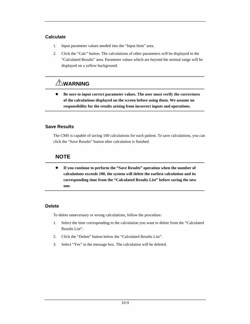
10-9
Calculate
1. Input parameter values needed into the “Input Item” area.
2. Click the “Calc” button. The calculations of other parameters will be displayed in the “Calculated Results” area. Parameter values which are beyond the normal range will be displayed on a yellow background.
WARNING
Be sure to input correct parameter values. The user must verify the correctness of the calculations displayed on the screen before using them. We assume no responsibility for the results arising from incorrect inputs and operations.
Save Results
The CMS is capable of saving 100 calculations for each patient. To save calculations, you can click the “Save Results” button after calculation is finished.
NOTE
If you continue to perform the “Save Results” operation when the number of calculations exceeds 100, the system will delete the earliest calculation and its corresponding time from the “Calculated Results List” before saving the new one.
Delete
To delete unnecessary or wrong calculations, follow the procedure:
1. Select the time corresponding to the calculation you want to delete from the “Calculated Results List”.
2. Click the “Delete” button below the “Calculated Results List”.
3. Select “Yes” in the message box. The calculation will be deleted.

10-10
FOR YOUR NOTES
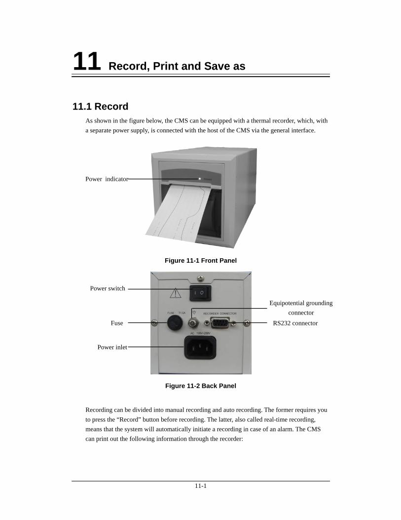
11-1
11 Record, Print and Save as
11.1 Record As shown in the figure below, the CMS can be equipped with a thermal recorder, which, with a separate power supply, is connected with the host of the CMS via the general interface.
Figure 11-1 Front Panel
Figure 11-2 Back Panel
Recording can be divided into manual recording and auto recording. The former requires you to press the “Record” button before recording. The latter, also called real-time recording, means that the system will automatically initiate a recording in case of an alarm. The CMS can print out the following information through the recorder:
Power indicator
Power switch
Fuse
Power inlet
RS232 connector
Equipotential grounding connector

11-2
Patient Information
Drug Calculations
Hemodynamics Calculations
Oxygenation Calculations
Ventilation Calculations
Renal Calculations
Waveforms
Events
C.O. Measurements
ST Review
ICG Hemodynamic Parameters
CCO Hemodynamic Parameters
SvO2/ScvO2 Oxygenation Parameters
OxyCRG Graph
OxyCRG Event
Real-time Waveforms
Real-time Frozen Waveforms
Real-time Alarms.
11.1.1 Installing Recorder Paper
WARNING
Be sure to use standard (50mm) thermal recorder paper only; otherwise, the recorder may show poor quality on record, or may be unusable, or the printer head of the recorder may be damaged.
Be careful to avoid damaging the printer head when installing recorder paper. Never pull open the paper bail at the upper left corner of the recorder except you prepare to replace the recorder paper or remove a trouble.
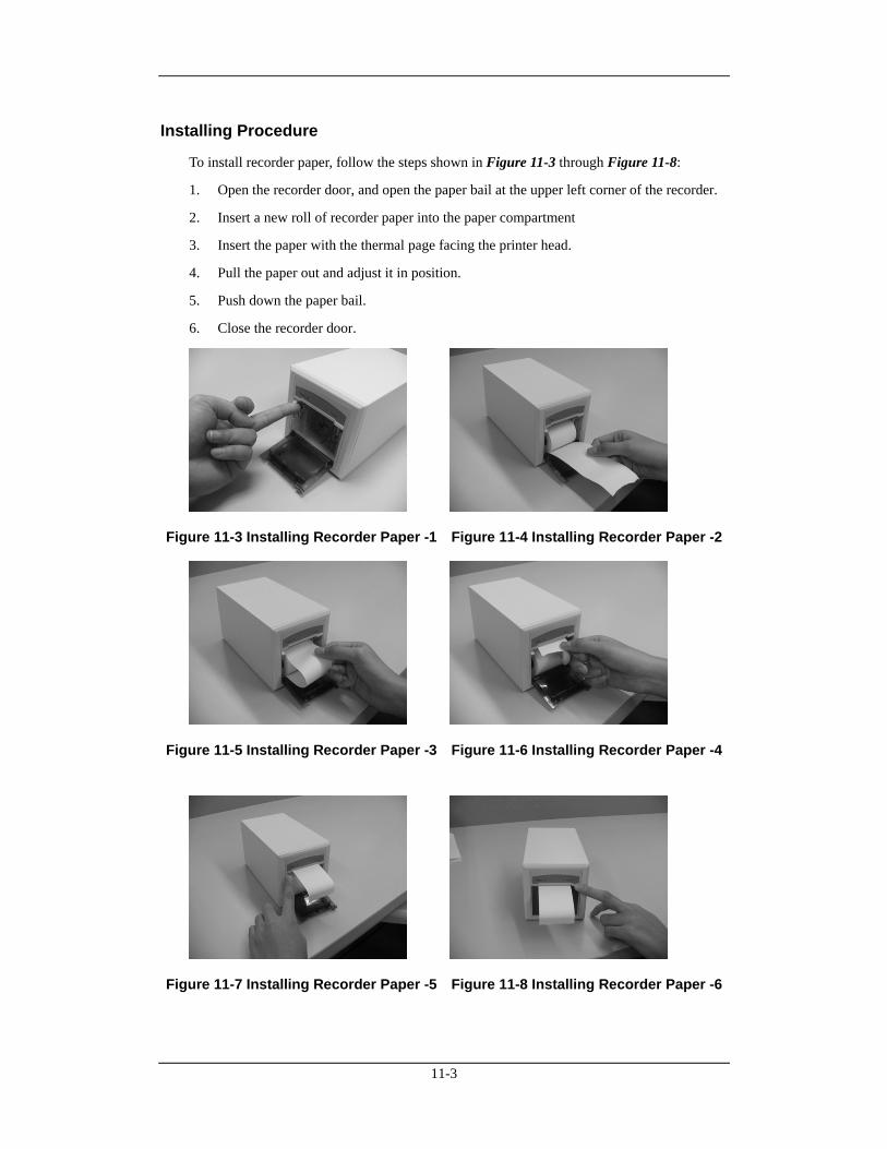
11-3
Installing Procedure
To install recorder paper, follow the steps shown in Figure 11-3 through Figure 11-8:
1. Open the recorder door, and open the paper bail at the upper left corner of the recorder.
2. Insert a new roll of recorder paper into the paper compartment
3. Insert the paper with the thermal page facing the printer head.
4. Pull the paper out and adjust it in position.
5. Push down the paper bail.
6. Close the recorder door.
Figure 11-3 Installing Recorder Paper -1 Figure 11-4 Installing Recorder Paper -2
Figure 11-5 Installing Recorder Paper -3 Figure 11-6 Installing Recorder Paper -4
Figure 11-7 Installing Recorder Paper -5 Figure 11-8 Installing Recorder Paper -6
11-4
11.1.2 Recorder Operations Recording Patient Information
1. Enter the “Patient Mgmt.” tab sheet.
2. Make sure that the patient information is correct.
3. Click the “Record” button to print out the patient information.
Recording Drug Calculations
1. Enter the “Drug Calcs” tab sheet.
2. Perform drug calculation as per part 10.1 Drug Calculation.
3. Click the “Record” button to print out the drug calculations result.
Recording Hemodynamics Calculations
1. Enter the “Hemo Calcs” tab sheet.
2. Perform hemodynamics calculation as per part 10.2 Hemodynamics Calculation.
3. Click the “Record” button to print out the hemodynamics calculations.
Recording Oxygenation Calculations
1. Enter the “Oxygenation Calc.” tab sheet.
2. Perform oxygenation calculation as per part 10.3 Oxygenation Calculation.
3. Click the “Record” button to print out the oxygenation calculations.
Recording Ventilation Calculations
1. Enter the “Ventilation Calc.” tab sheet.
2. Perform ventilation calculation as per part 10.4 Ventilation Calculation.
3. Click the “Record” button to print out the ventilation calculations.
Recording Renal Calculations
1. Enter the “Renal Calc.” tab sheet.
2. Perform renal calculation per part 10.5 Renal Calculation.
3. Click the “Record” button to print out the renal calculations.
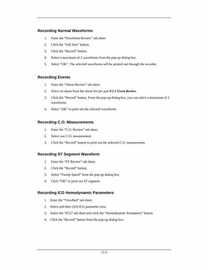
11-5
Recording Normal Waveforms
1. Enter the “Waveform Review” tab sheet.
2. Click the “Full Size” button.
3. Click the “Record” button.
4. Select a maximum of 2 waveforms from the pop-up dialog box.
5. Select “OK”. The selected waveforms will be printed out through the recorder.
Recording Events
1. Enter the “Alarm Review” tab sheet.
2. Select an alarm from the alarm list per part 9.1.5 Event Review.
3. Click the “Record” button. From the pop-up dialog box, you can select a maximum of 2 waveforms.
4. Select “OK” to print out the selected waveforms.
Recording C.O. Measurements
1. Enter the “C.O. Review” tab sheet.
2. Select one C.O. measurement.
3. Click the “Record” button to print out the selected C.O. measurement.
Recording ST Segment Waveform
1. Enter the “ST Review” tab sheet.
2. Click the “Record” button.
3. Select “Sweep Speed” from the pop-up dialog box.
4. Click “OK” to print out ST segment.
Recording ICG Hemodynamic Parameters
1. Enter the “ViewBed” tab sheet.
2. Select and then click ICG parameter area.
3. Select the “ICG” tab sheet and click the “Hemodynamic Parameters” button.
4. Click the “Record” button from the pop-up dialog box.
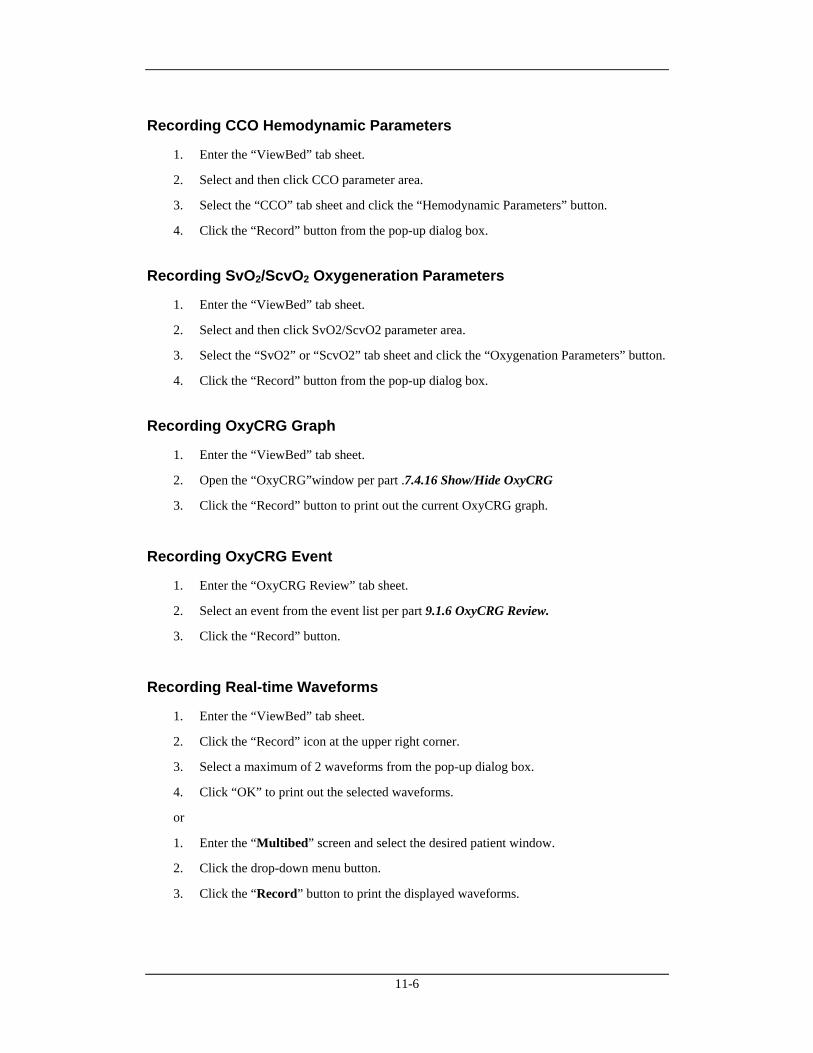
11-6
Recording CCO Hemodynamic Parameters
1. Enter the “ViewBed” tab sheet.
2. Select and then click CCO parameter area.
3. Select the “CCO” tab sheet and click the “Hemodynamic Parameters” button.
4. Click the “Record” button from the pop-up dialog box.
Recording SvO2/ScvO2 Oxygeneration Parameters
1. Enter the “ViewBed” tab sheet.
2. Select and then click SvO2/ScvO2 parameter area.
3. Select the “SvO2” or “ScvO2” tab sheet and click the “Oxygenation Parameters” button.
4. Click the “Record” button from the pop-up dialog box.
Recording OxyCRG Graph
1. Enter the “ViewBed” tab sheet.
2. Open the “OxyCRG”window per part .7.4.16 Show/Hide OxyCRG
3. Click the “Record” button to print out the current OxyCRG graph.
Recording OxyCRG Event
1. Enter the “OxyCRG Review” tab sheet.
2. Select an event from the event list per part 9.1.6 OxyCRG Review.
3. Click the “Record” button.
Recording Real-time Waveforms
1. Enter the “ViewBed” tab sheet.
2. Click the “Record” icon at the upper right corner.
3. Select a maximum of 2 waveforms from the pop-up dialog box.
4. Click “OK” to print out the selected waveforms.
or
1. Enter the “Multibed” screen and select the desired patient window.
2. Click the drop-down menu button.
3. Click the “Record” button to print the displayed waveforms.
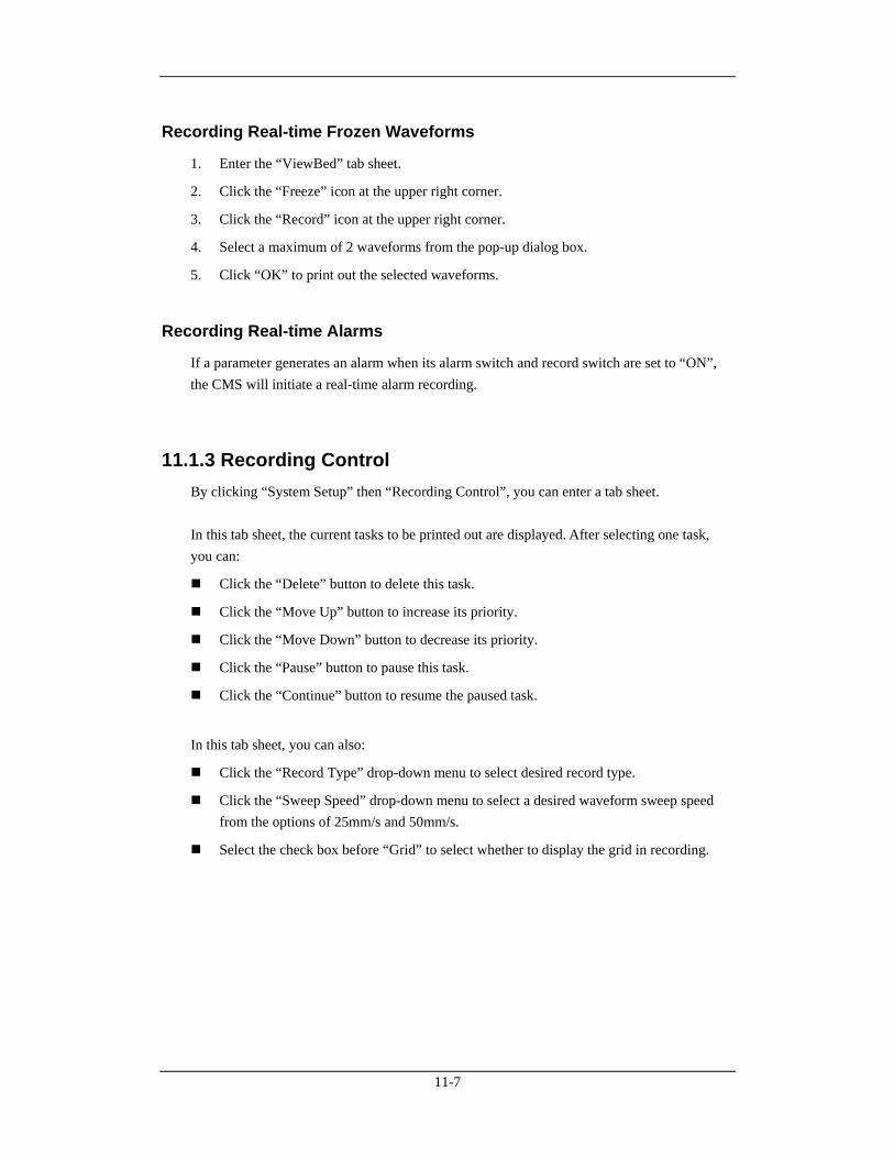
11-7
Recording Real-time Frozen Waveforms
1. Enter the “ViewBed” tab sheet.
2. Click the “Freeze” icon at the upper right corner.
3. Click the “Record” icon at the upper right corner.
4. Select a maximum of 2 waveforms from the pop-up dialog box.
5. Click “OK” to print out the selected waveforms.
Recording Real-time Alarms
If a parameter generates an alarm when its alarm switch and record switch are set to “ON”, the CMS will initiate a real-time alarm recording.
11.1.3 Recording Control By clicking “System Setup” then “Recording Control”, you can enter a tab sheet. In this tab sheet, the current tasks to be printed out are displayed. After selecting one task, you can:
Click the “Delete” button to delete this task.
Click the “Move Up” button to increase its priority.
Click the “Move Down” button to decrease its priority.
Click the “Pause” button to pause this task.
Click the “Continue” button to resume the paused task.
In this tab sheet, you can also:
Click the “Record Type” drop-down menu to select desired record type.
Click the “Sweep Speed” drop-down menu to select a desired waveform sweep speed from the options of 25mm/s and 50mm/s.
Select the check box before “Grid” to select whether to display the grid in recording.
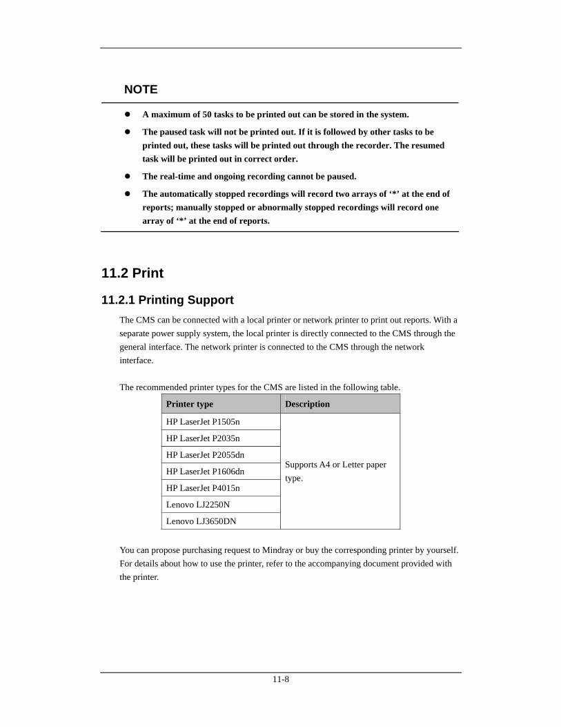
11-8
NOTE
A maximum of 50 tasks to be printed out can be stored in the system.
The paused task will not be printed out. If it is followed by other tasks to be printed out, these tasks will be printed out through the recorder. The resumed task will be printed out in correct order.
The real-time and ongoing recording cannot be paused.
The automatically stopped recordings will record two arrays of ‘*’ at the end of reports; manually stopped or abnormally stopped recordings will record one array of ‘*’ at the end of reports.
11.2 Print
11.2.1 Printing Support The CMS can be connected with a local printer or network printer to print out reports. With a separate power supply system, the local printer is directly connected to the CMS through the general interface. The network printer is connected to the CMS through the network interface. The recommended printer types for the CMS are listed in the following table.
Printer type Description
HP LaserJet P1505n
HP LaserJet P2035n
HP LaserJet P2055dn
HP LaserJet P1606dn
HP LaserJet P4015n
Lenovo LJ2250N
Lenovo LJ3650DN
Supports A4 or Letter paper type.
You can propose purchasing request to Mindray or buy the corresponding printer by yourself. For details about how to use the printer, refer to the accompanying document provided with the printer.
11-9
11.2.2 Printing Contents Through the printer, the CMS can print:
Patient information
Drug calculations
Hemodynamics calculations
Oxygenation calculations
Ventilation calculations
Renal calculations
Graphic or tabular
Waveforms
Arrhythmia statistic result
Events
C.O. measurements
ST segment waveform
Real-time report
12-lead ECG report
Multi-lead ECG report
EEG report
CSA report
ICG Hemodynamic Parameters
CCO Hemodynamic Parameters
SvO2/ScvO2 Oxygeneration Parameters
OxyCRG Graph
OxyCRG Event List
OxyCRG Event
Alarm Settings Report
Real-time Alarm Report
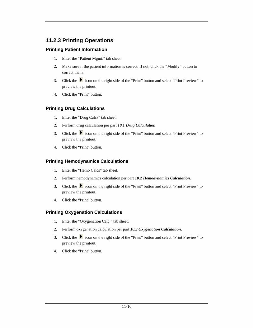
11-10
11.2.3 Printing Operations Printing Patient Information
1. Enter the “Patient Mgmt.” tab sheet.
2. Make sure if the patient information is correct. If not, click the “Modify” button to correct them.
3. Click the icon on the right side of the “Print” button and select “Print Preview” to preview the printout.
4. Click the “Print” button.
Printing Drug Calculations
1. Enter the “Drug Calcs” tab sheet.
2. Perform drug calculation per part 10.1 Drug Calculation.
3. Click the icon on the right side of the “Print” button and select “Print Preview” to preview the printout.
4. Click the “Print” button.
Printing Hemodynamics Calculations
1. Enter the “Hemo Calcs” tab sheet.
2. Perform hemodynamics calculation per part 10.2 Hemodynamics Calculation.
3. Click the icon on the right side of the “Print” button and select “Print Preview” to preview the printout.
4. Click the “Print” button.
Printing Oxygenation Calculations
1. Enter the “Oxygenation Calc.” tab sheet.
2. Perform oxygenation calculation per part 10.3 Oxygenation Calculation.
3. Click the icon on the right side of the “Print” button and select “Print Preview” to preview the printout.
4. Click the “Print” button.
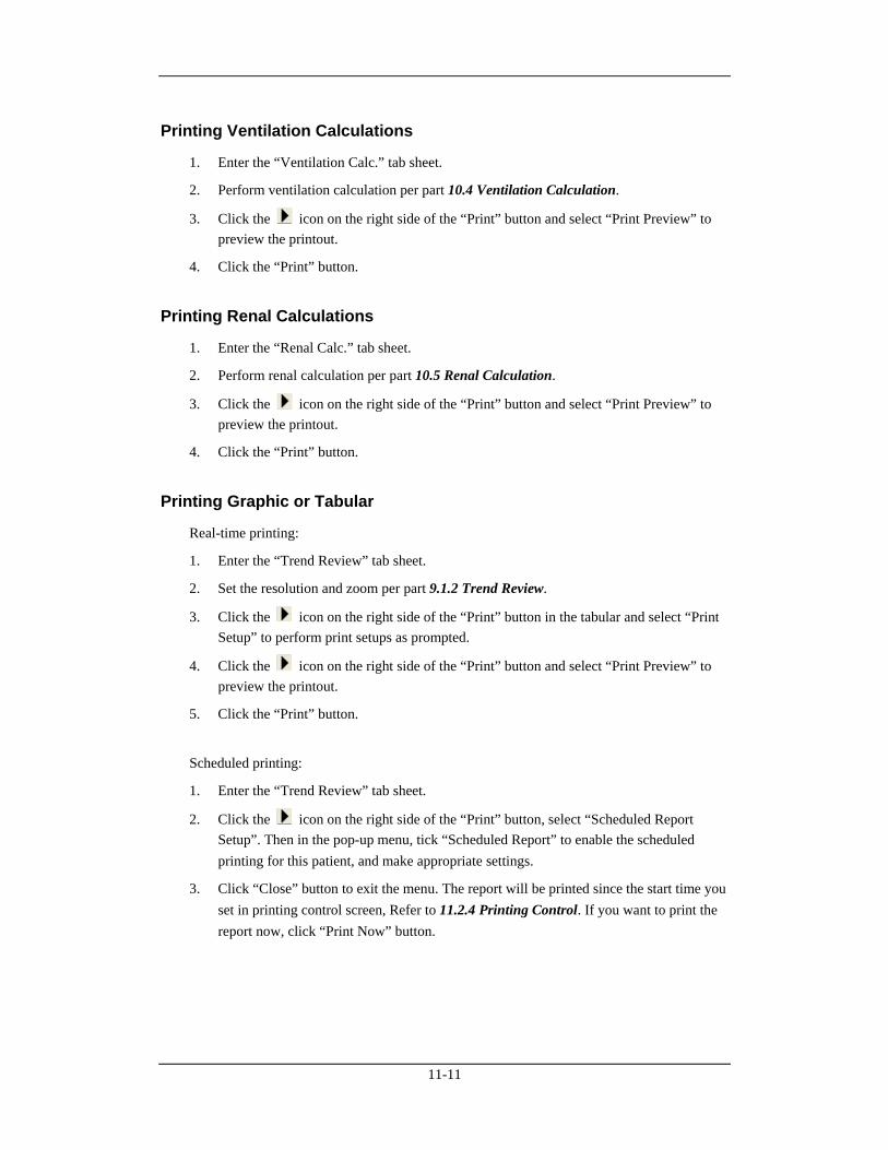
11-11
Printing Ventilation Calculations
1. Enter the “Ventilation Calc.” tab sheet.
2. Perform ventilation calculation per part 10.4 Ventilation Calculation.
3. Click the icon on the right side of the “Print” button and select “Print Preview” to preview the printout.
4. Click the “Print” button.
Printing Renal Calculations
1. Enter the “Renal Calc.” tab sheet.
2. Perform renal calculation per part 10.5 Renal Calculation.
3. Click the icon on the right side of the “Print” button and select “Print Preview” to preview the printout.
4. Click the “Print” button.
Printing Graphic or Tabular
Real-time printing:
1. Enter the “Trend Review” tab sheet.
2. Set the resolution and zoom per part 9.1.2 Trend Review.
3. Click the icon on the right side of the “Print” button in the tabular and select “Print Setup” to perform print setups as prompted.
4. Click the icon on the right side of the “Print” button and select “Print Preview” to preview the printout.
5. Click the “Print” button.
Scheduled printing:
1. Enter the “Trend Review” tab sheet.
2. Click the icon on the right side of the “Print” button, select “Scheduled Report Setup”. Then in the pop-up menu, tick “Scheduled Report” to enable the scheduled printing for this patient, and make appropriate settings.
3. Click “Close” button to exit the menu. The report will be printed since the start time you set in printing control screen, Refer to 11.2.4 Printing Control. If you want to print the report now, click “Print Now” button.

11-12
NOTE
The scheduled report setup function is available in trend review only when the “Scheduled Report” is ticked in “Printing Control” tab sheet,
Printing Normal Waveforms
1. Click the “Waveform Review” tab sheet. If compressed waves are displayed, click the “Full Size” button in the lower right corner of the screen.
2. Select the current review time.
3. Click the icon on the right side of the “Print” button and select “Print Setup” to perform print setups as prompted.
4. Click the icon on the right side of the “Print” button and select “Print Preview” to preview the printout.
5. Click the “Print” button.
Printing Waveform Segment Report
1. Click the “Waveform Review” tab sheet. If normal waves are displayed, click the “Compressed” button in the lower right corner of the screen.
2. Select the desired waveform groups by double-click to add them to one report. At most, six waveform groups can be printed on each page. You can also deselect a waveform group by double clicking it again. “Prev” and “Next” button can be used to toggle between the selected waveform groups.
3. Select “Print Preview” to preview the printout.
4. Click the “Print All” button.
Printing Compressed Waveforms
1. Click the “Waveform Review” tab sheet. If normal waves are displayed, click the “Compressed” button in the lower right corner of the screen.
2. Click the icon on the right side of the “Print” button and select “Print Preview” to preview the printout.
3. Click the “Print” button.
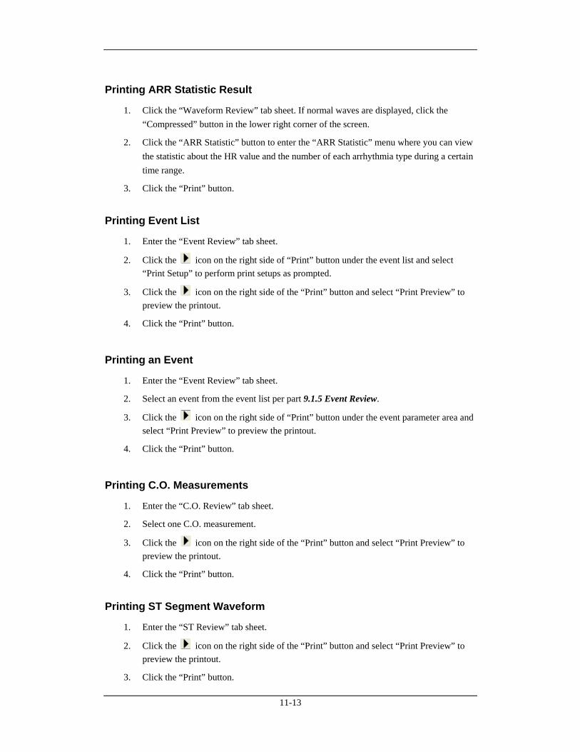
11-13
Printing ARR Statistic Result
1. Click the “Waveform Review” tab sheet. If normal waves are displayed, click the “Compressed” button in the lower right corner of the screen.
2. Click the “ARR Statistic” button to enter the “ARR Statistic” menu where you can view the statistic about the HR value and the number of each arrhythmia type during a certain time range.
3. Click the “Print” button.
Printing Event List
1. Enter the “Event Review” tab sheet.
2. Click the icon on the right side of “Print” button under the event list and select “Print Setup” to perform print setups as prompted.
3. Click the icon on the right side of the “Print” button and select “Print Preview” to preview the printout.
4. Click the “Print” button.
Printing an Event
1. Enter the “Event Review” tab sheet.
2. Select an event from the event list per part 9.1.5 Event Review.
3. Click the icon on the right side of “Print” button under the event parameter area and select “Print Preview” to preview the printout.
4. Click the “Print” button.
Printing C.O. Measurements
1. Enter the “C.O. Review” tab sheet.
2. Select one C.O. measurement.
3. Click the icon on the right side of the “Print” button and select “Print Preview” to preview the printout.
4. Click the “Print” button.
Printing ST Segment Waveform
1. Enter the “ST Review” tab sheet.
2. Click the icon on the right side of the “Print” button and select “Print Preview” to preview the printout.
3. Click the “Print” button.
11-14
Printing Real-time Waveforms
1. Enter the “ViewBed” tab sheet.
2. Click the “Print” button.
3. Select the desired waveforms from the pop-up dialog box.
4. Click the “OK” button.
or
1. Enter the “Multibed” tab sheet.
2. Click the drop-down menu button.
3. Click the “Print” button to print the displayed waveforms.
Printing 12-Lead ECG
1. Enter the 12-lead ECG analysis tab sheet from the monitor.
2. Enter the “ViewBed” tab sheet from the CMS.
3. Click the “Show Multi-lead ECG” button to display the 12-lead ECG waveforms.
4. Click the “Print” button.
5. In the pop-up dialog box, select print layout.
6. Click the “OK” button.
Printing Multi-Lead ECG
1. Enter the “ViewBed” tab sheet.
2. Click the “Show Multi-lead ECG” button to display the multi-lead ECG waveforms.
3. Click the “Print” button.
Printing EEG Waveforms (BIS module)
1. Enter the “ViewBed” tab sheet.
2. Click the “Show BIS Expand View” button to display BIS window.
3. Click “Display” button and select “EEG” from the drop-down menu.
4. Click the “Print” button.
11-15
Printing EEG Waveforms (EEG module)
1. Enter the “ViewBed” tab sheet.
2. Click the “Show EEG Expand View” button to display EEG window.
3. Click “Display” button and select “EEG” from the drop-down menu.
4. Click the “Print” button.
Printing CSA
1. Enter the “ViewBed” tab sheet.
2. Click the “Show EEG Expand View” button to display EEG window.
3. Click “Display” button and select “CSA” from the drop-down menu.
4. Click the “Print” button.
Printing ICG Hemodynamic Parameters
1. Enter the “ViewBed” tab sheet.
2. Select and then click ICG parameter area.
3. Select the “ICG” tab sheet and click the “Hemodynamic Parameters” button.
4. Click the “Print” button from the pop-up dialog box.
Printing CCO Hemodynamic Parameters
1. Enter the “ViewBed” tab sheet.
2. Select and then click CCO parameter area.
3. Select the “CCO” tab sheet and click the “Hemodynamic Parameters” button.
4. Click the “Print” button from the pop-up dialog box.
Printing SvO2/ScvO2 Oxygenation Parameters
1. Enter the “ViewBed” tab sheet.
2. Select and then click SvO2/ScvO2 parameter area.
3. Select the “SvO2” or “ScvO2” tab sheet and click the “Oxygenation Parameters” button.
4. Click the “Print” button from the pop-up dialog box.
11-16
Printing OxyCRG Graph
1. Enter the “ViewBed” tab sheet.
2. Open the “OxyCRG”window per part 7.4.16 Show/Hide OxyCRG
3. Click the “Print” button.
Printing OxyCRG Event List
1. Enter the “OxyCRG Review” tab sheet.
2. Click the icon on the right side of “Print” button under the event list and select “Print Setup” to perform print setups as prompted.
3. Click the icon on the right side of the “Print” button and select “Print Preview” to preview the printout.
4. Click the “Print” button.
Printing an OxyCRG Event
1. Enter the “OxyCRG Review” tab sheet.
2. Select an event from the event list per part 9.1.6 OxyCRG .
3. Click the icon on the right side of “Print” button under the event parameter area and select “Print Preview” to preview the printout.
4. Click the “Print” button.
Printing Alarm Settings Report
1. Enter “Alarm Setup” screen as per part 8.4 Alarm Setup.
2. Click “Print” button.
Printing Real-time Alarm
If a parameter generates an alarm when its alarm switch and print switch are set to “ON”, the CMS will initiate a real-time alarm printing
11-17
11.2.4 Printing Control By clicking “System Setup” and then selecting “Printing Control” tab, you can select local printer or network printer from the printer drop-down list. In the tab sheet, the current tasks to be printed are displayed. After selecting one task, you can:
Click the “Delete” button to delete this task.
Click the “Pause” button to pause this task.
Click the “Continue” button to resume the paused task.
Click the “Delete All” button to delete all printing tasks.
You can set up “Waveform Sweep Speed” and “Grid” in the “Print Setup” area on the right side of the sheet.
Sweep Speed: Select a sweep speed of waveform from the options of 12.5mm/s, 25mm/s and 50mm/s.
Grid: Select if print grid is printed.
You can set up the scheduled report printing in the “Scheduled Report Setup” area on the right side of the sheet.
Scheduled Report: Select or deselect the checkbox before “Scheduled Report” to switch on/off periodical report print.
Start Time: Set up the start time to print.
Interval: Set up the desired interval.
NOTE
If print fails, please restart the printer and press the button “Restart Print Service” to resume.
When network printer is selected, only printing tasks of the CMS are displayed. The printing tasks of other network are not displayed.
The "Scheduled Report Setup” function is available in trend review only when the “Scheduled Report” is ticked in “Printing Control” tab sheet.
11-18
11.3 Save as The CMS can save the following items as html files:
Graphic trends
Tabular trends
Waveform review
C.O. Review
Event list review
Event review
OxyCRG event list review
OxyCRG event review
Drug calculations
Hemodynamics calculations
Oxygenation calculations
Ventilation calculations
Renal calculations
BIS DSA
EEG DSA
CSA
With the file name defaulted as “XXXX-patient name YYYY”, in which the “XXXX” represents one of the above items. If no patient name is input, the file name will has no patient name. If it is the first time to save, the “YYYY” will be 0001, which will automatically add 1 every time data is saved. The saved files can be browsed through the Internet Explorer on other computers. The files can be saved to a mobile hard disk, flash or the like, which must be connected to the CMS before saving. If no storage device is connected, the system will give the “no valid storage device found in the system, please confirm!” prompt.
After a USB device is successfully connected to the CMS, the icon will appear in the
system icon area. To disconnect the USB device from the CMS, follow this procedure:
1. Click the icon.
2. Click the “Delete disk driver safely” prompt.
3. After the icon disappears, you can disconnect the USB device from the CMS.
11-19
Graphic Trends
1. Enter the “Trend Review” tab sheet.
2. If tabular is currently displayed on the screen, click the “Graphic” button.
3. Click the “Save As” button. A dialog box will be displayed.
4. Select a disk driver name and click “OK”. The graphic currently displayed on the screen will be saved to the designated disk (such as mobile hard disk).
Tabular Trends
1. Enter the “Trend Review” tab sheet.
2. If graphic is currently displayed on the screen, click the “Tabular” button.
3. Click the “Save As” button. A dialog box will be displayed.
4. Select a time range and click “OK”. The “Save As” dialog box will be displayed.
NOTE
The system will save the data within the time range prior to save start time.
5. Select a disk driver name and click “OK”. The data in the tabular will be saved to the designated disk (such as mobile hard disk).
Normal Waveform Review
1. E Click the “Waveform Review” tab sheet. If compressed waves are displayed, click the “Full Size” button in the lower right corner of the screen.
2. For operation details, refer to 9.1.3 Waveform Review.
3. Click the “Save As” button. The “Save As” dialog box will be displayed.
4. Select a disk driver name and click “OK”. The waveforms currently displayed on the screen will be saved to the designated disk (such as mobile hard disk).
Compressed Waveform Review
1. Click the “Waveform Review” tab sheet. If normal waves are displayed, click the “Compressed” button in the lower right corner of the screen.
2. For operation details, refer to 9.1.3 Waveform Review.
3. Click the “Save As” button. The “Save As” dialog box will be displayed.
4. Select a disk driver name and click “OK”. The waveforms currently displayed on the screen will be saved to the designated disk (such as mobile hard disk).
11-20
C.O. Review
1. Enter the “C.O. Review” tab sheet.
2. Select the C.O. measurements to be saved per part 9.1.4 C.O. Review
3. Click the “Save As” button. The “Save As” dialog box will be displayed.
4. Select a disk driver name and click “OK”. The currently selected C.O. measurements will be saved to the designated disk (such as mobile hard disk).
Event List Review
1. Enter the “Event Review” tab sheet.
2. Select “Filter by Event” and “Filter by Priority”.
3. Click the “Save As” button below the event list. The “Save As” dialog box will be displayed.
4. Select a disk driver name and click “OK”. The contents in the event list will be saved to the designated disk (such as mobile hard disk).
Event Review
1. Enter the “Event Review” tab sheet.
2. Select an event from the event list.
3. Click the “Save As” button below the event parameter area. The “Save As” dialog box will be displayed.
4. Select a disk driver name and click “OK”. The waveforms and parameters of the event will be saved to the designated disk (such as mobile hard disk).
Drug Calculation
1. Enter the “Drug Calcs” tab sheet.
2. Perform drug calculation per 10.1 Drug Calculation.
3. Click the “Save As” button. The “Save As” dialog box will be displayed.
4. Select a disk driver name and click “OK”. This set of drug calculations will be saved.
11-21
OxyCRG Event List Review
1. Enter the “OxyCRG Review” tab sheet.
2. Select “Filter by Event”.
3. Click the “Save As” button below the event list. The “Save As” dialog box will be displayed.
4. Select a disk driver name and click “OK”. The contents in the event list will be saved to the designated disk (such as mobile hard disk).
OxyCRG Event Review
1. Enter the “OxyCRG Review” tab sheet.
2. Select an event from the event list.
3. Click the “Save As” button below the trend/waveform area. The “Save As” dialog box will be displayed.
4. Select a disk driver name and click “OK”. The waveforms and parameters of the event will be saved to the designated disk (such as mobile hard disk).
Hemodynamics Calculation
1. Enter the “Hemo Calcs” tab sheet.
2. Perform hemodynamics calculation per 10.2 Hemodynamics Calculation.
3. Click the “Save As” button. The “Save As” dialog box will be displayed.
4. Select a disk driver name and click “OK”. This set of hemodynamics calculations will be saved.
Oxygenation Calculation
1. Enter the “Oxygenation Calc.” tab sheet.
2. Perform oxygenation calculation per 10.3 Oxygenation Calculation.
3. Click the “Save As” button. The “Save As” dialog box will be displayed.
4. Select a disk driver name and click “OK”. This set of oxygenation calculations will be saved.
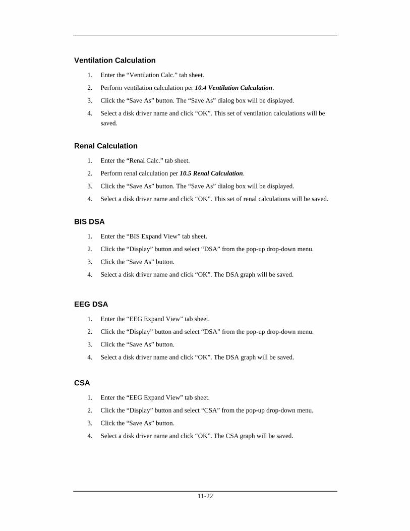
11-22
Ventilation Calculation
1. Enter the “Ventilation Calc.” tab sheet.
2. Perform ventilation calculation per 10.4 Ventilation Calculation.
3. Click the “Save As” button. The “Save As” dialog box will be displayed.
4. Select a disk driver name and click “OK”. This set of ventilation calculations will be saved.
Renal Calculation
1. Enter the “Renal Calc.” tab sheet.
2. Perform renal calculation per 10.5 Renal Calculation.
3. Click the “Save As” button. The “Save As” dialog box will be displayed.
4. Select a disk driver name and click “OK”. This set of renal calculations will be saved.
BIS DSA
1. Enter the “BIS Expand View” tab sheet.
2. Click the “Display” button and select “DSA” from the pop-up drop-down menu.
3. Click the “Save As” button.
4. Select a disk driver name and click “OK”. The DSA graph will be saved.
EEG DSA
1. Enter the “EEG Expand View” tab sheet.
2. Click the “Display” button and select “DSA” from the pop-up drop-down menu.
3. Click the “Save As” button.
4. Select a disk driver name and click “OK”. The DSA graph will be saved.
CSA
1. Enter the “EEG Expand View” tab sheet.
2. Click the “Display” button and select “CSA” from the pop-up drop-down menu.
3. Click the “Save As” button.
4. Select a disk driver name and click “OK”. The CSA graph will be saved.
12-1
12 System Setup
12.1 General Setup Clicking the “System Setup” will access a tab sheet. The CMS has three levels of setup:
Low level: “General Setup”,
Medium level: “Admin Setup”, and
High level: “Factory Setup”.
Certain authority is required if you want to modify certain setups of the system or execute certain operations. The user with lower authority cannot modify the setups of the user with higher authority, but the user with higher authority can modify the setups of the user with lower authority. When the system starts, the default setup is the “General Setup”. The “Factory Setup” is intended for use only by manufacturer-designated personnel. In the “General Setup” tab sheet, you can:
Set Alarm Volume
The system provides 11 volume levels. You can select one as required. For details, refer to 12.2.3 Alarm - Minimum Alarm Volume and 8.3 Alarm Volume.
Set Reminder Volume
You can set the reminder volume as [High], [Med] or [Low].
Telemetry Alarm Delay Setup
You can set telemetry alarm delay time (6 sec by default) and ST alarm delay time (30 sec by default). The alarms include: HR too high, HR too low, SpO2 too high, SpO2 too low, PR too high, PR too low, ST too high and ST too low.
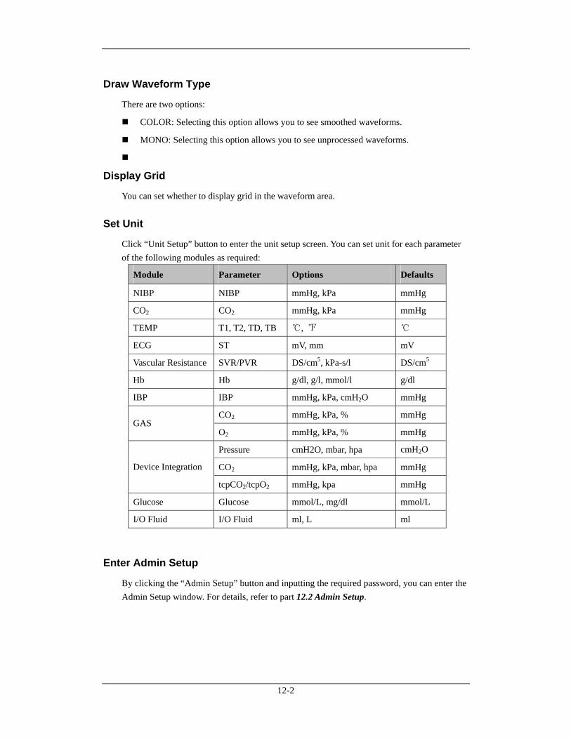
12-2
Draw Waveform Type
There are two options:
COLOR: Selecting this option allows you to see smoothed waveforms.
MONO: Selecting this option allows you to see unprocessed waveforms.
Display Grid
You can set whether to display grid in the waveform area.
Set Unit
Click “Unit Setup” button to enter the unit setup screen. You can set unit for each parameter of the following modules as required:
Module Parameter Options Defaults
NIBP NIBP mmHg, kPa mmHg
CO2 CO2 mmHg, kPa mmHg
TEMP T1, T2, TD, TB ℃, ℉ ℃
ECG ST mV, mm mV
Vascular Resistance SVR/PVR DS/cm5, kPa-s/l DS/cm5
Hb Hb g/dl, g/l, mmol/l g/dl
IBP IBP mmHg, kPa, cmH2O mmHg
CO2 mmHg, kPa, % mmHg GAS
O2 mmHg, kPa, % mmHg
Pressure cmH2O, mbar, hpa cmH2O
CO2 mmHg, kPa, mbar, hpa mmHg Device Integration
tcpCO2/tcpO2 mmHg, kpa mmHg
Glucose Glucose mmol/L, mg/dl mmol/L
I/O Fluid I/O Fluid ml, L ml
Enter Admin Setup
By clicking the “Admin Setup” button and inputting the required password, you can enter the Admin Setup window. For details, refer to part 12.2 Admin Setup.
12-3
Enter Factory Setup
By clicking the “Factory Setup” and input the required password, you can enter the Factory Setup window. As the “Factory Setup” is intended for use only by the manufacturer-designated personnel, no details will be given to it in this manual.
12.2 Admin Setup Click the “Admin Setup” button in the “General Setup” tab sheet. The“Enter Password” dialog box will pop up. After inputting the required password, select “OK” to enter a tab sheet.
12.2.1 Setting Color On the screen of the CMS, all related information of one monitored parameter appears in the same color. The related information includes real-time waveforms (including waveform name, gain and filter mode), real-time parameter values (including high and low limits), reviewed waveforms (including waveform name, gain and filter mode), etc. you can set color for each monitored parameter and ARR mark as required.
Procedure
1. Enter the “Color” tab sheet and then select a parameter or ARR mark you want to change its color.
2. Click the color box corresponding to the parameter or ARR mark, and a list of available colors will be displayed.
3. Select your desired color from the list.
4. If you want a color that is not in the list, click “Other” to enter the window, through which you can define a color you want.
5. Select a color and click “OK”.
12.2.2 Display Setup You can set screen size, number of main screen /display layout, multibed display, multibed window layout, and auxiliary window.
Screen Size
1. Click the “Display Setup” tab.
2. Select the display type from the “Screen Size” drop-down menu.
3. Click the “Close” button.
4. Your choice will take effect after the system restarts.
12-4
The CMS supports up to 4 displays at one time. It will check the number of displays every time it starts. When more than one display is used simultaneously, they should adopt the same screen size and resolution. To ensure the normal operation of the CMS, you should select the screen size of the display actually used and the display resolution should be set to 1280 x 1024 pixels. Setting resolution to other pixels may cause display error.
Number of Main Screen / Display Layout
Select a number for the item “Number of Main Screen” to change the displaying mode, if the CMS is equipped with 2 displays:
If “1” is selected, there is only one main screen which always to display multibed window. The other display is the auxiliary screen, always for single bed window and system menu.
If “2” is selected, the two screens are both able to be used as main screen. If viewing a single bed, the single bed window will be shown in the auxiliary display; if not, the two screens will both show multibed window.
If a CMS is equipped with 4 displays, select the option of“1*4” or “2*2” for “Display Layout” to change the mouse route.
NOTE
The change of display settings will be effected after the CMS restarts.
Multibed Display
Select/deselect the check box before “Measurement Units” to show/hide parameter units on the multibed screen.
Select/deselect the check box before “Patient Name” to show/hide patient name on the multibed screen.
In “Name Displaying Hotkey”, you can set the hotkey which can be used to display name in the first waveform area of patient window on the multibed screen. The default hotkey is F9. If the check box before “Patient Name” is not ticked, the patient’s name displays when you press the hotkey. The name does not display after 30 seconds or when you press the hotkey again.
In “Change to Idle Sector”, you can configure the switch of setting to an idle sector in multibed screen:
If “Enable” is selected, the drop-down list of “No Patient Admitted” bed on multibed screen will display the option “Change to Idle Sector”;
If “Disable” is selected, the drop-down list of “No Patient Admitted” bed on multibed screen will not display the option “Change to Idle Sector”.
12-5
Multibed View Window Layout
You can select the number of rows and columns for multibed view window based on the actual needs. The range for the number of rows is 2 to 8 and that for the number of columns is 1 to 3. The product of the number of rows and that of columns is the number of patient sectors. The number of patient sectors on a single screen cannot exceed 16. After the number of rows and that of columns are selected, you can preview the new layout set on the right side of the screen. After the number of rows and that of columns are selected, the setting of multibed view window layout takes effect.
ECG Lead Sequence
You can choose one option from “Standard” and “Cabrera” for “ECG Lead Sequence” to set waveform sequence in 12-lead review. The waveforms in screen, report, strip, exported XML file will be arranged according to the selected option. The waveform sequences of each option are:
Standard: I, II, III, aVR, aVL, aVF, V1, V2, V3, V4, V5, V6
Cabrera: aVL, I, -aVR, II, aVF, III, V1, V2, V3, V4, V5, V6
NOTE
Only a CMS has 12-lead review, the setting of ECG lead sequence can take effect.
Auxiliary Window Setup
Auxiliary window setup means to set the tab sheets on the single bed window. The six functional items of patient management, viewbed, waveform review, trend review, alarm review and display setup are fixed to be selected while OxyCRG review, ST review, C.O. review, drug calculation, hemodynamic calculation, OxyCRG calculation, renal calculation and ventilation calculation are user selectable. You can change the display order of the functional items via the “Move Up”, “Move Down”, “Move First” and “Move Last” buttons on the right side of the dialog box. After the functional items are set, click “OK” to activate the setting.
12-6
12.2.3 Alarm Click “Alarm” to open a dialog box.
Minimum Alarm Volume
The minimum alarm volume level can be set from 0 to 10.
Switch on/off Reminder Tone and Set its Interval
The “Reminder Tone” can be set to “On” or “Off”. When it is set to “On”, in the status of CMS system silence or audio alarm off, the CMS can give a kind of reminder tone in case of an active alarm condition. When it is set to “Off”, the reminder tone will not be produced. You can set the reminder interval as “1 min”, “2 min” or “3 min”. The default one is “1 min”. Alarm Off Reminder Tone is same as the highest level alarm tone.
Silence Hotkey
For details, refer to 8.10 CMS System Silence.
Set Alarm Audio Mode
You can set the alarm audio mode as “ISO”, “MODE 1” or “MODE 2”.
Set Alarm Sound Intervals
If the alarm audio mode is set as “ISO”, you can set alarm sound intervals by toggling between “High Alarm Interval (s)”, “Med Alarm Interval (s)” and “Low Alarm Interval (s)”. You cannot change the interval between alarm tones if you choose mode 1 or 2 as your desired alarm audio mode. For these two modes, the interval between alarm tones identifies the alarm levels as follows:
Mode 1:
Interval between high level alarm tones: continuously.
Interval between medium level alarm tones: 5 s.
Interval between low level alarm tones: 20 s.
Mode 2:
Interval between high level alarm tones: 1 s.
Interval between medium level alarm tones: 5 s.
Interval between low level alarm tones: 20 s.

12-7
Select Stored Waveforms
In the “Alarm” tab sheet, you can select the relevant waves stored when alarms occurred to the specific parameter.
1. Click the “Alarm” tab sheet.
2. Select a parameter from the “Alarm Numeric” list. Then select the relevant wave stored from the “Related Waveform” when the alarm occurred.
3. Click “Save” to save the selected wave.
4. Click “Default” to restore all parameters to the default configuration.
NOTE
No matter how many waveforms are selected from the Related Waveform list, the system can at most save 3 waveforms and record 2 waveforms for one parameter when an alarm occurs.
Your selections are only effective for later alarms. For already existed alarms, it is unnecessary to re-select waveforms.
12.2.4 Trend Group You can set the parameters in “Trend Review” by group. The trend group tab sheet contains system default trend groups list and custom trend groups list, and the list of corresponding trend group member parameters as well. The system provides ten (10) default trend groups, which are “All”, “Standard”, “ECG”, “GAS”, “Hemodynamic”, “RM”, “BIS”, “EEG”, “Ventilator” and “Anesthesia”. You cannot edit the default trend groups.
Create trend group: click “New Group” and enter the name of custom trend group in the pop-up dialog box.
Edit trend group: after selecting custom trend group, you can select/deselect the member parameters or adjust the order of member parameters in the list.
Save trend group: after creating or editing trend group, click “Save Group” to save the new or modified trend group.
Delete trend group: you can delete any custom trend group from the trend group list.
Rename trend group: click the custom trend group to be renamed, enter the new name of the trend group in the pop-up dialog box.
12-8
12.2.5 Monitor List Clicking the “Monitor List” will enter a tab sheet, which lists all the monitors in the LAN including the monitors admitted by this CMS. The displayed items are: monitor name, unit, bed no., IP address and monitoring status. The patient can be admitted by the CMS only after the monitor is admitted by the CMS.
Refresh
You can update the list by clicking the “Refresh” button.
Admit
You can select the monitor with the monitoring status of “Not admitted by CMS” and then click the “Admit” button to admit it to this CMS.
Cancel
You can select the monitor with the monitoring status of “Admitted by this CMS” and then click the “Cancel” button to cancel the admission.
Cancel All
You can click the “Cancel All” button to cancel this CMS’s admission of all the monitors.
Admit All Current Unit's Monitors
You can admit all current unit’s monitors to this CMS by clicking the “Admit All Current Unit's Monitors” button. If “Auto Admit All Current Unit's Monitors” is selected, the admission can be done automatically.
12-9
12.2.6 Log Clicking the “Log” tab will enter a tab sheet, which records the operating status of the CMS providing the convenience for the service personnel to track and maintain the system. Each log includes occurrence time, log level, and log description.
Delete
You can delete all logs by clicking the “Delete All” button.
Refresh
You can update the logs by clicking the “Refresh” button.
Export
1. Click the “Export” button. The “Save As” dialog box will be displayed.
2. Select a disk to which the logs are exported. The disk can be a floppy disk, local hard disk, mobile hard disk or USB.
3. The default file name is “cmsXXXX”. If it is the first time to save, the “XXXX” will be 0001, which will automatically add 1 every time log is saved. You can change the file name as required.
4. Click “OK” to initiate exporting data.
5. Click “Cancel” to cancel exporting data.
12-10
12.2.7 Telemetry If your CMS is connected with telemetry monitors, select the “Telemetry” tab, you can set the following items in an opened tab sheet.
Alarm Level Setup
Click the “Alarm Level Setup” button. In the popup menu, you can set the “Alm Lev of ECG Lead Off”, “Alm Lev of SpO2 Sensor Off” and “Alm Lev of No RF signal” to “High”, “Med” or “Low”. The default setting is “Low”.
Monitoring Mode Setup
Monitoring mode setup means to establish corresponding relations between the telemetry transmitter and multibed patient sector. The CMS provides two monitoring modes: Fixed monitoring: to establish fixed corresponding relations between the telemetry transmitter and multibed patient sector. Such corresponding relations are not changed when the patient is discharged. The patient sector displays bed number and serial number of telemetry transmitter and the bed mark color is not changed. The patient sector displays “No Patient Admitted”. Flexible monitoring: no fixed corresponding relations are established between the telemetry transmitter and multibed patient sector. The corresponding relations are relieved when the patient is discharged. The patient sector is idle and displays “Idle sector. Click to admit a patient”. Click the “Monitoring Mode Setup” button and select the telemetry monitoring mode from the pop-up menu. The options are “Fixed Monitoring” and “Flexible Monitoring”. The setting is activated immediately.
System Information
In the “System Information” area, the mainboard software version, receiveboard software version, total run-time are displayed.
12-11
Frequency Setup
Select frequency range
1. You can select the appropriate frequency segment from “Freq Segment”. The minimum “Start Freq” and maximum “End Freq.” corresponding to the frequency segment will be displayed automatically.
2. You can also click the drop-down menu to select other “Start Freq” and “End Freq.”.
Frequency setup list
This area shows channel number, channel name, and the transmitter frequency and signal strength corresponding to each receiver channel in the tabular form.
1. Select a channel from the list. If a frequency point is currently available and it is not used by other channel, you can click the “Program…” button to program this channel.
2. If the serial port connects no corresponding transmitter at this time, the message will be displayed.
3. If the serial port is properly connected with the corresponding transmitter, the Program screen will be displayed.
The default value of “SN” is the serial number that has been written in the transmitter.
The default value of the “Frequency” is the transmitter frequency corresponding to the current receiver channel. You can either select other frequency by clicking the drop-menu button.
The default value of “Power” is 23. You can either select other power value by clicking the drop-menu button.
4. Select “OK”, and you will modify the configuration of this transmitter.
5. After the configuration is completed, click “OK” in the following dialog box.
Discharge a patient
Select a channel from the frequency setup list. If this channel has admitted a patient, you can click the “Discharge” button to discharge the patient.
Settings of Lethal Arrh. OFF
The “Lethal Arrh. Off” can be set for telemetry monitoring system.
If it is set to “Disable”, the switches of all lethal Arrhythmia alarms are set to “ON” and unchangeable. “All Alarm Off” button is inactive.
If it is set to “Enable”, the switches of lethal Arrhythmia alarms are able to be set. “All Alarm Off” button is active.
12-12
Nurse Call and Event Setup
To enable or disable nurse call and/or event function on telemetry monitoring system, you can make the following settings.
If “Enable” is selected, the telemetry system will enable nurse call and event functions, and patient mgmt. screen will display the setting items of “Nurse Call” and “Event”.
If “Nurse Call” is selected, the telemetry system will enable nurse call function, and the patient mgmt. screen will display the setting item of “Nurse Call”.
If “Event” is selected, the telemetry system will enable event function, and the patient mgmt. screen will display the setting item of “Event”.
If “Disable” is selected, the telemetry system will disable nurse call and event functions there are no setting items of “Nurse Call” and “Event” in the patient mgmt. screen.
Nurse Call Audio Mode
You can set the nurse call audio mode as “ISO”, “MODE 1” or “MODE 2”.
IP Address
You can set the IP address of telemetry receiver. When the IP address is changed, click “Modify” button to save the change.
12.2.8 Other Clicking the “Other” tab will enter a tab sheet. In this tab sheet, you can turn on or off the following options:
Shutdown Requires Password: If this option is turned on, you need to input a password before shutting down the system.
Change Language
Change User Password
Change Time
Change Hospital Name
Database Backup and Recovery
Gateway Communication Setting
Multi-CMS Communication Settings
Remote Control Setting

12-13
Change Language
The CMS enables multiple languages, from which you can choose any one as required. When the CMS starts, the default language is the language selected at time of installation.
1. Click the “Change Language” button. The dialog box will be displayed.
2. Click the down arrow button to drop down a list of available languages, from which you can select your desired language. The available languages are the ones registered at time of installation and supported by the operating system.
3. Click the “OK” button.
4. If the language you have selected is not supported by the operating system, a message will be displayed. You can follow it.
NOTE
If the language you selected is inconsistent with that of the operating system, unrecognizable characters may occur to the CMS. Therefore, change the language and region settings of the operating system by following the operator’s manual of the operating system.
Change User Password
1. Click the “Change User Password” button. The dialog box will be displayed.
2. Input old password and new password before selecting “OK”.
3. If the change succeeds, the “Password changed, please remember new password” message box will be displayed. Select “OK” to activate you change.
4. If the old password you have entered is incorrect or the new password is entered inconsistently, the system will give a prompt message. You can select “OK” to repeat the input procedure.
NOTE
If you use factory password to enter the “Admin Setup” tab sheet, you can directly input new password without inputting old password.
12-14
Change Time
WARNING
Directly changing the system time (automatically or manually) of the operating system on which the CMS is installed may cause saved data missing on the CMS. Change the time only from the CMS.
NOTE
After the CMS time is changed, the CMS will synchronize the time of networked monitors.
When a monitor is connected to the CMS, the CMS will synchronize the time of the monitor.
The CMS will synchronize the time of the networked monitors on its whole hours.
The system time of the defibrillator will not be synchronized by the CMS.
The system time can be changed automatically or manually.
Automatically change time
1. Click “Change Time” button, and the dialog box will be displayed.
2. Set “Time Synchronization” to “On”.
3. Input master time server IP and second time server IP.
4. Click “OK.”.
Manually change time
1. Click the “Change Time” button, and the dialog box will be displayed.
2. Set “Time Synchronization” to “Off”.
3. Adjust the setting of “Set System Time”: For year, month and date, you can either click them one after another to highlight the number and then use the keyboard to enter the number you want manually, or click the down arrow button to open the time table and then select from the table.
4. For hour, minute and second, you can either click them one after another to highlight the number and then use the keyboard to enter the number you want manually, or click the up or down arrow button to make changes.
5. Click “OK”.
12-15
Change Hospital Name
1. Click the “Change Hospital Name” button.
2. Input hospital name and unit name.
3. Select “OK”.
NOTE
Hospital name should be within 128 characters,and department name be within 8 characters.
Auto Shrink Database
Shrink Database provides ability to clear up the invalid data in database and release storage space. The system requires shrinking database every day. The default time of auto database shrink is set to zero hour (00:00:00). You can set to other desired time upon needs. The operation is as follows:
1. Click “Auto Shrink Database” button.
2. Input the preset time for auto database shrink.
3. Click “OK”.
Gateway Communication Setting
Gateway communication setting menu provides three (3) tabs which are Network Setup, Authorization Setup and Service Setup.
Network Setup
The “Network Setup” tab sheet lists the information about the network adapters configured on the CMS. One of the network adapters is for internal communication within the CMS and beside monitors; the other network adapter is for inter-communication between CMS and other systems. Select and activate one network adapter, the communication between the CMS and other systems is established. To activate a network adapter:
1. Select the network adapter type to be activated.
2. Select one IP address as required if there are multiple IP addresses in the “IP Address” area on the right.
3. Click “OK”.
When a network adapter has been activated, the network card type and IP address background color is light gray.
12-16
Authorization Setup
The CMS “Authorization Setup” menu lists the departments and bed numbers of all bedside monitors within the CMS. If the check boxes before the department and bed number are selected, other systems networked with this CMS are authorized to view the patient. If the check boxes before the department and bed number are not selected, other systems networked with this CMS are not authorized to view the patient.
Service Setup
The “Service Setup” tab sheet lists CMS+ to Elan translator , Gateway Communication Settings, ADT query and data export setup items: CMS+to Elan Translator The options are “Enable” and “Disable”. When “Disable” is selected, all items in “Gateway Communication Settings”, “ADT Query Setup” and “Data Export Setup” are grey, and the CMS does not communicate with Gateway. Gateway Communication Settings You can set the CMS’ communication mode with the Gateway.
If “Multicast” is selected, the CMS communicates with Gateway in multicast mode.
If “Unicast” is selected, the CMS communicates with the specified Gateway in unicast mode. “IP Address” shall be the address of Gateway, and setting of “Port ” shall be consistent with that set in Gateway.
ADT Query Setup “ADT Query”switch, and the“IP Address”and “Port” for communicating with Gateway can be set here. When “ADT Query” is set to “Enable”, the“IP Address”and “Port”can be edited. “IP Address”shall be the address of Gateway, and setting of “Port ”shall be consistent with that set in Gateway.
NOTE
The "Obtain Patient Information" button is available on the patient management screen only when“ADT Query”is set to “Enable”.
12-17
Date Export Setup
Input multicast IP address and port. “IP Address” shall be the address of Gateway, and setting of “Port ” shall be consistent with that set in Gateway.
Export Waveform Data: When configured to “ON”, the button “Export to EMR” will be displayed on the “Waveform Review” (normal waveform review screen) and “Event Review” sheets, and the waveform or event can be exported to other systems. When configured to “Off”, the waveform or event can not be exported to other systems.
Export 12-Lead ECG Report: When configured to “On”, once the CMS receives 12-lead ECG analysis result from bedside monitor, the CMS will automatically generate a 12-lead ECG report, and send the report to other systems. When configured to “Off”, the report will not be generated.
Multi-CMS Communication Settings
Multi-CMS Communication Settings menu is used to add or delete the IP address of other CMS. You can view other beds on that CMS only when the corresponding IP address of a CMS is added.
1. Click the “Multi-CMS Communication Settings” button and open the “Communication Settings” menu.
2. Click “Add”, and then input the IP address of a CMS on which you want to proceed viewing other beds in the opened dialog box.
3. Click “OK”.
NOTE
As for the CMSs or monitors which only have broadcast mode to implement remote CMS, it is required to tick the “Broadcast send mode” checkbox.
Remote Control Settings
In Remote Control Settings menu, you can make the following settings:
Alarm Paused & Silence: Select the checkbox before “Alarm Paused & Silence” to switch on/off alarm paused or silence. If the checkbox is selected, you can remotely control the operations of alarm paused or silence on bedside monitors. So the corresponding controls are available in the drop-down menu of spot patient window and the icons in the button area of ViewBed screen are active. If the checkbox is not selected, you can not use those functions.
12-18
Alarm Setup: Select the checkbox before “Alarm Setup” to switch on/off remote alarm setup. If the checkbox is selected, you can remotely change the settings of activation state, alarm priority, alarm high/low limit, ARR threshold, Apnea alarm time and Desat limit on the monitor. If the checkbox is not selected, you can not change those settings on the monitor.
Alarm Latched: Select the checkbox before “Alarm Latched” to turn on or turn off alarm latched function. When “Alarm Latched” is selected, you can remotely control to enable
the alarm latched function is enabled. Click the button in viewbed window and the
“Alarm Setup” menu will pop up. The options of “Alarm Latched” in the menu are active. When “Alarm Latched” is not selected, the alarm latched function is disabled.
Privacy Mode: Select the checkbox before “Privacy Mode” to turn on/off this function. When “Privacy Mode” is selected, you can remotely control the bedside monitor to enter privacy mode. The corresponding control is available in the drop-down menu of spot patient window. If it is not selected, you can not use this function. The corresponding control is unavailable in the drop-down menu of spot patient window.
Night Mode: Select the checkbox before “Night Mode” to turn on/off this function. When “Night Mode” is selected, you can remotely control the bedside monitor to enter night mode. The corresponding control is available in the drop-down menu of spot patient window. If it is not selected, you can not use this function. The corresponding control is unavailable in the drop-down menu of spot patient window.
NOTE
When the CMS restarts, the “Alarm Setup”, “Alarm Paused & Silence”, “Alarm Latched”, “Privacy Mode” and “Night Mode” checkboxes remain the same as the CMS is last turned off.
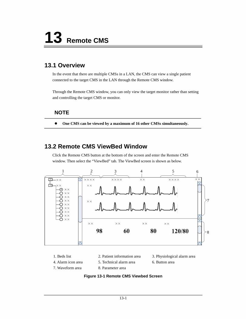
13-1
13 Remote CMS
13.1 Overview In the event that there are multiple CMSs in a LAN, the CMS can view a single patient connected to the target CMS in the LAN through the Remote CMS window. Through the Remote CMS window, you can only view the target monitor rather than setting and controlling the target CMS or monitor.
NOTE
One CMS can be viewed by a maximum of 16 other CMSs simultaneously.
13.2 Remote CMS ViewBed Window Click the Remote CMS button at the bottom of the screen and enter the Remote CMS window. Then select the “ViewBed” tab. The ViewBed screen is shown as below.
1. Beds list 2. Patient information area 3. Physiological alarm area 4. Alarm icon area 5. Technical alarm area 6. Button area 7. Waveform area 8. Parameter area
Figure 13-1 Remote CMS Viewbed Screen
1 2 3 6
7
4 5
8
13-2
13.2.1 Beds List The beds list displays the information about all CMSs and networked bedside monitors (target monitors) in the same network segment of an LAN. When the “Remote CMS” screen is accessed, the CMS will automatically list other CMSs which can be operated remotely. Only when the CMSs’IP addresses are added in the Multi-CMS Communication Settings menu, the names of the corresponding CMSs will be automatically displayed in the list. In the beds list, the first-level nodes are the unit names of the CMSs; the second-level nodes are the monitors connected to the CMSs. Generally, the name of the second-level node is department, bed number or patient name. You can select the target monitor to be viewed by selecting the radio button before the second-level node, or the monitor. The background color indicates the status of the target monitor.
White: indicates that no alarm occurs to the target monitor.
Red: indicates that a high level alarm, nurse call or event occurs to the target monitor.
Yellow: indicates that a medium or low level alarm occurs to the target monitor.
Grey: indicates that the target monitor is in standby status.
Light Grey: indicates that the target monitor is in offline status.
13.2.2 Physiological Alarm Area This area is to display physiological alarm messages and relevant text coming from the viewed target monitor circularly. The display rule is same as that in physiological alarm area of patient window. Please refer to 6.2.3.5 Physiological Alarm Area. Different background colors are used to indicate the alarm priorities.
Red: indicates that a high level alarm occurs to the target monitor.
Yellow: indicates that a medium or low level alarm occurs to the target monitor.
13.2.3 Technical Alarm Area This area is to display technical alarm messages or prompt messages circularly coming from the viewed target monitor. The display rule is same as that in the technical alarm of patient window. Please refer to 6.2.3.4 Technical Alarm Area.
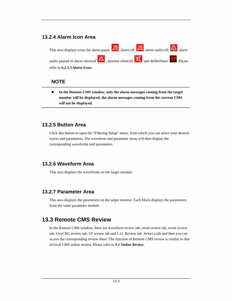
13-3
13.2.4 Alarm Icon Area
This area displays icons for alarm pause , alarm off , alarm audio off , alarm
audio paused or alarm silenced ,monitor silenced and defibrillator . Please
refer to 6.2.3.3 Alarm Icons.
NOTE
In the Remote CMS window, only the alarm messages coming from the target monitor will be displayed; the alarm messages coming from the current CMS will not be displayed.
13.2.5 Button Area Click this button to open the “Filtering Setup” menu, from which you can select your desired waves and parameters. The waveform and parameter areas will then display the corresponding waveforms and parameters.
13.2.6 Waveform Area This area displays the waveforms on the target monitor.
13.2.7 Parameter Area This area displays the parameters on the target monitor. Each block displays the parameters from the same parameter module.
13.3 Remote CMS Review In the Remote CMS window, there are waveform review tab, trend review tab, event review tab, OxyCRG review tab, ST review tab and C.O. Review tab. Select a tab and then you can access the corresponding review sheet. The function of Remote CMS review is similar to that of local CMS online review. Please refer to 9.1 Online Review.
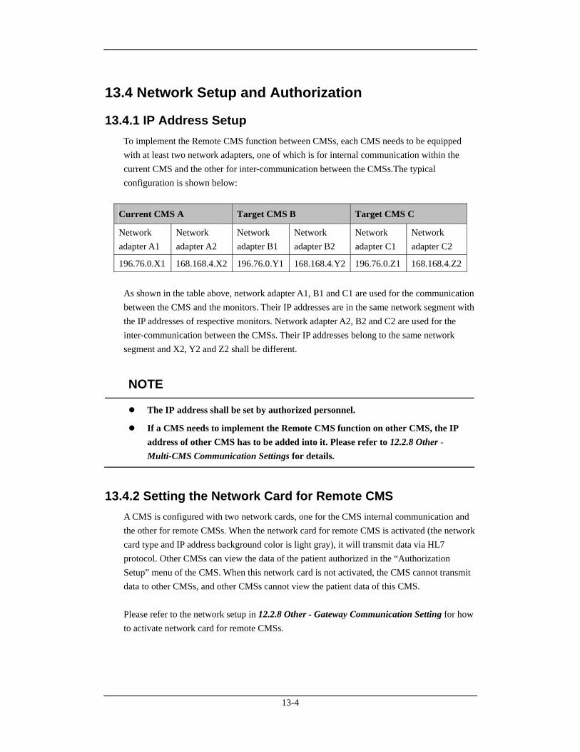
13-4
13.4 Network Setup and Authorization
13.4.1 IP Address Setup To implement the Remote CMS function between CMSs, each CMS needs to be equipped with at least two network adapters, one of which is for internal communication within the current CMS and the other for inter-communication between the CMSs.The typical configuration is shown below:
Current CMS A Target CMS B Target CMS C
Network adapter A1
Network adapter A2
Network adapter B1
Network adapter B2
Network adapter C1
Network adapter C2
196.76.0.X1 168.168.4.X2 196.76.0.Y1 168.168.4.Y2 196.76.0.Z1 168.168.4.Z2
As shown in the table above, network adapter A1, B1 and C1 are used for the communication between the CMS and the monitors. Their IP addresses are in the same network segment with the IP addresses of respective monitors. Network adapter A2, B2 and C2 are used for the inter-communication between the CMSs. Their IP addresses belong to the same network segment and X2, Y2 and Z2 shall be different.
NOTE
The IP address shall be set by authorized personnel.
If a CMS needs to implement the Remote CMS function on other CMS, the IP address of other CMS has to be added into it. Please refer to 12.2.8 Other - Multi-CMS Communication Settings for details.
13.4.2 Setting the Network Card for Remote CMS A CMS is configured with two network cards, one for the CMS internal communication and the other for remote CMSs. When the network card for remote CMS is activated (the network card type and IP address background color is light gray), it will transmit data via HL7 protocol. Other CMSs can view the data of the patient authorized in the “Authorization Setup” menu of the CMS. When this network card is not activated, the CMS cannot transmit data to other CMSs, and other CMSs cannot view the patient data of this CMS. Please refer to the network setup in 12.2.8 Other - Gateway Communication Setting for how to activate network card for remote CMSs.
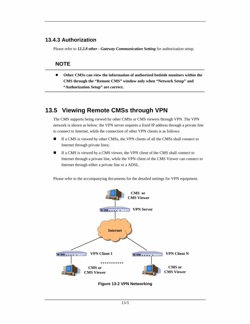
13-5
13.4.3 Authorization Please refer to 12.2.8 other - Gateway Communication Setting for authorization setup.
NOTE
Other CMSs can view the information of authorized bedside monitors within the CMS through the “Remote CMS” window only when “Network Setup” and “Authorization Setup” are correct.
13.5 Viewing Remote CMSs through VPN The CMS supports being viewed by other CMSs or CMS viewers through VPN. The VPN network is shown as below: the VPN server requires a fixed IP address through a private line to connect to Internet, while the connection of other VPN clients is as follows:
If a CMS is viewed by other CMSs, the VPN clients of all the CMSs shall connect to Internet through private lines;
If a CMS is viewed by a CMS viewer, the VPN client of the CMS shall connect to Internet through a private line, while the VPN client of the CMS Viewer can connect to Internet through either a private line or a ADSL.
Please refer to the accompanying documents for the detailed settings for VPN equipment.
VPN Server
VPN Client 1 VPN Client N
Internet
CMS or CMS Viewer
CMS orCMS Viewer
CMS orCMS Viewer
Figure 13-2 VPN Networking
13-6
When the VPN network is set up, you can directly connect one of the network interface cards of the CMS with LAN port of VPN, or connect them through switching equipment, and set correct IP address for the CMS. When you use Remote CMS function to view other CMSs in VPN network, you need to add the IP addresses of other CMSs in Multi-CMS Communication Settings menu. Please refer to 12.2.8 Other - Multi-CMS Communication Settings for details.
NOTE
If there are two network cards installed on the host of the CMS, please differentiate the network card for bedside monitor from the card for multiple CMSs / CMS Viewer / other information systems, and set correct IP addresses for the corresponding network cards.
If there are two network cards installed on the host of the CMS, please respectively connect them with the corresponding network according to their specific usage.
Do not connect two network cards in the same network segment at one time. For example, you can not connect two network cards with bedside monitors’ network.
14-1
14 Database Backup and Recovery
14.1 Overview The CMS provides database backup and recovery. The CMS will shut off automatically during database backup and recovery. You can start database backup and recovery by operating the CMS or the Windows operating system, or when you fail to log in the database.
By operating the CMS
Enter the “Admin Setup” menu; select “Other” to open a tab sheet. Click the “Database Backup and Recovery” button and a message box will pop up. Select “Yes”, the CMS will automatically shut off and start database backup and recovery.
NOTE
Take care to perform database backup and recovery. This will automatically shut off the CMS.
When the CMS fails to log in the database
The CMS will automatically log in the database when it starts. If it fails to log in the data base, a message box will pop up. Click the “Restart” button to restart the CMS; select the “Recover” button to backup and recover the database.
By operating the Windows operating system
Click the “Start” button of the Windows operating system; select “Programs” and then select “Database Backup and Recovery” to run the database backup and recovery program.
14-2
14.2 Backup Database
14.2.1 Select Operation Type When you run the “Database Backup and Recovery” program, a dialog will pop up for you to select the operation type. Select “Backup Database”.
14.2.2 Select Backup Path You can backup the database on the local hard disk or on a USB disk. Select a path from the drop-down list. The available hard disk partitions are listed automatically and a directory in which the backup file is stored is created automatically.
NOTE
Do not modify the directory of the backup file. It is specified by the system.
The directory is named YYYYMMDDhhmmbak, in which YYYY refers to the year, MM refers to the month. DD refers to the date, hh refers to the hour and mm refers to the minute.
14.2.3 Backup Database After selecting the backup path, click the “Next” button, a dialog box will appear. Click the “Start” button to start database backup. If database backup is overtime or an abnormal condition occurs during database backup, a message will be presented. If the backup database is stored on the local hard disk, the old backup file will be deleted automatically so that only one backup file is stored on the local hard disk. If the backup is stored on the USB disk, the old one will not be deleted.
14-3
14.3 Recover Database
CAUTION
The recovered database will overwrite the current one. Make sure whether you need to backup the current database before carrying out database recovery.
NOTE
If the CMS cannot start normally due to database error resulting from abnormal shutoff or improper operation, recover the database.
14.3.1 Select Operation Type After the “Database Backup and Recovery” program starts up, the dialog box will appear. Select “Recover Database”.
14.3.2 Select Path You can recover the database from local hard disk or from a USB disk. If you select local hard disk, the system will search the correct backup database for recovery on the local hard disk.
If you select the USB mobile medium, click the button and select the backup file for
recovery.
14.3.3 Recover Database After selecting the correct path for database recovery, select the “Next” button to enter a dialog box. Then click the “Start” button to start database recovery. If database recovery is overtime or an abnormal condition occurs during database recovery, a message will be presented.
14-4
14.4 Rebuild Database After the “Database Backup and Recovery” program starts up, the dialog box will appear. Select “Rebuild Database”.
NOTE
All the data in the current database will be deleted during rebuilding the database.
14.5 Shrink Database After the “Database Backup and Recovery” program starts up, the dialog box will appear. Select “Shrink Database”. If an abnormal condition occurs during database shrink, a message will be presented.
14.6 Exit Database Backup and Recovery When you exit the “Database Backup and Recovery” program, the CMS will start automatically.
15-1
15 System Help
15.1 Overview The CMS features a webpage-like on-line help so that you can obtain a better understanding of the system. Click the “Help” menu to enter the help screen. There are three icons on top left of the Help screen:
: Page down.
: Page up.
: Return to the screen as shown in the above figure.
: Display copyright information, including system software version, system software and database copyright information and so on.
NOTE
The help information on the CMS is not only about the system itself, but also on a number of concepts and operations related to bedside monitors.
You can enter corresponding help information by selecting any of the following three links:
Introduction: Brief introduction to the CMS and its configuration.
Operation Introduction: Introduction to various operations of the CMS, such as multi-bed and viewbed observation.
Bio Essentials: Introduction to monitoring function of each parameter module, such as ECG, SpO2, etc.

15-2
FOR YOUR NOTES
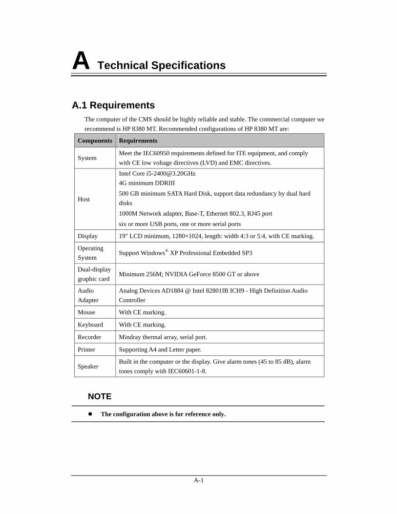
A-1
A Technical Specifications
A.1 Requirements The computer of the CMS should be highly reliable and stable. The commercial computer we recommend is HP 8380 MT. Recommended configurations of HP 8380 MT are:
Components Requirements
System Meet the IEC60950 requirements defined for ITE equipment, and comply with CE low voltage directives (LVD) and EMC directives.
Host
Intel Core [email protected] 4G minimum DDRIII 500 GB minimum SATA Hard Disk, support data redundancy by dual hard disks 1000M Network adapter, Base-T, Ethernet 802.3, RJ45 port six or more USB ports, one or more serial ports
Display 19" LCD minimum, 1280×1024, length: width 4:3 or 5:4, with CE marking.
Operating System
Support Windows® XP Professional Embedded SP3
Dual-display graphic card
Minimum 256M; NVIDIA GeForce 8500 GT or above
Audio Adapter
Analog Devices AD1884 @ Intel 82801IB ICH9 - High Definition Audio Controller
Mouse With CE marking.
Keyboard With CE marking.
Recorder Mindray thermal array, serial port.
Printer Supporting A4 and Letter paper.
Speaker Built in the computer or the display. Give alarm tones (45 to 85 dB), alarm tones comply with IEC60601-1-8.
NOTE
The configuration above is for reference only.
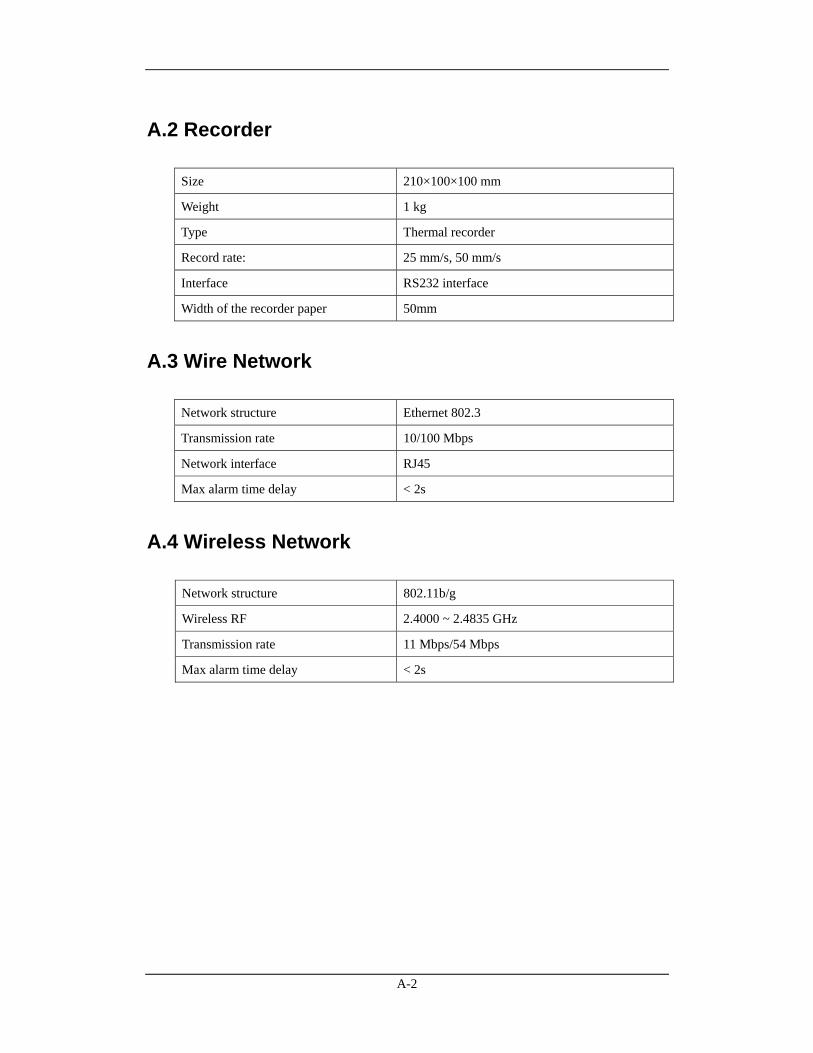
A-2
A.2 Recorder
Size 210×100×100 mm
Weight 1 kg
Type Thermal recorder
Record rate: 25 mm/s, 50 mm/s
Interface RS232 interface
Width of the recorder paper 50mm
A.3 Wire Network
Network structure Ethernet 802.3
Transmission rate 10/100 Mbps
Network interface RJ45
Max alarm time delay < 2s
A.4 Wireless Network
Network structure 802.11b/g
Wireless RF 2.4000 ~ 2.4835 GHz
Transmission rate 11 Mbps/54 Mbps
Max alarm time delay < 2s
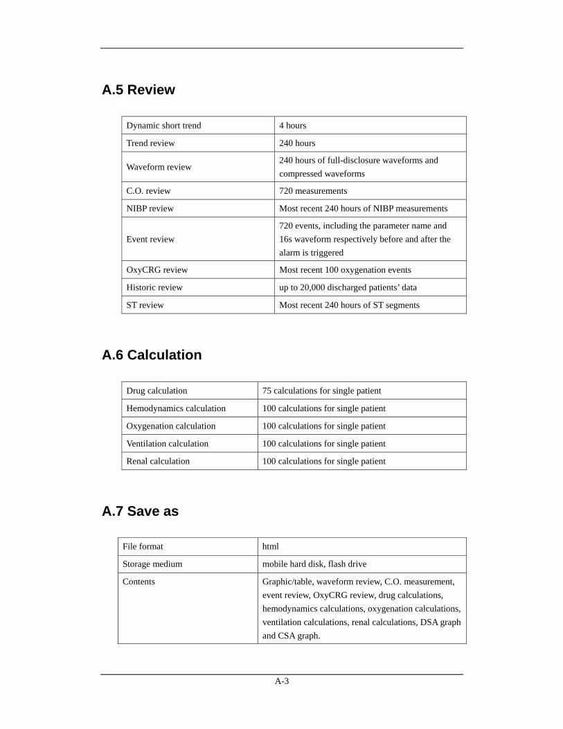
A-3
A.5 Review
Dynamic short trend 4 hours
Trend review 240 hours
Waveform review 240 hours of full-disclosure waveforms and compressed waveforms
C.O. review 720 measurements
NIBP review Most recent 240 hours of NIBP measurements
Event review 720 events, including the parameter name and 16s waveform respectively before and after the alarm is triggered
OxyCRG review Most recent 100 oxygenation events
Historic review up to 20,000 discharged patients’ data
ST review Most recent 240 hours of ST segments
A.6 Calculation
Drug calculation 75 calculations for single patient
Hemodynamics calculation 100 calculations for single patient
Oxygenation calculation 100 calculations for single patient
Ventilation calculation 100 calculations for single patient
Renal calculation 100 calculations for single patient
A.7 Save as
File format html
Storage medium mobile hard disk, flash drive
Contents Graphic/table, waveform review, C.O. measurement, event review, OxyCRG review, drug calculations, hemodynamics calculations, oxygenation calculations, ventilation calculations, renal calculations, DSA graph and CSA graph.
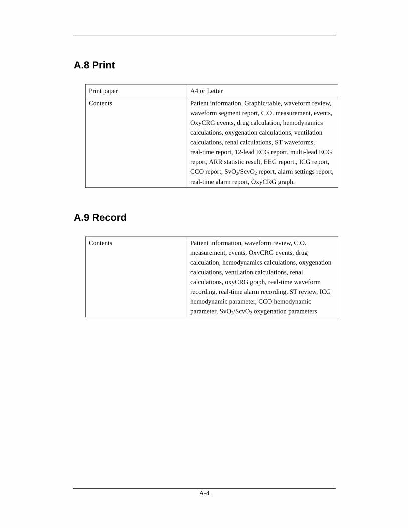
A-4
A.8 Print
Print paper A4 or Letter
Contents Patient information, Graphic/table, waveform review, waveform segment report, C.O. measurement, events, OxyCRG events, drug calculation, hemodynamics calculations, oxygenation calculations, ventilation calculations, renal calculations, ST waveforms, real-time report, 12-lead ECG report, multi-lead ECG report, ARR statistic result, EEG report., ICG report, CCO report, SvO2/ScvO2 report, alarm settings report, real-time alarm report, OxyCRG graph.
A.9 Record
Contents Patient information, waveform review, C.O. measurement, events, OxyCRG events, drug calculation, hemodynamics calculations, oxygenation calculations, ventilation calculations, renal calculations, oxyCRG graph, real-time waveform recording, real-time alarm recording, ST review, ICG hemodynamic parameter, CCO hemodynamic parameter, SvO2/ScvO2 oxygenation parameters

B-1
B Central Monitoring System Alarms The CMS alarms displayed in the system alarm area on the upper screen are shown in the table below.
Alarms Level Cause and solution
Printer is out of toner Low Install the toner. Printer is off line Low Connection between printer and
computer may have problem. Check the connection.
Printer paper is jammed Low Change the paper and then restart the printer and printing task.
Printer is out of paper Low Load paper and then restart the printing task.
Opening Recorder Port Failed Med Restart the recorder. Recorder Paper Jam Low Reload the paper. Recorder Out of Paper Low Reload the paper. Recorder Out of Alignment Low Adjust the recorder head. Recorder is Too Hot Low The recorder has worked for a long
time. Wait until it cools down. Recorder Self-check Error: CPU Med Recorder Self-check Error: RAM
Med
Recorder Self-check Error: ROM
Med
Recorder Self-check Error: WatchDog
Med
Recorder Not Available Med
Restart the recorder.
Recorder S. Communication Error
Med Check the connection cable of recorder serial port.
Network is disconnected. Please check.
High Check the network.
Network is not configured or disabled. Please check.
High Check the network configuration of the CMS.
No bed is online. Please check network connection.
High Check whether the patient monitor has connected to the network.
Database service is abnormal. Please restart CMS or contact the service representative.
High Database service has an error. Restart the CMS to restore database service or contact the service personnel.
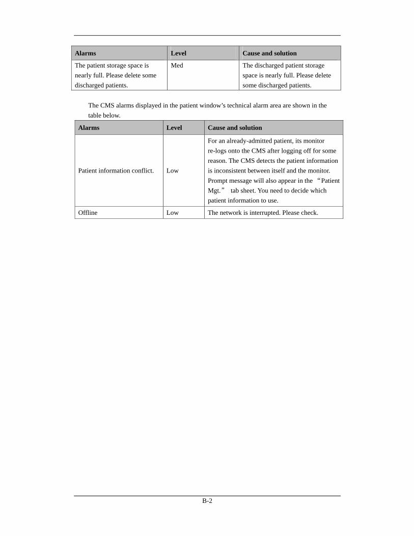
B-2
Alarms Level Cause and solution
The patient storage space is nearly full. Please delete some discharged patients.
Med The discharged patient storage space is nearly full. Please delete some discharged patients.
The CMS alarms displayed in the patient window’s technical alarm area are shown in the table below.
Alarms Level Cause and solution
Patient information conflict. Low
For an already-admitted patient, its monitor re-logs onto the CMS after logging off for some reason. The CMS detects the patient information is inconsistent between itself and the monitor. Prompt message will also appear in the “Patient Mgt.” tab sheet. You need to decide which patient information to use.
Offline Low The network is interrupted. Please check.

C-1
C Units, Symbols, Terms and Formulas
C.1 Units BPM beats per minute
℃ centigrade
cc cubic centimeter
cm centimeter
cmH2O cmH2O
dB decibel
℉ Fahrenheit
g gram
GB giga bytes
GTT gutta
hr hour
hPa hPa
Hz hertz
" inch
k kilo
kg kilogram
kPa kilopascal
l litre
lb pound
m meter, minute
M mega
MB mega bytes
mbar mbar
MHz mega hertz
mcg micrograms
mEq Milli-equivalents
mg milligrams
min minute
ml milliliter
mm millimeters
mmHg millimeters of mercury
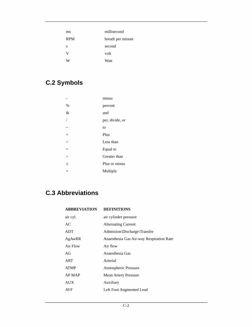
C-2
ms millisecond
RPM breath per minute
s second
V volt
W Watt
C.2 Symbols
- minus
% percent
& and
/ per, divide, or
~ to
+ Plus
< Less than
= Equal to
> Greater than
± Plus or minus
× Multiply
C.3 Abbreviations
ABBREVIATION DEFINITIONS
air cyl. air cylinder pressure
AC Alternating Current
ADT Admission\Discharge\Transfer
AgAwRR Anaesthesia Gas Air-way Respiration Rate
Air Flow Air flow
AG Anaesthesia Gas
ART Arterial
ATMP Atmospheric Pressure
AP MAP Mean Artery Pressure
AUX Auxiliary
AVF Left Foot Augmented Lead
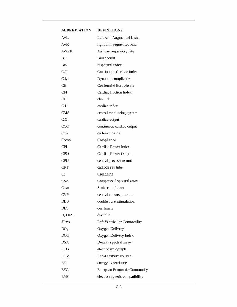
C-3
ABBREVIATION DEFINITIONS
AVL Left Arm Augmented Lead
AVR right arm augmented lead
AWRR Air way respiratory rate
BC Burst count
BIS bispectral index
CCI Continuous Cardiac Index
Cdyn Dynamic compliance
CE Conformité Européenne
CFI Cardiac Fuction Index
CH channel
C.I. cardiac index
CMS central monitoring system
C.O. cardiac output
CCO continuous cardiac output
CO2 carbon dioxide
Compl Compliance
CPI Cardiac Power Index
CPO Cardiac Power Output
CPU central processing unit
CRT cathode ray tube
Cr Creatinine
CSA Compressed spectral array
Cstat Static compliance
CVP central venous pressure
DBS double burst stimulation
DES desflurane
D, DIA diastolic
dPmx Left Ventricular Contractility
DO2 Oxygen Delivery
DO2I Oxygen Delivery Index
DSA Density spectral array
ECG electrocardiograph
EDV End-Diastolic Volume
EE energy expenditure
EEC European Economic Community
EMC electromagnetic compatibility
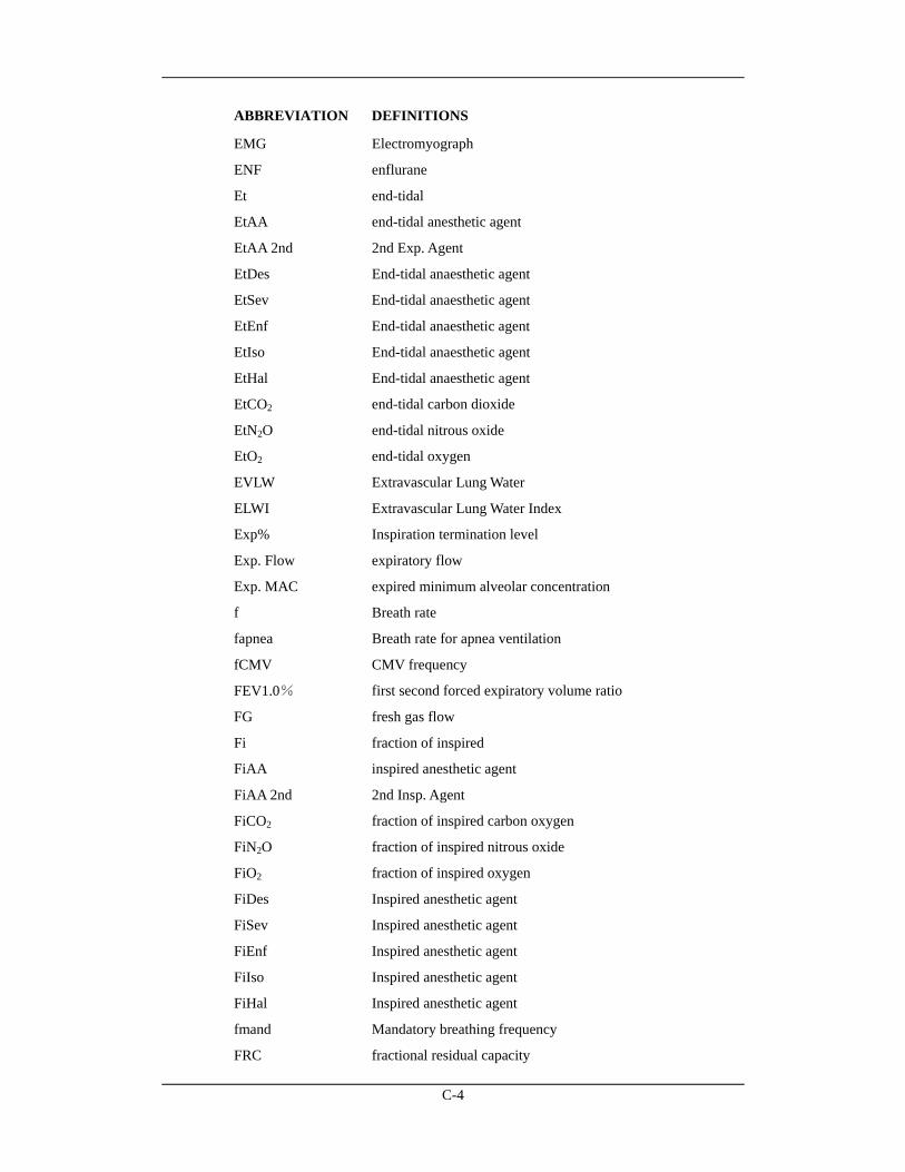
C-4
ABBREVIATION DEFINITIONS
EMG Electromyograph
ENF enflurane
Et end-tidal
EtAA end-tidal anesthetic agent
EtAA 2nd 2nd Exp. Agent
EtDes End-tidal anaesthetic agent
EtSev End-tidal anaesthetic agent
EtEnf End-tidal anaesthetic agent
EtIso End-tidal anaesthetic agent
EtHal End-tidal anaesthetic agent
EtCO2 end-tidal carbon dioxide
EtN2O end-tidal nitrous oxide
EtO2 end-tidal oxygen
EVLW Extravascular Lung Water
ELWI Extravascular Lung Water Index
Exp% Inspiration termination level
Exp. Flow expiratory flow
Exp. MAC expired minimum alveolar concentration
f Breath rate
fapnea Breath rate for apnea ventilation
fCMV CMV frequency
FEV1.0% first second forced expiratory volume ratio
FG fresh gas flow
Fi fraction of inspired
FiAA inspired anesthetic agent
FiAA 2nd 2nd Insp. Agent
FiCO2 fraction of inspired carbon oxygen
FiN2O fraction of inspired nitrous oxide
FiO2 fraction of inspired oxygen
FiDes Inspired anesthetic agent
FiSev Inspired anesthetic agent
FiEnf Inspired anesthetic agent
FiIso Inspired anesthetic agent
FiHal Inspired anesthetic agent
fmand Mandatory breathing frequency
FRC fractional residual capacity
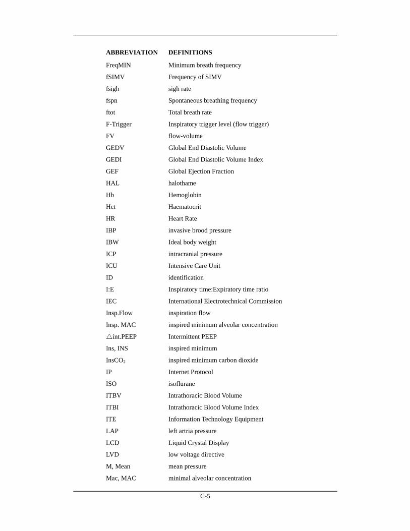
C-5
ABBREVIATION DEFINITIONS
FreqMIN Minimum breath frequency
fSIMV Frequency of SIMV
fsigh sigh rate
fspn Spontaneous breathing frequency
ftot Total breath rate
F-Trigger Inspiratory trigger level (flow trigger)
FV flow-volume
GEDV Global End Diastolic Volume
GEDI Global End Diastolic Volume Index
GEF Global Ejection Fraction
HAL halothame
Hb Hemoglobin
Hct Haematocrit
HR Heart Rate
IBP invasive brood pressure
IBW Ideal body weight
ICP intracranial pressure
ICU Intensive Care Unit
ID identification
I:E Inspiratory time:Expiratory time ratio
IEC International Electrotechnical Commission
Insp.Flow inspiration flow
Insp. MAC inspired minimum alveolar concentration
△int.PEEP Intermittent PEEP
Ins, INS inspired minimum
InsCO2 inspired minimum carbon dioxide
IP Internet Protocol
ISO isoflurane
ITBV Intrathoracic Blood Volume
ITBI Intrathoracic Blood Volume Index
ITE Information Technology Equipment
LAP left artria pressure
LCD Liquid Crystal Display
LVD low voltage directive
M, Mean mean pressure
Mac, MAC minimal alveolar concentration
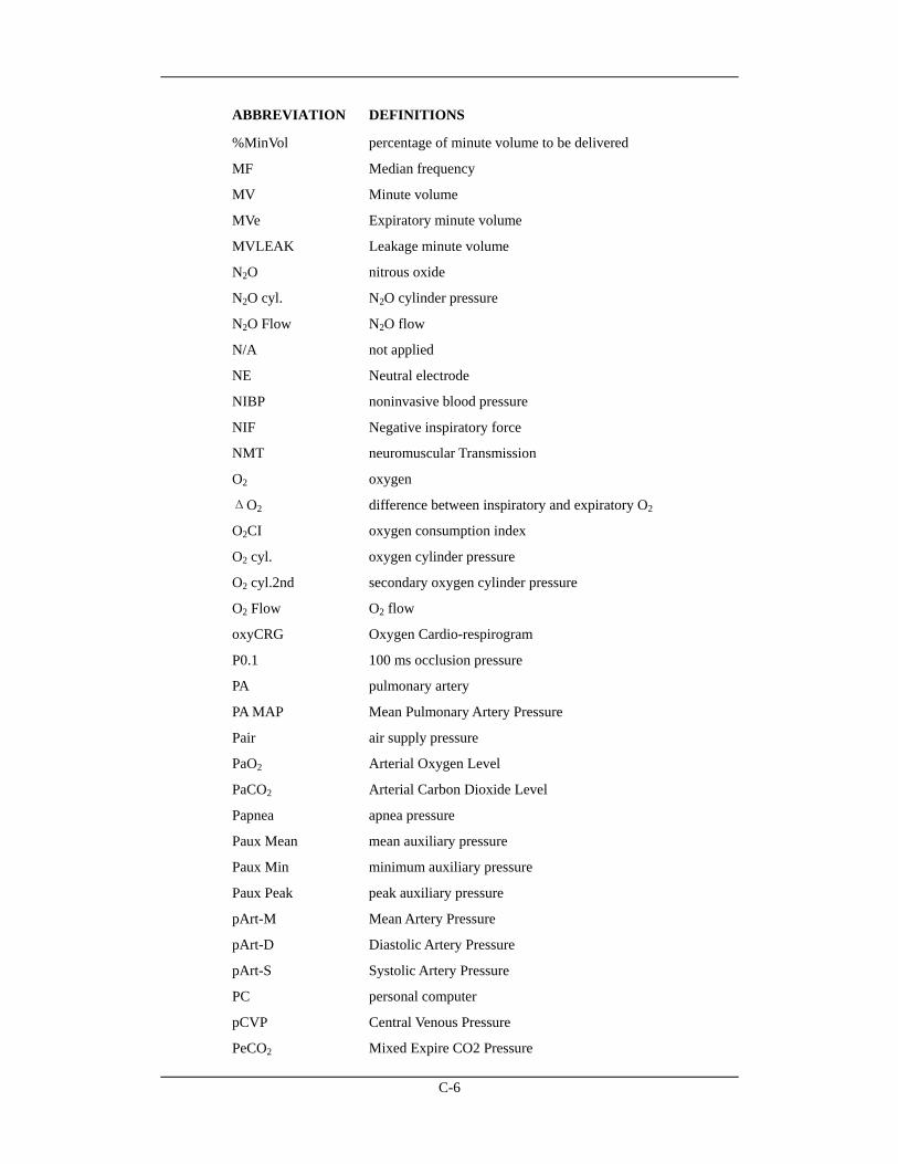
C-6
ABBREVIATION DEFINITIONS
%MinVol percentage of minute volume to be delivered
MF Median frequency
MV Minute volume
MVe Expiratory minute volume
MVLEAK Leakage minute volume
N2O nitrous oxide
N2O cyl. N2O cylinder pressure
N2O Flow N2O flow
N/A not applied
NE Neutral electrode
NIBP noninvasive blood pressure
NIF Negative inspiratory force
NMT neuromuscular Transmission
O2 oxygen
ΔO2 difference between inspiratory and expiratory O2
O2CI oxygen consumption index
O2 cyl. oxygen cylinder pressure
O2 cyl.2nd secondary oxygen cylinder pressure
O2 Flow O2 flow
oxyCRG Oxygen Cardio-respirogram
P0.1 100 ms occlusion pressure
PA pulmonary artery
PA MAP Mean Pulmonary Artery Pressure
Pair air supply pressure
PaO2 Arterial Oxygen Level
PaCO2 Arterial Carbon Dioxide Level
Papnea apnea pressure
Paux Mean mean auxiliary pressure
Paux Min minimum auxiliary pressure
Paux Peak peak auxiliary pressure
pArt-M Mean Artery Pressure
pArt-D Diastolic Artery Pressure
pArt-S Systolic Artery Pressure
PC personal computer
pCVP Central Venous Pressure
PeCO2 Mixed Expire CO2 Pressure
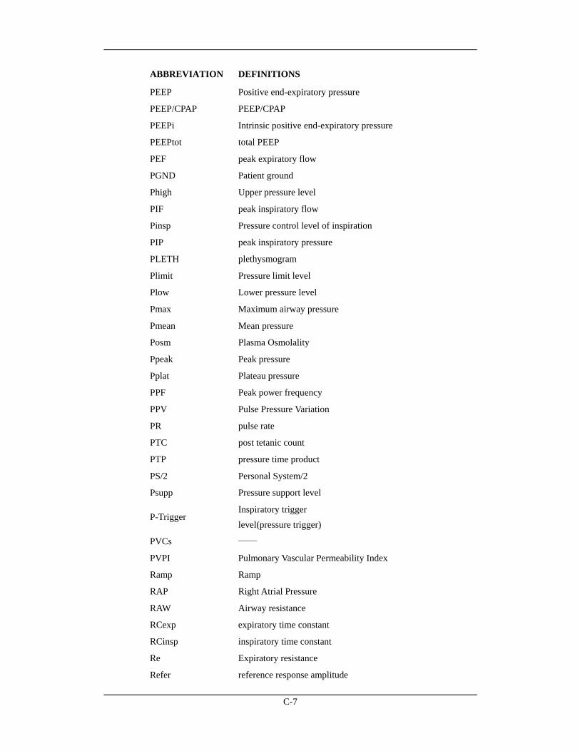
C-7
ABBREVIATION DEFINITIONS
PEEP Positive end-expiratory pressure
PEEP/CPAP PEEP/CPAP
PEEPi Intrinsic positive end-expiratory pressure
PEEPtot total PEEP
PEF peak expiratory flow
PGND Patient ground
Phigh Upper pressure level
PIF peak inspiratory flow
Pinsp Pressure control level of inspiration
PIP peak inspiratory pressure
PLETH plethysmogram
Plimit Pressure limit level
Plow Lower pressure level
Pmax Maximum airway pressure
Pmean Mean pressure
Posm Plasma Osmolality
Ppeak Peak pressure
Pplat Plateau pressure
PPF Peak power frequency
PPV Pulse Pressure Variation
PR pulse rate
PTC post tetanic count
PTP pressure time product
PS/2 Personal System/2
Psupp Pressure support level
P-Trigger Inspiratory trigger level(pressure trigger)
PVCs ——
PVPI Pulmonary Vascular Permeability Index
Ramp Ramp
RAP Right Atrial Pressure
RAW Airway resistance
RCexp expiratory time constant
RCinsp inspiratory time constant
Re Expiratory resistance
Refer reference response amplitude
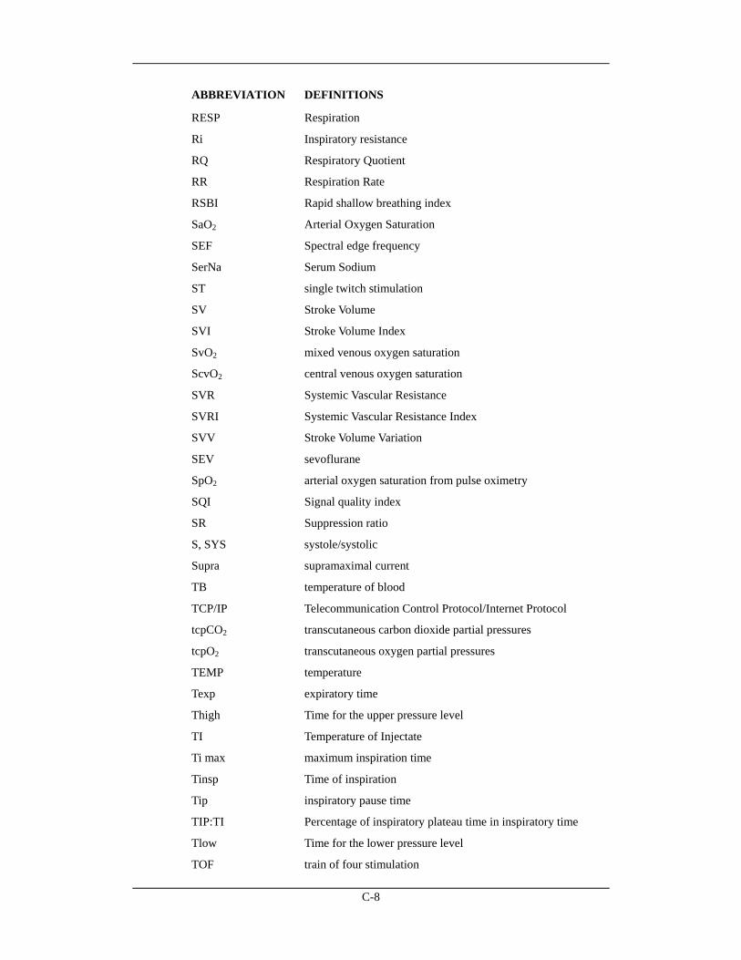
C-8
ABBREVIATION DEFINITIONS
RESP Respiration
Ri Inspiratory resistance
RQ Respiratory Quotient
RR Respiration Rate
RSBI Rapid shallow breathing index
SaO2 Arterial Oxygen Saturation
SEF Spectral edge frequency
SerNa Serum Sodium
ST single twitch stimulation
SV Stroke Volume
SVI Stroke Volume Index
SvO2 mixed venous oxygen saturation
ScvO2 central venous oxygen saturation
SVR Systemic Vascular Resistance
SVRI Systemic Vascular Resistance Index
SVV Stroke Volume Variation
SEV sevoflurane
SpO2 arterial oxygen saturation from pulse oximetry
SQI Signal quality index
SR Suppression ratio
S, SYS systole/systolic
Supra supramaximal current
TB temperature of blood
TCP/IP Telecommunication Control Protocol/Internet Protocol
tcpCO2 transcutaneous carbon dioxide partial pressures
tcpO2 transcutaneous oxygen partial pressures
TEMP temperature
Texp expiratory time
Thigh Time for the upper pressure level
TI Temperature of Injectate
Ti max maximum inspiration time
Tinsp Time of inspiration
Tip inspiratory pause time
TIP:TI Percentage of inspiratory plateau time in inspiratory time
Tlow Time for the lower pressure level
TOF train of four stimulation
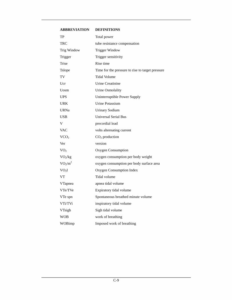
C-9
ABBREVIATION DEFINITIONS
TP Total power
TRC tube resistance compensation
Trig Window Trigger Window
Trigger Trigger sensitivity
Trise Rise time
Tslope Time for the pressure to rise to target pressure
TV Tidal Volume
Ucr Urine Creatinine
Uosm Urine Osmolality
UPS Uninterruptible Power Supply
URK Urine Potassium
URNa Urinary Sodium
USB Universal Serial Bus
V precordial lead
VAC volts alternating current
VCO2 CO2 production
Ver version
VO2 Oxygen Consumption
VO2/kg oxygen consumption per body weight
VO2/m2 oxygen consumption per body surface area
VO2I Oxygen Consumption Index
VT Tidal volume
VTapnea apnea tidal volume
VTe/TVe Expiratory tidal volume
VTe spn Spontaneous breathed minute volume
VTi/TVi inspiratory tidal volume
VTsigh Sigh tidal volume
WOB work of breathing
WOBimp Imposed work of breathing
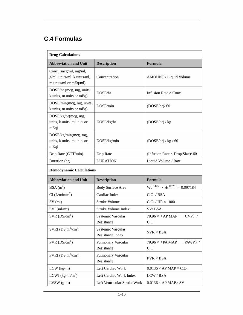
C-10
C.4 Formulas
Drug Calculations
Abbreviation and Unit Description Formula
Conc. (mcg/ml, mg/ml, g/ml, units/ml, k units/ml, m units/ml or mEq/ml)
Concentration AMOUNT / Liquid Volume
DOSE/hr (mcg, mg, units, k units, m units or mEq)
DOSE/hr Infusion Rate × Conc.
DOSE/min(mcg, mg, units, k units, m units or mEq)
DOSE/min (DOSE/hr)/ 60
DOSE/kg/hr(mcg, mg, units, k units, m units or mEq)
DOSE/kg/hr (DOSE/hr) / kg
DOSE/kg/min(mcg, mg, units, k units, m units or mEq)
DOSE/kg/min (DOSE/hr) / kg / 60
Drip Rate (GTT/min) Drip Rate (Infusion Rate × Drop Size)/ 60
Duration (hr) DURATION Liquid Volume / Rate
Hemodynamic Calculations
Abbreviation and Unit Description Formula
BSA (m2) Body Surface Area Wt 0.425 × Ht 0.725 × 0.007184
CI (L/min/m2) Cardiac Index C.O. / BSA
SV (ml) Stroke Volume C.O. / HR × 1000
SVI (ml/m2) Stroke Volume Index SV/ BSA
SVR (DS/cm5) Systemic Vascular Resistance
79.96 ×(AP MAP - CVP)/ C.O.
SVRI (DS m2/cm5) Systemic Vascular Resistance Index
SVR × BSA
PVR (DS/cm5) Pulmonary Vascular Resistance
79.96 ×(PA MAP - PAWP)/ C.O.
PVRI (DS m2/cm5) Pulmonary Vascular Resistance
PVR × BSA
LCW (kg-m) Left Cardiac Work 0.0136 × AP MAP × C.O.
LCWI (kg–m/m2) Left Cardiac Work Index LCW / BSA
LVSW (g-m) Left Ventricular Stroke Work 0.0136 × AP MAP× SV
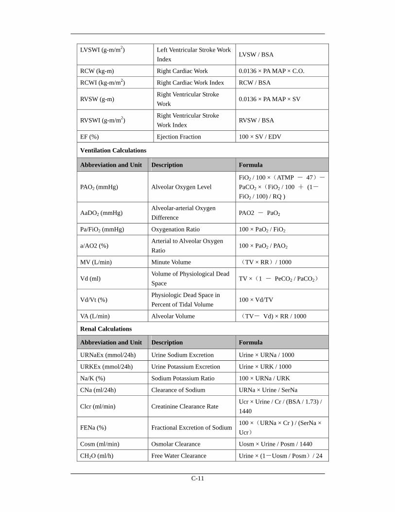
C-11
LVSWI (g-m/m2) Left Ventricular Stroke Work Index
LVSW / BSA
RCW (kg-m) Right Cardiac Work 0.0136 × PA MAP × C.O.
RCWI (kg-m/m2) Right Cardiac Work Index RCW / BSA
RVSW (g-m) Right Ventricular Stroke Work
0.0136 × PA MAP × SV
RVSWI (g-m/m2) Right Ventricular Stroke Work Index
RVSW / BSA
EF (%) Ejection Fraction 100 × SV / EDV
Ventilation Calculations
Abbreviation and Unit Description Formula
PAO2 (mmHg) Alveolar Oxygen Level FiO2 / 100 ×(ATMP - 47)-
PaCO2 ×(FiO2 / 100 + (1-FiO2 / 100) / RQ )
AaDO2 (mmHg) Alveolar-arterial Oxygen Difference
PAO2 - PaO2
Pa/FiO2 (mmHg) Oxygenation Ratio 100 × PaO2 / FiO2
a/AO2 (%) Arterial to Alveolar Oxygen Ratio
100 × PaO2 / PAO2
MV (L/min) Minute Volume (TV × RR)/ 1000
Vd (ml) Volume of Physiological Dead Space
TV ×(1 - PeCO2 / PaCO2)
Vd/Vt (%) Physiologic Dead Space in Percent of Tidal Volume
100 × Vd/TV
VA (L/min) Alveolar Volume (TV- Vd) × RR / 1000
Renal Calculations
Abbreviation and Unit Description Formula
URNaEx (mmol/24h) Urine Sodium Excretion Urine × URNa / 1000
URKEx (mmol/24h) Urine Potassium Excretion Urine × URK / 1000
Na/K (%) Sodium Potassium Ratio 100 × URNa / URK
CNa (ml/24h) Clearance of Sodium URNa × Urine / SerNa
Clcr (ml/min) Creatinine Clearance Rate Ucr × Urine / Cr / (BSA / 1.73) / 1440
FENa (%) Fractional Excretion of Sodium 100 ×(URNa × Cr ) / (SerNa × Ucr)
Cosm (ml/min) Osmolar Clearance Uosm × Urine / Posm / 1440
CH2O (ml/h) Free Water Clearance Urine × (1-Uosm / Posm)/ 24
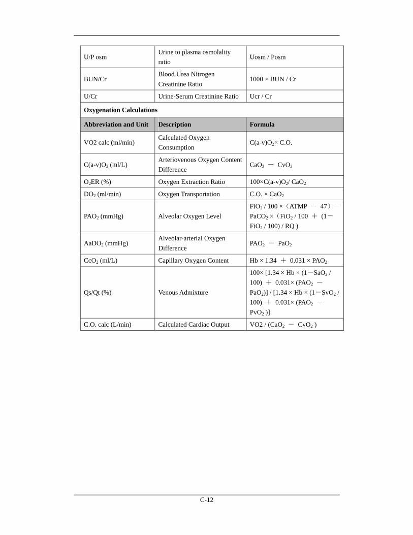
C-12
U/P osm Urine to plasma osmolality ratio
Uosm / Posm
BUN/Cr Blood Urea Nitrogen Creatinine Ratio
1000 × BUN / Cr
U/Cr Urine-Serum Creatinine Ratio Ucr / Cr
Oxygenation Calculations
Abbreviation and Unit Description Formula
VO2 calc (ml/min) Calculated Oxygen Consumption
C(a-v)O2× C.O.
C(a-v)O2 (ml/L) Arteriovenous Oxygen Content Difference
CaO2 - CvO2
O2ER (%) Oxygen Extraction Ratio 100×C(a-v)O2/ CaO2
DO2 (ml/min) Oxygen Transportation C.O. × CaO2
PAO2 (mmHg) Alveolar Oxygen Level FiO2 / 100 ×(ATMP - 47)-
PaCO2 ×(FiO2 / 100 + (1-FiO2 / 100) / RQ )
AaDO2 (mmHg) Alveolar-arterial Oxygen Difference
PAO2 - PaO2
CcO2 (ml/L) Capillary Oxygen Content Hb × 1.34 + 0.031 × PAO2
Qs/Qt (%) Venous Admixture
100× [1.34 × Hb × (1-SaO2 / 100) + 0.031× (PAO2 -PaO2)] / [1.34 × Hb × (1-SvO2 / 100) + 0.031× (PAO2 - PvO2 )]
C.O. calc (L/min) Calculated Cardiac Output VO2 / (CaO2 - CvO2 )


P/N: 046-001291-00(10.0)
Mindray DS USA, Inc.800 MacArthur Blvd.
Mahwah, New Jersey 07430USA
Tel 1.800.288.2121Tel 1.201.995.8000
www.mindray.com
Central Monitoring System
Operator’s Manual