Embed Size (px)
Citation preview

Ope
rato
r's G
uide
© 2013 All rights reserved.
For the most recent version of this manual please visit www.primeralabel.com
LABEL APPLICATORMode Recall/Reset +
-

Notices: The information in this document is subject to change without notice. NO WARRANTY OF ANY KIND IS MADE WITH REGARD TO THIS MATERIAL, INCLUDING, BUT NOT LIMITED TO, THE IMPLIED WARRANTIES OF MERCHANTABILITY AND FITNESS FOR A PARTICULAR PURPOSE. No liability is assumed for errors contained herein or for incidental or consequential damages in connection with the furnishing, performance, or use of this material. This document contains proprietary information that is protected by copyright. All rights are reserved. No part of this document may be photocopied, reproduced, or translated into another language without prior written consent.
Trademark Acknowledgments: Primera is a registered trademark of Primera Technology Inc. Windows is a registered trademark of Microsoft Corporation. All other trademarks are the property of their respective owners.
Printing History Edition 1.1, 101113, Copyright 2013, All rights reserved.
FCC Compliance Statement: This device complies with part 15 of the FCC rules. Operation is subject to the following two conditions: (1) this device may not cause harmful interference, and (2) this device must accept any interference received, including interference that may cause undesired operation.
For Users in the United States: This product is intended to be supplied by a UL listed Direct Plug-In Power Supply marked "Class 2" or a UL listed ITE Power Supply marked "LPS" with output rated 12v, 5 amps or higher. This equipment has been tested and found to comply with the limits for a "Class B" digital device, pursuant to Part 15 of the FCC Rules. In a domestic environment this product may cause radio interference, in which case the user may be required to take adequate measures. This equipment generates, uses, and can radiate radio frequency energy and, if not installed and used in accordance with the instructions, may cause harmful interference to radio communications. However, there is no guarantee that interference will not occur in a particular installation. If this equipment does cause harmful interference to radio or television reception, which can be determined by turning the equipment off and on, the user is encouraged to try to correct the interference by one or more of the following measures:
• Re-orientorrelocatethereceivingantenna.
• Increasetheseparationbetweentheequipmentandreceiver.
• Connecttheequipmentintoanoutletonacircuitdifferentfromthattowhichthereceiverisconnected.
• Consultthedealeroranexperiencedradio/TVtechnicianforhelp.
Use of shielded cables is required to comply with the "Class B" limits of Part 15 of the FCC Rules. You are cautioned that any changes ormodificationsnotexpresslyapprovedinthismanualcouldvoidyourauthoritytooperateand/orobtainwarrantyserviceforthisequipment.
For Users in Canada: Thisdigitalapparatusdoesnotexceedthe"ClassB"limitsforradionoisefordigitalapparatussetoutontheRadio Interference Regulations of the Canadian Department of Communications. Le present appareil numerique n'emet pas de bruits radioelectriquesdepassantleslimitesapplicablesauxappareilsnumeriquesdelaclassBprescritesdansleReglementsurlebrouillage radioelectrique edicte par le ministere des Communications du Canada.

Section 1: Unpacking and Setup ............................................................................................................. 4
Section 2: Loading Label Stock and Arm Adjustment ....................................................................... 5
2.1 Loading Label Stock ................................................................................................................ 5
2.2 Application Arm Height Adjustment ................................................................................. 12
Section 3: Label/Container Settings ..................................................................................................... 13
3.1 Operating Basics .................................................................................................................... 13
3.2 DieCut/Reflective ................................................................................................................. 14
3.3 Application Roller Position .................................................................................................. 15
3.4 Sensor Calibration ................................................................................................................. 15
3.5 Label Position ......................................................................................................................... 16
3.6 Platform Position.................................................................................................................... 16
3.7 Container Guide Adjustment ............................................................................................... 17
3.8 Platform Speed ....................................................................................................................... 18
Section 4: Applying Labels .................................................................................................................... 19
Section 5: Container and Label Specifications .................................................................................. 20
Section 6: Troubleshooting, Maintenance and Other Settings ....................................................... 24
6.1 Troubleshooting ..................................................................................................................... 24
6.2 Maintenance ........................................................................................................................... 25
6.3 Other Settings ......................................................................................................................... 25
6.4 Control Panel Functions ........................................................................................................ 26
6.5 Technical Support................................................................................................................... 26
Section 7: Specifications ......................................................................................................................... 27
Appendix A: Label Path Diagram ......................................................................................................... 28
Appendix B: Control Panel Flowchart ................................................................................................. 29
Index ........................................................................................................................................................... 30
Table of Contents
AP550 Label Applicator 3

4 AP550 Label Applicator
Thank you for purchasing the AP550 Label Applicator (hereafter referred to as "Label Applicator").Boxes,bags,bins,bottles,packages,cansetc.willcollectivelybereferredtoas"containers."
The Label Applicator includes a Power Cord, 12 volt Power Adapter and the parts shown below. TheRollBar,RollGuidesandRollDragArmarelocatedinthesupplyboxalongwiththePowerCord. You will need to assemble them as shown. Attach the Power Cord and switch on the power as shown below. Remove all tape securing parts of the unit.
Place the unit on the back edge of a table at least 30" deep so that the Container Platform does notextendbeyondtheedgeofthetablewhenfullyextended.Thiswillpreventtheplatformfrom accidentally hitting the user during operation.
Section 1: Unpacking and Setup
4 AP550 Label Applicator
LABEL APPLICATORMode Recall/Reset +
-
Roll Bar
Roll Guides
Control Panel
Container Guide
Container Platform
Application Roller
Application Arm
Roll Drag Arm
Power Adapter
Power Input (12v)
Power Cord
Power Switch
Push Bar

Power Cord
AP550 Label Applicator 5
2.1 Loading Label Stock
1. Remove the Roll Bar and Roll Guides from the Label Applicator. The Roll Guides and Roll Drag Arm are removable and adjustable. They are held in place magnetically.
2. Remove one Roll Guide and the Roll Drag Arm from the Roll Bar.
3. Place the label stock roll on the Roll Bar with one side against the upright of the remaining Roll Guide. Place it on the Roll Bar with the loose end of the stock feeding over the top of the roll (labels facing up). The Roll Bar should be oriented with the holes to the rear as shown.
Roll Guides
Roll Drag Arm
Tip! For narrow label rolls you may need to reverse the Roll Guides to allow the uprights to be placed next to the roll. (The bottom of the guides will face away from the roll on each side.)
holes to the rear
labels facing up
Section 2: Loading Label Stock
Roll Bar

4. Place the Roll Drag Arm under the Roll Bar. The Roll Drag Arm may be placed on either side of the Roll Bar but the rounded tip of the Roll Drag Arm should be located inside the core near the center. The arm is spring loaded so that there is downward pressure on the inside of the roll. This helps prevent problems toward the end of a roll.
5. Place the removed Roll Guide back on the Roll Bar and slide it close to, but not pinching the label stock roll.
6. Pullapproximately12"[30cm]oflabelstockoutbeyondthefrontoftheunit.
7. Removeapproximatelythefirst15"[38cm]oflabelsfromtheliner.Thiswillbeimportantlater when you calibrate the label sensor to the label stock.
6 AP550 Label Applicator
Roll Drag Arm
Tip! Roll Guide Uprights must not pinch the label stock roll. (The label stock roll must have free-play between the guides.)
AP550LABEL APPLICATOR
Mode RecallReset + -
15"[38 cm]

AP550 Label Applicator 7
For additional instruction, see the diagram in Appendix A of this manual or the label attached to the left side of the applicator.
8. Push the label stock back until the leading edge of the stock is just before the Label Guide Roller. Push the Guide Collars to the sides so they are out of the label path. These will be adjusted later.
AP550LABEL APPLICATOR
Mode RecallReset +-
Move Guide Collars to the sides.
slack loop behind
Label Guide Roller

9. Usebothindex(pointer)fingerstorolltheleadingedgeofthelabelstockUNDERtheLabelGuide Roller. Feed the stock forward until it enters the Sensor Housing.
Important Note: Do not feed the label stock into upper slot!
8 AP550 Label Applicator
Feed under this plate.
Do NOT feed here!Label Guide Roller
Side View
Sensor HousingLabel Path
Label Guide Roller Label Guide Roller

AP550 Label Applicator 9
10. Continue feeding the stock in the same manner until it protrudes from the front of the unit. Pull the remaining slack through the applicator.
11. Feed the leading edge of the label stock between the Liner Drive and Idler Rollers.
Liner Drive Roller
Liner Idler Roller
Pull remaining slack through.

12. Feed the leading edge of the label stock under the stock coming off the roll. Align the leading edge of the label stock so that it is directly under the stock coming off the roll. Pull it tight.
Note: Make sure the stock is aligned so the labels pass under the line marked on the push bar. The line represents the location of the label sensor. Also, if the label stock has not been used before, make sure the first label does not extend beyond the Liner Drive Roller, as shown.
13. Once the upper and lower label paths are aligned, press up on the middle of the Liner Idler Roller firmly to lock the label stock in place. You will hear a "snap" when it locks into place.
10 AP550 Label Applicator
Liner Drive Roller
Liner Drive Roller
Liner Idler Roller
Lock
Unlock
Align Here
Distance from label stock to arm side plate should be equal in these locations.
Sensor Location Line

AP550 Label Applicator 11
14. Feed any remaining label stock over the Motor Cover, under the label roll and out the back of the applicator.
Important! As you apply the first few labels and more liner becomes available, make sure to route the excess liner off the table and toward the floor. The weight of the liner hanging to the floor will prevent the liner from bunching up and causing problems.
15. Move the Guide Collars so they are close to, but not pinching the label stock.
Motor Cover
Guide Collars

2.2 Application Arm Height Adjustment
The Application Arm basically consists of the upper half of the applicator. This entire assembly can be moved manually to four different positions to accommodate various container heights. Themaximumcontainerheightis8"[20cm].Thereisnominimumheightotherthantheheightrequired to make the container stiff enough for labeling.* To move from one position to another, squeeze the Pin Release Bar to move the pin out of the notch. Move the Application Arm up or down until the pin snaps into the desired notch.
Note: When moving the Application Arm from one position to another, be sure to maintain upward force at the front and rear of the arm. This will prevent the arm from falling when the Pin Release Bar is squeezed and it will allow the arm to move more easily.
* Containerslessthan0.8”[2cm]tallmayrequirearisertoelevatethecontainerabovethebacklip of the platform. This will prevent the forward-moving platform from hitting the Application Arm.
Important! Set the height of the Application Arm as low as possible without causing any part of the arm, other than the Application Roller, to touch the container or platform at any time during the application process. Keep in mind that the Application Roller is pliable and will flex during application.
12 AP550 Label Applicator
Pin Release Bar Pin
Position Container Height
Notch 4 6” - 8” [15-20 cm]
Notch 3 4” - 6” [10-15 cm]
Notch 2 2” - 4” [5-10 cm]
Notch 1 0” - 2” [0-5 cm]
Application Roller and/or label should touch container first.
Container

AP550 Label Applicator 13
Section 3: Label/Container Settings
3.1 Operating Basics
The AP550 has two common modes: Label Application Mode and Setup Mode. In the Label Application Mode, either the current label count or the current memory location is displayed. By default, the current label count is displayed. This allows you to keep track of the number of labelsapplied.Toresetthelabelcounttozero,pressandholdtheRecall/Resetbuttonfortwoseconds. Similarly, press and hold the + or – buttons for two seconds to increase or decrease the label count.
TheAP550hastendifferentmemorylocationstostorevariouslabel/containersettings.Duringuse, the unit must operate in one of ten available memory locations (0-9). The default memory location is “0”, but different memory locations can be used to store different settings for various label/containercombinations.Thisallowsyoutoquicklyswitchbetweencommonjobs.
To display the current memory location, press the Mode button. “F #” will be shown, where “#” is the location number. With the current memory location displayed, you can press the Recall/Resetbuttontoindextoanyoftheotherninememorylocations.PressandholdtheRecall/Resetbuttonfortwosecondstoclearallthesettingsforthememorylocationcurrentlydisplayed. Press the Mode button to return the display to the current label count, otherwise, after four seconds of inactivity the display will automatically revert back to the current label count.
ToaccesstheSetupMode,firstindextothedesiredmemorylocationasdescribedabove.Withthe memory location still displayed, press and hold the Mode button for two seconds. The various settings will now be presented in the order shown in the following table. Press the Recall/Resetbuttontoindexthroughthesettings.Forsomeofthesettings,the+/-buttonswillchangethevalues.PressingtheModebuttonatanytimewillstoretheexistingsetupvaluesand return the unit to the Label Application Mode. See the descriptions on the following pages for more details on each setting.
Note 1: Any changes made in Setup Mode will only apply to the current memory location. The settings in all other memory locations will remain unchanged.
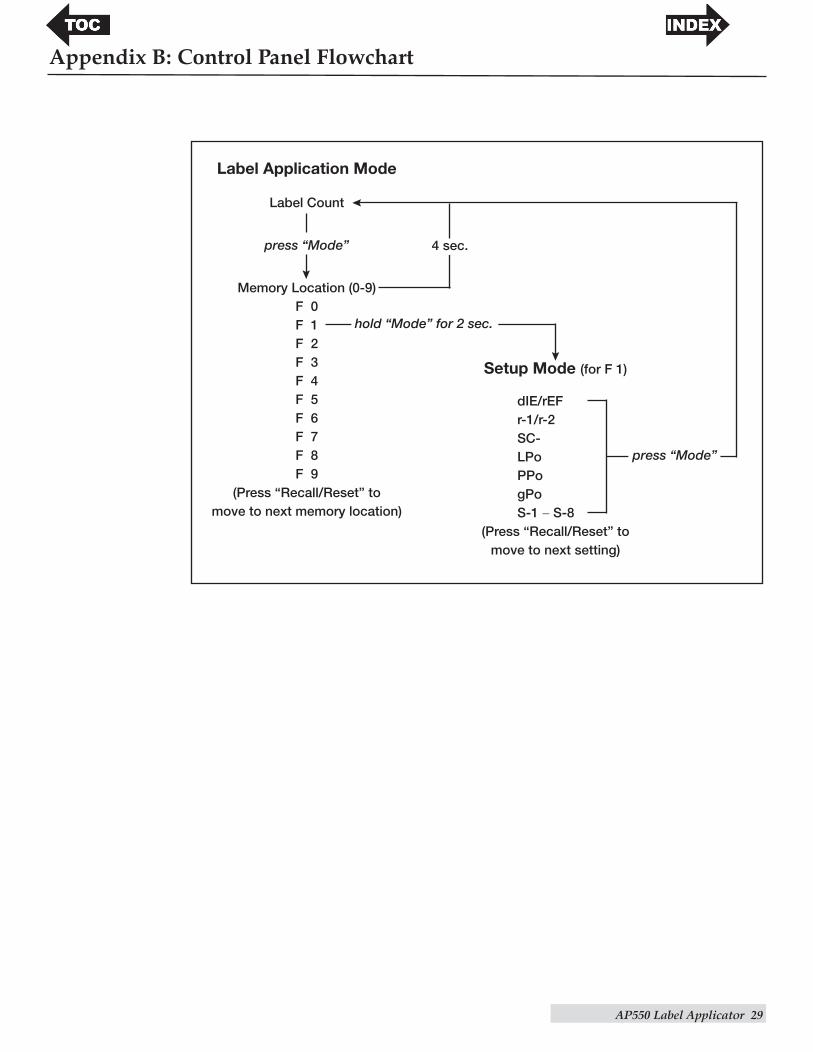
Note 2: See Appendix B for a flowchart of the control panel menu.

14 AP550 Label Applicator
To access the Setup Mode:
Belowisachartdescribingthelabel/containersettings.
Text Displayed Settings Description
dIE/rEF DieCut/Reflective Setsthelabelsensorforgapsensingorblackmark sensing.
r-1/r-2 ApplicationRoller Setto"r-1"forlongerlabels.Setto"r-2"forshorter Position labels.
SC- Sensor Calibration Calibrates the label sensor to the liner material.
LPo Label Position Sets how far the label protrudes from the peel edge.
PPo Platform Position Adjusts the Container Platform start point.
gPo Guide Position Moves platform out for Container Guide adjustment.
S-1 to S-8 Platform Speed Sets the Container Platform return speed between S1 and S8. S1 is slowest. S8 is fastest.
3.2 Die Cut / Reflective
Die Cut (default): If you are using standard die cut labels that look similar to the labels pictured to the right, use this setting regardless of the size of the label. Also use this setting for through-hole label material where a hole is punched through each label or a notch is cut in the side (not common).
Reflective: Use "Reflective" for label material where a black pre-printed line (black mark) on the back of the label stock indicates the break between labels. Black marks are required on clear label stock orwherethelabelwastematrixisleftontheliner.Blackmarkscanalso be used for irregular-shaped labels or on any stock where the print starting position cannot be sensed using the label itself.
ModeRecall/Reset + - Mode
Recall/Reset + -
Die Cut Label Stock
Reflective Label Stock
With label count displayed, press "Mode" once.
Hold "Mode" for 2 seconds.

AP550 Label Applicator 15
3.3 Application Roller Position
r-1: The default Application Roller Position is r-1 which is the position furthest from the peel edge. The r-1 position is the most forgiving for container surfaces that are not completely flat. It also works with the widest variety of container heights.
r-2: The r-2 position should be used if you are using a shorter label that does not reach the ApplicationRollerbeforefallingofftheliner.ThelabelshouldalwaysextendunderneaththeApplication Roller so that the roller will press the leading edge of the label to the container when the arm is lowered.
To adjust the physical position of the Application Roller, remove the thumb screws on either side of the Application Arm. Push or pull the roller to align the thumb screw holes with the desired holes in the side plates. (The r-1 holes are closer to the front of the unit than the r-2 holes.) Replace the thumb screws.
Note: Make sure the physical position of the Application Roller always matches the setting selected.
3.4 Sensor Calibration
The Label Sensor must be calibrated to the specific label stock being used for each memory location.Usethefollowingproceduretocalibratetheapplicatorforyourspecificlabelstock/liner material:
1. Load the label stock as described in Section 2. Be sure to remove labels from the liner back to the Liner Drive Roller. For reflective stock, the black mark should be positioned directly under the Label Guide Roller. The goal is to feed only clean liner through the sensor area. This will give the sensor a good reading of the liner material.
2. Once the liner is loaded, follow the steps above to navigate to the SC- setting in the Setup Mode.
3. Lower the arm to trigger the calibration.
4. The label stock will move forward until the first label is presented for application.
5. Calibration for this liner is now complete and the values are stored in the current memory location.
Note: It is not necessary to recalibrate the label sensor between rolls of the same label stock.
LABEL APPLICATORMode Recall/Reset +
-
Thumb Screw
Application Roller
Thumb Screw
Liner Drive Roller
For reflective stock, the black mark should be positioned directly under this guide roller.
Remove labels from liner to this point.

16 AP550 Label Applicator
3.5 Label Position
Thissettingwilladjustthedistancethelabelstockextendspastthepeeledge.Youmayadjustthissetting+/–0.32”[8.1mm].Usethe+/–buttonstoadjusttheposition.Press"Recall/Reset"to store the position in the current memory location. Depending on your container and the angle of the Application Arm, you may change this setting to achieve a more consistent label position on the container.
Note: For some thinner label stock, if the Label Position is increased too much, the label could fold or wrinkle at the leading edge.
3.6 Platform Position
The location of the label applied to the container in the direction of Container Platform movement can be adjusted by changing the start position of the platform. To determine the correct Container Platform start position:
1. Place your container on the platform, push the container back until it touches the back edge of the platform.
2.50" Start Position
6" Container
Container Platform
Leading Edge of Label
Application Roller
Label
Label Position [distance from peel edge]Peel Edge

AP550 Label Applicator 17
2. Atthe"PlatformPosition"[PPo]setupoption,pressthe+/–buttonstoadjustthestartingContainerPlatformpositionin0.01”[0.25mm]increments.Pressandholdthe+/–buttonstoquicklyadjusttheposition.Thetraywillmoveasyoupressthe+/–buttons.Oncethecontainer is near the leading edge of the label stock, push down on the Application Arm to visually verify the correct position. In this mode the label will not apply. Readjust as necessary. The default position of the platform is 0.0” and will place the leading edge of thelabelabout8.0to9.0"[20to23cm]fromthebackofthecontainer.Ifyouareapplyingalabeltothefrontedgeofa6”container,forexample,yourplatformpositionshouldbeapproximately2.5”(8.5”minuscontainerheight=PPosetting).Press"Mode"or"Recall/Reset" to store this value in the current memory location.
3.7 Container Guide Adjustment
The Container Guide can be used to quickly and consistently positioncontainersontheplatform.Thehorizontal[side-to-side]location of an applied label on a container is determined by the horizontal position of the label stock in the Applicator Arm and the positionoftheContainerGuide.Atthe"GuidePosition"[gPo]setting,theplatformwillfullyextendsoyoucanaccesstheContainer Guide Thumb Screw on the underside of the platform. Loosen the Thumb Screw and move the guide to the appropriate position so that the container is in position to receive the label at the desired location. Retighten the Thumb Screw.
Caution: Stand clear of the front of the unit to avoid being hit by the platform as it extends.
Note 1: The platform can also be fully extended outside of the Setup Mode by pressing "Recall/Reset" and "-" simultaneously. Press the Mode button to reset the platform.
Note 2: You may also remove the Container Guide if your container is wider than the platform.
Note 3: You may also install an additional Container Guide to hold containers more securely.
Note 4: The Primera Container Holding Kits can be used to hold odd-shaped containers or any smaller container in place. They are Primera part numbers 074398 and 074399.
ModeRecall/Reset + -
LABEL APPLICATORMode Recall/Reset +
-
Container Guide

18 AP550 Label Applicator
3.8 Platform Speed
The Platform Speed setting controls the speed of the platform when it returns to the start position.S-1istheslowestspeed.S-8isthefastest.Press"+/–"toselectthedesiredspeed.Press"Recall/Reset"tostorethesettinginthecurrentmemorylocation.Fasterspeedswillallowtheplatformtogetintopositionforthenextcontainermorequickly.However,fasterplatformspeeds may cause the platform to stall with heavier containers.
After completing the setup options you are now ready to start labeling your containers. The applicator accepts many types of flat or tapered containers. Please see Section 5 for complete container specifications.
LABEL APPLICATORMode Recall/Reset +
-
Height
Width
Length

AP550 Label Applicator 19
1. Press the Mode button to display the current memory location.
2. Ifneeded,presstheRecall/Resetbuttontoindextothedesiredmemorylocation.
3. Assuming the desired label stock is loaded (see Section 2), place a container on the platform. Hold the container biased against the back edge of the platform and Container Guide until labeling begins.
4. Lower the Application Arm quickly until it touches the container. The platform and container will move toward you as the label is pulled from the liner at the peel edge. This motion will apply the label. Maintain downward force on the arm until the label is completely applied.
Note: If you stop or delay when bringing the arm toward the container, the label could be ejected before the arm reaches the container. Excessive force may cause the platform to stall.
6. Lift the Application Arm to return the platform to its starting position.
7. Remove the container and repeat the process.
The display will automatically indicate the number of labels applied. To reset the counter, press andholdtheRecall/Resetbuttonfortwoseconds.
Section 4: Applying Labels
LABEL APPLICATORMode Recall/Reset +
-
Push here

20 AP550 Label Applicator
These specifications are provided for preliminary compatibility purposes only! Any questionable container/label combinations should always be tested by Primera Technical Support!
Container Specifications:
Length 0.75”–12.2”[19mm–310mm](onplatform) 12.2"[310mm]–18”[457mm](overhangingplatform) 18”[457mm]orgreaterwithexternalsupportofhandorothermechanismthat allows the platform to move
Width 0.75”–12”[19mm–305mm](onplatform) 12"[305mm]–18”[457mm](overhangingonesideofplatform) 18”[457mm]orgreater(overhangingoneorbothsidesofplatform*subjecttoweight restrictionsbelowandexternalsupport,ifneeded.)
Height 0.8”–8”[20mm–203mm]**
Weight 20lbs.[9.1kg]***
Shape Flat, tapered front-to-back, flat front with rounded edges, cube, cuboid, cylinder on end, prism on end
Type Taperedbottles,boxes,packages,bags,pouches,lids(canning-jarlids,jelly-jarlids, any flat lid), tins, bins, packages, cans, and many more.
*ContainermayextendoverbothsidesofplatformifContainerGuideisremoved.
**Flatcontainers/bagscanbelabeledifa0.8”[2cm]riserisusedtoraisethelevelofthecontainersotheApplicationArmdoesnotinterferewiththefixedmetalguideonthebackofthe platform. The riser can be made from wood or any other solid material and secured to the platform if desired.
***Thisisarecommendedmaximumbasedona20lbs.[91kg]containercenteredontheplatform.Heaviercontainersand/orcontainersbiasedtotheedgesof the platform may work, but may shorten the life of the platform bearings.
Label Placement (Application Area)
Labelsmaybeplacedwithintheback8"[20cm] ofanycontainer.Forexample,an18”longcontainer that overhangs the front of the Container Platform can only have a label applied within the back 8” of that container which would result in a label that is not centered on the container.
Section 5: Container and Label Specifications
LABEL APPLICATORMode Recall/Reset +
-
Height
Width Length
Application Area
8"

AP550 Label Applicator 21
Label and Roll Specifications
A wide variety of label stock can be used in the Applicator. Refer to the following specifications and settings before ordering custom stock from Primera or any stock from another company.
Important! Test all custom made label stock with the intended applicator before ordering large quantities!
Label Width
Liner Width
Black Mark Width
Gap Between Labels
Label Height
Distance from edge of Media
Label Sensing Methods
Method 1: Label Gap Sensing
Method 2: Reflective/BlackMark Sensing(Black Mark must be printedon back side of label stock)
Note: See table below for Max and Min values in inches and millimeters.

22 AP550 Label Applicator
Max Min
LabelWidth 4.0"[101.6mm] 0.75"[19mm]
Liner/MediaWidth 4.125"[104.8mm] 0.875"[22.2mm]
LabelHeight/Length 6.0"[152.4mm] 0.75"[19mm]
GapBetweenLabels 10"[253mm] 0.1[2.5mm]
Reflective/BlackMarkWidth* N/A 0.1"[2.5mm]
MaxOuterDiameter(OD) 8.0"[203.2mm] N/A
InnerCoreDiameter(ID) 3.0"[76.2mm]*** 2.0"[50.8mm]
TotalThickness 0.010”[10mil] N/A (Liner + Label)**
*TheReflective/BlackMarkshouldbeopaquetoinfraredlight.Themarkshouldbebetweenthe labels. The end of the mark should correspond with the beginning of the label.
**Thisistherecommendedmaximum.Therearetwofactorsthatdeterminewhethertheapplicator will accept any particular stock thickness:
1. The ability for the applicator to pull the paper through the drive rollers.
2. The ability for the sensor to read through the backing if the sensor is set to "Die Cut".
If you are using reflective label-sensing mode, number 2 does not apply. The fact that the sensor must read through the backing in die cut mode will limit the thickness much more than the applicators ability to pull the paper through the drive rollers. However, if you adjust the opacity level of the liner enough to allow the label to be seen by the stock sensor, the thickness will only be limited by the applicators ability to pull it through the drive rollers. For these reasons the weight or thickness of the liner is a variable that cannot easily be defined. Primera recommends and uses 40# liner with all label stock. It is important to test all label stock with the intended applicator before ordering large quantities!
*** Inner core diameter can be greater than 3.0". However, as the inner core diameter increases beyond 3.0" the acceptable outer diameter decreases. If there is any doubt, contact Technical Support to test the label stock.
Roll Specifications
Label Side Out
Core I.D.
Core O.D.
Roll O.D.
up to 8”
Label Stock
2”-3”

AP550 Label Applicator 23
Label Copy Position Chart
Copy positions 1-4 (labels wound out) - compatible with the AP550
1. Top of copy dispenses first.
2. Bottom of copy dispenses first.
3. Right side of copy dispenses first.
4. Left side of copy dispenses first.
Copy positions 5-8 (labels wound in) - NOT compatible with the AP550
5. Top of copy dispenses first.
6. Bottom of copy dispenses first.
7. Right side of copy dispenses first.
8. Left side of copy dispenses first.
YPOCYPOC
YPOCYPOC
YPOC
YPOC
YPOCYPO
C
YPOCYPO
C
YPOC
POC YPOC
POC
YPOCYPOCYPOCYPOC
YPOC YPOC
YPOC
YPOC
YPOCYPOC

24 AP550 Label Applicator
6.1 Troubleshooting
Multiple labels feed from the Application Arm, with or without platform movement.
Calibrate the label sensor. (See Section 3.4.)
Display flashes "SC-" when I try to apply a label.
Calibrate the label sensor. (See Section 3.4.)
Labels are applied to the container crooked.
1. Check for container taper. Some containers may have a slight taper that will cause the label to be applied crooked. Make sure your container is oriented so the taper is from front-to-back or back-to-front, NOT side-to-side. You may also choose to install a wedge on one side or the other to make the container level from side-to-side.
2. Roll Guides should also be positioned very close to the roll, but not squeezing any part of it (so the roll has very little, but at least some side-to-side play between the guides). For larger, heavier rolls make sure that the roll is positioned on top of the Roll Guides with the magnetic portions facing in. This will minimize the chances that the heavy roll will push the guides out of place.
3. Make sure the Roll Drag Arm is in place as described in Section 2.1.4.
4. Make sure the label stock runs parallel to the Application Arm. (See Section 2.1.12.)
Label position on container varies, side to side, from container to container.
Make sure the label stock is running parallel to the Application Arm (See Section 2.1.12.) and the Roll Guides and Guide Collars are close to, but not pinching the label stock. Make sure the thumb screw holding the Container Guide in place is tight. Also, be sure to hold the container tight to the guide until labeling begins.
Label position on container varies, top-to-bottom, from container to container.
Lower the Application Arm height. (See Section 2.2.) Change the Application Roller Position and/orthelabeldistancefromthepeeledge.(SeeSection3.3&3.5.)Theoptimalroller/labelposition is determined by the angle of the arm during application and the various properties of a particularlabel/containercombination.Experimentationmaybenecessary.
Leading edge of labels fold as they are applied to the container.
Decrease the label distance from the peel edge. Some thin polyester and polypropylene label materials do not have enough stiffness and can droop down from the peel edge if the label position is set too high. This can cause folding at the leading edge of the label. (See Section 3.3&3.5.)
There are bubbles or wrinkles in the label.
Wrinkles or bubbles can appear on the applied label if the container is not smooth or has bumps orridges.Tominimizebubblingorwrinkling,adjusttheApplicationRollerpositionand/ortheLabel Position. (See Section 3.5.)
Container Platform is stalling, scraping, or squealing.
AnApplicationArmpositionthatistooloworexcesspressureontheApplicationArmPushBarcancausetheplatformtostall.RollGuidesand/orGuideCollarsthatpinchthelabelstockcan also contribute to stalling. After checking and correcting these items, if the platform still stalls or if scraping or squealing is detected, replace the Platform Bearing Plate. (See Section 6.2.)
Section 6: Troubleshooting, Maintenance and Other Settings

AP550 Label Applicator 25
6.2 Maintenance
Liner Rollers
When not in use, leave the Liner Idler Roller in the unclamped position. This will minimize the possibility that permanent indentations will be made in the Liner Drive Roller. If any label jams occur,besuretoremoveanylabelsand/oradhesivefrombothoftheserollers.
Lubricating bearings
Primera recommends oiling the four bearings associated with the Liner Drive Roller and Liner Idler Roller. Oil these four bearings once every 50,000 containers labeled. They should only be oiled after the first 50,000 containers as they are lubricated with a special grease at the factory. One drop of any machine oil or motor oil for each bearings should be adequate. This maintenance is optional but will increase the life of the applicators for heavy users who use the applicator for several hours each day.
Replacing the Platform Bearing Plates
The Platform Bearing Plates ride against the Platform Shafts and are subject to wear. They will likely last from 100,000 containers to 1,000,000 containers depending on the weight of the containers used. As they wear, eventually the front of the Container Platform will ride low enough to scrape against the Base Plate. At that point, the parts would need to be replaced. Theyaremountedbytwoscrewsthatcanbeaccessedwiththeplatformextended.
Platform Bearing Plate: Primera Part # 691306
6.3 Other Settings
Setting the LED display intensity
1) Press and hold the Mode and + button until the display shows “LEd”.
2) Then press the + or – buttons to adjust the LED intensity.
3) Press the Mode button to accept.
Moving tray to "out" position
PressandholdtheRecall/Resetand–buttonsimultaneously.Thetraywillmovetothe"out"position.
Setting English or metric units
English
1) Turn off the unit.
2) Press and hold the Mode button and the + button simultaneously while switching on the unit.
Upon start up, the first digit will display as a "–" followed by the current firmware version.
Metric
1) Turn off the unit.
2) Press and hold the Mode button and the – button simultaneously while switching on the unit.
Upon start up, the first digit will display the upper and lower segment followed by the current firmware version.
ModeRecall/Reset + -
ModeRecall/Reset + -
English
Metric
26 AP550 Label Applicator
Test Mode
1) Turn off the unit.
2)PressandholdtheRecall/Resetand+buttonwhileswitchingontheunit.
3)The unit will now move the platform in and out and run the liner drive roller continuously.
Note: Be sure to unload any label stock from the Liner Drive Roller before starting the Test Mode.
Turning Test Mode off
1) Turn off the unit.
2)PressandholdtheRecall/Resetand–buttonwhileswitchingontheunit.
Test Mode will be disabled.
6.4 Control Panel Functions
Mode Button: Toggles the display between the label count and the current memory location. Hold for two seconds to enter the Setup Mode for the currently displayed memory location. PresstoexittheSetupMode.
Recall/Reset Button:DisplaysnextmemorylocationinMemoryMode.Indexestothenextparameter in Setup Mode. Hold for two seconds to reset the label counter when in Label Count Mode. Hold for two seconds to clear all the settings for the current memory location.
+ Button: Increments the current parameter when in Setup Mode. Hold to advance more quickly. When the label count is displayed, hold for two seconds to increase the count.
– Button: Decrements the current parameter when in Setup Mode. Hold to advance more quickly. When the label count is displayed, hold for two seconds to decrease the count.
6.5 Technical Support
If you have difficulties operating your applicator, the procedures in this manual and the software User's Guide should, in most cases, solve the problem. If you still have difficulty, contact Primera Technical Support using one of the methods listed below.
Source Location
PrimeraKnowledgeBase www.primera.com/knowledgebase.html
EmailSupport www.primera.com/contact_tech_support.cfm
Phone Support 763-475-6669 (Mon - Fri 8 a.m. - 6 p.m. CST)

AP550 Label Applicator 27
ContainerPlatform 12”Wx12.2”D[305x310mm]*
ContainerHeight .002”-8”[0.05mm-203mm]**
Container Shape Flat, tapered front-to-back, flat front with rounded edges, cube, cuboid, cylinder on end, prism on end
LabelWidth 0.75”-4”[19mm-101.6mm]
LabelHeight 0.75”-6”[19mm-152.4mm]
LabelLinerWidth 0.875”-4.125”[22.2mm-104.8mm]
LabelPlacement Leadingedgeupto8”[203mm]fromtrailingcontaineredge
LabelRollDiameter 8”[203mm](maximum)
LabelRollCore 2”-3”ID[50.8mm-76.2mm]
ElectricalRating 12VDC,5.0A
PowerRequirements 100-240VAC,50/60Hz,1.7A
Agency Certifications UL, UL-C, CE, FCC Class B
Weight 24lbs[10.9kg]
Dimensions 12”Wx21.3”Dx10.1”–15.4”H[305x541x256–391mm]
*Containermayoverhangplatformtothefrontand/oreitherside.
**Containersshorterthan0.8”[20.3mm]mayrequireadaptivespacers.Someveryshortcontainers may not be stiff enough to support label application.
Section 7: Specifications

28 AP550 Label Applicator
Line
r Driv
e R
olle
r
Labe
l Pat
h D
iagr
am Labe
l Gui
de R
olle
r
App
licat
ion
Rol
ler
Peel
Edg
eLi
ner I
dler
Rol
ler
Labe
l Pat
h
Appendix A: Label Path Diagram
AP550 Label Applicator 29
Appendix B: Control Panel Flowchart
Label Application Mode
Label Count
press “Mode”
Memory Location (0-9)F 0F 1F 2F 3F 4F 5F 6F 7F 8F 9
(Press “Recall/Reset” to move to next memory location)
Setup Mode (for F 1)
dIE/rEFr-1/r-2SC-LPoPPogPoS-1 − S-8
(Press “Recall/Reset” to move to next setting)
4 sec.
hold “Mode” for 2 sec.
press “Mode”

30 AP550 Label Applicator
Index
Application Roller ............................................................................................................................. 12, 15
Container Guide ...................................................................................................................................... 17
dIE (Control Panel Display) .................................................................................................................. 14
Die Cut ...................................................................................................................................................... 14
English ...................................................................................................................................................... 25
gPo (Control Panel Display) .................................................................................................................. 14
Label Position ........................................................................................................................................... 16
LPo (Control Panel Display) .................................................................................................................. 14
Memory Location .................................................................................................................................... 13
Metric ........................................................................................................................................................ 25
Platform Position ..................................................................................................................................... 16
Platform Speed ........................................................................................................................................ 18
PPo (Control Panel Display) .................................................................................................................. 14
r-1 (Control Panel Display) .................................................................................................................... 14
r-2 (Control Panel Display) .................................................................................................................... 14
rEF (Control Panel Display) .................................................................................................................. 14
Reflective .................................................................................................................................................. 14
Roller Position .......................................................................................................................................... 15
SC- (Control Panel Display) .................................................................................................................. 14
Test Mode ................................................................................................................................................. 26
Thumb Screw ..................................................................................................................................... 15, 17
Sensor Calibration ................................................................................................................................... 15

P/N511371-101113