Embed Size (px)
Citation preview

OPERATORS INSTRUCTION MANUAL
COMPLETE WITH PARTS LIST & DRAWING
MOTOR: R1511 / R1521 / R1522 DRILL STAND: TS-132 / TS-162 / TS-132(AB52) / TS-162(AB52)
EXTENSION COLUMN CARRY CASE VERSION
WARNING!! Be sure to read and understand this manual thoroughly before starting operation. Save this manual carefully for future reference.
SHIBUYA COMPANY,LTD
5-86 MOKUZAIKO-KITA, HATSUKAICHI HIROSHIMA 738-0021
JAPAN TEL: +81-829-34-4510
Distributed by
For Parts and Service Call
Toll Free: 1-866-688-1032
Tel: 816-246-5515
www.diteq.com
U.S. Revision Date Aug. 2012 AC110-120V, U US

1
IMPORTANT NOTICE
IMPORTANT NOTICE
WARNING!! Improper use of the equipment and machine may cause serious or fatal injury. Read, understand and follow carefully the operating and safety instructions in this manual before using the core drilling equipment.
WARNING!! This machine is for core drilling. Never use it for any other purpose. This machine is to be used with a drill stand. Do not use it for hand-held drilling for safety purpose.
WARNING!! Copyright reserved on this manual. Publication on the technical information and drawings in this manual, and duplication without prior permission of Shibuya Company, Ltd. is prohibited.
LIMITED WARRANTY
LIMITED WARRANTY Every Shibuya Core Drilling Machine is thoroughly inspected and tested before leaving the factory. Should any trouble develop, return the complete machine prepaid to your nearest Shibuya authorized dealer. If inspection shows the trouble is caused by defective workmanship or material, all repairs will be made without charge and the machine will be returned. This warranty does not apply where; (1) Repairs or attempted repairs have been made by persons other than Shibuya’s authorized dealer. (2) Repairs are required because of normal wear. (3) The machine has been misused or involved in an accident. (4) Misuse is evident such as caused by overloading the Machine beyond its rated capacity. (5) The machine has been used after partial failure or normal wear. (6) The machine has been used with improper accessory. (7) The machine expires its warranty period of 1 year upon receipt of the machine. No other warranty, written or verbal is authorized.

2
OBJECT OF THIS MANUAL AND ITS OUTLINE The object of this manual is to provide the detailed necessary information, in order to operate the machine in proper way. This manual includes the following information. 1. SAFETY Be sure to read this chapter before starting operation. In this chapter, the meanings of symbol marks for safety, and the safety precautions that must be obeyed to are explained. 2. GENERAL DESCRIPTION & SPECIFICATIONS In this chapter, the purpose of this machine, name of the parts, specifications, and contents of standard accessories such as Tool-Kit are explained. 3. UNPACKING AND ASSEMBLY In this chapter, how to assemble the machines after unpacked is explained. 4. GROUNDING INSTRUCTION In this chapter, how to make a proper grounding and choice of proper plugs are explained. 5. RESIDUAL CURRENT DEVICE In this chapter, the recommendation for a use of residual current device of optional item is explained. 6. FEATURES OF THIS MACHINE In this chapter, this machine’s unique features are explained. 7. HOW TO OPERATE THIS MACHINE In this chapter, how to operate the machine and how to quit the operation are explained. 8. OPTIONAL ITEMS 9. MAINTENANCE In this chapter, how to make a proper maintenance of the machine and how to adjust the machine are explained. 10. CLEANING In this chapter, cautions at cleaning are explained. 11. DAILY INSPECTION In this chapter, what should be inspected before starting the operation is explained. 12. TROUBLESHOOTING In this chapter, what countermeasures you should take are explained for any troubles you may encounter. 13. SCHEMATIC DRAWINGS WITH SPARE PARTS LISTS
3
INDEX IMPORTANT NOTICE 1 LIMITED WARRANTY 1 OBJECT OF THIS MANUAL AND ITS OUTLINE 2 INDEX 2 1.0 SAFETY 3 1.1 THE MEANING OF THE SYMBOL MARKS 3 1.2 SAFETY PRECAUTIONS 3-4 1.3 IMPORTANT OPERATING INSTRUCTIONS 5 2.0 GENERAL DESCRIPTION & SPECIFICATIONS 6 2.1 GENERAL DESCRIPTION 6 2.2 SPECIFICATIONS 6 2.3 STANDARD ACCESSORIES 6 3.0 UNPACKING AND ASSEMBLY 7 4.0 GROUNDING INSTRUCTION 7 5.0 RESIDUAL CURRENT DEVICE (RCD) 7 6.0 FEATURE OF THIS MACHINE 8 7.0 HOW TO OPERATE THIS MACHINE 8 7.1 INSTALLATION 8 7.2 ATTACH CORE BIT 9 7.3 CHOOSE PROPER REVOLUTION SPEED 9 7.4 HOW TO SHIFT THE GEAR 9 7.5 PREPARATION FOR WATER SUPPLY 9 7.6 PRECAUTION BEFORE OPERATION 10 7.7 OPERATING PROCEDURE 10-12 8.0 OPTIONAL ITEMS 12 9.0 MAINTENANCE 13 9.1 ADJUSTMENT OF CARRIAGE BLOCK 13 9.2 REPLACEMENT OF CONSUMPTION PARTS 13 9.3 REPLACEMENT OF ROLLERS INSIDE CARRIAGE BLOCK 13-14 9.4 REPLACEMENT OF SLIDING PLATE INSIDE CARRIAGE BLOCK 14 9.5 REPLACEMENT OF CARBON BRUSHES 14 9.6 REPLACEMENT OF OIL SEAL 15 9.7 REPLACEMENT OF O-RING 15 9.8 REPLACEMENT OF SEAL RING 15 9.9 LUBRICATION 15 10.0 CLEANING 15 11.0 DAILY INSPECTION 16 11.1 OTHER INSPECTION 16 12.0 TROUBLESHOOTING 17 13.0 SCHEMATIC DRAWINGS WITH SPARE PARTS LISTS 18-27

4
SAFETY 1.0 SAFETY The safety precautions that must be obeyed are explained in this chapter.
WARNING!! Be sure to obey the instructions written in this manual, when you operate the machine. If you have any questions, please feel free to contact Shibuya’s authorized dealers.
1.1 THE MEANING OF THE SYMBOL MARKS In this manual, warning signs are classified into four levels based on the level of potential risks. DANGER!!! : This mark indicates the imminent risks that lead to death or serious injury for the operators and
others, unless the safety instruction is observed. WARNING!! : This mark indicates the potential risks that may lead to death or serious injury for the
operators and others, unless the safety instruction is observed. CAUTION! : This mark indicates the potential risks that lead to injury for the operators and others, unless
the safety instruction is observed. NOTE: This mark is used for the information that is necessary for you to know. SAFETY 1.2 SAFETY PRECAUTIONS
DANGER!!!
The following instructions are essential safety measures that you must take. Unless observed, improper way of use leads to death or serious injury of yourselves or others.
[1] Know your machine. Read this manual carefully to learn the application of the machine and the limitations as
well as potential hazards associated with the machine. [2] During the operation, the Core-Bit rotates with very high speed. Do not wear loose clothing, dangling objects,
rings, and jewelry to eliminate the risk in which the operator gets caught in the moving parts such as the Core-Bit. Keep your face away from the air inlet, outlet of the motor. Long hair must be tied up.
[3] Always wear protective clothing such as helmets, safety goggles, earplugs, heavy-duty gloves, and special
work boots with reinforced toe. (During the operation, do not wear gloves to reduce the risk in which the operator gets caught with the Core-Bit.)
Max. Noise Level of this machine is 84.5dB(A). [4] Do not operate when you are tired or under the influence of any medicine, drugs, and alcoholic beverages. [5] Consider the work area environment. Do not expose the drill motor to water. Water in the drill motor
increases the risk of electric shock. [6] Do not operate the machine in the presence of flammable liquids or explosive or combustible gas. Sparks
generated by Armature and Carbon Brushes in the Drill Motor could cause an explosion of fire. [7] In case of operation in a closed room or basement, make sure that the air is in good condition (plenty of
oxygen, no toxic gas), before operation. [8] Before operation, do ensure that the Core-Bit is connected with the Spindle of the Drill Motor tightly and
securely, so that the Core-Bit will not come off and not cause damage to persons and property around.

5
SAFETY [9] Before operation, do ensure that the Drill Stand is fixed firmly to the surface of drilling object. [10] Never use this machine without the Portable Residual Current Device (PRCD), which is equipped in the
electric cable. And inspect it periodically to confirm that it works properly. [11] Before starting drilling, make sure that there is no live electric cable in the drilling object that the Core-Bit will
cut through. [12] Do not allow other persons to use this machine, unless they have read and understand this manual. [13] Unintentional start of the Drill Motor is quite dangerous. When the Drill Motor is not in use with the drilling
operation, do ensure that the switch is in the “OFF” position, and that the plug is disconnected from the power source outlet.
[14] If the main power supply gets power failure during operation, turn off the switch immediately in order to avoid
the unintentional start of the Drill Motor. [15] When drilling at high level, keep proper footings and balance at all times. Maintain a firm grip, in order not to
drop the machine. Use extra care when you are on ladders, roofs, scaffolds, …etc. [16] When drilling through floors, the core will be likely to fall down from inside of the Core-Bit. Under these
circumstances, provide proper protections for people and property below the coring area. For example, fencing around the particular area down floor, making the place “KEEP OFF” …etc.
[17] Never yank the cord to disconnect it from the socket. Keep the cord away from heat, oil and sharp edges.
[18] Plug is essential for safety. Never connect directly to distribution board without using a plug for fixed
installation. [19] This machine must not be used for drilling upwards for electrical reasons. When drilling horizontally on the
wall, water collection device must be used. [20] All the services, with the exception of maintenance written in this manual, must be carried out by authorized
service center. [21] Always compare the voltage value on your Core Drill with your proper supply source. The power supply
source should not vary more than 10% from the voltage figure shown on the nameplate. [22] Do not operate the machine alone. Make sure you can contact someone in the event of accident. [23] Do not allow anyone near the machine when starting or operating. Keep bystanders away from the machine
and cable. [24] Use common sense and plan your work to avoid injuries. Your own safety as well as the safety of your fellow
worker depends on your carefulness and good judgment during the operation. [25] Avoid body contact with earthed or grounded surfaces (e.g. pipes, radiators, ranges, refrigerators). [26] The use of any accessory or attachment other than one recommended in this instruction manual may present
a risk of personal injury.

6
SAFETY 1.3 IMPORTANT OPERATING INSTRUCTIONS
WARNING!!
Following instructions are essential measures that the operators must take. [1] Ensure that the adequate water is supplied to the Core-Bit during operation, unless Dry-Bit is used. Do not
allow excessive heat to be generated at segments of the Core-Bit. The overheat may result in breakage of the segments, and may lead to injury of the operator.
[2] Do not block the cooling air inlets of the Drill Motor. If the inlets are blocked, the cooling might be insufficient
and the Drill Motor could burn. [3] Do not let water get into the Drill Motor. The water in the motor can decrease the insulation capacity and the
Drill Motor could burn out. Also, do not expose the Drill Motor to rain or snow. [4] Do not push the Core-Bit too hard. Too much pressure on the Core-Bit will decrease the drilling capacity and
might burn the Drill Motor. [5] Before start drilling, make sure the Carriage Block (Feed House) is properly adjusted and that the tool is in
line with the Drill Stand. When you adjust it, make sure the plug is disconnected from the main power source. [6] Check for damaged parts. Inspect guards and other parts before use. Check for misalignment, binding of
moving parts, improper mounting, broken parts, and any other conditions that may affect operation. If abnormal noise or vibration occurs, turn off the machine immediately and have the problem corrected before further use. Do not use a damaged machine as it is. Tag damaged machine “DO NOT USE” until repaired.
[7] Maintain tools carefully. Keep handles dry, clean, and fee from oil and grease. Keep cutting edges sharp and
clean. Follow instructions for lubricating and changing accessories. Periodically inspect the machine’s cord for damage. Have damaged parts repaired or replaced by authorized service center.
[8] When not in use, store the machine in a dry secured place. Keep out of reach of children.
CAUTION! [1] Maintain Labels and Name Plates. These carry important information. If unreadable or missing, contact
Shibuya’s authorized service center. [2] TROUBLE SHOOTING – WHEN YOUR CORE-BIT IS JAMMED Never turn on the switch till the Core-Bit is released if your Core-Bit is jammed during operation, because it
will lead to fatal damage of electrical parts in the Drill Motor. (Refer to 12.0 TROUBLESHOOTING for more details.) [3] TROUBLE SHOOTING – WHEN CIRCUIT PROTECTOR TRIPS FREQUENTLY Wait until temperature of bi-metal in the Circuit Protector is cooled down. If you try to continue drilling, it may
result in the burn of the Circuit Protector. (Refer to 12.0 TROUBLESHOOTING and 6.0[1] CIRCUIT PROTECTOR for more details.)

7
GENERAL DESCRIPTION & SPECIFICATIONS 2.0 GENERAL DESCRIPTION & SPECIFICATIONS In this chapter, the purpose of this machine, name of the parts, specifications, and contents of standard accessories, such as Tool-Kit, are explained. 2.1 GENERAL DESCRIPTION This machine is used for the following applications; 1) Drilling in reinforced concrete for piping works such as air conditioner, electricity, telephone, gas, water, and so
on. 2) Extracting a concrete core for strength test. 3) Overall drilling in reinforced concrete, except drilling in upwards.
NOTE
The following illustrations are for TS-162. TS-132 has no Gear Change Knob (Revolution Speed Selector). 1 Circuit Protector 2 Carriage Block 3 Feed Handle 4 Grease Inlet 5 Anchor Hole 6 Leveling Bolt 7 Base 8 Motor 9 Gear Change Knob (For TS-162) 10 Water Cock 11 Core-Bit (Not included.) 12 Stopper-Knob 13 Column 14 Swivel Ring GENERAL DESCRIPTION & SPECIFICATIONS 2.2 SPECIFICATIONS Drill Stand Model TS-132 TS-162 TS-132(AB52) TS-162(AB52)
Overall Height (mm) 803 1003 Base Size (mm) 146 x 205 146 x 205 Total Stroke (mm) 548 748
Motor Model R1511 R1521 R1522 R1511 R1521 R1522
Spindle Rev at No-Load (min-1) 850 700/1000 700/1400 850 700/1000 700/1400 Spindle Rev at Rated Load (min-1) 610 510/730 510/1000 610 510/730 510/1000 Min. Applicable Diameter (mm) 60 50 30 60 50 30 Max. Applicable Diameter (mm) 160 180 160 180 180
Voltage (V) 110-120 MAX Input (A) 15 Spindle Thread UNC 1 1/4” Weight (Incl. Motor) (Kg) 13.0 14.0 15.3 16.3

8
2.3 STANDARD ACCESSORIES Standard Base Version Swivel Base Version
* Single-End Spanner 24mm is additionally included in the Carry Case Version.
UNPACKING AND ASSEMBLY 3.0 UNPACKING AND ASSEMBLY When you purchase a complete set that consists of Drill Motor, and Drill Stand, the packing is divided into two packages. One package includes Drill motor, Carriage Block, Feed Handle, and Tool-Bag. The other package includes Column, Base, and Water Collection Ring. Unpack them and assemble the components as per following instruction; 1. Open the package for Drill Motor and Carriage Block. 2. Take out the Feed Handle and the Tool-Bag. 3. Pull out the Drill Motor with Carriage Block, together with the inner box.
Unpack them from the inner box. 4. Check for any damage and contents of the Tool Bag carefully.
5. Unpack the other package for Column and Base. Water Collection Ring is packed in this package. 6. Check for any damage. 7. Loosen the Stopper-Knob by rotating it anticlockwise.
8. Attach Feed Handle to the Carriage Block. 9. Insert the Carriage Block with Drill Motor to the Column.
10. Do not remove the cap on the spindle thread until Core-Bit is attached. The cap is for the protection of spindle thread.
Item Size Qty.
Double-End Spanner 13 x 17mm 1 Single-End Spanner 32mm 1 Allen Key 4mm 1 Allen Key 6mm 1 Threaded Bolt 3/8" 1 Water Collection Ring 130mm 1 Wedge with Wire for core-removal 1 Tool Bag 1
Item Size Qty.
Double-End Spanner 17 x 19mm 1 Single-End Spanner 32mm 1 Allen Key 4mm 1 Allen Key 6mm 1 Threaded Bolt 3/8" 1 Water Collection Ring 130mm 1 Wedge with Wire for core-removal 1 Tool Bag 1
CAUTION! Warranty may not be applied for any damage that is found after start using this equipment. It would be considered to be made by hit or drop.
CAUTION! If the Stopper-Knob is tightened, it would damage the Top Cap of Column when the Carriage Block is inserted into the Column.
WARNING!! Do not pinch the electric cable between Rack Gear of the Column and the Carriage Block.

9
GROUNDING INSTRUCTION 4.0 GROUNDING INSTRUCTION This machine must be connected to a properly grounded outlet. If the tool should electrically malfunction or breakdown, grounding provides a low resistance path to carry electricity away from the operator, reducing the risk of an electric shock.
WARNING!!
Improper connection of the grounding wire can result in the risk of an electric shock. Check with a qualified electrician if you are in doubt as to whether the outlet is properly grounded. Do not modify the plug provided with the machine. If the cord or plug is damaged, have it repaired by a Shibuya’s authorized service center, before use. If the plug will not fit the outlet, have a proper outlet installed by a qualified electrician.
RESIDUAL CURRENT DEVICE (RCD) 5.0 RESIDUAL CURRENT DEVICE (RCD) According to the European standards EN61029-1 and IEC 1029-2-6, the electrical connection of diamond core drills with water supply must be operated via a residual current device (RCD or PRCD).
DANGER!!! Note that you have a potential hazard that the drill may cut a live electric cable hidden in the drilling object. To reduce shock hazards, use Residual Current Device (RCD), or Ground Fault Circuit Interrupter (GFCI), or Insulation Transformer. Connection to main power supply must be made using one of these devices.
FEATURE OF THIS MACHINE 6.0 FEATURE OF THIS MACHINE [1] Circuit Protector (Switch)
This machine is equipped with a Circuit Protector to reduce the risk of damage of the Drill Motor. The Circuit Protector trips when the Drill Motor is overloaded. Too much feeding pressure will cause the Circuit Protector to trip frequently. And frequent trip may lead to damage on the Drill Motor. Try to operate so as not to make the Circuit Protector trip.
CAUTION! Do not fit any Circuit Protector of wrong specification that may cause damage of the Drill Motor. Use only Circuit Protector of Shibuya’s genuine spare parts. Regarding the specification of the Circuit Protector, refer to the spare parts list attached in the end of this manual.
[2] Clutch System
This machine has an Inner Clutch System to protect gear parts. If Core-Bit is suddenly jammed due to the presence of piece of iron or similar materials, Spindle and gear parts are subject to severe shock. The Clutch System plays an important role in such situations by relieving the shock. The Clutch System only operates if the gear parts are subject to potentially damaging shock.
[3] Swivel Ring
This machine has a Swivel Ring for feed water. This makes it possible to feed water from any angle.
Swivel Ring
CAUTION! The long time operation or operation at heavy-duty construction site would make the Clutch System loose. If so, have it repaired by Shibuya’s authorized service center. Do not try to tighten it by yourself.

10
Lubricate
HOW TO OPERATE THIS MACHINE 7.0 HOW TO OPERATE THIS MACHINE In this chapter, how to operate the machine and how to quit the operation are explained. 7.1 INSTALLATION This machine is not designed for hand-held operation. Be sure to fix the machine on the drilling surface.
INSTALLATION BY ANCHOR BOLT 1) Drill an anchor hole at the appropriate position* from the center of the hole to be drilled. * Anchor Base : 231 to 291mm away from the center of the hole to be drilled. * Swivel Base : 231 to 286mm away from the center of the hole to be drilled 2) Clean out the anchor hole by using an Air Blower. (Residue or loose particular can cause the anchor bolt to
loosen. 3) Insert the Anchor (Size 3/8” or 1/2” is suitable) into the anchor hole. And hit it with a Hammer for anchoring. 4) Screw a Threaded Bolt into the Anchor. 5) Set the machine, passing the Bolt through the slot of the Base Plate. Insert a Square Washer Plate and Nut
to the Bolt, and tighten it tentatively. 6) Adjust the level by Leveling Bolts. 7) Tighten the nut securely and firmly by using a Spanner.
HOW TO OPERATE THIS MACHINE 7.2 ATTACH CORE-BIT 1) Confirm the machine is installed on the drilling surface securely.
DANGER!!! Install the machine on the drilling surface firmly, otherwise the machine may be moved during the operation, and a lateral pressure will be applied on the sidewall of Core-Bit that may results in the risk of injury or damage of the Drill Motor.
2) Lubricate the thread of the Spindle with some grease and then attach the
Core-Bit. The lubricant on the thread makes the detachment of the Core-Bit easier after drilling.
DANGER!!! Install the machine on the drilling surface firmly, otherwise the machine may be moved during the operation, and a lateral pressure will be applied on the sidewall of Core-Bit that may results in the risk of injury or damage of the Drill Motor.
CAUTION! Before the installation, adjust the Carriage Block (Feed House) to ensure precise drill alignment. (Refer to 8.1 ADJUSTMENT OF CARRIAGE BLOCK)
WARNING!! Be sure to tighten the Nut securely and firmly by using a Spanner. The recommended tightening torque is : Anchor 3/8” : 40N・m Anchor 1/2” : 50N・m However, be sure to confirm with the instruction of Anchor Bolts to be used.

11
7.3 CHOOSE PROPER REVOLUTION SPEED TS-162 (R1521 Motor or R1522 Motor) has a 2-speed Gearbox. “H” is a high-speed range, and “L” is a low speed range. A proper speed range should be decided, based on the diameter drilled. Refer to the following table.
Drill Motor Model Speed Range Rev. (No-Load) Drilling Diameter Recommendation
H 1000min-1 60 mm to 90mm R1521
L 700min-1 90mm to 180mm
H 1400min-1 30mm to 80mm R1522
L 700min-1 90mm to 180mm HOW TO OPERATE THIS MACHINE 7.4 HOW TO SHIFT THE GEAR [1] Pull Gear Change Knob. [2] Shift it to “H” or “L” position. [3] When the gear is shifted completely, the Knob is pushed in
automatically.
7.5 PREPARATION FOR WATER SUPPLY 1) Attach a hose from tap or water tank to the Water Cock of the Drill Motor. 2) Ensure that the hose is not entangled in the Core-Bit. If any problem, rotate the Swivel Ring and adjust the
direction. 3) Ensure that the hose is connected firmly. 4) Ensure that the hose has an enough length for the stroke of the Carriage Block.
CAUTION!
The gear must be shifted when the Drill Motor completely stops its revolution. If the gear is not shifted well, shift the gear while rotating the Spindle by hand.
CAUTION! Do not supply water till you start drilling. Do not re-use the water from drainage that may cause the damage of the Drill Motor.

12
OFF
HOW TO OPERATE THIS MACHINE
7.6 PRECAUTION BEFORE OPERATION Be sure to confirm the followings before plug in. [1] General 1) Ensure that the operator reads and understands this manual perfectly. 2) Ensure that the operator wears proper protective clothing, such as helmet, safety boots, and earplugs. And
long hair must be tied up. During operation, do not wear gloves. [2] Electrical Safety Precaution 1) Confirm that Switch (Circuit Protector) is at OFF / 0 position, before plug in. Unintentional starting of the Drill Motor is very dangerous. 2) Check whether there is any damage at plug, cord, and power outlet, before plug in If there is any damage, have it repaired or replaced by a qualified electrician. 3) Secure the outlet so as to match the nameplate voltage. If the voltage is below
requirements, current is likely to increase and it makes the Circuit Protector trip frequently. 4) Secure an enough current (more than 20 Amps) for this machine. 5) Extension cord must have an adequate size (more than 2.0 mm2) for this machine to prevent power loss or
overheating. 6) Never use this machine without the Portable Residual Current Device (PRCD), which is installed in an
electric cable. [3] Other Precaution 1) Confirm that the following portions are securely installed; ○1 Base Plate and Floor (Wall) ○2 Column and Carriage Block ○3Carriage Block and Motor Unit 2) Confirm that the Core-Bit is attached properly. When it is miss-aligned or loose, attach it again properly. 3) Confirm that nothing is touching with the Core-Bit. If something is touching with the Core-Bit, it may get
caught with the Core-Bit and also it may cause a serious injury or damage of the machine. 4) Confirm that nothing blocks the Air Inlet of the Drill Motor. If it is blocked, it may cause an overheating and
leads to damage of the Drill Motor. 5) Water supply is ready for starting drilling. If water is not supplied an excessive heat is generated at the cutting
edge (segment) of the Core-Bit, and it may be damaged. Do not reuse the water from drainage. It may damage the Oil Seal in the Drill Motor.
6) Do not expose the Drill Motor to water, rain, and snow. Do not use the machine where humidity is high. 7) Remove all adjusting keys and wrenches. Make habit of checking that all adjusting keys, wrenches, etc are
removed from the machine before plug in.

13
ON
OFF
7.7 OPERATING PROCEDURE Operating procedure is written below.
WARNING!! When you penetrate the drilling object, confirm the proper protection for people and property is prepared at down floor. (Or at the opposite side of the wall.)
[1] Ordinary Drilling (As for Deep Hole Drilling, refer to [4] in page 25.) 1) Insert the plug into power outlet. 2) Turn the Water Cock to supply water. (Fig.1) 3) Turn on the Switch (Circuit Protector) and start drilling, feeding the Carriage Block by hand. (Fig.2) 4) Drill slowly to the depth at least 5mm. Then continue drilling with stable feeding rate. (Fig.3) 5) When you reach the desired depth, (or penetrate the object), turn the Feed Handle backwards to pull out the
Core-Bit. (Fig. 4) 6) Turn off the Switch (Circuit Protector) and stop supplying water. (Fig.5)
Fig .1 Fig.2 Fig.3 Fig.4 Fig. 5
DANGER!!! Do not apply much force (to handle for feeding) when starting to drill. Much pressure on the Core-Bit at starting may let the segments of the Core-Bit come off, and it may cause an injury.

14
HOW TO OPERATE THIS MACHINE [2] How to get rid of the core When you get rid of the core after you Wedge with Wire
finish drilling, refer to the followings. [3] Attach Water Collection Ring
To prevent the drainage from splashing or dripping, the water should be controlled by the use of the Water Collection Ring (Standard Accessory). This machine has Torsion Beam Style Fixtures for Water Collection Ring. The Fixtures work as spring-loaded sheets to secure the Water Collection Ring to a drilling object.
1) Pull the Beams○1 up, and Insert the Water Collection Ring○2. 2) Release the Beams on the Ring, and then connect a Hose with
the outlet for drainage○3. U-Nut (M16)
Previously when a Vacuum Pad was used, the adjustment of the Fixtures to hold the Water Collection Ring was difficult due to the raised height. To solve this problem, the each Beam has a hole for M5 Bolts and Nuts. Using the holes, the Bolts and Nuts can be attached to allow for the increased height of the Vacuum Pad. Hex Socket Bolts (M5x25) and Hex Nuts (M5) are available as optional items to adjust the increased height of our Vacuum Pad. 1) Insert Hex. Socket Bolt (M5x25) into the hole, and fasten it by U-Nut (M5).
Hex. Socket Bolt (M5x25) Hex. Nut (M5) [4] Deep Hole Drilling
When drilling depth is deeper than the available length of the Core-Bit, refer to one of the following ways. 1) Use Extension Bars.
Make the core cracked and pull it out. Attach an Extension Bar.
Extension Bar for small diameter Core-Bit may not be available. Ask a core bit manufacturer on the size of the Extension Bar. 2) Use 3-Piece Type Core-Bit and attach Intermediate Tubes.
Lubricate on the thread portions of the Intermediate Tube with some grease, and connect them as per following illustrations.
Regarding the size of the Intermediate Tube, ask to a core-bit manufacturer.
NOTE Adjust U-Nuts (M16) to the extent that the Beams can be swiveled by hand.

15
40° 0°20°30° 10°
45° 25° 0°
HOW TO OPERATE THIS MACHINE [5] Jam of Core-Bit
The Core-Bit is likely to be jammed during operation when cutting rebar thinly or if the installation of the Drill Stand gets loose. In that case, we recommend you use the Tool to take out bit (Optional Item) for releasing the jammed Core-Bit easily without damaging the machine.
CAUTION!
Do not try to release the jammed Core-Bit by utilizing a starting torque of the Drill Motor. The Drill Motor is likely to damage if it is switched on repeatedly with the Core-Bit jammed. Do not force to pull out the jammed Core-Bit by rotating the Feed Handle, either. It may results in the damage of the machine.
[6] Angle Hole Drilling (Swivel Base Version only) The Column can be swiveled up to 45 degree backwards, taking the following procedure. 1) Loosen Hex Bolt “C” and remove it. 2) Loosen Hex Bolt “A” and “B” a little. 3) Adjust the column to desired angle, referring to the Indicator Label. 3) Tighten Hex Bolt “A” and “B”. A
B C OPTIONAL ITEMS 8.0 OPTIONAL ITEMS Following items are available as optional extra. 1. Water Tank Model: P-8 c/w 5M Hose (Capacity: 14L) 2. Vacuum Pad & Electric Vacuum Pump 3. Hex. Socket Bolt (M5x25) & Hex. Nut (M5) for height adjustment 4. Tool to take out bit 5. Water Collection Rings of various sizes. 6. Palmer Wrenches of various sizes to connect or disconnect the 3P Type Core Bit. 7. Shibuya Genuine Grease 8. Allen Key (5mm)

16
② ①
ALLEN KEY 6mm HANDLE
ALLEN KEY 4mm
MAINTENANCE 9.0 MAINTENANCE
WARNING!!
Always disconnect machines from power supply before starting any maintenance, cleaning, and inspection. 9.1 ADJUSTMENT OF CARRIAGE BLOCK The Carriage Block must be adjusted when there is a play or when the Feed Handle does not revolve smoothly. Adjustment procedure is as follows. 1. Tighten/Loosen ○2 Hex. Socket Screw
w/Resin pad and ○1 Hex. Socket Screw by using Allen Keys (6mm and 4mm), while checking a play of the Carriage Block by rotating the Feed Handle to ensure the smooth revolution
9.2 REPL
ACEMENT OF CONSUMPTION PARTS The followings are consumption parts. When you find wear of these parts, replace them with new spare parts. R1511/R1521 Drill Motor: Carbon Brushes, O-Rings, and Seal Rings Armature, and Field Coil (to be replaced by authorized dealers) TS-132/TS-162 Carriage Block: Roller (F), Roller Shaft (F), Roller Shaft (R), Sliding Plate 9.3 REPLACEMENT OF ROLLERS INSIDE CARRIAGE BLOCK If the Carriage Block still have a play and it does not move smoothly even after the adjustment, Rollers inside the Carriage Block have to be replaced. Please refer to “11.0 DAILY INSPECTION” for a proper period of the replacement of Rollers. Proper way of the replacement of Rollers is explained as follows; Replacement of Roller (F) 1) Disassemble the Drill Motor from the Carriage Block by loosing 3 ea. Hex Socket Bolt M8x30 by inserting a
T-Shape Long Allen Key from the service holes on the Back Cover of the Carriage Block. 2) Loosen ○1 Hex. Socket Screw (M6x12) and ○2 Hex. Socket Screw (M6x30). 3) Take out ○3 Roller Shaft (F) and ○4 Roller, and replace them with new ones. 4) Tighten ○1 & ○2 Hex. Socket Screws firmly.
CAUTION! If Hex. Socket Screw is tightened too hard, the Carriage Block cannot be moved accurately. Pay attention not to tighten the screw too strongly.
①
②
③④

17
①②
MAINTENANCE Replacement of Roller (R) 1) Remove ○1 Back Cover, then take out ○2 Roller Assembly and
replace it with new one. 2) Put the Carriage Block through the Column, and adjust the
Carriage Block. 9.4 REPLACEMENT OF SLIDING PLATE INSIDE CARRIAGE BLOCK
1) How to detach the Sliding Plate 2) How to attach the Sliding Plate
Press from outside Press from inside 9.5 REPLACEMENT OF CARBON BRUSHES 1) Loosen a screw with a plus-screwdriver, and remove a Brush Cover. 2) Disconnect a Fasten Terminal of the Carbon Brush from the Brush Holder with a minus-screwdriver. 3) Pick up a spring, and take out a Carbon Brush with holding the spring by your finger. 4) If the Carbon Brush is worn (remaining length becomes less than 5mm), replace it with new one. 5) Insert a Carbon Brush into the Brush Holder with the Lead Wire’s side up. 6) Release the spring to the center of the Carbon Brush. 7) Connect the Fasten Terminal of the Lead Wire to the Brush Holder. 8) Fix the Brush Cover with the screw. Pay attention not to pinch the Lead Wire with the Brush Cover.
Loosen the Screw Remove the Brush Cover Take out the Carbon Brush
Carbon Brush Cover Carbon Brush Fasten Terminal Spring 5mm
NOTE Replace both sides of Carbon Brushes at the same time. Till new Carbon Brushes get accustomed with the commutator portions of Armature, do not apply much force when drilling. Use only Shibuya’s genuine Carbon Brushes for replacement.

18
MAINTENANCE 9.6 REPLACEMENT OF OIL SEAL When Oil Seals (Water Seals) are worn out, water would be leaked from the small hole on the Fixing Ring. If you find the water leakage, bring your machine to your nearest Shibuya’s authorized dealer to have the Oil Seal replaced.
Small hole on the Fixing Ring 9.7 REPLACEMENT OF O-RING When O-Ring inside Swivel Ring is worn out, water would be leaked from the Swivel Ring. We recommend replace O-Ring with new one, when Oil Seal is changed. 9.8 REPLACEMENT OF SEAL RING There is a Seal Ring between Spindle and Oil Seal. The Seal Ring is not visible from outside. However, we recommend you change Seal Ring as well as the Oil Seal, if the Seal Ring is worn. 9.9 LUBRICATION [1] Lubrication for reduction gears of the drill motor
Inject a small quantity of grease simultaneously when replacement of consumption parts such as Carbon Brushes and Oil Seal are made. Use Shibuya’s genuine grease (Optional item). The equivalent grease is MOBILUX EP1, Lithium type No. 1 Grade.
How to inject the grease is explained as follows; 1) Unscrew a Hex. Socket Plug of Grease Inlet with Allen Key (5mm)
(Optional Item) 2) Inject approx. 2cc of the grease from the inlet. Grease Inlet 3) Tighten the Hex. Socket Plug to cover the inlet.
[2] Lubrication on the thread of the Spindle
Lubricate the thread of the Spindle with some grease and then attach the Core-Bit. The lubricant on the thread makes the detachment of the Core-Bit easier after drilling.
[3] Lubrication on the Column and Leveling Bolts
Put some spray-oil to the Column and Leveling Bolts.
NOTE Low viscosity type grease is used for this machine. As the grease lasts long comparatively, it should basically be sufficient to replenish the grease when Carbon Brushes and Oil Seal are replaced. If the grease is replenished very often, the Gear Case will be full of the grease and it could make extra friction to reduce the drilling performance.

19
10.0 CLEANING
WARNING!!
Always disconnect machines from power supply before starting any maintenance, cleaning, and inspection. Clean any dust and debris from vents. Keep the machine handles clean, dry and free of oil or grease. Use only mild soap and a damp to clean the machine, since certain cleaning agents and solvents are harmful to plastics and other insulated parts. Some of these include: gasoline, turpentine, lacquer, thinner, paint thinner, chlorinated cleaning solvents, ammonia and household detergents containing ammonia. Never use flammable or combustible solvents around machines.
WARNING!! To reduce the risk of injury, electric shock, and damage to the machine, never immerse your machine in liquid or allow a liquid to flow inside the machine.
Cleaning procedure is as per followings. 1) Ensure that the machine is unplugged from power supply, before you start cleaning. 2) Detach the Core-Bit from the machine, and then wash it with water. 3) Wipe each portion of Drill Stand with a damp cloth. 4) Wash away the concrete slurry stuck to the Leveling Bolts on Base. 5) Wipe other portion with dry cloth. DAILY INSPECTION 11.0 DAILY INSPECTION Inspect the following portions before you start using the machine.
Parts to be Inspected How to inspect Condition Remedy Remarks
Name Plate / Caution Plate
Visual Inspection Can not read / Peel Off Replace with new one.
Plug Visual Inspection Broken Replace with new one.
Cable Cord Visual Inspection Inner electric cable is exposed Replace with new one.
Carriage Block
Move the Carriage Block by Feed Handle
Rickety / Abnormal Sound / Not smoothly moved Adjust the Carriage Block. Ref. Page 13
Roller (R) Visual Inspection after taking the Carriage Block out of the Column
Outer Diameter gets smaller than 14mm Replace with new ones. Ref. Page 14
Roller (F) Visual Inspection after taking the Carriage Block out of the Column
Outer Diameter gets smaller than 14mm Replace with new ones. Ref. Page 13
Slide Plate Visual Inspection after taking the Carriage Block out of the Column
Thickness is worn to less than 2mm Replace with new ones. Ref. Page 14

20
Oil Seal Connect a water supply with the Water Cock and test the leakage
Water leaks from the small hole on the Fixing Ring Replace with new ones. Ref. Page 15
11.1 OTHER INSPECTION Inspect the remaining length of the Carbon Brushes every 100 hours operation. For the procedure for the inspection, refer to 9.5 REPLACEMENT OF CARBON BRUSHES.
WARNING!! Always disconnect machines from power supply before starting any maintenance, cleaning, and inspection.

21
TROUBLESHOOTING If you have any troubles during operation, refer to the followings.
Troubles What to do first Possible Causes Countermeasures
Fragments of iron or stone Is jammed between the Core-Bit
and the drilled core.
Take the following procedures in order. (1) Disconnect Core-Bit from
Motor (2) Rotate the Core-Bit with a
Spanner. (3) Pull out the Core-Bit with the
Tool to take out bit *1 from the concrete. And the, get rid of the fragments.
(4) Crack around the Core-Bit with a Power Tool like a Hammer Drill.
Improper installation of the Drill Stand.
Disconnect Core-Bit from Drill Motor, and then, install the Drill Stand properly.
Carriage Block has a play on the Column, and Core-Bit is likely to be bent in the concrete.
Adjust the Carriage Block so as to improve its stability on the Column.
Core-Bit is jammed.
(1) Turn off the switch. (2) Unplug the Machine
from a power source.
(3) Check the possible causes written in the right side columns.
Segments of Core-Bit are worn out.
Replace the Core-Bit with new one.
(1) Turn off the switch. (2) Unplug the Machine
from a power source. (3) Check the drained
water.
The Machine is cutting rebar if iron powder is shown in the drained water
Resume the operation, and take care not to push the Core-Bit too hard.
Segments are worn out.
Replace the Core-Bit with new one.
Diamonds on segments are invisible. (Segments are glazed.)
Drill bricks, or grind the Segments with abrasives so that the Diamonds can appear on the surface of the Segments.
(1) Turn off the switch. (2) Unplug the Machine
from a power source. (3) Check the Core-Bit.
Concrete slurry is stuck between the segments.
Increase the amount of cooling water or grind the segments with abrasives.
Carriage Block has a play on the Column.
Adjust the Carriage Block.
Spindle Shaft of the Motor is bent.
Have the Spindle replaced by Shibuya's authorized dealer.
Drilling performance goes down.
(1) Turn off the switch. (2) Unplug the Machine
from a power source.
(3) Check the possible causes written in the right side columns.
The tube of the Core-Bit is out of shape.
Replace the Core-Bit with new one.
*1 The Tool to take out bit is available as an optional item, which enables you to take out easily the
jammed Core-Bit from the concrete by the driving force of its threads. (Refer to Page 26.)

22
SCHEMATIC DRAWINGS WITH SPARE PARTS LISTS

23
SCHEMATIC DRAWINGS WITH SPARE PARTS LISTS R1511 SPARE PARTS LIST 110-120V U US POS PART NAME QTY P/N: POS PART NAME QTY P/N:
1-2 WATER VALVE W/GARDENA 1 150318 43 WASHER 4 150837
2 WATER SEAL - R10, R15, R17 2 150070 44 SPRING WASHER 4 150838
3 HEX. SOCKET BOLT 3 150071 45 HEX SOCKET BOLT 4 150839
4 SPRING WASHER 3 150072 46 TAIL COVER - R1511, R1521 1 150106
5 SR SUPPORT RING-R15,R17,R20,R22,R25 3 150073 47 TAPPING SCREW PANHEAD 4 150602
6 SWIVEL RING - R1511, R1521, R1721 1 150074 48 BRUSH HOLDER 2 150065
7 SNAP RING - R1511, R1521, R1721 1 150075 49 SCREW TRUSS PC 2 150066
8 O-RING - R1511, R1521, R1721 1 150081 50 CARBON BRUSH 120V 2 151668
9 FIXING RING - R1511, R1521, R1721 1 150082 51 BRUSH COVER 2 150068
10 SPINDLE, 1 1/4-7 - R1511 1 150092 52 TAPPING SCREW PANHEAD 2 150601
11 O-RING - R10, R15, R17, M17 2 150768 53 MOTOR NAME PLATE 042226 2 N/A
12 SEAL RING - R10, R15, R17 1 150767 54 CIRCUIT PROTECOTOR 1 150120
13 SPRING PIN 1 150224 55 FASTEN TERMINAL 2 150290
14 BALL BEARING 1 150170 56 CAP 2 150291
15 SPACER TUBE 042140 1 N/A 57 LEAD WIRE 1 150294
16 PARALLEL KEY 042141 1 N/A 58 SWITCH BOX - R1511 1 151134
17 HEX. SOCKET PLUG 1 005386 59 CORD ASSY - R10/R15/R17 115V 1 150951
18 GEAR CASE 1 042142 60 SCREW PANHEAD B TIGHT 2 151135
19 BALL BEARING 2 150574 61 STRAIN RELIEF - R1511, R1521 1 150125
20 NO. 4 GEAR 1 151430 62 INSULATION TUBE 042174 1 042174
21 SNAP RING-C 1 150307 63 CONDENSER 1 150293
22 BALL BEARING 1 150252 64 CLOSED-END CONNECTOR 1 150289
23 PARALLEL PIN 1 150702 65 SCREW PANHEAD B TIGHT 2 150760
24 NO. 3 GEAR 042144 1 N/A 66 CORD CLAMP - RH15/R15/R17 1 150761
25 SPRING PLATE 2 150379 67 CAUTION PLATE 1 151505
26 PARALLEL KEY 008118 1 N/A 68 SCREW PANHEAD W/SW 1 151628
27 CLUTCH 2 150967
28 SLIP WASHER, CLUTCH - R1511, R1521 2 150089
29 METAL BUSH 1 151431
30 GEAR, NO.2 - R15 1 150957 - GREASE, 1 QUART 1 151513
31 TWIN FU NUT 1 150069
32 BALL BEARING 1 000030
33 COVER, BALL BEARING - R1511 1 150771
34 O-RING - R1511, R1521 1 150097
35 BALL BEARING - R1511, R1521 1 150098
36 ARMATURE ASSY W/BEARINGS - R15 110V 1 150813
37 COLLAR, BEARING - R15, R17, R22 1 150100
38 BALL BEARING - R1511, R1521 1 150101
39 FAN CASING - R1511, R1521 1 150102
40 SCREW, PAN HD SELF-TAPPING - 5X60 2 150103
41 FIELD COIL, 110-120V - R1511, R1521 1 150104
42 MOTOR HOUSING - R1511, R1521 1 150105

24
SCHEMATIC DRAWINGS WITH SPARE PARTS LISTS

25
SCHEMATIC DRAWINGS WITH SPARE PARTS LISTS
R1521 SPARE PARTS LIST 110-120V U US POS PART NAME QTY P/N: POS PART NAME QTY P/N:
1-2 WATER VALVE W/GARDENA 1 150318 43 SLIP WASHER, CLUTCH - R1511, R1521 2 150089
2 WATER SEAL - R10, R15, R17 2 150070 44 METAL BUSH - R1521 1 151431
3 HEX. SOCKET BOLT 3 150071 45 NO.2 GEAR R15 1 150957
4 SPRING WASHER 4 150072 46 TWIN FU NUT 1 150069
5 SR SUPPORT RING-R15,R17,R20,R22,R25 3 150073 47 BALL BEARING 1 150576
6 SWIVEL RING - R1511, R1521, R1721 1 150074 48 HEX. SOCKET PLUG 1 150807
7 SNAP RING - R1511, R1521, R1721 1 150075 49 BALL BEARIN COVER 1 150765
8 O-RING - R1511, R1521, R1721 1 150081 50 O-RING 1 150097
9 FIXING RING - R1511, R1521, R1721 1 150082 51 BALL BEARING 1 150098
10 SPINDLE (U) 1 150093 52 ARMATURE ASSY W/BEARING - R15 110V 1 150813
11 O-RING 2 150768 53 COLLAR, BEARING - R15, R17, R22 1 150100
12 SEAL RING - R10, R15, R17 1 150767 54 BALL BEARING - R1511, R1521 1 150101
13 SPRING PIN 1 150224 55 FAN CASING - R1511, R1521 1 150102
14 BALL BEARING 1 150170 56 SCREW, PAN HD SELF-TAPPING - 5X60 2 150103
15 BALL BEARING 1 150528 57 FIELD COIL, 110-120V - R1511, R1521 1 150104
16 SNAP RING-C 2 150307 58 MOTOR HOUSING - R1511, R1521 1 150105
17 GEAR CASE 042185 1 N/A 59 WASHER 4 150837
18 SHIFT POSTION STICKER 1 150772 60 SPRING WASHER 4 150838
19 PLATE 1 150773 61 HEX. SOCKET BOLT 4 150840
20 SCREW COUNTERSUNK 2 150774 62 TAIL COVER - R1511, R1521 1 150106
21 STRIPPER BOLT 1 150545 63 SCREW, PANHEAD - M5x20 TAPPING 4 150602
22 COIL SPRING 1 150233 64 BRUSH HOLDER 2 150065
23 KNOB 1 150775 65 SCREW TRUSS PC 2 150066
24 PARARREL PIN 1 150702 66 CARBON BRUSH 120V 2 151668
25 O-RING 1 150636 67 BRUSH COVER 2 150068
26 GEAR CHANGE SHAFT 1 150637 68 TAPPING SCREW PANHEAD 2 150601
27 LEVER 1 150638 69 MOTOR NAME PLATE 042232 2 N/A
28 U-NUT FLANGED 1 150639 70 CIRCUIT PROTECTOR 1 150120
29 SHIM RING - R1521, R1721 2 150776 71 FASTEN TERMINAL 2 150290
30 METAL 1 150777 72 CAP 2 150291
31 NO.6 GEAR 042196 1 N/A 73 LEAD WIRE 1 150294
32 NEEDLE ROLLER 042197 9 N/A 74 SWITCH BOX 1 150950
33 CLUTCH NO.3 042198 1 N/A 75 CORD ASSY - R10/R15/R17 115V 1 150951
34 SHIM RING 2 150640 76 TAPPING SCREW PANHEAD 2 151135
35 METAL 1 150780 77 STRAIN RELIEF - R1511, R1521 1 150125
36 NO.4 GEAR 042201 1 N/A 78 INSULATION TUBE 042174 1 N/A
37 SNAP RING-C 1 150165 79 CONDENSER 1 150293
38 BALL BEARING 2 150252 80 CLOSED-END CONNECTOR 2 150289
39 NO.3-5 GEAR 1 150958 81 TAPPING SCREW PANHEAD 2 150760
40 SPRING PLATE 2 150379 82 CORD CLAMP - RH15/R15/R17 1 150761
41 PARARREL KEY 008118 1 N/A 83 CAUTION PLATE 1 151505
42 CLUTCH 2 150967 84 SCREW PANHEAD W/SW 1 151628
TOOL KIT - TS-132/162 FIXED BASE 150580 85 CLUTCH NO.3 with Rollers 1 150739

26
SCHEMATIC DRAWINGS WITH SPARE PARTS LISTS
TS-132 / TS-162 CARRIAGE BLOCK
TS-132 / TS-162 CARRIAGE BLOCK SPARE PARTS LIST POS PART NAME QTY. P/N: POS PART NAME QTY. P/N:
1 SNAP RING-C 2 150165 15 HEX. SOCKET BOLT 042131 4 N/A2 COVER 2 1504033 BALL BEARING 2 150404 17 HEX. SOCKET SCREW 2 1506584 PNION GEAR TS132/162 1 150529 18 NAME PLATE(TS-162) 042136 1 N/A5 HEX. SOCKET SCREW 042124 2 N/A NAME PLATE(TS-132) 042135 1 N/A6 PARALLEL KEY 042134 1 N/A 19 GRIP HANDLE(RESIN) 1 1501377 SLIDING PLATE TS-132,TS-162,TS-252 2 150127 20 HEX. SOCKET BOLT FLANGED 2 1510638 HEX SOCKET SCREW 2 150757 22 HEX. SCOCKET SCREW 2 1506569 CARRIAGE BODY 042118 1 N/A 23 HELISERT 1 151362
10-11 ROLLER AND DU BUSHING 8 151625 26 STOPPER-KNOB -TS132,162,252,402,403 1 150138 27 HEX SOCKET BOLT 1 150139
12 ROLLER SHAFT (F) TS132,162,252,402,353 4 150130 28 U-NUT 1 15014013 ROLLER SHAFT(R) TS132,162,252 2 150131 29 HEX SOCKET BOLT W/SW 042391 3 N/A14 BACK COVER TS132,162 1 150136 30 HEX NUT M8 2 910047
29
10
12
34
87
56
9
13
1112
1718
19
1430
1011
15
20
2823
2627
2622

27
SCHEMATIC DRAWINGS WITH SPARE PARTS LISTS
QUICK RELEASE HANDLE
QUICK RELEASE HANDLE SPARE PARTS LIST
POS PART NAME QTY P/N:
1 QUICK RELEASE HANDLE FOR TS-132, 162, 252 1 150046
2 QUICK PIN, FEED HANDLE RETAINER COMPLETE 1 150142
3 Q.R. HANDLE (AL) w/o RETAINER (USE 150046) 1 N/A
4 GRIP BALL DIA. 45 2 150599
5 THREADED BOLT (USE 150046) 2 042116
6 SCREW (USE 150046) 1 N/A
7 SPRING (USE 150142) 1 N/A
8 PIN (USE 150142) 1 N/A
9 HANDLE BODY (AL) (USE 150046) 1 N/A
10 HANDLE ROD (AL) (USE 150046) 1 N/A

28
⑩
④
②③
⑮
⑭⑬⑫
⑪
⑰⑱
⑪
⑯
⑥①
⑳
⑦
⑲ ⑤
SCHEMATIC DRAWINGS WITH SPARE PARTS LISTS
TS-132 / TS-162 COLUMN AND BASE SPARE PARTS LIST POS PART NAME QTY P/N: POS PART NAME QTY P/N:
1 RACK, GEAR - TS132/162/252 800MM 1 151380 12 U-NUT LOCKNUT - M16 AB52 2 150517
2 HEX. BOLT 042097 2 N/A 13 PLAIN WASHER 2 150518
3 SPRING WASHER 042098 2 N/A 14 BEAM TS132/162 2 150519
4 INNER CORE 042106 1 N/A 15 HEX. BOSS 2(F) 2 150511
5 TOP PLATE 042107 1 N/A 16 LEVELING BOLT(R) -TS132,162,252AB 2 150145
6 COLUMN OUTER50(t1.6) 042271 1 N/A 17 HEX. BOSS 2(R) 2 150512
7 RIVET (AL) 042108 2 N/A 18 BASE CASTING, FIXED - TS132/162 1 150844
10 LEVELING BOLT(F) - TS132162,252AB 2 150144 19 SCALE SEAL 000520 1 N/A
11 WING NUT - M10 AB42/AB52 4 150516 20 HEX. SOCKET BOLT W/SW 042357 4 N/A
TOOL KIT - TS-132/162 FIXED BASE 1 150580 - BASE ASSY, FIXED – COMPLETE TS132,162,252 1 150411

29
10
12
11
9
5
27
18
19
17
16
15
14
13
25
6
23
22
21
15
20
7
8
26
SCHEMATIC DRAWINGS WITH SPARE PARTS LISTS
TS-132(AB52) / TS-162(AB52) COLUMN AND SWIVEL BASE
POS PART NAME QTY P/N: POS PART NAME QTY P/N: 5 HEX. SOCKET BOLT W/SW 3 150740 17 PLAIN WASHER 2 150518 6 INDICATION LABEL 006477 1 N/A 18 BEAM TS132, 162 2 150519 7 CAUTION LABEL 006482 1 N/A 19 HEX. BOSS 2 (F) 2 150511 8 PIPE BOSS 005164 1 N/A 20 ANGLE SCALE 006478 1 N/A 9 HEX. BOLT 042650 1 N/A 21 LEVELING BOLT(R) TS132,162,252AB 2 150145
10 SPRING WASHER 042098 1 N/A 22 HEX. BOSS 2(R) 2 150512 11 WASHER 042826 4 N/A 23 BASE CASTING ONLY TS-132,162,252 1 150749 12 PLATE 50 TS132/162/252AB 1 151337 25 RACK GEAR 004670 1 N/A 13 HEX. BOLT 2 150515 26 SCALE SEAL 000520 1 N/A 14 LEVELING BOLT(F) - TS132162,252AB 2 150144 15 WING NUT - M10 AB42/AB52 4 150516 16 U-NUT 2 150517 23 ANGLE BASE COLPLETE ASSY 1 150305
TOOL KIT - TS-132/162 AB 1 150581

30
SCHEMATIC DRAWINGS WITH SPARE PARTS LISTS
TS-132 / TS-162 COLUMN AND BASE CARRY CASE VERSION
PO PART NAME QTY P/N: PO PART NAME QTY P/N:
2 HEX. BOLT 042097 2 N/A 5 PIPE BOSS 005164 1 N/A
3 SPRING WASHER 042098 2 N/A 20 COLUMN W/RACK 043474 1 N/A
10 LEVELING BOLT(F) - TS132162,252AB 2 150144
11 WING NUT - M10 4 150516 13 PLAIN WASHER 1 150518
12 U-NUT LOCKNUT 2 150517 21 HEX. NUT 2 150620
13 PLAIN WASHER 2 150518 22 SPRING WASHER 1 150754
14 BEAM TS132/162 2 150519 23 COLUMN EXTENSION TS132/162 KIT 1 150753
15 HEX. BOSS 2(F) 2 150511 24 THREADED ROD 1 150755
16 LEVELING BOLT(R) TS132,162,252AB 2 150145
17 HEX. BOSS 2(R) 2 150512 25 COLUMN EXTENSION ASSY 044125 N/A
18 BASE CASTING ONLY, FIXED - TS132/162 1 150844 TOOL KIT - TS-132/162 FIXED BASE 150580
31
SCHEMATIC DRAWINGS WITH SPARE PARTS LISTS
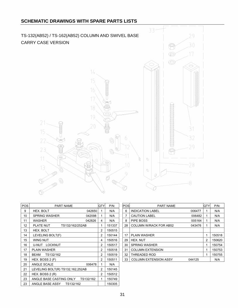
TS-132(AB52) / TS-162(AB52) COLUMN AND SWIVEL BASE CARRY CASE VERSION
POS PART NAME QTY P/N: POS PART NAME QTY P/N: 9 HEX. BOLT 042650 1 N/A 6 INDICATION LABEL 006477 1 N/A
10 SPRING WASHER 042098 1 N/A 7 CAUTION LABEL 006482 1 N/A 11 WASHER 042826 4 N/A 8 PIPE BOSS 005164 1 N/A 12 PLATE NUT TS132/162/252AB 1 151337 28 COLUMN W/RACK FOR AB52 043476 1 N/A 13 HEX. BOLT 2 150515 14 LEVELING BOLT(F) 2 150144 17 PLAIN WASHER 1 15051815 WING NUT 4 150516 29 HEX. NUT 2 15062016 U-NUT LOCKNUT 2 150517 30 SPRING WASHER 1 15075417 PLAIN WASHER 2 150518 31 COLUMN EXTENSION 1 15075318 BEAM TS132/162 2 150519 32 THREADED ROD 1 15075519 HEX. BOSS 2 (F) 2 150511 33 COLUMN EXTENSION ASSY 044125 N/A 20 ANGLE SCALE 006478 1 N/A 21 LEVELING BOLT(R) TS132,162,252AB 2 15014522 HEX. BOSS 2 (R) 2 15051223 ANGLE BASE CASTING ONLY TS132/162 1 15074923 ANGLE BASE ASSY TS132/162 150305