Embed Size (px)
Citation preview

TM 11-5820-453-10D E P A R T M E N T O F T H E A R M Y T E C H N I C A L M A N U A L
OPERATOR’S MANUAL
RADIO SETS AN/GRC-87 AND AN/VRC-34
H E A D Q U A R T E R S , D E P A R T M E N T O F T H E A R M Y10 MAY 1963

WARNING
HIGH VOLTAGEis used on this equipment
DEATH ON CONTACTmay result if safety precautions
are not observed.
DANGEROUS VOLTAGES ARE PRESENT AT THE FOLLOWING EQUIPMENT:Receiver-Transmitter RT-77 ( * ) /GRC-9 ................................................................. 425 to 580 volts dcDynamotor-Power Supply DY-88/GRC-9 ................................................................. 580 volts dcDynamotor-Power Supply DY-105 ( * ) /GRC-9X..................................................... 580 volts dc
Generator, Direct Current G-43/G 425 volts dc

Changes in force: C 1 and C 2TM 11-5820-453-10
C2
Change HEADQUARTERSDEPARTMENT OF THE ARMY
No. 2 Washington, D. C., 23 November 1978
Operator's ManualRADIO SETS AN/GRC-87 AND AN/VRC 34
TM 11-5820 453-10, 10 May 1963, is changed as follows:Page 3. Paragraph 2 is superseded as follows:
2. Indexes of Publications
a. DA Pam 310-4. Refer to the latest issue of DAPam 310-4 to determine whether there are neweditions, changes, or additional publicationspertaining to the equipment.
b. DA Pam 310-7. Refer to DA Pam 310-7 todetermine whether there are modification workorders (MWO's) pertaining to the equipment.
Paragraph 2.1 is superseded as follows:
2.1. Forms and Records
a. Reports of Maintenance and UnsatisfactoryEquipment. Maintenance forms, records, andreports which are to be used by maintenancepersonnel at all maintenance levels are listed in andprescribed by TM 38-750.
b Report of Packaging and HandingDeficiencies. Fill out and forward DD Form 6(Report of Packaging and Handling Deficiencies)
prescribed in AR 700-58 (Army) / NAVSUP PUB378 (Navy) / AFR 71-4 (Air Force) / and MCOP4030.29 (Marine Corps).
c. Discrepancy in Shipment Report (DISREP)(SF 361). Fill out and forward Discrepancy inShipment Report (DISREP) (SF 361) as prescribedin AR 55-38 (Army) / NAVSUP PUB 459 (Navy) /AFM 75-34 (Air Force) / and MCO P4610.19(Marine Corps).
Paragraph 2.2 is added after paragraph 2.1.
2.2. Reporting of Equipment PublicationImprovements
The reporting of errors, omissions, andrecommendations for improving this publication bythe individual user is encouraged. Reports should besubmitted on DA Form 2028, RecommendedChanges to Publications, and forwarded direct toCommander, US Army Electronics Command,ATTN: AMSEL-MA-C Fort Monmouth, NJ 07703.Page 9. Paragraph 5 is superseded as follows:
This publication has been printed by the UNITEDSTATES ARMY PUBLICATIONS DISTRIBU-TION CENTER, ST. LOUIS, MISSOURI, to meetyour needs on a timely basis.
1
}

5. Items Comprising Operable Radio Sets AN/GRC-87 (FSN 5820-543-1997)and AN/VRC-34 (FSN 5820-543-1996)
FSN Quantity Nomenclature, part No. and mfr code
AN/GRC-87 AN/VRC-34NOTE
The part number is followed by the applicable 5-digit Federal supply code formanufacturers (FSCM) identified in SB 708-42 and used to identifymanufacturer, distributor, or government agency, etc.
5820-243-0432 1 Antenna, AT-101/GRC-9: fixed type; 8 sect; 4.3 to 12 MHz freq. range; 107 ft 6 in. lgo/a (Stored on RL-29 when not in use)(Not installed)
5820-243-1413 1 Antenna AT-102/GRC-9: fixed type; 9 sect; 2 to 4.3 MHz 137 ft lg o/a w/provisions for shortingas required (Stored on RL-29 when not in use ) (Not installed) (Not mounted)
6135-669-6632 1 Battery, Dry BA-317/U: Stored in Bag CW-140/GRC-9 (Not installed)OR
6135-120-1007 1 Battery, Dry BA-48: Stored in Bag CW-140/GRC-9NOTE
Dry batteries shown are used with the equipment but are not considered part ofthe equipment. They will not be preshipped automatically but are to berequisitioned in quantities necessary for the particular organization inaccordance with SB 11-6
5995-196-9564 1 1 Cord Assembly CD-307-B: (65 in.) 22 awg; 5 ft 10-13/32 in. lg o/a MIL-C-3884; typene COS-2(22) MS-35760; 96906 (Stored in accessories bag) (Not installed)
5995-164-6457 2 1 Cord assembly, CD-1086 (7 ft): MIL-C-3432 SC-D-22829;80063 (Stored in accessories bag)(Not installed)
5995-162-6946 1 Cord Assembly, CD-119 (36 in): 18 awg; 3 ft 2 in. lg o/a; SC-C-26551; 80063 (Stored inaccessories bag) (Not installed) (Not mounted)
5820-237-7321 1 Counterpoise CP-12: radial type; SC-D-1038F; 80063 (Stored on RL-29 when not in use) (Notinstalled)
5820-224-4885 1 Counterpoise CP-13; radial type; SC-D-1038; 80063 (Stored on RL-29 when not in use) (Notinstalled)
6125-635-3770 1 1 Dynamotor, Power Supply DY-105/GRC-9X, DY-105A/GRC-9X, DY-105B/GRC-9X; for 24vDC input operation only; SC-DL-177015; 80063 (For 6v or 12v installation substituteDynamotor Power Supply DY-88/GRC-9 for Dynamotor Power Supply DY-105/GRC-9X,DY-105A/GRC-9X, DY-105B/GRC-9X) (Not mounted)
6125-321-5928 1 1 Dynamotor, Power Supply DY-88/GRC-9 for 6v, 12v or 24v, DC input operation (For 6v or 12vinstallation may be issued in lieu of DY-105/GRC-9X when DY-105A/GRC-9X is notavailable for issue) (Not installed) (Not mounted)
6115-501-0611 1 Generator, G-43/G: Hand gen; power output, 425v at 115 ma, 105v at 32 ma 6.3v at 2.5 amp,1.4v at 0.456 amp, HV-8% variance, LV 2% variance, 50-70 rpm: SM-D-202177; 80063(Stored in BAG CW-420/G when not in use) (Not installed)
5975-197-4252 1 Guy GY-12: ant. mast guy; 20 ft lg; SC-D-1072; 80063 (Stored in accessories bag) (Notinstalled)
5975-199-5072 1 Guy GY-42: used w/mast sect; 2 lgth 20 ft lg, SC-D-15884; 80063 (Stored in accessories bag)(Not installed)
5820-493-9361 1 Halyard, M-378: braided cotton; 9/16 in. dia, 80 ft lg: (Stored in accessories bag) (Notinstalled)
5820-408-3197 1 Halyard, M-379: in braided cotton, 9/64 in. dia 10 ft lg; SC-C-35483; 80063 (Stored inaccessories bag) (Not installed)
5965-162-7931 1 1 Headset, electrical H-16/U magnetic, 8000 ohm impedance, SC-D-14618; 80063 (Stored inaccessories bag) (Not installed)
5805-171-3370 1 1 Key J-45: 5½ in. lg x 4¼ in. wd x 6 in. h; SC-D-1059; 80063 (Stored in accessories bag) (Notinstalled)
5965-665-0590 1 1 Loudspeaker LS-203/U: LS-7A; blast proof type; PM field, 8 ohm voice coil, SC-DL-6420;80063 (Stored in accessories bag) (Not installed)
5820-503-2953 1 1 Mast Base MP-65-B: SC-D-2071; 80063 (Stored in accessories bag) (Not installed)5820-199-8131 3 3 Mast Section MS-116A: 39½ in lg x 0.393 in. dia; SC-DL-100588-MS1164; 80063 (Stored in
accessories bag CW-119/G) (Not installed)5820-199-8843 1 1 Mast Section MS-117A: 39½ in. lg x 0.373 in. dia; SC-D-12521; 80063 (Stored in accessories
bag CW-419/G) (Not installed)5820-199-8841 1 1 Mast Section MS-118A: 39½ in x 0.246 in. dia; SC-D-12521; 80063 (Stored in accessories
bag CW-419/G) (Not installed)
2

5. Items Comprising Operable Radio Sets AN/GRC-87(FSN 5820-543-1997) andAN/VRC-34 (FSN 58205431996)-Continued
FSN Quantity Nomenclature, part No. and mfr code
AN/GRC-87AN/VRC-86
6625-701-9103 1 1 Meter Field Strength ME-61/GRC: 6 in. lg x 5 in. w x 5 in h o/a (Stored in acces-sories bag) (Not installed)
5965-646-4678 1 1 Microphone, Carbon M-52/U: 40-1000 ohms at 1000 Hz; MlL-M-1119313; 81349;w/an end No. 4 (Stored in accessories bag) (Not installed)
5820-196-9041 1 1 Receiver-Transmitter RT-77/GRC-9, RT-77A/GRC-9: vehicular, transportable; xmtroutput 2S w cw, 8.5 phone; 2 to 12 MHz in 3 bands; 16 in lg x 12 in w x 8 in.h o/a; Sig Spec No. 271-3213; SC-DL-S7596; 80063 (Not installed)
8130-355-7616 1 Reel RL-28: for Guy-11 Guy 12; 6 , in Lg x 2 in w x 0.747 in. thk; SC-D-1064;80063 (Stored in accessories bag) (Not installed)
5820-030-2969 3 Reel RL-29: for sig counterpoise CP-12 and CP-13; 11 in lg x 5 in. w; SC-D-1040;80063 (Stored in accessories bag) (Not installed)
4020-240-2145 25 25 Rope RP-5: cotton core, 12 strands 3/16 in die 255 lbs min breaking strength(Stored in accessories bag) (Not installed)
4130-223-4612 4 Stake, Guy GP-27B: anchors guy; 7 9/16 in lg x 5/16 in dia No. SC-D-1063; 80063(Stored in accessories bag) (Not installed)
6145-160-S114 10 10 Wire W-128: Single No. 14 AWG cond, stranded, forty-one No. 30 AWG strands(Stored in accessories bag) (Not installed)
GROUP IDYNAMOTOR, POWER SUPPLY DY-88/GRC-9
5995-280-4264 1 1 Cable Assembly, Special Purpose, Electrical CX-2031A/U (8 ft) uses cord CO-212(Not installed)
6125-219-9988 1 1 Hardware Kit: for mtg DY-88/GRC-9 to vehicle (in cloth bag)GROUP III
DYNAMOTOR, POWER SUPPLYDY-l05/GRC-9X; DY-l05A/GRC-9X; DY-l05B/GRC-9X
6125-324-9039 1 1 Hardware Kit: f/mtg Dynamotor-Power Supply to vehicle; c/o lockwasher, nut, boltsin cloth bag; Amictool No. 25095 (in cloth bag)
5995-280-4264 1 1 Cable Assembly Special Purpose, Electrical: CX-2031A/U: (8 ft) uses cordage CO-212(Not installed)
GROUP IIIRECEIVER TRANSMITTER RT-77/GRC-9; RT-77A/GRC-9
5995-170-6877 1 1 Cable Assembly Special Purpose, Electrical: Interconnects Rec-xmtr; 23-1/8 in. Lgapprox SC-C-3SS01 (installed in equip)
6135-271-0407 1 1 Battery Dry, BA-1293/U: grid bias fv6 p/o rec (Not installed) (Not mounted)5820-537-3904 1 1 Receiver, Radio: part of RT-77/GRC-9; RT-77A/GRC-9; 10-1/2 in lg x 5-1/8 in.
h x 6-1/2 in. d o/a (Installed in case)5825-309-3200 1 1 Transmitter, Radio: part of RT-77/GRC-9; RT-77A/GRC-9; 10 5/8 in. Lg x 10 3/8
in. wd x 6 1/2 in. d o/a (installed in case)
Paragraph 5.1 is added after paragraph 5.
3

5.1. Running Spares
FSN Quantity Nomenclature, part No. and mfr codeRUNNINC SPARE ITEMS
5820-243-0432 1 Antenna, AT-101/GRC-9: Fixed type; 8 sect; 4 3 to 12 MHz freq range; 107 ft 6 in. lg o/a(Stored in bag CS419)
5820-199-8131 3 Mast Section MS-116A: 39 1/2 in. lg x 0.393 in. dia; SC-DL-100588; 80063 (Stored in bagCW 419/G)
5820-199-8843 1 Mast Section MS-117A: 39 1/2 in. lg x 0.373 in. dia; SC-D-12S21; 80063 (Stored in bagCW 419/G)
5820-199-8841 1 Mast Section MS-118A: 39 1/2 in. lg x 0.246 in. dia; SC-D-12S21; 80063 (Stored in bagCW 419/G)
RADIO SET AN/VRC-345820-199-8131 3 Mast Section MS-116A: 39 1/2 in. lg x 0.393 in. dia; SC-DL-100588; 80063 (Stored in
bag CW419/G)5820-199-8843 1 Mast Section MS-117A: 39 1/2 in lg x 0.373 in. dia; SC-D-12S21; 80063 (Stored in bag
CW419/G)5820-199-8841 1 Mast Section MS-118A: 39 1/2 in. lg x 0.246 in. dia; SC-D-12S21; 80063 (Stored in bag
CW4 19/G)DYNAMOTOR, POWER SUPPLY DY-88/GRC-9
5920-280-8604 5 Fuse, Cartridge: 2 amp MIL type FO8G2R00BOR
5920-280-3171 3 Fuse, Cartridge: 5 amp F08DS R00A.5920-280-3157 3 Fuse, Cartridge: 10 amp 32v; Buss type MDR-10-D-E5920-399-7760 3 Fuse, Cartridge: 20 amp 32v; Buss type MDR-20-D-E5920-280-3177 3 Fuse, Cartridge: 30 amp 32v; Buss type MDR-30-D-E
DYNAMOTOR, POWER SUPPLYDY-105/GRC-9X; DY-105A/GRC-9X; DY-105B/GRC-9X
5920-142-7346 4 Fuse, Cartridge: 3 amp Buss type AGU-35920-280-3157 4 Fuse, Cartridge: 10 amp MIL type F07A10R0B
RECEIVER, RADIO(FSN5820-S37-3904)
6240-155-8683 1 Lamp, Incandescent: 2v, 0.06 amp min bayonet base; GE No. S-49TRANSMITTER, RADIO(FSN 5825-309-3200)
6240-155-8683 1 Lamp, Incandescent: 2 v, 0.06 amp min bayonet base; GE S-496240-299-6970 1 Lamp, Glow: GE No. NE-47
4

Page 45. Appendix II is superseded as follows:
APPENDIX IIBASIC ISSUE ITEMS LIST
Section 1. INTRODUCTION
1. ScopeThis appendix lists basic issue items required by thecrew/operator for operation, and maintenance ofRadio Sets AN/GRC-87 and AN/VRC-34.
2. GeneralThis basic issue items list is a list, in alphabeticalsequence, of items which are furnished with, andwhich must be turned in with the end item.
3. Explanation of ColumnsThe following provides an explanation of columnsfound in the tabular listings:
a. Illustration. This column is dividedfollows:
(1) Figure number. Indicates the figure numberof the illustration in which the item is shown.
(2) Item number. Not applicable.b. Federal Stock Number. Indicates the
Federal stock number assigned to the item and willbe used for requisitioning purposes.
c. Part Number. Indicates the primary numberused by the manufacturer (individual, company,firm, corporation, or Government activity). whichcontrols the design and characteristics of the item bymeans of its engineering drawings, specificationsstandards, and inspection requirements, to identifyan item or range of items.
d. Federal SUPPY Code for Manufacturer(FSCM). The FSCM is a 5-digit numeric code usedto identify the manufacturer, distributor, orGovernment agency, etc., and is identified in SH 70842.
e. Description. Indicates the Federal item nameand a minimum description required to identify theitem.
f. Unit of Measure (U/M). Indicates the standardof basic quantity of the listed item as used inperforming the actual maintenance function. Thismeasure is expressed by a two-characteralphabetical abbreviation, (e.g., ea. in., pr, etc.).When the unit of measure differs from the unit ofissue, the lowest unit of issue that will satisfy therequired units of measure will be requisitioned.
g. Quantity Furnished with Equipment (BasicIssue Items Only). Indicates the quantity of thebasic issue item furnished with the equipment.
4. Special InformationUsable on codes are included in column 5. Uncodeditems are applicable to all models. Identification ofthe usable on codes are as follows:
Code Used on
1 ............................................AN/GRC-872 ............................................AN/VRC-34
5

Section II. BASIC ISSUE ITEMS LIST(1)
Illustration(2) (3) (4) (5) (6) (7)
(A)Fig.No.
(B)ItemNo.
Federalstock
number
Partnumber
FSC M Description
Usableon code
Unitof
meas.
Qtyfurnwithequip
1,2 5820-308-5817 BAG CW-140/GRC-9: for carryingReceiver and Transmitter RT-77/GR-9 wpcanvas; 14 in. lg x 14 in w x (Notinstalled) (Not mounted)
EA 1
1,2 5820-690-8541 SC-DL-31963 80063 BAG, COTTON DUCK, CW-419/GRC-9: 65-1/2 in. lg x 33 in. w w/approx. dimopened; 4 flap type and fixed type pockets(Replaces Roll BG-174 in AN/ GRC-9)(Not installed) (Not mounted)
EA 1
1 6115-709-0463 SC-DL-17336 80063 BAG,CW-420/G: for generator 1 15 1/2in. lg x 6 1/2 in. w x 11 3/4 in. h o/a olivedrab water repellent (Not mounted)
EA 1
1 5820-701-9097 SC-DL-74923 80063 BOX BX-53 D: (Stores in Bag CW-140/GRC-9 (Not installed)
EA 1
1 5820-129-9666 80063 BRACKET FT-515: used to mountInsulator IN-127: 6 1/2in.1g x l in. wd xl/8 in. thk (Stored in accessories bag)(Not installed)
EA 1
1 5965-243-0207 MIL-H-11190 81349 COVER, MICROPHONE CW-292-W:1.218 in. lg x 0.671 in. h x 0.605 in.dia; polyethylene (Stored in accessoriesbag)
EA 1
1 5970-227-8226 SC-DL-35528 80063 INSULATOR IN-127: cylindricalmolded phenolic; 12-21/ 32 in. lg,(Stored In accessories bag) (Notinstalled)
EA 1
1 5970-197-3576 SC-D-1134 80063 INSULATOR, STRAIN IN-86: Storedin accessories bag (Not installed)
EA 1
5820-128-2207 SC-C-20701 MOUNTING MT-350/GRC-9: 16-5/8in. lg x ll-9/16 in. w x 1-5/8 in. h (Notinstalled)
GROUP IIIRECEIVER TRANSMITTER
RT-77/GRC-9; RT-77A/GRC-9
EA 1
3 5820-545-8234 SC-D-35818 80063 CABINET: houses rec end xmtr; 15-1/2 in. lg x 10-1/2in.wd x 4 9/32 in. happrox o/a (Not installed)
EA 1
3 5820-691-2059 PANEL, COVER CW-109/GRC:water tight metal cover f/RT-77(*)/GRC-9; 11-1/2 in. lg x 16 1/2 in.wd w/3 in. fl (Mounted in equip)
RUNNING SPARE ITEMS RADIO SET AN/GRC-87 AND
AN/VRC-34
EA 1
5970-197-3576 SC-1134 INSULATOR, STRAIN IN-86:(Stored in Bag CW-419/G)
EA 2
6

By Order of the Secretary of the Army:CREIGHTON W. ABRAMSGeneral, United States ArmyChief of Staff
Official:VERNE L. BOWERSMajor General, United States ArmyThe Adjutant General
Distribution:To be distrib uted in accordance with DA Form 12-51 operator maintenance requirements for AN/GRC 87 and AH/VRC 34.
U.S. GOVERNMENT PRINTING OFFICE: 1973-7681 11/685

TM 11-5820-453-10
C 1
HEADQUARTERS
CHANGE DEPARTMENT OF THE ARMY
No. 1 Washington, D. C., 16 November 1967
OPERATOR'S MANUAL
RADIO SETS AN/GRC 87 and AN/VRC 34
TM 11-5820-453-10, 10 May 1963, is changed as follows:
Page 3. Make the following changes:
Delete paragraph 2 and substitute:
2. Index of PublicationsRefer to the latest issue of DA Pam 310-4 to de-
termine whether there are new editions, changes, oradditional publications pertaining to the equipment.
Add paragraph 2.1 after paragraph 2.
2.1 Forms and Recordsa. Reports of Maintenance and Unsatisfactory
Equipment. Use equipment forms and records inaccordance with instructions in TM 38-750.
b. Report of Packaging and HandlingDeficiencies. Fill out and forward DD Form 6(Report of Packaging and Handling Deficiencies) asprescribed in AR 700-58 (Army), NAVSUP
Publication 378 (Navy) AFR 71-4 (Air Force), andMCOP4610-5 (Marine Corps).
c. Discrepancy in Shipment Report (DISREP)(SF 361). Fill out and forward Discrepancy inShipment Report (DISREP) (SF 361) as prescribedin AR 55-38 (Army), NAVSUP Pub 459 (Navy),AFM 75-34 (Air Force), and MCO4610.19 (MarineCorps).
d. Reports of Equipment Manual Improvements.Reporting of errors, omissions, andrecommendations for improving this publication bythe individual user is encouraged. Reports should besubmitted on DA Form 2028 (RecommendedChanges to DA Publications) and forwarded directto Commanding General, U. S. Army ElectronicsCommand, ATTN: AMSEL. NMP-CR, FortMonmouth, N.J., 07703.
Page 44. Delete appendix I and substitute:
This publication has been printed by the UNITEDSTATES ARMY PUBLICATIONS CENTER,ST. LOUIS, MISSOURI, to meet your needs on atimely basis.
1
}

APPENDIX IREFERENCES
DA Pam 310-4 Index of Technical Manuals, Technical Bulletins, Supply Manuals (types 7,8 and 9), Supply Bulletins, and Lubrication Order
DA Pam Index of Modification Work OrdersTB SIG 109 Headset H-16/UTB SIG 330 Microphone M-52/U and M-52A/UTM 10-500-10 Airdrop of Supplies and Equipment: Rigging 1/4-ton Utility TrucksTM 11-5070 Power Supplies P-327/GRC-9Y, PP-327A/GRC-9Y, and PP-327B/GRC-
9YTM 11-5122 Direct Current Generator G-43/GTM 11-5820-479-12P Operator and Organizational Maintenance Repair Parts and Special Tools
List and Maintenance Allocation Chart: Mast Base MP-65, MP-65Aand MP-65B
TM 11-5965-212-15P Operator, Organizational, Field and Depot Maintenance Repair Parts andSpecial Tools List and Maintenance Allocation Chart: Microphone M-52/U and M-52A/U
TM 11-5965-213-l5P Maintenance Repair Parts and Special Tools List and MaintenanceAllocation Chart for Permanent Magnet Loudspeaker LS-203/U(including LS-7 and LS-7A)
TM 11-5965-267-15P Operator, Organizational, Field and Depot Maintenance Repair Parts andSpecial Tool List: Headset, Electrical H-16/U
TM 38-750 Army Equipment Record Procedures
Page 46, appendix II, section II. Add the followingitem in the columns indicated below:
FEDERAL STOCK NUMBER column:5820-701-9097DESIGNATION BY MODEL column, subcol-umn 1 and 2:
DESCRIPTION column: BOX BX-53-D: Sigdwg SC-DL-74923
Note: Stored in Bag CW-140/GRC-9(Not Installed)
QTY AUTH column: 1
By Order of the Secretary of the Army:HAROLD K. JOHNSONGeneral, United States Army
Official:_____________________________________________________ Chief of Staff
KENNETH G. WICKHAMMajor General, United States Army,The Adjutant General.
Distribution:To be distributed in accordance with DA Form 12-51 (Unclas) requirements for Organizational
maintenance, AN/GRC-87 and AN/VRC-34 Radio Sets.
2U.S. GOVERNMENT PRINTING OFFICE: 1967-302-011/857

*TM 11-5820-453-10TECHNICAL MANUAL HEADQUARTERS
DEPARTMENT OF THE ARMYNo. 11-5820-453-10 WASHINGTON 25, D.C., 10 May 1963
R A D I O S E T S A N / G R C - 8 7 A N D A N / V R C - 3 4
Paragraph PageCHAPTER 1. INTRODUCTION
Section I. GeneralScope ............................................................................................... 1 3Forms and records ............................................................................ 2 3
II. Description and data.........................................................................Purpose and use ............................................................................... 3 3Technical characteristics................................................................... 4 8Table of components ........................................................................ 5 9Description....................................................................................... 6 13Additional equipment required .......................................................... 7 14Differences in models ....................................................................... 8 17
CHAPTER 2. OPERATING INSTRUCTIONS
Section I. Operator's controls and indicatorsTransmitter subassembly of RT-77 (*)/GRC-9.................................. 9 18Receiver subassembly of RT-77 (*)/GRC-9 ...................................... 10 22Dynamotor-Power Supply DY-88/GRC-9......................................... 11 23Dynamotor-Power Supply DY-105 (*)/GRC-9X............................... 12 24Meter, Field Strength ME-61/GRC................................................... 13 25
II. Operation under usual conditionsTypes of operation............................................................................ 14 26Power supply preliminary starting procedure..................................... 15 26Receiver-transmitter starting procedure............................................. 16 27Receiver operation............................................................................ 17 27Transmitter dial setting procedure..................................................... 18 28Transmitter operation ....................................................................... 19 30Net operation.................................................................................... 20 33Antijamming .................................................................................... 21 33Stopping procedure........................................................................... 22 33
*This manual supersedes so much of TM 11-263, 20 June 1956' including Cl, 15 October 1957; C2, 29 April1960; C3, 15 November 1960; C4, 21 December 1961; C5, 23 November 1962, and C6, 17 April 1963, aspertain to the operation of subject equipment.
}

Paragraph Page
III. Operation under unusual conditionsGeneral ............................................................................................ 23 34Operation in arctic climates .............................................................. 24 34Operation in tropical climates ........................................................... 25 34Operation in desert climates.............................................................. 26 34
CHAPTER 3. MAINTENANCE INSTRUCTIONS
Scope of maintenance ....................................................................... 27 35Tools required for maintenance ......................................................... 28 35Preventive maintenance..................................................................... 29 35Maintenance service and inspection periods....................................... 30 35Daily maintenance service and inspection chart ................................. 31 36Cleaning........................................................................................... 32 41Removal and replacement procedures................................................ 33 42
CHAPTER 4. AUXILIARY EQUIPMENT
Purpose of auxiliary equipment......................................................... 34 43Power Unit PE-162-(*) ..................................................................... 35 43Power Supply PP-327(*)/GRC-9Y ................................................... 36 43
CHAPTER 5. DEMOLITION OF MATERIAL TO PREVENT ENEMY USE
Authority for demolition ................................................................... 37 43Methods of destruction ..................................................................... 38 43
APPENDIX I. REFERENCES................................................................................ 44
II. BASIC ISSUES ITEMS LIST ......................................................... 45

CHAPTER 1
INTRODUCTION
Section I. GENERAL1. Scope
a. This manual describes Radio Sets AN/GRC-87 and AN/VRC-34 (fig 1 and 2) and coversoperation and operator's maintenance. It includesoperation under usual and unusual conditions,cleaning and inspection of the equipment, andreplacement of parts available to first echelonmaintenance.
b. Official nomenclature followed by (*) isused to indicate all models of the equipment itemcovered in this manual. Thus, ReceiverTransmitterRT-77 (*)/GRC-9 represents Receiver-TransmittersRT-77/GRC-9 and RT77A/GRC-9; Dynamotor-Power Supply DY105 (*)/GRC-9X (power supplies)represents Dynamotor-Power Supplies DY-105/GRC-9X, DY-105A/GRC-9X, and DY-105B/GRC-9X; Power Units PE-162-(*) representsPE-162A, PE-162-B, and PE-162-C; Power SupplyPP-327 (*)/GRC-9Y represents Power Supplies PP-327/GRC-9Y, PP-327A/GRC-9Y, and PP-327B/GRC-9Y.
2. Forms and Records
a. Report of Maintenance and UnsatisfactoryEquipment. Use equipment forms and records in
accordance with instructions in TM 38-750.
b. Report of Damaged or Improper Shipment.Fill out and forward DD Form 6 (Report ofDamaged or Improper Shipment), as prescribed inAR 700-58 (Army), NAVSAN-DA Publication 378(Navy), and AFR 71-4 (Air Force).
c. Comments on Manual. Forward allcomments on this publication direct to: CommandingOfficer, U. S. Army Electronics Material SupportAgency, ATTN: SELMS-MP, Fort Monmouth, NewJersey, (DA Form 1598 (Record of Comments onPublications), DA Form 2496 (Disposition Form),or letter may be used. )
d. Index of Publications. Refer to the latestissue of DA PAM 310-4 to determine whether thereare new editions, changes, or additional publicationspertaining to your equipment. Department of theArmy Pamphlet No. 310-4 is a current index ofTechnical Manuals, Technical Bulletins, SupplyBulletins, Lubrication Orders, and ModificationWork Orders that are available through publicationssupply channels. The index lists the individual parts(-10, -20, -35P, etc.) and the latest changes to andrevisions of each equipment publication.
Section II. DESCRIPTION AND DATA
3. Purpose and Use
a. The radio sets covered in this manualprovide low-power, short-range (10- to 30-mile)communications capable of transmitting andreceiving radio signals in the frequency range of 2 to12 megacycles (mc). Each radio set can transmit andreceive (not simultaneously) continuous-wave (cw),modulated continuous-wave (mcw), and amplitude-
modulated (am.) radio signals.b. The AN/GRC-87 (fig. 1) may be used for
ground (man-transportable) or vehicularinstallations. The radio set may be operated as anisolated unit or in a net group.
c. The AN/VRC-34 (fig. 2) is installed andoperated in a vehicle and may be operated as anisolated unit or in a net group
3

Figure 1. Radio Set AN/GRC-87.4

1 Meter, Field Strength ME-61/GRC2 Generator, Direct Current G-43/G3 Dynamotor-Power Supply DY-105 (*) GRC-9X (or DY-88/GRC-9)4 Receiver-Transmitter RT-77 (*) /GRC-9 and Mounting MT-350/GRC-9 (hidden)5 Panel Cover CW-109/GRC-96 Bag CW-140/GRC-97 Tripod MT-1643/U (p/o G-43/G)8 Bag, Cotton Duck CW-420/G9 Crank, Hand GC-7 (p/o G-43/G)
10 Bag, Cotton Duck CW-419/GRC-911 Counterpoise CP-12 and CP-1312 Loudspeaker LS-203/U (or LS-7A)13 Guy GY-12 and GY-4214 Mast Sections MS-116A15 Mast Section ME-117A16 Mast Section MS-118A17 Cord CD-108618 Halyard M-378 and M-37919 Mast Base MP-65-B20 Insulator IN-12721 Bracket FT-51522 Battery, Dry BA-317/U23 Wire W-12824 Stake, Guy GP-27B25 Cable Assembly, Special Purpose, Electrical CX-2031A/U26 Antennas AT-101/GRC-9 and AT-102/GRC-927 Cord CD-111928 Key J-4529 Headset H-16/U30 Microphone, Carbon M-52/U31 Insulator, Strain IN-86
5

TM5820-453-10-15Figure 2. Radio Set AN/VRC-84.
6

1 Meter, Field Strength ME-61/GRC2 Dynamotor-Power Supply DY-105 (*) GRC-9X (or DY-88/GRC-9)3 Receiver-Transmitter RT-77 (*) /GRC-9 and Panel Cover CW-109/GRC and
Mounting MT-350/GRC-9 (hidden)4 Bag CW-140/GRC-95 Bag, Cotton Duck CW-419/GRC-96 Mast Base MP-65-B7 Wire W-1288 Microphone, Carbon M-52/U9 Key J-45
10 Loudspeaker LS-203/U (or LS-7A)11 Cord Assembly CD-108612 Mast Sections MS-116A13 Mast Section MS-117A14 Mast Section MS-118A15 Cable Assembly, Special Purpose, Electrical CX-2031A/U16 Headset H-16/U
7

4. Technical Characteristics
a. Receiver-Transmitter RT-77 (*) /GRC-9.Frequency range:
Band 1 .................................................................... 6.6 to 12mc.Band 2 .................................................................... 3.6 to 6 mc.Band 3 .................................................................... 2.0 to 3.6mc.
Transmitter:Type of modulation ...................................................... Amplitude .Type of transmission .................................................... Cw, mcw, and am. (voice).Type of control............................................................. Crystal or master-oscillator power amplifier.
Distance range:Cw signals:
Ground operation .................................................... 30 miles. 1
Vehicular operation ................................................ 15 miles. 1
Mcw signalsGround operation .................................................... 20 miles. 1
Vehicular operation ................................................ 10 miles. 1
Am. signal:Ground operation .................................................... 15 miles. 1
Vehicular operation ................................................ 10 miles. 1
Power output:Cw operation ............................................................... 15 watts, depending on frequency, antenna, and power
supply.Am. (voice) or mcw operation ...................................... 7 watts, depending on freque ncy, antenna and power
supplyAntennas:
Ground operation ......................................................... Whip or long wire.Vehicle operation ......................................................... Whip.
Number of tubes .............................................................. 5.Receiver:
Receiver type ............................................................... Am, superheterodyne.Types of signals received ............................................. Cw, mew, and am. (voice).Intermediate frequency ................................................. 456 kc.Method of calibration ................................................... Built-in crystal frequency calibrator.Calibration points ........................................................ Every 200 kc.Number of tubes........................................................... 7.Antenna ....................................................................... Same as transmitter.
Power supply:Vehicle installation (AN/GRC-87 and AN/VRC-34) .... Dynamotor-Power Supply DY-88/GRC-9 (used wi th a 6-, 12-, or
24-volt vehicle battery) or Dynamotor-Power Supply DY-105(*) /GRC-9X (used with a 24-volt vehicle battery).
Ground (man-transportable)installation (AN/GRC-87) ....................................... Generator, Direct Current G-43/G and Battery, Dry BA-317/U.
b. Dynamotor-Power Supply DY-88/GRC-9.Supply requirements:
Transmitter operation (high or low power):6-volt vehicle battery, high power ....................... 22.2 amperes;
low power ......................... 20 amperes.12-volt vehicle battery, high power ....................... 12.2 amperes;
low power ......................... 11.1 amperes.24-volt vehicle battery, high power ......................... 6.7 amperes;
low power ........................... 6.1 amperes.1 These values are approximations, since the range will vary considerably with terrain, frequency, and atmospheric conditions.
8

Receiver operation (standby):6-volt vehicle battery .................................................. 1.25 amperes.12-volt vehicle battery ................................................ 0.8 amperes.24-volt vehicle battery ................................................ 0.6 amperes.
Output power:Transmitter pa screen and plate power .............................580 volts dc at 0.1 ampere.Transmitter filaments .......................................................6.3 volts dc at 2 amperes.Receiver and low level tr ansmitter screen and
plate power ...................................................................105 volts dc at 0.045 ampere.Receiver filaments ............................................................1.4 volts dc at 0.5 ampere.Keying relay ....................................................................6.3 volts dc at 0.575 ampere.Standby receiver plates .....................................................105 volts dc at 0.017 ampere.
c. Dynamotor-Power Supply DY-105(*)/GRC-9X.
Supply requirements:Transmitter operation (high and low power),
24-volt vehicle battery, high power ..............................6.7 amperes;low power ...............................6.1 amperes.
Receiver operation (standby),24-volt vehicle battery ..................................................0.6 amperes.
Output power:Transmitter pa screen and power plate .............................580 volts dc at 0.1 ampere.Transmitter filaments .......................................................6.3 volts dc at 2 amperesReceiver and low level transmitter screen and
plate power ...................................................................105 volts dc at 0.045 ampere.Receiver filaments ............................................................1.4 volts dc at 0.5 ampere.Keying relay ....................................................................6.3 volts dc at 0.575 ampere.Standby receiver plates .....................................................105 volts dc at 0.017 ampere.
d. Generator, Direct Current G-43/G.
Supply requirements .............................................................Hand-operated.Full-load output:
Transmitter output:Plate power...................................................................425 volts at 0.115 ampere.Filament power.............................................................6.3 volts at 2.5 ampere.
Receiver output:Plate power...................................................................105 volts at 0.032 ampereFilament power .............................................................1.4 volts at 0.465 ampere.
Total power output ...................................................................85 watts (approximate).Cranking speed ........................................................................50 to 70 rpm
e. Meter, Field Strength ME-61/GRC.
Frequency range:Band 3 .............................................................................1.5 to 4 mc.Band 2 .............................................................................4 to 10 mc.Band 1 ................................................................... ........0 to 24 mc.
5. Table of Components
The components of the AN/GRC-87 and theAN/VRC-34 are listed in the basic issue items
list (appx II) and illustrated in figures 1 and 2
725-388-64-2 9

Figure 3. Receiver-Transmitter RT-77/GRC-9 and Panel Cover CW-l09/GRC
10

Figure 4. RT-77/GRC-9, receiver subassembly.
11

Figure 5. RT-77/GRC-9, transmitter subassembly.
12

6. Descriptiona. RT-77(*)/GRC-9. The RT-77(*)-GRC-9 (fig.
3) is common to both the AN/GRC-87 and theAN/VRC-34. It consists of a receiver (fig. 4) and atransmitter (fig. 5) subassembly mounted in a metalcase, which has a removable waterproof dust cover(CW-109/GRC-9). A metal grill protects thecontrols, binding posts, and connectors on the frontpanel of the subassemblies. The following items arelocated at the rear of the receiver-transmittersubassemblies.
(1) Interconnecting power cable and con-nectors.
(2) IMPEDANCE control on the receiversubassembly.
b. Power Supplies. The various power suppliesof the radio sets are described below:
(1) Dynamotor-Power Supplies DY-88/GRC-9 and DY-105(*)/GRC-9 (fig. 6and 7) are part of the AN/GRC-87 andthe AN/VRC-34. They are mounted inreinforced waterproof covers equippedwith shock-mounted fittings throughwhich bolts can be passed for vehicularmounting.
(2) Generator, Direct Current G-43/G(generator) consists of a generator unit,handcranks (GC-7), and a tripod (MT-1643/U). The generator u n i t i sh o u s e d a n d s h o c k - m o u n t e d
i n a waterproof aluminum case. Thetripod attaches to the -bottom of thealuminum case and has two tubular legsand one rectangular leg that has a seatattached to it. For further informationrefer to TM 11-5122.
c. Antennas. The antennas of the radio sets aredescribed below:
(1) The AT-101/GRC-9 (part of the long-wire antenna) (fig. 1) is part of theAN/GRC-87. It is made of strandedcopper wire, 107½ feet long, and issectionalized by eight ceramic insulatorsand eight sets of jumpers.
(2) The AT-102/GRC-9 (part of the long-wire antenna) (fig. 1) is part of theAN/GRC-87. It is made of strandedcopper wire, 137 feet long, and issectionalized by-eight ceramic insulatorsand eight sets of jumpers.
(3) Mast Sections MS-116A, MS-117A,and MS-118A are part of. the AN/GRC-87 and the AN/VRC-34. Thesemast sections are part of a whip antennaand are made of metal tubing withthreaded ends.
d. Field Strength Meter . Meter, Field StrengthME-61/GRC (fig. 8) is part of the AN/GRC-87 andAN/VRC-34. It is portable and is housed in a metalcase, which is waterproof when the cover is closed.
13

7. Additional Equipment Required
The following equipment is not supplied as partof, but is needled for use with, the radio sets:
a. Vehicular Storage Battery . A 6-, 12-, or 24-volt battery is required for use with Dynamotor-Power Supply DY-88/GRC-9 and a 24-volt batteryis required for use with Dynamotor-Power SupplyDY-105 (*) /GRC-9.
b. Frame FM-85. A frame mounting such as FM-85 is required for vertical mounting of the RT-
77(*)/GRC-9 in a vehicle.
c. Mast Bracket MP-50. The mast bracket isrequired when the radio set is mounted in a vehicleand Mast Base MP-65-B is to be used.
d. Oscillating Crystals. Crystal Unit CR-8/U,covering a frequency range from 1,000 kilocycles(kc) to 6,000 kc, is required when the transmitter ofthe RT-77 (*) /GRC-9 is crystal-controlled. (Stocknumbers of the available crystals are listed in SB 11-474.)
F i g u r e 6 . D y n a m o t o r - P o w e r S u p p l y D Y - 8 8 / G R C - 9
14
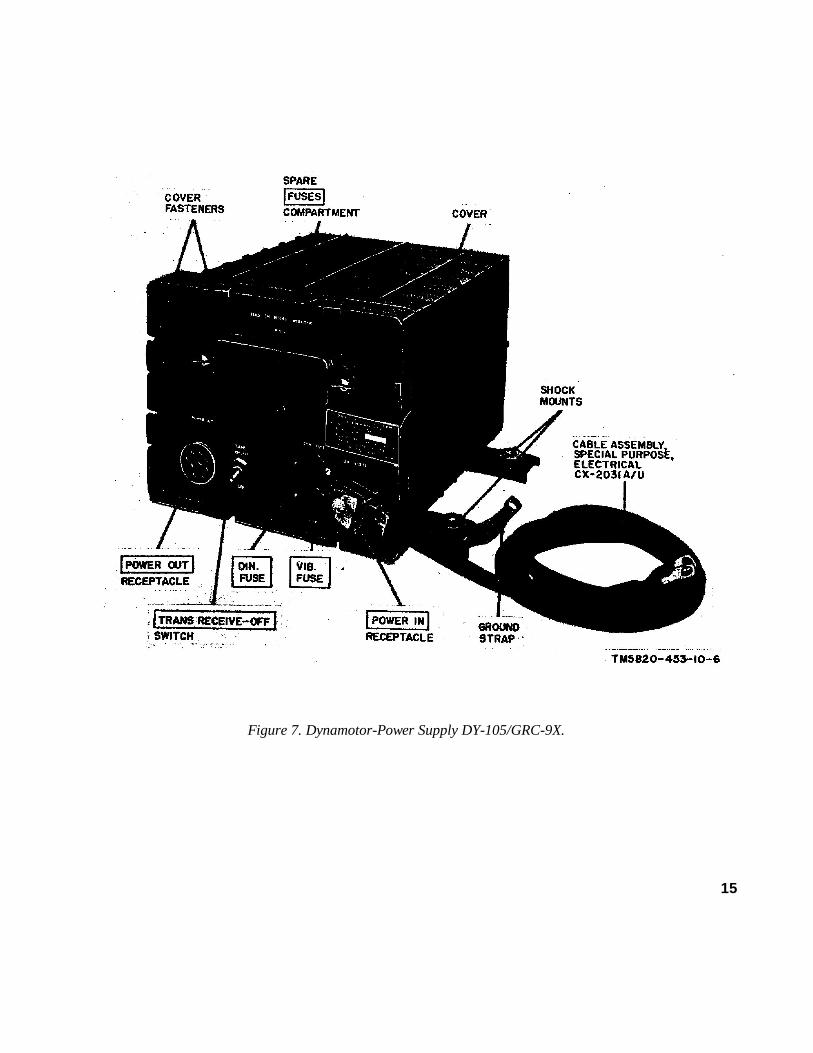
Figure 7. Dynamotor-Power Supply DY-105/GRC-9X.
15

F i g u r e 8 . M e t e r , F i e l d S t r e n g t h M E - 6 1 / G R C .
16

8. Differences in Models
a. Radio Set AN/GRC-87 is similar to Radio setAN/VRC-34 except for power supplies and antennasissued and certain modifications to improveoperational features. The differences are listedbelow:
b. Receiver-Transmitter RT-77 (*) /GRC-9. Themodels of the RT-77 (*) /GRC-9 (receiver-transmitter) are similar in appearance, purpose, andoperation, but differ as follows:
(1) The RT-77/GRC-9 has a wired-in type ofbias cell, and the RT-77A/ GRC-9 has a
new type of cell holder that permits the useof a plug-in bias cell battery (BA-1293/U).
(2) A lock is provided on some models toprevent control C (fig. 9), on the front panelof the transmitter subassembly, fromdetuning the radio set.
(3) The various models have some smallchanges in component values and circuitconfigurations
c. Dynamotor-Power Supply DY-105(*)/GRC-9.All models of the DY-105(*)/GRC-9X are similar inappearance, purpose, and operation; however, minorpart-value differences exist.
17

CHAPTER 2
OPERATING INSTRUCTIONS
Section I. OPERATOR'S CONTROLS AND INDICATORS
Note : This section covers only items used by the operator; items used by maintenancepersonnel are covered in instructions for the appropriate maintenance echelon .
9. Transmitter Subassembly of RT-77(*)/GRC-9(fig. 9)
Control or indicatorPanelletter Function
ANT.-DOUBLET binding posts ............................................................Provide connection points for the use of a whip, long-
wire or doublet antenna.
ANT. SELECTOR switch ..................................................................... (A) Eleven-position rotary switch.
INDICATOR neon lamp .......................................................................ANTENNA TUNING control ...............................................................Modulation-power switch ......................................................................
OFF-SEND-STANDBY switch ............................................................
(B)(C)(D)
(E)
Sw pos Antenna selected1 through 4 WHIP.5 through 8 REEL (long wire).9 through 11 DOUBLET.Transmitter tuning indicator.Tunes the transmitter to the antenna in useSix-position rotary switch.
Sw pos Type of operationPHONE
LO Voice transmission at low-poweroutput.
HI Voice transmission at high-poweroutput.
Sw pos Type of operationMCW:
LO Modulated mcw transmission atlow-power output.
HI Modulated mcw transmission athigh-power output.
CW:LO Cw transmission at low-power
outputHI Cw transmission at high-power
output.Three-position rotary switch.
Sw pos ActionOFF Radio set cannot transmit or re-
ceive.SEND Radio set can transmit or re-
ceive.STANDBY Permits reception only (except
when the input power sourceis the BA-317/U and G-43/G;then, transmission and recep-tion are possible).
18

Control or indicatorPanelletter Function
Oscillator-band switch ...........................................................................
SIDE TONE VOL. control ....................................................................
OSC. CAL CONTROL.........................................................................FREQ. CONTROL................................................................................
DIAL LIGHT SWITCH........................................................................KEY jack................................................................................................MIKE jack..............................................................................................
(F)
(G)
(H)(I)
(J)
Nine-position rotary switch.Sw pos Action
BAND 1(6.6 to 12 mc)
XTAL A Crystal A of BAND 1 controlsthe oscillator frequency.
XTAL B Crystal B of Band 1 controlsthe oscillator frequency.
MO Tuned circuit of BAND 1 con-trols the oscillator frequency.
BAND 2(3.6 to 6.6 mc)
XTAL A Crystal A of BAND 2 controlsthe oscillator frequency.
XTAL B Crystal B of BAND 2 controlsthe oscillator frequency.
MO Tuned circuit of BAND 2 con-trols the oscillator frequency
BAND 3(2 to 3.6mc)
XTAL A Crystal A of BAND 3 controlsthe oscillator frequency.
XTAL B Crystal B of BAND 3 controlsthe oscillator frequency.
MO Tuned circuit of BAND 3 con-trols the oscillator frequency.
Adjusts audio level sidetone heard at the headset orloudspeaker.
Calibration adjustment for transmitter tuning.Tunes transmitter to the desired operation frequency
(dial numbers ap pear in dial window and representcalibration chart settings for the desired frequency).
When depressed, illuminates dial window.Permits the use of a key for CW and MCW operation.Permits the use of a microphone to control modulation
during PHONE operation
19
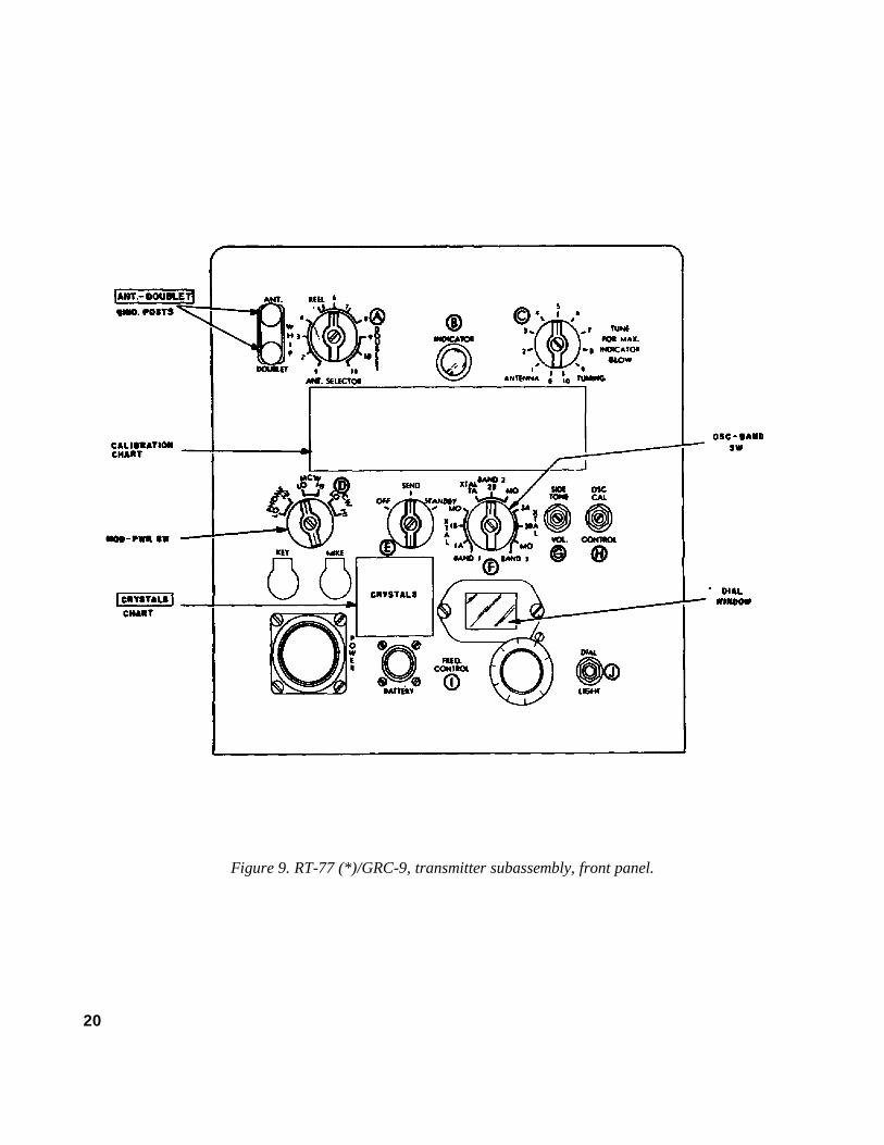
Figure 9. RT-77 (*)/GRC-9, transmitter subassembly, front panel.
20

TM5820-453-10-10
Figure 10. RT-77(*)/GRC-9, receiver subassembly, front panel.
21

10. Receiver Subassembly of RT-77 (*)/GRC-9 (fig. 10)
Control or indicatorPanelletter Function
DIAL LIGHT-PUSH switch ...........
Operation switch ..............................
Receiver band switch. ......................
Tuning control..................................A. F. GAIN control ..........................
R. F. GAIN control ..........................PHONES jacks.................................
IMPEDANCE switch (rear).............
(K)
(L)
(M)
(N)
(O)
(P)
When depressed, illuminates dial window.
Four-position switch.Sw pos Action
PHONE Allows voice and mcw reception.C. W. Allows cw reception by automatically turning on the bfo
stage.
NET Allows alignment of transmitter to the desired distant station.
CAL. Allows the receiver to be calibrated.
Three-position switchSw pos Action
BAND 1 6.6- to 12-mc frequency range (dial marks 60 kc apart).
BAND 2 3.6- to 6.6-mc frequency range (dial marks 20 kc apart).
BAND 3 2.0- to 3.6-mc frequency range
(dial marks 20 kc apart).Tunes the receiver and controls the operation of the
calibration dial. Dial numerals are in megacycles.Adjusts the audio signal level heard at the headset or
loudspeaker.Adjusts the receiver gain.Each jack serves the following purpose:
1. .A headset or loudspeaker connection to theaudio output.
2. Completes filament circuit when headset or loud-speaker is plugged into either jack.
Two-position switch that controls the audio outputimpedance.Sw pos Action
260 Permits a headset of 260 ohmsimpedance to be used for re-ception.
4000 Permits Loudspeaker LS-203/Uand Headset H-16/U to be used for reception.
.
22
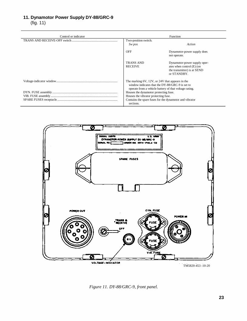
11. Dynamotor Power Supply DY-88/GRC-9(fig. 11)
Control or indicator FunctionTRANS AND RECEIVE-OFF switch ...........................................................
Voltage-indicator window...............................................................................
DYN. FUSE assembly ....................................................................................VIB. FUSE assembly ......................................................................................SPARE FUSES receptacle..............................................................................
Two-position switch.Sw pos Action
OFF Dynamotor-power supply doesnot operate.
TRANS AND Dynamotor-power supply oper-RECEIVE ates when control (E) (on
the transmitter) is at SENDor STANDBY.
The marking 6V, 12V, or 24V that appears in thewindow indicates that the DY-88/GRC-9 is set tooperate from a vehicle battery of that voltage rating.
Houses the dynamotor protecting fuse.Houses the vibrator protecting fuse.Contains the spare fuses for the dynamotor and vibrator
sections.
TM5820-453 -10-20
Figure 11. DY-88/GRC-9, front panel.
23

12. Dynamotor-Power Supply DY-105(*)/GR-9X(fig. 12)
Control or indicator FunctionTRANS AND RECEIVER-OFF switch ........................................................
Spare FUSES receptacle .................................................................................
DYN. FUSE assembly ....................................................................................VIB. FUSE assembly ......................................................................................
Two-position switch for controlling dynamotor operation.Sw pos Action
OFF Dynamotor does not operate.TRANS RECEIVE Dynamotor operates when con-
trol (E) (transmitter) is atSEND or STANDBY.
Contains spare fuses for the dynamotor and vibratorsections.
Houses the dynamotor protecting fuse (10 amperes).Houses the vibrator protecting fuse (3 amperes).
TM 5820-453-10-9
Figure 12. DY-105/GRC-9X, front panel
24

13. Meter, Field Strength ME -6 1/GRC(fig. 13)
Control or indicator FunctionBAND SWITCH................................ ................................ .........
TUNING control.............................................................................................
Meter ...............................................................................................................
Meter ...............................................................................................................
PHONES jack .................................................................................................
ANT ................................................................................................................
Three-position switch.Sw pos Action15-4 Frequency range of 1.5 to 4 mc
is selected.14-10 Frequency range of 4 to 10 mc
is selected.0-24 Frequency range of 10 to 24 mc
is selected.
Allows continuous tuning of field strength meter for the selected BAND SWITCH position.
Gives indication of radiation from transmitting an-tennas.
Adjusts the signal level indication of the panel meteron the field strength meter.
Permits a headset to be placed across the audio outputfor monitoring modulation.
Telescoping antenna for reception of transmitted fre-quencies.
TM5820-453-10-18
Figure 13. ME-61/GRC, front panel.
725-388 0-64-4
25

Section II. OPERATION UNDER USUAL CONDITIONS
14. Types of Operationa. Radio Sets AN-GRC/87 and AN/VRC- can
be voice, continuous-wave (cw), or modulatedcontinuous-wave ( mew ) operated. The AN/GRC-87 provides operation for ground and vehicularinstallations; the AN/ VRC-34 provides operationfor vehicular installations.
b. The operational procedure will vary with thetype of power supply used. To operate theequipment for the particular mode of operationrequired, perform the following procedures:
(1) Power supply preliminary startingprocedures (para 15).
(2) Receiver-transmitter starting procedure (para 16).
(3) Receiver operation (para 17).(4) Transmitter dial setting procedure (pare
18).(5) Transmitter operation (para 19).
15. Power Supply PreliminaryStarting Procedure
Choose the applicable power supply preliminaryprocedure listed below.
a. DY-88/GRC-9. Perform the preliminaryoperations listed below before starting the equipment(pare 16) .
(1) Turn the TRANS & RECEIVE-OFF switch to OFF.
(2) Check to see whether the voltage that appears in the voltage-indicator window agrees with the voltage of the vehicular battery. If it does not agree, request the unit repairman (or higher echelon) to correct the setting of the input voltage selector switch.
(3) Check the DYN. FUSE and the VIB. FUSE for the applicable fuse rating as indicated in the chart below:
Vehicular battery(volts)
DYN. FUSE(amperes)
VIB. FUSE(amperes)
61224
302010
52 (slo blo type)2 (slo blo type)
(4) Operate the TRANS & RECEIVEOFF switch to TRANS & RECEIVE.(3)
(5) Operate control (E) on the RT-77 (*)/GRC-9 to STANDBY and place onehand on the power supply case; vibrationswill be felt.
(6) Operate control (E) on the RT- (*) /GRC-9 to SEND; a steady hum from the power supply will be heard.
(7) Perform the procedure given in paragraph 16.b. DY-105(*)/GRC-9X. Perform the preliminary
operations listed below before starting the equipment(para 16).
(1) Operate the TRANS RECEIVE-OFF switch to OFF.
(2) Check the DYN. FUSE for a 10- rating, and the VIB. FUSE for a 3-ampere rating.
(3) Operate the TRANS RECEIVE-OFF switch to TRANS RECEIVE.
(4) Operate control (E) on the RT- ( * ) /GRC-9 to STANDBY and place one hand on the power supply case; vibrations will be felt.
(5) Operate control (E) on the RT- to SEND; a steady hum from the power supply will be heard.
(6) Perform the procedures given in paragraph 16.c. Generator, Direct Current G-43/G.
(1) Two operators are required when the G-43/G isused to operate the RT-77(*) /GRC-9 Oneoperator operates the receiver-transmitter. The other operator rotates the handcranks at approximately 1 revolution per second in the direction of the arrow stamped on the generatorhousing.
Caution: Do not turn the handcranks inthe opposite direction; this action will cause damage to the generator.
(2) The generator will supply power (when the generator handcranks are rotated) to the receiver and transmitter when control ( E ) on the RT- (*) /GRC-9 is set to SEND. If control (E) is set to STANDBY, then power will only be supplied to the receiver.
(3) If the BA-317/U (dry battery) and the G-43/Gare required to supply power to the RT-77(*)/GR~9, then set control (E) toSTANDBY. It will be necessary to rotate thegenerator handcranks during transmission butnot during reception. If control (E) is set toSEND, then power will be supplied to thetransmitter only.
26

(4) Follow the procedure given in paragraph 16.
16. Receiver-Transmitter StartingProcedure
Refer to paragraph 15 before starting theprocedures given below.
a. Operate control (E) to OFF.b. Check to see whether the headset or the
loudspeaker is plugged into the PHONES jack onthe receiver (the receiver filaments will not lightunless a headset or a loudspeaker is plugged into thePHONES jack.
c. Check to see whether the microphone or key isplugged into the MIKE and KEY jacks.
d. Check for the correct connections on thebinding posts for the antenna in use. Operate control(A) to the applicable position (refer tothe chart below).
Antennatype
Control (A)position
Binding post connections
Whip .................... ...
Long-Wire
Doublet............... ...
WHIP1, 2, 3 or 4........
REEL5, 6, 7, or 8.......
DOUBLET:9, 10, or 11 ......
ANT. and GND.
ANT. and GND.
ANT. and DOUBLET.
e. Adjust A.F. GAIN control (O) and R.F. GAINcontrol (P) maximum clockwise.
17. Receiver OperationRefer to paragraphs 15 and 16 before starting this
procedure; allow approximately 15minutes forequipment warmup.a. Calibrating.
(1) Operate control (L) to CAL. and control (E) to STANDBY.
(2) Operate control (D) to PHONE HI.(3) Operate control (M) to the band position
corresponding to the operating frequency.(4) Rotate control (N) to the 200-kc crystal
checkpoint nearest the operatingfrequency.
(5) Adjust control (O) to midposition and control (P) maximum clockwise.
(6) Adjust control (N) for a zero beat. The receiver is now calibrated to the crystal checkpoint.
b. Receiver Tuning. Refer to the chart below forthe applicable control position or adjustment of thedesired type of reception.
Control Control setting for type of reception
(E)(L)
(M)
(N)
(O)
(P)
Voice
STANDBYPHONE
Adjust to band position nearest op-erating frequency
Adjust to indicate the operatingfrequency.
Adjust for comfortable listeninglevel.
Adjust for maximum signal level..
Mew
STANDBYPHONE
Same as for Voice.
Same as for Voice.
Same as for Voice.
Same as for Voice.
Cw
STANDBY.C.W.
Same as for Voice.
Operate control slightly to the leftor right of operating frequencyto obtain audible tone.
Same as for Voice.
Same as for Voice.
27

18. Transmitter Dial SettingProcedure
a. General. Prior to operation, FREQ.CONTROL (I) on the transmitter subassembly ofthe RT-77(*)/GRC-9 (fig. 9) must be adjusted fortransmission on the assigned operating frequency.Adjustment of FREQ. CON- controls the dialsettings of two dials which are illustrated for typicalsettings in figure 15. The dial numbers do notrepresent numerical values of operating frequencies;they are used only to facilitate dial settingprocedures when the transmitter is being arrangedfor operation at a particular frequency. Dial settingnumbers are obtained from the dial calibration chartthat is located on the front panel of each transmitter.A typical chart is illustrated in figure 14. Threepossible procedures can be used to determine properdial settings for the assigned operating frequency:
(1) If the assigned operating frequency iswithin band 1, 2, or 3 (2 to 11.7 mc) andcan be evenly divided by 100, follow theprocedures in b below.
(2) If the assigned operating frequency iswithin band 2 (2 to 3.6 mc) or band 3 (3.6to 6.6 mc) and can be evenly divided by20, or if the assigned frequency is withinband 1 (6.6 to 11.95 mc) and can beevenly divided by 50, follow theprocedures in c below.
(3) If the assigned operating frequency doesnot meet the criteria specified in either (1)or (2) above, follow the procedures in dbelow.Note: Examples in the procedures of b, c, andd below reflect use of the typical dialcalibration chart illustrated in figure 14.However, data (dial-setting numbers) in thecalibration charts will differ for eachtransmitter. Therefore, when using theseprocedures to determine dial settings for aspecific transmitter, use the dial calibrationchart located on the front panel of thetransmitter.
b. Procedure 1.(1)Select, from the FREQ column of the chart,
the number that corresponds with theassigned operating frequency. For example,assume that the assigned operatingfrequency is 3,100 kc (BAND 1); thenselect 3100.
(2) Select, the number that is adjacent (on theright- hand side to the number selected in1) above. (This number is the requiredtransmitter dial setting for the assignedoperating frequency. For the given example,the dial setting number is 2310.
c. Procedure 2.(1) Select, from the FREQ column of the chart,
a number which is numerically closest tobut less than the assigned operatingfrequency. For example, assume that theassigned operating frequency is 5,540 kc(BAND 2); then, select 5500.
(2) Select, from the top row of one of the fivecolumns on the right-hand side of the FREQcolumn, a number that is equal to thedifference between the assigned operatingfrequency and the number selected in ( 1 )above. For the given example select 40.
(3) Select the number that appears at theintersection of the row for the numberselected in (1) above and the column for thenumber selected in (2) above. This numberis the required transmitter dial setting for theassigned operating frequency. For the givenexample, the dial setting number is 2284.
d. Procedure 3. When an assigned operatingfrequency requires the use of dial setting numbers(for adjustment of FREQ. CONTROL I) whichcannot be obtained directly from the dial calibrationchart (as in a or b above), required dial settings mustbe interpolated as described in (1) through (9)below.
Note: Terms such as Di, Fo, Fb, Db, Da, and Kcwill be designated to represent specific numbers thatwill be selected during the following procedures. Thenumbers selected will be used in the equation providedat the end of these procedures. Therefore, keep a recordof each number (and its designated term) obtained whileperforming the procedures.
(1) Designate the assigned operating frequencyas Fo. For example, assume that theassigned operating frequency is 9238.5 kc(BAND 1); then, Fo = 9238.5.
(2) Select, from the FREQ column of the chart,a number which is numerically closest tobut less than the assigned operatingfrequency. For the given example, select9000.
28

(3) Select, from the top row of one of the fivecolumns on the right-hand side of the FREQcolumn, a number which when added to thenumber selected in (2) above, will benumerically closest to but less than theassigned operating frequency. For the givenexample select 200, since 9000 + 200 =9200 and this number is numericallyclosest to, but less than, the assignedoperating frequency of 9,288.5.
(4) Designate the sum of the numbers selectedin (2) and (3) above as Fb. For the givenexample Fb = 9,200.
(5) Select the number that appears at theintersection of the row for the numberselected in (2) above and the column for thenumber selected in (3) above. Designatethis number as Db. For the given example,select 1911; then Db = 1911.
(6) Select, from the top row of one of the fivecolumns on the right-hand side of the FREQcolumn, a number which when added to thenumber selected in (2), above, will benumerically closest to but greater than theassigned operating frequency. For the givenexample select 250, since 9000 + 250 =9250 and this number is numericallyclosest to but greater than the assignedoperating frequency of 9,288.5.
(7) Select the number that appears at theintersection of the row for the numberselected in (2) above and the column for thenumber selected in (6) above. Designate thisnumber as Da. For the given example,select 1932; then Da = 1932.
(8) Use one of the following procedures toselect a number that will represent the termKc:
(a) If the assigned operating frequency iswithin band 2 (2 to 3.6 mc) or band 3 (3.6to 6.6 me), Kc = 20.
(b) If the assigned operating frequency iswithin band 1 (6.6 to 11.7 me), Kc = 50.Note: For the given example Kc = 60.
(9) Substitute, in the following equation, the numbers selected for Fo, Fb, Db, Da, and Kc and perform the required computation to find Di.Note: Di is the interpolated dial setting for the
transmitter.Fo is the assigned operating frequency in
kilocycles.Fb is a frequency that is listed in the dial
calibration chart and is numericallyclosest to but less than the assignedoperating frequency.
Db is a number in -the dial calibrationchart which represents a transmitterdial setting for a frequency listed inthe chart that numerically is closestto but less than the assignedoperating frequency.
Da is a number in the dial calibrationchart which represents a transmitterdial setting for a frequency listed inthe chart that is numerically closestto but more than the assignedoperating frequency.
Kc is the kilocycle separation betweenthe Kc columns on the dialcalibration chart.
Di = (Fo - Fb) X (Da - Db) + DbKc
= (9238.5 -9200) X (1932 - 1911) + 191150
= (38.5) X (21) + 191150
= 808.5 + 191150
= 16.17 + 1911= 1927.17
Note: Do not use numbers to the right of thedecimal; therefore, Di = 1927.
29

Figure 14. Typical transmitter dial calibration chart. TM5820-453-10-7
19. Transmitter OperationRefer to paragraphs 15 and 16 before starting this
procedure. Allow 15 minutes for equipmentwarmup.
a. Calibrating.(1) Calibrate the receiver (pare 17).(2) Set control (F) to MO for the band
associated with the operating frequency.(3) Set control (I) to indicate the proper dial
setting (pare 18) for the calibration checkfrequency (pare 17).
(4) Set control (L) to NET and control (D) toMC W or CW. (Calibration is notpossible in the PHONE position.)
(5) Set control (E) to SEND except when the power source is the G -43 /g and BA-317/U; then, set (E) to STANDBY.
(6) Set controls (O) and (P) to their midpositions.(7) Adjust the control (El) until zero beat is heard
from the headset or loudspeaker.(8) The transmitter is now calibrated on this band.
If other bands are to be used, repeat theprocedure given in (1) through (7) above foreach band.
b. Tuning. Refer to the following chart for theapplicable control setting for the type oftransmission required.
Control orindicator
Control setting for type of transmissionVoice Mew Cw
(E)
(F)
(D)
(I)
(J)
(A)
(B)
(L)
Set to SEND (set to STANDBY ifG 43/G and BA-317/U are thepower source).
Set to the required MO or XTAL.position for the applicable band ofoperation.
Set to PHONE-HI
Adjust to indicate dial setting for.the required frequency (pare 18).
Depress control if dial setting illum-ination is required (microphoneswitch must be depressed).
Set to highest numbered position fortype of antenna used (pare 16).
Align red dots
Set to PHONE.
Same as for Voice.
Same as for Voice
Set to MCW HI.
Same as for Voice.
Depress control if dialsetting illumination isrequired
Same as for Voice.
Same as for Voice.
Same as for Voice.
Same as for Voice
Same as for Voice.
Set to C.W. HI
Same as for Voice
Same as for Mcw..
Same as for Voice.
Same as for Voice.
Set to CW HI.
30

Control orindicator
Control setting for type of transmissionVoice Mew Cw
Microphone(M-52/U ) orkey (J-45)
Meter, FieldStrengthME-61/GRC.
Depress the microphone switch andperform the following:
(1) Adjust control (C) untilINDICATOR (B) glows atmaximum. If INDICATOR(B) does not glow, set con-trol (A) to the next lower number until maximum glow is indicated.
(2) Depress microphone button;wait 2 seconds, and speakinto microphone. Establishcommunication.
The ME-61/GRC is used whena more accurate tuning indicationthan INDICATOR (B) is required.Follow procedures indicated belowafter the above tuning steps have been completed:
(1) Extend ME-61/GRC tele-scoping antenna (fig. 8).
(2) Set ME-61/GRC B A N DSWITCH (fig. 13) to rangeof required frequency.
(3) Depress microphone switchand place ME-61/GRC justclose enough to the radiat-ing (rf field) antenna tocause an indication on theME-61/GRC.
Warning: Do not touchtransmitting antenna withME 61/GRC telescoping an-tenna; serious rf burns andequipment damage may oc-cur.
(4) Adjust t h e ME-61/GRCTUNING control (fig. 13)for maximum indication (ifnecessary, reduce the meterindication by adjusting theME-61/GRC METER SEN-SITIVITY control (fig. 13)
(5) Adjust transmitter control(C) for maximum indicationon ME-61/GRC.
(6) Plug headset into PHONESjack of ME-61/GRC to mon-itor the modulated signal.
(7) Release microphone switch.(8) Establish communications
Close key and performthe following:
(1) Same as forVoice.
(2) Key transmitterand establishcommunication
Same as for Voice..
Close key and performthe following:
(1) Same as forVoice.
(2) Same as forMcw.
Same as for Voice.
31

TM5820-453-10-12- 12
Figure 15 Typical transmitter dial settings32

20. Net OperationIn net operation, all transmitters and receivers are
tuned to the same frequency as determined by thenet-control station. All operators in the net will tunetheir radio sets as directed below.
a. The net-control station operator will performthe procedures outlined in paragraphs 16 through 19and transmit a continuous signal at the net operatingfrequency.
b. Each station operator will conduct thefollowing tuning procedure:
(1) Set control (E) to SEND except when thepower supply consists of the G-43/G andthe BA-317/U; then, set it to STANDBY.
(2) Set control (L) to C.W.(3) Adjust control (N) to obtain a zero beat
with the net-control station signal.(4) Set control (L) to NET.(5) Set control (D) to CW LO.(6) Set control (I) to indicate the dial setting
for the net-control station frequency (pare18).
(7) Adjust control (H) to obtain a zero beat.(8) Adjust control (C) (only a slight
adjustment is necessary ) for a maximumglow on INDICATOR (B) or for amaximum indication on the ME-61/ GRC.
(9) Adjust controls (D) and (I) as required(pare 17, 18, and 19).
21. AntijammingWhen it is known, under real or simulated tactical
conditions, that the receiver is being jammed, the
operator will promptly notify the immediate superiorofficer and continue to operate the equipment. Toprovide maximum intelligibility of jammed signals,follow the procedure given below:
a Rotate control ( N ) several degrees on eitherside of the desired signal; this action may causesome separation of the desired signal and thejamming signal.
b. Vary R.F. GAIN control (P); this action mayreduce the jamming signal enough to permit thedesired signal to be heard.
c. Vary A.F. GAIN control (O); this action mayraise the level of the desired signal enough to beheard.
d. If the procedures given above do not provideenough signal separation for operation, change to theauthorized alternate frequency and alternate the callsign.
22. Stopping Procedurea. Turn control (E) to OFF.b. Turn off the applicable power supply as
follows:(1) Dynamotor-Power Supply DY-88/ GRC-9.
Operate the TRANS & RECEIVE-OFFswitch to OFF.
(2) Dynamotor-Power Supply DY105(*)/GRC-9X. Operate the TRANS RECEIVE-OFF switch to OFF.
(3) Generator, Direct Current G-43/G. Stopturning the handcranks.
33

Section III. OPERATION UNDER UNUSUAL CONDITIONS
23. GeneralThe radio equipment may have to be operated in
regions where extreme cold, heat, humidity or othermoisture, or sand conditions prevail. Althoughevery precaution is taken in the design of theequipment to maintain its technical characteristicsover a wide temperature and humidity range, adverseconditions may cause poor transmission andreception unless additional precautions are taken.Paragraphs 24, 25, and 26 provide procedures thatminimize the effects of these unusual climaticconditions.
24. Operation in Arctic ClimatesSubzero temperature and climatic conditions
associated with cold weather affect the efficientoperation of the system. Observe the followinginstructions and precautions when operating undersuch unusual conditions:
a. Keep the equipment warm and dry.b. Avoid the excessive use of lubricants.c. When the equipment that has been exposed to
the cold is brought into a warm room, moisture willform and remain on the equipment until it reachesroom temperature. This may cause a change in theoperating characteristics. When the equipmentreaches room temperature, dry it thoroughly.
25. Operation in Tropical ClimatesWhen operating in tropical climates, the equipmentmay be installed in tents, huts, or, when necessary,in underground dugouts. If the equipment is installedin dugouts or in swampy areas, moisture conditionsare more acute than normal. The high relativehumidity causes condensation to form on theequipment. To minimize this condition, provide thebest possible ventilation and dry the equipmentthoroughly. Place lighted electric light bulbs near theequipment to aid in preventing condensation fromforming.
26. Operation in Desert Climatesa. The main problem that arises with equipment
operation in desert areas is the large amount of sand,dust, or dirt that enters the moving parts.
b. Be careful to keep the equipment as free fromdirt as possible. Make frequent maintenance checks.
c. Never tie power cords or other wiringconnections to the inside or the outside of tents.Desert areas are subject to sudden wind squallswhich may jerk connections loose or break the lines.
d. A drop in temperature during the night oftencauses condensation on the equipment the followingday; dry the equipment thoroughly.
34

CHAPTER 3MAINTENANCE INSTRUCTIONS
27. Scope of MaintenanceThe maintenance duties assigned to the operator of
Radio Sets AN/GRC-87 and AN/VRC- are listedbelow, together with a reference to the paragraphcovering the specific maintenance function.
a. Daily maintenance service and inspection (para31).
b. Cleaning (para 32).c. Repairs.
(1) Replacement of receiver dial lamp(para 33a).
(2) Replacement of transmitter dial lamp (para 33b).
(3) Replacement of INDICATOR (B) lamp (para 33c).
(4) Replacement of panel fuses (para 33d ).
28. Tools Required For MaintenanceThe duties assigned do not require tools or test
equipment other than those issued with the radio set.
29. Preventive MaintenancePreventive maintenance is the systematic care,servicing, and inspection of equipment to prevent theoccurrence of trouble, to reduce downtime, and toassure that the equipment is serviceable.
a. Systematic Care. The procedures given inparagraphs 30, 31, and 32 cover systematic careessential to proper upkeep and operation of theequipment. The cleaning operations (pare 32)should be performed once a day. If the equipment isnot used daily, however, the cleaning operationsmust be performed before operation, or once a weekwhile the equipment is kept in standby condition.The other items must be checked before theequipment is placed in operation after any extendedshutdown, during operation, or after it is turned off,as specified in the applicable paragraph.
b. Maintenance Service and Inspection. Themaintenance service and inspection chart (para 31)
outlines inspections to be made at specific intervals.These inspections are made to maintain combatserviceability; that is, to make sure that theequipment is in good general (physical) condition, ingood operating condition, and likely to remaincombat serviceable. To assist operators inmaintaining combat serviceability, the chartindicates what to inspect, how to inspect, and whatthe normal conditions are; the References columnlists the paragraph that contains additionalinformation. If the defect cannot be remedied by theoperator, higher echelon maintenance or repair isrequired. Records and reports of these inspectionsmust be made in accordance with TM 38-750.
30. Maintenance Service andInspection Periods
a. Maintenance service and inspections of theAN/GRC-87 and AN/VRC-34 are required on adaily basis.
b. Paragraph 31 specifies services and inspectionsthat must be made daily and under the specialconditions listed below.
(1) In vehicular installations.(a) Before the vehicle starts on a mission.(b) When the equipment is initially installed.(c) When the equipment is reinstalled after
removal for any reason.(d) At least once each week if the equipment
is maintained in standby condition.(2) In transportable and mobile installations.(a) When the equipment is initially installed.(b) When the equipment is reinstalled after
removal for any reason.(c) At least once each week if the equipment
is maintained in standby condition.
35

31. Daily Maintenance Service and Inspection Chart
ItemNo.
ProcedureItem Normal Condition or result References
1 SET: Inspect the equipment for:a. Completeness.
b. Cleanliness (service).
c. Waterproofing.
a. Equipment must be complete andinstalled for operation.
b. Units must be clean and dry, freeof grease, dirt, rust, corrosion, and fungus.
c. Waterproof gaskets (exterior)are in good condition.
a. Appx II.
b. Pars 32.
c. None.
2 PUBLICATIONS: check to see thatthe pertinent publication is avail-able.
Operator's manual is complete andin usable condition.
Appx I.
4 LUBRICATION: Check lubricationon the equipment
Mechanisms should not show signsof overlubrication or underlubri-cation
Para 29b.
5 CONNECTIONS: Inspect the fol-lowing:
a. Cords, connections, cables, andwires.
b. Telegraph key, headset, loud-speaker, and microphone.
a. Cords, cables, and wires are freefrom cuts, breaks, fraying, de-terioration, kinks, and strain.
b. Plugs and sockets are clean, in-tact, and not loose-fitting. Micro-phone and telegraph key are con-nected to the proper jacks on thetransmitter. Headset and loud-speaker are connected to theproper jack on the receiver.
a. None.
b. Para 32.
6 MOUNTING: Inspect seating andstability of mountings. Check forloose or missing hardware.
Mounting shows no evidence ofweakness or deformity. All bolts,nuts, and washers are presentand properly tightened.
None.
8 FUSES: Cheek for proper fuses.
a. Dynamotor-Power Supply Dy-88/GRC-9
b. Dynamotor-Power Supply DY-105 (*)/GRC-9X.
The fuses in use, and the spares,are of the values indicated inchart below:a. DY-88/GRC-9 front panel:
DYN. FUSEa VIB. FUSEa
( amperes ) (amperes)
30 (6-volt 5battery)20 (12-volt 2 (slo blo type)battery)10 (24-volt 2 (slo blo type)battery)
a 1 each spare is located in the spareFUSES compartment.b DY-105(*)/GRC-9X front panel:
1 ea 10-amp fuse (DYN. FUSE)and 1 ea 3-amp fuse (VIB.FUSE )in use. 1 ea 10-amp and1 ea 3-amp fuse in spare FUSEScompartment.
Para 33d.
36

ItemNo.
ProcedureItem Normal Condition or result References
10 KNOBS, DIALS, and SWITCHES:Check for proper mechanical ac-tion by setting each control toeach of its positions
Action is positive without backlash,or scraping.
Note: Knobs that require frequenttightening should have setscrews replaced.
None.
11 ANTENNA: Inspect the installedantenna (whip or long-wire)
Antenna is complete, guy wires (ifrequired) are correctly installed,and insulators are free fromcracks, dirt, and fungus.
None.
12 OPERATIONAL PRESET; POWERSUPPLY: Set the controls of theapplicable power supply.a. DY-88/GRC-9 TRANS & RE
CEIVE-OFF: OFF'.b. DY-105(*)/GRC-9X TRANS.
RECEIVE-OFF: OFF.c G-43/G: Do not turn hand-
cranks.
a. All controls must be set properly.
b. All controls must be set properly
c. All controls must be set properly.
a. None.
b. None.
c. None.
13 OPERATIONAL PRESET; RECEIVER-TRANSMITTER: Setthe controls of the receiver-transmitter:(E) OFF(A): WHIP, REEL (long-wire )
or DOUBLET (set toindicate the antenna inuse) .
(O): Maximum clockwise.(P): Maximum clockwise.
All controls must be set properly. None.
14 START; POWER SUPPLY: Set the.controls of the applicable powersupply.a. DY-88/GRC-9: Set power
switch to TRANS & RECEIVE.b DY-105 ( * ) /GRC-9X: Set power
switch to TRANS RECEIVE.c. G-43/G: Do not turn hand-cranks.
All controls are set properly
a. None.
b. None.
c. None.
15START; RECEIVER-TRANSMIT-
TER: Set the controls of the re-ceiver-transmitter:
(E): STANDBY(D): PHONE HI(F): Set to desired band
(BAND 1, 2, or 3) andoscillator operation(XTAL or MO).
(I): Set to indicate requiredfrequency
(M): Set to indicate requiredband
(K): Depress the control andthen release it.
If the DY-88/GRC-9 or the DY-105(*)/GRC-9X is used (as apower supply); vibrations shouldbe felt on power supply case. Thereceiver dial light will be lightedwhen control (K) is depressed,and noise output is heard fromthe headset and speaker. If theG-43/G is used (as the powersupply), turn the handcranks;the receiver dial light will lightwhen control (K) is depressedNoise output is heard from theheadset or loudspeaker.headset or loudspeaker.Note: If BA-317/U is used with the G-
43/G, turn the handcranks only when trans-mitting (control (E) at STANDBY).
Para 18 and 33a
37

ItemNo.
ProcedureItem Normal Condition or result References
16 CALIBRATE THE RECEIVER:a. Set control ( L ) to CAL.b. Set control (L) to the 200-kc
checkpoint nearest the required frequency.
c. Adjust control (N) to zero beat.
a. Control ( L) is set properly.b. A tone is heard from the headset
and loudspeaker
c. Control (N) is adjusted for zerobeat.
a None.b. None.
c. None.
17 CALIBRATE THE TRANSMITTER:The receiver must be calibratedbefore performing the proceduresgiven below.a. Set control (F) to MO for the
required band of operation.b. Determine the dial setting from
the calibration chart, using thereceiver checkpoint frequency,and set control (I) to indicatethat dial setting.
c. Set control (L) to NET.d. Set control ( D ) to CW or MCW.e. Set control (E) to SEND ex-
when the power supply isthe G-43/G combined with theBA-317/U; then, set it toSTANDBY.
f . Adjust control (H) to zero beat.
a. Control (F) is set to MO on therequired band of operation.
b. Control (I) is set properly.
c. Sidetone is silenced.d. Control ( D ) is set properly.e. Control (E) is set properly.
f. Control (H) is adjusted for zerobeat.
a. None.
b. Para 18.
c. None.d. None.e. None.
f. None.
18 VOICE OPERATION:a. Set control (D) to PHONE HI.b. Set control (L) to PHONE.
a. Control ( D ) is set properly.b. Noise or voice signals are heard
in the headset or loudspeaker.
a. None.b. None.
W A R N I N G : T H E F O L L O W I N G P R O C E D U R E S R E Q U I R E T H E B R E A K I N G O F R A D I O S I L E N C E . T H I SM A N U A L D O E S N O T A U T H O R I Z E T H E B R E A K I N G O F R A D I O S I L E N C E I M P O S E D B Y A N Y C O M M A N D .U N A U T H O R I Z E D V I O L A T I O N O F R A D I O S I L E N C E C O U L D R E S U L T I N C O U R T S M A R T I A L O R P O S S I B L YDEATH FROM A HOSTILE FORCE .
c. Set control (1) to indicate thedial setting for the authorizedtesting or operating frequency.
d. Set control (N) to indicate au-thorized testing or operating frequency
e . Set control (E) as follows:(1) Set to SEND for operation
with DY-88/GRC-9 DY-105 (*) /GRC-9X, or G-43/G(turn handeranks).
(2) Set to STANDBY for op-eration with G-43/G andBA-317/U. Turn hand-cranks only when transmit-ting
f. Depress microphone switch andadjust control (C) for maxi-mum indication on INDICA-TOR (B) or ME-61/GRC.
c. Control (I) is set to indicate
d. Control (N) is set to indicateoperating frequency.
e. Control (E) is set properly.
f. INDICATOR (B) or ME-61/GRCindicates maximum.
c. Para 18.
d. None.
e. Para 33c
f. None.
38

ItemNo.
ProcedureItem Normal Condition or result References
g. Speak into microphone (microphone switch is depressed), establish communications, and vary control (G) through its entire range.Note Wait 2 seconds after microphone button is
depressed before starting to speakh. Depress microphone button and control (J ) . Release microphone button and control (J).
i. Depress and release control (K).
j. During reception, vary controlthrough its entire range.
k. During reception, vary controlthrough its entire range
g. Communication is establishedand sidetone level changes from zero to maximum as control (G ) is varied.
h. Transmitter dial light will light when control (J) is depressed and will extinguish when the microphone button or control (J) is released.
i. Receiver dial light will lightwhen control (K) is depressed and extinguish when it is released.
j. Audio level changes from zero to maximum as control (O) is varied.
k. Signal level changes from zero to maximum as control (P) is varied.
g. None.
h. Para 33b.
i. Para 33a.
j. None.
k None.
19 CW OPERATION:a. Set control (D) to CW HI.b. Set control (L) to C.W.
c. Set control (I) to indicate dialsetting for authorized testingor operating frequency.
d. Set control (N) to indicate au-thorized testing or operating
frequency.e. Set control (E) as follows:
(1) Set to SEND for operationwith DY-88/GRC-9, DY-(*) /GRC-9X, or G-43/G (turn handcranks).(2) Set to STANDBY for
operation with G-43/G andBA-317/U. Turn handcranks only when transmitting.
f. Close key (J-45) and adjustcontrol (C) for maximum indi-cation on INDICATOR (B) orME-61/GRC. Release key.
g. Key transmitter and establishcommunication with authorized
distant station.h. During transmission, vary con-
trol (G) through its entirerange.
i. During reception. vary control(O) through its entire range.
j. During reception, vary control(P) through its entire range.
a. Control (D) is set properly.b. Control (L) is set properly
and noise or cw signals are heard in headset or loudspeaker.
c. Control ( I ) is set to indicateproper dial setting.
d. Control ((N)) is set to indicate the proper frequency.
e. Control (E) is set properly.
f. INDICATOR (B) or ME-61/GRC indicates maximum.
g. Communication is established
.h.. Sidetone level varies from
zero to maximum.
i. Audio level changes from zero to maximum.
j Signal level varies fromzero to maximum.
a. None.b. None.
c. Para 18.
d. None.
e. None.
f. Para 33c
.g. None
.h. None.
i. None
.j. None.
_
39

ItemNo.
ProcedureItem Normal Condition or result References
20MCW OPERATION:
a. Set control (D) to MCW HIb. Set control (L) to PHONE
c. Set control (I) to indicate dialsetting for the authorized test-ing or operating frequency(par 18).
d. Set control (N) to indicate theauthorized testing or operatingfrequency.
e. Set control (E) as follows:.(1) Set to SEND OR opera
ion with DY-105 ( * ) /GRC-9X, or G-
43/G (turn handcranks).(2) Set to STANDBY for op-
eration with G-43/G andBA-317/U. Turn hand-cranks only when transmitting.
f. Close key (J -45 and adjust control (C) for maximum indication on INDICATOR B or ME-61/GRC. Release key.
g. Key transmitter and establish.communication with authorized distant station
h. During signal transmission,vary control (G) through its
entire range.i. During reception, vary control
(O) through its entire range.j. During reception, vary control
(P) through its entire rangek. Depress and release controls.
(J) and (K).
a. Control (D) is set properlyb. Noise or mew signals are
heard in headset or loudspeaker.
c. Control (I) is set properly.
d. Control (N) is set properly.
e. Control (E) is set properly
f. INDICATOR (B) or ME-61/GRC
g. Communication is established
h Sidetone level varies from zero to maximum.
i. Audio level varies from zero to maximum
j. Signal level varies from zero to maximum.
k. Dial lamps light end extinguish
a. None.b. None.
c. Para 18.
d. None.
e. None
.f. Para 33c.
g. None.
h. None
.i. None.
j. None.
k Para 33a and b
,.
.
40.

32. CleaningInspect the exteriors of the receiver-transmitter
and the power supply in use. The exterior surfacesshould be free of dust, grease, and fungus.
a. Remove dust and loose dirt with a clean softcloth.Warning: Cleaning compound is flammable andits fumes are toxic. Provide adequate ventilation.Do not use near a flame.
b. Remove grease, fungus, ground-in dirt from thecases; use a cloth dampened (not wet) with CleaningCompound (Federal stock No. 7930-395-9542).
c. Remove dust or dirt from plugs and jacks witha brush.
d. Clean the front panels and control knobs; use asoft clean cloth. If difficulty in removing dirt occurs,dampen the cloth with water; mild soap may be usedto make the cleaning more effective.
Figure 16. Receiver dial lamp removal
41
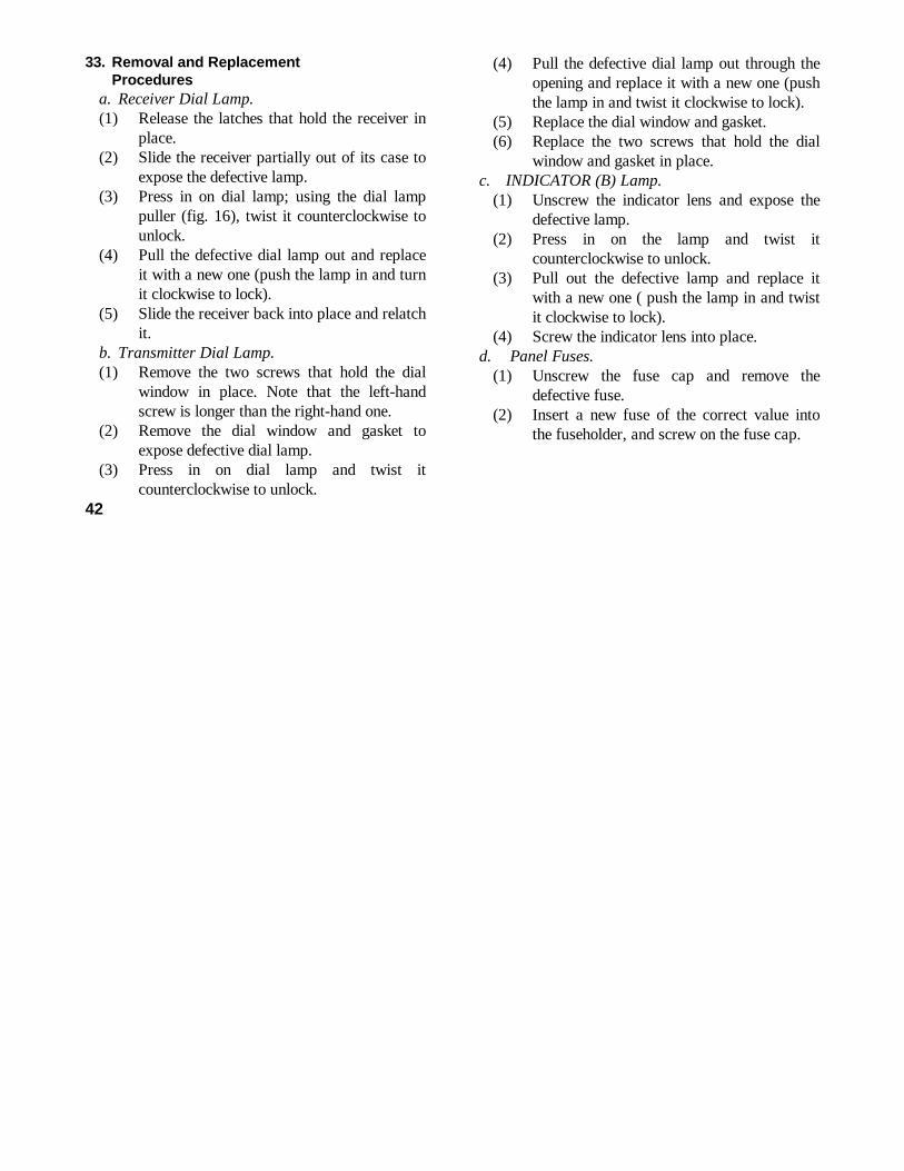
33. Removal and ReplacementProcedures
a. Receiver Dial Lamp.(1) Release the latches that hold the receiver in
place.(2) Slide the receiver partially out of its case to
expose the defective lamp.(3) Press in on dial lamp; using the dial lamp
puller (fig. 16), twist it counterclockwise tounlock.
(4) Pull the defective dial lamp out and replaceit with a new one (push the lamp in and turnit clockwise to lock).
(5) Slide the receiver back into place and relatchit.
b. Transmitter Dial Lamp.(1) Remove the two screws that hold the dial
window in place. Note that the left-handscrew is longer than the right-hand one.
(2) Remove the dial window and gasket toexpose defective dial lamp.
(3) Press in on dial lamp and twist itcounterclockwise to unlock.
(4) Pull the defective dial lamp out through theopening and replace it with a new one (pushthe lamp in and twist it clockwise to lock).
(5) Replace the dial window and gasket.(6) Replace the two screws that hold the dial
window and gasket in place.c. INDICATOR (B) Lamp.
(1) Unscrew the indicator lens and expose thedefective lamp.
(2) Press in on the lamp and twist itcounterclockwise to unlock.
(3) Pull out the defective lamp and replace itwith a new one ( push the lamp in and twistit clockwise to lock).
(4) Screw the indicator lens into place.d. Panel Fuses.
(1) Unscrew the fuse cap and remove thedefective fuse.
(2) Insert a new fuse of the correct value intothe fuseholder, and screw on the fuse cap.
42

CHAPTER 4AUXILIARY EQUIPMENT
34. Purpose of Auxiliary EquipmentPower Unit PE-162-(*) (pare 35) and Power
Supply PP-327(*)/GRC-9Y (pare 36) are used asauxiliary equipment to extend the ground (man-transportable) operation of the AN/GRC-87 forsemipermanent installations.
35. Power Unit PE-162-(*)When required, this power unit can be used in
place of Generator, Direct Current G -43/G inground (man-transportable) operations. The PE-162-(*) is a lightweight, electric gener-
ator (gasoline-driven type) that is manually started.It is designed to supply 7- and 550- do at a poweroutput of 150 watts. For additional information andoperating instructions refer to TM 11-971.
36. Power Supply PP-327 (*)/GRC-9YWhen required, this power supply is used in place
of Generator, Direct Current G 43/G when an inputsource 115- or 230-volts ac is available for ground(man-transportable) operations. For additionalinformation and operating instructions refer to TM11-5070.
CHAPTER 5DEMOLITION OF MATERIEL TO PREVENT ENEMY USE
37. Authority for DemolitionDemolition of the equipment will be accomplished
only upon the order of the commander. Thedestruction procedures outlined in paragraph 35 willbe used to prevent further use of the equipment.
38. Methods of DestructionUse any of the following methods to destroy the
equipment.a. Smash. Smash the controls, tubes, coils,
switches, capacitors, and transformers; use
axes, handaxes, pickaxes, hammers, or crowbars.b. Cut. Cut the connecting cables; use axes,
handaxes, or machetes.c.Burn. Burn cords and technical manuals; use
gasoline, kerosene, oil, flamethrowers, or incendiarygrenades.
d. Bend. Bend panel and cabinet.e.Explode. If explosives are necessary, use
firearms, grenades, or TNT.f. Dispose. Bury or scatter the destroyed parts in
slit trenches, foxholes, or throw them into streams.
43

APPENDIX IREFERENCES
DA PAM 310-4 Index of Technical Manuals, Technical Bulletins, Lubrication Orders,and Modification Work Orders.
SB 11-182 Dynamotor power supply DY-105( )/GRC-9X.
SB 11-265 Replacement of Battery BA-48 by Battery BA-317/U.
SB 11-474 Cross-Reference Type Number to Federal Stock Number.
SB 11-501 Conversion of Radio Set AN/GRC-9 (*) to Radio Set AN/GRC-87(ground version) and AN/GRC-9 (*) to Radio Set AN/GRC-87
TB SIG 109 Headset H-16/U.
TB SIG 330 Microphone M-52/U and M-52A/U.
TM 10-500-10-2-3 Air delivery of supplies and equipment: Rigging AN/GRC-87 andAN/VRC-18 Radio Set mounted in M38A1 l/4-ton utility truck oncombat-expendable platform.
TM10-500-1OA-3 Air delivery of supplies and equipment: Rigging AN/GRC-87 andAN/VRC-18 Radio Sets mounted in M38A1 i/4-ton utility truck.
TM11-971 Power Units PE-162-A, PE-162-B, and PE-162-C.
TM 11-5070 Power Supplies PP-327/GRC-9Y, PP-327A/GRC-9Y, and PP-327B/GRC-9Y.
TM 11-5122 Direct Current Generator G-43/G.
TM 11-5820-453-20 Organizational Maintenance Manual: Radio Set AN/GRC-87; AN/VRC-34.
TM 11-5820-79-12P Operator and Organizational Maintenance Repair Parts and SpecialTools List and Maintenance Allocation Chart: Mast Base MP-65,MP-65A, and MP-65B.
TM 11-5965-212-15P Operator, Organizational, Field and Depot Maintenance Repair Partsand Special Tools List and Maintenance Allocation Chart: Microphone M-52/U and M-52A/U.
TM 11-5965-213-15P Maintenance Repair Parts and Special Tools List and MaintenanceAllocation Chart for Permanent Magnet Loudspeaker LS-203/U (in-cluding LS-7 and LS-7A).
TM 11-5965-267-15P Operator, Organizational, Field and Depot Maintenance Repair Partsand Special Tools List: Headset, Electrical H-16/U.
TM 38-750 The Army Equipment Record System and Procedures.
44

APPENDIX IIBASIC ISSUE ITEMS LIST
Section I. INTRODUCTION1. General
a. This appendix lists items supplied for initial operationand for running spares. The list includes tools, parts, andmaterial issued as part of the major end item. The listincludes all items authorized for basic operatormaintenance of the equipment. End items of equipmentare issued on the basis of allowances prescribed inequipment authorization tables and other documents thatare a basis for requisitioning.
b. Columns are as follows:(1) Source, maintenance, and recoverability code.
Not used.(2) Federal stock number. This column lists the
11-digit Federal stock number.(3) Designation by model. The dagger (I) indicates
the equipment in which the part is used andfurther, by its position, designates the quantityused in each equipment where the quantityvaries
(4) Description. Nomenclature or the standard itemname and brief identifying data for each itemare listed in this column. When requisitioning,enter the nomenclature and description.
(5) Unit of issue. The unit of issue is each unlessotherwise indicated and is the supply term bywhich the in dividual item is counted forprocurement, storage, requisitioning,allowances, and issue purposes.
(6) Expendability. Nonexpendable items areindicated by NX.
(7) Quantity authorized. Under "ItemsComprising an Operable Equipment," thecolumn lists the quantity of itemssupplied for the initial operation of theequipment. Under "Running SpareItems" the quantities listed are thoseissued initially With the equipment asspare parts. The quantities areauthorized to be kept on hand by theoperator for maintenance of theequipment.
(8) Illustrations. The Item No. column lists thereference designations that appear onthe part in the equipment. These samedesignations are also used on anyillustrations of the equipment. Thenumbers in the Figure No. column referto the illustrations where the part isshown.
2. BatteriesDry batteries shown are used with the equipment but
are not considered part of the equipment. They will not bepreshipped automatically but are to be requisitioned inquantities necessary for the particular organization, inaccordance with SB 11-6.
45

SECTION II FUNCTIONAL PARTS LIST (AN/GRC-87) (AN/VRC-34)
ILLUSTRATIONDESIGNATION UNIT QTY
FEDERAL BY DESCRIPTION OF EXP AUTH FIGURE ITEMSTOCK NUMBER MODEL ISSUE NO NO.
5820-543-1997 RADIO SET AN/GRC-87: gound version, 2 to 12 mc frequency range; NX3 bands; 6 channels
5820-543-1996 RADIO SET AN/VRC-34: vehicular version, 2 to 12 mc frequency NXrange; 3 bands, 6 channels
ITEMS COMPRISING AN OPERABLE EQUIPMENT
NOTE: MODEL COLUMN 1 REFERS TO AN/GRC-87, COLUMN 2 REFERS TOAN/GRC-34
Ord thru AGC TECHNICAL MANUAL TM 11-5820-453-10 25820-243-0432 ANTENNA, AT-101/GRC-9; fixed type; 8 sect; 4.3 to 12 mc freq NX 1
range; 107 ft 6 in lg o/a (NOTE: stored on RL-29 when not inuse) (Not installed)
5820-243-1413 ANTENNA AT-102/GRC-9; fixed type 9 sect; 2 to 4.3 c; 137 ft lg NX 1o/a w/provisions for shorting as required (NOTE: stored on RL-29 when not in use) (Not installed) (Not mounted)
5820-308-5817 BAG CW-140/GRC-9; for carrying Receiver and TransmitterRT-77/GRC-9 wp canvas; 14 in lg x 14 in x 16 in h (Not installed 1(Not mounted)
5820-690-8541 BAG, COTTON DUCK, CW-419/GRC-9 65-1/2 in lg by 33 in w w/approx NX 1dim opened; 4 flap type and fixed type pockets; Sig dwg SC-DL-31963 (Note: Replaces Roll BG-174 in AN/GRC-9) (Not installed)(Not mounted)
6115-709-0463 BAG, CW-420/G: for generator: 15-1/2 in lg x 6-1/2 in w x 11-3/4 1in h o/a olive drab water repellent Sig dwg No . SC DL-17336 (Notmounted
6135-669-6632 BATTERY, DRY BA-317/U: NOTE: Stored in Bag CW-140/GRC-9 (Not 1installed)
OR6135-120-1007 BRACKET, DRY BA-48: NOTE: Stored in Bag CW-140/GRC-9 15820-129-9666 BRACKET, FT-515: used to mount insulator in 127 6-1/2 in lg x 1 in 1 5
wd x 1/8 in thk; Sig dwg SC-D-19573 NOTE; Stored in accessoriesBag (Not installed)
OR46 AN/GRC-87 AN/VRC-34 2

ILLUSTRATIONDESIGNATION UNIT QTY
FEDERAL BY DESCRIPTION OF EXP AUTH FIGURE ITEMSTOCK NUMBER MODEL ISSUE NO. NO.
AN/GRC-87 AND AN/VRC-34 (CONTINUED)
5995-196-9564 CORD ASSEMBLY CD-307-B: (65 IN) 22 awg; 5 ft 10-13/32 in lg o/a 1MIL-C-3884; type ne COS-2(22) MIL-STD MS-35760 Note: Stored inaccessories bag (Not installed)
5995-164-6457 CORD ASSEMBLY, CD-106 (7 ft): MIL-C-3432 Sig dwg SC-D-22829 2Note: Stored in accessories bag (Not installed) 1
5995-162-6946 CORD ASSEMBLY, CD-119 (36 in): 18 awg; 3 ft 2 in lg o/a ; Sig dwg 1SC-C-26551 Note: Stored in accessories bag (Not installed)(Not mounted)
5820-237-7321 COUNTERPOISE CP-12: radial type; Sig dwg SC-D-1038F: (Note; NX 1Stored on RL-29 when not in use) (Not installed)
5820-224-4885 COUNTERPOISE CP-13: radial type Sig dwg SC-D-1038; (Note: Stored NX 1on RL-29 when not in ue) (Not installed)
5965-243-0207 COVER, MICROPHONE CW-292-W: 1.218 in lg x 0.671 in h 0.605 in 1dia; polethylene spec MIL-H_11190 Note: Stored in accessoriesbag
6125-635-3770 DYNAMOTOR, POWER SUPPLY DY-105/GRC-9X, DY-105A/GRC-9X, NX 1DY-105B/GRC-9X; for 24 v DC input operation only; Sig dwgSC-DL-177015 Note: For 6v or 12V intallation substitute Dyna-motor Power Supply DY-88/GRC-9 for Dynamotor Power SupplyDY-105/GRC-9X, DY-105A/GRC-9X, DY-105B/GRC-9X (Not mounted)
6125-321-5928 DYNAMOTOR, POWER SUPPLY DY-88/GRC-9: for 6v, 12v or 24v, DC in NX 1put operation: Note: for 6v or 12 v installation may be issuedin lieu of DY-105/GRC-9X when DY-105A/GRC-9X is not availablefor issue (Not installed) (Not mounted)
6115-501-0611 GENERATOR, G-43/G: hand gen; power output, 425 v at 115 ma, 105v NX 1at 32 ma, 6.3 v at 2.5 amp, 1.4v at 0.465 amp, HV-8% variance,LV 2T variance, 50-70 rpm; Sig dwg SM-D-202177 Note: Stored inBac CW-420/G when not in use (Not installed)
AN/GRC-87; AN/VRC-3447

ILLUSTRATIONDESIGNATION UNIT QTY
FEDERAL BY DESCRIPTION OF EXP AUTH FIGURE ITEMSTOCK NUMBER MODEL ISSUE NO. NO. NO.
AN/GRC-87; AN/VRC-34 (CONTINUED)
5975-197-4252 GUY GY-12: ant mast guy; 20 ft lg; Sig dwg SC-D-1072 NOTE: 1Stored in accessories bag (Not installed)
5975-199-5072 GUY GY-42: used w/mast sect; 2 lgth 20 ft lg; Sig dwg SC-D-15884 1NOTE: Stored in accessories bag (Not installed)
5820-493-9361 HALYARD, M-378: braided cotton; 9/16 in dia, 80 ft lg; NOTE: 1stored in accessories bag (Not installed)
5820-408-3197 HALYARD M-379: in braided cotton, 9/64 in dia 10 ft 6 in lg; Sig 1dwg SC-C-35483 NOTE: Stored in accessories bag (Not installed)
5965-162-7931 HEADSET, ELECTRICAL H-16/U magnetic, 8000 ohm impedance, Sig dwg NX 1SC-D-14618 NOTE: Stored in accessories bag (Not installed)
5970-227-8226 INSULATOR IN-127: cylindrical; molded phenolic; 12-21/32 in lg; 1Sig dwg SC-DL-35528 NOTE: Stored in accessories bag (Notinstalled)
5970-197-3576 INSULATOR, STRAIN IN-86: Sig dwg SC-D-1134 NOTE: Sto red in accessories 1bag (Not installed)
5805-171-3370 KEY J-45: 5-1/2 in lg x 4-1/4 in wd x 6 in h Sig dwg SC-D-1059 1NOTE: Stored in accessories bag (Not installed)
5965-280-3800 LOUDSPEAKER LS-203/U: LS-7A; blast proof type; PM field, 8 ohm NX 1voice coil, Sig dwg SC-DL-6420 NOTE: Stored in accessories bag(Not installed)
5820-503-2953 MAST BASE MP-65-B: Sig dwg SC-D-20718 NOTE: Stored in accessories NX 1bag (Not installed)
5820-199-8131 MAST SECTION MS-116A: 39-1/2 in lg x 0.393 dia; Sig SC-DL-100588- 3 23MS116A NOTE: Stored in accessories bag CW-419/G (Not installed)
5820-199-8843 MAST SECTION MS-117A: 39-1/2 in lg x 0373 dia; Sig dwg SC-D-12521 1 23NOTE: Stored in accessories bag CW-419/G (Not installed)
5820-199-8841 MAST SECTION MS-118A: 39-1/2 in x 0.246 in dia; Sig dwg 1 23SC-D-12521 NOTE: Stored in accessories bag CW-419/G (Not installed)
AN/GRC-87; AN/VRC-34
48

ILLUSTRATIONDESIGNATION UNIT QTY
FEDERAL BY DESCRIPTION OF EXP AUTH FIGURE ITEMSTOCK NUMBER MODEL ISSUE NO. NO. NO.
AN/GRC-87; AN/VRC-34 (CONTINUED)6625-701-9103 METER FIELD STRENGTH ME-61/GRC: 6 in lg x 5-1/2 in w x 5 in 1 C3
h o/a NOTE: Stored in accessories bag (Not installed)5965-646-4678 MICROPHONE, CARBON M-52/U: 40 to 1000 ohms at 1000 cps: MIL NX 1
Spec No. MIL-M-11193B w/anend No. 4. NOTE: Stored inaccessories bag (Not installed)
5820-128-2207 MOUNTING MT-350/GRC-9: 16-5/8 in lg x 11-9/16 in w x 1-5/8 in 1h; Sig dwg SC-C-20701 (Not installed)
5820-196-9041 RECEIVER-TRANSMITTER RT-77/GRC-9, RT-77A/GRC-9: vehicular NX 1transportable; xmtr output 25 w cw, 8.5 phone; 2 to 12 mc in3 bands; 16-1/2 in lg x 12-1/2 in w x 8 in h o/a; Sig SpecNo. 271-3213; Sig dwg SC-DL-57596 (Not installed)
8130-355-7616 REEL RL-28: for Guy-11 Guy 12; 6-1/2 in lg x 2-3/4 in w x 10.747 in thk; Sig dwg SC-D-1064 NOTE: Stored in accessoriesbag (Not installed)
5820-030-2969 REEL RL-29: for sig counterpoise CP-12 and CP-13; 11-1/2 in lg 3x 5-1/2 in w Sig dwg SC-D-1040 NOTE: Stored in accessoriesbag (Not installed)
4020-240-2145 ROPE RP-5; cotton core, 12 strands 3/16 in dia 255 lbs min ft 25braking strength; NOTE: Stored in accessories bag (Notinstalled)
4130-223-4612 STAKE, GUY GP-27B: anchors guy; 7-9/16 in lg x 5/16 in dia 4Sig dwg No. SC-D-1063 NOTE: Stored in accessories bag(Not installed)
6145-160-5114 WIRE W-128: single No. 14 AWG cond, stranded, forty-one ft 10No. 30 AWG strands NOTE: Stored in accessories bag(Not installed)
GROUP IDYNAMOTOR, POWER SUPPLY DY-88/GRC-9
DYNAMOTOR, POWER SUPPLY DY-88/GRC-9 (BASIC COMPONENT) (Not NX 1 installed)
AN/GRC-87; AN/VRC- 49

DESIGNATION UNIT QTYFEDERAL BY DESCRIPTION OF EXP AUTH FIGURE ITEM
STOCK NUMBER MODEL ISSUE NO. NO. NO.
AN/GRC-87; AN/VRC-34 (continue)5995-280-4264 CABLE ASSEMBLY, SPECIAL PURPOSE, ELECTRICAL CX-2031A/U (8 ft) 1
uses cord CO-212 (Not installed)6125-219-9988 HARDWARE KIT: for mtg DY-88/GRC-9 to vehicle (in cloth bag) 1
GROUP IIDYNAMOTOR, POWER SUPPLY
DY-105/GRC-9X; DY-105A/GRC-9; DY-105B/GRC-9XDYNAMOTOR, POWER SUPPLY DY-105/GRC-9X; DY-105A/GRC-9X; DY-105B/ 1
GRC-9X; (BASIC COMPONENT) (Not installed)HARDWARE KIT:f/mtg Dynamotor-Power Supply tp vehicle; c/o 1
lockwashers, nuts, bolts in cloth bag: Amitool No. 25095(in cloth bag)
5995-280-4264 CABLE ASSEMBLY SPECIAL PURPOSE, ELECTRICAL: CX-2031A/U: (8 ft) 1uses cordage CO-212 (Not installed)
GROUP IIIRECEIVER TRANSMITTER RT-77/GRC-9; RT-77A/GRC-9
5995-170-6877 CABLE ASSEMBLY SPECIAL PURPOSE ELECTRICAL: interconnects 1Rec-xmtr; 23-1/8 in 1g approx SC-C-35501(Installed in equip)
5820-545-8234 CABINET houses rec and xmtr; 15-1/2 in 1g x 10-1/2 in wd 1x 4-9/32 in d approx o/a Sig dwg SC-D-35818 (Not installed)
6135-271-0407 BATTERY DRY, BA-1293/u: grid bias fv6 p/o rec (Not installed) 1(Not mounted)
5820-691-2059 PANEL, COVER CW-109/GRC: water tight metal covr f/RT-77(*)/GRC-9; 111-1/2 in 1g x 16-1/2in wd w/3 in fl (Mounted in equip)
5820-537-3904 RECEIVER, RADIO: part of RT-77/GRC-9; RT-77A/GRC-9; 10-1/2 IN 1G 1x 5-1/8 in h x 6-1/2 in d o/a (installed in case)
5825-309-3200 TRANSMITTER, RADIO: part of RT-77/GRC-9; RT-77A/GRC-9; 10-5/5/8 in 11g x 10-3/8 in wd x 6-1/2 in d o/a (installed in case)
AN/GRC-87; AN/VRC-3450

ILLUSTRATIONDESIGNATION UNIT QTY
FEDERAL BY DESCRIPTION OF EXP AUTH FIGURE ITEMSTOCK NUMBER MODEL NO. NO.
AN/GRC-87; AN/VRC-34 (continued)RUNNING SPARE ITEMS
RADIO SET AN/GRC-87 ABD AB/VRC-34NOTE: Model Column refers to AN/GRC-87; Column 2 refers to
AN/VRC-345820-243-0432 ANTENNA, AT-101/GRC-9: fixed type; 8 sect; 4.3 to 12 mc freq NX 1
range; 107 ft 6 in 1g o / a; NOTE: Stored in bag CS-4195970-197-3576 INSULATOR, STRAIN IN-86: Sg dwg SC-D- 1134 NOTE: Stored in 2
Bag CW-419/G5820-199-8131 MAST SECTION MS-1164: 39 ½ in 1g x 0.393 dia; Sig dwg 3
SC-DL-100588 NOTE: Stored in bag CW-419/G5820-199-8843 MAST SECTION MS-117A: 39 ½ in 1g x 0373 dia; Sig dwg No. 1
SC-D-12521 NOTE: Stored in bag CW-419/G5820-199-8841 MAST SECTION MS-118a 39 ½ in 1g x 0.246 in dia; Sig dwg 1
SC-D-12521 NOTE: Stored in bag CW-419/GDYNAMOTOR, POWER SUPPLY
DY-88/GRC-95920-280-8604 FUSE, CARTRIDGE: 2 amp MIL type F08G2ROOB; use for 12v or v24 5
operation only (NOTE: Stored in spare fuse holder on front panel)OR
5920-280-3171 FUSE, CARTRIDGE: 5 AMP TYPE FO8D5ROOA (use for 6 volt operation only) 3(NOTE: Stored in spare fuse holder on front panel)
5920-280-3157 FUSE, CARTRIDGE: 10 amp 32v; Buss type MDR-10-D-E (NOTE: 3Stored in spare fuse holder on front panel)
5920-399-7760 FUSE, CARTRIDGE: 20 amp 32v; Buss type MDR-20-DE (NOTE: Stored 3in spare fuse holder on front panel)
5920-280-3177 FUSE, CARTRIDGE: 30 amp, 32v; Buss type MDR-30-D-E (NOTE: Stored inspare fuse holder on front panel)
AN/GRC-87; AN/VRC-34 51

ILLUSTRATIONDESIGNATION UNIT QTY
FEDERAL BY DESCRIPTION OF EXP AUTH FIGURE ITEMSTOCK NUMBER MODEL ABILITY NO. NO.
AN/GRC-87; AN/VRC-34 (continued)DYNAMOTOR, POWER SUPPLY
DY-105/GRC-9X; DY-105A/GRC-9X; DY-105B/GRC-9X5920142-7346 FUSE, CARTRIDGE: 3 amp; Buss type AGU-3; (NOTE: Stored in spare st 4
fuse holder on frt panel) (Not mounted)5920-280-3157 FUSE, CARTRIDGE: 10 amp MIL type FO7A10ROB: (NOTE: Stored in 4
spare fuse holder mtd on frt panel) (Not mounted)RECEIVER, RADIO
(FSN 5820-537-3904)NOTE: The following item is stored in Box BX-53-D
6240-155-8683 LAMP, INCANDESCENT: 2V, 0.06 ampl min bayonet base; GE No. S-49 1(Not mounted)
TRANSMITTER, RADIO(FSN 5825-309-3200)
NOTE: The following items are stored in Box BX-53-D6240-155-8683 LAMP, INDANDESCENT: 2v, 0.06 amp min bayonet base; GE S49 1
(Not mounted)6240-299-6970 LAMP, GLOW: GE No. NE-47 (Not mounted) 1
52 AN/GRC-87; AN/VRC-34

By Order of the Secretary of the Army: EARLE G. WHEELER,General, United States Army,
Official: Chief of Staff.J. C. LAMBERT,Major General, United States Army,The Adjutant General.
Distribution:Active Army: USA Elet Mat Agcy (25) 5-501 11-167
DASA (6) Chicago Proc Dist (1) 5-600 11-500 (AA-AC)USASA (2) USASCC (4) 5-605 (RM-RU)CNGB (1) USARCARIB Sig Agcy (1) 5-627 11-557CofEngrs (1) Sig Fld Maint Shops (3) 6-401 11-587TSG (1) CofSptsS (1) 6-501 11-592CSigO (7) Def Comms Agcy (1) 6-535 11-597CofT (1) Units org under fol TOE: 6-536 11-608USA CD Agcy (1) (2 copies each UNOINDC) 6-537 17USCONARC (5) 1-7 7 17-51USAMC (5) 1-17 7-31 19-2USAECOM (5) 1-67 7-32 19-35USAMICOM (4) 1-127 8-15 19-36ARADCOM (2) 1-137 8-16 19-37ARADCOM Rgn (2) 5-5 8-17 19-55OS Maj Comd (3) 5-6 8-18 19-56OS Base Comd (2) 5-15 8-35 19-57LOGCOMD (2) 5-16 8-36 29-1MDW (1) 5-17 8-137 29-7Armies (2) 5-25 9-9 29-21Corps (2) 5-26 9-12 29-56USA Corps (3) 5-35 9-47 33-105Instls (2) except 5-36 9-65 33-106Fort Monmouth (63) 5-37 9-66 33-107USATC AD (2) 5-38 9-86 37USATC Armor (2) 5-45 9-87 39-51USATC Engr (2) 5-46 9-117 44-2USATC Inf (2) 5-47 9-197 44-12USASTC (2) 5-49 9-227 44-57Svc Colleges (2) 5-52 9-500 (AA-AC) 44-235Br Svc Sch (2) 5-54 10-22 44-236
CENDEP (OS) (2) 5-97 10-202 44-237Sig Dep (OS) (12) 5-112 10-206 44-435Army Dep (2) except 5-114 10-445 44-436
Fort Worth Army Dep (8) 5-115 10-446 44-437Lexington Army Dep (12) 5-116 10-449 44-445Sacramento Army Dep (28) 5-117 10-536 44-446Tobyhanna Army Dep (12) 5-118 11-5 44-447
Sig Sec. GENDEP (OS) (5) 5-124 11-7 44-448USA Elct RD Actv (Ft Huachuca)(2) 5-145 11-16 44-500 (AA-AB)USA Elct RD Actv (White Sands)(13) 5-146 11-55 44-535
WRAMC (1) 5-155 11-57 44-536Army Pictorial Cen (2) 5-156 11-96 44-537USA MOB Spt. Cen (1) 5-237 11-97 44-545Trans Tm1 Comd (1) 5-278 11-98 44-546Army Tm1 (1) 5-327 11-117 44-547POE (1) 5-278 11-155 44-548USAOSA (1) 5-327 11-157 52-2AFIP (1) 5-348 11-165 57AMS (1) 5-500 (AA-AD) 11-166

NG: State AG (3); Units-Same as Active Army except allowance is one copy for each unit. USAR: None.For explanation of abbreviations used, see AR 320-50.


THE METRIC SYSTEM AND EQUIVALENTS

PIN: 018733-002