Embed Size (px)
Citation preview

OPERATOR’S MANUAL
Baker ChemGARD
General Purpose Chemical Fume Hood
The Baker Company
This manual contains information regarding installation, operation, maintenance and spare parts. We recommend that it be kept near the fume hood for ready reference.

THE BAKER COMPANY
INTRODUCTION AND WELCOME
It is a pleasure to welcome you to the growing number of customers who own and operate Baker Chemical fume hoods. As the pioneer in the design and manufacture of laminar flow clean benches and Biological safety cabinets, The Baker Company is the recognized leader in reliable contamination control. Baker people take special pride in providing a fume hood which is designed for maximun performance. Your new ChemGARD unit has a number of remarkable features. Among them, the angled side- entrance, airfoil and radiused worksurface deliver air to the work area efficiently. This minimizes turbulence, and the continous bypass design substantially reduces the “roll effect.” A unit equipped with a combination horizontal/vertical sash provides a protective physical barrier while delivering a 50% energy savings. A conventional vertical sash is also available. The ChemGARD unit has been engineered for unparalleled safetuy, performance and durability. Tested to the performance standards established by ACGIH using the ASHRAE 110-1995 method, your ChemGARD hood will provide superior performance, simpler maintenance and lower life cycle cost. Your ChemGARD unit is designed for both safety and value. You will find your ChemGARD fume hood suitable for general laboratory use. It is designed to provide the efficient removal of unwanted fumes and airborne particles from a workspace, when incorporated into an appropriate exhaust system. It is not designed to function as a perchloric acid or radioisotope hood, or any other “special” purpose hood. Your safety officer, industrial hygienist, and facilities engineering manager should approve its use, define the required face velocity, verify and maintain the proper exhaust for the end-user’s application. We recommend that this manual be kept near your fume hood for convenient reference by operators and Qualified maintenance personnel. If you have any questions about the use or care of your new ChemGARD fume hood, please do not hesitate to contact our Customer Service Department for assistance. Sincerely, Dennis Eagleson President & CEO The Baker Company, Inc. P.O. Drawer E, Sanford, Maine 04073 (207) 324-8773 1-800-992-2537 FAX (207) 324-3869 “Creating immaculate atmospheres

i
TABLE OF CONTENTS
Section I – Function and Description Page I Aerodynamic features I About the airflow in the ChemGARD unit 2 The combination sash 3 Worksurface 3 One-piece sidewall construction 3 Rear baffle 3 Service fixtures 4 Light box 4 Switches 4 Velocity monitor/alarm 4 Performance assurance 5 Specifications 6 Section II – Preparing Your ChemGARD Hood for use 7 Checking the fume hood on arrival 7 Location within the laboratory 7 Installing the fume hood 7 Exhaust requirements 8 Section III – Using the Fume Hood Properly 10 Positioning the sash 10 Using the Airwatch II face velocity monitor 11 Working in the hood 12 Laboratory environment 12 Safety plan 12

ii
Using ancillary equipment 13 Work practices for laboratory hoods 13 Other precautions 14 Section IV – On-Site Checks and Maintenance Procedures 15 Determining the face velocity 15 Calibrating the Airwatch II unit 15 Setting the alarm set-point 16 Setting DIP switch options 17 Cleaning the airflow monitor probe 17 Hood material – care and cleaning 18 Service areas 18 Section V – Appendix 20 Glossary 20 Bibliography 22 Wiring diagram 23 Chemical resistance chart 24 Replacement parts list 26 Purchase specifications 27 Warranty 28 List of Figures Figure 1 Airflow in ChemGARD uinit Page 2 Figure 2 Dimensional Drawing 9 Figure 3 Control Panel – Airwatch II Monitor 11 Figure 4 Wiring Diagram 23

ii
1 – FUNCTION AND DESCRIPTION OF THE CHEMGARD FUME HOOD Your ChemGARD fume hood is a general purpose, continous bypass laboratory fume hood. It is designed to efficiently remove unwanted fumes and airborne particulate from the work space, providing optimum personnel protecttion. It is to be used in combination with an appropriateexhaust system, as defined and approved by your safety officer and facilities engineering manager. NOTE: This unit is not designed to function as a perchloris acid, radioisotope or any “special” purpose hood. Access to the workspace is provied through a front opening equipped with a safety plate glass sash.Your unit may have combination horizontal/vertical sash, or a sash which can move in the vertical direction only. The combination sash provides the user complete access to the work area with a minimum amount of exposure. In addition to full vertical travel, the combination sash contains 12” wide safety plate glass panels which can move horizontally. The combination sash provides increased operator safety and energy savings. (For a complete description of the combination sash and the exhaust requirements, see Section II.) Aerodynamic features Proper fume hood performance is determined by precise airflow control through the work area. The unit is designed to draw noxious vapors and gases away from the breathing zone and into the exhaust system. A streamlined, unobstructed design delivers a uniform airflow. This minimizes backdrafts, turbulence and eddy currents. The ChemGARD unit has been engineering to
include several aerodynamic features to ensure unparalleled performanace: Radiused worksurface – The leading edge of the worksurface has a 1” radius to provide smooth airflow beneath the worksurface airfoil. Worksurface airfoil – The radiused airfoil is positioned 2” above the worksurface, and the worksurface undercut by 2”. This provides unrestricted air flow. The airfoil is made of corrosion-resistant 14 gauge type 304 stainless steel. The leading edge is flush with the worksurface elevation, providing a barrier to splashes. Bell mouth inlet – The sidewall is fabricated so that it simulates a “bell mouth” inlet into the hood. This Minimizes air turbulence as it enters the unit. Sash frame – The bottom frame member incorporates a ½” radius into an aerodynamic shape. The side members are parallel to the surface of the sidewalls. Again, this minimizes air turbulence. Combination horizontal’vertical sash - The sash design allows full access tothe hood while requiring approximately half the amount of conditioned exhaust air. (This valve is compared with sashes which move vertically only at equivalent intake velocities.)

Continuous bypass – The continuous flow of air into the hood behind the sash results in decreased concentrations of contaminants at the hood-user interface. The bypass design creates this performance enhancing feature regsrgless of sash position. (For more information, see Bibliogrphy reference #12 in the Appendix.) About the airflow in the ChemGARD unit
The exhaust system to which the fume hood is connected provides the energy which moves the air. The fume hood design directs the flow of air in an efficient manner to contain fumes and gases. The pressure differential between the laboratory and the hood interior creates a flow of air into the hood. The anount of turbulence created as air flows into a hood depends on several factors, one of which is the shape of the inlet. A “bell mouth” curve closely describes the path of the airflow as it enters the hood. Inlet designs which simulate this shape mimimize turbulence. The inlet on the ChemGARD hood is designed with a 40° included angle. This simulates the ideal “bell mouth” shape for the inlet. As air enters a hood along the worksurface, it tends to lift away from the surface. This can cause an eddy current or backflow to occur just inside the entrance. The ChemGARD hood has a 1” radius on the front edge of the epoxy resin top to minimize this turbulence. An airfoil that simulates the bell mouth shape is
positioned 2” above the worksurface, and overhangs the front edge of the worksurface by 2”. The purpose of this airfoil is to direct airflow across the worksurface, capturing fumes in the area where they are frequently generated. Airflow beneath the bottom edge of the sash has also been directed to enter as smoothly as possible. The bottom frame member has a ½ “ radius to provide a smooth inlet when the sash is opened vertically.The side frame members are angled 20° to be flush with the sidewalls, providing a smooth inlet for horizontal openings. Once the air has entered the hood in an aerodynamic fashion, it is directed out of the hood in a manner which minimizes the “roll effect.” The roll effect causes the fumes and vapors to linger in the work area. In the ChemGARD unit, the rear baffles are designed to direct the air out of the hood to minimize the roll effect. The rear baffles create slots at the bottom rear and top center of the hood. All of the airflow from the hood is exhausted through these slots. The bottom slot creates flow directly across the worksurface, entraining fumes from spills, open beakers and flasks. The top slot ventilates the top of the hood minimizing fume concentrations.
2

In addition to the turbulence that may be created when air flows into a hood along the walls and worksurface (discussed above), more turbulence is created when air flows past an obstruction. A negative pressure void forms in the space behind the obstruction. The air tries to fill this void, and this creates eddy currents. This happens in the case of the sash on a fume hood. Air flowing under the sash (when it is opened vertically) or around the sash (when opened horizontally) can “roll” into the low pressure space behind the sash. In the ChemGARD unit, the continuous bypass design allows, the room air to create a barrier between the roll and operator in the vertical sash mode. In the horizontal mode, room air directly enters the roll behind the horizontal panels, thereby reducing concentrations. The special aerodynamic design of the ChemGARD unit decreases the concentration of fumes in the hood while increasing the unit’s capture efficiency. This result is maximized protection to the hood user. The combination sash A ChemGard fume hood can be configured with a combination sash which moves both horizontally and vertically, or a sash which opens vertically only. The combination sash allows for full vertical travel. It includes 12” wide panels which are made os safety plate glass. These are suspended on ball bearings, and slide horizontally to allow access to the work area. This configuration provides a physical barier between the user and the work area, minimizing exposure and enhancing safety. The combination sash results in significant energy savings. The design of the combination sash requires 50% less exhaust
conditioned air than “vertical only” sashes. The combination sash allows the unit to maintain the proper face velocity without drawing in excessive amounts of room air. This is possible because the sliding horizontal panels control the size of the opening to the work area, reducing the draw on laboratory room air. NOTE: In order to realize the energy savings, the exhaust system should provide the correct exhaust when the sash is completely open in the horizontal direction, while closed vertically. For exhaust requirments, see Section II. Worksurface The moled epoxy resin worksurface offers excellent resistance to a broad range of chemicals. The ¼” dish in the worksurface serves to contain spills and define the work area. The dished area starts 6” behind the sash to encourage work to be performed away from the front opening. It stops 1” from the rear baffle to prevent the placement of equipment in an area that would restrict airflow up behind the back baffle. The leading edge of the worksurface has a 1” radius to provide a smooth airflow beneath the worksurface airfoil. One-piece sidewall construction The interior sidewall is constructed from one piece of 16 gauge type 304 stainless steel. The sash track is formed in the sidewalls providing a seamless hood which may be cleaned easily. The sidewall is shaped to simulate a “bell mouth” inlet to the hood and minimize turbulence.
3
Rear baffle The rear baffle is construced of 16 gauge type 304 stainless steel with an integral protective grill in the rear duct. This helps to prevent wipes or other material from being drawn into the exhaust duct. The rear baffle can be removed through the front access opening. The exhaust slots have fixed widths and require no adjustment. Service fixtures Color-coded service fixtures with convenient remote-control valves may be specified by the purchaser. One standard service fixture is provided on the ChemGARD unit, a generic fixture located on the right hand side 11” above the epoxy work surface. Up to seven additional fixtures (for a total of four per side) can be added including hosecocks or goosenecks for air, vacuum, DI/DW water, hot water, cold water and gas. The hosecock fixtures are located towards the front of the inside walls, with goosenacks located towards the back of the sidewall. Knock-outs are provided for easy upgradability if fixtures must be added. Other optional equipment can be added, including stainless steel cupsink, vacuum breakers, stainless steel grid storage racks, stainless steel shelf, stainless steel work surface and an aspirator. Please contact a Baker Company Custopmer Service Representative for more details on how to retrofit your ChemGARD unit. Light box A fluorescent light fixture is located above the top liner panel. The power switch is conveniently located in the control pad on the outside right front panel. The light enters the hood through a safety plate glass which
is gasketed for safe operation. This design enables easy access to the light box from the front of the unit to change the light bulbs. Switches The ChemGArd unit provides two 15 amp GFI (ground fault interrupter) duplex electrical outlets. An Auxiliary switch, rated at 20A @ 115 VAC; 10A @ 250 VAC is available for retrofitting auxiliary equipment (blowers, relays, controls, etc.). Each outlet has its own switch located externally on the control panel for safe control. The outlets are wired through a single 10A circuit breaker for overlaod protection. Velocity monitor/alarm Safety officers, safety protocols and government regulations often specify a minimum face velocity for a fume hood. This value may depend on the relative hazard associated with the chemical being used as well as other factors. When the exhaust flow rate is constant, the intake velocity varies as the sash position is changed. A problem with the in-house exhaust system can cause the face velocity to fall below a specified rate. To ensure that an operator is aware of any low-velocity situations, an aitflow monitor is essential. This ChemGARD unit includes the “Airwatch II” face velocity monitor. The monitor includes a sensor which is positioned in the continuous bypass duct. The negative pressure inside the hood causes the flow of air into the hood through both the front access opening and the bypass duct. The flow of air through the bypass duct is proportional to the flow through the front opening. Knowing this relationship exists, the intake velocity can be monitored by sensing the flow through the bypass.
4

The velocity is displayed on analog and digital readouts on the front coluum of the hood. A flashing red light, along with an audible alarm, warns the operator in the event of low or high velocity. (For instructions on calibrating the monitor/alarm, please see Section II). CAUTION: An alarm condition indicates a possible health risk to personnel. Appropriate action should be taken in the event of an alarm condition.
Performance assurance Each ChemGARD design has a certified copy of the ANSI/ASHRAE – 110 Fume Hood Performance Test, which is available upon request. The Baker Fume Hood Testing Laboratory combines ongoing research, new product development testing, computerized modeling and simulated environmental testing to ensure optimal designs which include the latest technology. The Baker commitment to quality stands behind every high performance ChemGard fume hood.
5

II – PREPARING YOUR CHEMGARD FUME HOOD FOR USE Checking the fume hood on arrival Upon receipt of your new ChemGARD Fume Hood, inspect the exterior of the crate and skid Any broken glass or other visible damage should be noted on the receiving slip and immediately reported to the delivering carrier. Remove the crate and inspect the unit. Remove the top cover of the crate first. Next, remove the boards from and back of the crate. Bend both ends of the crate outward away from the sides of the unit, and remove the front and rear blocking skids. Remove the wood blocking which supports the sash counter-weight located in the sidewall of the unit. If any concealed damage is found, it should be reported to the delivering carrier. The carrier will want an opportunity to inspect the damage. A claim for restitution should be filed within 45 days. If the optional base cabinet has been purchased along with your ChemGARD fume hood, remove the crate and inspect as outlined above. Certain parts of the hood have been removed and packed separately in order to ensure proper handling and to simplify movement of the unit into the building and room where the unit will be located. The three main parts are the fume hood, the worksurface and the base cabinet (if purchased) Any items packed separately are listed on the packing slips which accompany the unit. Please check all packing slips carefully to be sure that all items have been accounted for.
Location within the laboratory The performance of a fume hood is affected by air currents near the opening of the hood. The hood should be positioned so that performance is not affected by pedestrian traffic, changes in room air supply or other factors which upset the intake of air into the hood. Proper placement within the room is essential. For space requirements, see Fig. 2. It may be necessary to uncrtae and partially dissemble the units in order to get it into the building and/ or room. Installing the fume hood CAUTION: Installation should be done by qualified personnel as plumbing, electrical and HVAC work is required. 1. Uncrate all parts of the fume hood. Remove the Phillips-head wood screws which secure the the sidewalls of the hood to the skid. Remove the double-headed nails which attach the 2” x 8” lifting planks to the skid. 2. Determine the location where the fume hood will be installed. Set the base cabinet(s) in position A unit which is six feet long may have two 3” base cabinets which will need to be fastened to the epoxy worksurface). Leave space so hat plumbing can be fitted through the rear chaseway. (See Fig.2) Level the base cabinet (s) by adjusting the 1-1/2” leg levelers. 3. Using a fork truck or other lifting device, lift the hood. Use the 2” x 8” planks to support the weight of the hood.
6

4. Tilt the hood front to back and remove the 2” x 8” plank supporting front. NOTE: ChemGARD fume hoods are shipped with the sash counterweight installed and blocked. The standard 4,5,6 and 8 foot hood configuration includes a 40, 50, 60 and 80 lb weight respectively, located on the left-hand side of the unit. This weight should be taken into account whenpreparing to lift the hood onto the worksurface. 5. Remove the tape from the glass panels in
the sash assembly.
6. Service fixtures are plumbed to the center sidewall of the unit as shown in Fig. 2. Remove the side panels, and make any necessary plumbing connections.
4. The electrical requirements for the ChemGARD unit are listed in the Specifications in Section I. The electrical connections are made at terminals 1 and 2 in the electrical box located on the right side of the top of the unit. (See wiring diagram in Fig. 4) A copy of the wiring diagram for the hood is located next to the electrical box on the top of each unit.Overload protection for the duplex outlets is provided by the 10A self resettable circuit breaker. This is located on top of the unit in the left side electrical box. An auxiliary switch
contact, rated at 20 amp @ 115V (10A @ 250V) is also located on top of the unit in the electrical box on the left side of the unit. 8. After, all connections have been made, (gas, water, electrical, waste, etc),install the side panels. 9. Connect the exhaust. Make the exhaust connection at the 10” diameter collar located in the center of the top of the hood. See Fig. 2. (Note: there are two ducts on an 8 foot hood). Exhaust requirements The exhaust requirements for each configuration of the ChemGARD hood are listed in the Specifications in Section I. The values for the face velocity and alarm limits should be determined by the facility manager or safety officer . When A ChemGARD fume hood is configured with a combination sash, it is possible to cut the exhaust requirements significantly. It is very important, however, that the operator use the horizontally-opening sash for routine operations. The sash should be used in the vertical mode only for set-up and removal of large apparatus. The sash should remain closed vertically during normal operations, with access through the horizontal sliding glass panels. On a unit with a combination sash, the exhaust for the hood can also be set for vertical operation of the sash.
7

III – USING THE FUME HOOD PROPERLY The ChemGARD unit is a continuous bypass type fume hood for general laoratory use. The ChemGARD unit is not designed to function for all special applications of fume hoods. It should not be used as a perchloric acid or radioisotope hood. The safety officer and facilities engineering manager should approve the use of the ChemGARD unit for the intended purpose, define the required face velocity, and verify and maintain the proper exhaust requirements. The ChemGARD fume hood is designed to enhance the end-user’s safety, but it is not a substitute for inadequate exhaust or unsafe laoratory practices. If ther are any questions concerning an application, please feel free to call the Baker Company at 1-800-992-2537. A chemical fume hood is a valuable supplement to good laboratory technique, but it is not a replacement. If proper fume hood operation is not understood and practiced, the fume hood can not provide an adequate protective barrier. All activities that are to be performed in your fume hood should first be approved by a competent professional, such as an industrial hygienist or safety officer, to make sure that the hood is appropriate. This person should monitor the hood and its operating personnel at regular intervals to see that it is being used correctly. NOTE: Before using the unit, always check the airflow monitor to make sure the exhaust system is operating. Check the alarm to make sure it is operating. Positioning the sash 1.If your unit has a combination sash- Move the sash to the fully closed vertical position. Move all the horizontally sliding
panels to one side to create the maximum horizontal opening. Recheck the air monitor to see if the intake velocity is appropriate. If your unit has a sash which moves vertically only – Position the sash 10” above the worksurface. 1. Once the proper airflow is assured, the sash can be positioned as required to move apparatus into the hood for experimental procedures. 2. If your unit has a combination sash – The combination sash allows full hood access while minimizing open area at the face. The sash should be fully closed vertically. The horizontal panels should be positioned so that your arms extend nto the hood on each side of one or two panels as required. The safety plate glass panels allow viewing of the procedure while creating a physical barrier between the user and the hazardous material. You can easily reach around the 12” wide panels. If your unit has a sash which moves vertically only – Position the sash between your face and the workspace. Leave an opening to the work area of approximately 10” above the airfoil.
8

Using the Airwatch II face velocity monitor The Airwatch II unit is designed to monitor the air velocity at the entrance of the ChemGARD Fume Hood (the “face velocity”). See Fig 3. If conditions change in the exhaust system, or if improper sash openings are created, and the air flow falls outside pre-set limits, the Airwatch II will alarm. For instructions on calibrating the unitand setting the alarm limits, see Section IV. The bar graph at the top of the panel shows relative air flow, between the pre-set high and low flow limits. The indicator will be green as long as the air is between the limits. The entry for “Flow”normally shows the face velocity of the air at the entrance of the hood, measured in feet per minute(If you are setting the high or low alarm limits, theentry here will read “HiA” or “LoA”, and show the alarm point). The “Cal” button is used to calibarte the system. The “Mute” button will cancel the alarm. The next group of buttons is used to calibrate the unit, and to set the high and low air flow limits. The lower group of buttons are used to control the lights and outlets in the unit. If the air flow at the opening is higher or lower than the set-points, the alarm will sound. You can turn off the alarm tone for 5 minutes by pressing the “Mute” button. Every 10 seconds a message (“LoA” or “Hia”) will flash to show that an alarm condition has occurred. The display will instruct you to press “Mute” to acknowledge the alarm condition. This will terminate the “LoA/HiA” message.
After pressing “Mute”, if you press “Up” or “Down” within 5 seconds, you will enter a menu containing 3 mute options (mute off, permanent mute, mute 5 minutes) which you can scroll through by using the “Up” and “Down” buttons. Set option chosen by pressing “Mute” button again. If, after 5 minutes, the air flow is still outside of the limits, the alarm will sound again. If the air flow returns to normal, the “Hia/LoA” will appear approximatley every 10 seconds to let you know there was an alarm condition. Normal operation can be restored by pushing the “Mute” button. If the alarm does sound, call the Safety Officer at your facility for instructions.
9

Working in the hood 1. Minimize motions in and out of the hood, as much as possible, during times when fumes are being generated. Move all required equipment and material into the hood before generating fumes. Do not place anything in a position which could block airflow into the exhaust slots. 2. Position all sources of fumes as close to the rear exhaust slots as possible. This will maximize the effect of the fume hood”s capture velocity. 3. Perform all work within the dished area of the worksurface. Move slowly and minimize movements. Since all of the equipment you need should already be in the fume hood , it should not be necessary to move your arms in and out through the air barrier. Laboratory environment 1. Opening and closing doors in the laboratory causes air disturbance which might interfere with the airflow in the fume hood. Try to avoid opening and closing doors while the hood is in use. 2. Avoid using a discard canister on the floor. It is imporrtant that your equipment be discarded into a suitable container within the hood. This reduces the temptation to move in and out of the work area unecessarily. 3. Use good laboratory technique. 4. NEVER WORK IN THE HOOD WHILE THE ALARM IS SOUNDING. The alarm indicates that the face velocity has been compromised and that the problem needs to be corrected.
CAUTION: Some procedures require the use of flames, hot plates, etc. If a safety Officer approves the use of a flame after evaluating the application, then a burner with a pilot light such as the “Touch-O-Matic” should be used. Place it at the rear of the work area where the air turbulence caused by the flame will have the least possible effect. Flame disturbs the directional airstream inside the unit, and also contributes to the heat load. Any tubing used to connect to a gas supply for a burner inside the hood should be resistant to cracking or puncture. Some materials, including Tygon ® tubing, may not be acceptable for this purpose. Safety Plan It is recommended that the researchers, in coordination with their consulting safety professional, have a written plan available in case of an alarm condition, accidental exposure, or chemical spill.The safety plan should include all of the emergency procedures to be followed in the event of an accident. All employees should be familiar with the emergency procedures. If the spill contains volatile liquids, which generate vapors creating a danger of fire or explosion, it is advisable to turn off all electrical appliances and completely close the viewscreen. It may also be prudent to evacuate and seal the room and call for immediate help from safety personnel. If the agent is a hazardous chemical, it may be recommended that a Spill Kit be kept readily available. This kit should be clearly labeled, and might include such items as a respirator, chemical splash goggles, two pairs of gloves, two sheets of absorbent material, two control pillows, a solution to clear the contamination area and waste disposal bags or other containers. Consult your safety
10

professional for proper procedures and treatments relating to the specific agents you plan to use. It would be helpful for operators to learn about the capabilities and limitations of the hood by reading some of the available literature. You will find a partial bibliography in the Appendix of this manual. Using ancillary equipment In general, the more equipment in the fume hood the greater the resulting air turbulence. The turbulence resulting from equipment and materials can disrupt the designed airflow and reduce the effectiveness of the hood. When you use equipment which rotates, vibrates or heats, be sure to place it at the rear of the work area whenever possible. This will minimize the turbulence in the access opening, and minimize the escape of any fumes into the room Also, don’t use equipment which exceeds the amperage limit of the duplex outlets in the work area. The total limit for all outlets in the ChemGARD unit is 10 amps. A circuit breaker is provided for the outlets in the work area to protect against an overload which might otherwise interrupt the continuous airflow in the hood. Work Practices for Laboratory Hoods 1. Conduct all operations that may generate air contaminants at or above the appropriate TLV inside a hood. 2. Keep all apparatus at least 6 inches back from the face of the hood. A stripe on the bench Surface is a good reminder. 3. Do not put your head in the hood when contaminants are being generated. 4. Do not use the hood as a waste disposal mechanism except for very small quantities of Volatile materials.
5. Do not store chemicals or apparatus in the hood. Store hazardous chemicals in an approved Safety cabinet. 6. Keep the hood sash closed as much as possible. 7. Keep the slots in the hood baffle free of obstruction by apparastus or containers. 8. Minimize foot traffic past the face of the hood. 9. Keep laboratory doors closed (exception some laboratory designs require lab doors to be open). 10. Do not remove hood sash or panels except when necessary for apparatus set-up; replace sash or panels before operating. 11. Do not place electrical receptacles or other spark sources inside the hood when flammable liquids or gases are present. No permanent electricl receptacles are permitted in the hood. 12. Use an appropriate barricade if there is a chance of explosion or eruption. 13. Provide adequate maintenance for the hood exhaust system and the building supply system. Use static pressure gauges on the hood throat across any filters in the exhaust system, or other appropriate indicators to ensure that exhaust flow is appropriate. 14. If hood sash is supposed to be partially closed for the operation, the hood should be so labeled and the appropriate closure point clearly indicated.
11

Other Precautions We have made up the following list of suggestions to help you avoid some of the most common problems encountered while operating your fume hood.
ALWAYS place just the equipment or supplies you will be using inside the fume hood. Keep the work area as clear as possible.
ALWAYS make sure exhaust blowers are on before using the unit.
ALWAYS consults safety professional before using an open flame inside the fume hood.
ALWAYS consult a safety professional before working with toxic, explosive or flammable substances inside the hood.
ALWAYS Complete the periodic maintenance checks
STOP working in the unit when the alarm light is activated.
12

IV – ON-SITE CHECKS AND MAINTENANCE PROCEDURES The following checks should be performed before the unit is used for the first time, and after the unit is relocated. These checks should also be made at regular intervals (usually six months to one year) as specified by an industrial hygienist, safety officer or other qualified person. The tests described below meet recommended minimum requirements. They must be performed by an experienced technician using proper procedures and instruments. A Baker representative can tell you about other tests which you may want to consider performing. As reported earlier in this manual, each individual hood made by the Baker Company is carefully tested before it leaves the factory. Your copy of the test report, which you will find at the back of the manual, gives the factory test results for your ChemGARD hood design. Use this original test record as your guide for future testing. To ensure many years of satisfactory service, please be certain that your maintenance personnel come as close aas possible to duplicating these original test figures. Your test procedures should be indentical to ours to enable you to compare the test results. Detailed test procedures for your particular model of fume hood can be obtained by contacting The Baker Company directly. Determining face velocity The procedure described in section 6.2 of ANSI/ASHRAE 110-1995, “Method of Testing Performance of Laboratory Fume Hoods, “ is recommended for determining the average velocity at the face of the hood. The standard states:
“A 1.0 ft² (300 mm x 300 mm) imaginary grid pattern shall be formed by equally dividing the design hood opening into vertical and horizontal dimensions. Velocity readings shall be taken with a calibrated anemometer fixed at the center of the grid spaces. The anemometer shall be held in the plane of the hood sash and perpendicular to the opening. Face velocities shall be integrated over a period ofat least five seconds. If an emometer is used that Measures instantaneous point velocities, a minmum of four readings shall be taken at each point. Care shall be taken to stand to the side during measuremnet so as to affect the airflow as little as possible. The average of the velocity measurements shall be calculated, and the highest and lowest readings shall be noted. Research at the Baker Company testing facility has determined that the plane of the grid pattern should correspond with the plane of the front hood. When the face velocity is measured in this manner, multiplying it by the face area produces results which are very close to the volumetric flow rate through the face of the hood . Note that because this hood has a continuous bypass flow, the total hood exhaust flow rate is greater than the volumetric flow rate through the face. Calibrating the Airwatch II unit Before the ChemGARD fume hood is used, the Airwatch II unit must be calibrated. This ensures that the reading produced by the Airwatch unit will match the actual air flow throgh the opening of the hood. In order to calibrate the unit, you will need a means of determining the actual face velocity of the hood, such as a duct traverse or face velocity survey. Note – The fume hood is designed to operate continuously. If the power is interrupted for an
13

extended period, it may be necessary to recalibrate the Airwatch unit. The following procedures should be performed by a qualified technician only. This process should be consistent with the safety procedures at your facility. Before setting the high and low alarm points, be sure the Airwatch unit has been calibrated. 1. Adjust the sash so that it provides an opening of the correct size. You can do this by sliding the sash sections to each side as far as possible with it fully closed vertically. Instead, you may close the sash sections and lift the the whole sash assembly so that it covers half of the opening (14” above work surface). 2. Turn on the blower for the exhaust system. 3. Ensure that there is power to the alarm. You should see the display light up on the Airwatch panel, and the unit should present an air flow reading. 4. Press and release the “Cal” button. Wait until the “Cal” value settles. The number shown should match the average intake velocity for your unit. 5. If necessary, push the “Up” or “Down” buttons to change the display value to match the average intake velocity.The longer you hold the “Up” or “Down” button, the faster the value changes. The display will “catch up” after you stop holding the button. (If you begin the calibration process and do not make a new setting within 30 seconds, the unit will revert to the earlier setting). 6. When you are close to the desired reading. Stop holding the button. Change the reading slowly, Using the “UP” or “Down” button, until you reach the desired setting.
7. When you are within 2% of the figure for the average intake velocity, press the “Cal” button again. this will set the calibration for the Airwatch II. 8. Remember to recalibrate the Airwatch unit if the ductwork arrangement is changed. Setting the alarm set-points Before beginning this procedure, be sure the alarm is properly calibrated. If this has not been done, see the instructions in the previous section. To set the high flow alarm set-point:
Press the “Hi” button. The display will show the current value for the high alarm set-point (HiA”).
Push the “Up” or “Down” button to adjust to the appropriate high flow alarm set-point. (If you begin the setting process and do not make a new alarm setting within 30 seconds, the unit will revert to the earlier setting).
Press the “hi” button again to store the new setting.
To set the low flow alarm set-point: Press the “Lo” button. The display will show the current value for the low flow alarm set-point (LoA”).
Push the “Up” or “Down” button to adjust to the appropriate low alarm set-point. (If you begin the setting process and do not make a new alarm setting within 30 seconds, the unit will revet to the earlier setting).
Press the “Lo” button again to store the new Setting.
14

Setting DIP witch Options Located above the Face Velocity Monitor, there is a small section covered by an overlay sticker containing The Baker Company logo.Underneath this overlay, and a small filler piece, there are two sets of 8 DIP switches. The set on the left currently has no functionality, it is there for possible future use.The set on the right provides the functions described below. The indicated default settings will be used unless alternate settings were specified when your fume hood was ordered. Switch 1: Calibration using the front panel is disabled when this switch is in the up position. In this Mode, the user can not recalibrate the unit. Default DIP switch position is down, calibration by user is allowed. Switch 2: Monitor display is in FPM, indicating face velocity, when this switch is in the up position; down position would display CFM. Default DIP switch position is up, display is in FPM. Switch 3: Setting of alarm points using the front panel is disabled when this switch is in the up position. in this mode, the user can not reset the high or low alarm points. Default DIP switch position is down, enabling setting of the alarm points. Switch 4: This switch is in the up position when using the fume hood probe, measuring face velocity in the bypass. The down position would be used if a duct probe were to be used. This switch is for use at The Baker Company when setting up the unit. Default DIP switch position is up with the probe in the bypass.
Switch 5: This switch regulated display options: In the up position, the display will be an analog (bar) display only; in the down position, the display is analog and digital. Default Dip switch position is down with display being both analog and digital. Switch 6: When the switch is in the up position, the display shows a millivolt signal instead of the corresponding flow value. This switch is used for electronic troubleshooting only and should not be changed. Switch 7: This switch determines whether the monitor display is on or off. In the up position, display is off; in the down position the display is on. Default DIP switch position is down and the display is on. Switch 8: Not used Cleaning the airflow monitor probe 1. Use a can of clean compressed air to clean the sensor probe. NOTE: Do not use industrial-type compressed air. This air is not clean enough. Blow off any accumulation of dust and lint on the sensor probe. (It is not necessary to remove the velocity sensor assembly for cleaning). If the calibration is off after cleaning sensor probe, recalibrate the airflow monitor. See the section on “Calibrating the Airwatch II unit” above.
15

Hood material – care and cleaning The worksurface material of the ChemGARD hood is a molded epoxy resin. The center of the work area is recessed. The black, non-glare epoxy resin is formulated and cured for the hardness, strength and chemical resistance required in laboratories. This material also offers excellent resistance to fire and water absorption. To maximize the performance and prolong the life of the worksurface, several general care procedures are recommended. Wipe up all spills as soon as practical. Do not allow spills to dry and leave stains. When using extremely hot materials or hot plates, place insulation between them and the worksurface. Follow the same procedures for cryogenic materials and equipment. The liner and baffles are made of type 304 stainless steel. This material offers excellent resistance to extreme hot and cold temperatures, fire, water and stains. The chemical resistance of this material is well documented, but the stainless steel parts require appropriate care. Most dirt and stains can be removed with regular cleaning using a detergent. After washing, the surface should be rinsed with water and dried. Condensates of any sort should not be allowed to remain on the stainless steel surfaces between uses. For tough stains, a cleanser with a mild abrasive is usually effective. Solvents can be used to dissolve paints or other material which might adhere to the steel. Again, rinsing and drying should follow. For extremely tough stains or corrosion spots that can arise from improper care or use, stainless steel wool is recommended. The wool should be rubbed on the steel in the direction of the grain.
Under no circumstances should an ordinary steel wool be used. This would leave small amounts of steel on the surface which will cause rust to form. To remove rust, cover the area with a 15% solution of Nitric Acid or a 2% solution of Oxalic Acid. After a short period of time the rust will loosen and can be washed away with water. Dry the parts thoroughly. Take care to protect the operator from the acid solution used and the residue formed during cleaning. After cleaning, operate the fume hood. Bon-Ami® is recommended for use as a polishing material. Simply rub the surface with Bon-Ami using a damp cloth. The Appendix of this manual lists chamicals which are not recommended for use with A fume hood lined with stainless steel. See Section5. Service areas The service area is located on top of the hood. The top of the bypass duct is made up of two removable sheet metal panels. The panels are held in place with locator tabs and can be removed by lifting up on them. Located in the service area are the light box, the electrical boxes, the exhaust flange and the pulleys which guide the counterweight cable. Power is supplied to the hood through the electrical box on the right side of the top of the unit. The box has knock-outs through which the power lines can be routed and a hinged cover for access to the terminal strip. Awiring diagram is affixed to the inside of the cover of the electrical box on the right side of the unit.
16

The light box is secured to the top panel with a hinge in the rear. To change bulbs or service the light box, hinge the box up and away from you. The light box has a power cord which plugs into an outlet in the electrical box. The whole box can be removed by removing the two hinges at the rear of the box. The area between the inner and outer sidewalls can be reached by removing the inner and/or outer sidewall panels. These are secured with truss head screws. The plumbing for the
service fixtures and the wiring for the electrical fixtures are located in the sidewall service areas. The rear baffle may be removed through the front opening of the fume hood. This allows for thorough cleaning behind the rear baffle. It also makes it simple to clear the integral towel guard of any collected debris.
17

V - APPENDIX
Glossary Access opening – That part of the fume hood through which work is performed; the entrance or face opening. Airfoil – A curved or angular member at the entrance of the fume hood. Air flow – The volumetric rate at which air moves past a given point, normally expressed in cubic feet per minute (CFM). (Often erroneously referred to as “air volume”). Average face velocity – The speed of the air moving into the access opening of a fume hood, usually expressed in feet per minute (FPM). Biological safety cabinet – A special safety enclosure used to handle pathogenic microorganisms. This type of enclosure is different in design and function from a laboratory fume hood. Capture velocity – The air velocity at the face of the hood necessary to overcome any opposing air currents, and to capture and contain contaminated air inside the fume hood. Continuous bypass – A fume hood design feature which allows air to be drawn in behind the sash regardless of the sash position. This improves the performance of the hood. Cross drafts – A flow of air that blows into or across the face of the hood. Damper – A device installed in a duct to control air flow volume.
Duct velocity – The speed of the air moving in a duct, usually expressed in feet per minute (FPM). Face – The front or access opening of a laboratory fume hood. Fixed rear exhaust slots – Engineered slots which control the pattern of moving air into and through the the fume hood. Fume hood – An enclosing hood which uses air flow to contain contaminants and usually designed for laboratory chamical applications. Fume removal system – A system including the laboratory fume hood and the exhaust system (duct and blower). Hazard assessment – For the purpose of this manual, the following hazards will have the meanings given below: Excessive heat hazard – Any process of operation that will raise the temperature in the fume hood to or above 150°F when the hood is operating.
Explosive hazard – A material that, by
itself, is readily capable of detonation, explosive decomposition or explosive reaction at normal or elevated temperatures and pressures.
Flammable hazard – Any liquids or
solids which can ignite under almost all ambient temperature conditions. Materials in this category produce hazardous atmospheres with air under almost all conditions. Ref: NFPA #45.
18
Health risk hazard – A material which,
on short exposure, may cause serious temporary or residual injury, even though prompt medical treatment may be given. Ref: NFPA
Reactive hazard – Materials, which in
themselves, are readily capable of detonation, explosive decomposition or explosive reaction at normal temperatures and pressures. This should include materials which are sensitive to mechanical or localized thermal shock at normal temperatures and pressures. (For example Perchloric Acid) Ref: NFPA #45.
Respiratory hazard – A material which,
if inhaled or otherwise ingested, may cause serious temporary or residual injury even though prompt medical treatment may be given.
Laminar flow cabinet – A name applied to a clean bench or biological safety enclosure which uses a directional flow of air to capture and carry away airborne particles. Liner - The interior lining material used for the side, back, and top enclosure panels, the exhaust plenum and the baffle system of a laboratory fume hood. Make-up air – The air needed to replace the air taken from a room by laboratory fume hood (s) and other air Exhausting devices. Roll effect – Lingering concentrations of fumes which remain behind the view screen of a chemical fume hood due to the formation of a vortex. Room air – That portion of the exhaust air takenfrom the room.
Sash – A movable panel set in the entrance of the fume hood. (The sash is normally transparent). Service fixture – An item of laboratory plumbing mounted on or fastened to laboratory furniture or a fume hood intended to control the supply of piped gases and liquids for laboratory uses. Sidewall access panels – In the ChemGARD unit, panels which allow access to plumbing fixtures, electrical hook-ups, the velocity monitor and the sash counterweight. Static pressure – The air pressure in laboratory fume hood or duct, usually expressed ininches of water (in H2O). Static pressure loss – A measurement of the resistance created when air moves through a ducxt or hood, usually expressed in inches of water (in H2O). Towel guard – A part which is designed to catch paper, disposables, etc. from passing into the exhaust system. In the ChemGARD unit, this is integral with the back baffle. Threshold limit value – time weighted average (TLV-TWA) – The time-weighted average concentation for a normal 8-hour workday or 40-hour workweek, to which nearly all workers may be repeatedly exposed, day after day, wothout being adversely affected. Transport velocity – The minimum speed of air required to support and carry particles in an air stream. Velocity pressure – The pressure caused by moving air ina laboratory fume hood or duct, usually expressed in inches of water (in H2O).
19

Bibliography
1. “Introduction to Industrial Hygiene”, The Travelers Insurance Companies, 1973.
2. “Handbook of Laboratory Safety; 2nd Edition”, The Chemical Rubber Company, Setting the alarm set-points CRC Press, Inc. 1987
3. “HVAC Systems and Applications”, 1987 ASHRAE Handbook, Chapter 30, ASHRAE Inc., Atlanta, GA 3029.
4. “Industrial Ventilation; 22 nd Edition”, 1986, American Confeence of Governmental Industrial Hygienists, Cincinnati, OH 45242
5. “Development of Quantitative Containment Performance Tests for Laboratory Fume Hoods”, Environmental Protection Agency Contract No. 68-01-6197.
6. “Method for Testing the Performance of Laboratory Fume Hoods”, ANSI/ASHRAE Standard 110-1995.
7. “Harvard Guidelines for Chemical
Fume Hoods”, Appendix D, B3.2 (A) Chemical Fume Hood.
8. “Laboratoruy Fume Hood
Standards”, Recommended for the U.S. Environmental Protection Agency, Contract No. 68-01-4661. January 15,1972.
9. “Minimum Acceptable Face Velocities of Laboratory Fume Hoods and Guidelines for their Classification”, Oak Ridge National Laboratory #ORNL/TM 7400.
10. “ Laboratory Fume Hoods – Recommended Practices”, Scientific Equipment and Furniture Association, McLean VA, SEFA1-1992.
11. Cotiaux, K and Ghidoni, D., “Fume Hoods: The Laboratory’s Primary Containment Device”, Biomedical Products, October 1994.
12. Ghidoni, D., Gingras, R., Jones, R.L., Schoch, R. “Continuous-Flow Bypass for Improved Fume Hood Performance”. Acumen, Volume 5, No.1.
20

Chemical resistance chart The material used in the ChemGARD unit (type 304 stainless steel and epoxy coating) are Extremely durable and resistant to surface damage from exposure to most chemicals. The following List identifies those chemicals which are not recommended (NR) for use in a fume hood with a Stainless steel and/ or epoxy coated liner. Chemical SS Liner Epoxy Coated Liner Acetone NR Amyl Alcohol NR Aluminum Chloride (20%) NR Antimony Trichloride NR Aqua Regia* NR NR Bromine* NR NR Butanol(Butyl Alcohol) NR Chloric Acid NR Chlorosulfonic Acid NR Chromic Acid (50%) NR Copper Chloride NR Copper Fluoborate NR Ferric Chloride NR Ferrous Chloride NR Fluorine* NR NR Hydrobromic Acid (20%) NR Hydrobromic Acid (100%)* NR NR Hydrochloric Acid (dry gas) NR Hydrochloric Acid (20%) NR Hydrochloric Acid (37%) NR Hydrochloric Acid (100%) NR Hydrofluoric Acid (20%) NR Hydrofluoric Acid (50%) NR Hydrofluoric Acid (75%) NR Hydrofluosilicic Acid (100%) NR Isopropyl Ether NR Mercuric Chloride (dilute) NR Methy Acetate NR Nickel Chloride NR Nitrating Acid (15%H2 SO4) NR Nitric Acid (50%) NR Nitric Acid (Conc.) NR Oleum (25%) NR Oleum (100%) NR Perchloroethylene NR Phosphoric Acid NR
21
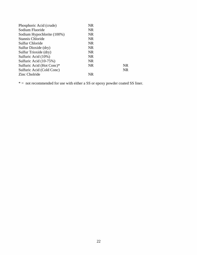
Phosphoric Acid (crude) NR Sodium Fluoride NR Sodium Hypochlorite (100%) NR Stannis Chloride NR Sulfur Chloride NR Sulfur Dioxide (dry) NR Sulfur Trioxide (dry) NR Sulfuric Acid (10%) NR Sulfuric Acid (10-75%) NR Sulfuric Acid (Hot Conc)* NR NR Sulfuric Acid (Cold Conc) NR Zinc Cholride NR * = not recommended for use with either a SS or epoxy powder coated SS liner.
22

Replacement parts list Part No. Description Part No. Description 293050D Vertical sash assembly-6 Foot 31877 Remote control service fixture-steam 29592 Vertical sash assembly-5 Foot 31878 Remote control service fixture-generic 29205 Vertical sash assembly-4 Foot 31879 Cold water gooseneck 2930308 Combination sash assbly-6 32165 DI/DW gooseneck foot 295870A Combination sash assbly-5 Foot 32163 CW gooseneck w/vacuum breaker 295866 Glass panel assbly for combination 32018 Aspirator sash only 11790 ¾ stainless steel plug button 31868 48” x 30” x 1” epoxy worksurface 295818B Light box- 4 and 5 foot 34778 60” x 30” x 1” epoxy worksurface 2930315 Light box-6 foot 31869 72” x 30” x 1” epoxy worksurface 292078 Worksurface airfoil- 4 foot 31870 3” x 6” cupsink 295583 Worksurface airfoil- 5 foot 31871 3” x 9” cupsink 293078 Worksurface airfoil- 6 foot 31872 3” x 11” cupsink 295908A Light box assbly- 4 & 5 foot 295860A Airwatch II Fume Hood alarm and control panel 295839 Light glass assbly- 4 & 5 foot 31873 Remote control service fixture air 2930314 Light box assbly- 6 foot 31874 Remote control service fixture vacuum 2930313 Light glass assbly- 6 foot 31875 Remote control service fixture gas 2920322 Top front bypass-4 foot 31876 Remote control service fixture 2920321 Top rear bypass- 4 foot DI/DW 295812D Top front bypass- 5 foot 295811D Top rear bypass- 5 foot 2930312 Top front bypass- 6 foot 2930311 Top rear bypass- 6 foot
23
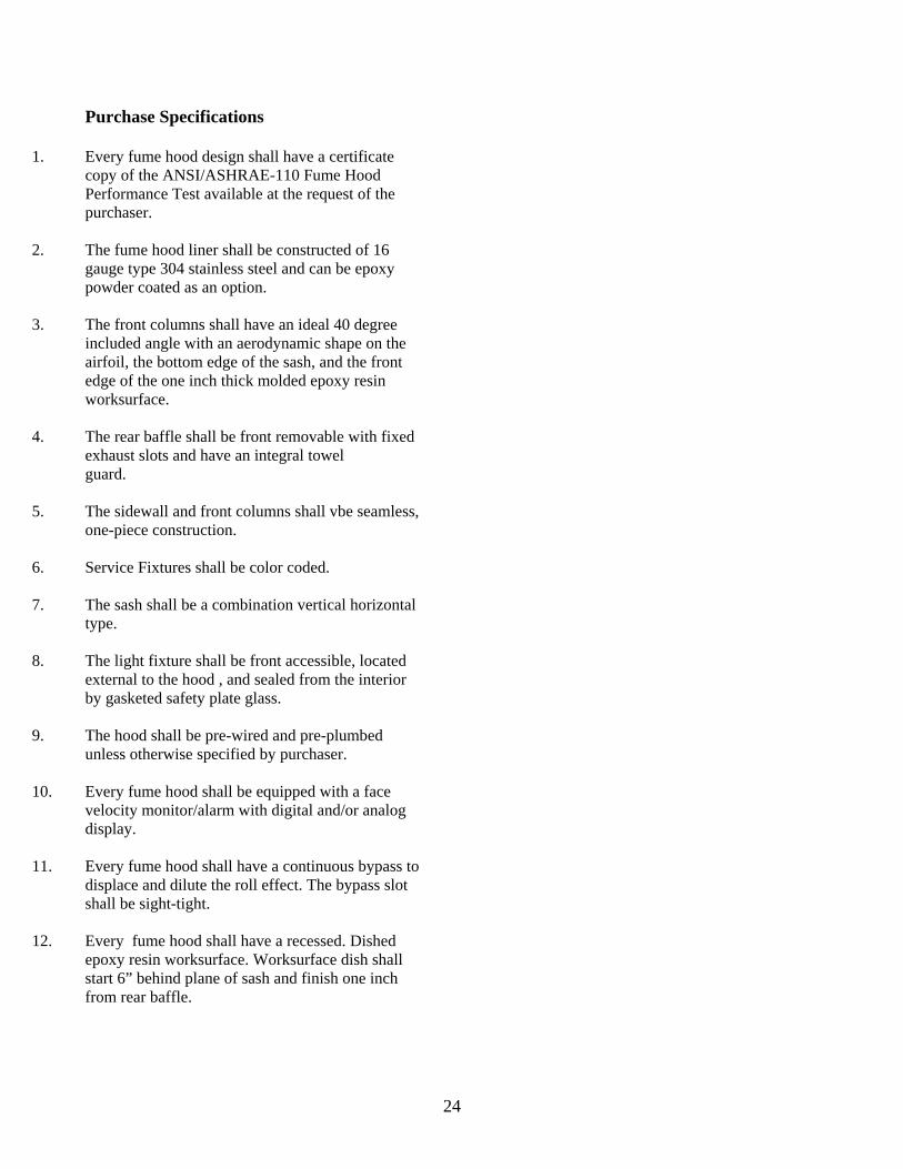
Purchase Specifications
1. Every fume hood design shall have a certificate copy of the ANSI/ASHRAE-110 Fume Hood Performance Test available at the request of the purchaser.
2. The fume hood liner shall be constructed of 16 gauge type 304 stainless steel and can be epoxy powder coated as an option.
3. The front columns shall have an ideal 40 degree
included angle with an aerodynamic shape on the airfoil, the bottom edge of the sash, and the front edge of the one inch thick molded epoxy resin worksurface.
4. The rear baffle shall be front removable with fixed exhaust slots and have an integral towel guard.
5. The sidewall and front columns shall vbe seamless, one-piece construction.
6. Service Fixtures shall be color coded.
7. The sash shall be a combination vertical horizontal
type.
8. The light fixture shall be front accessible, located external to the hood , and sealed from the interior by gasketed safety plate glass.
9. The hood shall be pre-wired and pre-plumbed unless otherwise specified by purchaser.
10. Every fume hood shall be equipped with a face velocity monitor/alarm with digital and/or analog display.
11. Every fume hood shall have a continuous bypass to displace and dilute the roll effect. The bypass slot shall be sight-tight.
12. Every fume hood shall have a recessed. Dished epoxy resin worksurface. Worksurface dish shall start 6” behind plane of sash and finish one inch from rear baffle.
24

Warranty The Baker Company, Inc. expressly represents and warrants all goods (a) to be specified ( and described) in The Baker Company catalogues and literature, and (b) to be free under normal use, service and testing (all as described in The Baker Company catalogues and literature) from defects in material and workmanship foe a period of twelve months from the invoice date. The exclusive remedy for any breach or violation of this warranty is as follows: The Baker Company, Inc. will F.O.B. Sanford, Maine furnish without charge repairs to or replacement parts or equipment which proved defective in material or workmanship. No claim may be made for any incidental or consequential damages.
NOTE: THIS WARRANTY IS IN LIEU OF ALL OTHER WARRANTIES, EXPRESSED OR IMPLIED, INCLUDING ANY IMPLIED WARRANTY OF MERCHANTABILITY OR FITNESS FOR A PARTICULAR PURPOSE UNLESS OTHERWISE AGREED IN WRITING SIGNED BY THE BAKER COMPANY. (THE BAKER COMPANY SHALL NOT BE RESPONSIBLE FOR ANY IMPROPER USE, INSTALLATION, SERVICE OR TESTING OF GOODS). NOTE: The ChemGARD unit is a bypass type fume hood for general laboratory use to enhance the end-user’s safety, but it is not a substitute for inadequate exhaust or unsafe laboratory practices. It is not designed to function as a perchloric acid or radioisotope hood. The safety officer and facilities manager should approve its use, define the required face velocity, and verify and maintain the proper exhaust for the end-user’s application. If there are any questions please call The Baker Company at (207) 324 – 8773.
25