Embed Size (px)
Citation preview
Operators Manual CoaLAB 6000
For in-vitro diagnostic use only!
Order Bedienungsanleitung CoaLAB 6000 Best. Nr.: 30.000.1615 German Version Operators Manual CoaLAB 6000 Order No.: 30.000.1616 English Version Revision History
Version Manual Date (mm/dd/yy)
Analyser Software-Version - Release -
1.0 10/29/99 1.0 Final release Version 1.2 02/20/01 1.02a Software update 1.3 07/17/01 1.02d Software update/corrections 1.4 05/07/02 1.03 Software update/corrections 1.5 08/12/02 1.03 Corrections 1.6 02/06/03 1.04 Software update/corrections 1.7 08/21/03 1.04 IVD update 1.8 11/26/04 1.04 Updates/Corrections
Copyright of Software All software by LABiTec LAbor BioMedical Technologies GmbH (in the following LABiTec-Software) is the intellectual property of the LABiTec LAbor BioMedical Technologies GmbH. Intellectual property rights shall remain with LABiTec LAbor BioMedical Technologies GmbH. You are entitled to use LABiTec-Software and the printed accompanying material at a place of work that cannot be transferred. Any violation of property rights or copyright or trademark or using conditions may be subject to legal action. LABiTec reserves the rights to modify the software, documentation as well as this operator manual without prior written notice. Your Distributor: (Please do not hesitate to contact your local distributor if you have any questions or problems.)
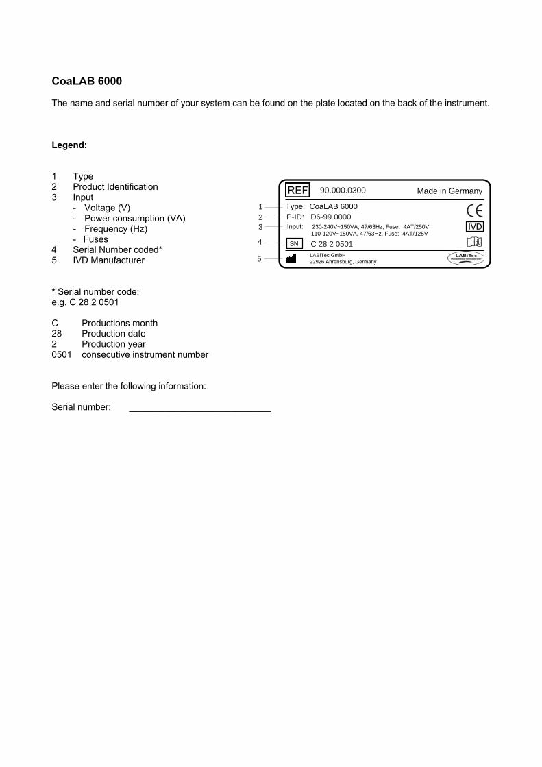
CoaLAB 6000 The name and serial number of your system can be found on the plate located on the back of the instrument. Legend: 1 Type 2 Product Identification 3 Input
- Voltage (V) - Power consumption (VA) - Frequency (Hz) - Fuses
4 Serial Number coded* 5 IVD Manufacturer * Serial number code: e.g. C 28 2 0501 C Productions month 28 Production date 2 Production year 0501 consecutive instrument number Please enter the following information: Serial number: ____________________________
Made in Germany
Type: CoaLAB 6000
Input: 230-240V~150VA, 47/63Hz, Fuse: 4AT/250V 110-120V~150VA, 47/63Hz, Fuse: 4AT/125V
LABiTec GmbH 22926 Ahrensburg, Germany
IVD
SN C 28 2 0501
P-ID: D6-99.0000123
4
5
90.000.0300
Contents
CoaLAB 6000 – Operators Manual 1.8 Page 1
Table of contents
1 INTRODUCTION................................................................. 3 1.1 Definitions..............................................................................4 1.2 Description of the system ....................................................5 1.3 Measuring principle ..............................................................9 1.4 Software Overview................................................................9
2 HAZARD AND PRECAUTION.......................................... 11
3 WARRANTY ..................................................................... 15
4 SERVICE .......................................................................... 16
5 INSTALLATION................................................................ 17 5.1 Unpacking and installation of the system ........................17
5.1.1 How to prepare the installation area .........................................17 5.1.2 Check Contents.........................................................................17 5.1.3 Unpacking the system...............................................................18 5.1.4 Assembly of the system ............................................................19
5.1.4.1 Mount the diluter syringe and tubes.......................................19 5.1.4.2 Connect the Liquid System Containers .................................21 5.1.4.3 Connect the Barcode Scanner (Optional)..............................22 5.1.4.4 Connect a HOST or Personal Computer to the System ........22 5.1.4.5 Insert and change printer paper.............................................23 5.1.4.6 Mount the cuvette waste box .................................................24
5.2 Instrument control Card (ICC)............................................25 5.3 Language Setup ..................................................................25
6 OPERATION..................................................................... 26 6.1 Routine Operation <1 ROUTINE MENU>...........................26
6.1.1 Switch ON the system...............................................................27 6.1.2 Rinsing with distilled water ........................................................27 6.1.3 Disinfection of waste tubing (Terralin), change of FW-Filter.....28 6.1.4 Rinsing with Washing Solution..................................................31 6.1.5 Loading and unloading reagents...............................................32 6.1.6 Delete joblist, delete samples ...................................................34 6.1.7 Enter a new joblist .....................................................................35 6.1.8 Handle the joblist.......................................................................37 6.1.9 Print of a joblist..........................................................................37 6.1.10 Start measuring, load cuvette bars ...........................................38 6.1.11 Interrupt a current run (User interrupt) ......................................41 6.1.12 Print results, send results to HOST...........................................42 6.1.13 Refill liquids, clean containers...................................................43 6.1.14 Empty and clean the waste water container .............................44
6.2 Enter Test Parameter ..........................................................45 6.2.1 Enter Reagent Specific Parameters..........................................45
6.2.1.1 Enter a reference curve (PT, for example) ............................45
Contents
CoaLAB 6000 – Operators Manual 1.8 Page 2
6.2.1.2 Enter ISI value .......................................................................47 6.2.1.3 Enter RATIO (APTT for example)..........................................49 6.2.1.4 Enter normal ranges (for example PT) ..................................50
6.2.2 Enter Method Parameter...........................................................52 6.2.2.1 Enter single or double determinations ...................................52 6.2.2.2 Enter PT Test Parameter .......................................................54 6.2.2.3 Enter APTT Test Parameter ..................................................58 6.2.2.4 Enter Fibrinogen Test Parameter ..........................................63 6.2.2.5 Print of Test Parameters (Fibrinogen for example) ...............67
6.2.3 Read ChipCARD to load a new test (Read test).......................69 6.2.4 Save Tests on a ChipCARD......................................................71 6.2.5 Print of Test Parameters (Print test)..........................................73 6.2.6 Delete Test ................................................................................74
6.3 STAT Management..............................................................75 6.4 General Setting (SETUP MENU).........................................81
6.4.1 Define Primary Tubes ...............................................................82 6.4.2 Define STAT positions in the sample rotor ...............................83 6.4.3 Date and Time...........................................................................84 6.4.4 Printer Setup .............................................................................85 6.4.5 Beeper Setup ............................................................................86 6.4.6 Set PIN Code ............................................................................87 6.4.7 Language ..................................................................................88 6.4.8 Print of Setup Parameters.........................................................89
6.5 Removing cuvette bars from the system..........................90 6.6 Switch OFF the system.......................................................90
7 FAILURES ........................................................................ 92 7.1 Status Messages.................................................................93 7.2 Application Errors...............................................................94 7.3 Non-Fatal Errors..................................................................95 7.4 Fatal Errors..........................................................................96 7.5 Change fuses.......................................................................97
8 ANNEX.............................................................................. 99 8.1 Maintenance and Hygiene ..................................................99
8.1.1 Cleaning and Disinfection of housing and waste box .............100 8.1.2 How to dispose of used disposables.......................................100 8.1.3 How to dispose the used system ............................................100
8.2 Protocol of Maintenance Check.......................................101 8.3 Safety Specifications........................................................101 8.4 Technical Data...................................................................101 8.5 Accessories and Consumables .......................................104 8.6 Mathematics ......................................................................106 8.7 Adaptation of coagulation reagents................................106 8.8 Packing of the system, preparation of transport ...........107
Introduction
CoaLAB 6000 – Operators Manual 1.8 Page 3
1 Introduction The instrument type CoaLAB 6000 (in the following titled as analyzer/system) is a compact and automatic blood coagulation analyzer for routine and STAT samples in the clinical laboratory. For in-vitro diagnostic use only! The system can perform 3 clotting tests such as PT / aPTT and Fibrinogen simultaneously. It can perform additional tests such as Thrombin Time, when the ChipCARD is used to replace any of the 3 standard tests. The system can work in batch mode (individual test handling) or in random-access mode simultaneous test handling). In both cases the analyzer will manage the results automatically. The analyzer has 6 digital measuring channels based on the turbodensitometric FIBRINTIMERTM measuring principle. To avoid sedimentation a Teflon stirrer (2 stirrers are included) can be added to the reagent. The reagent positions are always at room temperature.
Purpose of this instruction manual The instruction manual describes the system and is directed to all users of the system. This instruction manual gives all information necessary for the installation, operation, maintenance, storing, packing, and transport of the system. Service information is handled separately. Careful observation of all information, especially of hazards and precautions will ensure the correct and safe operation of the analyzer. Therefore it is absolutely necessary to read the instruction manual completely. This instruction manual was prepared with greatest care. Should you have any questions please refer to your distributor or to the manufacturer.
Validity of this instruction manual All information in this instruction manual refers to this system: For all requests please indicate type and serial number of your system which can be found on the type plate on the back of the instrument or under ‘identification’ of this manual.
Introduction
CoaLAB 6000 – Operators Manual 1.8 Page 4
1.1 Definitions In this manual the following terms are used:
Analyzer/System/ Instrument This is the CoaLAB 6000.
Manufacturer The manufacturer according to IVD directive 98/79/EC is the company/dealer who distributes the system within the respective country.
User User is the current operator of the instrument.
Personnel Personnel are all people authorised to work with the system and meeting the specifications required by the manufacturer for the operation of the system.
Skilled personnel All people who are especially qualified and authorised to handle specific matters in connection with the instrument.
Life phases All phases of the system from end of manufacture to disposal of the instrument. In this instruction manual all phases of the system will be mentioned.
QUALIFICATION OF PERSONNEL The different life phases of the system require different qualifications of the personnel. The minimum requirements for qualification are described at the beginning of each chapter or at the proper place in this manual.
Introduction
CoaLAB 6000 – Operators Manual 1.8 Page 5
1.2 Description of the system
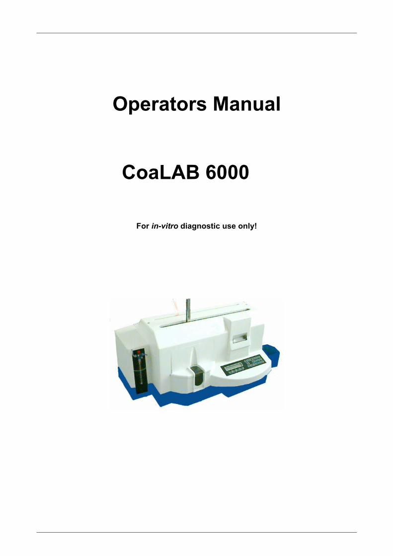
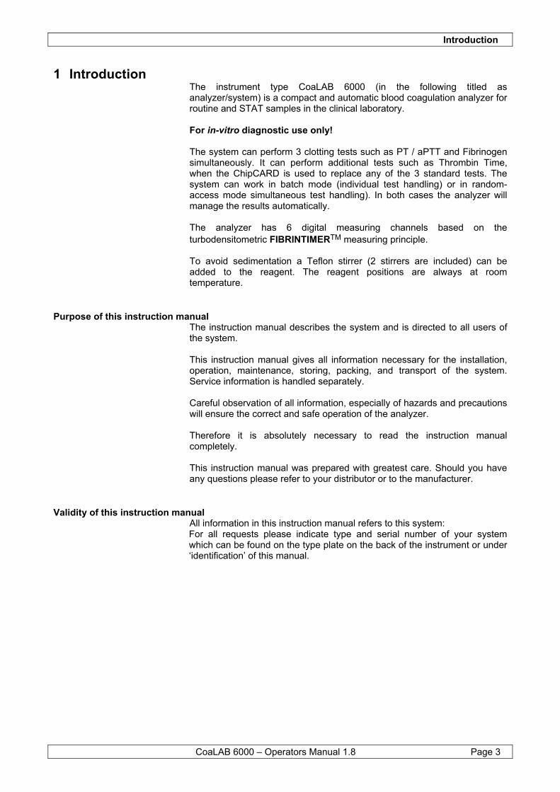
The System No additional equipment is necessary to operate the instrument. The integrated module and system software controls the system and manages all data. The system can be connected to a host computer for the management of results. All measured results, reagent and test-specific data can be printed on the internal thermal printer. The system will be loaded with samples, reagents, and cuvette bars. The samples in primary tubes (Becton Dickinson Vacutainer, Sarstedt Monovette or specially designed sample cups) are loaded into the sample rotor. At any time STAT samples can be loaded for priority handling. The system can either work sample-orientated or test-selective.
Figure 1 System Connections
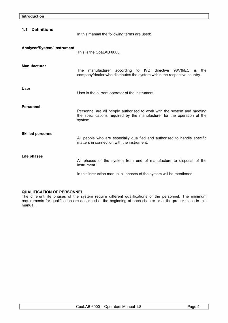
Figure 2 Modules
ENTER
ESCF4
F3
F2
F1
78
904
56
32
1
Connection of containers for system liquidsSensor connectionDist. water (green)
Sensor connectionWaste water (red)
Pipettor with steel tubing and level sensor with tubing connected to dilutor
Barcode scanner
RS 232 interface
Power supply ON/OFF
Main plug
Cuvette waste boxSmall loading lid
Big loading lid
Key pad
Printer
ChipCARD
Dilutor
130-3-12-13130-3-12-13
TSGTSG
a3a2
11
11
gr-nrot blauschwarz rot
schwarzgr-n blau
weissweissblaublaunc.nc.gr-ngr-n
schwarzschwarz
rotrotrotrotschwarz
schwarzgr-ngr-nnc.nc.blaublauweissweiss
ENTER
ESC
F4F3
F2F1
78
9
0
45
63
21
50%
12
34
5
6a 6b 6c7 8 9 10
Introduction
CoaLAB 6000 – Operators Manual 1.8 Page 6
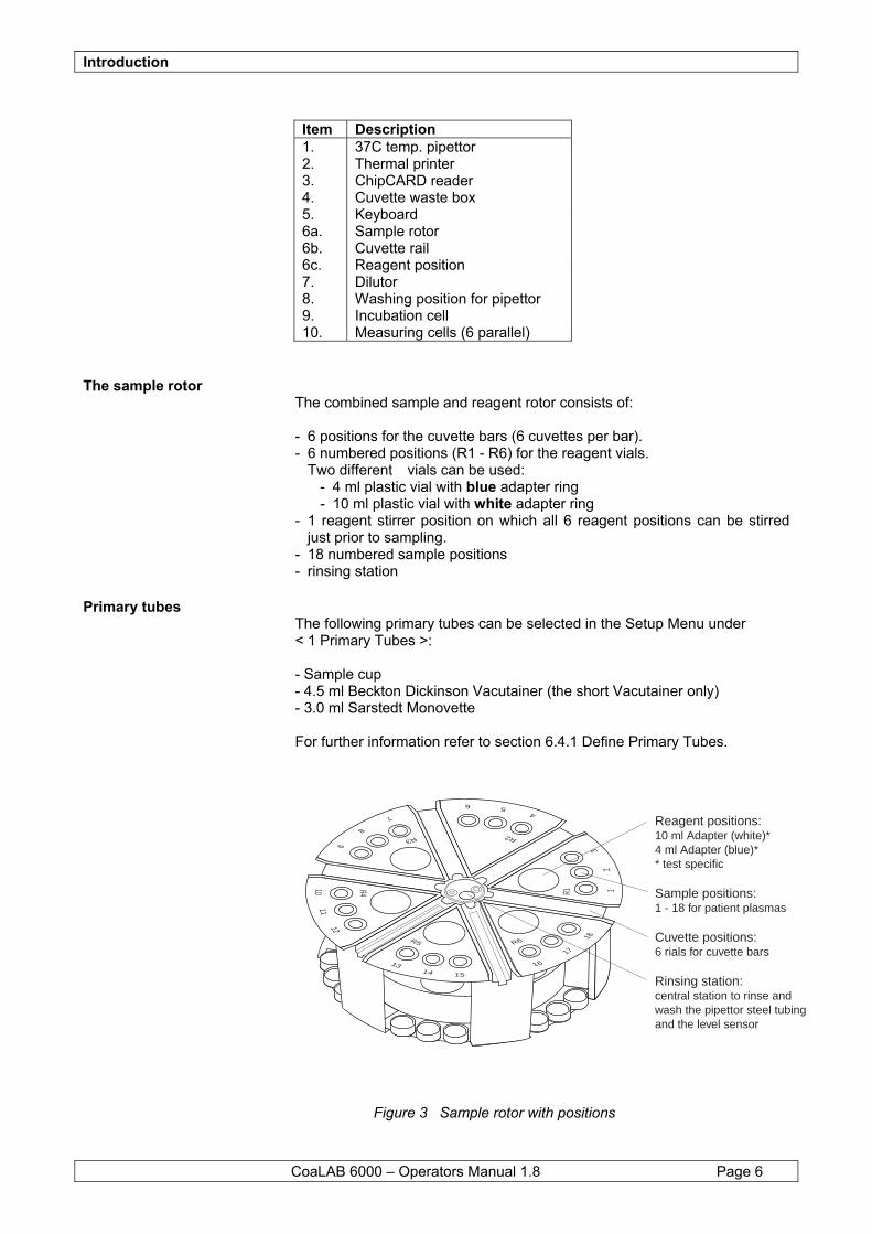
Item Description 1. 37C temp. pipettor 2. Thermal printer 3. ChipCARD reader 4. Cuvette waste box 5. Keyboard 6a. Sample rotor 6b. Cuvette rail 6c. Reagent position 7. Dilutor 8. Washing position for pipettor 9. Incubation cell 10. Measuring cells (6 parallel)
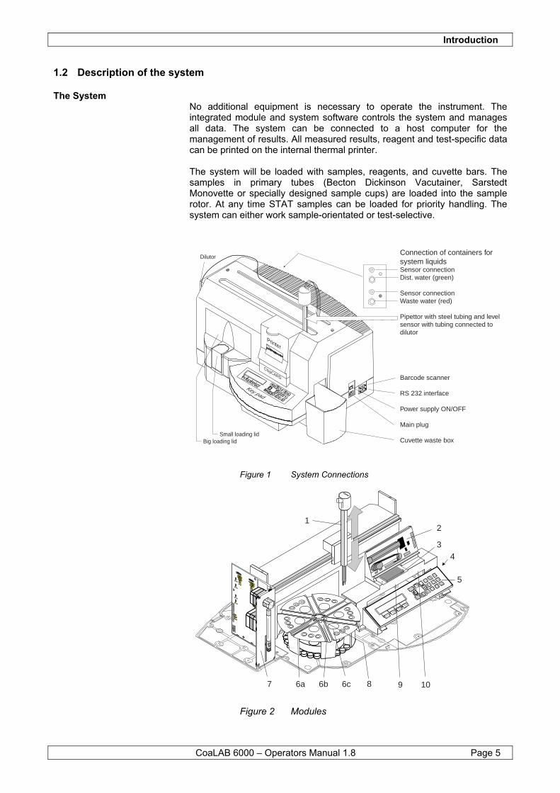
The sample rotor The combined sample and reagent rotor consists of: - 6 positions for the cuvette bars (6 cuvettes per bar). - 6 numbered positions (R1 - R6) for the reagent vials. Two different vials can be used: - 4 ml plastic vial with blue adapter ring - 10 ml plastic vial with white adapter ring - 1 reagent stirrer position on which all 6 reagent positions can be stirred
just prior to sampling. - 18 numbered sample positions - rinsing station
Primary tubes The following primary tubes can be selected in the Setup Menu under < 1 Primary Tubes >: - Sample cup - 4.5 ml Beckton Dickinson Vacutainer (the short Vacutainer only) - 3.0 ml Sarstedt Monovette For further information refer to section 6.4.1 Define Primary Tubes.
Figure 3 Sample rotor with positions
R5
1314 15
16
17
18
12
3
45
6
7
8
9
1011
12
R6
R1
R2R3
R4
Reagent positions:10 ml Adapter (white)*4 ml Adapter (blue)** test specific
Sample positions:1 - 18 for patient plasmas
Cuvette positions:6 rials for cuvette bars
Rinsing station:central station to rinse andwash the pipettor steel tubingand the level sensor
Introduction
CoaLAB 6000 – Operators Manual 1.8 Page 7
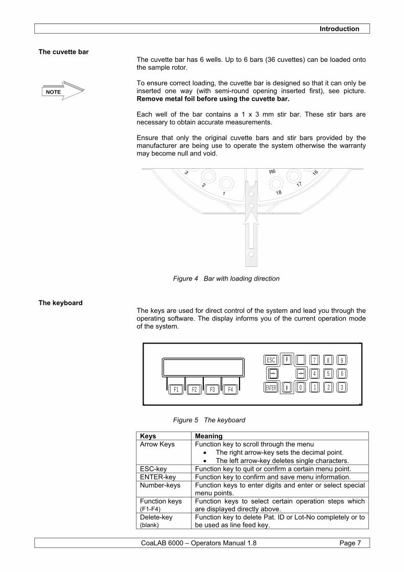
The cuvette bar The cuvette bar has 6 wells. Up to 6 bars (36 cuvettes) can be loaded onto the sample rotor. To ensure correct loading, the cuvette bar is designed so that it can only be inserted one way (with semi-round opening inserted first), see picture. Remove metal foil before using the cuvette bar. Each well of the bar contains a 1 x 3 mm stir bar. These stir bars are necessary to obtain accurate measurements. Ensure that only the original cuvette bars and stir bars provided by the manufacturer are being use to operate the system otherwise the warranty may become null and void.
Figure 4 Bar with loading direction
The keyboard The keys are used for direct control of the system and lead you through the operating software. The display informs you of the current operation mode of the system.
Figure 5 The keyboard Keys Meaning Arrow Keys Function key to scroll through the menu
• The right arrow-key sets the decimal point. • The left arrow-key deletes single characters.
ESC-key Function key to quit or confirm a certain menu point. ENTER-key Function key to confirm and save menu information. Number-keys Function keys to enter digits and enter or select special
menu points. Function keys (F1-F4)
Function keys to select certain operation steps which are displayed directly above.
Delete-key (blank)
Function key to delete Pat. ID or Lot-No completely or to be used as line feed key.
NOTE
ENTER
ESC
F4F3F2F1
7 8 9
0
4 5 6
321
Introduction
CoaLAB 6000 – Operators Manual 1.8 Page 8
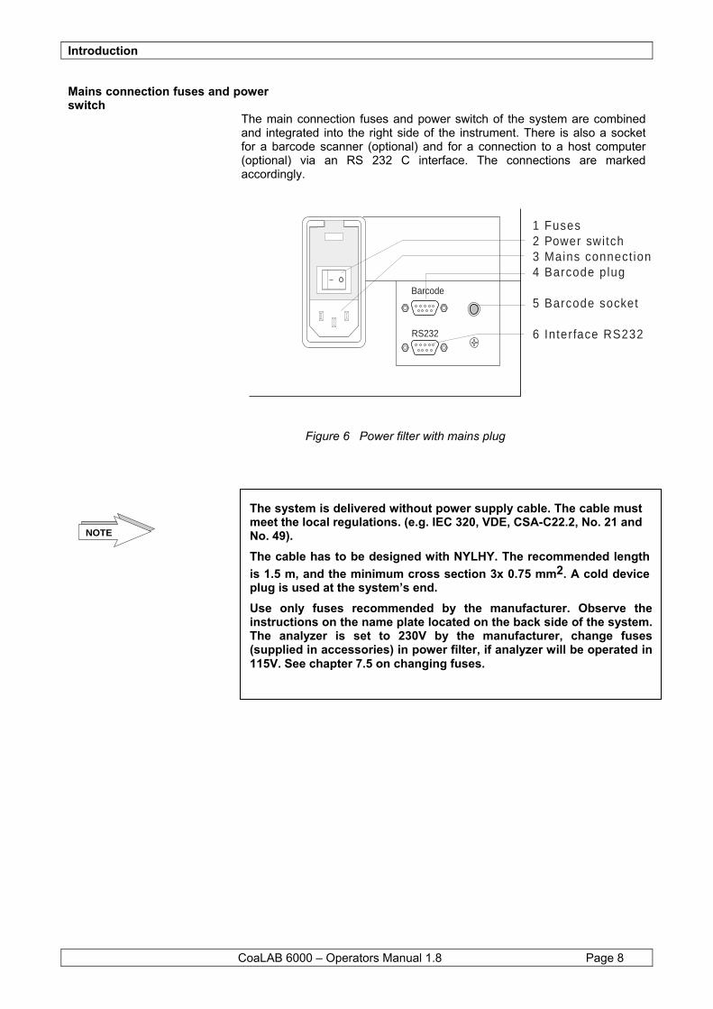
Mains connection fuses and power switch
The main connection fuses and power switch of the system are combined and integrated into the right side of the instrument. There is also a socket for a barcode scanner (optional) and for a connection to a host computer (optional) via an RS 232 C interface. The connections are marked accordingly.
Figure 6 Power filter with mains plug
RS232
Barcode
1 Fuses2 Power switch3 Mains connect ion4 Barcode plug
5 Barcode socket
6 Interface RS232
The system is delivered without power supply cable. The cable must meet the local regulations. (e.g. IEC 320, VDE, CSA-C22.2, No. 21 and No. 49). The cable has to be designed with NYLHY. The recommended length is 1.5 m, and the minimum cross section 3x 0.75 mm2. A cold device plug is used at the system’s end. Use only fuses recommended by the manufacturer. Observe the instructions on the name plate located on the back side of the system. The analyzer is set to 230V by the manufacturer, change fuses (supplied in accessories) in power filter, if analyzer will be operated in 115V. See chapter 7.5 on changing fuses.
NOTE
Introduction
CoaLAB 6000 – Operators Manual 1.8 Page 9
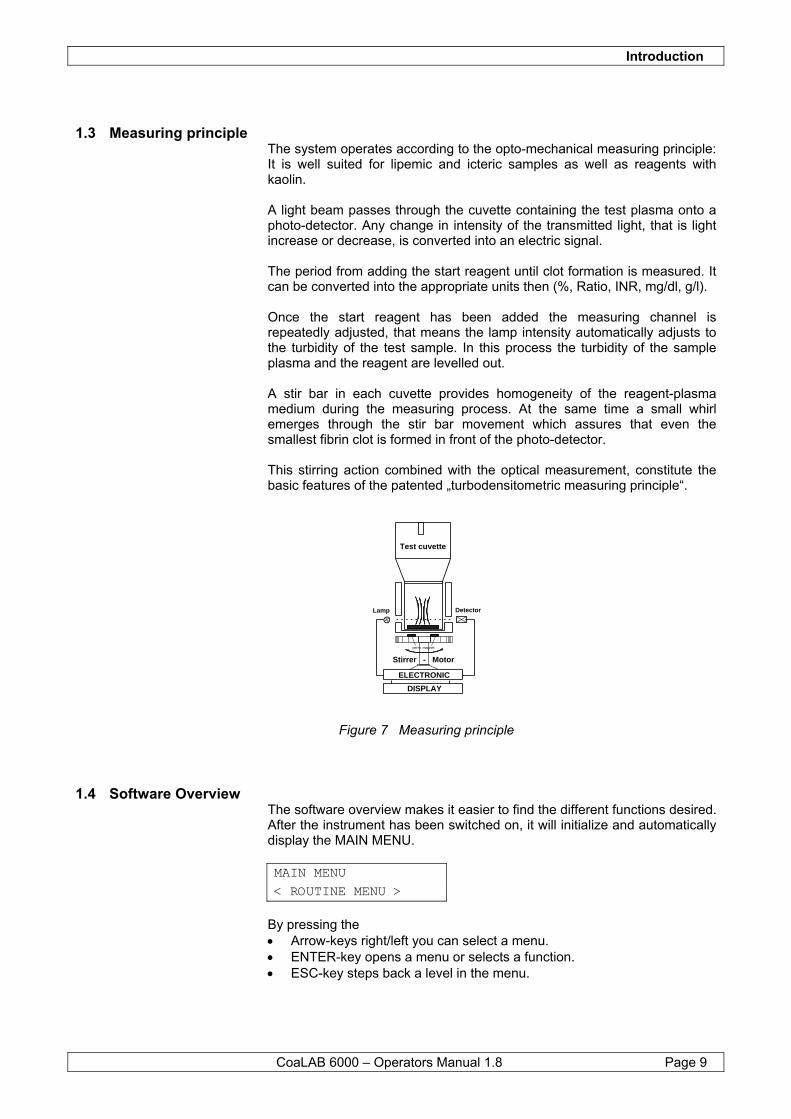
1.3 Measuring principle The system operates according to the opto-mechanical measuring principle: It is well suited for lipemic and icteric samples as well as reagents with kaolin. A light beam passes through the cuvette containing the test plasma onto a photo-detector. Any change in intensity of the transmitted light, that is light increase or decrease, is converted into an electric signal. The period from adding the start reagent until clot formation is measured. It can be converted into the appropriate units then (%, Ratio, INR, mg/dl, g/l). Once the start reagent has been added the measuring channel is repeatedly adjusted, that means the lamp intensity automatically adjusts to the turbidity of the test sample. In this process the turbidity of the sample plasma and the reagent are levelled out. A stir bar in each cuvette provides homogeneity of the reagent-plasma medium during the measuring process. At the same time a small whirl emerges through the stir bar movement which assures that even the smallest fibrin clot is formed in front of the photo-detector. This stirring action combined with the optical measurement, constitute the basic features of the patented „turbodensitometric measuring principle“.
Figure 7 Measuring principle
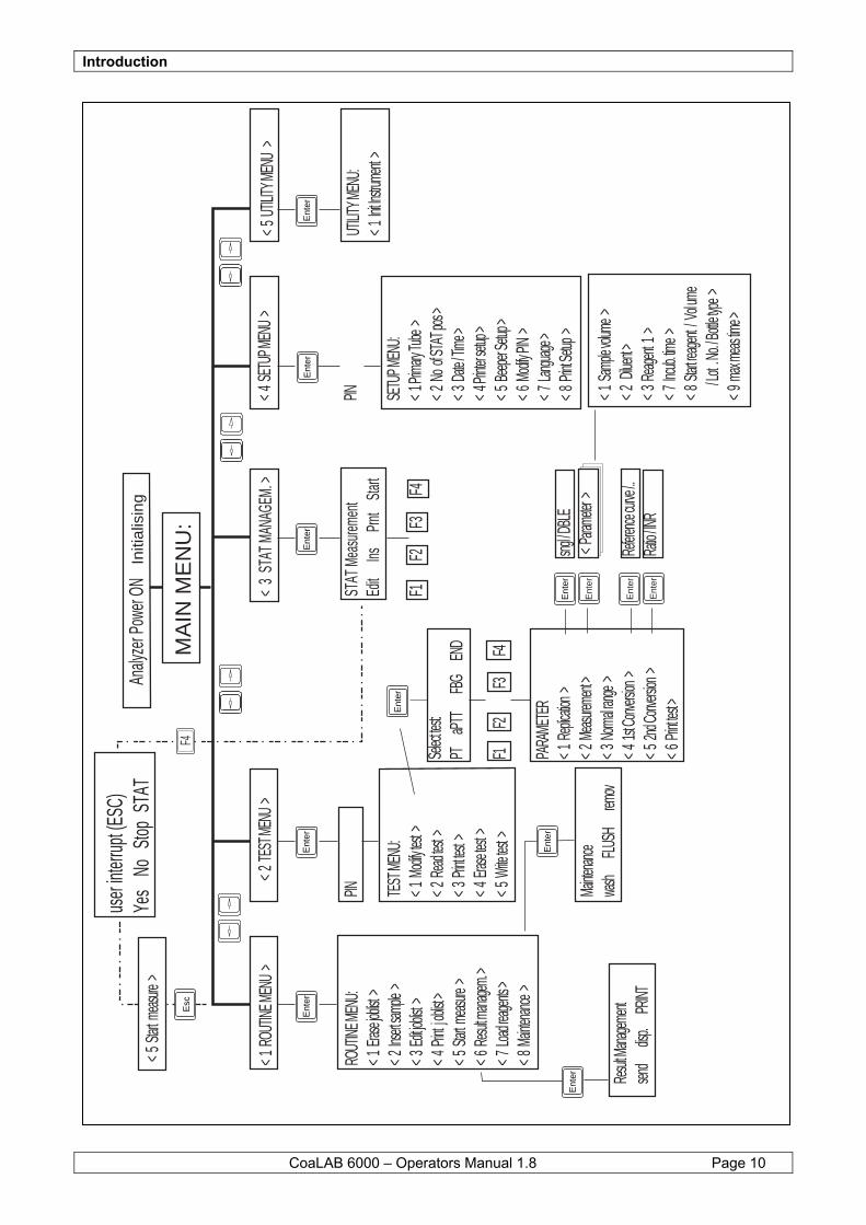
1.4 Software Overview The software overview makes it easier to find the different functions desired. After the instrument has been switched on, it will initialize and automatically display the MAIN MENU.
MAIN MENU < ROUTINE MENU >
By pressing the • Arrow-keys right/left you can select a menu. • ENTER-key opens a menu or selects a function. • ESC-key steps back a level in the menu.
Test cuvette
Lamp Detector
ELECTRONIC
DISPLAY
Stirrer - Motor
perm. magnet
Introduction
CoaLAB 6000 – Operators Manual 1.8 Page 10
< 1 R
OUTIN
E MEN
U >
ROUT
INE ME
NU:
< 1 E
rase jo
blist >
< 2 In
sert sa
mple
>< 3
Edit
joblist
>< 4
j oblis
t >< 5
Start
meas
ure >
< 6 R
esult m
anagem
. >< 7
Load
reagen
ts >< 8
Main
tenanc
e >
< 2 TE
ST ME
NU >
PIN
TEST
MENU
:< 1
Modi
fy test
>< 2
Read
test >
< 3 P
rint tes
t >< 4
Eras
e test
>< 5
Write
test >
< 3
STAT
MAN
AGEM
. >
STAT
Mea
surem
ent
Edit
InsPr
ntSta
rt
F1F2
F3F4
< 4 S
ETUP
MENU
>
PIN
SETU
P MEN
U:< 1
Prima
ry Tube
>< 2
No o
f STA
T pos
>< 3
Date
/ Time
>< 4
Printe
r setup
>< 5
Beep
er Setu
p >< 6
Modi
fy PIN
>< 7
Langu
age >
< 8 P
rint Se
tup >
< 1 S
ample
volum
e >< 2
Dilue
nt >< 3
Reag
ent 1
>< 7
Incub
. time >
< 8 S
tart rea
gent /
Vol um
e
/ Lot
. No. /
Bottle
type >
< 9 m
ax me
as tim
e >
< 5 U
TILITY
MENU
>
UTILIT
Y MEN
U:< 1
Init In
strume
nt >
Analy
zer P
ower
ON
Initi
alis
ing
MA
IN M
EN
U:
user
interr
upt (E
SC)
Yes
No
Stop
STAT
< 5 S
tart m
easure
>
F4
Ent
er
Ent
er
Ent
er
Ent
erE
nter
Ent
er
Ent
er
Ent
er
Esc
Selec
t test:
PT aP
TT
FBG
END
F1F2
F3F4
PARA
METE
R< 1
Repl
ication
>sng
l / DBL
E< 2
Meas
ureme
nt > <
Param
eter >
< 3 N
ormal r
ange >
< 4 1s
t Conv
ersion
>Re
ference
curve
/..< 5
2nd C
onvers
ion >
Ratio
/ INR
< 6 P
rint tes
t >
Mainte
nance
wash
FL
USH
rem
ovE
nter
Ent
er
Ent
er
Ent
er Resul
t Mana
gement
send
dis
p.
Hazard and Precaution
CoaLAB 6000 – Operators Manual 1.8 Page 11
2 Hazard and Precaution This section contains the safety regulations that must be observed by all users of the system, to ensure safe and economic operation.
Importance of safety regulations All safety instructions in this instruction manual must be observed to avoid damage to persons, property and the environment. All local safety and environmental regulations and guidelines must also be observed.
Disregarding of safety regulations Disregarding these safety regulations or technical specifications may result in accidents with personnel or equipment, or environmental damages.
Hazards and Precautions The system has been delivered by the manufacturer in a technically flawless condition. In order to keep this condition the user must follow the following safety regulations of this manual. The system must be operated by skilled personnel only.
Warning signals Two different warning signals with different meanings are used in this section.
ATTENTION! Potential danger may cause minor injury or equipment damage, if no precautions are taken.
WARNING! Potential danger may cause severe injury or death if no precautions are taken.
NOTE Note introduces rules to be observed.
Hazard and Precaution
CoaLAB 6000 – Operators Manual 1.8 Page 12
Electrical safety:
WARNING! Ensure that the operating voltage is set correctly before the instrument is connected to the main power supply. Use only grounded sockets and extension cords when connecting the instrument to a power supply. Never disconnect grounding contacts. Never disconnect the grounding contacts intentionally. There is the risk of an electrical shock if - The protective conductor is interrupted within or outside the device - The grounded contact has been disconnected from the line. Never remove protective guards or secured components, since you could expose electrically live parts. Even after the instrument has been switched off, some parts may contain voltage due to electrical charge. All current carrying parts are sources of danger for an electrical shock. Never use the instrument on a moist surfaces (floor, worktable or countertop), or place containers of liquids on top of the instrument. Liquids spilled into the instrument may cause an electrical shock. Switch off the instrument and disconnect it from all power sources before performing maintenance or repair work. Perform only the maintenance/repair work described in this manual; unauthorized work on the instrument may cancel the warranty, and require expensive service work. All work which requires the instrument to be opened under voltage must only be carried out by a technician who is familiar with the risks related thereto. Use only replacement fuses of the stated type and with the stated minimum current; - Never use ‘repaired’ fuses. - Never short-circuit the fuse holder.
Fire and Explosion hazards:
WARNING! Do not place the instrument near explosive mixtures of flammable gases, such as oxygen or hydrogen; electrical sparks could cause fire or explosions.
Mechanical Safety (system in operation)
WARNING! Never remove housing parts while the instrument is on; moving parts such as the fan or motor drives may cause injury. Always close the sample rotor-loading inlet during operation, to avoid contact with moving parts. The probe will not stop when the loading inlet is open. Ensure that the pipettor does not stop over the sample rotor or the measuring block when the instrument is switched off.
Hazard and Precaution
CoaLAB 6000 – Operators Manual 1.8 Page 13
- Use the protection cap for the pipettor if the system will not be operated for a long time, to avoid damage and contamination.
- Do not open covers during a run, to avoid damaging the pipettor. If safe operation of the instrument is not possible switch the instrument off and secure it against use if: - The instrument is damaged - The instrument does not work properly - The instrument has been stored / transported under adverse conditions - The instrument has experienced severe temperature fluctuations
Samples, Reagents
WARNING! Follow the instructions on the directional inserts for the correct use of reagents. Avoid skin contact with samples and/or test reagents, as well as those instrument parts that touch samples and/or test reagents. All instrument parts are potentially infectious, and reagents might irritate mucous membranes and the skin. All liquid and waste containers which carry sample and/or test reagents are marked with a biohazard symbol. If sample material is spilled onto the instrument, wipe it off immediately and decontaminate the affected surfaces. Ensure that no foam or air bubbles are on the surface of reagents and sample material prior to loading the system: their presence could influence the measured results and the level detection of the needle. Ensure reagents are used at room temperature only. Before using sample cups and reagent vials make sure to remove all covers/lids beforehand. Do not use organic solvents unless explicitly authorized by the manufacturer, as their use may result in damage to the cuvette bars, primary tubes, and waste water tubes.
Waste Liquids:
WARNING! Dispose of waste liquids must be in compliance with applicable regulations.
Accuracy and Precision of Results:
WARNING! Measure control samples and ensure the instrument is operating properly to obtain accurate results. Inaccurate results may lead to a false diagnosis and endanger the patient.
Hazard and Precaution
CoaLAB 6000 – Operators Manual 1.8 Page 14
User Qualification:
WARNING! The system should be operated by trained personnel only.
Barcode Scanner:
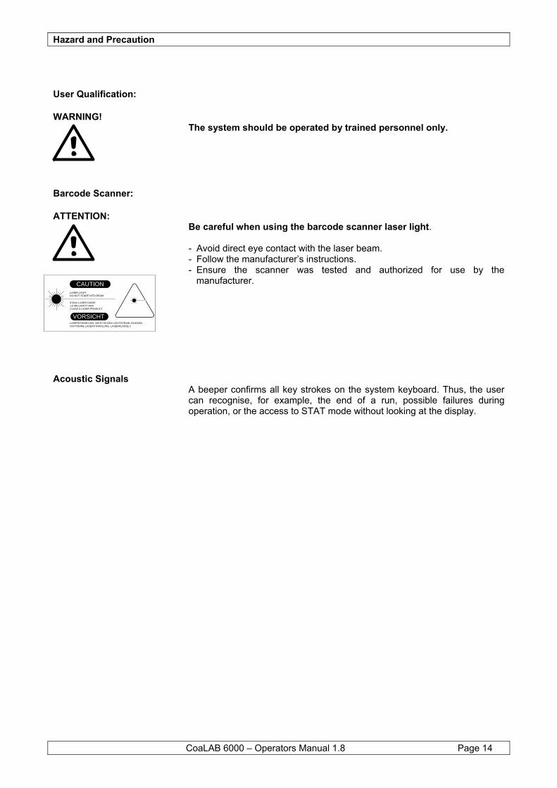
ATTENTION: Be careful when using the barcode scanner laser light. - Avoid direct eye contact with the laser beam. - Follow the manufacturer’s instructions. - Ensure the scanner was tested and authorized for use by the
manufacturer.
Acoustic Signals A beeper confirms all key strokes on the system keyboard. Thus, the user can recognise, for example, the end of a run, possible failures during operation, or the access to STAT mode without looking at the display.
LASER LIGHT DO NOT STARE INTO BEAM
CAUTION
670nm LASER DIODE1.0 MILLIWATT MAXCLASS II LASER PRODUCT
VORSICHTLASERSTRAHLUNG, NICHT IN DEN LICHTSTRAHL BLICKEN,SICHTBARE LASERSTRAHLUNG, LASERKLASSE 2
Warranty
CoaLAB 6000 – Operators Manual 1.8 Page 15
3 Warranty The representatives or authorised dealers warrant that the system does not have any material or manufacturing damages after installation if the instruction manual has been observed. The warranty does not apply for damages which are caused - By accidents, negligence, or non-observation of the instruction manual, - By using inadmissible reagents or disposables, or - By operating the instrument in an environment contradicting the
specifications of this instruction manual. Repair and service work must be carried out by technicians who have been authorised.
Service
CoaLAB 6000 – Operators Manual 1.8 Page 16
4 Service The representatives or authorised dealers guarantee to carry out repair work during the official working hours from Monday to Friday with the exception of public holidays. If you need service outside of that time contact our parent company or our authorised dealer.
Installation
CoaLAB 6000 – Operators Manual 1.8 Page 17
5 Installation This section describes how to unpack, install and prepare the instrument for use.
Safety regulations We assume that you have read chapter 2 Hazard and Precaution carefully.
5.1 Unpacking and installation of the system
5.1.1 How to prepare the installation area
Select a stable and level area for installation. Ensure the power cable will reach the outlet without using any extension cords. Ensure there is enough light for proper operation, but no direct sunlight.
Ensure there will be a cleared space of at least 12 inches (30 cm) to the sides and rear of the system, to allow easy access and air circuation. Ensure the space above the system will be clear of equipment, supplies and shelves.
5.1.2 Check Contents The instrument weighs about 35 pounds (17 kg), and can be carried or moved by one person. For the safety of the instrument and yourself, however, you should move the instrument using a rolling cart of have someone assist you.
• Place box on the floor • Remove all small parts from the box first, and ensure all accessories and disposables listed in section 8.5 have been received.
NOTE
NOTE
Do not put the analyzer on a shelf or on a roll-desk. Protect from direct sun light, significant temperature changes, humidity, and voltage variations.
Do not damage any packaging material, and keep them for possible later use, including the transport protection devices. Store them away from heat and humidity.
Installation
CoaLAB 6000 – Operators Manual 1.8 Page 18
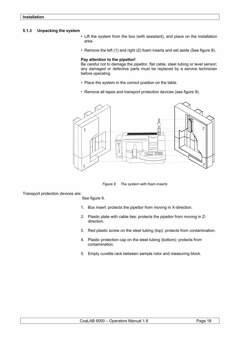
5.1.3 Unpacking the system • Lift the system from the box (with assistant), and place on the installation
area. • Remove the left (1) and right (2) foam inserts and set aside (See figure 8). Pay attention to the pipettor! Be careful not to damage the pipettor, flat cable, steel tubing or level sensor; any damaged or defective parts must be replaced by a service technician before operating. • Place the system in the correct position on the table. • Remove all tapes and transport protection devices (see figure 9).
Figure 8 The system with foam inserts
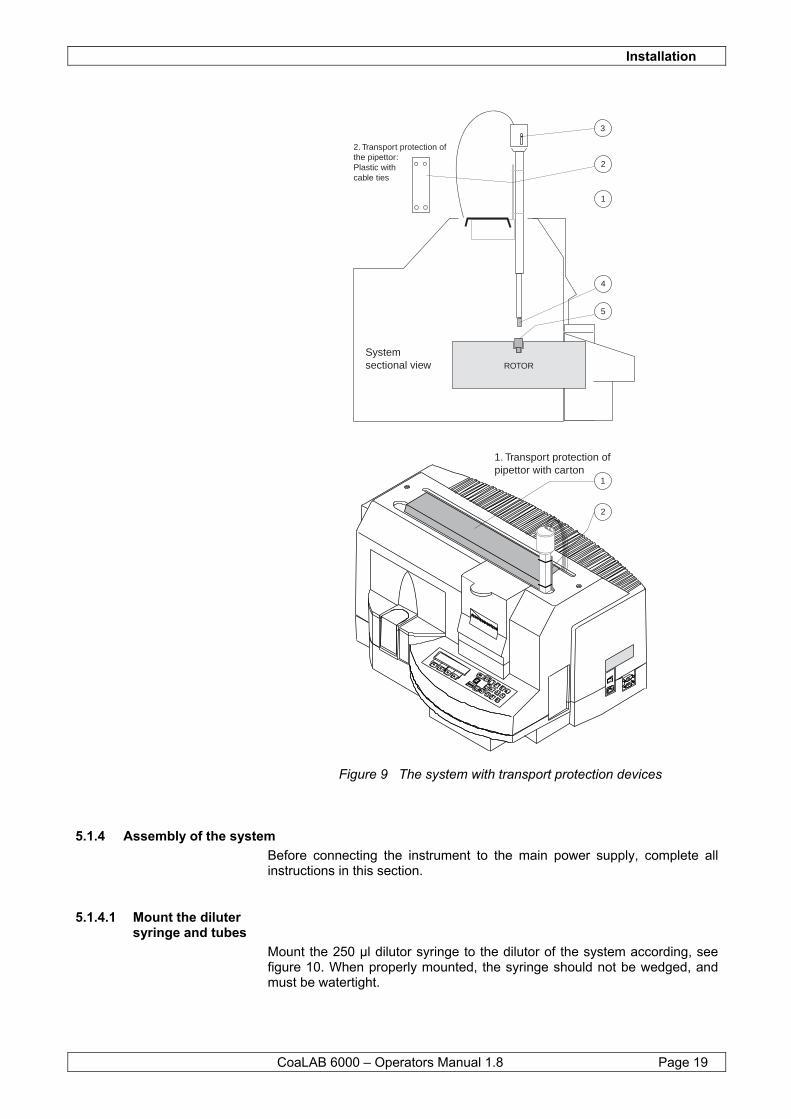
Transport protection devices are: See figure 9.
1. Box insert: protects the pipettor from moving in X-direction. 2. Plastic plate with cable ties: protects the pipettor from moving in Z-
direction. 3. Red plastic screw on the steel tubing (top): protects from contamination. 4. Plastic protection cap on the steel tubing (bottom): protects from
contamination. 5. Empty cuvette rack between sample rotor and measuring block.
1
1
2
2
Installation
CoaLAB 6000 – Operators Manual 1.8 Page 19
Figure 9 The system with transport protection devices
5.1.4 Assembly of the system Before connecting the instrument to the main power supply, complete all instructions in this section.
5.1.4.1 Mount the diluter syringe and tubes
Mount the 250 µl dilutor syringe to the dilutor of the system according, see figure 10. When properly mounted, the syringe should not be wedged, and must be watertight.
2. Transport protection ofthe pipettor:Plastic withcable ties
2
2
3
1
1
4
5
ROTOR
ENTER
ESCF4
F3
F2
F1
7
8
904
5
6
3
2
1
1. Transport protection of pipettor with carton
Systemsectional view
Installation
CoaLAB 6000 – Operators Manual 1.8 Page 20
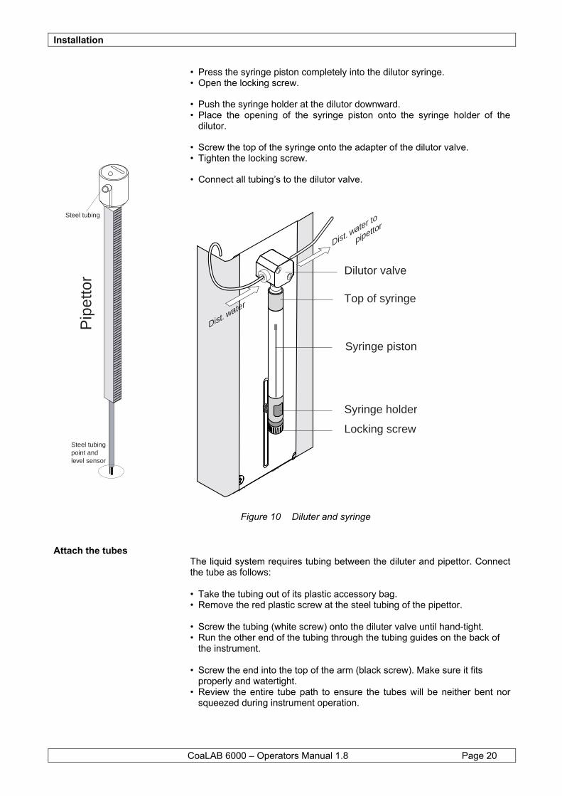
• Press the syringe piston completely into the dilutor syringe. • Open the locking screw. • Push the syringe holder at the dilutor downward. • Place the opening of the syringe piston onto the syringe holder of the
dilutor. • Screw the top of the syringe onto the adapter of the dilutor valve. • Tighten the locking screw. • Connect all tubing’s to the dilutor valve.
Figure 10 Diluter and syringe
Attach the tubes The liquid system requires tubing between the diluter and pipettor. Connect the tube as follows: • Take the tubing out of its plastic accessory bag. • Remove the red plastic screw at the steel tubing of the pipettor. • Screw the tubing (white screw) onto the diluter valve until hand-tight. • Run the other end of the tubing through the tubing guides on the back of
the instrument. • Screw the end into the top of the arm (black screw). Make sure it fits
properly and watertight. • Review the entire tube path to ensure the tubes will be neither bent nor
squeezed during instrument operation.
Steel tubing
Steel tubingpoint andlevel sensor
Pip
etto
r
Dilutor valve
Top of syringe
Locking screw
Syringe holder
Dist. water
Dist. water to
pipettor
Syringe piston
Installation
CoaLAB 6000 – Operators Manual 1.8 Page 21
5.1.4.2 Connect the Liquid System Containers
• Place the distilled water container (with the green label) and the empty
waste water container (with the red label) to the left rear of the system. Fill the distilled water container with at least 1 Liter of distilled water.
• Place the colour-coded sensors into the appropriate containers (green for
dist. water, red for waste water). Ensure there are no air bubbles in the tubing of the distilled water container, or in the container itself.
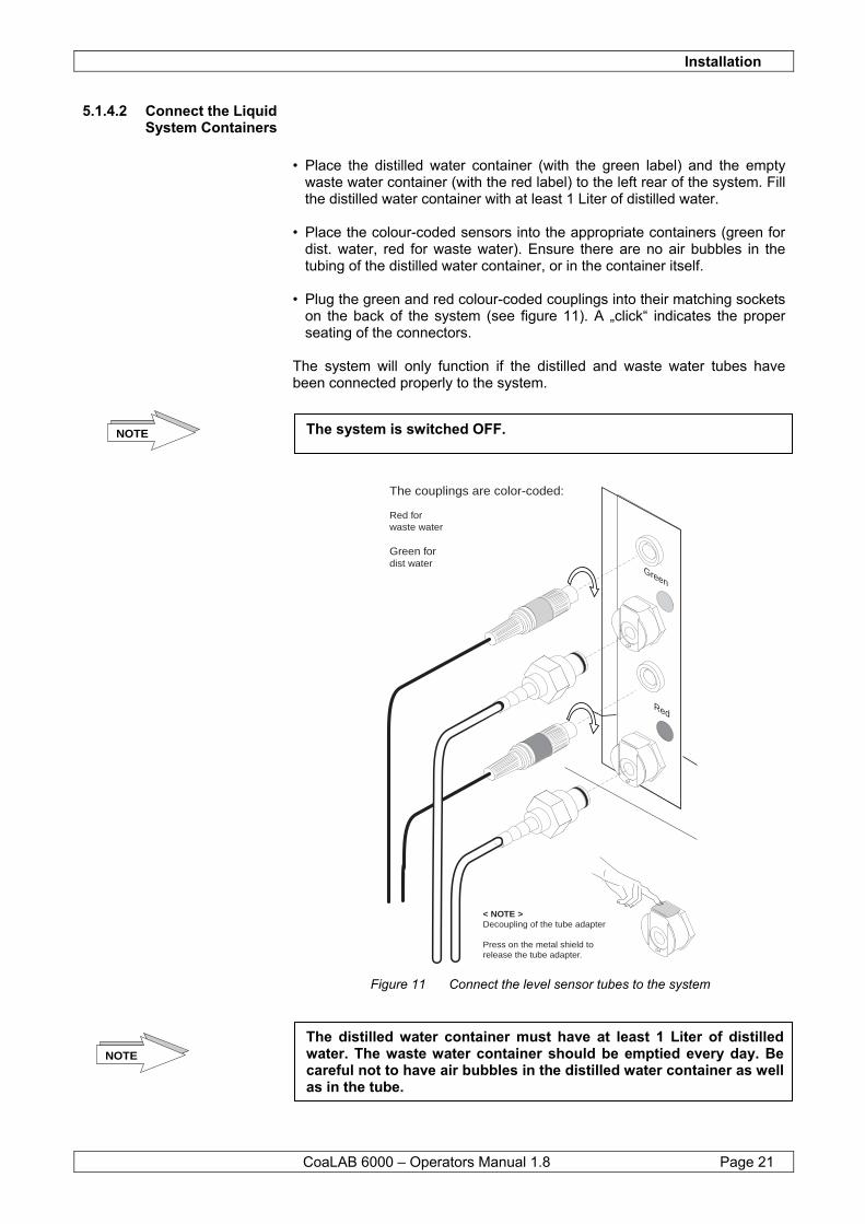
• Plug the green and red colour-coded couplings into their matching sockets
on the back of the system (see figure 11). A „click“ indicates the proper seating of the connectors.
The system will only function if the distilled and waste water tubes have been connected properly to the system.
Figure 11 Connect the level sensor tubes to the system
NOTE The system is switched OFF.
The distilled water container must have at least 1 Liter of distilled water. The waste water container should be emptied every day. Be careful not to have air bubbles in the distilled water container as well as in the tube.
NOTE
Green
Red
The couplings are color-coded:
Red forwaste water
Green for dist water
< NOTE >Decoupling of the tube adapter
Press on the metal shield torelease the tube adapter.
Installation
CoaLAB 6000 – Operators Manual 1.8 Page 22
Container
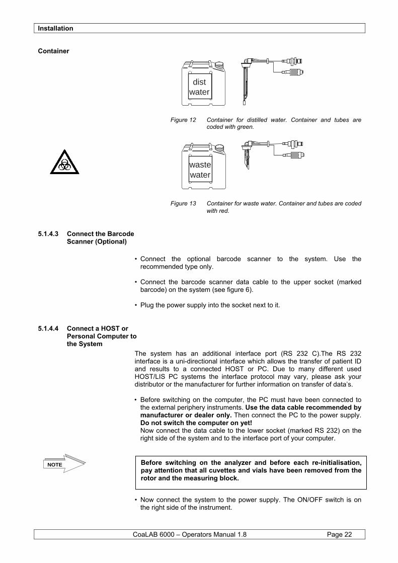
Figure 12 Container for distilled water. Container and tubes are coded with green.
Figure 13 Container for waste water. Container and tubes are coded with red.
5.1.4.3 Connect the Barcode Scanner (Optional)
• Connect the optional barcode scanner to the system. Use the
recommended type only. • Connect the barcode scanner data cable to the upper socket (marked
barcode) on the system (see figure 6). • Plug the power supply into the socket next to it.
5.1.4.4 Connect a HOST or Personal Computer to the System
The system has an additional interface port (RS 232 C).The RS 232 interface is a uni-directional interface which allows the transfer of patient ID and results to a connected HOST or PC. Due to many different used HOST/LIS PC systems the interface protocol may vary, please ask your distributor or the manufacturer for further information on transfer of data’s. • Before switching on the computer, the PC must have been connected to
the external periphery instruments. Use the data cable recommended by manufacturer or dealer only. Then connect the PC to the power supply. Do not switch the computer on yet!
Now connect the data cable to the lower socket (marked RS 232) on the right side of the system and to the interface port of your computer.
• Now connect the system to the power supply. The ON/OFF switch is on
the right side of the instrument.
distwater
wastewater
Before switching on the analyzer and before each re-initialisation,pay attention that all cuvettes and vials have been removed from the rotor and the measuring block.
NOTE
Installation
CoaLAB 6000 – Operators Manual 1.8 Page 23
• After complete installation the instrument and, possibly, the computer can be switched on and off accordingly.
See figure 6 Power ON/OFF, Power filter.
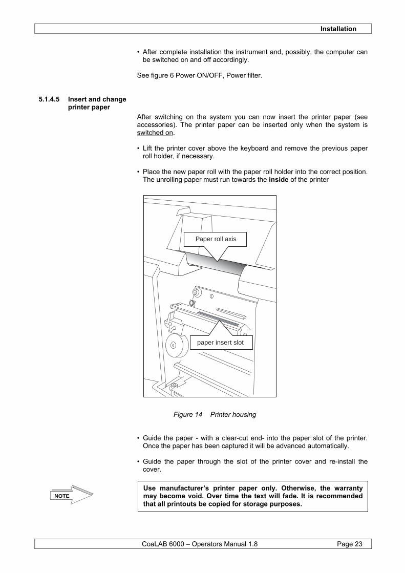
5.1.4.5 Insert and change printer paper
After switching on the system you can now insert the printer paper (see accessories). The printer paper can be inserted only when the system is switched on. • Lift the printer cover above the keyboard and remove the previous paper
roll holder, if necessary. • Place the new paper roll with the paper roll holder into the correct position.
The unrolling paper must run towards the inside of the printer
Figure 14 Printer housing • Guide the paper - with a clear-cut end- into the paper slot of the printer.
Once the paper has been captured it will be advanced automatically. • Guide the paper through the slot of the printer cover and re-install the
cover.
Paper roll axis
paper insert slot
Use manufacturer’s printer paper only. Otherwise, the warranty may become void. Over time the text will fade. It is recommended that all printouts be copied for storage purposes.
NOTE
Installation
CoaLAB 6000 – Operators Manual 1.8 Page 24
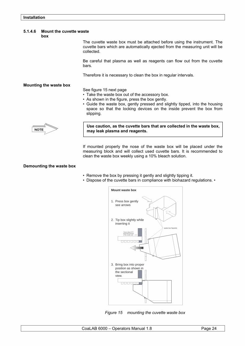
5.1.4.6 Mount the cuvette waste box
The cuvette waste box must be attached before using the instrument. The cuvette bars which are automatically ejected from the measuring unit will be collected. Be careful that plasma as well as reagents can flow out from the cuvette bars. Therefore it is necessary to clean the box in regular intervals.
Mounting the waste box See figure 15 next page • Take the waste box out of the accessory box. • As shown in the figure, press the box gently. • Guide the waste box, gently pressed and slightly tipped, into the housing
space so that the locking devices on the inside prevent the box from slipping.
If mounted properly the nose of the waste box will be placed under the measuring block and will collect used cuvette bars. It is recommended to clean the waste box weekly using a 10% bleach solution.
Demounting the waste box • Remove the box by pressing it gently and slightly tipping it. • Dispose of the cuvette bars in compliance with biohazard regulations. •
Figure 15 mounting the cuvette waste box
NOTEUse caution, as the cuvette bars that are collected in the waste box, may leak plasma and reagents.
���
yyy
���
yyy
Thermo block 37˚CMovement directionof the cuvette rack --->>>
waste box fixpoints
Mount waste box
1. Press box gentlysee arrows
2. Tip box slightly whileinserting it
3. Bring box into properposition as shown inthe sectionalview.
Installation
CoaLAB 6000 – Operators Manual 1.8 Page 25
5.2 Instrument control Card (ICC)
The manufacturer recommends to fill in the Instrument Control Card (see attachment) of each system after its initial installation and to return it to the manufacturer within four weeks. With this Instrument Control Card the manufacturer will register your system. The customer confirms proper receipt, functioning and completeness of the delivered system. The document is enclosed.
5.3 Language Setup The analyzer is pre-set to the English language. If you want to change the language follow section 6.4.7 Language.
The Instrument Control Card is the basis for any warranty claims. Possible claims can only be called for if the Instrument Control Card had been returned to the manufacturer after the initial installation of the system.
NOTE
Operation
CoaLAB 6000 – Operators Manual 1.8 Page 26
6 Operation This section describes how to routinely operate the system as well as information on quality control of coagulation measurements. Furthermore you will find hints to possible failures and troubleshooting.
Training Onsite training courses are offered for this instrument. For additional information contact your distributor.
Safety precautions Thoroughly review the Hazard and Precautions section of this manual before proceeding.
6.1 Routine Operation <1 ROUTINE MENU>
The system will be ready for coagulation analysis after initial set-up has been completed, see section 6.4 General Setting (SETUP MENU). The following descriptions explain the ROUTINE MENU and give an insight into safe coagulation analysis. In the ROUTINE MENU you can select between three different methods. You can use nearly all well-known PT / aPTT and Fibrinogen reagents on the system. Please note that due to the large variety of coagulation reagents on today’s markets only a certain number of reagents have been checked and adjusted to the system. See section 8.7 Adaptation of coagulation reagents for further information.
Preparing routine operation - The instrument is connected to the power supply. - The distilled water container is filled with water (without bubbles) and
connected to the system. - The waste water container is empty and connected to the system. - The waste box is cleared of cuvette bars. - All tubes have been properly connected, and are neither squeezed nor
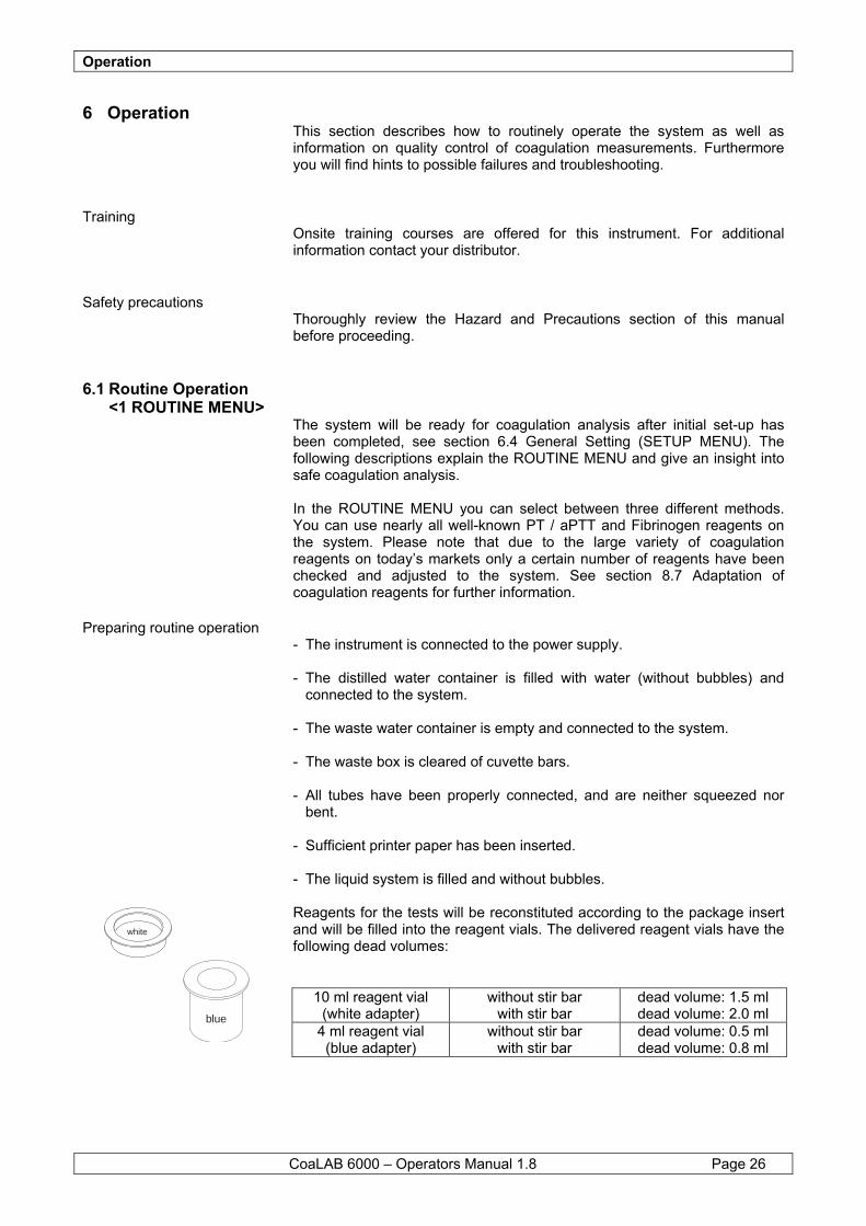
bent. - Sufficient printer paper has been inserted. - The liquid system is filled and without bubbles. Reagents for the tests will be reconstituted according to the package insert and will be filled into the reagent vials. The delivered reagent vials have the following dead volumes:
10 ml reagent vial (white adapter)
without stir bar with stir bar
dead volume: 1.5 ml dead volume: 2.0 ml
4 ml reagent vial (blue adapter)
without stir bar with stir bar
dead volume: 0.5 ml dead volume: 0.8 ml
blue
white

Operation
CoaLAB 6000 – Operators Manual 1.8 Page 27
6.1.1 Switch ON the system • Switch the instrument on by setting the power switch to the position I =
ON. The display shows the instrument name and checks all internal modules automatically (the pipettor moves to the washing station).
Diverse displays ... User dialogue display of the system
Then all system modules will be initialised. The following data will be printed:
C2820501 V1.04 04/22/02 Ser. No. / SW-Version / Release 07.05.2002 08:55 Date / Time
The instrument is ready for operation. • Use the arrow keys (</>) to select <1 ROUTINE MENU> in the MAIN
MENU.
MAIN MENU: < 1 ROUTINE MENU >
• Press the ENTER-key to confirm. The following display appears:
MAIN MENU: < 1 Erase joblist >
6.1.2 Rinsing with distilled water
For transport protection reasons the system has been delivered in dry condition, without any liquids. Before measuring with the system it is necessary to perform a rinsing process and fill all system modules with liquid (pumps, dilutor and tubing’s). This procedure also removes any air bubbles from the tubing system and the dilutor tubing. You can now check whether all tube and screw connections have been installed properly. Should you notice any leaking, tighten the connections to the point that they are watertight. • Use the arrow keys (</>) to select < 8 Maintenance > in the ROUTINE
MENU.
ROUTINE MENU: < 8 Maintenance >
• Press ENTER to confirm and rinse the pipetting system of the system.
The instrument must be free of cuvette bars, sample and reagent vials. NOTE
Operation
CoaLAB 6000 – Operators Manual 1.8 Page 28
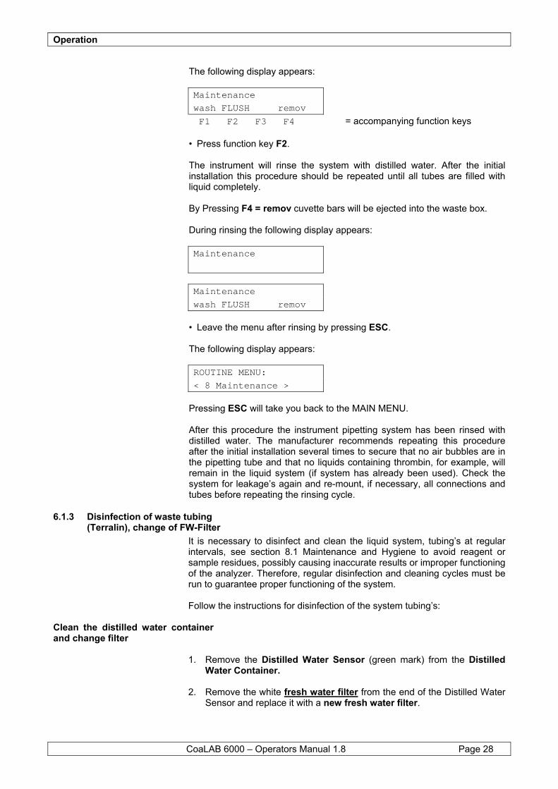
The following display appears:
Maintenance wash FLUSH remov F1 F2 F3 F4 = accompanying function keys
• Press function key F2. The instrument will rinse the system with distilled water. After the initial installation this procedure should be repeated until all tubes are filled with liquid completely. By Pressing F4 = remov cuvette bars will be ejected into the waste box. During rinsing the following display appears:
Maintenance
Maintenance wash FLUSH remov
• Leave the menu after rinsing by pressing ESC. The following display appears:
ROUTINE MENU: < 8 Maintenance >
Pressing ESC will take you back to the MAIN MENU. After this procedure the instrument pipetting system has been rinsed with distilled water. The manufacturer recommends repeating this procedure after the initial installation several times to secure that no air bubbles are in the pipetting tube and that no liquids containing thrombin, for example, will remain in the liquid system (if system has already been used). Check the system for leakage’s again and re-mount, if necessary, all connections and tubes before repeating the rinsing cycle.
6.1.3 Disinfection of waste tubing (Terralin), change of FW-Filter
It is necessary to disinfect and clean the liquid system, tubing’s at regular intervals, see section 8.1 Maintenance and Hygiene to avoid reagent or sample residues, possibly causing inaccurate results or improper functioning of the analyzer. Therefore, regular disinfection and cleaning cycles must be run to guarantee proper functioning of the system. Follow the instructions for disinfection of the system tubing’s:
Clean the distilled water container and change filter
1. Remove the Distilled Water Sensor (green mark) from the Distilled
Water Container. 2. Remove the white fresh water filter from the end of the Distilled Water
Sensor and replace it with a new fresh water filter.
Operation
CoaLAB 6000 – Operators Manual 1.8 Page 29
3. Empty the Distilled Water Container and clean the inside using a 70% alcohol solution.
4. Rinse the Distilled Water Container thoroughly with distilled water to
remove any traces of the alcohol solution. 5. Refill the Distilled Water Container and return the Distilled Water
Sensor to the container.
Disinfection of Wash Station and Waste tubing with Cleaning Solution
6. Make a working solution of Cleaning Solution. Fill 2 Liters of distilled
water into the Cleaning Solution Container (white label) and add 20 ml of concentrated Cleaning Solution. Swirl gently.
7. Place the Waste Water Container carrying the Waste Level Sensor
(red label, sensor) beside or behind the analyzer on the same height level. The container may not be placed underneath the analyzer. Make sure the waste tubing (red marked) and the electrical plug of the waste tubing are correctly connected to the fluid panel of the back side of the analyzer.
8. Take out 4ml of the diluted working Cleaning Solution from the
Cleaning Container using a standard commercial pipette, e.g. Eppendorf.
9. Guide the pipette over the Wash Station, located in the center of the
reagent and sample rotor. 10. Dispense the diluted Cleaning Solution out of the pipette into the wash
station. Repeat this process until you have added 4ml into the Wash Station. Leave the working Cleaning Solution in the Wash Station for at least 2 min.
Flush after cleaning After the disinfection/cleaning cycle with Cleaning Solution it is absolutely necessary to rinse the liquid system with distilled water to ensure that no Cleaning Solution may remain in the liquid system at all.
Do not disconnect any of the level sensor tubing’s (red/green) and electrical plugs at the fluid panel at the back side of the analyzer. NOTE
Make sure that neither the steel needle nor the level sensor of the probe will be damaged or bent during this operation. The system may not be in operation, moving.
Make sure the Cleaning Solution inside the Wash Station remains on the same level. It may not disappear inside the Wash Station. In this event place the Waste Water Container on a higher level, meaning above the height of the wash station of the analyzer and repeat adding the Cleaning Solution into the Wash Station. Further make certain not to overflow the wash station to avoid any liquid flowing into the sample/reagent rotor.
NOTE
NOTE
Operation
CoaLAB 6000 – Operators Manual 1.8 Page 30
Follow the instructions to rinse the system with distilled water: 11. Make sure the Distilled Water Sensor is equipped with a NEW fresh
water filter and the Distilled Water Sensor is placed correctly in the Distilled Water Container.
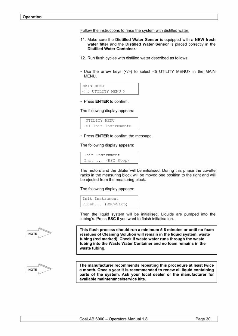
12. Run flush cycles with distilled water described as follows:
• Use the arrow keys (</>) to select <5 UTILITY MENU> in the MAIN
MENU. MAIN MENU < 5 UTILITY MENU >
• Press ENTER to confirm. The following display appears:
UTILITY MENU <1 Init Instrument>
• Press ENTER to confirm the message. The following display appears: Init Instrument Init ... (ESC=Stop)
The motors and the diluter will be initialised. During this phase the cuvette racks in the measuring block will be moved one position to the right and will be ejected from the measuring block. The following display appears: Init Instrument Flush... (ESC=Stop)
Then the liquid system will be initialised. Liquids are pumped into the tubing’s. Press ESC if you want to finish initialisation.
This flush process should run a minimum 5-8 minutes or until no foam residues of Cleaning Solution will remain in the liquid system, waste tubing (red marked). Check if waste water runs through the waste tubing into the Waste Water Container and no foam remains in the waste tubing.
The manufacturer recommends repeating this procedure at least twice a month. Once a year it is recommended to renew all liquid containing parts of the system. Ask your local dealer or the manufacturer for available maintenance/service kits.
NOTE
NOTE
Operation
CoaLAB 6000 – Operators Manual 1.8 Page 31
6.1.4 Rinsing with Washing Solution
In the ROUTINE MENU you can choose to clean the pipetting system of the instrument with an extra Washing Solution. This is especially recommended after the use of reagents containing thrombin, such as Fibrinogen. The system disposes of an automatically wash cycle if Thrombin containing reagents, e.g. Fibrinogen are being used. Once the reagents are introduced, see section 6.1.5 and are requested to run in a joblist, section 6.1.7 the system automatically washes the system with washing solution after the use of such thrombin containing reagents. Follow the instructions to wash the system: • Use the arrow keys (</>) to select < 8 Maintenance > in the ROUTINE
MENU. ROUTINE MENU
< 8 Maintenance >
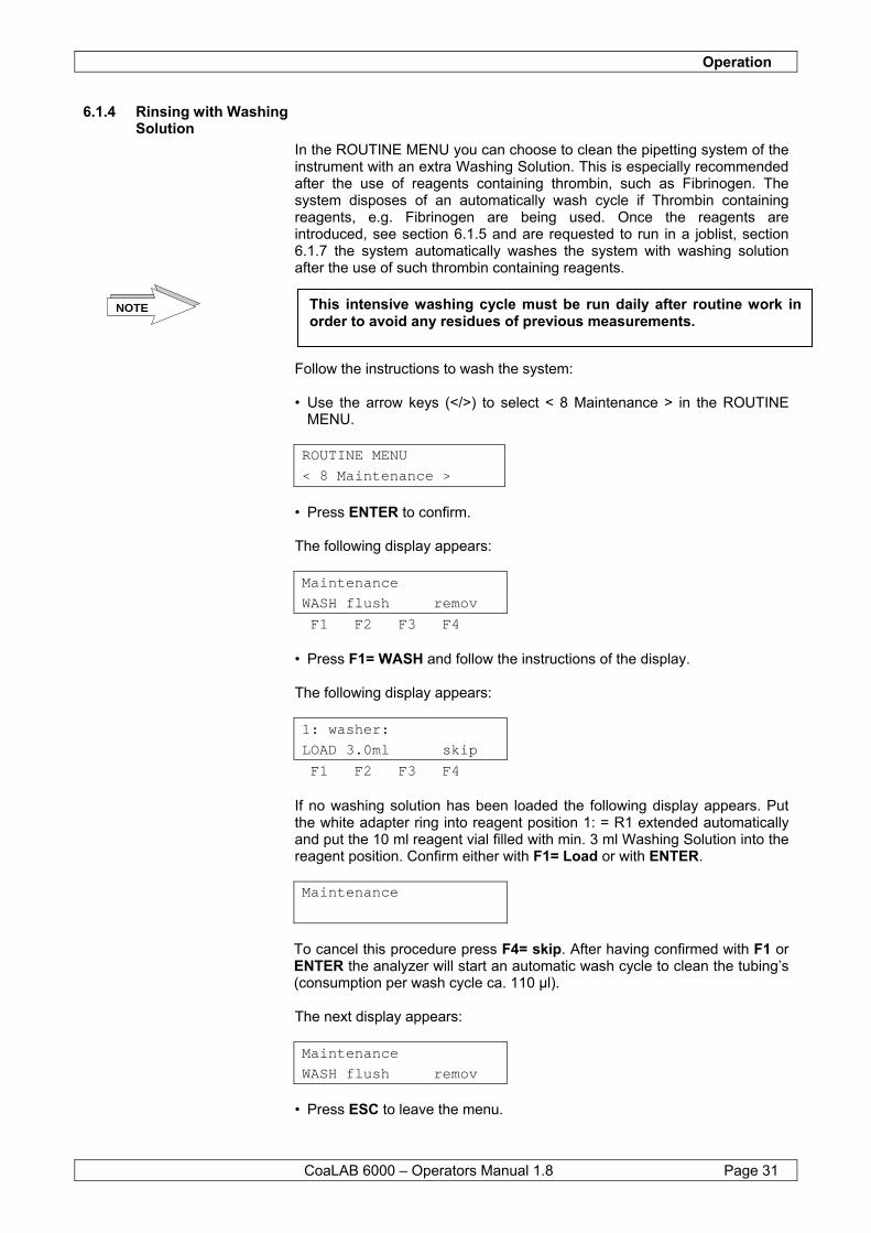
• Press ENTER to confirm. The following display appears:
Maintenance WASH flush remov F1 F2 F3 F4
• Press F1= WASH and follow the instructions of the display. The following display appears:
1: washer: LOAD 3.0ml skip F1 F2 F3 F4
If no washing solution has been loaded the following display appears. Put the white adapter ring into reagent position 1: = R1 extended automatically and put the 10 ml reagent vial filled with min. 3 ml Washing Solution into the reagent position. Confirm either with F1= Load or with ENTER. Maintenance
To cancel this procedure press F4= skip. After having confirmed with F1 or ENTER the analyzer will start an automatic wash cycle to clean the tubing’s (consumption per wash cycle ca. 110 µl). The next display appears:
Maintenance WASH flush remov
• Press ESC to leave the menu.
This intensive washing cycle must be run daily after routine work in order to avoid any residues of previous measurements.
NOTE
Operation
CoaLAB 6000 – Operators Manual 1.8 Page 32
The following display appears: ROUTINE MENU
< 8 Maintenance >
The system has now been cleaned with Washing Solution. If necessary, this procedure can be repeated. Press ESC to get back to the upper menu level.
6.1.5 Loading and unloading reagents
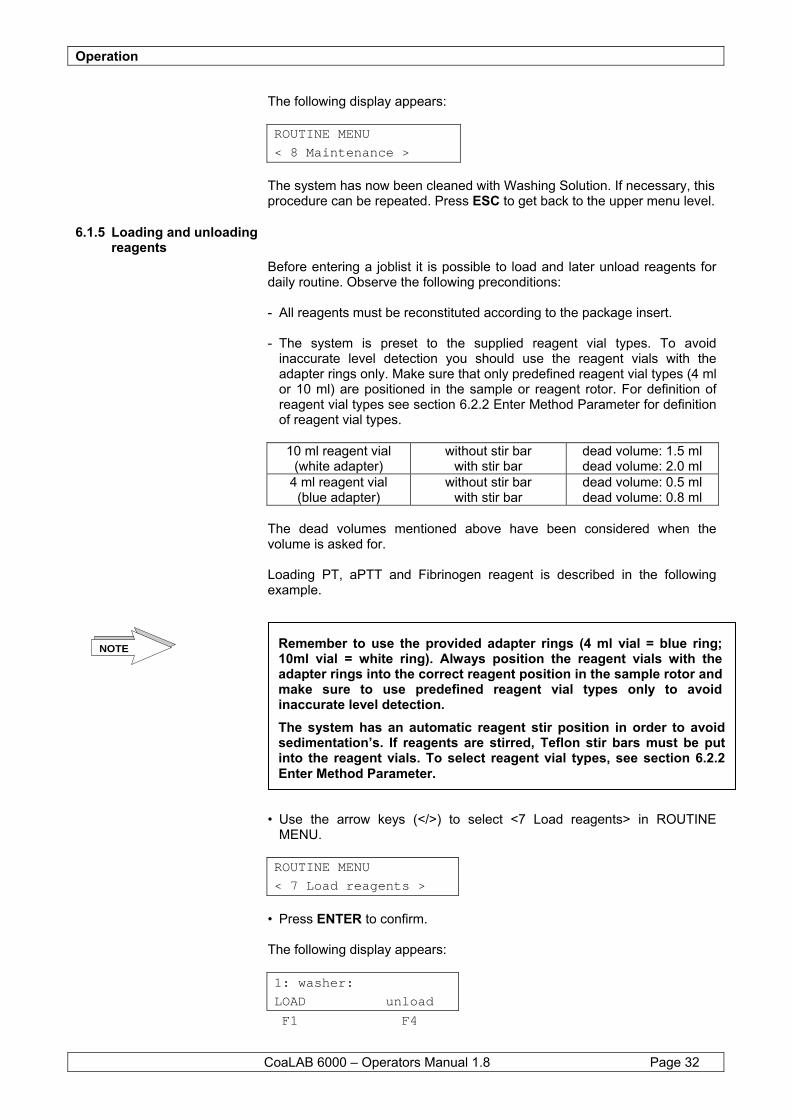
Before entering a joblist it is possible to load and later unload reagents for daily routine. Observe the following preconditions: - All reagents must be reconstituted according to the package insert. - The system is preset to the supplied reagent vial types. To avoid
inaccurate level detection you should use the reagent vials with the adapter rings only. Make sure that only predefined reagent vial types (4 ml or 10 ml) are positioned in the sample or reagent rotor. For definition of reagent vial types see section 6.2.2 Enter Method Parameter for definition of reagent vial types.
10 ml reagent vial
(white adapter) without stir bar
with stir bar dead volume: 1.5 ml dead volume: 2.0 ml
4 ml reagent vial (blue adapter)
without stir bar with stir bar
dead volume: 0.5 ml dead volume: 0.8 ml
The dead volumes mentioned above have been considered when the volume is asked for. Loading PT, aPTT and Fibrinogen reagent is described in the following example. • Use the arrow keys (</>) to select <7 Load reagents> in ROUTINE
MENU. ROUTINE MENU
< 7 Load reagents >
• Press ENTER to confirm. The following display appears:
1: washer: LOAD unload F1 F4
Remember to use the provided adapter rings (4 ml vial = blue ring; 10ml vial = white ring). Always position the reagent vials with the adapter rings into the correct reagent position in the sample rotor and make sure to use predefined reagent vial types only to avoid inaccurate level detection. The system has an automatic reagent stir position in order to avoid sedimentation’s. If reagents are stirred, Teflon stir bars must be put into the reagent vials. To select reagent vial types, see section 6.2.2Enter Method Parameter.
NOTE
Operation
CoaLAB 6000 – Operators Manual 1.8 Page 33
The reagent position for the Washing Solution will be extended automatically. Should you have loaded Washing Solution already, the above display appears. • Press F1 to confirm loading.
The following display appears:
2: Buffer: 9999992 LOAD skip
The sample rotor position will be extended automatically. Load the sample rotor with Buffer in position 2: = R2 and confirm with F1. If you want to skip over this position and not load Buffer press F4. The following display appears:
3: FBG 8888 LOAD skip
The sample rotor position will be extended automatically. Load the sample rotor with Fibrinogen reagent in position 3: = R3 and confirm with F1. If you want to skip over this position and not load Fibrinogen press F4. The following display appears:
4: CaCl2 88888 LOAD skip
The sample rotor position will be extended automatically. Load the sample rotor with Calcium Chloride in position 4: = R4 and confirm with F1. If you want to skip over this position and not load Calcium Chloride press F4. The following display appears:
5: aPTT 99999995 LOAD skip
By pressing F4 ‘remove’ you inform the system that you have removed reagent and/or washing solution from the sample rotor. ‘Remove’ will always be displayed if you have loaded the sample rotor with reagents and/or washing solution beforehand. Once the sample rotor has been loaded with reagents and/or washing solution ‘remove’ will be displayed to ‘unload’ the sample rotor. If ‘skip’ is displayed instead of ‘remove’ you can press F4 to skip over loading with reagent and/or Washing Solution. Remember however, that the analyzer cannot run measurements or start cleaning cycles ifreagents and/or Washing Solution have not been loaded. This message will always be displayed when no reagents and/or Washing Solution have been loaded to the sample rotor.
NOTE

Operation
CoaLAB 6000 – Operators Manual 1.8 Page 34
The sample rotor position will be extended automatically. Load the sample rotor with aPTT reagent in position 5: = R5 and confirm with F1. If you want to skip over this position and not load aPTT reagent press F4. The following display appears:
6: PT 88888 LOAD skip
The sample rotor position will be extended automatically. Load the sample rotor with PT reagent in position 6: = R6 and confirm with F1. If you want to skip over this position and not load PT reagent press F4. After all reagents have been positioned on the sample rotor the following display appears. ROUTINE MENU
< 7 Load reagents >
• Press ESC to get back into the MAIN MENU.
6.1.6 Delete joblist, delete samples
If you want to delete a joblist from the memory follow the instructions: • Use the arrow keys (</>) to select <1 Erase joblist > in the ROUTINE
MENU. The following display appears: ROUTINE MENU
< 1 Erase joblist >
Press ENTER to confirm. The following display appears: Really erase joblist?
YES no
If you want to delete the joblist confirm with F1 = YES. If you do not want to delete it, press F2 = NO. Confirm with F1. The following display appears: Remove samples 1-9
and close cover
• Remove primary tubes 1 to 9 from the sample positions extended
automatically and confirm with ENTER. If more than 9 primary tubes are in the sample rotor the following message appears: Remove samples 10-
and close cover
Operation
CoaLAB 6000 – Operators Manual 1.8 Page 35
• Remove the remaining primary tubes 10 - 18 and confirm with ENTER. The following display appears: ROUTINE MENU
< 1 Erase joblist >
• Press ESC to get back into the MAIN MENU.
6.1.7 Enter a new joblist Before entering a joblist you must define whether single or double determinations shall be made, see section 6.2.2.1 The following examples show how a joblist is to be entered:
Example 1: 01 = Sample 1 S-ID: 30001 = consecutive no. PT and APTT =
test to be measured Example 2: 02 = Sample 2
S-ID: 30002 = consecutive no PT, APTT, FBG = test to be measured
Example 3: 03 = Sample 3
S-ID: 123 = individual no PT = test to be measured
Example 1: • Use the arrow keys (</>) to select < 2 Insert sample > in the ROUTINE
MENU. ROUTINE MENU
< 2 Insert sample >
• Press ENTER to confirm. The following display appears:
01 S-ID: 30001 pt aptt fbg all F1 F2 F3 F4
The sample rotor will automatically advance to the position to be loaded with sample 1 (01 S-ID:). Load the sample rotor with the first primary tube and select the tests with keys F1-F4. In this case the tests pt=F1 and aptt=F2 have been selected. The following display appears:
01 S-ID: 30001 pt APTT fbg all
After the tests have been selected they will appear in capital letters. • Press ENTER to confirm.
Operation
CoaLAB 6000 – Operators Manual 1.8 Page 36
The following display appears:
Example 2 02 S-ID: 30002 pt aptt fbg all
The sample rotor will automatically advance to the position to be loaded with sample 2 (02 S-ID:). Load the sample rotor with the second primary tube and select the tests with keys F1-F4. In this case the tests pt, aptt and fbg have been selected, i.e. all = F4. • Press ENTER to confirm. The following display appears:
Example 3 03 S-ID: 123 pt aptt fbg all
The sample rotor will automatically advance to the position to be loaded with sample 3 (03 S-ID:). Load the sample rotor with the third primary tube and select the tests with keys F1-F4. In this case the test pt=F1 has been selected. If you want to change the patient ID press the left arrow key (<) until the patient ID is no longer displayed. You can now enter the individual ID, here 123. • Press ENTER to confirm. The following display appears:
04 S-ID: 30003 pt aptt fbg all
The sample rotor will extend automatically the position to be loaded with sample 4 (04 S-ID:). Repeat this procedure to insert more patient ID´s. Press ESC to leave this Menu. The analyzer offers two possibilities to enter patient ID’s. If no ID is entered the system will automatically assign consecutive numbers. 1.) Enter the patient ID manually. Using the number keys (0-9), enter the
patient ID up to 10 digits. 2) Enter the patient ID by using the barcode scanner. Press the button on
the barcode scanner and direct the scanner window to the barcode label of the primary tube. Continue pressing the button until a beep confirms entry of ID.
Press ESC to leave the Menu.
A large number of barcodes can be used. If the system does not accept a certain barcode contact the manufacturer or enter the patient ID manually.
NOTE
Operation
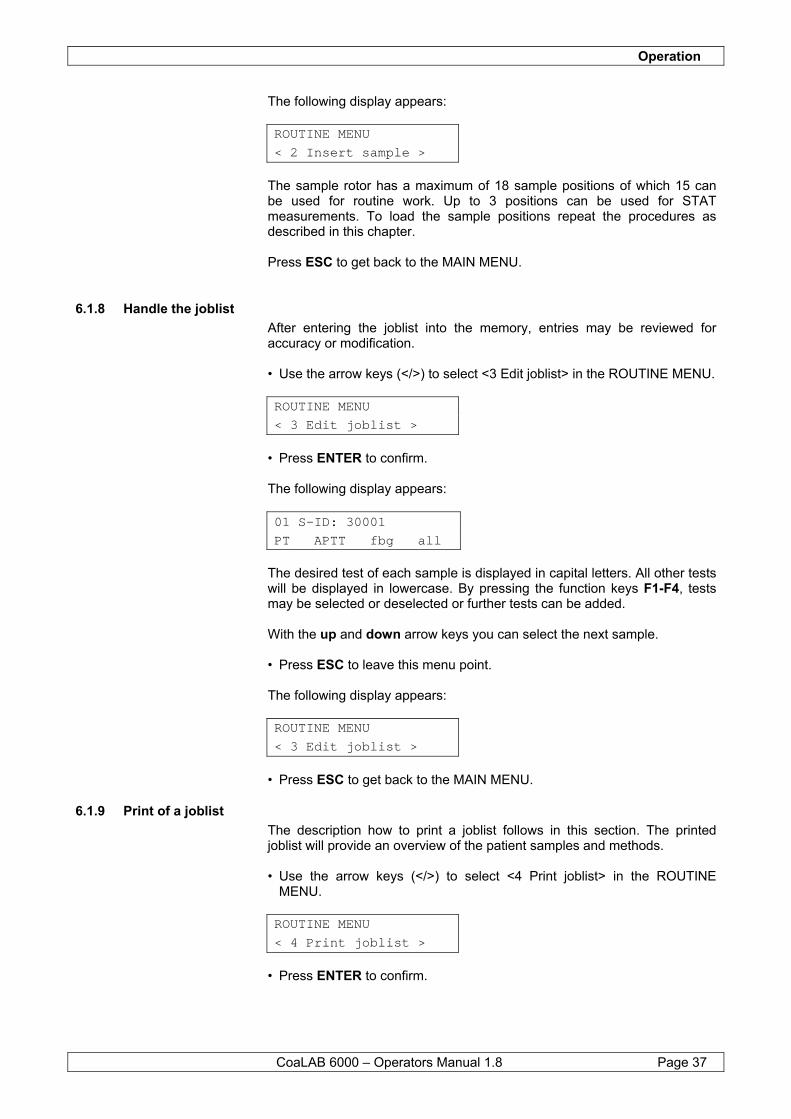
CoaLAB 6000 – Operators Manual 1.8 Page 37
The following display appears: ROUTINE MENU
< 2 Insert sample >
The sample rotor has a maximum of 18 sample positions of which 15 can be used for routine work. Up to 3 positions can be used for STAT measurements. To load the sample positions repeat the procedures as described in this chapter. Press ESC to get back to the MAIN MENU.
6.1.8 Handle the joblist After entering the joblist into the memory, entries may be reviewed for accuracy or modification. • Use the arrow keys (</>) to select <3 Edit joblist> in the ROUTINE MENU. ROUTINE MENU
< 3 Edit joblist >
• Press ENTER to confirm. The following display appears:
01 S-ID: 30001 PT APTT fbg all
The desired test of each sample is displayed in capital letters. All other tests will be displayed in lowercase. By pressing the function keys F1-F4, tests may be selected or deselected or further tests can be added. With the up and down arrow keys you can select the next sample. • Press ESC to leave this menu point. The following display appears: ROUTINE MENU
< 3 Edit joblist >
• Press ESC to get back to the MAIN MENU.
6.1.9 Print of a joblist The description how to print a joblist follows in this section. The printed joblist will provide an overview of the patient samples and methods. • Use the arrow keys (</>) to select <4 Print joblist> in the ROUTINE
MENU. ROUTINE MENU
< 4 Print joblist >
• Press ENTER to confirm.
Operation
CoaLAB 6000 – Operators Manual 1.8 Page 38
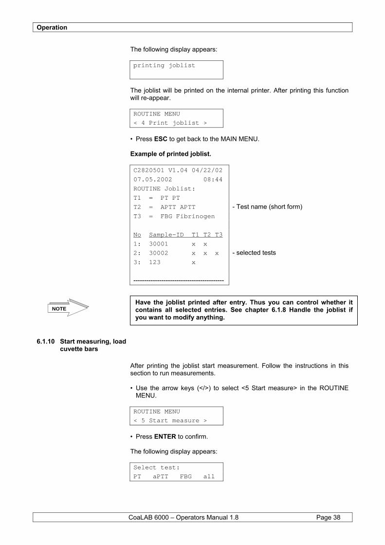
The following display appears: printing joblist
The joblist will be printed on the internal printer. After printing this function will re-appear. ROUTINE MENU
< 4 Print joblist >
• Press ESC to get back to the MAIN MENU. Example of printed joblist. C2820501 V1.04 04/22/02 07.05.2002 08:44 ROUTINE Joblist: T1 = PT PT T2 = APTT APTT - Test name (short form) T3 = FBG Fibrinogen No Sample-ID T1 T2 T3 1: 30001 x x 2: 30002 x x x - selected tests 3: 123 x ------------------------------------------
6.1.10 Start measuring, load cuvette bars
After printing the joblist start measurement. Follow the instructions in this section to run measurements. • Use the arrow keys (</>) to select <5 Start measure> in the ROUTINE
MENU. ROUTINE MENU
< 5 Start measure >
• Press ENTER to confirm. The following display appears: Select test:
PT aPTT FBG all
Have the joblist printed after entry. Thus you can control whether it contains all selected entries. See chapter 6.1.8 Handle the joblist if you want to modify anything.
NOTE
Operation
CoaLAB 6000 – Operators Manual 1.8 Page 39
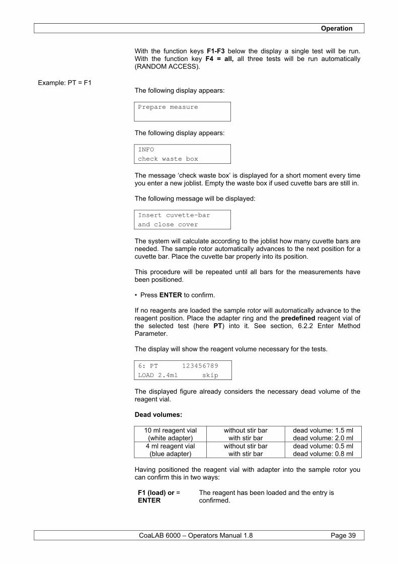
With the function keys F1-F3 below the display a single test will be run. With the function key F4 = all, all three tests will be run automatically (RANDOM ACCESS).
Example: PT = F1 The following display appears: Prepare measure
The following display appears: INFO
check waste box
The message ‘check waste box’ is displayed for a short moment every time you enter a new joblist. Empty the waste box if used cuvette bars are still in. The following message will be displayed: Insert cuvette-bar
and close cover
The system will calculate according to the joblist how many cuvette bars are needed. The sample rotor automatically advances to the next position for a cuvette bar. Place the cuvette bar properly into its position. This procedure will be repeated until all bars for the measurements have been positioned. • Press ENTER to confirm. If no reagents are loaded the sample rotor will automatically advance to the reagent position. Place the adapter ring and the predefined reagent vial of the selected test (here PT) into it. See section, 6.2.2 Enter Method Parameter. The display will show the reagent volume necessary for the tests.
6: PT 123456789 LOAD 2.4ml skip
The displayed figure already considers the necessary dead volume of the reagent vial. Dead volumes:
10 ml reagent vial (white adapter)
without stir bar with stir bar
dead volume: 1.5 ml dead volume: 2.0 ml
4 ml reagent vial (blue adapter)
without stir bar with stir bar
dead volume: 0.5 ml dead volume: 0.8 ml
Having positioned the reagent vial with adapter into the sample rotor you can confirm this in two ways: F1 (load) or = ENTER
The reagent has been loaded and the entry is confirmed.

Operation
CoaLAB 6000 – Operators Manual 1.8 Page 40
F4 (skip) =
The reagent has not been loaded, the entry was not confirmed.
• In this case press F1 or ENTER to confirm.
The instrument will check the reagents for sufficient volume. If reagents are missing or the volume is insufficient the following display will appear: For example:
6: PT 123456789 only x.xml of x.xml
Load the missing or insufficient reagent in position R6. Remember the necessary dead volume. • Press ENTER to confirm end of loading. If you do not want to load the missing reagents press ESC. The analyzer will measure as many samples as possible with the available reagents. Samples not measured will be identified with a note on the printout. The following display appears:
Pipettor M-Block 37.4 38.4
The message Pipettor / M-Block indicates the temperature of the measuring block and the pipettor. This message will be displayed until the correct temperature has been reached. The following display appears:
4 PT Samples < No Results available
The system will start measurements. The number (e.g. 4 PT samples) of measurements for each method will be displayed. The results will automatically be printed on the internal printer. The display will show ‘no results available’. The rotating symbol (<) in the upper right hand corner of the display means that the instrument is measuring presently.
Remember that the supplied reagent vials consider sufficient dead volume when calculating the reagent volume. Therefore the reagent volumes are larger than what is actually needed for the tests. Always use the adapter rings and the pre-defined reagent vials as the volume calculation of the reagent will be influenced negatively otherwise.
NOTE
By pressing ESC and thus refuse to load the missing reagents, not all measurements will be worked off your joblist. The system will do all measurements possible with the reagent volume. Follow the steps in this section to work off the remaining measurements.
NOTE
Operation
CoaLAB 6000 – Operators Manual 1.8 Page 41
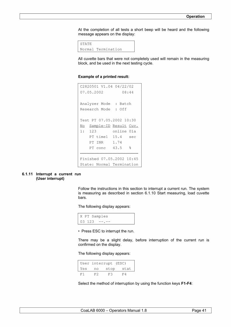
At the completion of all tests a short beep will be heard and the following message appears on the display:
STATE Normal Termination
All cuvette bars that were not completely used will remain in the measuring block, and be used in the next testing cycle. Example of a printed result: C2820501 V1.04 04/22/02 07.05.2002 08:44 Analyzer Mode : Batch Research Mode : Off Test PT 07.05.2002 10:30 No Sample-ID Result Cuv. 1: 123 online 01a PT time1 15.4 sec PT INR 1.74 PT conc 43.5 % --------------------------------------------- Finished 07.05.2002 10:45 State: Normal Termination
6.1.11 Interrupt a current run (User interrupt)
Follow the instructions in this section to interrupt a current run. The system is measuring as described in section 6.1.10 Start measuring, load cuvette bars. The following display appears:
X PT Samples 03 123 --.--
• Press ESC to interrupt the run. There may be a slight delay, before interruption of the current run is confirmed on the display. The following display appears:
User interrupt (ESC) Yes no stop stat F1 F2 F3 F4
Select the method of interruption by using the function keys F1-F4:
Operation
CoaLAB 6000 – Operators Manual 1.8 Page 42
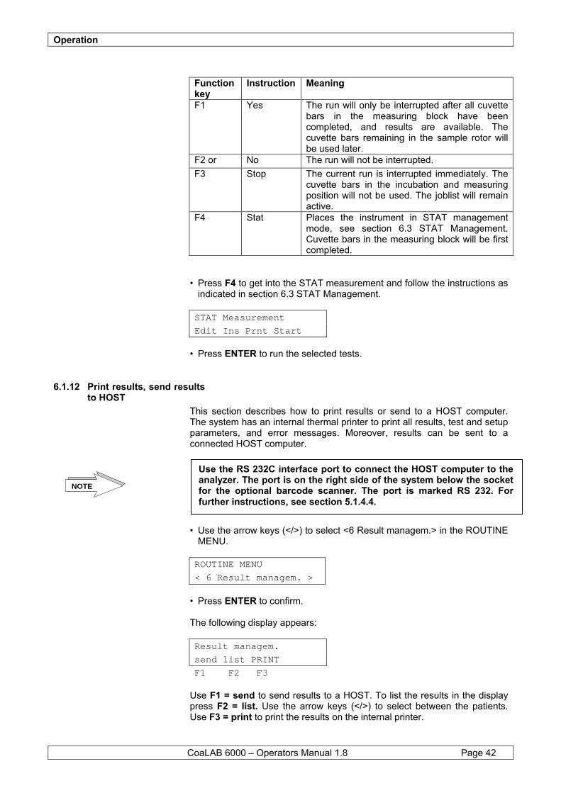
Function key
Instruction Meaning
F1 Yes The run will only be interrupted after all cuvette bars in the measuring block have been completed, and results are available. The cuvette bars remaining in the sample rotor will be used later.
F2 or No The run will not be interrupted. F3 Stop The current run is interrupted immediately. The
cuvette bars in the incubation and measuring position will not be used. The joblist will remain active.
F4 Stat Places the instrument in STAT management mode, see section 6.3 STAT Management. Cuvette bars in the measuring block will be first completed.
• Press F4 to get into the STAT measurement and follow the instructions as
indicated in section 6.3 STAT Management.
STAT Measurement Edit Ins Prnt Start
• Press ENTER to run the selected tests.
6.1.12 Print results, send results to HOST
This section describes how to print results or send to a HOST computer. The system has an internal thermal printer to print all results, test and setup parameters, and error messages. Moreover, results can be sent to a connected HOST computer. • Use the arrow keys (</>) to select <6 Result managem.> in the ROUTINE
MENU. ROUTINE MENU
< 6 Result managem. >
• Press ENTER to confirm. The following display appears:
Result managem. send list PRINT F1 F2 F3
Use F1 = send to send results to a HOST. To list the results in the display press F2 = list. Use the arrow keys (</>) to select between the patients. Use F3 = print to print the results on the internal printer.
Use the RS 232C interface port to connect the HOST computer to the analyzer. The port is on the right side of the system below the socket for the optional barcode scanner. The port is marked RS 232. For further instructions, see section 5.1.4.4.
NOTE
Operation
CoaLAB 6000 – Operators Manual 1.8 Page 43
By pressing F1 = send the following message will appear on the display for a short moment. The results and patient ID´s will be sent to the HOST computer. sending results
By pressing F2 = list the results of each patient and test will be displayed accordingly. Using the arrow keys (</>) will display different patient results per test. Using the arrow keys up/down will display different test results per patient. 123 PT
1 result
After pressing F3 = print the following message will appear on the display for a short moment. The results will be printed on the internal printer. printing results
The following display appears: ROUTINE MENU
< 6 Result managem. >
After sending or printing the ROUTINE MENU will appear again. Press ESC to get back to the MAIN MENU.
6.1.13 Refill liquids, clean containers
It is absolutely necessary to check the level in the distilled water container (green label) constantly and at the same time clean the waste water container regularly. If possible, the distilled water container should have a minimum of 1 litre. Always take care that no bubbles will be in the container. The bubbles might get into the tubing system which would influence level detection. Use Distilled Water (aqua dest.) only! The containers should be checked every time before the system is switched on, before the measurement run at the latest. The waste water container should be cleaned in a regular cycle. See section 8.1 Maintenance and Hygiene for further instructions. The distilled water sensor (marked green) must be placed into the distilled water container (green label) before using the system. This sensor monitors the liquid level in the container and gives an error message if the level is too low. The following error message will be displayed: STATE
Out of system liquid
The current measurement will be interrupted if not enough liquid is in the container during a measurement as the steel tubing cannot be washed.
NOTE
Operation
CoaLAB 6000 – Operators Manual 1.8 Page 44
The following error message will be printed: Finished 07.05.2002 15:45
Status: no system liquid
To refill and clean the distilled water container follow the instructions below: • Ensure that the system is not in a washing cycle or in menu < 5 Start measure >. • Remove the Distilled Water Sensor from the Distilled Water Container. • Empty the Distilled Water Container completely. • Clean the inside of the container using a 70% alcohol solution and rinse it
with distilled water. Avoid any alcohol residues in the container. • Refill the Distilled Water Container with demineralised or distilled water.
Do not use tap water. • Place the Distilled Water Sensor into the container and continue with
routine measurements. • Every time the Distilled Water Container is refilled the Waste Water
Container must be emptied. Always check the liquid levels to avoid unintended interruption of runs.
6.1.14 Empty and clean the waste water container
It is absolutely necessary to check the level in the waste water container (red label) constantly. The container should be checked every time before the system is switched on, before the measurement run at the latest. The waste water sensor (marked red) must be placed into the waste water container (red label) before using the system. This sensor monitors the liquid level in the container and gives an error message if the level is too high. The following error message will be displayed: STATE
Waste bottle full
The following error message will be printed: Finished 07.05.2002 15:45
Status: Waste bottle full
To empty and clean the waste water container follow the instructions below: • Make sure that the instrument is not in a washing cycle or in menu < 5 Start measure >. • Remove the Waste Water Sensor from the Waste Water Container. • Empty the Waste Water Container completely. (See section Hazard and
Precaution)
The current measurement will be interrupted if the level is too high in order to avoid an overflow. NOTE
Operation
CoaLAB 6000 – Operators Manual 1.8 Page 45
• Clean the inside of the Waste Water Container with 70% alcohol solution and rinse it with distilled water. Avoid any alcohol residues in the container.
• Return the Waste Water Sensor to the container and continue with
measurements.
6.2 Enter Test Parameter Follow the instructions to change pre-defined test parameters. The descriptions will lead you through the TEST MENU and will help you to enter test parameters correctly.
6.2.1 Enter Reagent Specific Parameters
In this chapter learn how to enter reagent-specific parameters.
6.2.1.1 Enter a reference curve (PT, for example)
Follow the steps mentioned below to enter a reference curve. Here PT is used as an example since the reference curves for all methods will be entered in the same way. Therefore use the same steps to enter reference curves for the other methods, if necessary. • Use the arrow keys (</>) to select <2 TEST MENU> in the MAIN MENU. MAIN MENU:
< 2 TEST MENU >
• Press ENTER to confirm.
The following display appears: TEST MENU:
PIN
• Enter the PIN code with the number keys (default=11111). The following display appears: TEST MENU:
< 1 Modify test >
The waste water contains patient samples and test reagents and must be treated potentially infectious. Avoid any direct skin contact. Dispose of the waste water in compliance with biohazard and legal provisions.
NOTE
NOTE
Before getting into the TEST MENU it is necessary to enter a number code (PIN). The system number code is preset to 11111 by the manufacturer. Change this code as described in section 6.4.6 Set PIN Code. Remember to note the code down and keep it at a safe place. It should be known to those users only who are authorised to operate the instrument.

Operation
CoaLAB 6000 – Operators Manual 1.8 Page 46
• To change or check test parameters press ENTER to confirm. You can now select from the following display: Select test:
PT aPTT FBG END
• Select method PT by pressing F1. To enter the reference curve for
Fibrinogen press F3 accordingly. Press F4 = END to leave the menu without making any changes.
• Use the arrow keys (</>) until <4 1st Conversion> is displayed. PT PARAMETER:
< 4 1st conversion >
• Press ENTER to confirm. With the arrow keys (</>) choose between the following reference curve types: PT 1st Conversion: selection for: < 1 None > no conversion < 2 Curve regr.> regression < 3 Curve interpol > interpolation
• Use the arrow keys (</>) until < 3 curve interpol > is displayed. • Press ENTER to confirm. The following display appears: Time Val[%]
1 11.5 100.0
The displayed values can be overwritten directly. First enter the time. Press the right arrow key (>) to set the decimal point. Press ENTER to confirm. Enter the % - value with the number keys. Press ENTER to confirm. Use the left arrow key (<) to delete or overwrite. The system checks the reference curve points automatically whether they are plausible, i.e. falling concentration/activity must have rising time values and reverse. If the points are not plausible the system will beep. The following display appears: Time Val[%]
2 14.5 50.0
Enter the 2.reference curve point. Follow the instructions above. A minimum of 2 points must be defined; a maximum of 9 points can be entered. • Press ENTER to confirm the entry.
To enter any additional point after having entered the second or any further point enter 0.0 s for the last time value. The remaining points will not be displayed. To enter more points next time enter the actual time value instead of 0.0 s and the remaining points will be displayed.
NOTE
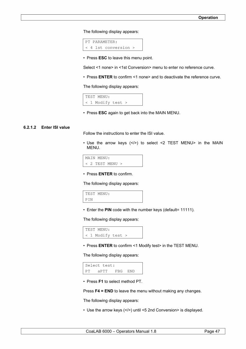
Operation
CoaLAB 6000 – Operators Manual 1.8 Page 47
The following display appears: PT PARAMETER:
< 4 1st conversion >
• Press ESC to leave this menu point. Select <1 none> in <1st Conversion> menu to enter no reference curve. • Press ENTER to confirm <1 none> and to deactivate the reference curve. The following display appears: TEST MENU:
< 1 Modify test >
• Press ESC again to get back into the MAIN MENU.
6.2.1.2 Enter ISI value Follow the instructions to enter the ISI value. • Use the arrow keys (</>) to select <2 TEST MENU> in the MAIN MENU. MAIN MENU:
< 2 TEST MENU >
• Press ENTER to confirm. The following display appears: TEST MENU:
PIN
• Enter the PIN code with the number keys (default= 11111). The following display appears: TEST MENU:
< 1 Modify test >
• Press ENTER to confirm <1 Modify test> in the TEST MENU. The following display appears: Select test:
PT aPTT FBG END
• Press F1 to select method PT. Press F4 = END to leave the menu without making any changes. The following display appears: • Use the arrow keys (</>) until <5 2nd Conversion> is displayed.

Operation
CoaLAB 6000 – Operators Manual 1.8 Page 48
PT PARAMETER:
< 5 2nd conversion >
• Press ENTER to confirm. • Use the arrow keys (</>) until < 3 INR > is displayed. The following display appears: PT 2nd conversion
< 3 INR >
• Then press ENTER to confirm. The following display appears: INR:
100% = 11.5 s
• Enter the 100% reference value (in sec.). The 100% Value can be taken from the tested calibration curve or from the used INR. INR is defined through standard plasma with a given mean value of 6 determinations definitions classification and the average value to be given in seconds. The displayed value can be overwritten with the number keys. A maximum of 3 digits before the decimal point can be entered. Press the right arrow key (>) to set the decimal point. Use the left arrow key (<) to delete or overwrite any entry. • Press ENTER to confirm the entry. The following display appears: INR:
ISI: 1.100
Enter the ISI-value according to the package insert of the reagent manufacturer. The displayed value can be overwritten with the number keys. A maximum of 3 digits after the decimal point can be entered. Press the right arrow key (>) to set the decimal point. Use the left arrow key (<) to delete or overwrite any entry. After the ISI-value has been entered the system will calculate the INR for each sample automatically. • Press ENTER to confirm the entry. The following display appears: PT PARAMETER:
< 5 2nd conversion >
• Press ESC to leave this menu point. The following display appears: TEST MENU:
< 1 Modify test >
• Press ESC again to get back into the MAIN MENU.
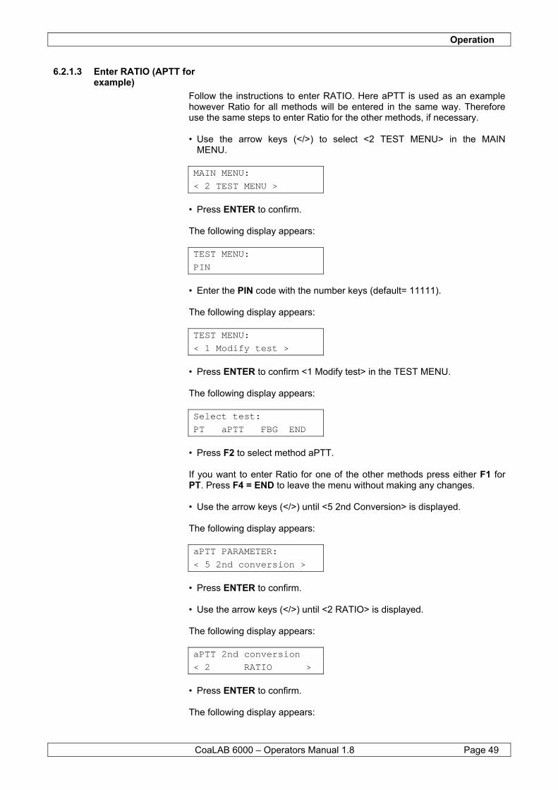
Operation
CoaLAB 6000 – Operators Manual 1.8 Page 49
6.2.1.3 Enter RATIO (APTT for example)
Follow the instructions to enter RATIO. Here aPTT is used as an example however Ratio for all methods will be entered in the same way. Therefore use the same steps to enter Ratio for the other methods, if necessary. • Use the arrow keys (</>) to select <2 TEST MENU> in the MAIN MENU. MAIN MENU:
< 2 TEST MENU >
• Press ENTER to confirm. The following display appears: TEST MENU:
PIN
• Enter the PIN code with the number keys (default= 11111). The following display appears: TEST MENU:
< 1 Modify test >
• Press ENTER to confirm <1 Modify test> in the TEST MENU. The following display appears: Select test:
PT aPTT FBG END
• Press F2 to select method aPTT. If you want to enter Ratio for one of the other methods press either F1 for PT. Press F4 = END to leave the menu without making any changes. • Use the arrow keys (</>) until <5 2nd Conversion> is displayed. The following display appears: aPTT PARAMETER:
< 5 2nd conversion >
• Press ENTER to confirm. • Use the arrow keys (</>) until <2 RATIO> is displayed. The following display appears: aPTT 2nd conversion
< 2 RATIO >
• Press ENTER to confirm. The following display appears:
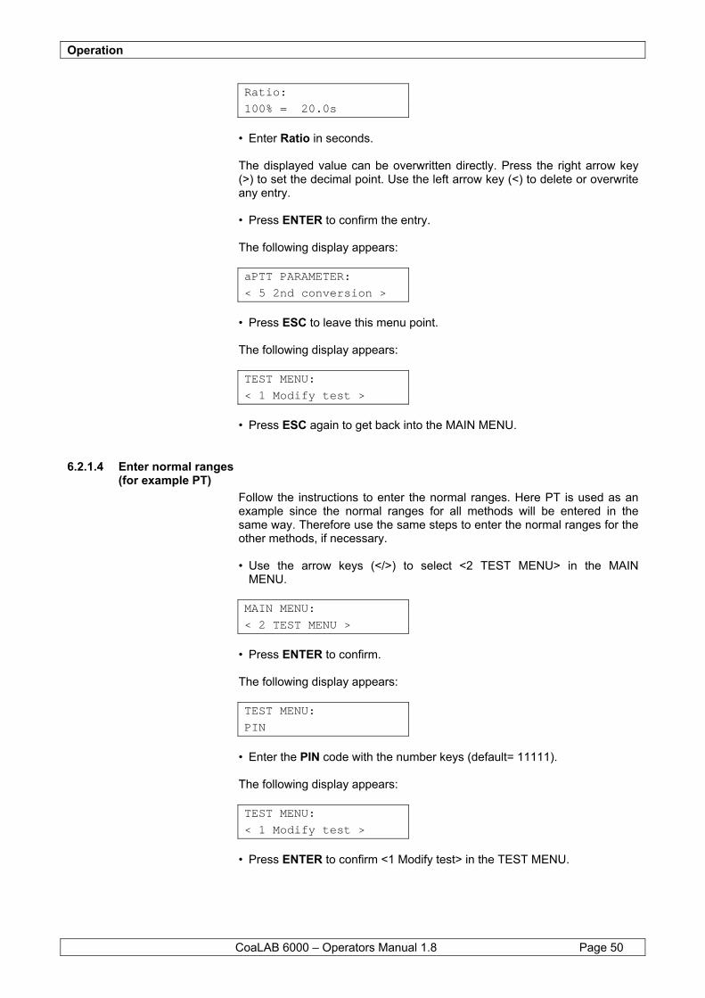
Operation
CoaLAB 6000 – Operators Manual 1.8 Page 50
Ratio:
100% = 20.0s
• Enter Ratio in seconds. The displayed value can be overwritten directly. Press the right arrow key (>) to set the decimal point. Use the left arrow key (<) to delete or overwrite any entry. • Press ENTER to confirm the entry. The following display appears: aPTT PARAMETER:
< 5 2nd conversion >
• Press ESC to leave this menu point. The following display appears: TEST MENU:
< 1 Modify test >
• Press ESC again to get back into the MAIN MENU.
6.2.1.4 Enter normal ranges (for example PT)
Follow the instructions to enter the normal ranges. Here PT is used as an example since the normal ranges for all methods will be entered in the same way. Therefore use the same steps to enter the normal ranges for the other methods, if necessary. • Use the arrow keys (</>) to select <2 TEST MENU> in the MAIN MENU. MAIN MENU:
< 2 TEST MENU >
• Press ENTER to confirm. The following display appears: TEST MENU:
PIN
• Enter the PIN code with the number keys (default= 11111). The following display appears: TEST MENU:
< 1 Modify test >
• Press ENTER to confirm <1 Modify test> in the TEST MENU.
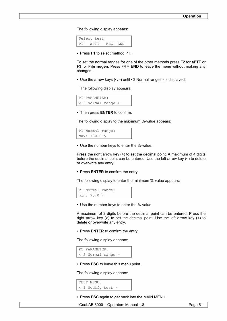
Operation
CoaLAB 6000 – Operators Manual 1.8 Page 51
The following display appears: Select test:
PT aPTT FBG END
• Press F1 to select method PT. To set the normal ranges for one of the other methods press F2 for aPTT or F3 for Fibrinogen. Press F4 = END to leave the menu without making any changes. • Use the arrow keys (</>) until <3 Normal ranges> is displayed. The following display appears: PT PARAMETER:
< 3 Normal range >
• Then press ENTER to confirm. The following display to the maximum %-value appears: PT Normal range:
max: 130.0 %
• Use the number keys to enter the %-value. Press the right arrow key (>) to set the decimal point. A maximum of 4 digits before the decimal point can be entered. Use the left arrow key (<) to delete or overwrite any entry. • Press ENTER to confirm the entry. The following display to enter the minimum %-value appears: PT Normal range:
min: 70.0 %
• Use the number keys to enter the %-value A maximum of 2 digits before the decimal point can be entered. Press the right arrow key (>) to set the decimal point. Use the left arrow key (<) to delete or overwrite any entry. • Press ENTER to confirm the entry. The following display appears: PT PARAMETER:
< 3 Normal range >
• Press ESC to leave this menu point. The following display appears:
TEST MENU:
< 1 Modify test >
• Press ESC again to get back into the MAIN MENU.
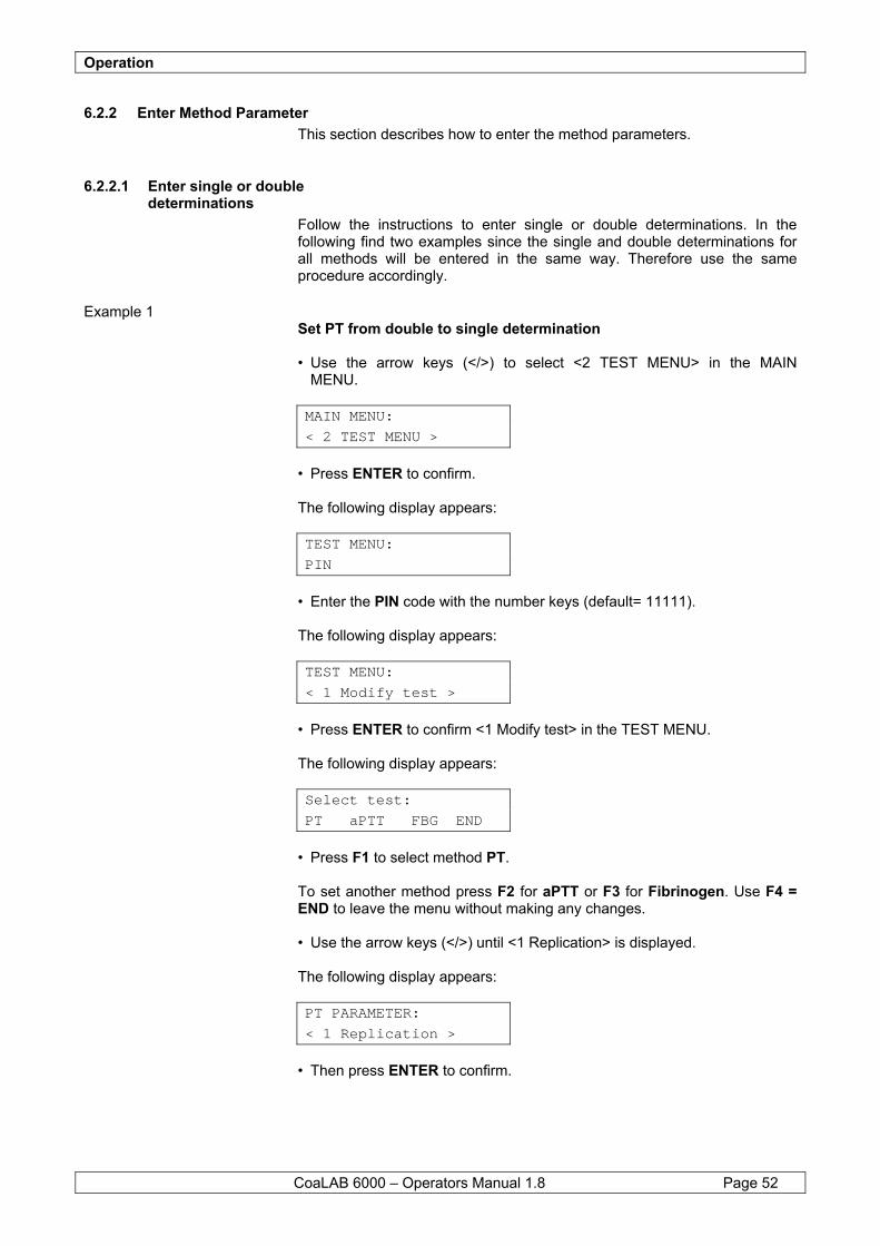
Operation
CoaLAB 6000 – Operators Manual 1.8 Page 52
6.2.2 Enter Method Parameter This section describes how to enter the method parameters.
6.2.2.1 Enter single or double determinations
Follow the instructions to enter single or double determinations. In the following find two examples since the single and double determinations for all methods will be entered in the same way. Therefore use the same procedure accordingly.
Example 1 Set PT from double to single determination • Use the arrow keys (</>) to select <2 TEST MENU> in the MAIN MENU. MAIN MENU:
< 2 TEST MENU >
• Press ENTER to confirm. The following display appears: TEST MENU:
PIN
• Enter the PIN code with the number keys (default= 11111). The following display appears: TEST MENU:
< 1 Modify test >
• Press ENTER to confirm <1 Modify test> in the TEST MENU. The following display appears: Select test:
PT aPTT FBG END
• Press F1 to select method PT. To set another method press F2 for aPTT or F3 for Fibrinogen. Use F4 = END to leave the menu without making any changes. • Use the arrow keys (</>) until <1 Replication> is displayed. The following display appears: PT PARAMETER:
< 1 Replication >
• Then press ENTER to confirm.
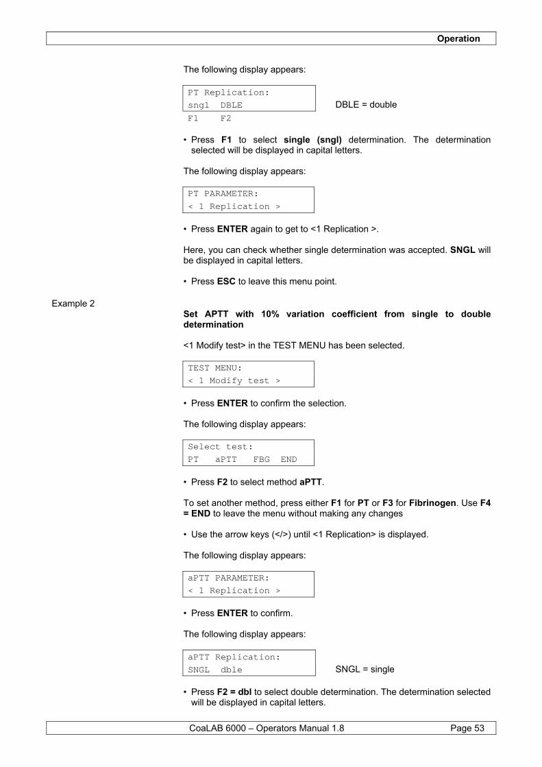
Operation
CoaLAB 6000 – Operators Manual 1.8 Page 53
The following display appears:
PT Replication: sngl DBLE DBLE = double F1 F2
• Press F1 to select single (sngl) determination. The determination
selected will be displayed in capital letters. The following display appears: PT PARAMETER:
< 1 Replication >
• Press ENTER again to get to <1 Replication >. Here, you can check whether single determination was accepted. SNGL will be displayed in capital letters. • Press ESC to leave this menu point.
Example 2 Set APTT with 10% variation coefficient from single to double determination <1 Modify test> in the TEST MENU has been selected. TEST MENU:
< 1 Modify test >
• Press ENTER to confirm the selection. The following display appears: Select test:
PT aPTT FBG END
• Press F2 to select method aPTT. To set another method, press either F1 for PT or F3 for Fibrinogen. Use F4 = END to leave the menu without making any changes • Use the arrow keys (</>) until <1 Replication> is displayed. The following display appears: aPTT PARAMETER:
< 1 Replication >
• Press ENTER to confirm. The following display appears:
aPTT Replication: SNGL dble SNGL = single
• Press F2 = dbl to select double determination. The determination selected
will be displayed in capital letters.
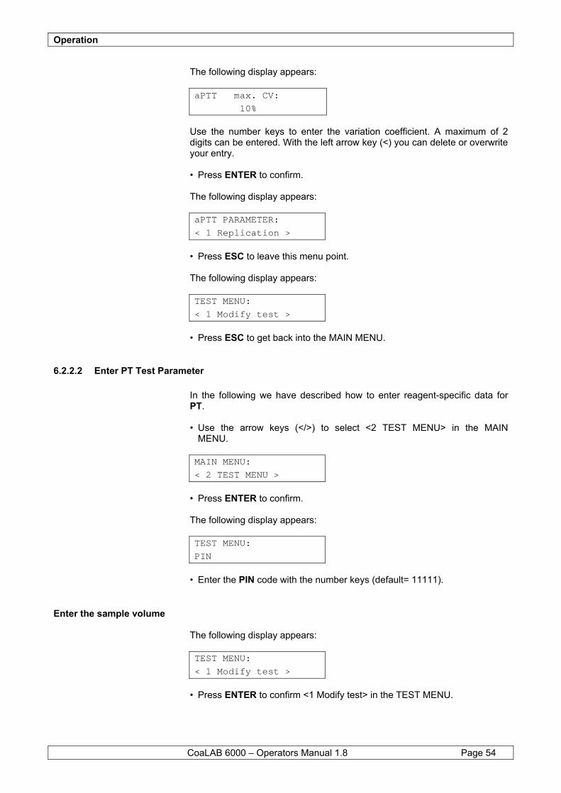
Operation
CoaLAB 6000 – Operators Manual 1.8 Page 54
The following display appears:
aPTT max. CV: 10%
Use the number keys to enter the variation coefficient. A maximum of 2 digits can be entered. With the left arrow key (<) you can delete or overwrite your entry. • Press ENTER to confirm. The following display appears: aPTT PARAMETER:
< 1 Replication >
• Press ESC to leave this menu point. The following display appears: TEST MENU:
< 1 Modify test >
• Press ESC to get back into the MAIN MENU.
6.2.2.2 Enter PT Test Parameter In the following we have described how to enter reagent-specific data for PT. • Use the arrow keys (</>) to select <2 TEST MENU> in the MAIN MENU. MAIN MENU:
< 2 TEST MENU >
• Press ENTER to confirm. The following display appears: TEST MENU:
PIN
• Enter the PIN code with the number keys (default= 11111).
Enter the sample volume The following display appears: TEST MENU:
< 1 Modify test >
• Press ENTER to confirm <1 Modify test> in the TEST MENU.
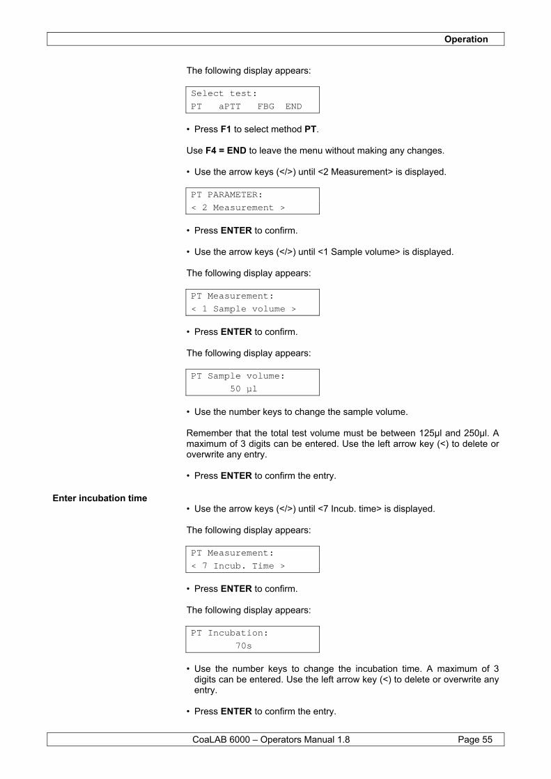
Operation
CoaLAB 6000 – Operators Manual 1.8 Page 55
The following display appears: Select test:
PT aPTT FBG END
• Press F1 to select method PT. Use F4 = END to leave the menu without making any changes. • Use the arrow keys (</>) until <2 Measurement> is displayed. PT PARAMETER:
< 2 Measurement >
• Press ENTER to confirm. • Use the arrow keys (</>) until <1 Sample volume> is displayed. The following display appears: PT Measurement:
< 1 Sample volume >
• Press ENTER to confirm. The following display appears: PT Sample volume:
50 µl
• Use the number keys to change the sample volume. Remember that the total test volume must be between 125µl and 250µl. A maximum of 3 digits can be entered. Use the left arrow key (<) to delete or overwrite any entry. • Press ENTER to confirm the entry.
Enter incubation time • Use the arrow keys (</>) until <7 Incub. time> is displayed. The following display appears: PT Measurement:
< 7 Incub. Time >
• Press ENTER to confirm. The following display appears: PT Incubation:
70s
• Use the number keys to change the incubation time. A maximum of 3
digits can be entered. Use the left arrow key (<) to delete or overwrite any entry.
• Press ENTER to confirm the entry.
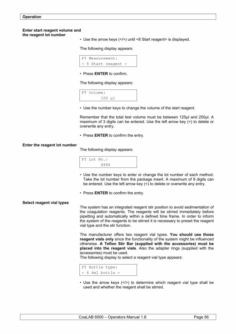
Operation
CoaLAB 6000 – Operators Manual 1.8 Page 56
Enter start reagent volume and the reagent lot number
• Use the arrow keys (</>) until <8 Start reagent> is displayed. The following display appears: PT Measurement:
< 8 Start reagent >
• Press ENTER to confirm. The following display appears: PT volume:
100 µl
• Use the number keys to change the volume of the start reagent. Remember that the total test volume must be between 125µl and 250µl. A maximum of 3 digits can be entered. Use the left arrow key (<) to delete or overwrite any entry. • Press ENTER to confirm the entry.
Enter the reagent lot number The following display appears: PT Lot No.:
8888
• Use the number keys to enter or change the lot number of each method.
Take the lot number from the package insert. A maximum of 9 digits can be entered. Use the left arrow key (<) to delete or overwrite any entry.
• Press ENTER to confirm the entry.
Select reagent vial types The system has an integrated reagent stir position to avoid sedimentation of the coagulation reagents. The reagents will be stirred immediately before pipetting and automatically within a defined time frame. In order to inform the system of the reagents to be stirred it is necessary to preset the reagent vial type and the stir function. The manufacturer offers two reagent vial types. You should use those reagent vials only since the functionality of the system might be influenced otherwise. A Teflon Stir Bar (supplied with the accessories) must be placed into the reagent vials. Also the adapter rings (supplied with the accessories) must be used. The following display to select a reagent vial type appears: PT Bottle type:
< 6 4ml bottle >
• Use the arrow keys (</>) to determine which reagent vial type shall be
used and whether the reagent shall be stirred.
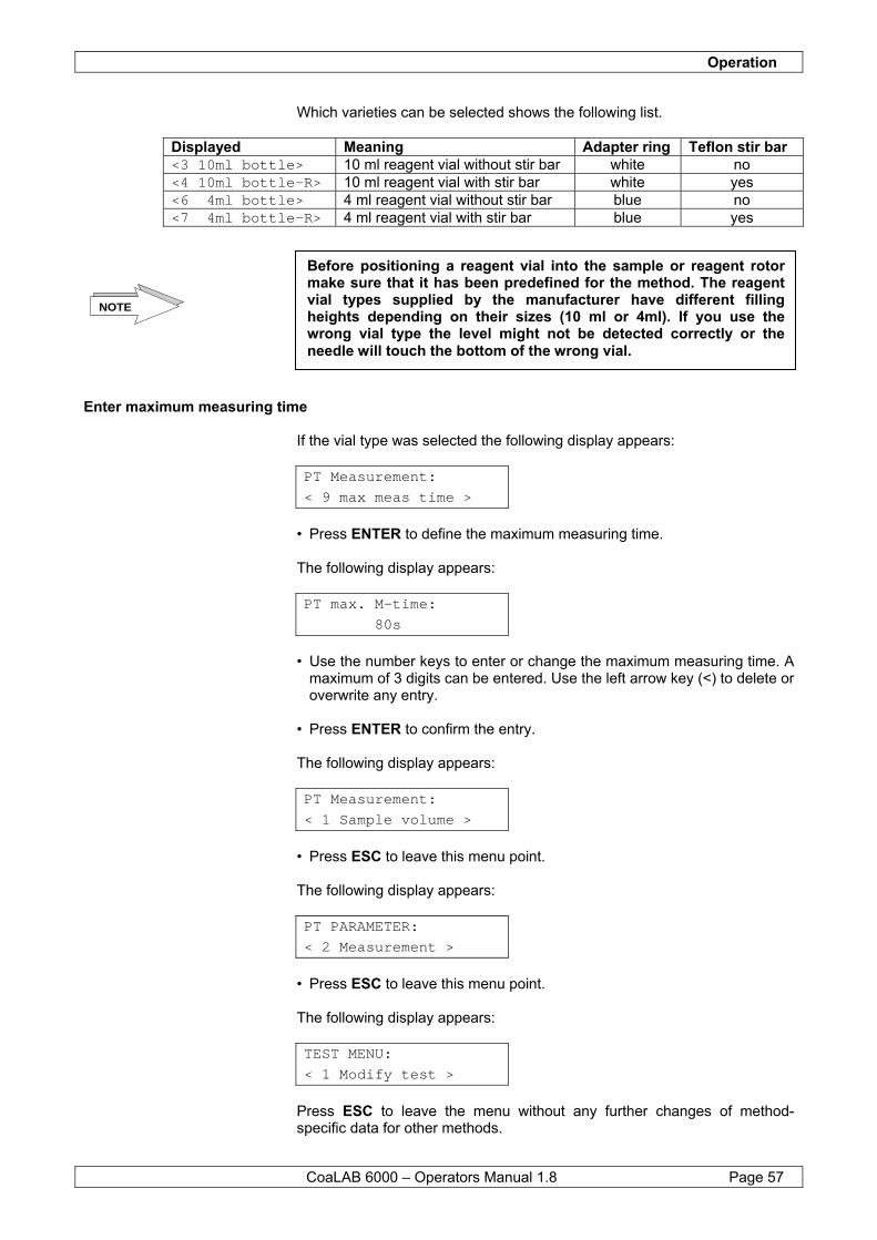
Operation
CoaLAB 6000 – Operators Manual 1.8 Page 57
Which varieties can be selected shows the following list.
Displayed Meaning Adapter ring Teflon stir bar <3 10ml bottle> 10 ml reagent vial without stir bar white no <4 10ml bottle-R> 10 ml reagent vial with stir bar white yes <6 4ml bottle> 4 ml reagent vial without stir bar blue no <7 4ml bottle-R> 4 ml reagent vial with stir bar blue yes
Enter maximum measuring time If the vial type was selected the following display appears: PT Measurement:
< 9 max meas time >
• Press ENTER to define the maximum measuring time. The following display appears: PT max. M-time:
80s
• Use the number keys to enter or change the maximum measuring time. A
maximum of 3 digits can be entered. Use the left arrow key (<) to delete or overwrite any entry.
• Press ENTER to confirm the entry. The following display appears: PT Measurement:
< 1 Sample volume >
• Press ESC to leave this menu point. The following display appears: PT PARAMETER:
< 2 Measurement >
• Press ESC to leave this menu point. The following display appears: TEST MENU:
< 1 Modify test >
Press ESC to leave the menu without any further changes of method-specific data for other methods.
Before positioning a reagent vial into the sample or reagent rotor make sure that it has been predefined for the method. The reagent vial types supplied by the manufacturer have different filling heights depending on their sizes (10 ml or 4ml). If you use the wrong vial type the level might not be detected correctly or the needle will touch the bottom of the wrong vial.
NOTE
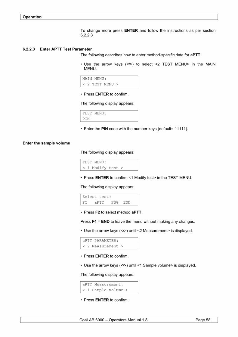
Operation
CoaLAB 6000 – Operators Manual 1.8 Page 58
To change more press ENTER and follow the instructions as per section 6.2.2.3
6.2.2.3 Enter APTT Test Parameter The following describes how to enter method-specific data for aPTT. • Use the arrow keys (</>) to select <2 TEST MENU> in the MAIN MENU. MAIN MENU:
< 2 TEST MENU >
• Press ENTER to confirm. The following display appears: TEST MENU:
PIN
• Enter the PIN code with the number keys (default= 11111).
Enter the sample volume The following display appears: TEST MENU:
< 1 Modify test >
• Press ENTER to confirm <1 Modify test> in the TEST MENU. The following display appears: Select test:
PT aPTT FBG END
• Press F2 to select method aPTT. Press F4 = END to leave the menu without making any changes.
• Use the arrow keys (</>) until <2 Measurement> is displayed. aPTT PARAMETER:
< 2 Measurement >
• Press ENTER to confirm. • Use the arrow keys (</>) until <1 Sample volume> is displayed. The following display appears: aPTT Measurement:
< 1 Sample volume >
• Press ENTER to confirm.
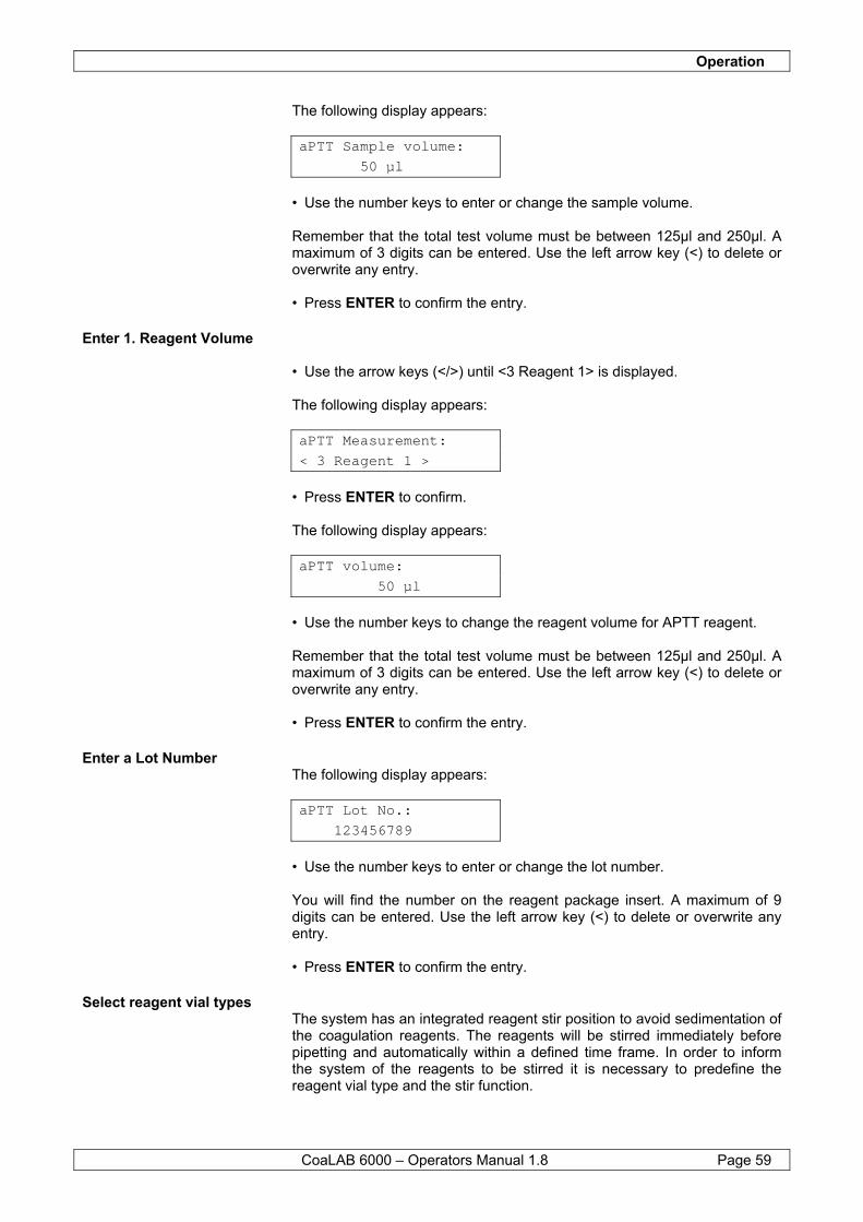
Operation
CoaLAB 6000 – Operators Manual 1.8 Page 59
The following display appears: aPTT Sample volume:
50 µl
• Use the number keys to enter or change the sample volume. Remember that the total test volume must be between 125µl and 250µl. A maximum of 3 digits can be entered. Use the left arrow key (<) to delete or overwrite any entry. • Press ENTER to confirm the entry.
Enter 1. Reagent Volume • Use the arrow keys (</>) until <3 Reagent 1> is displayed. The following display appears: aPTT Measurement:
< 3 Reagent 1 >
• Press ENTER to confirm. The following display appears: aPTT volume:
50 µl
• Use the number keys to change the reagent volume for APTT reagent. Remember that the total test volume must be between 125µl and 250µl. A maximum of 3 digits can be entered. Use the left arrow key (<) to delete or overwrite any entry. • Press ENTER to confirm the entry.
Enter a Lot Number The following display appears: aPTT Lot No.:
123456789
• Use the number keys to enter or change the lot number. You will find the number on the reagent package insert. A maximum of 9 digits can be entered. Use the left arrow key (<) to delete or overwrite any entry. • Press ENTER to confirm the entry.
Select reagent vial types The system has an integrated reagent stir position to avoid sedimentation of the coagulation reagents. The reagents will be stirred immediately before pipetting and automatically within a defined time frame. In order to inform the system of the reagents to be stirred it is necessary to predefine the reagent vial type and the stir function.
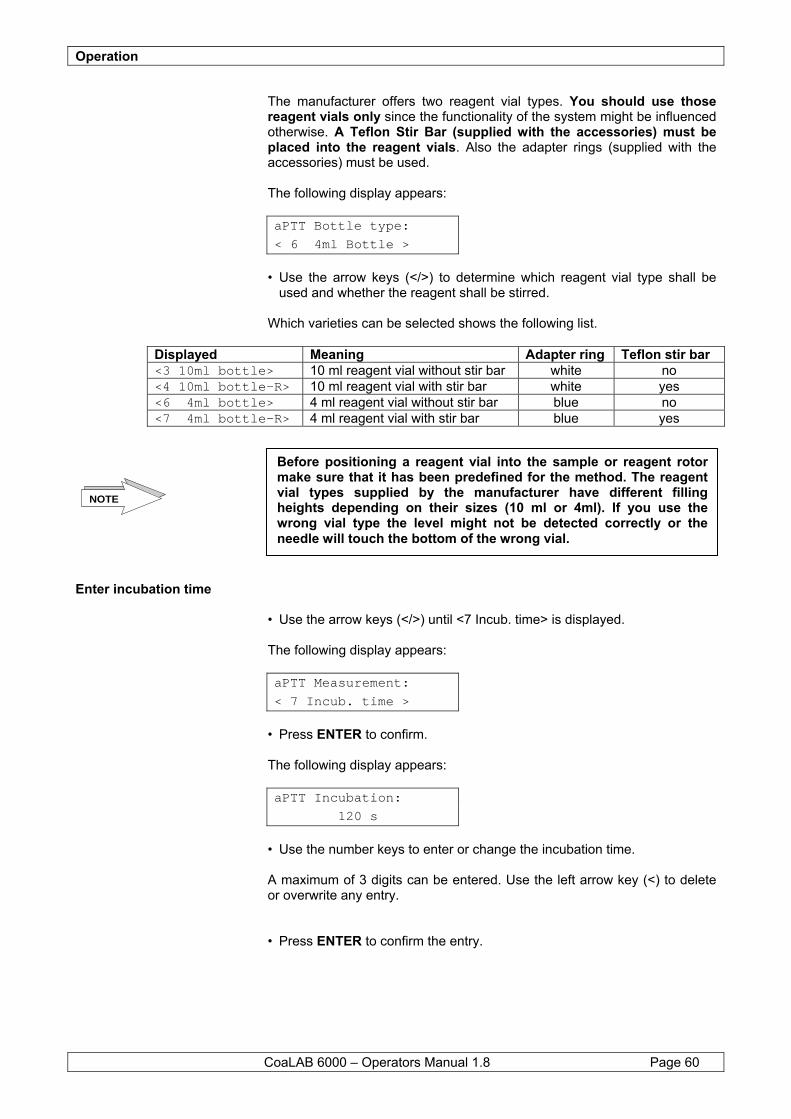
Operation
CoaLAB 6000 – Operators Manual 1.8 Page 60
The manufacturer offers two reagent vial types. You should use those reagent vials only since the functionality of the system might be influenced otherwise. A Teflon Stir Bar (supplied with the accessories) must be placed into the reagent vials. Also the adapter rings (supplied with the accessories) must be used.
The following display appears: aPTT Bottle type:
< 6 4ml Bottle >
• Use the arrow keys (</>) to determine which reagent vial type shall be
used and whether the reagent shall be stirred. Which varieties can be selected shows the following list.
Displayed Meaning Adapter ring Teflon stir bar <3 10ml bottle> 10 ml reagent vial without stir bar white no <4 10ml bottle-R> 10 ml reagent vial with stir bar white yes <6 4ml bottle> 4 ml reagent vial without stir bar blue no <7 4ml bottle-R> 4 ml reagent vial with stir bar blue yes
Enter incubation time • Use the arrow keys (</>) until <7 Incub. time> is displayed. The following display appears: aPTT Measurement:
< 7 Incub. time >
• Press ENTER to confirm. The following display appears: aPTT Incubation:
120 s
• Use the number keys to enter or change the incubation time. A maximum of 3 digits can be entered. Use the left arrow key (<) to delete or overwrite any entry. • Press ENTER to confirm the entry.
Before positioning a reagent vial into the sample or reagent rotor make sure that it has been predefined for the method. The reagent vial types supplied by the manufacturer have different filling heights depending on their sizes (10 ml or 4ml). If you use the wrong vial type the level might not be detected correctly or the needle will touch the bottom of the wrong vial.
NOTE
Operation
CoaLAB 6000 – Operators Manual 1.8 Page 61
Enter Start Reagent Volume • Use the arrow keys (</>) until <8 Start reagent> is displayed. The following display appears: aPTT Measurement:
< 8 Start reagent >
• Press ENTER to confirm. The following display appears: CaCl2 volume:
50 µl
• Use the number keys to enter or change the reagent volume for Calcium
Chloride. Remember that the total test volume must be between 125µl and 250µl. A maximum of 3 digits can be entered. Use the left arrow key (<) to delete or overwrite any entry. • Press ENTER to confirm the entry.
Enter a Lot Number The following display appears: CaCl2 Lot No.:
123456789
• Use the number keys to enter or change the lot number. The number is on the reagent package insert. A maximum of 9 digits can be entered. Use the left arrow key (<) to delete or overwrite any entry. • Press ENTER to confirm the entry.
Select Reagent Vial Types Select the reagent vial type for calcium chloride and decide whether the reagent shall be stirred. To change the setting for the reagent vial type follow the instructions above. The following display appears: CaCl2 Bottle type:
< 6 4ml Bottle >
• Use the arrow keys (</>) to determine which reagent vial type shall be
used and whether the reagent shall be stirred. Which varieties can be selected shows the following list.
Displayed Meaning Adapter ring Teflon stir bar <3 10ml bottle> 10 ml reagent vial without stir bar white no <4 10ml bottle-R> 10 ml reagent vial with stir bar white yes <6 4ml bottle> 4 ml reagent vial without stir bar blue no <7 4ml bottle-R> 4 ml reagent vial with stir bar blue yes
Operation
CoaLAB 6000 – Operators Manual 1.8 Page 62
Enter Maximum Measuring Time The following display appears: aPTT Measurement:
< 9 max meas time >
• Press ENTER to confirm the maximum measuring time. The following display appears: aPTT max M-time:
120 s
• Use the number keys to enter or change the maximum measuring time. A maximum of 3 digits can be entered. Use the left arrow key (<) to delete or overwrite any entry. • Press ENTER to confirm the entry. The following display appears: aPTT Measurement:
< 1 Sample volume >
• Press ESC to leave this menu point. The following display appears: aPTT PARAMETER:
< 2 Measurement >
• Press ESC to leave this menu point. The following display appears: TEST MENU:
< 1 Modify test >
Press ESC if no further change of method-specific data for other methods is requested. To change more parameters press ENTER and follow the instructions as per section 6.2.2.4
Before positioning a reagent vial into the sample or reagent rotor make sure that it has been predefined for the method. The reagent vial types supplied by the manufacturer have different filling heights depending on their sizes (10 ml or 4ml). If you use the wrong vial type the level might not be detected correctly or the needle will touch the bottom of the wrong vial.
NOTE
Operation
CoaLAB 6000 – Operators Manual 1.8 Page 63
6.2.2.4 Enter Fibrinogen Test Parameter Follow the instructions to enter test-specific parameters. • Use the arrow keys (</>) to select <2 TEST MENU> in the MAIN MENU. MAIN MENU:
< 2 TEST MENU >
• Press ENTER to confirm. The following display appears: TEST MENU:
PIN
• Enter the PIN code with the number keys (default= 11111). The following display appears: TEST MENU:
< 1 Modify test >
• Press ENTER to confirm <1 Modify test> in the TEST MENU. The following display appears: Select test:
PT aPTT FBG END
• Select method FBG by pressing the function key F3. Press F4 = End to leave this menu without making any changes. • Use the arrow keys (</>) until <2 Measurement> is displayed. The following display appears: FBG PARAMETER:
< 2 Measurement >
• Press ENTER to confirm.
Enter the Sample Volume • Use the arrow keys (</>) until <1 Sample volume> is displayed. The following display appears: FBG Measurement:
< 1 Sample volume >
• Press ENTER to confirm. The following display appears: FBG Sample volume:
100 µl
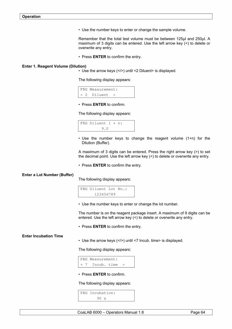
Operation
CoaLAB 6000 – Operators Manual 1.8 Page 64
• Use the number keys to enter or change the sample volume. Remember that the total test volume must be between 125µl and 250µl. A maximum of 3 digits can be entered. Use the left arrow key (<) to delete or overwrite any entry. • Press ENTER to confirm the entry.
Enter 1. Reagent Volume (Dilution) • Use the arrow keys (</>) until <2 Diluent> is displayed. The following display appears: FBG Measurement:
< 2 Diluent >
• Press ENTER to confirm. The following display appears: FBG Diluent 1 + n:
9.0
• Use the number keys to change the reagent volume (1+n) for the Dilution (Buffer). A maximum of 3 digits can be entered. Press the right arrow key (>) to set the decimal point. Use the left arrow key (<) to delete or overwrite any entry. • Press ENTER to confirm the entry.
Enter a Lot Number (Buffer) The following display appears: FBG Diluent Lot No.:
123456789
• Use the number keys to enter or change the lot number. The number is on the reagent package insert. A maximum of 9 digits can be entered. Use the left arrow key (<) to delete or overwrite any entry. • Press ENTER to confirm the entry.
Enter Incubation Time • Use the arrow keys (</>) until <7 Incub. time> is displayed. The following display appears: FBG Measurement:
< 7 Incub. time >
• Press ENTER to confirm. The following display appears: FBG Incubation:
90 s
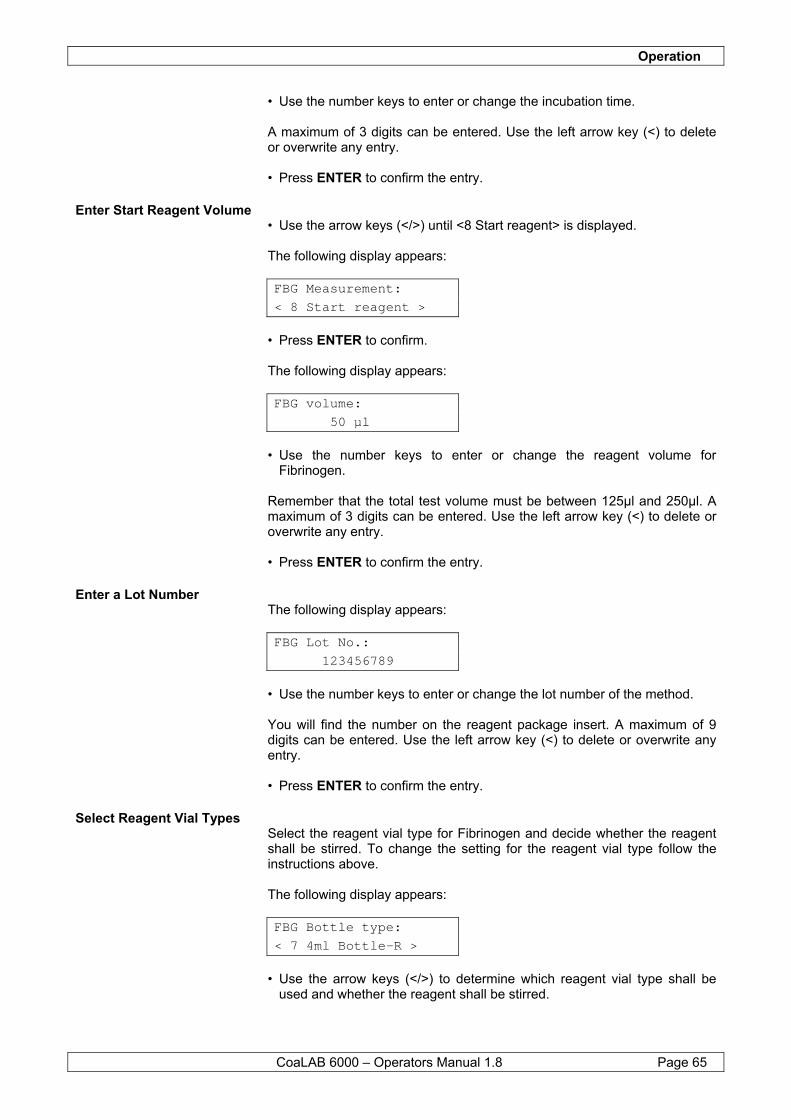
Operation
CoaLAB 6000 – Operators Manual 1.8 Page 65
• Use the number keys to enter or change the incubation time. A maximum of 3 digits can be entered. Use the left arrow key (<) to delete or overwrite any entry. • Press ENTER to confirm the entry.
Enter Start Reagent Volume • Use the arrow keys (</>) until <8 Start reagent> is displayed. The following display appears: FBG Measurement:
< 8 Start reagent >
• Press ENTER to confirm. The following display appears: FBG volume:
50 µl
• Use the number keys to enter or change the reagent volume for
Fibrinogen. Remember that the total test volume must be between 125µl and 250µl. A maximum of 3 digits can be entered. Use the left arrow key (<) to delete or overwrite any entry. • Press ENTER to confirm the entry.
Enter a Lot Number The following display appears: FBG Lot No.:
123456789
• Use the number keys to enter or change the lot number of the method. You will find the number on the reagent package insert. A maximum of 9 digits can be entered. Use the left arrow key (<) to delete or overwrite any entry. • Press ENTER to confirm the entry.
Select Reagent Vial Types Select the reagent vial type for Fibrinogen and decide whether the reagent shall be stirred. To change the setting for the reagent vial type follow the instructions above. The following display appears: FBG Bottle type:
< 7 4ml Bottle-R >
• Use the arrow keys (</>) to determine which reagent vial type shall be
used and whether the reagent shall be stirred.
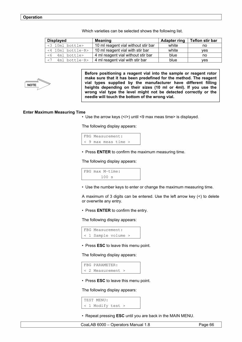
Operation
CoaLAB 6000 – Operators Manual 1.8 Page 66
Which varieties can be selected shows the following list.
Displayed Meaning Adapter ring Teflon stir bar <3 10ml bottle> 10 ml reagent vial without stir bar white no <4 10ml bottle-R> 10 ml reagent vial with stir bar white yes <6 4ml bottle> 4 ml reagent vial without stir bar blue no <7 4ml bottle-R> 4 ml reagent vial with stir bar blue yes
Enter Maximum Measuring Time • Use the arrow keys (</>) until <9 max meas time> is displayed. The following display appears: FBG Measurement:
< 9 max meas time >
• Press ENTER to confirm the maximum measuring time. The following display appears: FBG max M-time:
100 s
• Use the number keys to enter or change the maximum measuring time. A maximum of 3 digits can be entered. Use the left arrow key (<) to delete or overwrite any entry. • Press ENTER to confirm the entry. The following display appears: FBG Measurement:
< 1 Sample volume >
• Press ESC to leave this menu point. The following display appears: FBG PARAMETER:
< 2 Measurement >
• Press ESC to leave this menu point. The following display appears: TEST MENU:
< 1 Modify test >
• Repeat pressing ESC until you are back in the MAIN MENU.
Before positioning a reagent vial into the sample or reagent rotor make sure that it has been predefined for the method. The reagent vial types supplied by the manufacturer have different filling heights depending on their sizes (10 ml or 4ml). If you use the wrong vial type the level might not be detected correctly or the needle will touch the bottom of the wrong vial.
NOTE
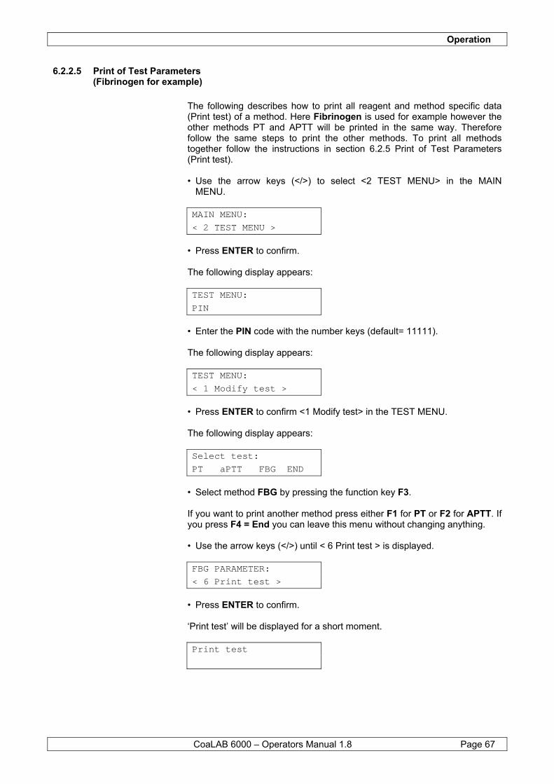
Operation
CoaLAB 6000 – Operators Manual 1.8 Page 67
6.2.2.5 Print of Test Parameters (Fibrinogen for example)
The following describes how to print all reagent and method specific data (Print test) of a method. Here Fibrinogen is used for example however the other methods PT and APTT will be printed in the same way. Therefore follow the same steps to print the other methods. To print all methods together follow the instructions in section 6.2.5 Print of Test Parameters (Print test). • Use the arrow keys (</>) to select <2 TEST MENU> in the MAIN MENU. MAIN MENU:
< 2 TEST MENU >
• Press ENTER to confirm. The following display appears: TEST MENU:
PIN
• Enter the PIN code with the number keys (default= 11111). The following display appears: TEST MENU:
< 1 Modify test >
• Press ENTER to confirm <1 Modify test> in the TEST MENU. The following display appears: Select test:
PT aPTT FBG END
• Select method FBG by pressing the function key F3. If you want to print another method press either F1 for PT or F2 for APTT. If you press F4 = End you can leave this menu without changing anything. • Use the arrow keys (</>) until < 6 Print test > is displayed. FBG PARAMETER:
< 6 Print test >
• Press ENTER to confirm. ‘Print test’ will be displayed for a short moment. Print test
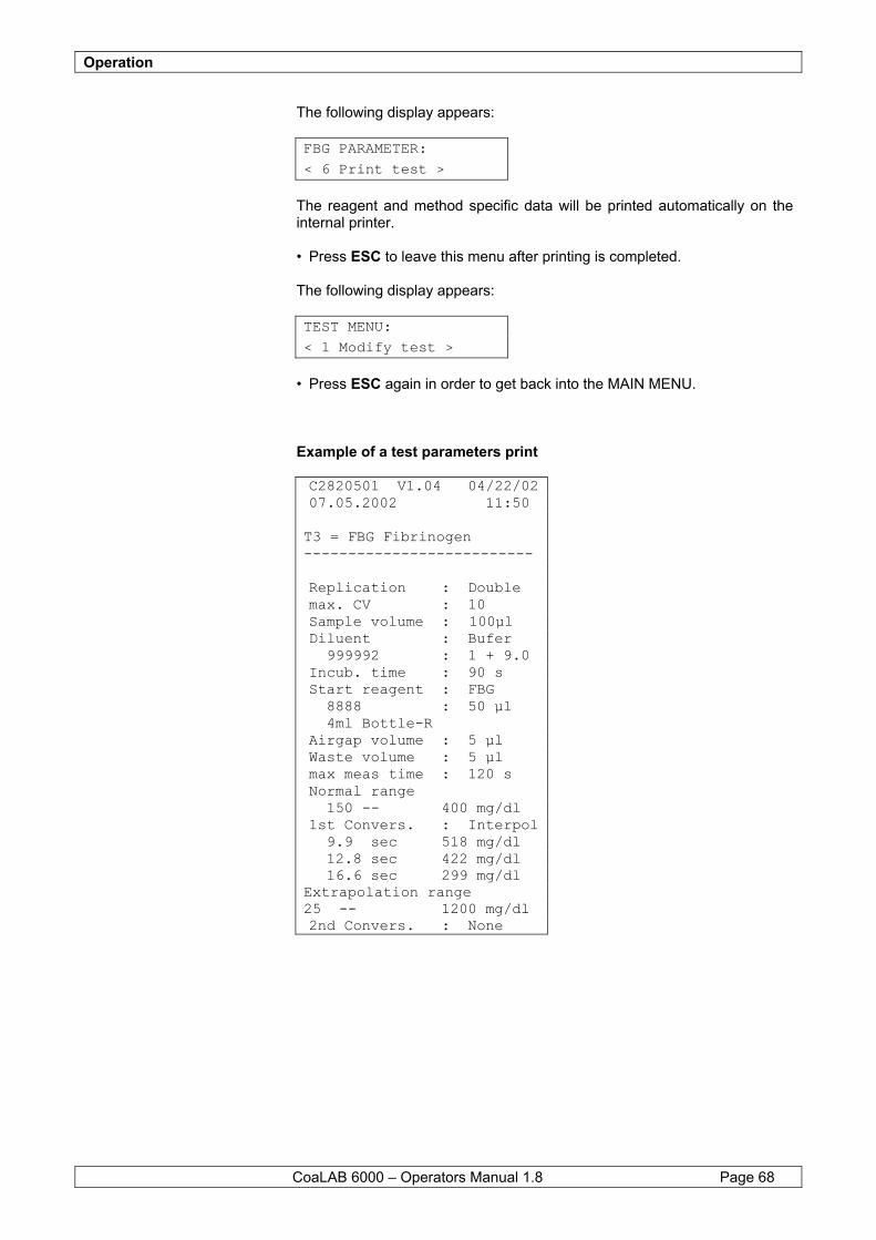
Operation
CoaLAB 6000 – Operators Manual 1.8 Page 68
The following display appears: FBG PARAMETER:
< 6 Print test >
The reagent and method specific data will be printed automatically on the internal printer. • Press ESC to leave this menu after printing is completed. The following display appears: TEST MENU:
< 1 Modify test >
• Press ESC again in order to get back into the MAIN MENU. Example of a test parameters print C2820501 V1.04 04/22/02 07.05.2002 11:50 T3 = FBG Fibrinogen -------------------------- Replication : Double max. CV : 10 Sample volume : 100µl Diluent : Bufer 999992 : 1 + 9.0 Incub. time : 90 s Start reagent : FBG 8888 : 50 µl 4ml Bottle-R Airgap volume : 5 µl Waste volume : 5 µl max meas time : 120 s Normal range 150 -- 400 mg/dl 1st Convers. : Interpol 9.9 sec 518 mg/dl 12.8 sec 422 mg/dl 16.6 sec 299 mg/dl Extrapolation range 25 -- 1200 mg/dl 2nd Convers. : None
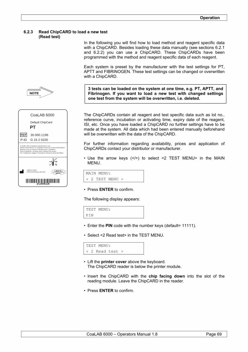
Operation
CoaLAB 6000 – Operators Manual 1.8 Page 69
6.2.3 Read ChipCARD to load a new test (Read test)
In the following you will find how to load method and reagent specific data with a ChipCARD. Besides loading these data manually (see sections 6.2.1 and 6.2.2) you can use a ChipCARD. These ChipCARDs have been programmed with the method and reagent specific data of each reagent. Each system is preset by the manufacturer with the test settings for PT, APTT and FIBRINOGEN. These test settings can be changed or overwritten with a ChipCARD.
The ChipCARDs contain all reagent and test specific data such as lot no., reference curve, incubation or activating time, expiry date of the reagent, ISI, etc. Once you have loaded a ChipCARD no further settings have to be made at the system. All data which had been entered manually beforehand will be overwritten with the data of the ChipCARD. For further information regarding availability, prices and application of ChipCARDs contact your distributor or manufacturer. • Use the arrow keys (</>) to select <2 TEST MENU> in the MAIN MENU. MAIN MENU:
< 2 TEST MENU >
• Press ENTER to confirm. The following display appears: TEST MENU:
PIN
• Enter the PIN code with the number keys (default= 11111). • Select <2 Read test> in the TEST MENU. TEST MENU:
< 2 Read test >
• Lift the printer cover above the keyboard. The ChipCARD reader is below the printer module. • Insert the ChipCARD with the chip facing down into the slot of the
reading module. Leave the ChipCARD in the reader. • Press ENTER to confirm.
NOTE3 tests can be loaded on the system at one time, e.g. PT, APTT, and Fibrinogen. If you want to load a new test with changed settings one test from the system will be overwritten, i.e. deleted.
P-ID G 15 2 0220
PTDefault ChipCard
To install, refer to operators manual prior to use.Weitere Informationen zur Installation finden Sie im Benutzerhandbuch.Reportez-vous au manuel d´utilisation pour l´installation.Para la instalación, consultar antes el Manuel del usuario.Per l´installazione, leggere Il manuale di instruzioni prima dell´utillizo.
30.000.1196
LABiTec GmbH22926 Ahrensburg, Germany
CoaLAB 6000
_______________________
_______________________

Operation
CoaLAB 6000 – Operators Manual 1.8 Page 70
Figure 15 How to load a ChipCARD The following display appears: Overwrite test: PT aPTT FBG END
• Use the function keys F1 - F3 to select the test to be overwritten by the
ChipCARD. By pressing F4 = End you can leave this menu without making any change.
The following display appears: Read test
‘Read test’ will be displayed for a short moment. The instrument reads the ChipCARD. The following display appears: Test loaded:
Name of loaded test
A message follows that the test of the system was overwritten by the ChipCARD test. • Press ENTER to confirm. If the ChipCARD was inserted wrong or not at all the following error message will appear:
E R R O R
No CARD found
• Press ENTER to confirm this message and repeat the procedure.
Printer unit
Keypad
ChipCARD Reader
ChipCARD
Operation
CoaLAB 6000 – Operators Manual 1.8 Page 71
If you inserted a ChipCARD of which the test had been loaded already the following error message will be displayed:
E R R O R
Test already loaded
• Press ENTER to confirm this message and repeat the procedure with
another ChipCARD. Withdraw the ChipCARD from the reader and close the printer cover again. If you want to overwrite more tests of the system repeat the above steps for all new tests. The following display appears: TEST MENU:
< 2 Read test >
• Press ESC in order to get back into the MAIN MENU.
6.2.4 Save Tests on a ChipCARD
Find below how to write test parameters, including calibration curve, to a ChipCARD and how to save the data. Editable ChipCARDs can be bought from the manufacturer, see Chapter 8.5 Accessories and Consumables. It is possible to save test parameters for a specific reagent lot so that you can use this test again when a reagent of the same lot is used. No parameters have to be entered manually. Since the procedure of saving test parameters on a ChipCARD is the same for all tests we have taken the PT test as an example. • Use the arrow keys (</>) to select <2 TEST MENU> in the MAIN MENU. MAIN MENU:
< 2 TEST MENU >
• Press ENTER to confirm. The following display appears: TEST MENU:
PIN
• Enter the PIN code with the number keys (default= 11111). The following display appears: TEST MENU:
< 1 Modify test >
• Press the arrow keys (</>) until <5 Write test> is displayed. TEST MENU:
< 5 Write test >
Operation
CoaLAB 6000 – Operators Manual 1.8 Page 72
• Press ENTER to select the function. • Insert the ChipCARD into the reader. Use either a blank CARD or an
already edited ChipCARD. If you select a used ChipCARD remember that all data on the ChipCARD will be overwritten.
The following display appears:
Select test: PT aPTT FBG END F1 F2 F3 F4
• Select the test to be saved by pressing one of the function keys F1 - F3.
By pressing F4 = End you can leave this menu without making any changes.
The following display appears: Write test
‘Write test’ will be displayed while the data is written to the ChipCARD. Test written:
Name of written test
An acoustic signal will be heard at the end of saving. • Press ENTER to confirm. • Remove the edited ChipCARD and write all test relevant information on it
for proper identification. • Put the printer cover back into its position. • Press ESC to get back into a higher menu level.
Error messages If the ChipCARD has been inserted wrong or not at all the following message will appear:
E R R O R
No CARD found
• Press ENTER to confirm and repeat the procedure after the ChipCARD
has been inserted. If you used the Default CARD the following message will appear:
E R R O R
Write protected card
• Press ENTER to confirm and repeat the procedure with another
ChipCARD.
NOTE Be careful not to use and overwrite the Default ChipCARD (also supplied in the accessories).
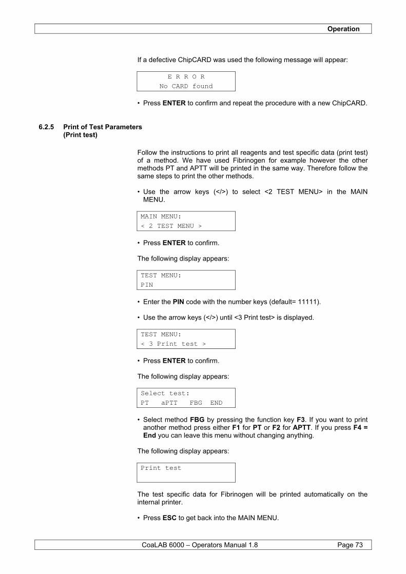
Operation
CoaLAB 6000 – Operators Manual 1.8 Page 73
If a defective ChipCARD was used the following message will appear:
E R R O R
No CARD found
• Press ENTER to confirm and repeat the procedure with a new ChipCARD.
6.2.5 Print of Test Parameters (Print test)
Follow the instructions to print all reagents and test specific data (print test) of a method. We have used Fibrinogen for example however the other methods PT and APTT will be printed in the same way. Therefore follow the same steps to print the other methods. • Use the arrow keys (</>) to select <2 TEST MENU> in the MAIN MENU. MAIN MENU:
< 2 TEST MENU >
• Press ENTER to confirm. The following display appears: TEST MENU:
PIN
• Enter the PIN code with the number keys (default= 11111). • Use the arrow keys (</>) until <3 Print test> is displayed. TEST MENU:
< 3 Print test >
• Press ENTER to confirm. The following display appears: Select test:
PT aPTT FBG END
• Select method FBG by pressing the function key F3. If you want to print
another method press either F1 for PT or F2 for APTT. If you press F4 = End you can leave this menu without changing anything.
The following display appears: Print test
The test specific data for Fibrinogen will be printed automatically on the internal printer. • Press ESC to get back into the MAIN MENU.
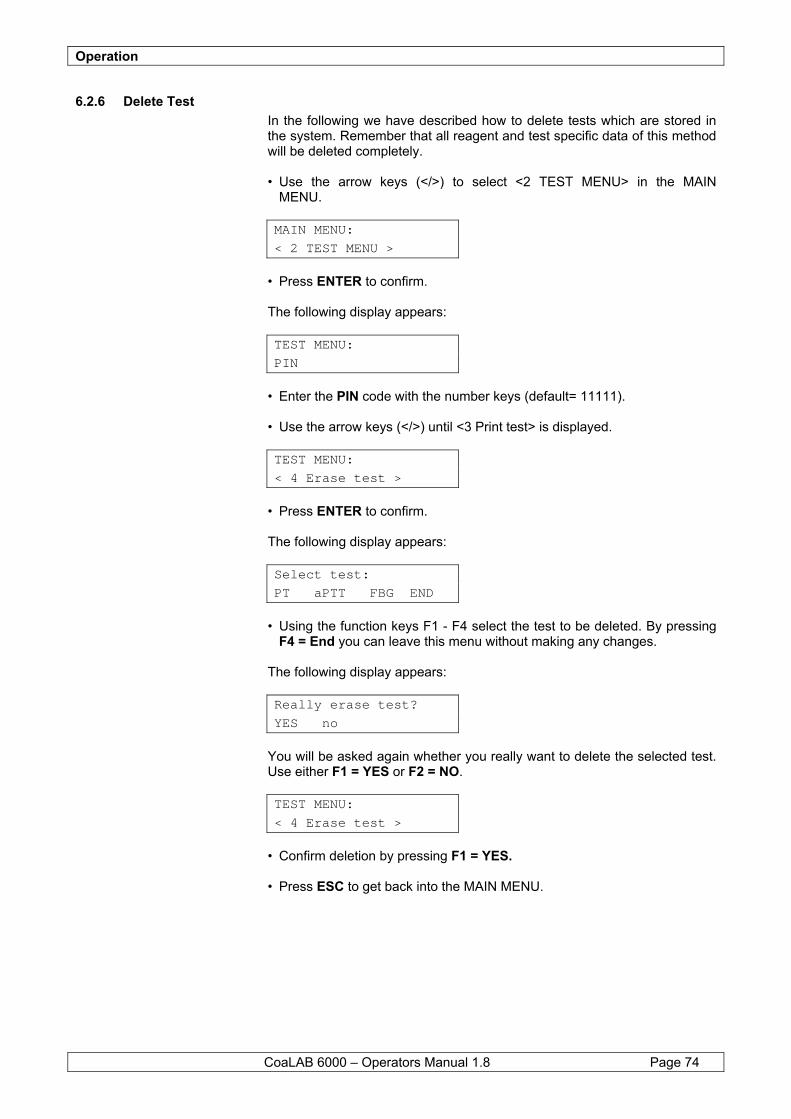
Operation
CoaLAB 6000 – Operators Manual 1.8 Page 74
6.2.6 Delete Test In the following we have described how to delete tests which are stored in the system. Remember that all reagent and test specific data of this method will be deleted completely. • Use the arrow keys (</>) to select <2 TEST MENU> in the MAIN MENU. MAIN MENU:
< 2 TEST MENU >
• Press ENTER to confirm. The following display appears: TEST MENU:
PIN
• Enter the PIN code with the number keys (default= 11111). • Use the arrow keys (</>) until <3 Print test> is displayed. TEST MENU:
< 4 Erase test >
• Press ENTER to confirm. The following display appears: Select test:
PT aPTT FBG END
• Using the function keys F1 - F4 select the test to be deleted. By pressing
F4 = End you can leave this menu without making any changes. The following display appears: Really erase test?
YES no
You will be asked again whether you really want to delete the selected test. Use either F1 = YES or F2 = NO. TEST MENU:
< 4 Erase test >
• Confirm deletion by pressing F1 = YES. • Press ESC to get back into the MAIN MENU.
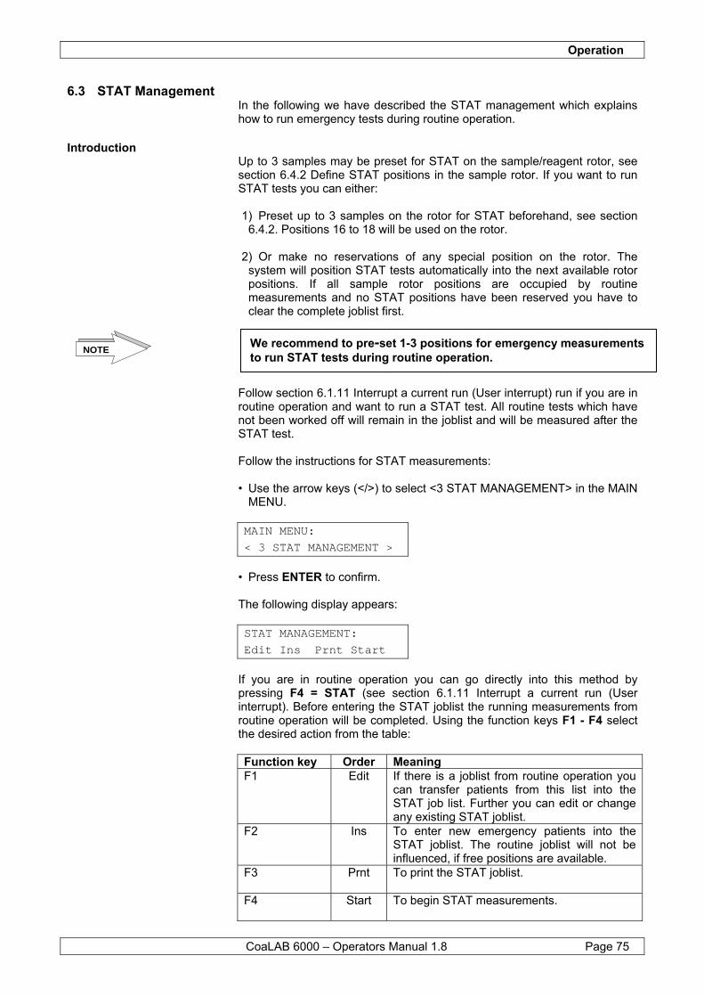
Operation
CoaLAB 6000 – Operators Manual 1.8 Page 75
6.3 STAT Management In the following we have described the STAT management which explains how to run emergency tests during routine operation.
Introduction Up to 3 samples may be preset for STAT on the sample/reagent rotor, see section 6.4.2 Define STAT positions in the sample rotor. If you want to run STAT tests you can either: 1) Preset up to 3 samples on the rotor for STAT beforehand, see section
6.4.2. Positions 16 to 18 will be used on the rotor. 2) Or make no reservations of any special position on the rotor. The
system will position STAT tests automatically into the next available rotor positions. If all sample rotor positions are occupied by routine measurements and no STAT positions have been reserved you have to clear the complete joblist first.
Follow section 6.1.11 Interrupt a current run (User interrupt) run if you are in routine operation and want to run a STAT test. All routine tests which have not been worked off will remain in the joblist and will be measured after the STAT test. Follow the instructions for STAT measurements: • Use the arrow keys (</>) to select <3 STAT MANAGEMENT> in the MAIN
MENU. MAIN MENU:
< 3 STAT MANAGEMENT >
• Press ENTER to confirm. The following display appears: STAT MANAGEMENT:
Edit Ins Prnt Start
If you are in routine operation you can go directly into this method by pressing F4 = STAT (see section 6.1.11 Interrupt a current run (User interrupt). Before entering the STAT joblist the running measurements from routine operation will be completed. Using the function keys F1 - F4 select the desired action from the table: Function key Order Meaning F1 Edit If there is a joblist from routine operation you
can transfer patients from this list into the STAT job list. Further you can edit or change any existing STAT joblist.
F2 Ins To enter new emergency patients into the STAT joblist. The routine joblist will not be influenced, if free positions are available.
F3 Prnt To print the STAT joblist.
F4 Start To begin STAT measurements.
We recommend to pre-set 1-3 positions for emergency measurements to run STAT tests during routine operation. NOTE

Operation
CoaLAB 6000 – Operators Manual 1.8 Page 76
Example F1 = Edit • Change from ROUTINE into STAT operation: • Press F1 for editing. The following display appears: 01 S-ID: 30001
pt aptt fbg all
The first patient of your ROUTINE joblist will be displayed and can be transferred into the STAT joblist. With the function keys F1-F4 you can select the methods. The selected test will be displayed in big letters. With the arrow keys up and down the next sample can be called for or skipped over. The patient samples that have been transferred from ROUTINE into the STAT joblist will be deleted in the ROUTINE list. All patient samples which have not been transferred into the STAT list will remain in the ROUTINE list for later measurements. • Press ENTER to confirm. The following display appears: STAT MANAGEMENT:
Edit Ins Prnt Start
If you want to print the STAT joblist press F3 = print. If you want to start STAT measurements press F4 = Start. For further entry of new STAT patients press F2 = Ins and follow the example below.
Example F2 = Insert Enter new patient samples into the STAT joblist: • Press F2 for inserting. The following display appears: 05 S-ID: 30005
pt aptt fbg all
The system will extend the next available sample rotor position automatically so that you can place the new primary tube. Press F1-F4 to select the methods. If you want to change the patient ID press the left arrow key (<) until the displayed ID is deleted. Now you can enter another ID with the number keys. • Press ENTER to confirm. The following display appears: 06 S-ID: 30006
pt aptt fbg all
If you want to insert further patient samples into the STAT joblist follow the steps as mentioned before. Press ESC to leave this menu.
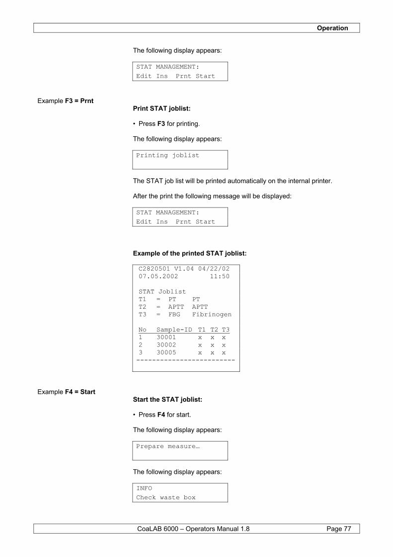
Operation
CoaLAB 6000 – Operators Manual 1.8 Page 77
The following display appears: STAT MANAGEMENT:
Edit Ins Prnt Start
Example F3 = Prnt Print STAT joblist: • Press F3 for printing. The following display appears: Printing joblist
The STAT job list will be printed automatically on the internal printer. After the print the following message will be displayed: STAT MANAGEMENT:
Edit Ins Prnt Start
Example of the printed STAT joblist: C2820501 V1.04 04/22/02 07.05.2002 11:50 STAT Joblist T1 = PT PT T2 = APTT APTT T3 = FBG Fibrinogen No Sample-ID T1 T2 T3 1 30001 x x x 2 30002 x x x 3 30005 x x x -------------------------
Example F4 = Start Start the STAT joblist: • Press F4 for start. The following display appears: Prepare measure…
The following display appears: INFO
Check waste box

Operation
CoaLAB 6000 – Operators Manual 1.8 Page 78
‘Check waste box’ will be displayed for a short moment every time a job list has been entered. If used cuvette racks are still in the waste box we recommend to empty it. The following display appears: Insert cuvette bar
and close cover
The system calculates from the joblist automatically how many cuvette racks will be needed. The sample rotor extends the next position automatically to load a cuvette rack. This procedure will be repeated until all cuvette racks necessary for the measurements have been positioned in the sample rotor. • Press ENTER to confirm. The sample rotor will extend the next available reagent position automatically. Insert the adapter ring and the reagent vial for the selected method. Remember to use predefined reagent vial types only (see Chapter 6.2.2.2). If reagents are already loaded the analyzer will check reagent volume and starts measurement automatically. Test will not function without any reagents. The necessary reagent volume will be displayed.
1: washer: LOAD 0.5ml skip
If the reagent vial is in the sample rotor you can either select F1 (load) or = the reagent has been loaded and confirmed. ENTER F4 (skip) = the reagent has not been loaded no entry confirmed
continue to next reagent. • Press F1 or ENTER in this case to confirm. The following display appears:
2: Buffer 9999992 LOAD 0.4ml skip
• The sample rotor position will be extended automatically. Load Buffer into
the sample rotor and confirm with F1. If you want to skip over this position and not load Buffer press F4. The following display appears:
3: FBG 8888 LOAD 0.3ml skip
• The sample rotor position will be extended automatically. Load Fibrinogen into the sample rotor and confirm with F1. If you want to skip over this position and not load Fibrinogen press F4.
Operation
CoaLAB 6000 – Operators Manual 1.8 Page 79
The following display appears:
4: CaCl2 12345678 LOAD 0.3ml skip
• The sample rotor position will be extended automatically. Load Calcium
Chloride into the sample rotor and confirm with F1. If you want to skip over this position and not load Calcium Chloride press
F4. The following display appears:
5: aPTT 999999995 LOAD 0.3ml skip
• The sample rotor position will be extended automatically. Load aPTT
reagent into the sample rotor and confirm with F1.
If you want to skip over this position and not load aPTT reagent press F4. The following display appears:
6: PT 123456789 LOAD 0.3ml skip
• The sample rotor position will be extended automatically. Load PT reagent
into the sample rotor and confirm with F1. If you want to skip over this position and not load PT reagent press F4. The following display appears:
Prepare measure…
After having placed the last reagent into the sample rotor of the system will check the reagents automatically. Especially the volume will be checked. If reagents are missing or the volume is insufficient the following message will be displayed:
6: PT 123456789 Only x.x of x.x ml
You can load the missing reagent now. • Press ENTER to confirm. The following display appears:
Pipettor M-Block 37.4 38.4
The message Pipettor / Tubing gives a short status on the temperature of the measuring block and the pipettor. If the temperature is not correct, i.e. 37°C or 38°C, this message will be displayed until the temperature has been reached.

Operation
CoaLAB 6000 – Operators Manual 1.8 Page 80
The following display appears:
18 Samples No Results available
The system starts measuring. The message displayed shows how many samples still have to be worked off. The results will be printed automatically on the internal printer. If results are not available yet the message ‘No results available’ will be displayed. After the measurement has been completed a beep will be heard and the following message will be displayed:
STATUS Normal Termination
Example for a result print: C2820501 V1.04 04/22/02 07.05.2002 11:50 Analyzer Mode : Batch Research Mode : Off **** STAT MANAGEMENT **** Test PT 07.05.2002 15:10 No Sample-ID Result Cuv. 1 30001 online 01ab PT time1 11.7 sec PT time2 11.7 sec PT mean 11.7 sec PT INR 1.03 PT conc 93.75 % Test aPTT 07.05.2002 15:17 No Sample-ID Result Cuv. 1 30001 online 01ef aPTT time1 35.3 sec aPTT time2 35.7 sec aPTT mean 35.5 sec aPTT Ratio 1.77 -------------------------- **END STAT MEAUREMENT**
Finished 07.05.2002 15:45 State: Normal Termination
You can interrupt the STAT measurement by pressing the ESC-key. Follow the instructions as per Chapter 6.1.11 Interrupt a current run (User interrupt).
NOTE
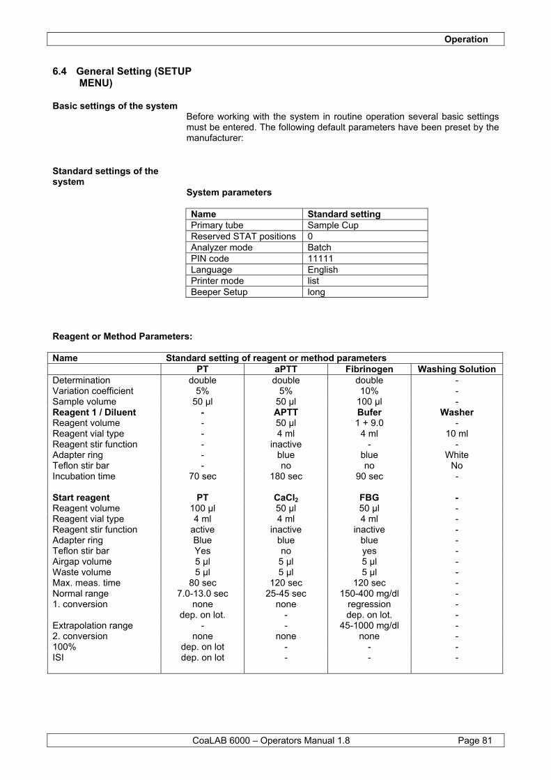
Operation
CoaLAB 6000 – Operators Manual 1.8 Page 81
6.4 General Setting (SETUP MENU)
Basic settings of the system Before working with the system in routine operation several basic settings must be entered. The following default parameters have been preset by the manufacturer:
Standard settings of the system
System parameters Name Standard setting Primary tube Sample Cup Reserved STAT positions 0 Analyzer mode Batch PIN code 11111 Language English Printer mode list Beeper Setup long
Reagent or Method Parameters: Name Standard setting of reagent or method parameters PT aPTT Fibrinogen Washing Solution Determination double double double - Variation coefficient 5% 5% 10% - Sample volume 50 µl 50 µl 100 µl - Reagent 1 / Diluent - APTT Bufer Washer Reagent volume - 50 µl 1 + 9.0 - Reagent vial type - 4 ml 4 ml 10 ml Reagent stir function - inactive - - Adapter ring - blue blue White Teflon stir bar - no no No Incubation time 70 sec 180 sec 90 sec - Start reagent PT CaCl2 FBG - Reagent volume 100 µl 50 µl 50 µl - Reagent vial type 4 ml 4 ml 4 ml - Reagent stir function active inactive inactive - Adapter ring Blue blue blue - Teflon stir bar Yes no yes - Airgap volume 5 µl 5 µl 5 µl - Waste volume 5 µl 5 µl 5 µl - Max. meas. time 80 sec 120 sec 120 sec - Normal range 7.0-13.0 sec 25-45 sec 150-400 mg/dl - 1. conversion none none regression - dep. on lot. - dep. on lot. - Extrapolation range - - 45-1000 mg/dl - 2. conversion none none none - 100% dep. on lot - - - ISI dep. on lot - - -
Operation
CoaLAB 6000 – Operators Manual 1.8 Page 82
If you want to change any of these settings follow the steps below:
6.4.1 Define Primary Tubes Before entering a joblist in routine operation the primary tubes can be selected. The system has a recommended number of different types. If you use the Sample cup which is preset by the manufacturer you can ignore the following instructions. • Use the arrow keys (</>) to select <4 SETUP MENU> in the MAIN MENU.
MAIN MENU: < 4 SETUP Menu >
• Press ENTER to confirm. The following display appears:
SETUP MENU: PIN
• Enter the PIN code with the number keys (default= 11111). • Press the arrow keys (</>) until <1 Primary Tube> is displayed in the
SETUP MENU. The following display appears:
SETUP MENU: < 1 Primary Tube >
• Press ENTER to confirm. The following display appears:
Primary Tube: < 1 Sample Cup >
The displayed primary tube is the type entered last. By pressing the arrow keys (</>) you can select another type.
If you do not wish to change any of the manufacturer’s preset default settings continue with ROUTINE operation, see section 6.1. NOTE
NOTE
NOTE
To secure perfect operation of the system only recommended primary tubes should be used.
Before getting access to the SETUP MENU a PIN code has to be entered with the number keys. The preset code is 11111. You can change this code by following the instructions as per chapter 6.4.6 SetPIN Code. Remember to write this code down and keep it at a safe place, accessible to authorised users only.
Operation
CoaLAB 6000 – Operators Manual 1.8 Page 83
• Press ENTER to confirm. The following list will give an overview of the primary tubes which can be used on the system.
Pos No. Primary Tube Dead volume Max. Volume Manufacturer 1 1 Sample Cup 150 µl 4.000 µl LABiTec 2 2 Vacutainer - 4.500 µl Beckton & Dickinson 3 3 Monovette - 3.000 µl Sarstedt
The following display appears:
SETUP MENU: < 1 Primary Tube >
• Press ESC to get back into the MAIN MENU.
6.4.2 Define STAT positions in the sample rotor
Follow the instructions to define or reserve STAT positions in the sample rotor. A maximum of 3 positions may be reserved for STAT samples. If no STAT positions have been reserved, the instrument will use the next free position available. • Use the arrow keys (</>) to select <4 SETUP MENU> in the MAIN MENU.
MAIN MENU: < 4 SETUP Menu >
• Press ENTER to confirm. The following display appears:
SETUP MENU: PIN
• Enter the PIN code with the number keys (default= 11111). • Press the arrow keys (</>) until <2 No of STAT pos.> is displayed in the
SETUP MENU. The following display appears:
SETUP MENU: < 2 No of STAT pos >
• Press ENTER to confirm.
NOTENever go below the recommended dead volume or results may be affected. Only one type can be used at a time. A mixture of tubes may damage the pipettor.
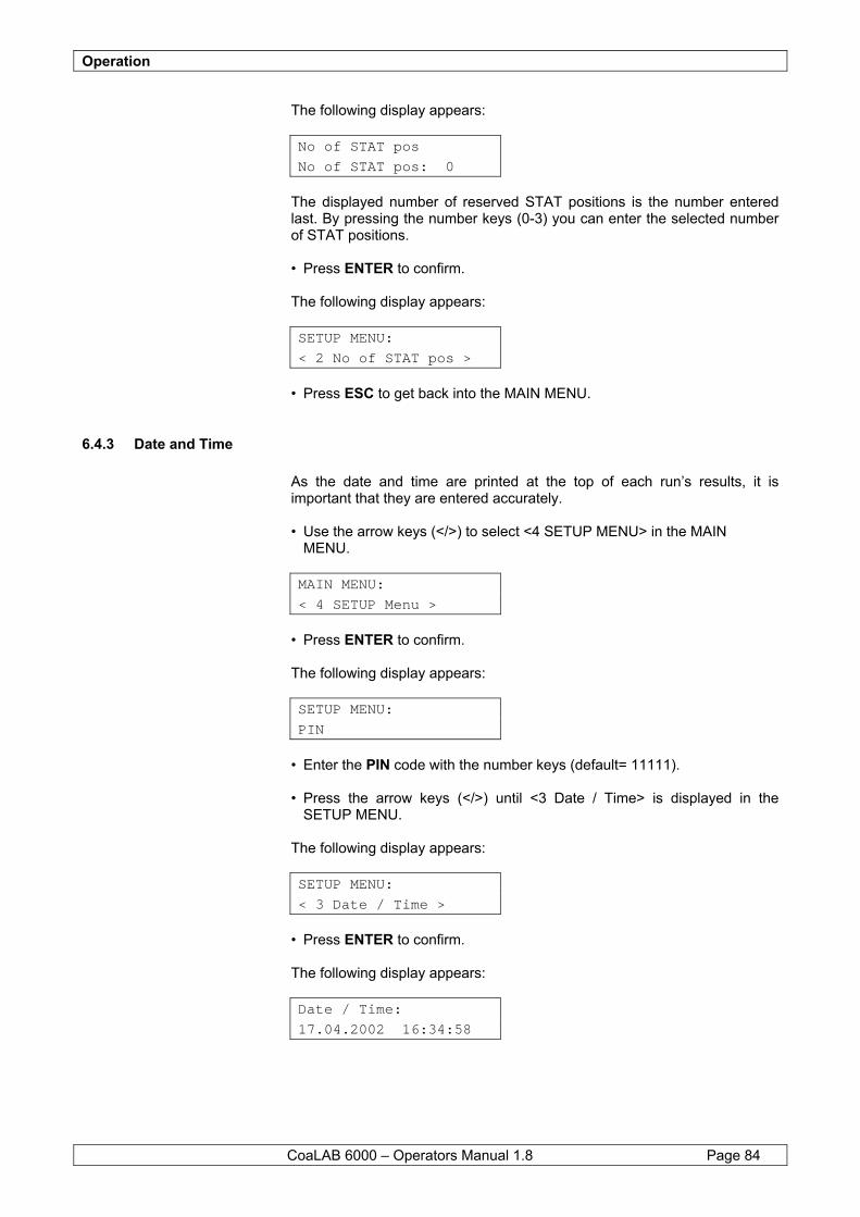
Operation
CoaLAB 6000 – Operators Manual 1.8 Page 84
The following display appears:
No of STAT pos No of STAT pos: 0
The displayed number of reserved STAT positions is the number entered last. By pressing the number keys (0-3) you can enter the selected number of STAT positions. • Press ENTER to confirm. The following display appears:
SETUP MENU: < 2 No of STAT pos >
• Press ESC to get back into the MAIN MENU.
6.4.3 Date and Time As the date and time are printed at the top of each run’s results, it is important that they are entered accurately. • Use the arrow keys (</>) to select <4 SETUP MENU> in the MAIN MENU.
MAIN MENU: < 4 SETUP Menu >
• Press ENTER to confirm. The following display appears:
SETUP MENU: PIN
• Enter the PIN code with the number keys (default= 11111). • Press the arrow keys (</>) until <3 Date / Time> is displayed in the SETUP MENU. The following display appears:
SETUP MENU: < 3 Date / Time >
• Press ENTER to confirm. The following display appears:
Date / Time: 17.04.2002 16:34:58
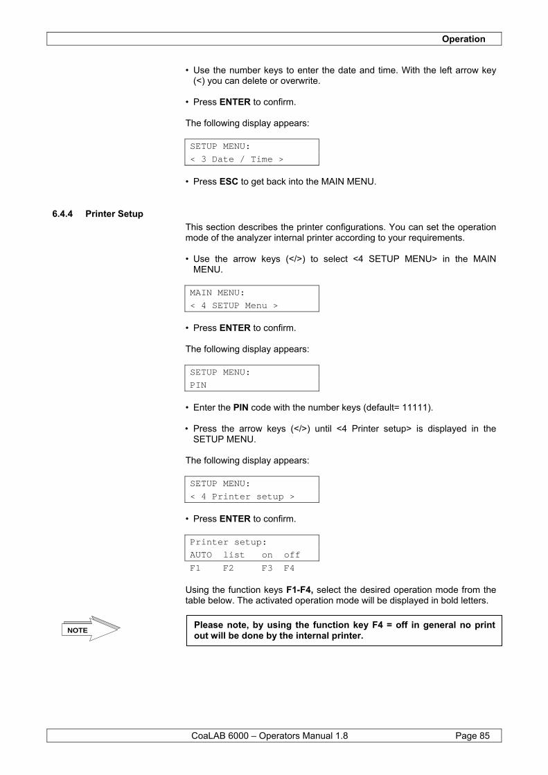
Operation
CoaLAB 6000 – Operators Manual 1.8 Page 85
• Use the number keys to enter the date and time. With the left arrow key (<) you can delete or overwrite.
• Press ENTER to confirm. The following display appears:
SETUP MENU: < 3 Date / Time >
• Press ESC to get back into the MAIN MENU.
6.4.4 Printer Setup This section describes the printer configurations. You can set the operation mode of the analyzer internal printer according to your requirements. • Use the arrow keys (</>) to select <4 SETUP MENU> in the MAIN MENU.
MAIN MENU: < 4 SETUP Menu >
• Press ENTER to confirm. The following display appears:
SETUP MENU: PIN
• Enter the PIN code with the number keys (default= 11111). • Press the arrow keys (</>) until <4 Printer setup> is displayed in the
SETUP MENU. The following display appears:
SETUP MENU: < 4 Printer setup >
• Press ENTER to confirm.
Printer setup: AUTO list on off F1 F2 F3 F4
Using the function keys F1-F4, select the desired operation mode from the table below. The activated operation mode will be displayed in bold letters.
NOTEPlease note, by using the function key F4 = off in general no print out will be done by the internal printer.
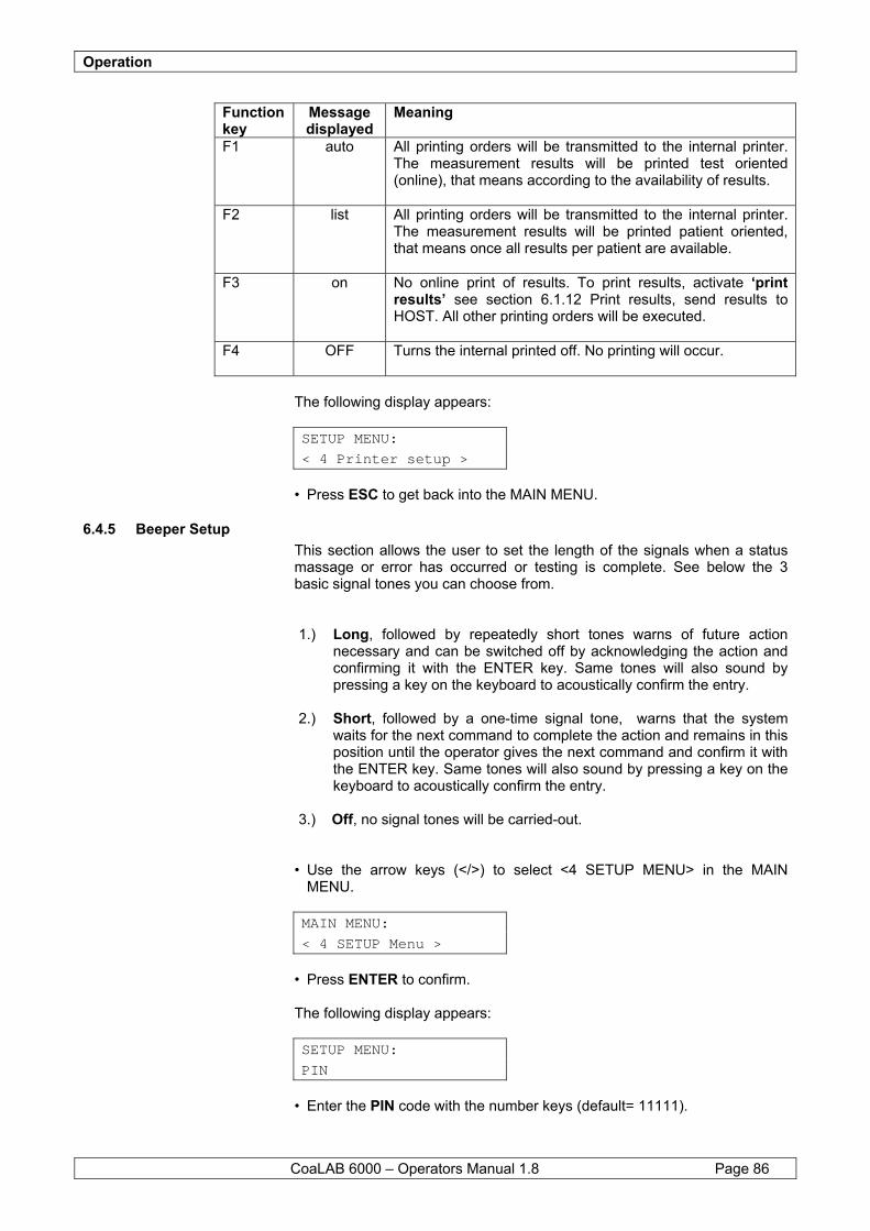
Operation
CoaLAB 6000 – Operators Manual 1.8 Page 86
Function key
Message displayed
Meaning
F1 auto All printing orders will be transmitted to the internal printer. The measurement results will be printed test oriented (online), that means according to the availability of results.
F2 list All printing orders will be transmitted to the internal printer. The measurement results will be printed patient oriented, that means once all results per patient are available.
F3 on No online print of results. To print results, activate ‘print results’ see section 6.1.12 Print results, send results to HOST. All other printing orders will be executed.
F4 OFF Turns the internal printed off. No printing will occur.
The following display appears:
SETUP MENU: < 4 Printer setup >
• Press ESC to get back into the MAIN MENU.
6.4.5 Beeper Setup This section allows the user to set the length of the signals when a status massage or error has occurred or testing is complete. See below the 3 basic signal tones you can choose from. 1.) Long, followed by repeatedly short tones warns of future action
necessary and can be switched off by acknowledging the action and confirming it with the ENTER key. Same tones will also sound by pressing a key on the keyboard to acoustically confirm the entry.
2.) Short, followed by a one-time signal tone, warns that the system
waits for the next command to complete the action and remains in this position until the operator gives the next command and confirm it with the ENTER key. Same tones will also sound by pressing a key on the keyboard to acoustically confirm the entry.
3.) Off, no signal tones will be carried-out.
• Use the arrow keys (</>) to select <4 SETUP MENU> in the MAIN MENU.
MAIN MENU: < 4 SETUP Menu >
• Press ENTER to confirm. The following display appears:
SETUP MENU: PIN
• Enter the PIN code with the number keys (default= 11111).
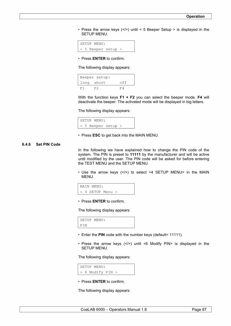
Operation
CoaLAB 6000 – Operators Manual 1.8 Page 87
• Press the arrow keys (</>) until < 5 Beeper Setup > is displayed in the SETUP MENU.
SETUP MENU: < 5 Beeper setup >
• Press ENTER to confirm. The following display appears:
Beeper setup: long short off F1 F2 F4
With the function keys F1 + F2 you can select the beeper mode. F4 will deactivate the beeper. The activated mode will be displayed in big letters. The following display appears:
SETUP MENU: < 5 Beeper setup >
• Press ESC to get back into the MAIN MENU.
6.4.6 Set PIN Code In the following we have explained how to change the PIN code of the system. The PIN is preset to 11111 by the manufacturer and will be active until modified by the user. The PIN code will be asked for before entering the TEST MENU and the SETUP MENU. • Use the arrow keys (</>) to select <4 SETUP MENU> in the MAIN MENU.
MAIN MENU: < 4 SETUP Menu >
• Press ENTER to confirm. The following display appears:
SETUP MENU: PIN
• Enter the PIN code with the number keys (default= 11111). • Press the arrow keys (</>) until <6 Modify PIN> is displayed in the SETUP MENU. The following display appears:
SETUP MENU: < 6 Modify PIN >
• Press ENTER to confirm. The following display appears:
Operation
CoaLAB 6000 – Operators Manual 1.8 Page 88
Modify PIN New PIN: 11111
The actual PIN code will be displayed. You can change it with the number keys. A maximum of 5 numbers can be entered. The PIN code has to be defined between 1 until 65535. Use the left arrow key (<) if you want to delete or overwrite your entry. • Press ENTER to confirm. The following display appears:
SETUP MENU: < 6 Modify PIN >
• Press ESC to get back into the MAIN MENU.
6.4.7 Language Follow the instructions if you want to change the language in the system. You can select between English and German. • Use the arrow keys (</>) to select <4 SETUP MENU> in the MAIN MENU.
MAIN MENU: < 4 SETUP Menu >
• Press ENTER to confirm. The following display appears:
SETUP MENU: PIN
• Enter the PIN code with the number keys (default= 11111). • Press the arrow keys (</>) until <7 Language> is displayed in the SETUP MENU. The following display appears:
SETUP MENU: < 7 Language >
• Press ENTER to confirm. The following display appears:
Select language: ENG deu end F1 F2 F4
The activated language will be displayed in big letters. With the function keys F1 = English and F2 = German you can select the desired language. If you press F4 = end you will leave this menu without changing anything.
Operation
CoaLAB 6000 – Operators Manual 1.8 Page 89
The following display appears:
SETUP MENU: < 7 Language >
• Press ESC to get back into the MAIN MENU.
6.4.8 Print of Setup Parameters
Follow the instructions to print the parameters described in section 6.4 General Setting (SETUP MENU) on the internal printer. Printing the SETUP parameters provides an overview of the general setup of the system. • Use the arrow keys (</>) to select <4 SETUP MENU> in the MAIN MENU.
MAIN MENU: < 4 SETUP Menu >
• Press ENTER to confirm. The following display appears:
SETUP MENU: PIN
• Enter the PIN code with the number keys (default= 11111). • Press the arrow keys (</>) until <8 Print Setup> is displayed in the
SETUP MENU.
SETUP MENU: < 8 Print Setup >
• Press ENTER to confirm. The following display appears:
Print Setup
The SETUP parameters will be printed on the internal printer. The following display appears:
SETUP MENU: < 8 Print Setup >
• Press ESC to get back into the MAIN MENU.

Operation
CoaLAB 6000 – Operators Manual 1.8 Page 90
6.5 Removing cuvette bars from the system
In the following chapter we have described how to remove cuvette bars from the measuring block. • Use the arrow keys (</>) to select <5 UTILITY MENU> in the MAIN
MENU.
MAIN MENU < 5 UTILITY MENU >
• Press ENTER to confirm. The following display appears:
UTILITY MENU: < 1 Init Instrument >
• Press ENTER to confirm the message. The following display appears:
Init Instrument Init ... (ESC=Stop)
The motors and the diluter will be initialised. During this phase the cuvette racks in the measuring block will be moved one position to the right and will be ejected from the measuring block. The following display appears:
Init Instrument Flush ... (ESC=Stop)
Then the liquid system will be initialised. Liquids are pumped into the tubing’s. • Press ESC if you want to finish initialisation. The following display appears:
UTILITY MENU: < 1 Init Instrument >
• Press ESC to get back into the MAIN MENU.
6.6 Switch OFF the system Prior to switching off the system make sure the system is cleaned and disinfected from all residues of reagent and sample material inside the liquid system as well as from the outer side of the analyzer. Depending on how long you would like to shut down the system it is necessary to follow different wash/flush cycles to avoid any residues of reagents/samples will remain in the liquid system. To clean/disinfect the system follow the instructions as described in sections 6.1.2 Rinsing with distilled water, 6.1.3 Disinfection of waste tubing (Terralin), change of FW-Filter or 6.1.4 Rinsing with Washing Solution.
Operation
CoaLAB 6000 – Operators Manual 1.8 Page 91
In case of a long term shut down it is recommended to also dry the system completely. Follow the instructions in section 8.8 Packing of the system, preparation of transport as described under 3. - 6. This procedure should be done if the shut down time exceeds 4 weeks. Remove all reagents must be removed from the sample/reagent rotor. Follow the instructions in section 6.1.5 Loading and unloading reagents. Remove all samples/cups from the sample/reagent rotor positions 1-18 by erasing the joblist. Follow the instructions described in section 6.1.6 Delete joblist, delete samples. Make sure all results of the current joblist are printed out prior to erasing the joblist. Once the joblist has been deleted no results will be available anymore. Make sure that finally the instrument is free of cuvette bars, vials, cups and adapter rings. Now the system can be switched OFF by setting the power switch to the position O = ON.

Operation
CoaLAB 6000 – Operators Manual 1.8 Page 92
7 Failures Possible error messages, their causes and trouble shooting are described in this section. These failures or status messages can be displayed as well as printed. The messages will be differentiated according to the following scheme:
Status messages: System messages for the general information of the user. These are no errors/failures.
Application errors: Failures/errors to be corrected by the user.
Non-fatal errors: Functional system errors to be corrected by the user.
Fatal errors: Errors to be corrected by the technical customer service only. Contact your authorised distributor or the manufacturer.
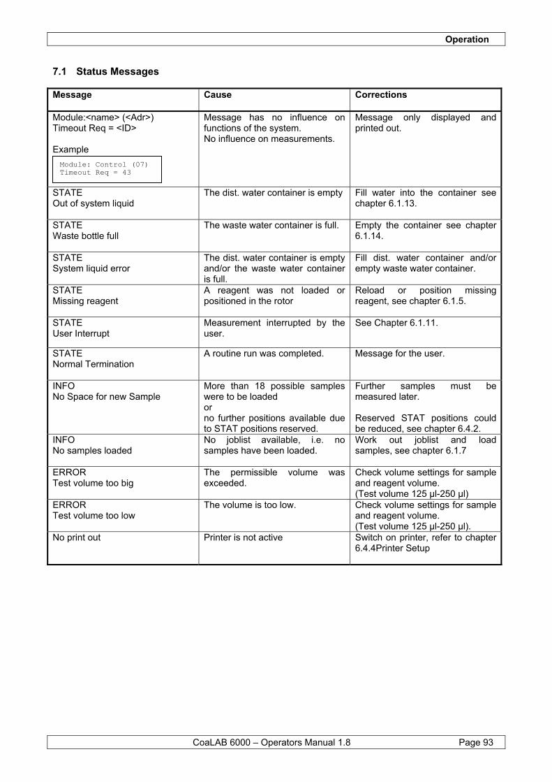
Operation
CoaLAB 6000 – Operators Manual 1.8 Page 93
7.1 Status Messages
Message
Cause Corrections
Module:<name> (<Adr>) Timeout Req = <ID> Example
Message has no influence on functions of the system. No influence on measurements.
Message only displayed and printed out.
STATE Out of system liquid
The dist. water container is empty Fill water into the container see chapter 6.1.13.
STATE Waste bottle full
The waste water container is full. Empty the container see chapter 6.1.14.
STATE System liquid error
The dist. water container is empty and/or the waste water container is full.
Fill dist. water container and/or empty waste water container.
STATE Missing reagent
A reagent was not loaded or positioned in the rotor
Reload or position missing reagent, see chapter 6.1.5.
STATE User Interrupt
Measurement interrupted by the user.
See Chapter 6.1.11.
STATE Normal Termination
A routine run was completed. Message for the user.
INFO No Space for new Sample
More than 18 possible samples were to be loaded or no further positions available due to STAT positions reserved.
Further samples must be measured later. Reserved STAT positions could be reduced, see chapter 6.4.2.
INFO No samples loaded
No joblist available, i.e. no samples have been loaded.
Work out joblist and load samples, see chapter 6.1.7
ERROR Test volume too big
The permissible volume was exceeded.
Check volume settings for sample and reagent volume. (Test volume 125 µl-250 µl)
ERROR Test volume too low
The volume is too low. Check volume settings for sample and reagent volume. (Test volume 125 µl-250 µl).
No print out Printer is not active Switch on printer, refer to chapter 6.4.4Printer Setup
Module: Control (07) Timeout Req = 43
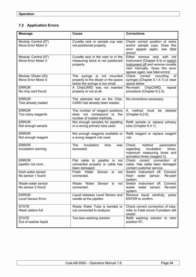
Operation
CoaLAB 6000 – Operators Manual 1.8 Page 94
7.2 Application Errors
Message
Cause Corrections
Module: Control (07) Move Error Motor 0
Cuvette rack or sample cup was not positioned properly.
Check correct position of racks and/or sample cups. Does this error appear again, see fatal errors!
Module: Control (07) Move Error Motor 3
Cuvette rack in the rotor or in the measuring block is not positioned properly.
Either remove rack with Init Instrument (Chapter 6.5) or switch Instrument off and remove cuvette rack manually. Does this error appear again, see fatal errors!
Module: Diluter (03) Move Error Motor 0
The syringe is not mounted properly to the diluter or the space below the syringe is too small.
Check correct mounting of syringes (Chapter 5.1.4.1) or clear space below
ERROR No chip card found
A ChipCARD was not inserted properly or not at all.
Re-insert ChipCARD, repeat procedure (Chapter 6.2.3).
ERROR Test already loaded
The selected test on the Chip- CARD had already been loaded.
No corrections necessary.
ERROR Too many reagents
The number of reagent positions does not correspond to the number of loaded methods.
A method must be deleted (Chapter 6.2.6).
ERROR Not enough sample
Not enough samples for pipetting or a wrong primary tube used.
Refill sample or replace primary tube (Chapter 6.4.1).
ERROR Not enough reagent
Not enough reagents available or a wrong reagent vial used.
Refill reagent or replace reagent vial.
ERROR Incubation warning
The incubation time was exceeded.
Check method parameters regarding incubation times, maximum measuring times and activation times (reagent 3).
ERROR pipettor not conn.
Flat cable to pipettor is not connected properly or cable has been damaged.
Check correct connection of cable. Has cable been damaged contact customer service.
fresh water sensor No sensor 1 found
Fresh Water Sensor is not connected.
Switch Instrument off. Connect fresh water sensor. Re-start system.
Waste water sensor No sensor 2 found
Waste Water Sensor is not connected.
Switch Instrument off. Connect waste water sensor. Re-start system.
ERROR Level Sensor Error
Liquid between Level Sensor and needle at the pipettor
Remove liquid carefully, press ENTER to confirm.
STATE Wash station full
Waste Water Tube is bended or not connected to analyzer
Check correct connection of tube; refer to Fatal errors if problem still exists!
STATE Out of washer liquid
Too less washing solution Refill washing solution to rotor position R1.
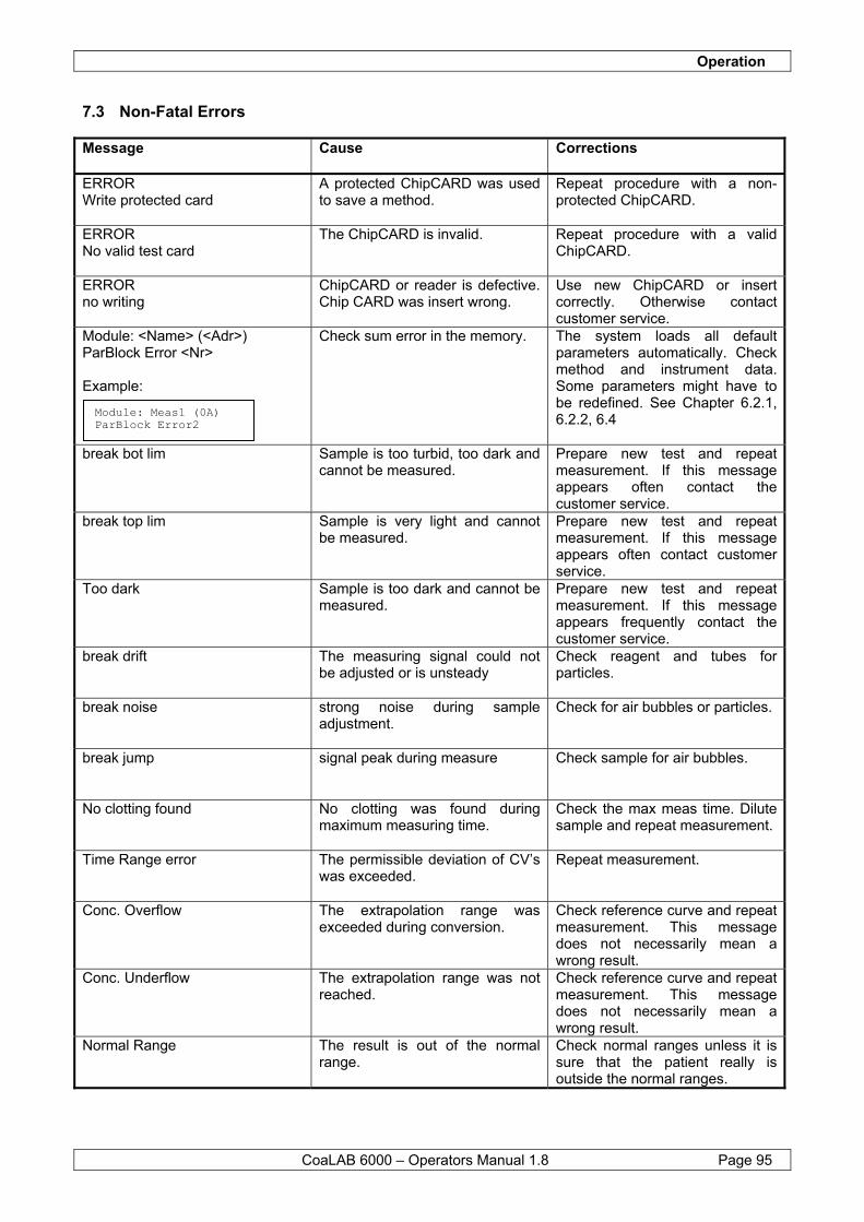
Operation
CoaLAB 6000 – Operators Manual 1.8 Page 95
7.3 Non-Fatal Errors
Message
Cause Corrections
ERROR Write protected card
A protected ChipCARD was used to save a method.
Repeat procedure with a non-protected ChipCARD.
ERROR No valid test card
The ChipCARD is invalid. Repeat procedure with a valid ChipCARD.
ERROR no writing
ChipCARD or reader is defective. Chip CARD was insert wrong.
Use new ChipCARD or insert correctly. Otherwise contact customer service.
Module: <Name> (<Adr>) ParBlock Error <Nr> Example:
Check sum error in the memory. The system loads all default parameters automatically. Check method and instrument data. Some parameters might have to be redefined. See Chapter 6.2.1, 6.2.2, 6.4
break bot lim
Sample is too turbid, too dark and cannot be measured.
Prepare new test and repeat measurement. If this message appears often contact the customer service.
break top lim Sample is very light and cannot be measured.
Prepare new test and repeat measurement. If this message appears often contact customer service.
Too dark Sample is too dark and cannot be measured.
Prepare new test and repeat measurement. If this message appears frequently contact the customer service.
break drift The measuring signal could not be adjusted or is unsteady
Check reagent and tubes for particles.
break noise strong noise during sample adjustment.
Check for air bubbles or particles.
break jump signal peak during measure
Check sample for air bubbles.
No clotting found No clotting was found during maximum measuring time.
Check the max meas time. Dilute sample and repeat measurement.
Time Range error The permissible deviation of CV’s was exceeded.
Repeat measurement.
Conc. Overflow The extrapolation range was exceeded during conversion.
Check reference curve and repeat measurement. This message does not necessarily mean a wrong result.
Conc. Underflow The extrapolation range was not reached.
Check reference curve and repeat measurement. This message does not necessarily mean a wrong result.
Normal Range The result is out of the normal range.
Check normal ranges unless it is sure that the patient really is outside the normal ranges.
Module: Meas1 (0A) ParBlock Error2
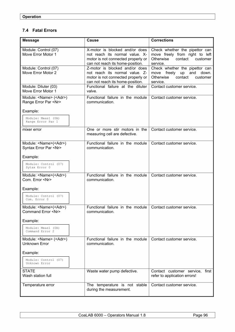
Operation
CoaLAB 6000 – Operators Manual 1.8 Page 96
7.4 Fatal Errors
Message
Cause Corrections
Module: Control (07) Move Error Motor 1
X-motor is blocked and/or does not reach its normal value. X-motor is not connected properly or can not reach its home-position.
Check whether the pipettor can move freely from right to left Otherwise contact customer service.
Module: Control (07) Move Error Motor 2
Z-motor is blocked and/or does not reach its normal value. Z-motor is not connected properly or can not reach its home-position.
Check whether the pipettor can move freely up and down. Otherwise contact customer service.
Module: Diluter (03) Move Error Motor 1
Functional failure at the diluter valve.
Contact customer service.
Module: <Name> (<Adr>) Range Error Par <Nr> Example:
Functional failure in the module communication.
Contact customer service.
mixer error One or more stir motors in the measuring cell are defective.
Contact customer service.
Module: <Name>(<Adr>) Syntax Error Par <Nr> Example:
Functional failure in the module communication.
Contact customer service.
Module: <Name>(<Adr>) Com. Error <Nr> Example:
Functional failure in the module communication.
Contact customer service.
Module: <Name>(<Adr>) Command Error <Nr> Example:
Functional failure in the module communication.
Contact customer service.
Module: <Name> (<Adr>) Unknown Error Example:
Functional failure in the module communication.
Contact customer service.
STATE Wash station full
Waste water pump defective. Contact customer service, first refer to application errors!
Temperature error The temperature is not stable during the measurement.
Contact customer service.
Module: Meas1 (0A) Range Error Par 1
Module: Control (07) Sytax Error 0
Module: Control (07) Com. Error 0
Module: Meas1 (0A) Command Error 2
Module: Control (07) Unknown Error
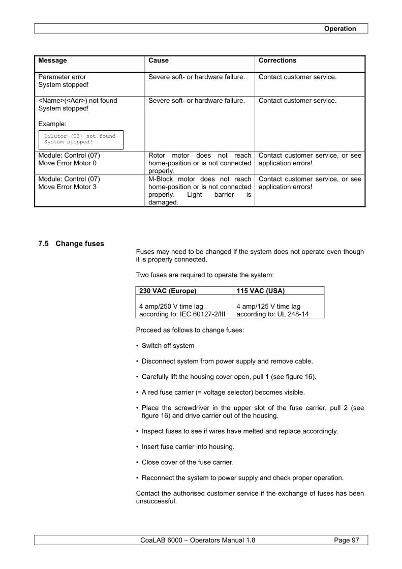
Operation
CoaLAB 6000 – Operators Manual 1.8 Page 97
Message
Cause Corrections
Parameter error System stopped!
Severe soft- or hardware failure. Contact customer service.
<Name>(<Adr>) not found System stopped! Example:
Severe soft- or hardware failure. Contact customer service.
Module: Control (07) Move Error Motor 0
Rotor motor does not reach home-position or is not connected properly.
Contact customer service, or see application errors!
Module: Control (07) Move Error Motor 3
M-Block motor does not reach home-position or is not connected properly. Light barrier is damaged.
Contact customer service, or see application errors!
7.5 Change fuses Fuses may need to be changed if the system does not operate even though it is properly connected. Two fuses are required to operate the system: 230 VAC (Europe) 115 VAC (USA) 4 amp/250 V time lag according to: IEC 60127-2/III
4 amp/125 V time lag according to: UL 248-14
Proceed as follows to change fuses: • Switch off system • Disconnect system from power supply and remove cable. • Carefully lift the housing cover open, pull 1 (see figure 16). • A red fuse carrier (= voltage selector) becomes visible. • Place the screwdriver in the upper slot of the fuse carrier, pull 2 (see
figure 16) and drive carrier out of the housing. • Inspect fuses to see if wires have melted and replace accordingly. • Insert fuse carrier into housing. • Close cover of the fuse carrier. • Reconnect the system to power supply and check proper operation. Contact the authorised customer service if the exchange of fuses has been unsuccessful.
Dilutor (03) not found System stopped!
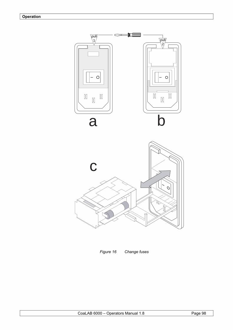
Operation
CoaLAB 6000 – Operators Manual 1.8 Page 98
BIS HIER !
Figure 16 Change fuses
a b
c
pull1 pull
2
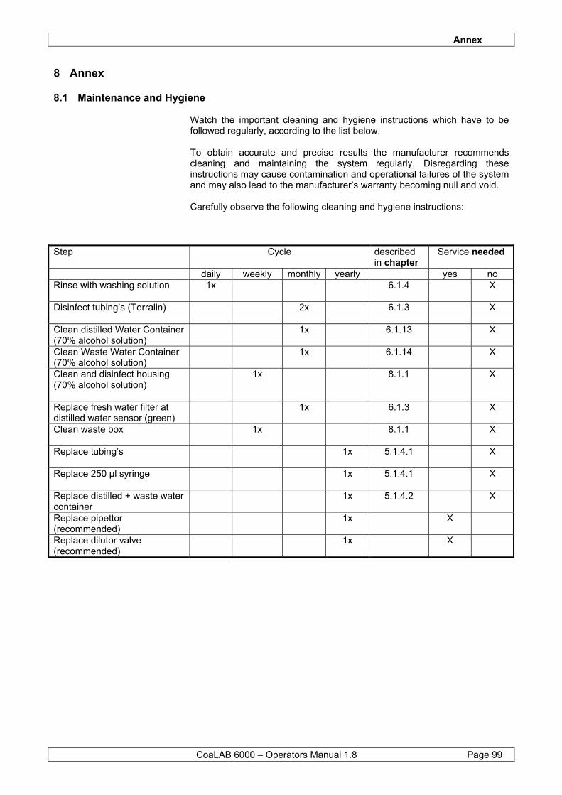
Annex
CoaLAB 6000 – Operators Manual 1.8 Page 99
8 Annex
8.1 Maintenance and Hygiene Watch the important cleaning and hygiene instructions which have to be followed regularly, according to the list below. To obtain accurate and precise results the manufacturer recommends cleaning and maintaining the system regularly. Disregarding these instructions may cause contamination and operational failures of the system and may also lead to the manufacturer’s warranty becoming null and void. Carefully observe the following cleaning and hygiene instructions:
Step Cycle described
in chapter Service needed
daily weekly monthly yearly yes no Rinse with washing solution
1x 6.1.4 X
Disinfect tubing’s (Terralin)
2x 6.1.3 X
Clean distilled Water Container (70% alcohol solution)
1x 6.1.13 X
Clean Waste Water Container (70% alcohol solution)
1x 6.1.14 X
Clean and disinfect housing (70% alcohol solution)
1x 8.1.1 X
Replace fresh water filter at distilled water sensor (green)
1x 6.1.3 X
Clean waste box 1x 8.1.1 X
Replace tubing’s 1x 5.1.4.1 X
Replace 250 µl syringe 1x 5.1.4.1 X
Replace distilled + waste water container
1x 5.1.4.2 X
Replace pipettor (recommended)
1x X
Replace dilutor valve (recommended)
1x X
Annex
CoaLAB 6000 – Operators Manual 1.8 Page 100
8.1.1 Cleaning and Disinfection of housing and waste box
Once a week the housing and the waste box should be cleaned and disinfected to avoid any contamination.
Do not use any organic acids to clean the instrument and the waste box. Only use a cleaner designed for cleaning and disinfecting instrument surfaces and waste box. Use a dampened cloth. Never spray or pour any liquids onto or into the system which may negatively impact the analyzer’s functions. If liquids have accidentally run into the system contact the customer service of the distributor or the manufacturer.
8.1.2 How to dispose of used disposables
Remember to dispose of used cuvette racks, primary tubes, and reagent vials in compliance with legal provisions.
8.1.3 How to dispose the used system
NOTE Do not use organic acids.
Avoid any direct skin contact with samples and/or test reagents as well as those parts of the instrument which might be contaminated with samples and/or test reagents. These parts are potentially infectious. If samples were spilled onto the system wipe them off immediately and disinfect the instrument. Reagents might irritate the skin or mucous membranes. Observe the manufacturer’s instructions in the package insert how to handle the reagents properly. Make sure to dispose of the sample and test material in compliance with biohazard and legal provisions.
NOTE
All disposables used with the system must be treated as potentially infectious. Avoid any skin contact with sample and reagent material which might be on the disposables. Dispose of used disposables in compliance with legal provisions or laboratory regulations. Do not put used disposables, samples and reagents into the usual garbage. Cuvette racks might not be resistant to organic acids. Therefore do not use organic acids unless they are expressly permitted.
NOTE
Remember the disposal of the used complete system incl. all tubing’s, syringe etc. must be done in compliance with all relating legal provisions. The used system and its parts are hazardous waste and must be treated as potential infectious. Ask your local dealer or distributor for further directions.
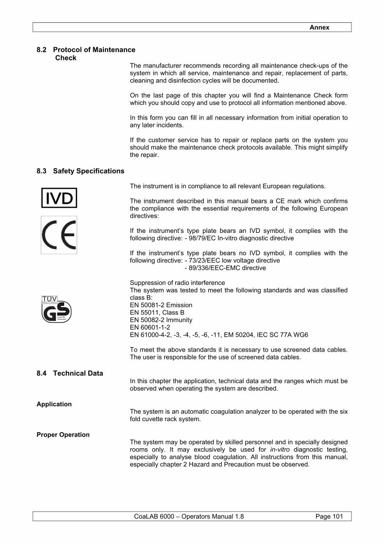
Annex
CoaLAB 6000 – Operators Manual 1.8 Page 101
8.2 Protocol of Maintenance Check
The manufacturer recommends recording all maintenance check-ups of the system in which all service, maintenance and repair, replacement of parts, cleaning and disinfection cycles will be documented. On the last page of this chapter you will find a Maintenance Check form which you should copy and use to protocol all information mentioned above. In this form you can fill in all necessary information from initial operation to any later incidents. If the customer service has to repair or replace parts on the system you should make the maintenance check protocols available. This might simplify the repair.
8.3 Safety Specifications The instrument is in compliance to all relevant European regulations. The instrument described in this manual bears a CE mark which confirms the compliance with the essential requirements of the following European directives: If the instrument’s type plate bears an IVD symbol, it complies with the following directive: - 98/79/EC In-vitro diagnostic directive If the instrument’s type plate bears no IVD symbol, it complies with the following directive: - 73/23/EEC low voltage directive - 89/336/EEC-EMC directive Suppression of radio interference The system was tested to meet the following standards and was classified class B: EN 50081-2 Emission EN 55011, Class B EN 50082-2 Immunity EN 60601-1-2 EN 61000-4-2, -3, -4, -5, -6, -11, EM 50204, IEC SC 77A WG6 To meet the above standards it is necessary to use screened data cables. The user is responsible for the use of screened data cables.
8.4 Technical Data In this chapter the application, technical data and the ranges which must be observed when operating the system are described.
Application The system is an automatic coagulation analyzer to be operated with the six fold cuvette rack system.
Proper Operation The system may be operated by skilled personnel and in specially designed rooms only. It may exclusively be used for in-vitro diagnostic testing, especially to analyse blood coagulation. All instructions from this manual, especially chapter 2 Hazard and Precaution must be observed.
IVDIVD
GeprüfteSicherheit
PRODUCT SERVICE
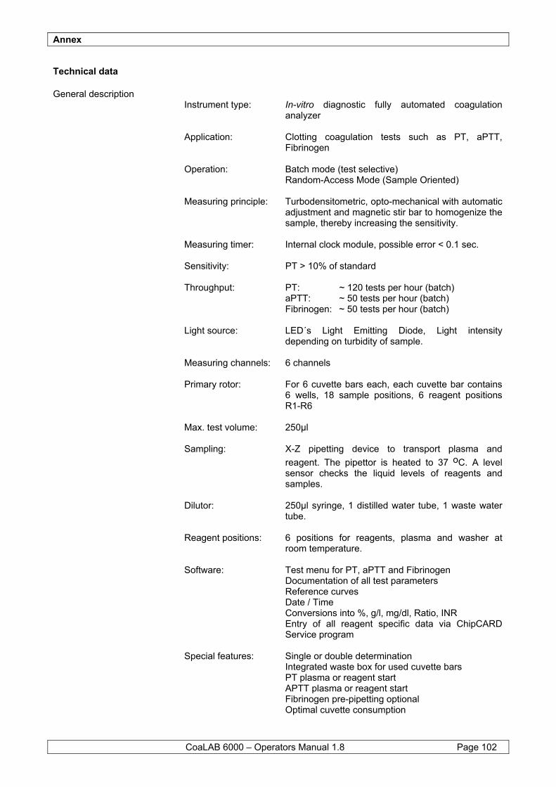
Annex
CoaLAB 6000 – Operators Manual 1.8 Page 102
Technical data
General description Instrument type: In-vitro diagnostic fully automated coagulation
analyzer Application: Clotting coagulation tests such as PT, aPTT,
Fibrinogen Operation: Batch mode (test selective)
Random-Access Mode (Sample Oriented) Measuring principle: Turbodensitometric, opto-mechanical with automatic
adjustment and magnetic stir bar to homogenize the sample, thereby increasing the sensitivity.
Measuring timer: Internal clock module, possible error < 0.1 sec. Sensitivity: PT > 10% of standard Throughput: PT: ~ 120 tests per hour (batch)
aPTT: ~ 50 tests per hour (batch) Fibrinogen: ~ 50 tests per hour (batch)
Light source: LED´s Light Emitting Diode, Light intensity
depending on turbidity of sample. Measuring channels: 6 channels Primary rotor: For 6 cuvette bars each, each cuvette bar contains
6 wells, 18 sample positions, 6 reagent positions R1-R6
Max. test volume: 250µl Sampling: X-Z pipetting device to transport plasma and
reagent. The pipettor is heated to 37 oC. A level sensor checks the liquid levels of reagents and samples.
Dilutor: 250µl syringe, 1 distilled water tube, 1 waste water
tube. Reagent positions: 6 positions for reagents, plasma and washer at
room temperature. Software: Test menu for PT, aPTT and Fibrinogen
Documentation of all test parameters Reference curves Date / Time Conversions into %, g/l, mg/dl, Ratio, INR Entry of all reagent specific data via ChipCARD Service program
Special features: Single or double determination
Integrated waste box for used cuvette bars PT plasma or reagent start APTT plasma or reagent start Fibrinogen pre-pipetting optional Optimal cuvette consumption
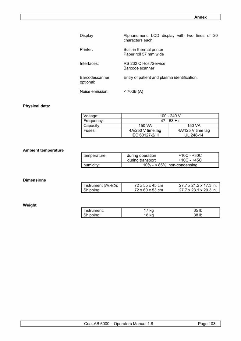
Annex
CoaLAB 6000 – Operators Manual 1.8 Page 103
Display Alphanumeric LCD display with two lines of 20
characters each. Printer: Built-in thermal printer
Paper roll 57 mm wide Interfaces: RS 232 C Host/Service
Barcode scanner Barcodescanner optional:
Entry of patient and plasma identification.
Noise emission: < 70dB (A)
Physical data: Voltage: 100 - 240 V Frequency: 47 - 63 Hz Capacity: 150 VA 150 VA Fuses: 4A/250 V time lag
IEC 60127-2/III 4A/125 V time lag
UL 248-14
Ambient temperature temperature: during operation +10C - +30C during transport +10C - +45C humidity: 10% - < 85%, non-condensing
Dimensions Instrument (WxHxD): 72 x 55 x 45 cm 27.7 x 21.2 x 17.3 in. Shipping: 72 x 60 x 53 cm 27.7 x 23.1 x 20.3 in.
Weight Instrument: 17 kg 35 lb Shipping: 18 kg 38 lb
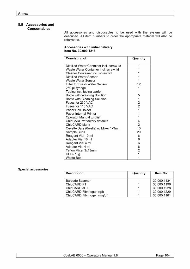
Annex
CoaLAB 6000 – Operators Manual 1.8 Page 104
8.5 Accessories and Consumables
All accessories and disposables to be used with the system will be described. All item numbers to order the appropriate material will also be referred to. Accessories with initial delivery Item No. 30.000.1218 Consisting of: Quantity Distilled Water Container incl. screw lid 1 Waste Water Container incl. screw lid 1 Cleaner Container incl. screw lid 1 Distilled Water Sensor 1 Waste Water Sensor 1 Filter for Fresh Water Sensor 12 250 µl syringe 1 Tubing incl. tubing carrier 1 Bottle with Washing Solution 5 Bottle with Cleaning Solution 1 Fuses for 230 VAC 2 Fuses for 115 VAC 2 Paper Roll Holder 1 Paper Internal Printer 1 Operator Manual English 1 ChipCARD w/ factory defaults 4 ChipCARD blank 2 Cuvette Bars (6wells) w/ Mixer 1x3mm 10 Sample Cups 20 Reagent Vial 10 ml 6 Adapter Vial 10 ml 6 Reagent Vial 4 ml 6 Adapter Vial 4 ml 6 Teflon Mixer 3x13mm 2 CPC-Plug 1 Waste Box 1
Special accessories Description Quantity Item No.: Barcode Scanner 1 30.000.1134 ChipCARD PT 1 30.000.1196 ChipCARD aPTT 1 30.000.1228 ChipCARD Fibrinogen (g/l) 1 30.000.1229 ChipCARD Fibrinogen (mg/dl) 1 30.000.1161
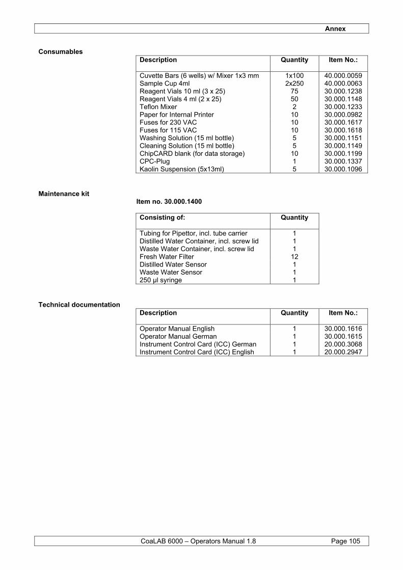
Annex
CoaLAB 6000 – Operators Manual 1.8 Page 105
Consumables Description Quantity Item No.: Cuvette Bars (6 wells) w/ Mixer 1x3 mm 1x100 40.000.0059 Sample Cup 4ml 2x250 40.000.0063 Reagent Vials 10 ml (3 x 25) 75 30.000.1238 Reagent Vials 4 ml (2 x 25) 50 30.000.1148 Teflon Mixer 2 30.000.1233 Paper for Internal Printer 10 30.000.0982 Fuses for 230 VAC 10 30.000.1617 Fuses for 115 VAC 10 30.000.1618 Washing Solution (15 ml bottle) 5 30.000.1151 Cleaning Solution (15 ml bottle) 5 30.000.1149 ChipCARD blank (for data storage) 10 30.000.1199 CPC-Plug 1 30.000.1337 Kaolin Suspension (5x13ml) 5 30.000.1096
Maintenance kit Item no. 30.000.1400 Consisting of: Quantity Tubing for Pipettor, incl. tube carrier 1 Distilled Water Container, incl. screw lid 1 Waste Water Container, incl. screw lid Fresh Water Filter
1 12
Distilled Water Sensor 1 Waste Water Sensor 1 250 µl syringe 1
Technical documentation Description Quantity Item No.: Operator Manual English 1 30.000.1616 Operator Manual German 1 30.000.1615 Instrument Control Card (ICC) German 1 20.000.3068 Instrument Control Card (ICC) English 1 20.000.2947
Annex
CoaLAB 6000 – Operators Manual 1.8 Page 106
8.6 Mathematics
Conversion Ranges The conversion ranges are fixed in method parameterisation program and cannot be modified by the user.
Interpolation: Polygonal: from measuring point to measuring point Regression: optimised line of all measuring points
Extrapolation: PT: > 100% Extrapolation over the last two upper measuring points Extrapolation factor: 1.5 PT: < 10% Extrapolation over the last two lower measuring points Extrapolation factor: 0.5 Fibrinogen: Extrapolation over the last two measuring points
Conversion to INR: INR = PT - RatioISI INR = International Normalised Ratio
PT-Ratio = measured value in seconds divided by 100% value in seconds
ISI = International Sensitivity Index according to package insert
8.7 Adaptation of coagulation reagents
In ROUTINE MENU you can install a maximum of three different methods. In general a wide variety of coagulation reagents can be used on the system. Remember that not for all reagents on the market a suggestion of adaptation could be determined by manufacturer. The use of different reagents may require specific changing’s on the system settings. On request manufacturer will only provide a suggestion on how to adapt some specific reagents on the system. The responsible adaptation and release of reagents is object to users respectively distributors internal laboratory regulations. Add a kaolin suspension to the reagent for fibrinogen determinations. All reagents can be stirred with the stir bar (2 pieces supplied). For further information with regard to adaptation of reagents contact the Service + Support Department of the manufacturer or your local Distributor.
Annex
CoaLAB 6000 – Operators Manual 1.8 Page 107
8.8 Packing of the system, preparation of transport
Adhere to the following instructions when transporting the system (e.g. for service reasons). Use only those packing materials received initially with the instrument. 1 If the system has been used, ensure the housing, sample/reagent
rotor and waste box have been disinfected thoroughly, see Section 8.1 Maintenance and Hygiene.
2 All tubing’s, distilled water and waste water tubes must be rinsed thoroughly before packing. See Section 6.1.3 Disinfection of waste tubing (Terralin), change of FW-Filter for further information.
3 Empty the dist. water pump so it will not be damaged during transport due to possible temperature fluctuations.
4 Disconnect adapter of fresh water tubing on the back side of the system, see Section 5.1.4.2.
5 Replace with the CPC-connector provided in the accessory box. To empty the distilled water pump remove the distilled water tube from the container and hold it over a sink. Then rinse the tubing 5 times, see Section 6.1.2. Stop this procedure immediately if you hear an abnormal sucking noise from the pump.
6 Remove the CPC-connector and return it into the accessory box.
7 Empty and clean the distilled and waste water containers as described in Section 6.1.13 and 6.1.14 for further information.
8 Remove all cuvette bars, primary tubes and reagent vials from the system.
9 Secure the system with all transport protection devices as per Section 5.1.3 Unpacking the system.
10 Pack all accessories into the supplied boxes and carefully close them.
11 Pack the system into the foam parts and place it into the outer box.
12 Place the accessory box into the outer box.
13 Close the carton carefully.