Embed Size (px)
Citation preview
Operator’s Manual for Rotary Set Up for LaserWORKS v8
608 Trestle Point Sanford, FL 32771
Phone 888-652-1555 • Fax 407-878-0880 www.BOSSLASER.com
BossLaser.com
LaserWORKS Rotary Set Up The rotary, either the roller or chuck type, plug in and work the same way. The y-axis is replaced with the rotary axis..
*MAKE SURE THE MACHINE IS TURNED OFF BEFORE PROCEEDING*
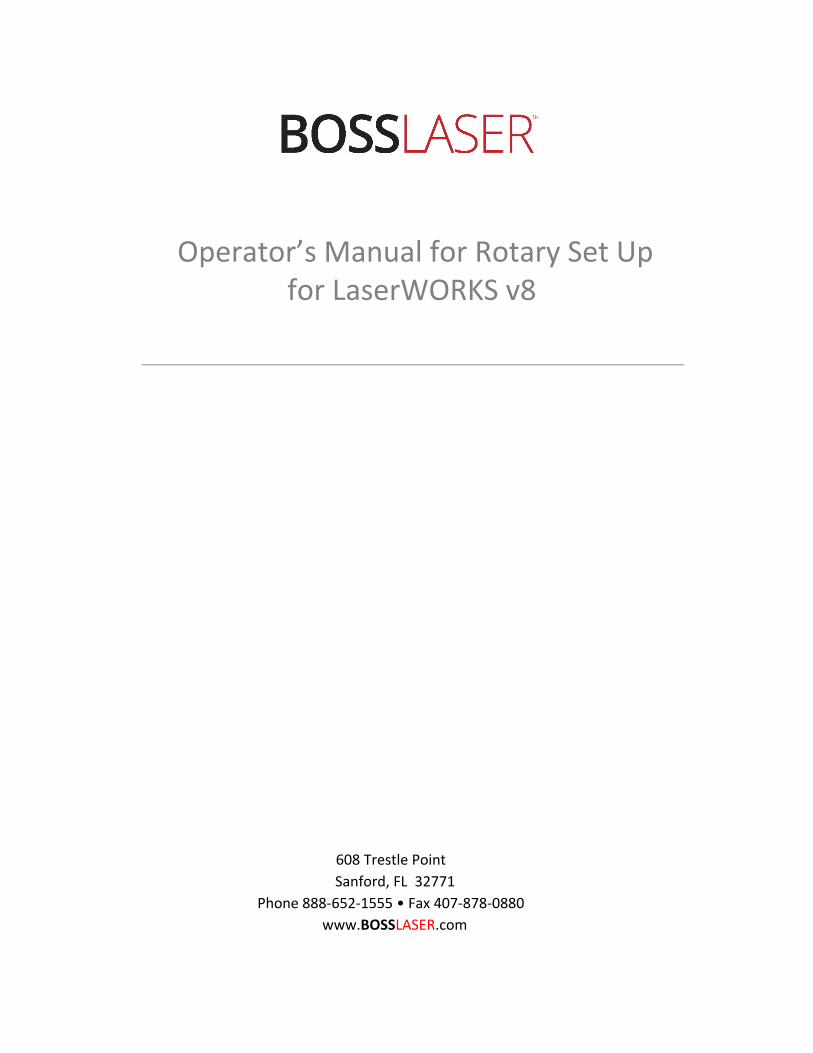
Hardware Rotary Set upRemove the Y-Axis connector as shown in Figure 1. Then plug in the rotary’s 4-pin female connector in place of the Y-Axis connector. Figure 1a shows the rotary connector outlet located on right side, top door panel near the DATUM point for a LS-1416 model. For the larger models (LS/HP-1630s, 2436s & 3655s), it is located inside towards the back of the machine labeledY-Axis Connector, as shown in Figure 1b. Finally, line the rotary up with the gantry (the metalbeam where the laser head rests on).
Figure 1a Figure 1b
Important!If the image looks mirrored vertically/horizontally, move the motor side of the rotary
to the opposite side of the table by rotating the rotary 180 degrees.
Now turn the machine on and let the laser head return to the home position. Since you unplugged the Y-Axis connector with the rotary attachment, you’ll notice that the laser head will only go to the right until it hits the X-Axis limit switch. This is normal and what it should be doing. The same motion needs to be done with the Y-Axis limit switch. To do so, move & push the gantry all the way to the back of the machine to trigger the Y-Axis limit switch. Notice after doing so, the laser head moves to the left and back towards the X-Axis limit switch. You will then need to copy this motion with the Y-Axis limit switch (bring it forward, away from the limit switch, then back towards it). Doing so, the rotary is correctly adjusted with the corresponding coordinates of your worktable and now should be ready to be used. Before continuing to the software portion of the set up, plug in the Blue USB cable located from the controller card of the machine into the PC.
BossLaser.com 888 652-1555
BossLaser.com
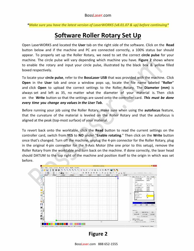
*Make sure you have the latest version of LaserWORKS (v8.01.07 & up) before continuing*
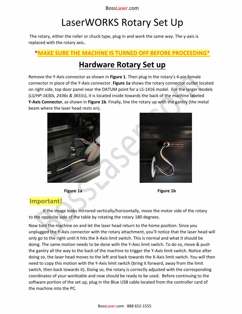
Software Roller Rotary Set Up Open LaserWORKS and located the User tab on the right side of the software. Click on the Read button below and if the machine and PC are connected correctly, a 100% status bar should appear. To properly set up the Roller Rotary, we need to set the correct circle pulse for your machine. The circle pulse will vary depending which machine you have. Figure 2 shows where to enable the rotary and input your circle pulse, illustrated by the black box & yellow filled boxed respectively.
To locate your circle pulse, refer to the BossLaser USB that was provided with the machine. Click Open in the User tab and once a window pops up, locate the file name labeled "Roller" and click Open to upload the correct settings to the Roller Rotary. The Diameter (mm) is always set and left as 35, no matter what the diameter of your material is. Then click on the Write button so that the settings are saved onto the controller card. This must be done every time you change any values in the User Tab.
Before running your job using the Roller Rotary, make sure when using the autofocus feature, that the curvature of the material is leveled on the Roller Rotary and that the autofocus is aligned at the peak (top-most surface) of your material.
To revert back onto the worktable, click the Read button to read the current settings on the controller card, switch from YES to NO under "Enable rotating." Then click on the Write button once that's changed. Turn off the machine, unplug the 4-pin connector for the Roller Rotary, plug in the original 4-pin connector for the Y-Axis Motor (the one prior to this setup), remove the Roller Rotary from the worktable and turn back on the machine. If done correctly, the laser head should DATUM to the top right of the machine and position itself to the origin in which was set before.
BossLaser.com 888 652-1555
Figure 2
BossLaser.com
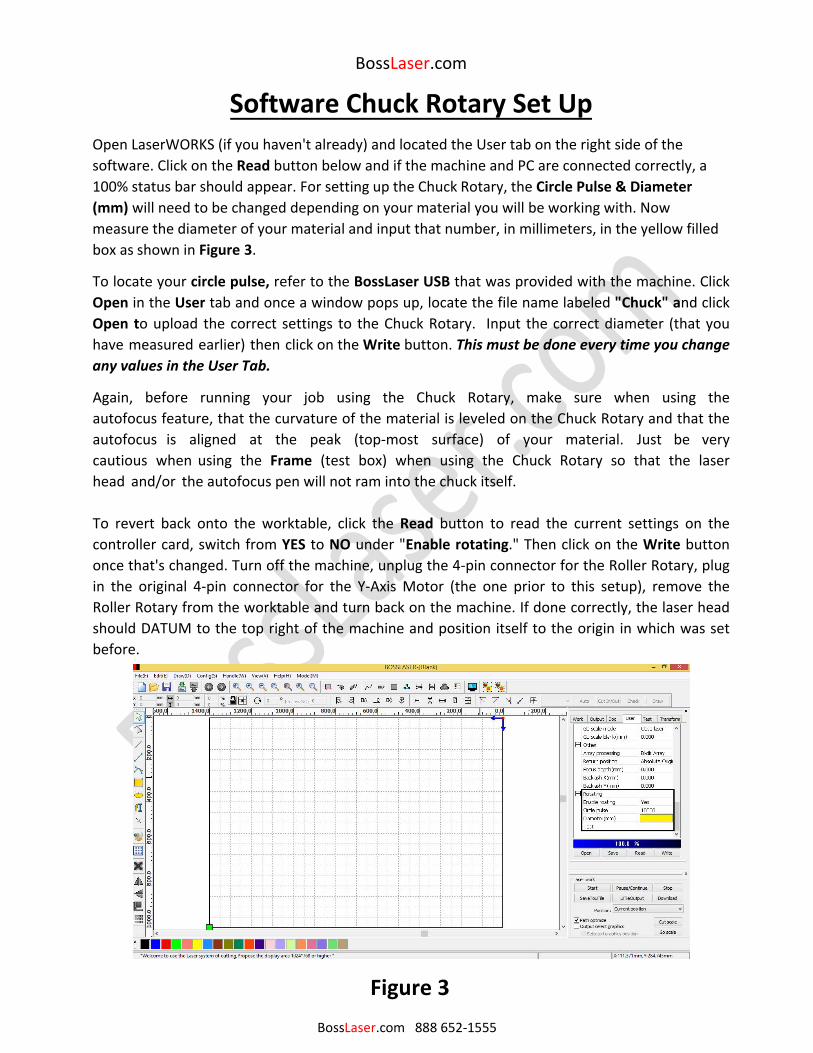
Software Chuck Rotary Set Up Open LaserWORKS (if you haven't already) and located the User tab on the right side of the software. Click on the Read button below and if the machine and PC are connected correctly, a 100% status bar should appear. For setting up the Chuck Rotary, the Circle Pulse & Diameter (mm) will need to be changed depending on your material you will be working with. Nowmeasure the diameter of your material and input that number, in millimeters, in the yellow filledbox as shown in Figure 3.
To locate your circle pulse, refer to the BossLaser USB that was provided with the machine. Click Open in the User tab and once a window pops up, locate the file name labeled "Chuck" and click Open to upload the correct settings to the Chuck Rotary. Input the correct diameter (that you have measured earlier) then click on the Write button. This must be done every time you change any values in the User Tab.
Again, before running your job using the Chuck Rotary, make sure when using the autofocus feature, that the curvature of the material is leveled on the Chuck Rotary and that the autofocus is aligned at the peak (top-most surface) of your material. Just be very cautious when using the Frame (test box) when using the Chuck Rotary so that the laser head and/or the autofocus pen will not ram into the chuck itself.
To revert back onto the worktable, click the Read button to read the current settings on the controller card, switch from YES to NO under "Enable rotating." Then click on the Write button once that's changed. Turn off the machine, unplug the 4-pin connector for the Roller Rotary, plug in the original 4-pin connector for the Y-Axis Motor (the one prior to this setup), remove the Roller Rotary from the worktable and turn back on the machine. If done correctly, the laser head should DATUM to the top right of the machine and position itself to the origin in which was set before.
Figure 3 BossLaser.com 888 652-1555
BossLaser.com 888 652-1555
BossLaser.com
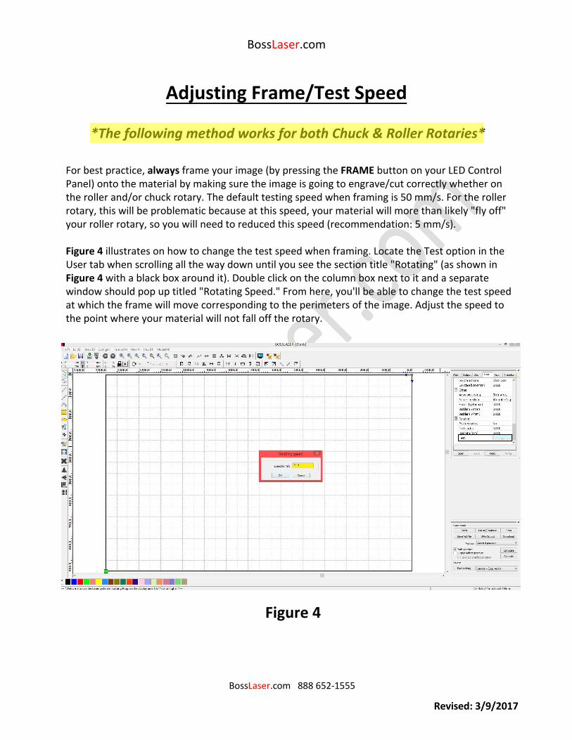
Adjusting Frame/Test Speed
For best practice, always frame your image (by pressing the FRAME button on your LED Control Panel) onto the material by making sure the image is going to engrave/cut correctly whether on the roller and/or chuck rotary. The default testing speed when framing is 50 mm/s. For the roller rotary, this will be problematic because at this speed, your material will more than likely "fly off" your roller rotary, so you will need to reduced this speed (recommendation: 5 mm/s).
Figure 4 illustrates on how to change the test speed when framing. Locate the Test option in the User tab when scrolling all the way down until you see the section title "Rotating" (as shown in Figure 4 with a black box around it). Double click on the column box next to it and a separate window should pop up titled "Rotating Speed." From here, you'll be able to change the test speed at which the frame will move corresponding to the perimeters of the image. Adjust the speed to the point where your material will not fall off the rotary.
Figure 4
*The following method works for both Chuck & Roller Rotaries*
Revised: 3/9/2017