Embed Size (px)
Citation preview
Operator’s Manual
An IKONICS IKNX
Engineered, manufactured and supported in the USA by MediaBlast, Inc. and IKONICS Corporation.
Made in USA
160921

1
NOTE: This machine is equipped with a side mounted dust collector see OMD #D. Care should always be taken when moving the machine to ensure that the machine is always stabilized during machine movement. If
the model includes a front unpainted lifting brace, this brace is a temporary shipping brace only.
QUICK OPERATION GUIDE
The information that follows will be used to get your new CrystalBlast Elite setup and running in the shortest period of time. Use this guide and the Operation & Maintenance Diagram, (OMD), for the initial machine set-up and operation. You may refer to this guide at any time, for more detailed operation instructions refer to the main Operator’s Manual starting on page 7. FIRST
To remove the machine from the pallet if the machine came with a cardboard box, first remove the screws holding the cardboard box to the wooden pallet. Lift the box off over the top of the machine, if you do not have adequate vertical height, cut the box open at one of the corners and remove. Use the pallet to locate the machine as close to the installation location as possible.
Remove the four 3/8” lag-bolts located on the machine leg braces. Remove the unpainted, temporary front leg lift support after the machine has been placed in the final location. Models with machine casters will require installation of the casters by the customer. Two locking and three non-locking wheels are supplied, always position the two locking casters on the front two legs of the machine for greater stability when operating the machine.
Some machines are shipped with strapping over the pressure pot flange for stability. These straps are under extreme tension, use caution and always wear safety glasses and gloves when removing the shipping straps.
Only lift the machine slightly vertically to allow the shipping pallet to be removed.
Using a dolly, take care to stabilize while moving the machine into position.
If this model includes machine casters (optional), install two locking casters on the front legs and the non-locking on the rear, then move the machine into the final location. An additional caster may be supplied on the side stability leg, OMD #R.
After the machine has been placed into position follow the steps listed below:
Remove all items from inside the cabinet. The Foot Pedal Valve is a normally open valve; air will flow through the valve and close the on-off Pneumatic Pinch Valve when the pot is pressurized. Pressing down on the Foot Pedal Valve, OMD #Q, will allow the Pneumatic Pinch Valve, OMD #N, to open and blasting will occur. The air compressor main air supply line requires 90 psi for proper operation of the machine controls; do not allow the main air supply to fall below 90 psi.
If this machine has been shipped with the armrest removed, OMD #Z, install the armrest now using the supplied fasteners. When securely fastened, press the padded rest into the armrest frame.
Open the side access door, OMD #H, and install both lights at this time, make sure the inside slinger washers are installed on the bulb stem prior to bulb installation.
Attach the compressor air supply line to the machine at the Main Air Inlet Valve located at the rear of the cabinet. This machine has been shipped without hose fittings to allow the customer to maintain uniformity by installing matching fittings already in use at their facility, these may include quick-disconnect fittings. Match the air inlet fitting to the size of the Main Air Inlet Valve or use a plumbing reducer bushing if needed. Using coiled air hoses and or multiple quick-connectors is not advised, this may cause compressed air flow problems that may affect proper machine operation. If the machine has been ordered with an ambient dryer, install the dryer first making sure the dryer is installed in the direction of air flow. After dryer installation, install the compressor air supply line.
Release the power cord, 120 volt, and plug into any standard 120 volt 60Hz service outlet. The running amperage of this machine is 1500 watts or 14-15 amps. Any unused service outlet should operate the machine. The use of extension cords is not recommended however, if you have to use an extension cord, make sure the cord amperage is adequate for the machine amperage rating. All extension cords have a printed maximum amperage rating listed on the cord. Never use extension cords rated at an amperage less than 15 amps.
Use at least a 14 gauge cord for extensions exceeding 10 feet.
PLEASE READ THROUGH THIS MANUAL BEFORE OPERATION
MAXIMUM MACHINE INLET PRESSURE 125 PSI MINIMUM LINE PRESSURE 90 PSI
For proper machine operation the above air requirements must be met
NO
SAND
2
NOTE: The machine blast can be stopped at any time by releasing the Foot Pedal Valve. Using the 3 Way Pot
Control Valve, OMD #T, can prevent air from entering the pressure pot and stop the blast in 2 seconds.
Using the machine on-off switch, OMD #B, located on the left side of the light housing turn the dust collector blower and lighting switch to the on position. The second switch is used to turn the LED back inspection lighting on and off for part inspection during part processing.
Use the two adjustment knobs on the foot pedal bracket, OMD #Q, to adjust the height of the pedal for standing or sitting position. With the operator stool next to the machine, align the stool foot rest with the top of the blast pedal. This will allow the operator to rest their foot during pedal operation.
The machine is now almost operational. Make sure the air compressor is operational and the minimum air inlet line pressure is 90 psi. The 3 Way Pot Control Valve OMD #T, must be closed at this time to prevent compressed air from entering the pot assembly. If the pot is pressurized you will not be able to open the pot to allow the abrasive to drop from the hopper into the pressure pot assembly. If your compressor isn’t adequate in volume, the machine may start to blast and not stop when you remove your foot from the blast pedal. The CrystalBlast Elite machine requires 10-15 psi more airline pressure than the machine blasting pressure. Please remember, you can exhaust the pressure pot at any time to stop the machine blasting by using the 3 Way Pot Control Valve, OMD #T.
Open the access door and with the blower running, pour 30-35 pounds of abrasive onto the operator work grate.
The exhaust blower will prevent dust from exiting the machine during this process.
Go to the front of the machine and push in on the Pot Loading Handle, OMD #L. Hold the handle in and allow the abrasive to drop from the machine hopper into the pressure pot. Occasionally release the handle assembly to the closed position, and re-open. This will help fill the pot and move the abrasive into the pot. Not all the abrasive will enter the pot because of the compound angle of adjoining hopper pieces; this is normal and the finer the abrasive the more stacking you may experience. An optional hopper vibrator assembly is available for customer installation, please call and ask for details.
Adjust the Air Regulator using the adjustment knob located on the instrument panel on the left side of the machine at window level, OMD #F. Normal blasting pressures range from 20-40 psi and it may become necessary to set the regulator again during the actual blasting process. The type and length of the air supply line used to connect the compressed air to the machine often creates a pressure drop, flow problem, during machine operation making a final regulator adjustment necessary. The resting pressure, when the blast is off, will be what is required for any blasting pressure based on machine set-up and installation materials.
When the pot has been filled with abrasive, pressurize the pot assembly using the 3 Way Pot Control Valve, OMD #T, located on the instrument panel. See the Main Manual for exact instructions on valve operation.
Stepping down on the Foot Pedal Valve, OMD #Q, will activate the blast. Releasing the Foot Pedal Valve will stop the blast.
ADJUSTING THE ABRASIVE FLOW Adjusting the media flow is simple. Locate the Abrasive Choke Valve, OMD #O, located at the bottom of the pot assembly opposite the Pneumatic Pinch Valve, OMD #N. When the valve is completely open, you will see very little abrasive exiting the nozzle. Never close this valve at any time. Adjust as follows:
Set the Abrasive Choke Valve at 45 degrees and test for blast by pressing down on the Foot Pedal Valve. If very little abrasive is exiting the nozzle after 2-3 seconds, close the Abrasive Choke Valve a small amount by moving the handle about 1/4"-3/8” towards closed position (horizontal to the hose). Just before the nozzle is delivering the proper amount of abrasive, the abrasive flow will pulse slightly. Close the Abrasive Choke Valve a bit more and the pulsing will disappear, the setting is now correct. This setting will stay correct unless you change the blasting pressure or abrasive mesh size. All abrasives will wear during use making the abrasive smaller. This may require a change in the valve setting after hours of machine operation when the abrasive wears to a finer size. Always depressurize the pressure pot assembly, using the 3 Way Pot Control Valve OMD #T, when the air compressor air supply is turned off for the day. The air controls will open when the pressure in the compressor tank falls below 30 psi higher than the machine set blasting pressure.
PPRREESSSSUURREE BBLLAASSTT CCFFMM CCOONNSSUUMMPPTTIIOONN
20 PSI 30 PSI 40 PSI 50 PSI 60 PSI 70 PSI 80 PSI 90 PSI 100 PSI 1/16” 0.062 2.00 2.50 3.10 3.70 4.20 4.80 5.40 5.90 6.50 3/32” 0.094 4.40 5.70 7.00 8.20 9.50 10.80 12.10 13.30 14.60 1/8” (#2) 0.125 7.90 8.38 10.29 12.20 14.02 15.93 17.76 19.67 21.80 3/16” (#3) 0.187 15.00 18.92 23.24 27.39 31.54 35.85 40.08 44.15 49.00 1/4" (#4) 0.250 26.00 33.62 41.17 48.64 56.11 63.66 71.13 78.68 85.00 1/2" (#8) 0.500 105.00 143.46 164.34 195.05 224.93 254.81 284.69 314.57 346.00
Nozzle Size CFM CONSUMPTION AT SPECIFIC PRESSURES
3
Page
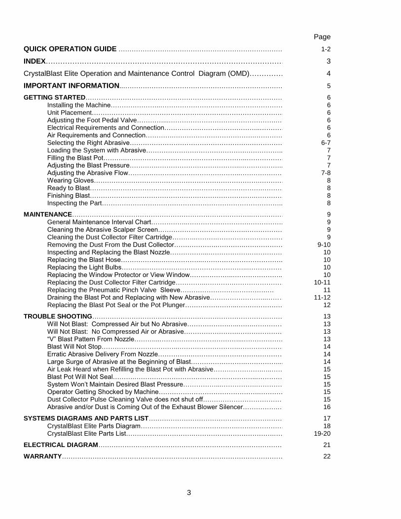
QUICK OPERATION GUIDE …………………………………………………………………… 1-2
INDEX……………………………………………………………………………………… 3
CrystalBlast Elite Operation and Maintenance Control Diagram (OMD)…………………. 4
IMPORTANT INFORMATION..……………………………………………………………….. 5
GETTING STARTED……………………………………………………………………………….. 6 Installing the Machine…………………..………………………………………………… 6 Unit Placement……………………………………………………………………………. 6 Adjusting the Foot Pedal Valve…………...………………………………………….…. 6 Electrical Requirements and Connection……………………………………..………… 6 Air Requirements and Connection………….……………………………….………….. 6 Selecting the Right Abrasive……………………………………………….……………. 6-7 Loading the System with Abrasive……………………………………….…………….. 7 Filling the Blast Pot……….………………………………………………..……………… 7 Adjusting the Blast Pressure………….………………………………..……………….. 7 Adjusting the Abrasive Flow………..…………………………………..………………. 7-8 Wearing Gloves………………………………………………………………….………… 8 Ready to Blast…………………………………………………………………….………. 8 Finishing Blast………………………………………………………………….…………. 8 Inspecting the Part……………………………………………………………………….. 8
MAINTENANCE……………………………………………………………………….…………… 9 General Maintenance Interval Chart……………..……………………….…………….. 9 Cleaning the Abrasive Scalper Screen………………………………….……………… 9 Cleaning the Dust Collector Filter Cartridge………..……….………………………… 9 Removing the Dust From the Dust Collector……………….………….………………. 9-10 Inspecting and Replacing the Blast Nozzle……………...……………….……………. 10 Replacing the Blast Hose……………...………………..………………………………. 10 Replacing the Light Bulbs………..………………………………………..……………… 10 Replacing the Window Protector or View Window………………..………………….. 10 Replacing the Dust Collector Filter Cartridge…………..………….…………………….. 10-11 Replacing the Pneumatic Pinch Valve Sleeve………………………………….… 11 Draining the Blast Pot and Replacing with New Abrasive……………………..…………. 11-12 Replacing the Blast Pot Seal or the Pot Plunger……….…………..………………….. 12
TROUBLE SHOOTING………………………………………………………………………………… 13 Will Not Blast: Compressed Air but No Abrasive……………….…..…….……………… 13 Will Not Blast: No Compressed Air or Abrasive…………………….…………………….. 13 “V” Blast Pattern From Nozzle………...………………………………...………………….. 13 Blast Will Not Stop……………………………..……………………….…………………….. 14 Erratic Abrasive Delivery From Nozzle…………….………………….……………………. 14 Large Surge of Abrasive at the Beginning of Blast…………………….……………........ 14 Air Leak Heard when Refilling the Blast Pot with Abrasive………………….…..………. 15 Blast Pot Will Not Seal……….………………………………………………..……………… 15 System Won’t Maintain Desired Blast Pressure……………...…………….……………… 15 Operator Getting Shocked by Machine……………………………………….……………… 15 Dust Collector Pulse Cleaning Valve does not shut off……………………………… 15 Abrasive and/or Dust is Coming Out of the Exhaust Blower Silencer…………….………. 16
SYSTEMS DIAGRAMS AND PARTS LIST…………………………………………………………. 17 CrystalBlast Elite Parts Diagram………….……….………………….………………………. 18 CrystalBlast Elite Parts List………………………….……………………………….………… 19-20
ELECTRICAL DIAGRAM………………………………………………………………………………… 21
WARRANTY……………………………………………………………………………………………….. 22

4
OPERATION AND MAINTENANCE DIAGRAM (OMD) AA
KEY A. 700 cfm blower assembly
B. Machine On-Off switch and control switch
for On-Off/Dimmer back lighting C. 550 cfm window sweep light housing with
air inlet filter D. Reverse/Pulse dust collector cabinet
chamber E. Air pressure gauge for blasting pressure
F. Air-regulator
G. Dust collector reverse pulse control
button H. Side access door and lockable handle
I. 3/32” tungsten carbide nozzle
J. Micro-Flex abrasive hose
K. Back lighting, LED type, safety glass view
window and protector glass L. Pot Loading Handle
M. ASME coded pressure pot
N. Pneumatic Pinch Valve & micro filter
O. Abrasive Choke Valve
P. Mixing cross
Q. Foot Pedal Valve, Adjustable for ergo
operation R. Stabilizer leg
S. Dust collector drain cap
T. 3 Way Pot Control Valve
U. Pot Access Port & Cover for cleanout
V. Operator ports
W. Blow-off gun
X. Adjustable leg pad, optional castor
Y. Small pot drain
Z. Padded ergo armrest
AA.Air Filter / Watertrap
BB.Main air inlet shut off valve
NO
SAND
CrystalBlast Elite
A B
C
D E
F
G
H
I J
K
N
X
Z
L
M
O
Y P
Q
R
S
T
U
V
W
BB

5
IMPORTANT INFORMATION Welcome to the CrystalBlast Family! You have just purchased the Elite sandcarving cabinet. This machine is designed, manufactured and assembled in the USA by Media Blast & Abrasive Inc. Established in 1977 and building fine abrasive blasting equipment for almost 40 years. The CrystalBlast Elite is very easy to operate and maintain. However, there are several important issues of which you should be aware of:
ALWAYS USE CLEAN, DRY COMPRESSED AIR. Moisture will cause abrasive to stick together preventing flow. Your CrystalBlast Elite is equipped with a reverse pulse cleaning filter cartridge dust collection system. Please review the compressed air requirements prior to operating this machine and install an ambient air dryer per location shown on pneumatic diagram, if hot air or moist air is entering the cabinet.
FOR PROPER OPERATION, THE STANDARD 3/32” i.d. NOZZLE REQUIRES 5.7 CFM OF COMPRESSED AIR (@ 30 psi). Make sure that your air compressor exceeds this requirement by at least 75% otherwise, your blast pressure may not reach the 90 psi required to operate the air contorls. Premature compressor failure can be a secondary result of using a marginally sized air compressor. The optional 1/8” i.d. nozzle requires 8.38 cfm @ 30 psi. The 3/32” nozzle is recommended for operation using 9-10 cfm compressor volume and the 1/8” nozzle is recommended for operation using 14-16 cfm compressor air volume. Always look at compressor cfm volume at 90-100 psi not 0 psi displacement.
DO NOT BLAST ABOVE 60 PSI. This machine is designed for operation at low pressures. Blasting at pressures in excess of 60 psi will lead to premature breakdown of the abrasive and premature failure of wear components (blast hose, blast nozzles, window protector etc.). The Elite model includes the high pressure long wear abrasvie control features but, an upgraded boron carbide nozzle is available for 8-10 times extension of nozzle life.
ALWAYS DEPRESSURIZE THE POT AT THE END OF THE DAY. It is necessary to depressurize the pot prior to turning off the air compressor. Otherwise, the nozzle will begin blasting once the line pressure drops to regulator blasting pressure. Furthermore, the next time that the air compressor is turned on, the system will immediately begin blasting until the air compressor builds up adaquate air pressure for proper air control operation. When the compressor is shut down always de-pressurize the machine pressure pot assembly.
REGULARLY CHECK THE BORE OF THE NOZZLE. It is important to replace the nozzle after it has worn 1/32”. Not only will the worn nozzle use more compressed air, but the abrasive will impact the part more aggressively and increase the potential for damaging the masking material. As the volume of air and abrasive increases, it will create additional wear on the blast hose. Always depressurize the pressure pot during any machine maintenance.
A CLEAN DUST COLLECTOR WILL KEEP THE CABINET VISIBILITY CLEAR. Cleaning the dust collector is key to maintaining optimum cabinet visibility. Use the pulse cleaning button located on the instrument panel to clean the dust collector filter cartridge. Empty the dust storage hopper on an established schedule based on the machine usage time. Push the pulse cleaning button 2-3 times after processing each part.
USE MBA REPLACEMENT COMPONENTS. Replacement of worn components with non MBA parts will void the machine warranty. The components used by Media Blast are of the highest quality and will provide the longest serviceable life.
REVIEW THE TROUBLESHOOTING GUIDE AND FOLLOW THE INSTRUCTIONS PRIOR TO CALLING MBA FOR TROUBLESHOOTING ASSISTANCE. Most problems associated with this machine can be identified by simply consulting the Troubleshooting Guide. However, if your problem cannot be found in the Troubleshooting Guide, please give us a call. Nearly all equipment malfunction issues can be resolved over the telephone.
NEVER OVERFILL THE PRESSURE POT: The CrystalBlast Elite is equipped with Quick Pot Loading 3-way circuit. Overfilling the 30 to 35 pound abrasive charge will result in poor abrasive delivery and abrasive flow control adjustment.
NEVER DE-PRESSURIZE THE POT USING THE 3-WAY CIRCUIT REPEATITLY WITHOUT BLASTING FIRST!

6
GETTING STARTED OPERATOR’S MANUAL STARTS HERE UNIT PLACEMENT: Allow adequate clearance for loading and unloading the blast cabinet. MBA recommends 36” in
front of the cabinet for the operator and 36”on the door sides of the cabinet. The Elite includes one side access door and a side mounted dust collector. Always leave at least 9” of clearance on the dust collector side of the cabinet to facilitate airflow from the exhaust of the dust collector. More room is required when servicing the dust collector and moving the machine to service it may be required. Never place the unit where direct light can strike the operator view window. This will cause reflections on the view window and make it uncomfortable and difficult for the operator to view the work in progress.
VERTICAL PLACEMENT OF FOOT PEDAL VALVE: The Elite includes a vertically adjustable Foot Pedal Valve assembly, OMD #Q. This allows for adjustment of the pedal for use with any customer supplied chair/stool. Position the pedal to allow the operator’s foot to rest on the chair/stool support making operation of the pedal effortless. Remove the adjustment knobs to raise and lower the pedal support. Lower the pedal for standing machine operation.
ELECTRICAL REQUIREMENTS AND CONNECTION: All CrystalBlast sandcarving cabinets are wired standard for
120V single phase service. MBA recommends that this cabinet be installed on a dedicated 20-amp breaker similar to any large single power-consuming appliance.
AIR REQUIREMENTS AND CONNECTION: The standard 3/32” i.d. nozzle requires 5.7 cfm @ 30 psi. The optional 1/8” i.d. nozzle requires 8.38 cfm @ 30 psi. Note: cfm – volume of compressed air in cubic feet per minute, psi – pressure of air in pounds per square inch. Stopping the blast during machine operation will save on compressed air (e.g., blasting 50 seconds of every minute will decrease the compressed air requirements by 16%. Make sure that your air compressor exceeds this requirement by at least 75% (9-10 cfm for the 3/32” nozzle and 14-16 cfm for the 1/8” nozzle). Premature compressor failure can be a secondary result of using a marginally sized air compressor. Note: The system must provide at least 10-15 psi more line pressure to the cabinet than the actual blast pressure. MBA recommends a two-stage air compressor but any air compressor capable of 9-10 cfm at 90-100 psi will be adequate for proper machine operation using the 3/32” nozzle. When using a two stage air compressor, set the maximum line inlet pressure at no more than 125 psi. This may require installation of a master compressor air regulator; if unclear call the factory for information. It is very important that the compressed air be clean and dry. Wet compressed air will cause the abrasive to bond together and stop flowing. Under sizing the air compressor, will create a situation that will not allow adequate time for the compressed air to cool in the air receiver tank. This warm compressed air enters the blast cabinet and immediately cools as the pressure drops. The resulting condensation will cause the abrasive to stick together. If wet compressed air is suspected, install an air dryer prior to the air entering the blast cabinet (MBA Ambient Air Dryer, P/N 100-03-003). Note: As the blast nozzle wears, the air requirements for the system will increase. If the air compressor is not capable of handling the higher air volumes, the blast pressure will begin to decrease and loss of line pressure will lead to poor machine performance. Minimum air hose supply line size must be at least 1/4” ID but, 3/8” ID is recommended. Connect to the machine using quick disconnect sleeve couplers. The Elite model includes a Main Air Inlet Valve on the back rear leg to control air On/Off.
SELECTING THE RIGHT ABRASIVE: There are three different basic types of abrasives that can be effectively used
for etching and carving on glass; brown aluminum oxide, white aluminum oxide and black silicon carbide. Each type has its own beneficial qualities:
Brown Aluminum Oxide – Some manufacturers recommend and sell this abrasive. This abrasive is more forgiving than silicon carbide because it is not as aggressive. It normally has more dust than silicon carbide and it cuts glass slower than silicon carbide. For industrial applications, it is the most commonly used abrasive for surface preparation for coatings. However, the productivity of aluminum oxide is significantly slower than silicon carbide and as the abrasive is used, the abrasive particles become more rounded which continues to reduce the effectiveness of the etch. Aluminum oxide is a good abrasive to use when sandcarving for the first time.
White Aluminum Oxide - White aluminum oxide differs from brown aluminum oxide because it has no iron content. This means that the abrasive will not leave a stain on the part that is blasted. Since the abrasive is screened to tighter specifications, it may be less dusty than brown aluminum oxide. Both white and brown aluminum oxides are more forgiving on the mask material. MBA recommends that aluminum oxide be used by beginners and less experienced operators.
7
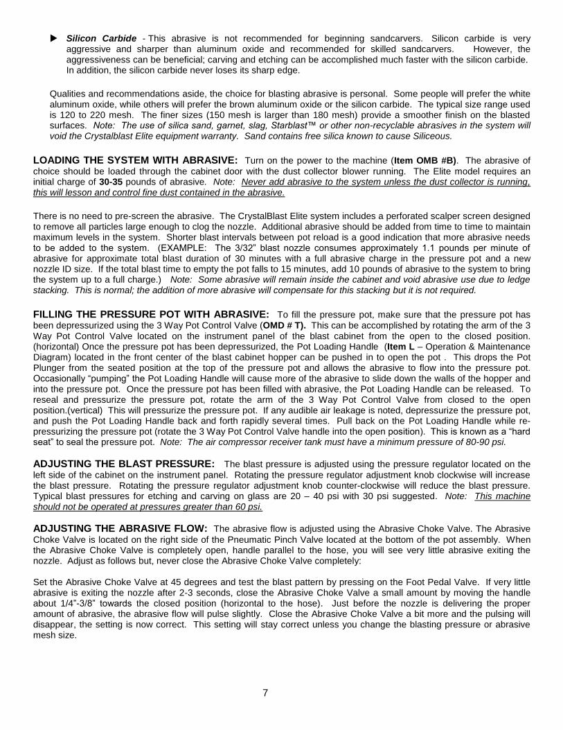
Silicon Carbide - This abrasive is not recommended for beginning sandcarvers. Silicon carbide is very aggressive and sharper than aluminum oxide and recommended for skilled sandcarvers. However, the aggressiveness can be beneficial; carving and etching can be accomplished much faster with the silicon carbide. In addition, the silicon carbide never loses its sharp edge.
Qualities and recommendations aside, the choice for blasting abrasive is personal. Some people will prefer the white aluminum oxide, while others will prefer the brown aluminum oxide or the silicon carbide. The typical size range used is 120 to 220 mesh. The finer sizes (150 mesh is larger than 180 mesh) provide a smoother finish on the blasted surfaces. Note: The use of silica sand, garnet, slag, Starblast™ or other non-recyclable abrasives in the system will void the Crystalblast Elite equipment warranty. Sand contains free silica known to cause Siliceous.
LOADING THE SYSTEM WITH ABRASIVE: Turn on the power to the machine (Item OMB #B). The abrasive of
choice should be loaded through the cabinet door with the dust collector blower running. The Elite model requires an initial charge of 30-35 pounds of abrasive. Note: Never add abrasive to the system unless the dust collector is running, this will lesson and control fine dust contained in the abrasive.
There is no need to pre-screen the abrasive. The CrystalBlast Elite system includes a perforated scalper screen designed to remove all particles large enough to clog the nozzle. Additional abrasive should be added from time to time to maintain maximum levels in the system. Shorter blast intervals between pot reload is a good indication that more abrasive needs to be added to the system. (EXAMPLE: The 3/32” blast nozzle consumes approximately 1.1 pounds per minute of abrasive for approximate total blast duration of 30 minutes with a full abrasive charge in the pressure pot and a new nozzle ID size. If the total blast time to empty the pot falls to 15 minutes, add 10 pounds of abrasive to the system to bring the system up to a full charge.) Note: Some abrasive will remain inside the cabinet and void abrasive use due to ledge stacking. This is normal; the addition of more abrasive will compensate for this stacking but it is not required.
FILLING THE PRESSURE POT WITH ABRASIVE: To fill the pressure pot, make sure that the pressure pot has been depressurized using the 3 Way Pot Control Valve (OMD # T). This can be accomplished by rotating the arm of the 3 Way Pot Control Valve located on the instrument panel of the blast cabinet from the open to the closed position. (horizontal) Once the pressure pot has been depressurized, the Pot Loading Handle (Item L – Operation & Maintenance Diagram) located in the front center of the blast cabinet hopper can be pushed in to open the pot . This drops the Pot Plunger from the seated position at the top of the pressure pot and allows the abrasive to flow into the pressure pot. Occasionally “pumping” the Pot Loading Handle will cause more of the abrasive to slide down the walls of the hopper and into the pressure pot. Once the pressure pot has been filled with abrasive, the Pot Loading Handle can be released. To reseal and pressurize the pressure pot, rotate the arm of the 3 Way Pot Control Valve from closed to the open position.(vertical) This will pressurize the pressure pot. If any audible air leakage is noted, depressurize the pressure pot, and push the Pot Loading Handle back and forth rapidly several times. Pull back on the Pot Loading Handle while re-pressurizing the pressure pot (rotate the 3 Way Pot Control Valve handle into the open position). This is known as a “hard seat” to seal the pressure pot. Note: The air compressor receiver tank must have a minimum pressure of 80-90 psi.
ADJUSTING THE BLAST PRESSURE: The blast pressure is adjusted using the pressure regulator located on the
left side of the cabinet on the instrument panel. Rotating the pressure regulator adjustment knob clockwise will increase the blast pressure. Rotating the pressure regulator adjustment knob counter-clockwise will reduce the blast pressure. Typical blast pressures for etching and carving on glass are 20 – 40 psi with 30 psi suggested. Note: This machine should not be operated at pressures greater than 60 psi.
ADJUSTING THE ABRASIVE FLOW: The abrasive flow is adjusted using the Abrasive Choke Valve. The Abrasive
Choke Valve is located on the right side of the Pneumatic Pinch Valve located at the bottom of the pot assembly. When the Abrasive Choke Valve is completely open, handle parallel to the hose, you will see very little abrasive exiting the nozzle. Adjust as follows but, never close the Abrasive Choke Valve completely: Set the Abrasive Choke Valve at 45 degrees and test the blast pattern by pressing on the Foot Pedal Valve. If very little abrasive is exiting the nozzle after 2-3 seconds, close the Abrasive Choke Valve a small amount by moving the handle about 1/4”-3/8” towards the closed position (horizontal to the hose). Just before the nozzle is delivering the proper amount of abrasive, the abrasive flow will pulse slightly. Close the Abrasive Choke Valve a bit more and the pulsing will disappear, the setting is now correct. This setting will stay correct unless you change the blasting pressure or abrasive mesh size.

8
Always shut off the Main Air Inlet Valve and depressurize the pressure pot at the end of daily operation or when the air compressor will be turned off. Depressurize the pressure pot when the air compressor is going to be turned off for the day using the 3 Way Pot Control Valve, OMD # T. Always remember to have the machine blower running to prevent abrasive escape during pressure pot depressurization.
WEARING GLOVES: The CrystalBlast Elite sandcarving cabinet is equipped with open end velocity gauntlets (or
sleeves) and a box of disposable latex gloves. This gives the operator the choice of blasting with or without gloves. Abrasives can cause irritation or damage to the skin if accidentally exposed to the blast. MBA recommends that the operator wear gloves while blasting. Latex or Nitrile gloves offer the highest degree of fingertip sensitivity while offering a comfortable degree of protection. All CrystalBlast Elite models are available with attached gloves upon customer request.
READY TO BLAST: The unit is now ready for blasting. Turn on the electrical on-off switch (Item B– Operation &
Maintenance Diagram). Place a piece of scrap glass in the machine to test the blast. Using a pair of disposable gloves, place both arms in the arm ports and pick up the piece of glass for the test. Rest your elbows on the padded arm rest and hold the nozzle/nozzle holder like a pencil about 3-4 inches from the part surface. Always remember to start the blasting, off of the part surface. Depress the Foot Pedal Valve and begin blasting the test part. Note: Never point the nozzle at the window. The abrasive will permanently frost the protector window. Note: The MBA CrystalBlast Elite system may provide different results than other blast systems. When the unit is first operated, use scrap glass to become familiar with the nozzle pattern and speed. Place masking material on the scrap glass to see how long the mask material will stand up to the blast. The experienced operator may find that the CrystalBlast Elite system will be operated at lower blast pressures than previously experienced with other systems.
FINISHING BLAST: At the end of the day, when the blasting is finished or when the air compressor is turned off, the
pressure pot must be depressurized. Use the 3 Way Pot Control Valve, and move the handle to the closed position (horizontal) allowing the pressure pot to depressurize.
INSPECTING THE PART: The Elite model includes an LED back lighting assembly, OMD # K. This makes part
inspection possible during part processing. The LED lights can be turned on and off using the selector switch located next to the machine on-off control switch, OMD # B. The LED lighting also includes a dimmer switch so you can also change the intensity of the inspection lights.
IMPORTANT NOTE ABOUT FILLING THE PRESSURE POT AND OVERFILLING THE PRESSURE POT
The CrystalBlast Elite is equipped with quick-fill 3-way valve circuit. This circuit allows fast de-pressurization of the pressure pot assembly for pot loading. Overfilling the pressure pot can result in poor abrasive delivery performance, irregular abrasive delivery or no abrasive delivery. This is caused when the abrasive volume inside the pressure pot is filled to overcapacity.
Never fill the Elite pressure pot with more than 35 pounds of abrasive. Never de-pressurize the pressure pot more than once without blasting for 2 to 3 seconds. The 3-way valve circuit, during pot depressurization, pushes a small about of abrasive into the choke valve air delivery hose. This abrasive will be cleared during the first few seconds of blasting after any pot reload. Constant repeated de-pressurization of the pressure pot without blasting for a few seconds and or overfilling the pot beyond recommended abrasive volume can plug the choke valve compressed air supply hose.
WHAT TO DO IF THE CHOKE VALVE AIR SUPPLY HOSE HAS BEEN PLUGGED? 1. Remove the compressed air supply from the machine 2. De-pressurize the pressure pot making sure the pot valve can be opened indicating the compressed air has been
removed from the pressure pot. 3. With the compressed air supply removed from the machine and the pressure pot de-pressurized remove the
compressed air supply hose on the inlet side of the choke valve and remove any and all abrasive visible inside the hose.
4. At this time remove the abrasive supply hose exiting the silver pinch valve on the opposite side of the pressure pot outlet and also remove any visible abrasive from inside the hose.
a. Removal of the two hoses is accomplished by pushing in on the small separate ring where the hose enters the choke valve air inlet fitting and the abrasive hose outlet fitting of the pinch valve. While pushing in on the small ring twist and pull on the hose and it will exit the fitting. (see replacement of the blast hose on page 10 for visual instructions.
5. Install the choke valve air supply hose and the abrasive supply hose exiting the pinch valve making sure to insert the hose into the fitting until it seats, about 1/4” to 3/8”. Check the hose installation by trying to pull back and remove the hose after releasing the floating ring.
6. Install the air supply line to the machine, pressurize the pot and start blasting.
NO
SAND

9
MAINTENANCE:
GENERAL EQUIPMENT MAINTENANCE
(Intervals May Vary Depending on Equipment Usage)
DA
ILY
We
ek
ly
MO
NT
HL
Y
SE
MI-
AN
NU
AL
LY
AN
NU
AL
LY
DRAIN REGULATOR WATER TRAP X
CLEAN THE DUST COLLECTOR FILTER CARTRIDGE
X
CLEAN THE ABRASIVE SCALPER SCREEN
X
REMOVE DUST FROM DUST COLLECTOR X
INSPECT THE BLAST NOZZLE X
INSPECT THE BLAST HOSE X
REPLACE THE AIR INLET FILTERS X
REPLACE THE FILTER CARTRIDGE
X
CLEANING THE ABRASIVE SCALPER SCREEN: Lift up the expanded metal work grate and remove the grate
from the cabinet. Use a shop vacuum to clean the debris off of the scalper screen. Replace the operator work grate.
CLEANING THE DUST COLLECTOR CARTRIDGE FILTER: The dust collector cartridge filter should be pulsed to
clean it after each part has been processed with the blower running. To clean the filter, make sure that the machine is operating (lights and dust collector exhaust blower on). Momentarily depress the white button (Item G – Operation & Maintenance Diagram) located on the machine instrument panel on the left of the view window. This button releases a burst of compressed air to clean the cartridge filter from the inside out. Wait 5 seconds, and then pulse clean the filter again. Note: Cleaning the filter 3-4 pulses prior to operating the machine with the blower off is also recommended. Oftentimes, compressed air has small traces of moisture present (especially if the compressor is operated without an air dryer).
REMOVING THE DUST FROM THE DUST COLLECTOR: Periodically, the dust must be removed from the dust
collector hopper. MBA recommends removing the dust at least once per week (more often depending on the type of abrasive used, the blasting pressures and the number of hours per week the machine is in use). Prior to removing the dust, perform the Cleaning the Dust Collector Filters procedure. When the filter cleaning has been completed, the dust collector is ready for dust removal.
Unscrew the dust collector hopper drain cap (Item S – Operation and Maintenance Diagram) but do not remove. With one hand, hold the neck of a plastic bag on the pipe nipple above the hopper drain cap (or use a garbage bag with tie straps and tie it to the pipe nipple). With the other hand, grasp the drain cap through one corner of the bottom of the plastic bag. Finish unscrewing the drain cap and move it aside to allow the dust to drain into the bag. Continue to hold

10
the cap through the plastic bag until all of the dust has been drained. Screw the drain cap back on the nipple. Grasp the neck of the plastic bag below the drain cap and remove the bag. The dust should be contained completely in the bag for disposal without exposing the surrounding area or the operator to the dust.
INSPECTING AND REPLACING THE BLAST NOZZLE: It is important to replace the nozzle after it has worn
1/32”. Not only will the worn nozzle use more compressed air, but the abrasive will impact the part more aggressively. As the volume of air and abrasive increases, it will create additional wear on the blast hose too. The easiest way to know if your nozzle requires replacement is to keep a 1/8” drill bit nearby (or a 5/32” drill bit if the CrystalBlast Elite was purchased with a 1/8” nozzle). If the drill bit fits into the blast nozzle, then it is time to replace the nozzle. Replacement is not manditory but, a worn nozzle uses more compressed air and if the air compressor is margional the machine controls will not operate properly unless 90 psi line pressure is maintained. Always depressurize the pressure pot during any machine maintenance; To replace the blast nozzle, hold the nozzle and nozzle holder in your right hand and the blast hose in your left hand. With your right thumb and forefinger, press the end ring of the nozzle holder toward the nozzle (see diagram below). As you are pressing, pull the abrasive blast hose the other direction using a twisting motion. The hose should release from the nozzle holder. Note: Do not try to remove the nozzle from the nozzle holder. The nozzle holder is designed to be an integral part of the nozzle. Removal and reinstallation of the nozzle in the nozzle holder may cause the nozzle to become a projectile. Injury may occur as a result. Dispose of the nozzle holder with the nozzle when the nozzle has worn out.
REPLACING THE BLAST HOSE: Always depressurize the pressure pot during any machine maintenance,
OMD #T; To replace the blast hose, hold the nozzle and nozzle holder in your right hand and the blast hose in your left hand. With your right thumb and forefinger, press the end ring of the nozzle holder toward the nozzle (see diagram). As you are pressing, pull the abrasive blast hose the opposite direction. Remove the other end of the hose from the connector using the same process. Note: All hoses and tubing are removed using this same procedure. Replace with new abrasive hose in reverse of the above procedure.
REPLACING THE LIGHT BULBS: Replace the light bulbs by opening the cabinet door and unscrewing the spot light,
(s), make sure to replace the cabinet heat resistant sealing washer. New washers are available as a spare part. These washers are a special material for usage on halogen spot lighting. Never use standard washers that may pose a possible fire hazard. Never replace a hot bulb and always wear safety gloves for hand protection. Newer models use a single LED floodlight assembly mounted on the outside top of the cabinet.
REPLACING THE WINDOW PROTECTOR OR VIEW WINDOW: Remove the tightening knobs located on the top
window bracket. Next, loosen the bottom knobs but do not remove the bottom knobs from the window bracket. The bottom bracket will hold the window and window protector during replacement of the protector window. Remove the operator view window, clean and set aside. Next remove the window protector glass. Replace with a new clean protector glass and replace the operator view window. Install the top window bracket and hand tighten the fasteners. Center the window top to bottom before final tightening. Tighten the bottom and top fasteners in a circular motion but make sure not to over-tighten the fasteners.
REPLACING THE DUST COLLECTOR CARTRIDGE FILTER: Prior to replacing the cartridge filter, pulse clean
the dust collector with the power to the machine on. Pulse the filter several times (pause about 5 seconds between pulses) this is to ensure the filter has been sufficiently cleaned. Turn off the power to the machine. Remove the dust from the dust collector hopper first. (Please refer to the REMOVING THE DUST FROM THE DUST COLLECTOR procedure on page 11). Once the dust has been removed and the cap placed back on the hopper, use any clamp to hold the hopper and body together then carefully remove all four hopper holding bolts from the dust collector hopper. When all four bolts have been removed, the hopper can be removed from the cabinet body. It may be necessary to use a putty knife to break the seal.
Hose
Depress End Ring
Nozzle Nozzle Holder
11
Unscrew the large knob underneath the dust collector filter to loosen the holding bracket. Once the filter is loose, lift up on the filter and rotate the filter bracket (attached to the knob) 45°. Slowly drop the filter and bracket out through the bottom of the dust collector body. Insert the new filter inside the dust collector body using caution to not hit the edges of the f ilter against any metal edges. Fit the top of the filter over the guide flange. While holding the filter in position, insert the bracket under the filter making sure the bottom sealing rubber washer is installed. Rest the ends of the bracket on the bottom flange of the dust collector body. Screw the knob on tight making sure that the guide pin is centered in the hole located on the bottom of the cartridge filter. Note: Make sure that the rubber washer is affixed to the guide pin prior to tightening the filter. Dust will escape into the work area if the rubber washer is not in place.
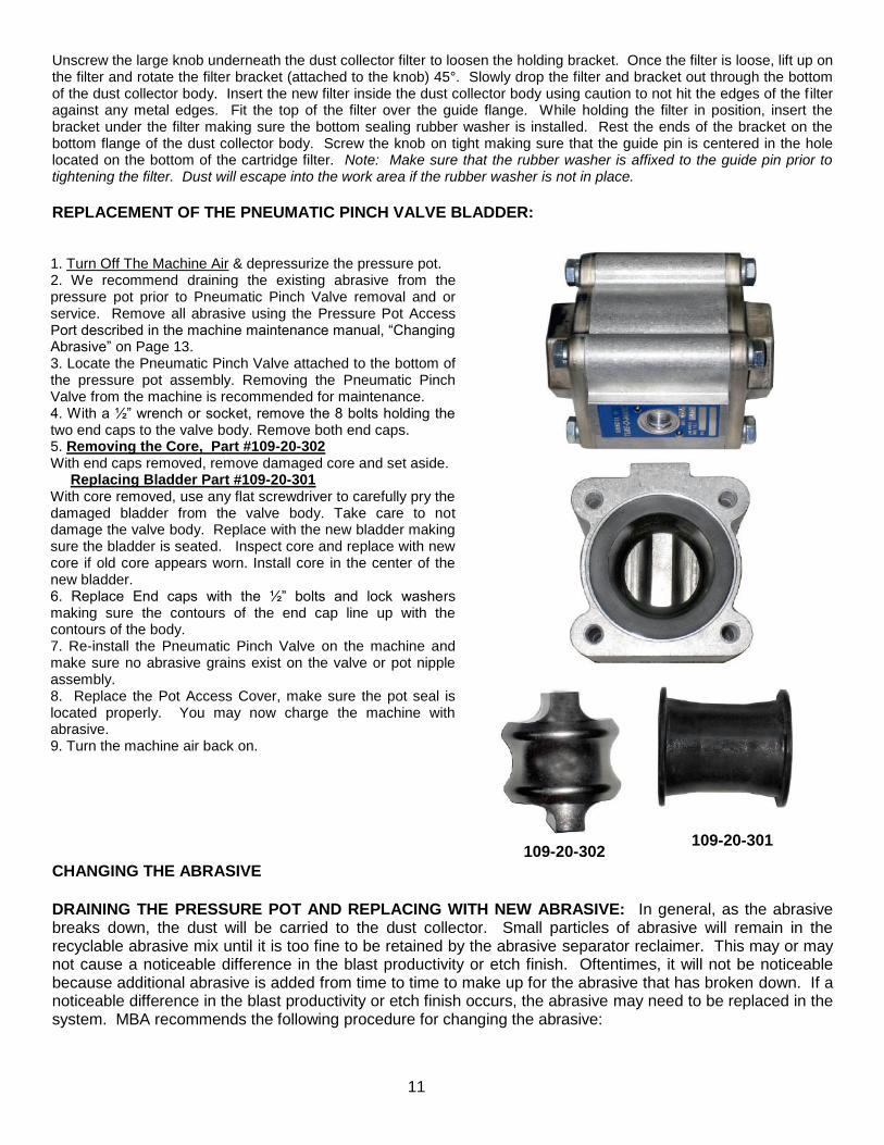
REPLACEMENT OF THE PNEUMATIC PINCH VALVE BLADDER:
CHANGING THE ABRASIVE
DRAINING THE PRESSURE POT AND REPLACING WITH NEW ABRASIVE: In general, as the abrasive breaks down, the dust will be carried to the dust collector. Small particles of abrasive will remain in the recyclable abrasive mix until it is too fine to be retained by the abrasive separator reclaimer. This may or may not cause a noticeable difference in the blast productivity or etch finish. Oftentimes, it will not be noticeable because additional abrasive is added from time to time to make up for the abrasive that has broken down. If a noticeable difference in the blast productivity or etch finish occurs, the abrasive may need to be replaced in the system. MBA recommends the following procedure for changing the abrasive:
1. Turn Off The Machine Air & depressurize the pressure pot. 2. We recommend draining the existing abrasive from the pressure pot prior to Pneumatic Pinch Valve removal and or service. Remove all abrasive using the Pressure Pot Access Port described in the machine maintenance manual, “Changing Abrasive” on Page 13. 3. Locate the Pneumatic Pinch Valve attached to the bottom of the pressure pot assembly. Removing the Pneumatic Pinch Valve from the machine is recommended for maintenance. 4. With a ½” wrench or socket, remove the 8 bolts holding the two end caps to the valve body. Remove both end caps. 5. Removing the Core, Part #109-20-302 With end caps removed, remove damaged core and set aside. Replacing Bladder Part #109-20-301 With core removed, use any flat screwdriver to carefully pry the damaged bladder from the valve body. Take care to not damage the valve body. Replace with the new bladder making sure the bladder is seated. Inspect core and replace with new core if old core appears worn. Install core in the center of the new bladder. 6. Replace End caps with the ½” bolts and lock washers making sure the contours of the end cap line up with the contours of the body. 7. Re-install the Pneumatic Pinch Valve on the machine and make sure no abrasive grains exist on the valve or pot nipple assembly. 8. Replace the Pot Access Cover, make sure the pot seal is located properly. You may now charge the machine with abrasive. 9. Turn the machine air back on.
109-20-302 109-20-301

12
1. Make sure that the lights and exhaust blower are running on the machine. 2. Depressurize the pressure pot using the 3 Way Pot Control Valve. 3. Push in on the Pot Loading Handle to make sure there is no pot pressure; if the valve opens the pot has no air
inside. 4. Place a pan underneath the pressure pot. 5. Remove the Pot Access Cover nut and crab bracket 6. Taking care to remove the port gasket, push the Pot Plunger inside the pot, reverse the port stud and back the pot
cover out of the port access hole with the stud exiting last. 7. Most of the abrasive can now be removed by simply using your hand to scoop the abrasive into the pan
underneath the pot. You can also use a shop vacuum to help clean any remaining abrasive from inside the pot. 8. Remove the drain plug located on the Mixing Cross fitting beneath the pressure pot. Any abrasive remaining will
begin draining into the pan. 9. Remove the expanded metal workgrate from the cabinet. 10. Using a wide putty knife, move all the abrasive from the hopper corners and the ledges to the perforated scalper
screen, the abrasive will drain into the pressure pot. Note: To ensure that no residual abrasive is left in the pressure pot, the pressure pot can be tapped with a rubber mallet to dislodge any trapped abrasive. To ensure nearly complete evacuation of abrasive, always remove the Pot Access Cover on the blast pot and use a shop vacuum to clean any residual abrasive out of the pressure pot and the inside of the scalper screen.
11. Replace and tighten the plug in the Mixing Cross fitting. 12. Replace the Pot Access Cover and make sure the gasket is seated correctly. 13. Install the Pot Access Cover crab bracket and nut and tighten. 14. Replace the expanded metal workgrate. 15. Add 30-35 pounds of new abrasive to the system.
REPLACING THE PRESSURE POT SEAL OR THE POT PLUNGER: This maintenance procedure will unlikely
be performed for many years however, eventually the pressure pot seal will wear out requiring replacement.
1. Turn the machine on. 2. Turn off the Main Air Inlet Valve and depressurize the pressure pot using the 3-Way Pot Control Valve. 3. Place a pan under the pressure pot to catch any abrasive that comes out. 4. Remove the expanded metal workgrate from the cabinet. 5. Locate the clevis attached to the vertical rod that is attached to the Pot Plunger. Remove the cotter pin from
the clevis pin. 6. Pull the clevis pin to disconnect the assembly from the Pot Plunger/rod/clevis. 7. Unthread the clevis from the rod; the Pot Plunger should drop down inside the pressure pot. 8. Remove the Pot Access Cover on the pressure pot by removing the nut that holds the crab bracket in place.
Once the nut and crab have been removed, the Pot Access Cover can be manipulated out of the pressure pot.
9. Unthread the pipe riser inside the pot that guides the Pot Plunger up and down, do not over tighten this nipple when replacing.
10. Remove the pipe riser and Pot Plunger at the same time. 11. Locate the donut shaped pot seal on the abrasive inlet to the pressure pot. 12. Wedge a small screwdriver between the metal lip of the pressure pot and the pressure pot seal. Pry the
pressure pot seal out of the pressure pot, note location of the seal bevel. 13. Install the new pressure pot seal, make sure the bevel is located at the bottom. 14. Replace the Pot Plunger and pipe riser together as a single assembly. The parts must be assembled
together before putting them inside the pressure pot and the pipe riser threaded into place. Install the Pot Plunger with care; make sure the clevis rod passes through the hole in the scalper screen. Use caution and make sure to install the polyethylene seal washer on the clevis rod.
15. Reinstall the Pot Access Cover on the pressure pot. When replacing the Pot Access Cover, make sure that the rubber gasket and Pot Access Cover are uniformly aligned across the access hole. Tighten the nut and crab bracket that holds the Pot Access Cover in place.
16. Thread the clevis back onto the Pot Plunger rod and tighten. 17. Attach the assembly to the clevis with the clevis pin. 18. Reattach the cotter pin to the clevis pin. 19. Check the operation of the Pot Plunger by pushing and pulling the Pot Loading Handle several times. 20. Re-pressurize and depressurize the pressure pot several times. Be sure to pull slightly on the handle each
time the pressure pot is pressurized and push the handle to drop the Pot Plunger each time the pressure pot is depressurized. Reinstall the expanded metal workgrate.
13
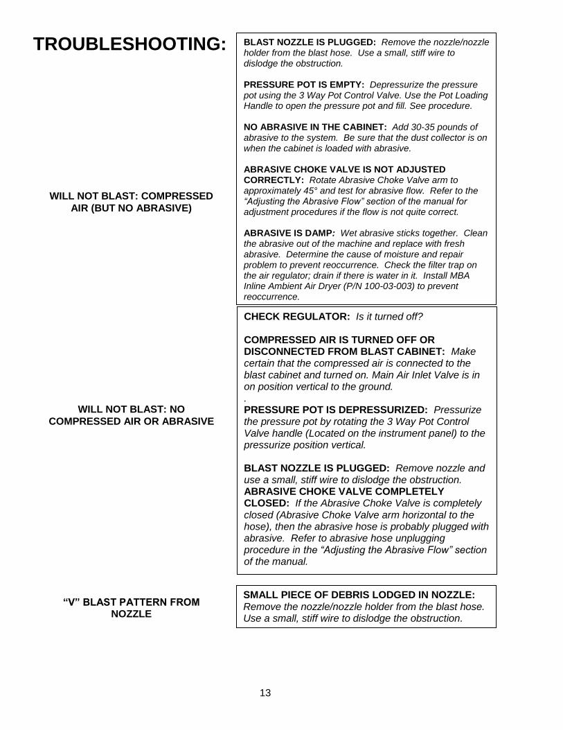
TROUBLESHOOTING:
WILL NOT BLAST: COMPRESSED
AIR (BUT NO ABRASIVE)
WILL NOT BLAST: NO
COMPRESSED AIR OR ABRASIVE
BLAST NOZZLE IS PLUGGED: Remove the nozzle/nozzle holder from the blast hose. Use a small, stiff wire to dislodge the obstruction. PRESSURE POT IS EMPTY: Depressurize the pressure pot using the 3 Way Pot Control Valve. Use the Pot Loading Handle to open the pressure pot and fill. See procedure. NO ABRASIVE IN THE CABINET: Add 30-35 pounds of abrasive to the system. Be sure that the dust collector is on when the cabinet is loaded with abrasive. ABRASIVE CHOKE VALVE IS NOT ADJUSTED CORRECTLY: Rotate Abrasive Choke Valve arm to approximately 45° and test for abrasive flow. Refer to the “Adjusting the Abrasive Flow” section of the manual for adjustment procedures if the flow is not quite correct. ABRASIVE IS DAMP: Wet abrasive sticks together. Clean the abrasive out of the machine and replace with fresh abrasive. Determine the cause of moisture and repair problem to prevent reoccurrence. Check the filter trap on the air regulator; drain if there is water in it. Install MBA Inline Ambient Air Dryer (P/N 100-03-003) to prevent reoccurrence.
CHECK REGULATOR: Is it turned off? COMPRESSED AIR IS TURNED OFF OR DISCONNECTED FROM BLAST CABINET: Make certain that the compressed air is connected to the blast cabinet and turned on. Main Air Inlet Valve is in on position vertical to the ground. . PRESSURE POT IS DEPRESSURIZED: Pressurize the pressure pot by rotating the 3 Way Pot Control Valve handle (Located on the instrument panel) to the pressurize position vertical. BLAST NOZZLE IS PLUGGED: Remove nozzle and use a small, stiff wire to dislodge the obstruction. ABRASIVE CHOKE VALVE COMPLETELY CLOSED: If the Abrasive Choke Valve is completely closed (Abrasive Choke Valve arm horizontal to the hose), then the abrasive hose is probably plugged with abrasive. Refer to abrasive hose unplugging procedure in the “Adjusting the Abrasive Flow” section of the manual.
SMALL PIECE OF DEBRIS LODGED IN NOZZLE: Remove the nozzle/nozzle holder from the blast hose. Use a small, stiff wire to dislodge the obstruction.
“V” BLAST PATTERN FROM NOZZLE
14
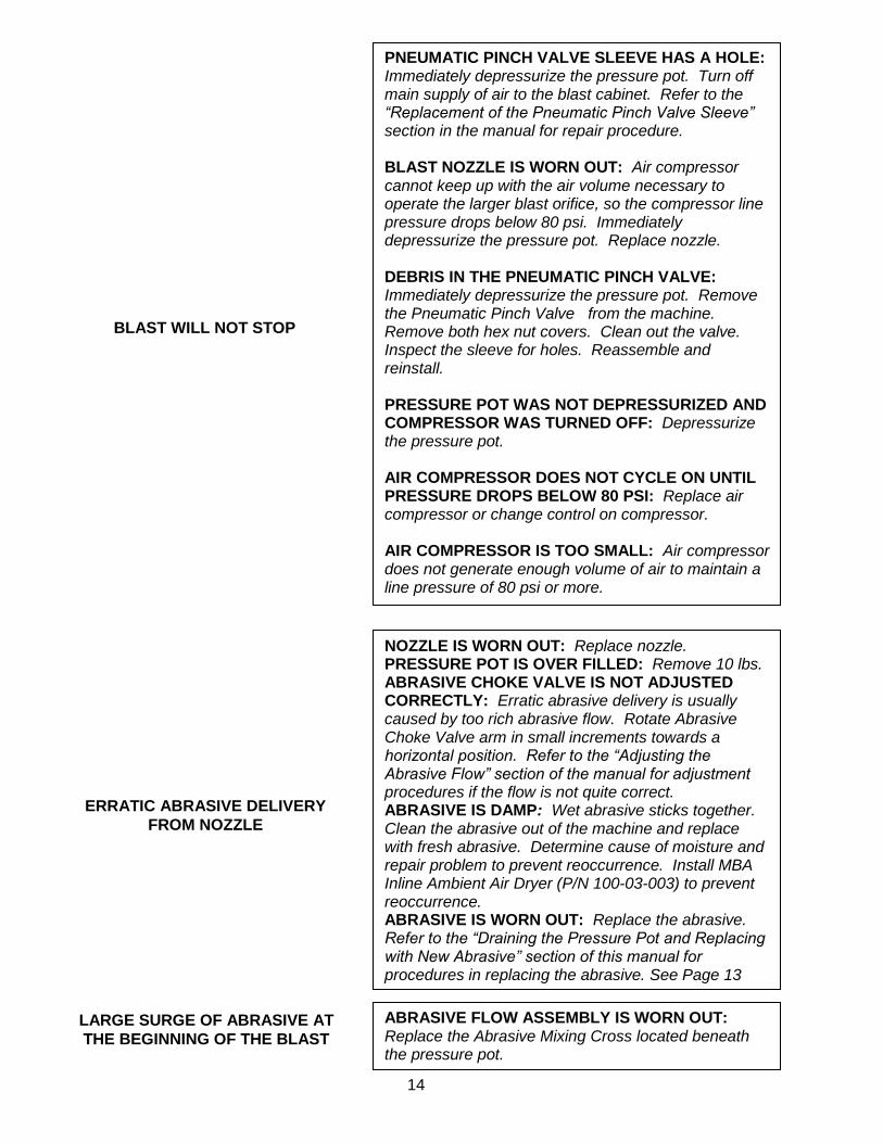
ERRATIC ABRASIVE DELIVERY
FROM NOZZLE
LARGE SURGE OF ABRASIVE AT
THE BEGINNING OF THE BLAST
ABRASIVE FLOW ASSEMBLY IS WORN OUT: Replace the Abrasive Mixing Cross located beneath the pressure pot.
NOZZLE IS WORN OUT: Replace nozzle. PRESSURE POT IS OVER FILLED: Remove 10 lbs. ABRASIVE CHOKE VALVE IS NOT ADJUSTED CORRECTLY: Erratic abrasive delivery is usually caused by too rich abrasive flow. Rotate Abrasive Choke Valve arm in small increments towards a horizontal position. Refer to the “Adjusting the Abrasive Flow” section of the manual for adjustment procedures if the flow is not quite correct. ABRASIVE IS DAMP: Wet abrasive sticks together. Clean the abrasive out of the machine and replace with fresh abrasive. Determine cause of moisture and repair problem to prevent reoccurrence. Install MBA Inline Ambient Air Dryer (P/N 100-03-003) to prevent reoccurrence. ABRASIVE IS WORN OUT: Replace the abrasive. Refer to the “Draining the Pressure Pot and Replacing with New Abrasive” section of this manual for procedures in replacing the abrasive. See Page 13
PNEUMATIC PINCH VALVE SLEEVE HAS A HOLE: Immediately depressurize the pressure pot. Turn off main supply of air to the blast cabinet. Refer to the “Replacement of the Pneumatic Pinch Valve Sleeve” section in the manual for repair procedure. BLAST NOZZLE IS WORN OUT: Air compressor cannot keep up with the air volume necessary to operate the larger blast orifice, so the compressor line pressure drops below 80 psi. Immediately depressurize the pressure pot. Replace nozzle. DEBRIS IN THE PNEUMATIC PINCH VALVE: Immediately depressurize the pressure pot. Remove the Pneumatic Pinch Valve from the machine. Remove both hex nut covers. Clean out the valve. Inspect the sleeve for holes. Reassemble and reinstall. PRESSURE POT WAS NOT DEPRESSURIZED AND COMPRESSOR WAS TURNED OFF: Depressurize the pressure pot. AIR COMPRESSOR DOES NOT CYCLE ON UNTIL PRESSURE DROPS BELOW 80 PSI: Replace air compressor or change control on compressor. AIR COMPRESSOR IS TOO SMALL: Air compressor does not generate enough volume of air to maintain a line pressure of 80 psi or more.
BLAST WILL NOT STOP
15
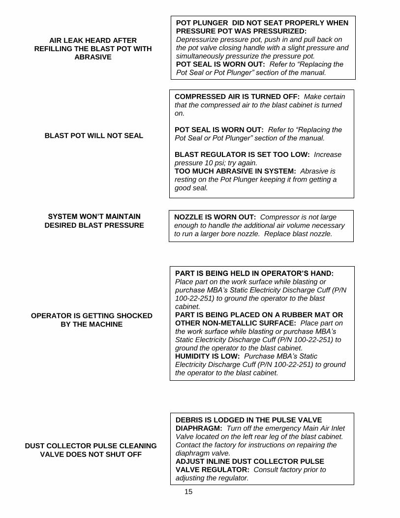
AIR LEAK HEARD AFTER REFILLING THE BLAST POT WITH
ABRASIVE
POT PLUNGER DID NOT SEAT PROPERLY WHEN PRESSURE POT WAS PRESSURIZED: Depressurize pressure pot, push in and pull back on the pot valve closing handle with a slight pressure and simultaneously pressurize the pressure pot. POT SEAL IS WORN OUT: Refer to “Replacing the Pot Seal or Pot Plunger” section of the manual.
OPERATOR IS GETTING SHOCKED
BY THE MACHINE
PART IS BEING HELD IN OPERATOR’S HAND: Place part on the work surface while blasting or purchase MBA’s Static Electricity Discharge Cuff (P/N 100-22-251) to ground the operator to the blast cabinet. PART IS BEING PLACED ON A RUBBER MAT OR OTHER NON-METALLIC SURFACE: Place part on the work surface while blasting or purchase MBA’s Static Electricity Discharge Cuff (P/N 100-22-251) to ground the operator to the blast cabinet. HUMIDITY IS LOW: Purchase MBA’s Static Electricity Discharge Cuff (P/N 100-22-251) to ground the operator to the blast cabinet.
NOZZLE IS WORN OUT: Compressor is not large enough to handle the additional air volume necessary to run a larger bore nozzle. Replace blast nozzle.
SYSTEM WON’T MAINTAIN
DESIRED BLAST PRESSURE
BLAST POT WILL NOT SEAL
COMPRESSED AIR IS TURNED OFF: Make certain that the compressed air to the blast cabinet is turned on. POT SEAL IS WORN OUT: Refer to “Replacing the Pot Seal or Pot Plunger” section of the manual. BLAST REGULATOR IS SET TOO LOW: Increase pressure 10 psi; try again. TOO MUCH ABRASIVE IN SYSTEM: Abrasive is resting on the Pot Plunger keeping it from getting a good seal.
DEBRIS IS LODGED IN THE PULSE VALVE DIAPHRAGM: Turn off the emergency Main Air Inlet Valve located on the left rear leg of the blast cabinet. Contact the factory for instructions on repairing the diaphragm valve. ADJUST INLINE DUST COLLECTOR PULSE VALVE REGULATOR: Consult factory prior to adjusting the regulator.
DUST COLLECTOR PULSE CLEANING
VALVE DOES NOT SHUT OFF

16
ABRASIVE AND/OR DUST IS COMING OUT OF THE EXHAUST
BLOWER
CARTRIDGE FILTER IS NOT TIGHT: A loose filter will allow dust to escape from the dust collector. Refer to “Replacing the Cartridge Filter” section of the manual to determine procedure for tightening the cartridge filter. CARTRIDGE FILTER IS DAMAGED: Refer to “Replacing the Cartridge Filter” section of the manual. RUBBER WASHER NOT PLACED ON GUIDE PIN WHEN NEW FILTER WAS INSTALLED: The rubber washer seals the hole in the bottom of the cartridge filter. Replace the rubber washer on the guide pin. Refer to “Replacing the Cartridge Filter” section of the manual.
NO
SAND

17
CRYSTALBLAST ELITE SYSTEMS DIAGRAMS
AND PARTS LIST
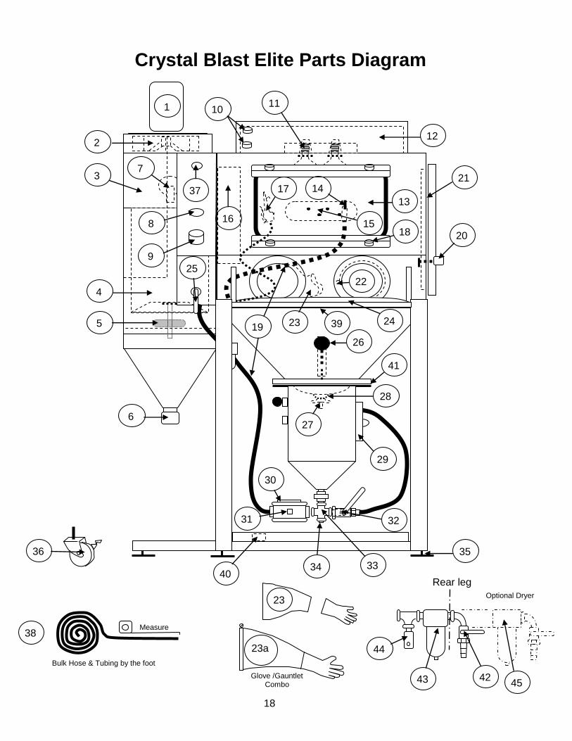
TO FIND THE PART AND PART NUMBER FOR YOUR MACHINE: 1. Determine in which system the part is most likely to be found
(hardware, pneumatic, dust collector, sheet metal or electrical). 2. Refer to the appropriate diagram. 3. Find the location of the part and note the corresponding bubble
number. 4. Refer to the corresponding system section of the parts list and locate
the corresponding bubble number. 5. If there are multiple listings for the bubble number, the correct part and
part number can be determined from the bubble number descriptions.
NO
SAND
18
Bulk Hose & Tubing by the foot
Measure
Glove /Gauntlet Combo
2
5
3
4
6
10 11
29
20
21
12
1
7
13
14
15 16
17
18
22
23 24
9
25
31
27
28
35 36
32
33 34
30
26
8
37
23
23a
38
39
Crystal Blast Elite Parts Diagram
Rear leg
Optional Dryer
19
40
41
42 43
44
45

19
Crystal Blast Elite
Bubble # Description Part Number
1 CB Elite 1/2HP Blower Motor, 3450 RPM 100-05-101
2 CB Elite Blower Impeller, 10” 100-05-312
3 CB Elite Silencer 109-06-100
4 CB Elite Filter Cartridge 110 Sq.Ft. 100-08-005
5 CB Elite Filter Bracket Tightening Assembly, complete 100-08-006
6 CB Elite Dust Collector Drain Cap 100-08-142
7 CB Elite Pulse Valve 100-26-008
8 CB Elite 2” 0-60 PSI Panel Mount Pressure Gauge 100-13-075
9 CB Elite Regulator 100-03-101
10 CB Elite On-Off Selector Switch Complete 100-09-610
11 CB Elite Spot Lights, 90 watt 100-09-052
11 CB Elite Sealing Washer, heat shield 100-11-120
12 CB Elite Air Inlet Filter 100-06-604
13 CB Elite View Window Safety Glass 109-06-129
13 CB Elite View Window Protector Glass, (minimum 5 each) 109-06-030
13 CB Elite Window Bladder Seal sold by the foot per ft 101-11-147
14 CB Elite 3/32” Tungsten Nozzle with Holder for 1/2 hose optional 109-19-093
14 CB Elite 3/32” Boron Carbide Nozzle with Holder 1/2 hose (optional) 109-19-596
14 CB Elite 3/32” Tungsten Nozzle with Holder for 3/8 hose (standard) 109-19-092
14 CB Elite 3/32” Boron Nozzle with Holder for 3/8 hose (optional) 109-19-594
15 CB Elite LED Inspection Lighting 109-05-103
15 CB Elite LED Inspection Lighting Transformer 109-05-102
16 CB Elite Abrasive Separator Reclaimer high efficiency 109-01-101
17 CB Elite Blow-Off Gun 100-18-111
18 CB Elite Window Brackets 109-06-031
18 CB Elite Window Bracket Tightening Knobs 109-06-600
19 CB Elite Abrasive Hose to Nozzle, sold by the foot, 1/2" 109-15-500
19 CB Elite Abrasive Hose to Nozzle, sold by the foot, 3/8” 109-15-375
20 CB Elite Door Strike 100-06-091
20 CB Elite Door Latch 100-06-092
21 CB Elite Door Seal, per 25' roll 100-11-030
22 CB Elite Gauntlet Clamps each 102-12-038
23 CB Elite 6” Cloth Gauntlets pair 109-12-100
23 CB Elite Disposable Latex Gloves, box of 100 109-12-101
23 CB Elite Combo Gloves, 6” (Optional) 100-12-136
24 CB Elite Bolt-On Armrest Complete 100-07-100
24 CB Elite Drop-In Padded Armrest 100-07-101
25 CB Elite Valve, Blow Down,3 way 109-26-001
26 CB Elite Pot Fil l Ball Handle 109-21-010
26 CB Elite Pot Fil l Assembly Complete 109-21-012
26 CB Elite Pot Fil l Return Spring 109-21-011
27 CB Elite Pot Plunger Valve 109-21-201
28 CB Elite Pot Seal 104-21-176
29 CB Elite Pot Access Cover Seal 104-21-171
30 CB Elite Tubomatic Pneumatic Pinch Valve, High Pressure 109-20-300
30 CB Elite Tubomatic Pneumatic Pinch Valve Bladder 109-20-301
30 CB Elite Tubomatic Pneumatic Pinch Valve Brass Core 109-20-302
31 CB Elite Inline Micro Filter Complete 109-20-105
31 CB Elite Replaceable Filter Element 109-20-106
32 CB Elite Abrasive Choke Valve 100-26-098
33 CB Elite Abrasive Mixing Valve Cross (anti surge) 109-21-300

20
34 CB Elite ¾” Drain Plug 109-21-301
35 CB Elite Leg Levelers/Glides 109-18-605
36 CB Elite Locking Wheels Front, Swivel, optional 109-18-604
36 CB Elite Wheels, non-locking, optional 109-18-606
37 CB Elite Manual Pulse Valve 100-26-008
37 CB Elite Pulse Regulator preset 100-03-001
38 CB Elite 1/2” OD Micro Blast Hose sold by the foot 109-15-500
38 CB Elite 3/8” OD Whip Hose 109-15-375
38 CB Elite Hose Adaptor Opitonal 109-20-101
39 CB Elite WorkGrate Expanded Metal 100-25-109
40 CB Elite Pneumatic Foot Valve, Valve only 100-26-086
41 CB Elite CR Steel Scalper Screen Perf. 109-25-002
42 CB Elite Emergency Main Air Inlet Valve 100-26-097
43 CB Elite ¼” Water Trap Air Filter 109-03-102
44 CB Elite Pressure Relief Valve 109-03-103
45 CB Elite Optional Ambient Air Dryer 100-03-003
46 CB Elite Remote Air Filter 109-03-102

21
CRYSTALBLAST ELITE
120VAC
On-Off
white common
black hot
switch box
grounded molded cord
MOTOR C.W. ROTATION
BLOWER MOTOR WIRING
Flexible conduit fitting
2 each 90 watt quartz spot lights
ground lug
LED
12volt trans
2
1
4
3
L1
L2
Gr.
T3 T5
T2
T8
LED Lts

22
WARRANTY
Media Blast & Abrasives, Inc., hereinafter known as “Seller”, warrants the
equipment and products sold hereunder against defects in material and
workmanship for a period of one year from the date of shipment to buyer.
Equipment, products or parts manufactured by others but furnished by
seller will be repaired or replaced only to the extent of the original
manufacturer’s warranty (except motors).
The following conditions apply to limitations:
1. High wear parts are not covered, these parts include windows, window protectors, nozzles, gun parts, abrasive hose and other parts exposed to excessive abrasive contact and wear.
2. Warranty does not apply to misuse of the machine to include improper abrasive type use and or abrasive mesh size used in the equipment. No Media Blast equipment is used with sand, sand will void the machine warranty and is known to be a health hazard.
3. The machine warranty is not transferable and only applies to the original buyer.
4. Replacement warranty parts will be sent at no charge to the buyer for warranty replacement. The cost of labor is not covered under the machine warranty unless preformed at the seller’s facility.
5. A Returned Goods Authorization (RGA) form must be obtained before the product is returned to seller for warranty repair. Without an RGA number the product will not be accepted.
6. Seller’s entire liability, whether under warranty, contract, negligence, or otherwise, shall be limited to repair or replacement, F.O.B. Seller’s place of business, of the original equipment found to be defective within the warranty period.