Embed Size (px)
Citation preview
Operator’s manual Long-seam Machine 5200 series
Version D. July 2009 We reserve the right to make changes in this document
2
Contents:
CHAPTER 1: EU DECLARATION OF CONFORMITY .....................................................- 3 -
CHAPTER 2: GENERAL ...................................................................................................- 4 -
CHAPTER 3: SAFETY ADVICE AND NOTICES ..............................................................- 5 -
CHAPTER 4: HOW THE MACHINE WORKS: ..................................................................- 7 -
Sketch of the automatic machine: ............................................................................................................. - 7 - Starting and stopping the machine:........................................................................................................... - 8 - Failure during start-up, operation or shut-down: ....................................................................................... - 9 - Maintenance: ........................................................................................................................................... - 10 - Basic precautions .................................................................................................................................... - 11 - Maintenance checklist: ............................................................................................................................ - 13 - Storage of this operator’s guide: ............................................................................................................. - 14 -
CHAPTER 5: ASSEMBLY AND DISASSEMBLY ...........................................................- 15 -
Design and construction of the automatic machine: ............................................................................... - 15 - Connecting up: ........................................................................................................................................ - 16 - Disassembly: ........................................................................................................................................... - 16 -
CHAPTER 6: TECHNICAL SPECIFICATIONS ...............................................................- 17 -
External connections: .............................................................................................................................. - 18 - List of replacement parts – long-seam automatic machine..................................................................... - 21 -
IMPORTANT SAFETY NOTICE Always read the operator’s manual carefully and thoroughly before operating the machine. When working, always bear in mind the directions and safety instructions provided in this manual. When installing and
operating the machine, follow the safety directions stated in the chapter of this operator’s manual entitled SAFETY ADVICE AND NOTICES . This operator’s manual must always be available to the persons installing, operating and servicing the machine.
3
Chapter 1: EU Declaration of Conformity
Manufacturer Company name: Migatronic Automation A/S Address: Knøsgaardvej 112 DK-9440 Aabybro, Denmark Telephone: (+45) 96 96 27 00 Internet: www.migatronic-automation.dk
hereby declares that
The machine Make: Long seam automatic machine Type: 5200
has been manufactured in compliance with the provisions of the COUNCIL DIRECTIVE of 14 June 1989 on mutual approximation of the laws of the member states on machines (89/392/EEC as amended by 91/368/EEC and 93/44/EEC) with special reference to annexe 1 of the Directive on essential health and safety requirements in connection with the design and manufacture of machines (cf. Statutory Order of the Danish Working Environment Authority (Arbejdstilsynet) No. 561 of 24 June 1994).
25/8-2006 Keld Kjeldgaard Date Signature
4
Chapter 2: General
The MIGA-5200 long-seam automatic machine is designed for the welding of pipes, vessels and sheets from various materials. MIG/MAG, TIG and plasma welding are all processes which can be applied to this machine.
The automatic machine comes supplied as standard fitted with a type 4005 control system, torch cradle, cross-support for the manual adjustment of torch, pneumatic centring device, foot switch and mandrel lock.
The control system handles functions such as: * Speed regulation * Pre-welding time * Post-welding time * Manual/automatic return/seek of start sensor * Manual operation * Switch with/without arc control * Welding direction * Post-welding/crater filling * Switch with/without welding
If power sources are used in connection with the machine, read the operating manual of the power source prior to starting work.
5
Chapter 3: Safety advice and notices PERSONAL SAFETY
Light and heat emission A welding arc emits radiation which is damaging to the human eye. Even short-term exposure to this radiation can cause permanent damage. Your eyes must be protected against powerful infrared radiation, as well as visible and ultraviolet light by using suitable
radiation protection glass fitted in your welding helmet. Your skin may also be damaged by this radiation. Radiation can cause serious burns. Protect your skin by wearing the helmet, full-body working overalls and gloves. Warn other people in the vicinity of the welding area of the danger of radiation and flying sparks. If possible, screen the workplace off from the surrounding environment. Together with flying sparks, heat radiation from the electric arc and the molten pool constitute a fire risk. For this reason, do not perform welding in the vicinity of flammable materials. Do not put the torch down without first extinguishing the flame. Your working clothes must not contain easily flammable materials or have creases or open pockets which may collect sparks. Wear a fireproof apron if appropriate. After completion of the work, switch off at all socket outlets or at the main valve, and depressurize hose couplings.
Welding fumes The smoke and fumes generated by the welding process are hazardous to health. Therefore extraction systems must be installed in such a way that the fumes which arise during welding are removed effectively. When fumes from degreasing agents are acted on by
ultraviolet radiation from the electric arc, this may produce very toxic phosgene gas. For this reason, all dissolvents, degreasing agents and other potential sources of such fumes must be kept away from the welding area. Avoid inhaling welding fumes and gases. Use benches with extraction or other extraction systems for removal of welding fumes and gases. Use oxygen masks if no such effective extraction system is possible.
Electricity Avoid making contact with live components. The voltages used in connection with welding are not high enough to pose a risk of serious electric shock. However, minor electric shocks may result from damp overalls and the like, and these can frighten the
welder, so potentially posing an indirect safety hazard. In particular, HF high-voltage ignition in TIG and PLASMA welding can generate powerful shocks and cause minor burns under the skin. Contact with live welding parts should therefore be avoided as far as possible. Always ensure that cable insulation, as well as insulation on the torch and machine pin and socket connectors, is fully intact. Always wear dry leather gloves, dry overalls and dry footwear. Furthermore, keep cables, torches and the welding machine itself dry at all times. It is important that the machine’s connections have been set up according to the applicable regulations (power cables, fuses and safety conductor/earth lead). Do not open the machine to expose the live parts. Service and maintenance requiring access to live parts of the machine must only be undertaken by properly qualified personnel. Never leave a dismantled machine connected to the mains supply.
6
Applications: - TIG welding hoses (live cables) and torches must not be placed on the electronic control box. - Do not exceed the maximum dimensions for work pieces laid down in the operator’s manual. - The machine/equipment may only be run by operators who have been trained in its use and who have also worked through the operator’s manual. Removal of safety devices: - Safety devices may not be disabled or removed during operation. Correct placement of work pieces: - Prior to starting work with the machine, the operator must ensure that the work piece has been correctly placed and properly secured.
7
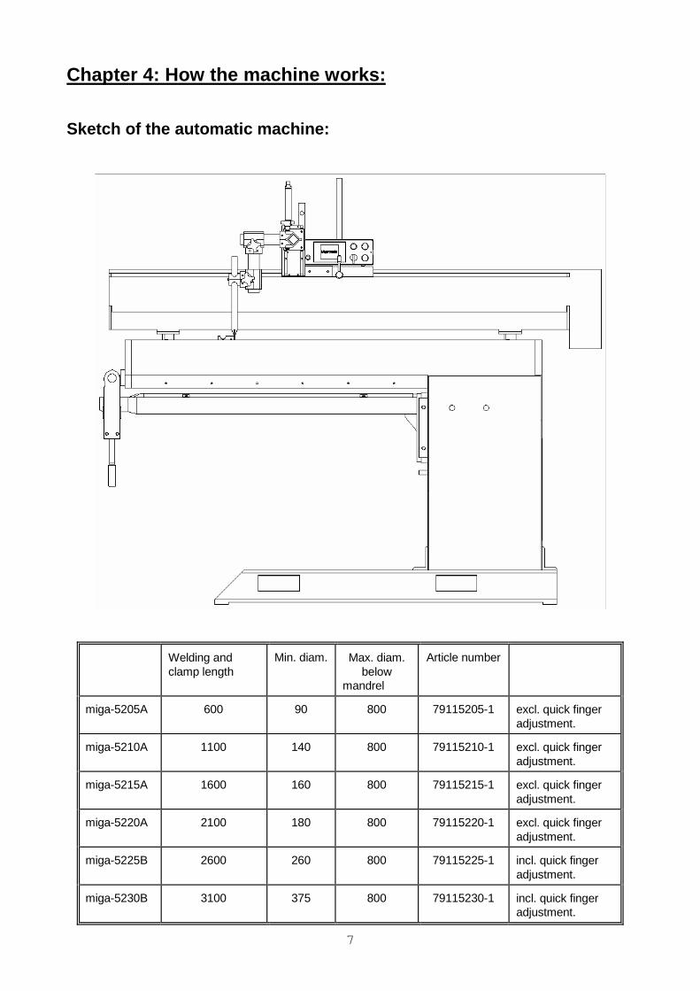
Chapter 4: How the machine works:
Sketch of the automatic machine:
Welding and clamp length
Min. diam. Max. diam. below mandrel
Article number
miga-5205A 600 90 800 79115205-1 excl. quick finger adjustment.
miga-5210A 1100 140 800 79115210-1 excl. quick finger adjustment.
miga-5215A 1600 160 800 79115215-1 excl. quick finger adjustment.
miga-5220A 2100 180 800 79115220-1 excl. quick finger adjustment.
miga-5225B 2600 260 800 79115225-1 incl. quick finger adjustment.
miga-5230B 3100 375 800 79115230-1 incl. quick finger adjustment.
8
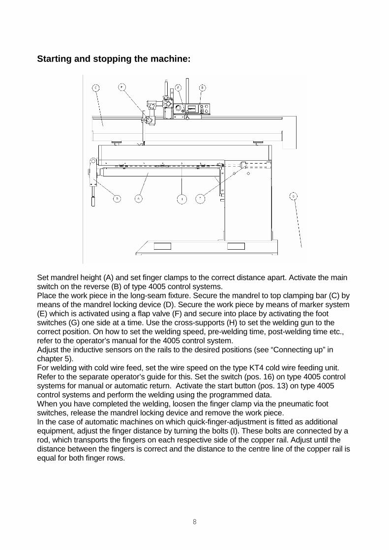
Starting and stopping the machine:
Set mandrel height (A) and set finger clamps to the correct distance apart. Activate the main switch on the reverse (B) of type 4005 control systems. Place the work piece in the long-seam fixture. Secure the mandrel to top clamping bar (C) by means of the mandrel locking device (D). Secure the work piece by means of marker system (E) which is activated using a flap valve (F) and secure into place by activating the foot switches (G) one side at a time. Use the cross-supports (H) to set the welding gun to the correct position. On how to set the welding speed, pre-welding time, post-welding time etc., refer to the operator’s manual for the 4005 control system. Adjust the inductive sensors on the rails to the desired positions (see “Connecting up” in chapter 5). For welding with cold wire feed, set the wire speed on the type KT4 cold wire feeding unit. Refer to the separate operator’s guide for this. Set the switch (pos. 16) on type 4005 control systems for manual or automatic return. Activate the start button (pos. 13) on type 4005 control systems and perform the welding using the programmed data. When you have completed the welding, loosen the finger clamp via the pneumatic foot switches, release the mandrel locking device and remove the work piece. In the case of automatic machines on which quick-finger-adjustment is fitted as additional equipment, adjust the finger distance by turning the bolts (I). These bolts are connected by a rod, which transports the fingers on each respective side of the copper rail. Adjust until the distance between the fingers is correct and the distance to the centre line of the copper rail is equal for both finger rows.

9
Failure during start-up, operation or shut-down: If monitoring of the electric arc (arc control) and welding have been activated, the automatic machine will not start until the electric arc has been established. While the machine is in this waiting mode, the operator must be aware that it may start once the electric arc is started.
10
Maintenance: Regular maintenance is important. This ensures: * A long service life for the machine * Safety * Operational reliability Many of the maintenance tasks are simple for the operator to perform himself using just a few tools. These tasks are described below. However, note that some maintenance tasks require special tools and expertise. Such tasks should be given to qualified Migatronic employees. Even if you are an experienced DIY-mechanic, we recommend that you hand over repairs and maintenance to Migatronic Automation A/S (+45 96 96 27 00).
11
Basic precautions
Warning Disconnect all mains power before working on electrical installations or components.
- Make sure you keep the work area clean and tidy. - Disconnect the power and air supply to the machine when it is not in use or is left unattended.
DAILY CHECKS BEFORE START-UP Inspect the control system: A. Check that all power and fuse lamps light up. B. Ensure that the plug is properly inserted in the rear. C. Perform a cycle without doing any welding. Check mains leads, earth cables, air and gas hoses A. Check for external damage. B. Check for loose connections, elements or leaks. Welding control:
Weld a work piece and compare to the one you retained from the same time the day before. If everything is OK, retain the piece you just welded for start-up on the following day.
WEEKLY CHECK-UP
Clean all important surfaces using compressed air and lubricate sparingly with machine oil.
Sign the maintenance checklist.

12
MONTHLY CHECK-UP In addition to the weekly inspection, check all nuts and Unbrako screws – especially on ball bearings, gun mounting and roll guides. Release carbon in the carbon holder (if any is fitted) and clean with compressed air, checking the carbon length. Check gear motors for leakage in gear gaskets and check wires. Check for play in main bearings. Clean the power sources internally (remember to remove the mains lead!). Sign the maintenance checklist.

13
Maintenance checklist:
Date Weekly check-up Monthly check-up Comments Init.

14
Storage of this operator’s guide: Keep this operator’s manual in a place accessible at all times to operators, maintenance personnel and repairmen.
15
Chapter 5: Assembly and disassembly
Design and construction of the automatic machine:
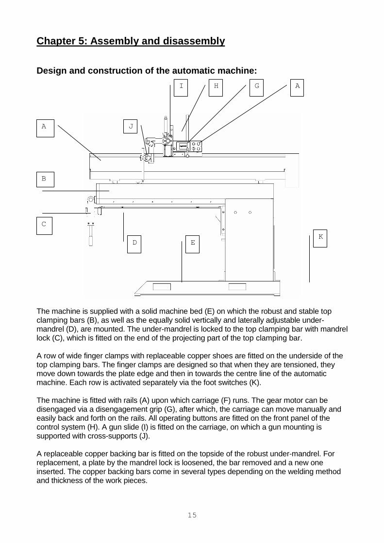
The machine is supplied with a solid machine bed (E) on which the robust and stable top clamping bars (B), as well as the equally solid vertically and laterally adjustable under-mandrel (D), are mounted. The under-mandrel is locked to the top clamping bar with mandrel lock (C), which is fitted on the end of the projecting part of the top clamping bar. A row of wide finger clamps with replaceable copper shoes are fitted on the underside of the top clamping bars. The finger clamps are designed so that when they are tensioned, they move down towards the plate edge and then in towards the centre line of the automatic machine. Each row is activated separately via the foot switches (K). The machine is fitted with rails (A) upon which carriage (F) runs. The gear motor can be disengaged via a disengagement grip (G), after which, the carriage can move manually and easily back and forth on the rails. All operating buttons are fitted on the front panel of the control system (H). A gun slide (I) is fitted on the carriage, on which a gun mounting is supported with cross-supports (J). A replaceable copper backing bar is fitted on the topside of the robust under-mandrel. For replacement, a plate by the mandrel lock is loosened, the bar removed and a new one inserted. The copper backing bars come in several types depending on the welding method and thickness of the work pieces.
C
B
D E K
J
I H G A
A
16
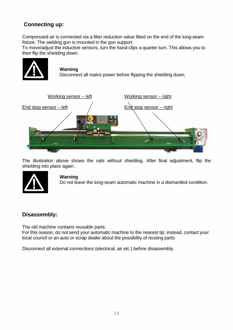
Connecting up: Compressed air is connected via a filter reduction value fitted on the end of the long-seam fixture. The welding gun is mounted in the gun support. To move/adjust the inductive sensors, turn the hand-clips a quarter turn. This allows you to then flip the shielding down.
Warning Disconnect all mains power before flipping the shielding down.
Working sensor – left Working sensor – right End stop sensor – left End stop sensor – right
The illustration above shows the rails without shielding. After final adjustment, flip the shielding into place again.
Warning Do not leave the long-seam automatic machine in a dismantled condition.
Disassembly: The old machine contains reusable parts. For this reason, do not send your automatic machine to the nearest tip; instead, contact your local council or an auto or scrap dealer about the possibility of reusing parts. Disconnect all external connections (electrical, air etc.) before disassembly.
17
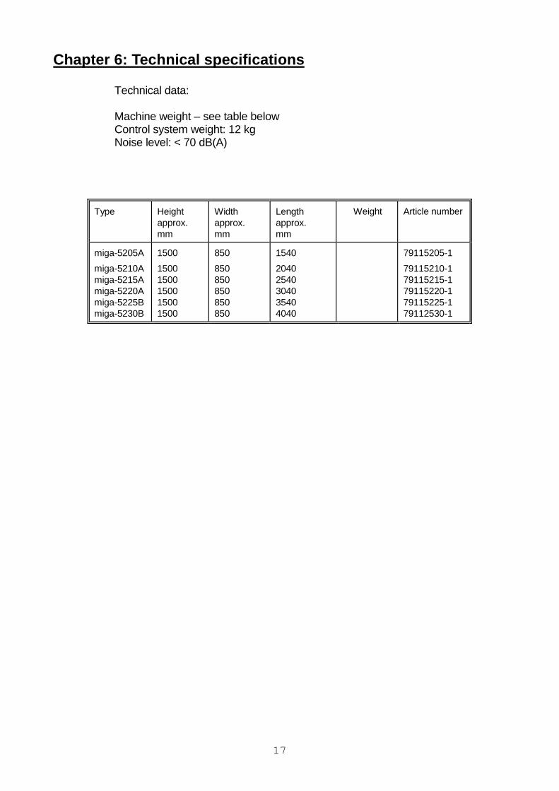
Chapter 6: Technical specifications Technical data: Machine weight – see table below Control system weight: 12 kg Noise level: < 70 dB(A)
Type
Height approx. mm
Width approx. mm
Length approx. mm
Weight Article number
miga-5205A
miga-5210A miga-5215A miga-5220A miga-5225B miga-5230B
1500
1500 1500 1500 1500 1500
850
850 850 850 850 850
1540
2040 2540 3040 3540 4040
79115205-1
79115210-1 79115215-1 79115220-1 79115225-1 79112530-1
18
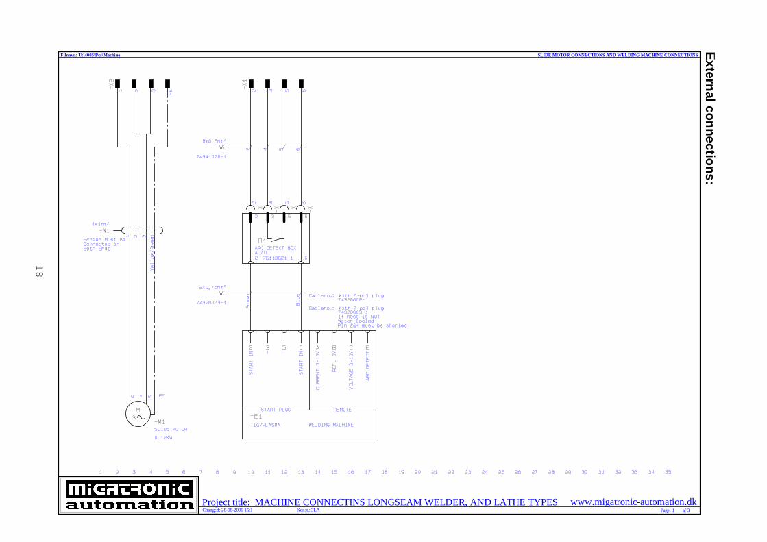
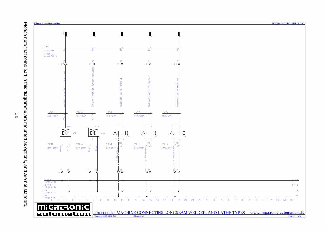
External connections:
www.migatronic-automation.dkProject title: MACHINE CONNECTINS LONGSEAM WELDER, AND LATHE TYPESKonst.:CLA
Filnavn: U:\4005\Pcs\Machine
Changed: 28-08-2006 15:1 Page: 1 af 3
SLIDE MOTOR CONNECTIONS AND WELDING MACHINE CONNECTIONS
19
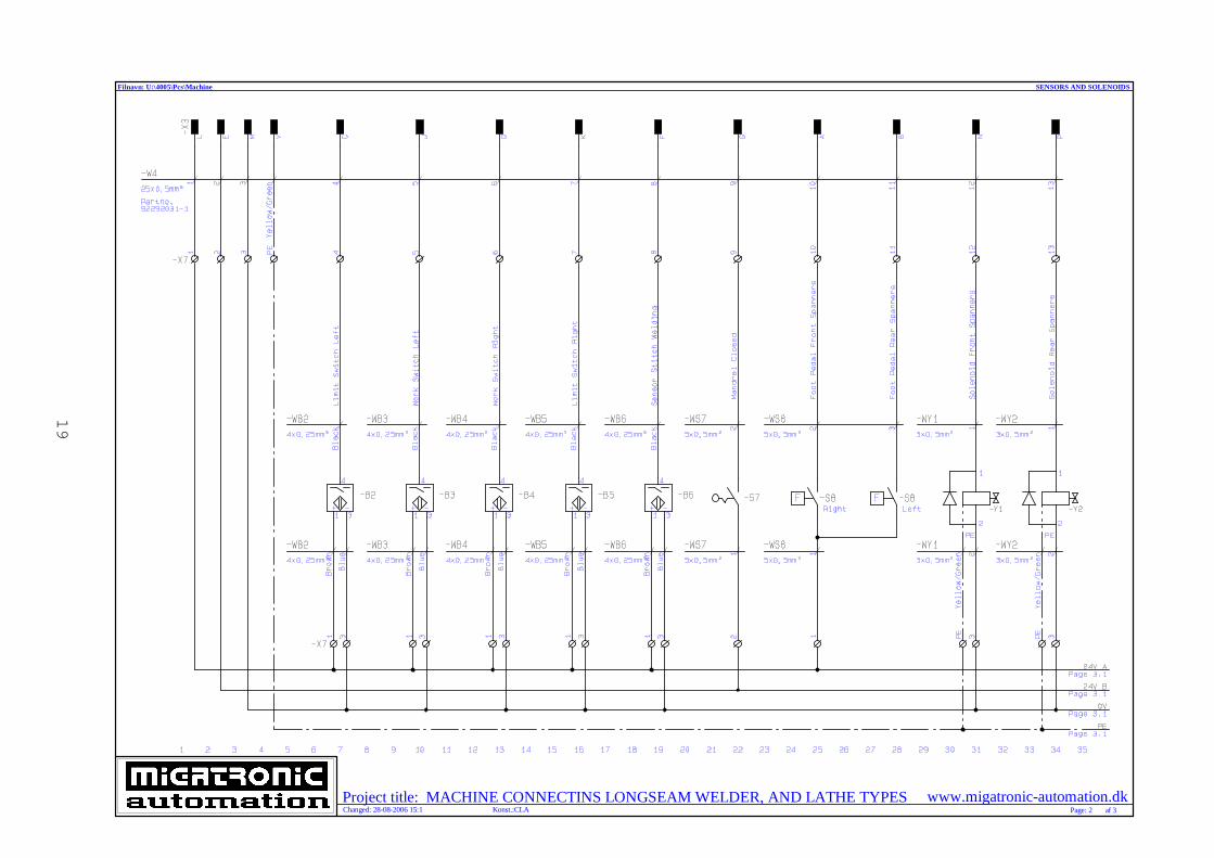
www.migatronic-automation.dkProject title: MACHINE CONNECTINS LONGSEAM WELDER, AND LATHE TYPESKonst.:CLA
Filnavn: U:\4005\Pcs\Machine
Changed: 28-08-2006 15:1 Page: 2 af 3
SENSORS AND SOLENOIDS
20
P
lease note that some part in this diagram
me are m
ounted as options, and are not standard.
www.migatronic-automation.dkProject title: MACHINE CONNECTINS LONGSEAM WELDER, AND LATHE TYPESKonst.:CLA
Filnavn: U:\4005\Pcs\Machine
Changed: 28-08-2006 15:3 Page: 3 af 3
AUTOMATIC TORCH LIFT OPTION
21
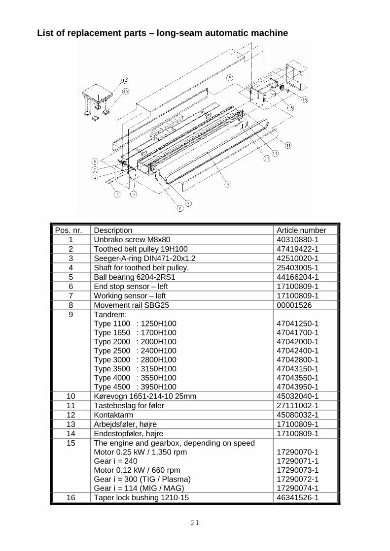
List of replacement parts – long-seam automatic mac hine
Pos. nr. Description Article number 1 Unbrako screw M8x80 40310880-1 2 Toothed belt pulley 19H100 47419422-1 3 Seeger-A-ring DIN471-20x1.2 42510020-1 4 Shaft for toothed belt pulley. 25403005-1 5 Ball bearing 6204-2RS1 44166204-1 6 End stop sensor – left 17100809-1 7 Working sensor – left 17100809-1 8 Movement rail SBG25 00001526 9 Tandrem:
Type 1100 : 1250H100 Type 1650 : 1700H100 Type 2000 : 2000H100 Type 2500 : 2400H100 Type 3000 : 2800H100 Type 3500 : 3150H100 Type 4000 : 3550H100 Type 4500 : 3950H100
47041250-1 47041700-1 47042000-1 47042400-1 47042800-1 47043150-1 47043550-1 47043950-1
10 Kørevogn 1651-214-10 25mm 45032040-1 11 Tastebeslag for føler 27111002-1 12 Kontaktarm 45080032-1 13 Arbejdsføler, højre 17100809-1 14 Endestopføler, højre 17100809-1 15 The engine and gearbox, depending on speed
Motor 0.25 kW / 1,350 rpm Gear i = 240 Motor 0.12 kW / 660 rpm Gear i = 300 (TIG / Plasma) Gear i = 114 (MIG / MAG)
17290070-1 17290071-1 17290073-1 17290072-1 17290074-1
16 Taper lock bushing 1210-15 46341526-1

22