Embed Size (px)
Citation preview

Wood-Mizer® SawmillSafety, Setup, Operation & Maintenance Manual
LT15 rev. E8.13LT15W rev. A1.14
Safety is our #1 concern! Read and understandall safety information and instructions before oper-ating, setting up or maintaining this machine.
Form #798

Active Patents assigned to Wood-Mizer, LLC
Wood-Mizer, LLC has received patents that protect our inventions which are a result of a dedication toresearch, innovation, development, and design. Learn more at: woodmizer.com/patents
©2021 Wood-Mizer LLCPrinted in the United States of America, all rights reserved. No part of this manual may be reproduced in any form by any photographic, electronic, mechanical or other means or used in any information storage and retrieval system with-out written permission from
Wood-Mizer, LLC
8180 West 10th Street
Indianapolis, Indiana 46214

Table of Contents Section-Page
SECTION 1 INTRODUCTION 1-1
1.1 About This Manual.................................................................................1-1 1.2 Getting Service .......................................................................................1-11.3 Specifications .........................................................................................1-11.4 Options and Accessories.........................................................................1-1
SECTION 2 GENERAL SAFETY 2-1
2.1 Safety Symbols.......................................................................................2-12.2 Safety Instructions ..................................................................................2-12.3 Electrical Lockout Procedures................................................................2-3
SECTION 3 SAWMILL ASSEMBLY 3-1
3.1 Leg Assembly.........................................................................................3-13.2 Bed Section Assembly............................................................................3-13.3 Clamp Assembly ....................................................................................3-23.4 Frame Leg Adjustment ...........................................................................3-33.5 Saw Carriage Assembly .........................................................................3-33.6 Feed Rope Assembly..............................................................................3-53.7 Battery Assembly ...................................................................................3-63.8 Sawdust Deflector and Push Handle Assembly .....................................3-73.9 Fuel Tank Installation.............................................................................3-8
SECTION 4 SAWMILL SETUP 4-1
4.1 Sawmill Setup.........................................................................................4-14.2 Carriage Side Adjustment.......................................................................4-24.3 Carriage Locking Pins ............................................................................4-34.4 Replacing The Blade ..............................................................................4-34.5 Tensioning The Blade.............................................................................4-44.6 Tracking The Blade ................................................................................4-44.7 Starting The Engine................................................................................4-5
SECTION 5 SAWMILL OPERATION 5-1
5.1 Loading, Turning And Clamping Logs ..................................................5-15.2 Up/Down Operation ...............................................................................5-25.3 Blade Guide Arm Operation...................................................................5-35.4 Feed Operation .......................................................................................5-45.5 Clutch Operation ....................................................................................5-45.6 Cutting The Log .....................................................................................5-55.7 Edging.....................................................................................................5-55.8 Blade Height Scale .................................................................................5-65.9 Water Lube Operation ............................................................................5-65.10 Loading & Transporting the Sawmill.....................................................5-8
Table of Contents WMdoc021221 iii

Table of Contents Section-Page
SECTION 6 MAINTENANCE 6-1
6.1 Wear Life................................................................................................6-16.2 Blade Guides ..........................................................................................6-16.3 Sawdust Removal ..................................................................................6-16.4 Carriage Track, Wiper & Scrapers .........................................................6-16.5 Vertical Mast Rails .................................................................................6-36.6 Miscellaneous .........................................................................................6-36.7 Blade Wheel Belts ..................................................................................6-36.8 Drive Belt Adjustment............................................................................6-36.9 Up/Down System....................................................................................6-46.10 Charging The Battery .............................................................................6-66.11 Maintenance chart ..................................................................................6-1
6.11 MAINTENANCE LOG 6-1
SECTION 7 TROUBLESHOOTING GUIDE 7-1
7.1 Sawing Problems ....................................................................................7-1
SECTION 8 SAWMILL ALIGNMENT 8-1
8.1 Routine Alignment Procedure ................................................................8-18.2 \Complete Alignment Procedure ............................................................8-6
iv WMdoc021221 Table of Contents

Wood-Mizer® LLC
Limited Product WarrantyWood-Mizer LLC (“Warrantor”), an Indiana corporation with its principal place of business at 8180 West Tenth Street, Indianapolis, IN 46214-2400 USA, warrants to the purchaser (“Purchaser”) thatfor the time periods specifically stated herein and subject to the terms, conditions and limitations stated herein, the equipment manufactured by the Warrantor will be free from defects in material andworkmanship attributable to Warrantor so long as, during the warranty periods stated herein, the equipment is installed, operated and maintained in accordance with the instructions provided byWarrantor.
* Warranty on Options will match the warranty on the primary equipment when purchased on same invoice.
Exclusions from 90 Day, Limited One Year and Two Year Warranty
Warrantor shall have no responsibility under this warranty for any wear components, including, but not limited to: belts, blade guides, blades, electric motor brushes, drum switches, filters, fuses,hoses, bearings (excluding cylindrical drive bearings), bushings, cable carriers, and spark plugs. All wear components are furnished “as is”, without any warranty from Warrantor. This limitedwarranty does not cover any defects caused by misuse, negligence, alterations, damage due to overload, abnormal conditions, excessive operation, accident, or lack of performance of normalmaintenance services.
Several components which are used in the manufacture of the equipment but not manufactured by Warrantor such as cant hooks, power plants, laser sights, batteries, tires, and trailer axles havewarranties provided by the original equipment manufacturer (written copies available upon request). Warrantor does not separately warrant such items. Components or equipment manufactured bythird parties are not covered by this warranty. Warrantor, however, will provide reasonable assistance to the Purchaser to make claims against any warranties applicable to such component parts asprovided by such original equipment manufacturers. Components or equipment manufactured by third parties are not covered by this Warranty.
Five Year Limited Chassis Warranty
The limited five year chassis warranty described above, DOES NOT extend to (a) any damage stemming from accident, improper towing, overload, abuse, misuse, abnormal conditions, negligence,excessive operation, or lack of maintenance, (b) rust caused by exposure to corrosive atmospheric conditions, or (c) the sawmill head, carriage, axle, brakes, or any hydraulic or electrical componentsattached to the chassis.
Warrantor’s Obligations as To Defects
In the event that the equipment fails to perform due to defective materials or workmanship attributable to Warrantor under normal use and service within the established warranty period, Purchaser’ssole and exclusive remedy and Warrantor’s sole liability shall be to replace or repair, in Warrantor’s sole and subjective discretion, any defective part at Warrantor’s principal place of business withoutcost to the Purchaser if such defect exists. The determination of whether a product is defective shall be made by Warrantor in Warrantor’s sole and subjective discretion. The Purchaser must notifyWarrantor prior to shipping any defective part. Warrantor, at its sole discretion, may cover expenses incurred in shipping the defective part to Warrantor for evaluation; provided, however, thatWarrantor will not be responsible for labor, travel time, mileage, removal, installation or incidental or consequential damages. However, any part in excess of 140 pounds must be returned by thePurchaser, to the Warrantor’s nearest authorized facility at the Purchaser’s expense, if return is requested by Warrantor. Warrantor shall have a reasonable time within which to replace or repair thedefective part. If Warrantor determines that the product is not defective under the terms of this warranty in Warrantor’s sole and subjective discretion, then Purchaser shall be responsible for anyexpenses incurred by Warrantor in returning the equipment to the Purchaser.
Limitations and Disclaimers of Other Warranties
EXCEPT FOR THE EXPRESS WARRANTY PROVISIONS STATED ABOVE, WARRANTOR DISCLAIMS ALL WARRANTIES, EXPRESS AND/OR IMPLIED, INCLUDING WITHOUTLIMITATION, THE IMPLIED WARRANTIES OF MERCHANTABILITY, AND FITNESS FOR A PARTICULAR PURPOSE, NONINFRINGEMENT AND TITLE. No representation or other affirmationof fact by representatives of Warrantor, whether verbal or in writing, including photographs, brochures, samples, models, or other sales aids, shall constitute a warranty or other basis for any legalaction against Warrantor. There are no other representations, promises, agreements, covenants, warranties, guarantees, stipulations or conditions, express or implied, by Warrantor except asexpressly set forth herein. THE ORIGINAL PURCHASER AND ANY INTENDED USER OR BENEFICIARY OF THIS EQUIPMENT, SHALL NOT BE ENTITLED TO RECOVER ANY INDIRECT,SPECIAL, PUNITIVE, EXEMPLARY, CONSEQUENTIAL, SPECIAL, OR INCIDENTIAL DAMAGES OR LOSES, INCLUDING BUT NOT LIMITED TO, DAMAGES OF LOST PRODUCTION, LOSTREVENUE, LOST PRODUCT, LOST PROFITS, LOST BUSINESS, LOSS OF USE, LOSS OF GOODWILL, OR BUSINESS INTERRUPTION, FROM WARRANTOR FOR ANY REASONWHATSOEVER INCLUDING WITHOUT LIMITATION WARRANTY OR DEFECT IN THE PRODUCT REGARDLESS OF THE SOLE, JOINT AND/OR CONCURRENT NEGLIGENCE, BREACHOF CONTRACT, BREACH OF WARRANTY, STRICT LIABILITY IN TORT OR STATUTORY CLAIMS OR OTHER LEGAL FAULT OR RESPONSIBILITY OF EITHER WARRANTOR ORPURCHASER OR ITS EMPLOYEES OR AGENTS. Warrantor does not warrant that its equipment meets or complies with the requirements of any particular safety code or governmentalrequirements.
Defective items replaced under the terms of this warranty become the property of Warrantor.
Design Changes
Warrantor reserves the right to change the design of its products from time to time without notice and without obligation to make corresponding changes in or to its products previously manufactured.
Rights of Purchasers
The validity and effect of this limited warranty as well as its interpretation, operation and effect, shall be determined exclusively by the principles of law and equity of the State of Indiana, USA. Thislimited warranty gives Purchaser specific legal rights. Purchaser may also have other rights, which may vary from state to state. Some states may not allow limitations as to the duration of impliedwarranties or to the exclusion or limitation of incidental or consequential damages, so some of the limitations and exclusions detailed set forth above may not apply. In the event that any one or moreof the provisions of this warranty shall be or become invalid, illegal or unenforceable in any respect, the validity, legality and enforceability of the remaining provisions of this warranty shall not beaffected thereby.
Interpretations
This Warranty constitutes the entire warranty agreement between Warrantor and Purchaser and supersedes any prior understandings or agreements pertaining to the same subject matter. Thiswarranty cannot be amended except in writing which refers to this warranty which is signed by both Warrantor and Purchaser.
© 2020 Wood-Mizer LLC – 8180 West 10th Street, Indianapolis, IN 46214 FORM#1814ENG
PRODUCT MODEL CLASSLENGTH OF WARRANTY
EFFECTIVE DATEUSA & CANADA NON USA & CANADA
Portable Sawmills, Resaws, Edgers LT, LX, HR, EG Two years One year
Date of purchase Portable Sawmills with Chassis LT28, LT35, LT40, LT50, LT70, LX450
Two years, excluding the chassis, which chas-sis shall have a five year warranty
One year
Industrial Sawmills, Resaws, Edgers WM, HR, EG, TVS, SVS One year One year Date of purchase or date of installation / training (if applica-ble), whichever occurs first, not to exceed 6 months from date of purchase
TITAN Industrial WB, TV, HR, EG, EA, MR One year One year
Material Handling TWC, IC, TD, LD, GC, CR, CB, CC One year One year
Blade Maintenance Equipment BMS, BMT, BMST One year One year
Date of purchase
Options and Accessories Various One year* One year*
Moulders, Extractors, Kilns MP, MD, KS, KD One year One year
Slab Flattener MB Two years One year
Pallet Equipment PD, PC One year One year
Log Splitters FS One year One year
Replacement Parts Various 90 days 90 days

IntroductionAbout This Manual1
1-1 WM doc 2/12/21 Introduction
SECTION 1 INTRODUCTION 1.1 About This Manual
This manual replaces any previous information received on your Wood-Mizer® equipment.
The information and instructions in this manual do not amend or extend the limited warranties for the equipment given at the time of purchase.
1.2 Getting ServiceFor contact information, sales, service, parts, and additional manuals, sign into your account on https://woodmizer.com, or call inside the USA: 1-800-553-0182 or from outside the USA: 317-271-1542
1.3 Specifications
Equipment specification are included in the Online Manuals, which are found at https://apps.woodmizer.com/Manuals/Manu-als.aspx?parent=0.
1.4 Options and Accessories
Your Wood-Mizer product may have options that can be added to the machine or accessories available to purchase. Different power configurations are also available.
Option: Your specific product can have accessories installed at the factory, or installed in the field. For example, a sawmill might have a debarker or power-feed option.
Accessory: Your specific product may have accessories added to the machine that are not available to be installed at the fac-tory. They may only be installed in the field. For example, a sawmill might have a bed extension or a Shingle/Lap Sider acces-sory.
Power Options: Your specific product power option is detailed based on the specific product number purchased.
This product has the following options available:
Document Name Type
1567 Power Feed Option, Accessory
1337 Lathe-Mizer Accessory
2068 LT15GO2 Trailer Accessory
1308 Lathe-Mizer Tenon Kit Accessory
1540 Load Assist Kit Option Accessory
903 Shingle Lap Sider Accessory
1098 D10 Yanmar Engine
1631 D17 Kohler Engine
1355 D19 Deutz Engine
1128 E10 1-Phase Engine
1100 E10 Lincoln Engine
1744 G18/G19 Kohler Engine
1204 G25 Kohler Engine

General SafetySafety Symbols 2
SECTION 2 GENERAL SAFETY
2.1 Safety Symbols
The following symbols and signal words call your attention to instructions concerning your personal safety. Be sure to observe and follow these instructions.
DANGER! indicates an imminently hazardous situa-tion which, if not avoided, will result in serious injury ordeath.
WARNING! suggests a potentially hazardous situa-tion which, if not avoided, could result in serious injuryor death.
CAUTION! refers to potentially hazardous situa-tions which, if not avoided, may result in minor or mod-erate injury or damage to equipment.
NOTICE indicates vital information.
2.2 Safety Instructions
OWNER/OPERATOR'S RESPONSIBILITY
The procedures listed in this manual may not include all ANSI, OSHA, or locally required safety procedures. It is the owner/operator’s responsibility and not Wood-Mizer LLC to ensure all operators are properly trained and informed of all safety protocols. Owner/Operators are responsible for following all safety procedures when operating and perform-ing maintenance to the equipment.
Observe ALL Safety Instructions
NOTICE Read the entire Operator's Manual beforeoperating this equipment.
Note all safety warnings throughout this manual andthose posted on the machine.
Be able to access this manual at all times while oper-ating this equipment.
Read additional manufacturer’s manuals and observetheir applicable safety instructions.
Only persons who have read and understood theentire operator's manual should operate this equip-ment.
This equipment is not intended for use by or aroundchildren.
It is the owner/operator's responsibility to comply with all applicable federal, state, and local laws, rules, and regulations regarding the ownership, operation, and transporting your equipment.
Operators should become thoroughly familiar with and com-ply with these applicable laws for operating and transporting equipment.
WARNING! Clean sawdust from all guards, vents,control boxes, or any area where sawdust may gatherafter every shift. Failure to do so may result in fire,causing death or serious injury.
WEAR SAFETY CLOTHING
WARNING! Secure all loose clothing and jewelrybefore operating the mill.
Always wear eye, ear, and foot protection when oper-ating or servicing the mill.
Wear hand protection while servicing the mill blades.
Wear respiratory protection when sawing woods thatrequire it. (It is up to the sawyer to know which woodsrequire respiratory protection.)
HANDLE FUEL/LUBRICANTS SAFELY
DANGER! Due to the flammable nature of fuel andoil, never smoke, weld, grind or allow sparks near yourengine or storage tanks, especially during times offueling.
Do not allow fuel to spill on a hot engine during fuelingoperations or otherwise.
WARNING! Store gasoline away from sawdust andother flammable materials.
Do not use flammable fuels or liquids such as dieselfuel. Use ONLY water and Wood-Mizer Lube Additivewith the water lube accessory.
MILL SETUP
DANGER! Do not operate the mill without all covers and guards in place.
WARNING! Set up the mill on solid, level ground.
Use a minimum of three people (four recommended) to safely load or unload the sawmill from a pickup truck.
Do not lift the sawmill using ropes, cables or chains, etc. The weight is off balanced and may cause the mill to fall.
Keep all persons out of the area between the frame rails while loading and unloading the sawmill.
CHECK SAWMILL BEFORE OPERATION
DANGER! Ensure all guards and covers are inplace and secured before operating or towing the saw-mill.
Use the safety retainer pin and cable to fasten bladehousing covers.
WARNING! Do not operate the sawmill without thebed end retaining brackets properly installed; the sawhead may to fall from the log bed. Failure to follow thismay result in serious injury or death.
KEEP PERSONS AWAY
DANGER! Keep all persons out of the path of mov-ing equipment and logs when operating sawmill orloading and turning logs.
Ensure the blade is disengaged and all persons areout of the path of the blade before starting the engineor motor.
KEEP HANDS AWAY
DANGER! Remove power before clearing debris orany other maintenance activity.
General Safety WM doc 2/12/21 2-1

General SafetyObserve ALL Safety Instructions2
Disengage the blade and shut off the sawmill enginebefore changing the blade.WARNING! Avoid contact with any hot parts(motors).
Allow the system to cool sufficiently before begin-ning any service function, including debrisremoval.
Avoid contact with sharp edges of the cutting blades.
Stay a safe distance from rotating members (shafts,pulleys, fans, etc.) and ensure loose clothing or longhair does not engage rotating members
Do not spin the blade wheels by hand. Spinning theblade wheels by hand may result in serious injury.
Disengage the clutch/brake mechanism whenever thesawmill is not cutting.
Do not adjust the engine drive belt with the engine run-ning.
Keep hands, feet, etc., clear of exiting sawdust chutewhen operating sawmill.
UP/DOWN SYSTEM SAFETY
WARNING! Secure the saw head with a chain witha minimum of 1900 lbs. working load capacity beforeadjusting the up/down chain.
Release pressure from the up/down assist prior to per-forming any service to the assembly. Parts are undertension and may fly apart.
Do not disassemble the pressurized cylinder. Parts areunder pressure and may fly apart or damage the cylin-dar.
KEEP SAFETY LABELS IN GOOD CONDITION
NOTICE Ensure that all safety decals are clean andreadable. Replace all damaged safety decals to pre-vent personal injury or damage to the equipment. Con-tact your local distributor, or call your CustomerService Representative to order more decals.
NOTICE If replacing a component that has a safetydecal affixed to it, ensure the new component also hasthe safety decal affixed.
KEEP MILL AND AREA AROUND MILL CLEAN
WARNING! Maintain a clean and clear path for allnecessary movement around the mill and materialstacking areas.
Do not allow children in the area of the mill. Failure tofollow this may result in death or serious injury.
GAS OR DIESEL ENGINE OPERATION
DANGER! Operate your engine/machine only inwell ventilated areas.
Do notoperate an engine with a fuel or oil leak.
WARNING! Do not operate engine without properand operational spark arrester/muffler.
DISPOSE OF WOOD BY-PRODUCTS PROPERLY
NOTICE Properly dispose of all wood by-products,including sawdust, chips, and other debris, includingoperation waste such as oil, filters, etc.
WORKING WITH BATTERIES
DANGER! Batteries expel explosive gases; keepsparks, flames, burning cigarettes, or other ignitionsources away at all times. Failure to follow this willresult in serious injury or death.
WARNING! Always wear safety goggles and a faceshield when working near batteries. Failure to followthis could result in serious injury or death.
Wash hands after handling batteries to remove possi-ble lead, acid, or other contaminants. Failure to followthis could result in serious injury or death.
Charge the battery in a well ventilated area. Failure tofollow this could result in serious injury or death.
Do not attempt to charge a frozen battery. Failure tofollow this could result in serious injury or death.
CAUTION! Do not overcharge the battery. Over-charging may reduce the overall service life of the bat-tery.
Ensure the battery is fully charged before transportingthe sawmill. If the battery is not fully charged, exces-sive vibration could reduce the overall service life ofthe battery.
NOTICE When working with batteries, use extremecare to avoid spilling or splashing electrolyte (dilutesulfuric acid) as it can destroy clothing and burn theskin.
EMERGENCY TREATMENT FOR CONTACT WITH BATTERY COMPONENTS (LEAD/SULFURIC ACID) per SDS (Safety Data
Sheet):
EYE CONTACT
Sulfuric Acid and Lead: Flush eyes immedi-ately with large amounts of water for at least 15 minutes while lifting lids. Seek immediate medi-cal attention.
SKIN CONTACT
Sulfuric Acid: Flush affected area(s) with large amounts of water using deluge emergency shower, if available, shower for at least 15 min-utes. Remove contaminated clothing, including shoes. If symptoms persist, seek medical atten-tion. Wash contaminated clothing before reuse. Discard contaminated shoes.Lead: Wash immediately with soap and water.
INGESTION Sulfuric Acid: Administer large amounts of water. Do NOT induce vomiting or aspiration into the lungs may occur and can cause perma-nent injury or death; consult physician.
INHALATION Sulfuric Acid: Remove to fresh air immediately. If not breathing, give artificial respiration. If breathing is difficult, give oxygen. Consult a physician.Lead: Remove from exposure, gargle, wash nose and lips; consult physician.
2-2 WM doc 2/12/21 General Safety

General SafetyElectrical Lockout Procedures 2
2.3 Electrical Lockout Procedures
RULES FOR USING LOCKOUT PROCEDURE
The equipment shall be locked out to protect against acciden-tal or inadvertent operation when such operation could cause injury to personnel. Do not attempt to operate any switch or valve bearing a lock.
LOCKOUT PROCEDURES MUST BE USED DURING, BUT NOT LIMITED TO:
Changing or adjusting blades Unjamming operations Cleaning Mechanical repair Electrical maintenance Retrieval of tools/parts from work area Activities where guards or electrical panel guard is open or
removed
MAINTENANCE HAZARDS INCLUDE, BUT NOT LIM-ITED TO:
Blade contact Pinch points Kickbacks Missiles (thrown blades/wood chips) Electrical
FAILURE TO LOCKOUT MAY RESULT IN, BUT NOT LIMITED TO:
Cut Crush Blindness Puncture Electrocution Serious injury and death Amputation Burn Shock
TO CONTROL MAINTENANCE DANGERS:
Lockout procedures must be followed (see OSHA regula-tion 1910.147).
Never rely on machine stop control for maintenance safety(emergency stops, on/off buttons, interlocks).
Do not reach into moving blades or feed systems. Allow allcoasting parts to come to a complete stop.
Electrical power supply and air supply must both be lockedout.
Where established lockout procedures cannot be used(electrical troubleshooting or mechanical dynamic trouble-shooting), alternative effective protective techniques shallbe employed which may require special skills and plan-ning.
Always follow safe operations practices in the workplace.
EQUIPMENT LOCKOUT PROCEDURE
Lockout procedures per OSHA regulation 1910.147, appen-dix A:
GENERAL
The following simple lockout procedure is provided to assist owner/operators in developing their procedures so they meet the requirements of OSHA regulation 1910.147. When the energy isolating devices are not lockable, tagout may be used, provided the owner/operator complies with the provi-sions of the standard which require additional training and more rigorous periodic inspections. When tagout is used and the energy isolating devices are lockable, the owner/operator must provide full operator protection (see OSHA regulation 1910.147, paragraph (c)(3)) and additional training and more rigorous periodic inspections are required. For more complex systems, more comprehensive procedures may need to be developed, documented, and utilized.
PURPOSE
This procedure establishes the minimum requirements for the lockout of energy isolating devices whenever maintenance or servicing is done on machines or equipment. It shall be used to ensure that the machine or equipment is stopped, isolated from all potentially hazardous energy sources and locked out before personnel perform any servicing or maintenance where the unexpected enervation or start-up of the machine or equipment or release of stored energy could cause injury.
COMPLIANCE WITH THIS PROGRAM
All personnel are required to comply with the restrictions and limitations imposed upon them during the use of lockout. The authorized personnel are required to perform the lockout in accordance with this procedure. All operators, upon observ-ing a machine or piece of equipment which is locked out to perform servicing or maintenance shall not attempt to start, energize, or use that machine or equipment.
SEQUENCE OF LOCKOUT
1. Notify all affected personnel that servicing or maintenance isrequired on a machine or equipment and that the machine orequipment must be shut down and locked out to perform theservicing or maintenance.
2. The authorized employee shall refer to the company proce-dure to identify the type and magnitude of the energy that themachine or equipment utilizes, shall understand the hazardsof the energy, and shall know the methods to control theenergy.
3. If the machine or equipment is operating, shut it down by thenormal stopping procedure (depress the stop button, openswitch, close valve, etc.).
4. De-activate the energy isolating device(s) so that themachine or equipment is isolated from the energy source(s).
5. Lock out the energy isolating device(s) with assigned individ-ual lock(s).
6. Stored or residual energy (such as that in capacitors, springs,elevated machine members, rotating flywheels, hydraulic sys-tems, and air, gas, steam, or water pressure, etc.) must bedissipated or restrained by methods such as grounding, repo-sitioning, blocking, bleeding down, etc.
7. Ensure that the equipment is disconnected from the energysource(s) by first checking that no personnel are exposed,then verify the isolation of the equipment by operating thepush button or other normal operating control(s) or by testingto make certain the equipment will not operate.
General Safety WM doc 2/12/21 2-3

General SafetyElectrical Lockout Procedures2
CAUTION! Return operating control(s) to neutral or"off" position after verifying the isolation of the equip-ment.8. The machine or equipment is now locked out.
RESTORING EQUIPMENT TO SERVICE
When the servicing or maintenance is completed and the machine or equipment is ready to return to normal operating condition, the following steps shall be taken.
1. Check the machine or equipment and the immediate areaaround the machine to ensure that nonessential items havebeen removed and that the machine or equipment compo-nents are operationally intact.
2. Check the work area to ensure that all personnel have beensafely positioned or removed from the area.
3. Verify that the controls are in neutral.
4. Remove the lockout devices and re-energize the machine orequipment.
NOTE: The removal of some forms of blocking mayrequire re-enervation of the machine before saferemoval.
5. Notify affected personnel that the servicing or maintenance iscompleted and the machine or equipment is ready for use.
PROCEDURE INVOLVING MORE THAN ONE PERSON
In the preceding steps, if more than one individual is required to lock out the equipment, each shall place his own per-sonal lock on the energy isolating devices.
2-4 WM doc 2/12/21 General Safety

Sawmill AssemblyLeg Assembly 3
SECTION 3 SAWMILL ASSEMBLY
NOTICE LT15 shipped after 5/12 only: The saw-mill is shipped properly secured to the pallet. Before starting sawmill assembly, remove the shipping brackets securing the sawmill to the pal-let. Also, remove the shipping bracket and the shipping bolt securing the saw head to the mast.
See Section SECTION 8 for complete alignment instruc-tions.
3.1 Leg Assembly
NOTE: If assembling the sawmill to an LT15TRG trailer (LT15GO), skip this step. Refer to the trailer option manual for assembly instructions then return to the next section when instructed to complete sawmill assembly.
1. Place a hex nut on each leg approximately half way down the shaft.
2. Slide the outrigger (nut keeper) plate into the mount-ing bracket.
3. Position the square nut between the plate and the bracket.
4. Thread each leg through the bracket, the square nut, and the plate. (See FIG. 3-2.)
5. Tighten the hex nut around the leg bracket (requires 1 5/16” wrench).
6. Assemble four legs to each bed section.
3.2 Bed Section Assembly
NOTE: Disassemble any ship-ping straps from the bed sec-tions before beginning.
1. Lay the bed sections end-to-end so the track portion of each section is on the same side.
2. Slide the sections together and secure with four 1/2-13 x 5” hex head bolts and nylon lock nuts.
3.
NOTE: Make sure the top surfaces of the outer side of the bed sections are aligned. It may be necessary to pry one bed section up or down until the sur-faces are aligned, then tighten the bolts.
150209-3
Remove shipping brackets
Remove shipping bolt
FIG. 3-1
150228-1B
Square Nut
Hex Nut
Plate
FIG. 3-2
150070-1C
Align top bed tube surfaces
1/2-13 x 5" HexHead Bolt (4)
1/2-13 NylonLock Nut (4)
FIG. 3-3
Sawmill Assembly WM doc 2/12/21 3-1

Sawmill AssemblyClamp Assembly3
Insert the splice pins into the holes in the track rail and secure with two 3/8-16 x 1” hex head bolts.
TIP: The threaded holes at the end of the splice are provided to help remove the splice if you wish to disassemble the sawmill. Remove the two splice bolts from the middle holes and thread into the end holes. Evenly turn the bolts clock-wise to push the splice pins out of the track rail holes.
3.3 Clamp Assembly
Assemble a log clamp to the bed as shown below.
FIG. 3-4
FIG. 3-5
150070B
Thread bolts in endholes to remove
splice
3/8-16 x 1"Hex Head Bolt (2
Splice
150204-2D
Clamp
Bolt
Lock Nut
FlatWasher
Flat Washer
Spacer
3-2 WM doc 2/12/21 Sawmill Assembly
Sawmill AssemblyFrame Leg Adjustment 3
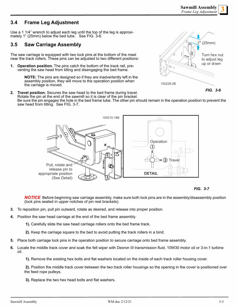
3.4 Frame Leg Adjustment
Use a 1 1/4” wrench to adjust each leg until the top of the leg is approxi-mately 1” (25mm) below the bed tube. See FIG. 3-6.
3.5 Saw Carriage Assembly
The saw carriage is equipped with two lock pins at the bottom of the mast near the track rollers. These pins can be adjusted to two different positions:
1. Operation position. The pins catch the bottom of the track rail, pre-venting the saw head from tilting and disengaging the bed frame.
NOTE: The pins are designed so if they are inadvertently left in the assembly position, they will move to the operation position when the carriage is moved.
2. Travel position. Secures the saw head to the bed frame during travel. Rotate the pin at the end of the sawmill so it is clear of the pin bracket. Be sure the pin engages the hole in the bed frame tube. The other pin should remain in the operation position to prevent the saw head from tilting. See FIG. 3-7.
NOTICE Before beginning saw carriage assembly, make sure both lock pins are in the assembly/disassembly position (lock pins seated in upper notches of pin rest brackets).
3. To reposition pin, pull pin outward, rotate as desired, and release into proper position.
4. Position the saw head carriage at the end of the bed frame assembly.
1). Carefully slide the saw head carriage rollers onto the bed frame track.
2). Keep the carriage square to the bed to avoid putting the track rollers in a bind.
5. Place both carriage lock pins in the operation position to secure carriage onto bed frame assembly.
6. Locate the middle track cover and soak the felt wiper with Dexron III transmission fluid, 10W30 motor oil or 3-in-1 turbine oil.
1). Remove the existing hex bolts and flat washers located on the inside of each track roller housing cover.
2). Position the middle track cover between the two track roller housings so the opening in the cover is positioned overthe feed rope pulleys.
3). Replace the two hex head bolts and flat washers.
FIG. 3-7
150228-2B
1" (25mm)
Turn hex nutto adjust legup or down
FIG. 3-6
150210-18B
2
1
Travel
Operation
DETAIL
Pull, rotate andrelease pin to
appropriate position(See Detail)
Sawmill Assembly WM doc 2/12/21 3-3
Sawmill AssemblySaw Carriage Assembly3
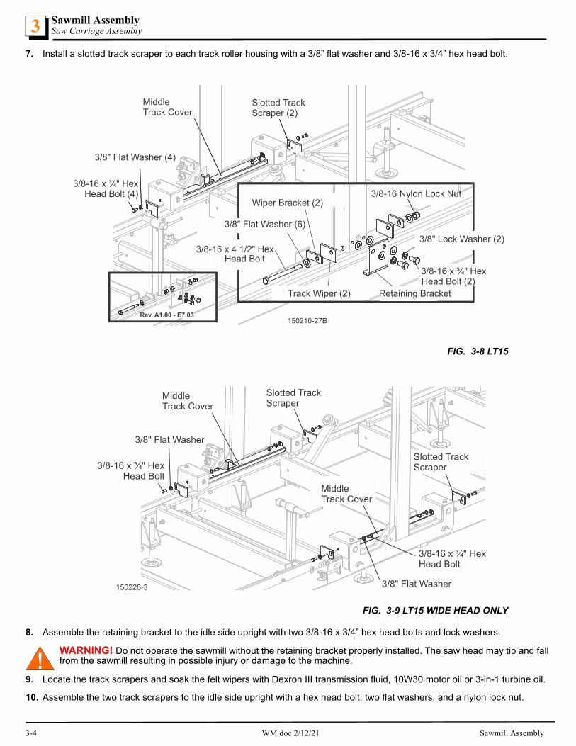
7. Install a slotted track scraper to each track roller housing with a 3/8” flat washer and 3/8-16 x 3/4” hex head bolt.
8. Assemble the retaining bracket to the idle side upright with two 3/8-16 x 3/4” hex head bolts and lock washers.
WARNING! Do not operate the sawmill without the retaining bracket properly installed. The saw head may tip and fall from the sawmill resulting in possible injury or damage to the machine.
9. Locate the track scrapers and soak the felt wipers with Dexron III transmission fluid, 10W30 motor oil or 3-in-1 turbine oil.
10. Assemble the two track scrapers to the idle side upright with a hex head bolt, two flat washers, and a nylon lock nut.
FIG. 3-8 LT15
FIG. 3-9 LT15 WIDE HEAD ONLY
150210-27B 150210-27BRev. A1.00 - E7.03
3/8" Flat Washer (6)
3/8" Flat Washer (4)
3/8" Lock Washer (2)
Slotted TrackScraper (2)
Track Wiper (2)
3/8-16 x ¾" HexHead Bolt (4)
MiddleTrack Cover
3/8-16 x ¾" HexHead Bolt (2)
3/8-16 x 4 1/2" HexHead Bolt
Wiper Bracket (2)
Retaining Bracket
3/8-16 Nylon Lock Nut
150228-3
3/8" Flat Washer
3/8" Flat Washer
Slotted TrackScraper
Slotted TrackScraper3/8-16 x ¾" Hex
Head Bolt
3/8-16 x ¾" HexHead Bolt
MiddleTrack Cover
MiddleTrack Cover
3-4 WM doc 2/12/21 Sawmill Assembly

Sawmill AssemblyFeed Rope Assembly 3
3.6 Feed Rope Assembly
1. Install a feed rope mounting bracket at each end of the bed assembly using a 1/2-13 x 2 1/4” hex head bolt, spacer, flat washer and nylon lock nut.
NOTICE Use the brackets so they are angled toward the end of the frames as shown.
2. Tie a knot in one end of the feed rope.
3. Slip the knotted end of the rope into the front rope mount plate.
4. Route the rope between the saw head carriage and bed frame tube. See FIG. 3-11.
5. Loop the rope counterclockwise around the lower feed pulley and route to the feed crank handle.
6. Loop the feed rope around the outer groove of the lower pulley. See FIG. 3-12.
FIG. 3-10
150210-33
Spacer
1/2” SAE Flat Washer
1/2” SAEFlat Washer
1/2-13 x 2 ¼"Hex Head Gr5
1/2-13 x 2 ¼"Hex Head Gr5
1/2-13 NylonLock Nut
1/2-13 NylonLock Nut
RopeMount Plate
RopeMount Plate
Spacer
150210-28B
FIG. 3-11150210-29
FIG. 3-12
Sawmill Assembly WM doc 2/12/21 3-5

Sawmill AssemblyBattery Assembly3
7. Loop the rope counterclockwise around the feed crank spool and route back down to the lower feed pulley.
8. Loop the feed rope around the crank spool twice.See FIG. 3-13.
9. Route the rope counterclockwise around the lower feed pulley.
10. Route the feed rope around the inner groove of the lower feed pulley. See FIG. 3-14.
11. Route the rope to the rear mounting bracket.
12. Tie a knot in the end of the rope and insert into the mounting bracket.
13. Position the knot in the rope so when installed to the rear bracket, the rope is tight. See FIG. 3-15.
3.7 Battery Assembly
1. Install the battery box assembly to the saw head.
2. Position the battery box bracket next to the saw head.
FIG. 3-13
150125-18B
TOP VIEW
Crank Spool
Lower Feed Pulley
150210-30
FIG. 3-14
150210-31B
FIG. 3-15
3-6 WM doc 2/12/21 Sawmill Assembly

Sawmill AssemblySawdust Deflector and Push Handle Assembly 3
3. Secure the battery box assembly with three 3/8-16 x 1 hex head bolts. See FIG. 3-16.
4. Locate the wire harness connected to the engine starter. Route the harness between the engine and the saw head, toward the battery box.
5. Open the battery box lid and remove the wing nuts from the terminal clamp studs.
1). Slide the red wire terminal onto the positive (+) terminal clamp stud.
2). Replace the wing nut and tighten securely. Slide the black wire terminal onto the negative (-) terminal clamp stud.
3). Replace the wing nut and tighten securely.
4). Position the harness so it is located under the recess in the battery box lid.
5). Replace the battery box lid.
3.8 Sawdust Deflector and Push Handle Assembly
NOTICE Before operating the sawmill, be sure to disassemble the sawdust deflector and the push handle from their shipping positions and reinstall them for operation. See FIG. 8-18.
FIG. 3-16
( )+
( )
150210-11
Engine Harness
Battery BoxAssembly
150209-2Disassemble sawdustdeflector and push handlefrom shipping positionsand reinstall for operation. FIG. 3-17
Sawmill Assembly WM doc 2/12/21 3-7

Sawmill AssemblyFuel Tank Installation3
3.9 Fuel Tank Installation
1. Install the provided fuel tank assembly to the saw head mast using the provided fasteners. See FIG. 8-19.
2. Connect the existing fuel lines from the engine to the fuel tank fittings and secure properly. See FIG. 8-20.
150210-34
Fuel TankAssembly
3/8” SAE Flat Washer (2)
3/8-16 x 3” Hex Head Bolt (2)3/8-16 Hex
Nylon Lock Nut (2)
FIG. 3-18
FIG. 3-19
3-8 WM doc 2/12/21 Sawmill Assembly

Sawmill SetupSawmill Setup 4
SECTION 4 SAWMILL SETUP
4.1 Sawmill Setup
NOTE: The following setup procedure should be performed whenever the sawmill is moved or reassembled. If sawing problems occur and misalignment is suspected, See Section SECTION 8 for complete alignment instructions. See Section SECTION 8 for sawmill assembly instructions.
LEVELING THE LOG BED
1. Adjust the frame legs so the sawmill appears level. If sawmill is on soft ground, use shims under the legs if necessary.
2. Run a string from the front bed rail to the rear bed rail near the operator’s side of the frame.
3. Place identical spacers between the string and the front and rear bed rails.
4. Measure the distance between the string and the other bed rails.
5. Adjust the frame legs until all bed rails measure the same distance from the string. See FIG. 4-1.
6. Repeat the bed rail adjustment with the string at the other side of the sawmill frame.
7. Install a blade (See Section 4.4 through Section 4.6 Tracking The Blade) and move the saw carriage until the blade is posi-tioned over the front bed rail.
8. Measure the distance from the bed rail to the bottom of the blade near the inside blade guide.
9. Measure the distance from the bed rail to the bottom of the blade near the outside blade guide.
When the blade is parallel to the bed, it will measure the same distance from the bed rail at the inside and outside of the saw head.
LEVELING THE SAWHEAD
1. Turn the saw head tilt adjustment nut clockwise to raise the outside of the saw head.
2. Turn the nut counterclockwise to lower the outside of the saw head.
3. After the saw head is adjusted parallel to the bed rail, check the space between the uppermost mast bearing and mast rail.
FIG. 4-1
150210-16B
String acrossbed rails
Equal heightobject
Equal heightobject
Measure distancebetween stringand bed rails
Sawmill Setup WM doc 2/12/21 4-1

Sawmill SetupCarriage Side Adjustment4
4. Adjust as necessary so the space is 1/32” - 1/16” (0.8 - 1.6mm). See FIG. 4-2.
4.2 Carriage Side Adjustment
The carriage rests on two roller bearings on the rail edge. Two bearings on either side of the roller bearing can be adjusted to keep the carriage tight against the rail. See FIG. 4-4.
NOTE: Do not overtighten! Roller bearings should turn freely.
FIG. 4-2
FIG. 4-3
150125-10
Turn Tilt Adjustment NutClockwise to raise outside ofsaw head; Counterclockwiseto lower outside of saw head
Loosen Bearing NutAnd Adjust Space fromMast to 1/32" - 1/16" (0.8 - 1.6mm)
150210-39
Carriage Roller
Side Roller
Adjust in and out from the rail by turning the cammed shaft
4-2 WM doc 2/12/21 Sawmill Setup

Sawmill SetupCarriage Locking Pins 4
4.3 Carriage Locking Pins
Prior to mill operation, make sure both lock pins are in the operation position (lock pins seated in lower notches of pin rest brackets). To reposition pin, pull pin outward, rotate as desired, and release into proper position. See FiIGs. 4-4 and 4-5.
4.4 Replacing The Blade
DANGER! Always disengage the blade and shut off the sawmill engine before changing the blade. Failure to follow this will result in serious injury or death.
WARNING! Always wear gloves and eye protection when handling bandsaw blades. Changing blades is safest when done by one person! Keep all other persons away from area when coiling, carrying or changing a blade. Failure to fol-low this may result in serious injury.
1. Open both blade housing covers.
2. Turn the blade tension handle until the wheel is pulled in and the blade is loose in the blade housing.
3. Lift the blade out of the blade housing.
4. Install the new blade.
When installing a blade, make sure the teeth are pointing the correct direction. The teeth should be pointing toward the operator side of the mill when you are looking at the blade below the blade guides.
FIG. 4-4
FIG. 4-5
2
1
150256-03
Operation
Lock
150210-18B
2
1
Travel
Operation
DETAIL
Pull, rotate andrelease pin to
appropriate position(See Detail)
Sawmill Setup WM doc 2/12/21 4-3

Sawmill SetupTensioning The Blade4
5. Position 1 1/4” wide blades on the wheels so the gullet is 1/8" (3.0 mm) out from the edge of the wheel.
6. Close the blade housing covers.
7. Use the tension handle to tension the blade correctly.
4.5 Tensioning The Blade
The blade tensioner is factory-set so proper blade tension is achieved when the rubber spring is compressed 3/16” (4.8 mm). An indicator bolt is provided to indicate when the rubber spring has been compressed properly. To tension the blade, turn the blade tension handle up until it locks in place.
WARNING! Use both hands to operate the blade tensioner handle. Failure to follow this may result in injury.
1. Use the scalloped disk to turn the tensioner shaft. See fig. 8-6.
2. Tension the blade.
3. Recheck the alignment of the rubber spring washer with the indicator bolt head.
4. Check the blade tension occasionally when adjusting the cant control or while cutting.
As the blade and belts heat up and stretch, the blade tension will change.
5. Adjust the tensioner shaft as necessary to maintain proper blade tension.
4.6 Tracking The Blade
1. Make sure the blade housing covers are closed and all persons are clear of the open side of the saw head.
2. Start the engine.
3. Engage the blade, rotating the blade until the blade positions itself on the wheels.
WARNING! Do not spin the blade wheels by hand. Spinning the blade wheels by hand may result in serious injury.
4. Disengage the blade.
5. Turn off the engine, remove the key, and check the position of the blade on the blade wheels.
150139-3
Use scalloped diskto adjust shaft
Back ofwasher alignedwith bolt head
Blade TensionHandle
Rubber Spring
Blade TensionIndicator Bolt
FIG. 4-6
4-4 WM doc 2/12/21 Sawmill Setup

Sawmill SetupStarting The Engine 4
6. Position 1 1/4” wide blades so the gullet is 1/8" (3.0 mm) out from the edge of the blade wheel (±1/32 [.75 mm]). See FIG. 4-7.
7. Use the cant control to adjust where the blade travels on the blade wheels. See FIG. 8-8.
NOTE: If the blade is too far out, back the blade onto the wheel by turning the cant control counterclockwise. If the blade is too far in, turn the cant control clockwise until the gullet of the blade is the correct distance from the front edge of the wheel.
8. Adjust the blade tension if necessary to compen-sate for any changes that may have occured while adjusting the cant control.
9. Close the blade housing covers.
DANGER! Make sure all guards and covers are in place and secured before operating the sawmill. Failure to follow this may result in serious injury. Be sure the blade housing and pulley covers are in place and secure.
NOTICE After aligning the blade on the wheels, always double-check the blade guide spacing and location. (See Sec-tion SECTION 8 for more information.)
4.7 Starting The Engine
DANGER! Make sure all guards and covers are in place and secured before operating the sawmill. Ensure the blade housing and pulley covers are in place and secure.
The blade must be disengaged and all persons are out of the path of the blade before starting the engine or motor.
WARNING! Always wear eye, ear, respiration, and foot protection when operating the sawmill. Failure to follow this may result in serious injury.
See the appropriate manual supplied with your specific engine/motor configuration for starting and operating instructions.
FIG. 4-7
150060
1/8” (3.0 mm)± 1/32” (0.75 mm)
1 1/4”Blade
150171-1
Cant Control
FIG. 4-8
Sawmill Setup WM doc 2/12/21 4-5

Sawmill OperationLoading, Turning And Clamping Logs5
SECTION 5 SAWMILL OPERATION
5.1 Loading, Turning And Clamping Logs
TO LOAD LOGS
1. Start the engine and move the saw carriage to the front end of the frame.
CAUTION! Before loading a log, be sure the cutting head is moved far enough forward so the log does not hit it. Fail-ure to follow this may result in machine damage.
2. Adjust the log clamps all the way down and move them toward the loading side of the sawmill frame.
NOTE: The clamps can be lifted and removed from the bracket assemblies to avoid damage to the clamp when loading a log.
CAUTION! Be sure the log clamps are adjusted out of the path of the log before loading a log onto the bed. Failure to follow this may result in machine damage.
3. Raise the side supports on the sawmill bed to prevent the log from falling off the side of the bed.
4. Place the optional loading ramps* (part number 015804) in the frame brackets that will evenly support the length of the log-See FIG. 5-1..
5. Position the log at the foot of the ramps.
6. Use a cant hook** (part number CH48) to roll the log up the ramps and onto the sawmill bed. Position the log against the side supports.
NOTE: Position the log on the bed sections to maximize support of the log by the bed. If the log overhangs the bed, (particularly if the optional bed extension is installed) it may tend to sag, resulting in inaccurately sawn lumber.
7. Remove the optional log ramps and set aside.
CAUTION! The saw head will hit the spring-loaded ramp stops when adjusted for low cuts. Remove the loading ramps before sawing to prevent damage to the saw head and/or blade guide arm.
If you did not purchase the optional loading ramps, use boards for ramps or use log loading equipment to load the log on the sawmill bed.
NOTE: Logs also may be loaded onto the mill with a tractor or other equipment specifically designed for that purpose.
*.Also available as part of the LT15OP, Optional Package Kit for the LT15.
FIG. 5-1
**.Also available as part of the LT15OP, Optional Package Kit for the LT15.
150210-19
5-1 WM doc 2/12/21 Sawmill Operation

Sawmill OperationUp/Down Operation 5
TO TURN LOGS
1. Use cant hooks to rotate the log on the sawmill bed.Spin the log against the side supports until it is turned the way you want it for the first cut.
TO CLAMP LOGS
1. Slide the clamp against the log and turn the lock-ing handle to lock the clamp against the log. See FIG. 5-2.
CAUTION! Make sure the side supports and clamp are positioned low enough for the blade to pass over them. If they are not, back the clamp off slightly and push the side sup-ports down until they are positioned below the level of your first few cuts.
TO LEVEL A TAPERED LOG
Use shims or the optional Log Wedge* (part number 015809) to raise either end of a tapered log, if desired.
Shim one end of the log until the heart of the log mea-sures the same distance from the bed rails at each end of the log.
5.2 Up/Down Operation
1. Install a blade, if needed, and check for correct blade tension. (See Section 4.4).
2. Set the cutting head to the desired height. (The blade height scale shows the height of the blade above the bed rails.)
3. Use the up/down crank to raise or lower the cutting head.
4. Press the handle lock and turn the crank clockwise to lower the saw head or counterclockwise to raise the saw head.
Each notch in the crank wheel will move the blade 1/16” (1.6mm). A complete revolution of the wheel is 4” (100mm) (2” (50mm) for gas engine options only) . See FIG. 5-3.
5. Release the handle lock to lock the saw head in place.
*.Also available as part of the LT15OP, Optional Package Kit for the LT15.
150237-1
FIG. 5-2
150210-20
Level log soheart is same
distancefrom bed rails
at both ends
Levelingwedge
FIG. 5-3
Sawmill Operation WM doc 2/12/21 5-2

Sawmill OperationBlade Guide Arm Operation5
6. Use the pointer and the round up/down blade height scale for quick reference when cutting. See FIG. 5-4.
CAUTION! DO NOT try to force the carriage above the 27" (68 cm) mark or below the 1" (2.54 cm) mark. Damage to the up/down system may result.
5.3 Blade Guide Arm Operation
1. Estimate the maximum width of the log.
The outer blade guide should be adjusted to clear the widest section of the log by less than 1" (25.4 mm).
2. Use the blade guide arm lever to adjust the outer blade guide as necessary.
3. Pull the lever toward you to move the arm in; push the lever away from you to move the arm out. See FIG. 5-5.
FIG. 5-4
FIG. 5-5
150210-3
Turn crank clockwise tolower saw head;
counterclockwiseto raise saw head
Lock Release
Pointer
150210-4B
Pull lever to moveblade guide arm in;Push lever to moveblade guide arm out
5-3 WM doc 2/12/21 Sawmill Operation

Sawmill OperationFeed Operation 5
5.4 Feed Operation
1. Use the feed crank handle to move the saw carriage forward. See FIG. 5-6.
2. Squeeze the engagement lever and rotate the feed crank clockwise.
HINT: To get a straight cut in the first part of the board, feed the blade into the log at a slow speed. This stops the blade from flexing and dipping up or down. Use a slow speed until the whole width of the blade has entered the cut. Then increase the feed rate as desired. Maximum feed rate varies with width and hardness of the wood. Over-feeding results in engine and blade wear, and also produces a wavy cut.
3. Stop the carriage at the end of the cut. Raise the clutch lever up to stop the blade and drop the engine to idle. Remove the board from the top of the log. Always disengage the blade before returning the carriage for the next cut.
CAUTION! Be sure to stop the blade when returning the carriage. This will not only prevent the blade from being pulled off and ruined by a wood sliver, but also will increase the life of the blade.
4. Make sure that the blade does not catch on the end of the log. Raise the carriage slightly to make sure the blade clears the log when returned.
5. To move the carriage backward, squeeze the engagement lever and rotate the feed crank counterclockwise or pull the saw head back using the carriage push/pull handle .
HINT: Try to stop the blade while the heel of the blade is still on the log. Then bring the carriage back without adjusting the blade up. This lets you keep the blade at the current height setting so you can make the next blade height adjustment more quickly.
5.5 Clutch Operation
1. Clear any loose objects from the area of the blade, motor, and drive belt.
2. Make sure the clamps and side supports are adjusted below the level of your first few cuts.
3. Start the engine as instructed in the option manual.
DANGER! Keep all persons out of the path of moving equipment and logs when operating sawmill or loading and turn-ing logs. Failure to follow this will result in serious injury.
FIG. 5-6
150125-19C
Turn crank clockwise forforward feed;counterclockwiseto return carriage
Engagement Lever
Sawmill Operation WM doc 2/12/21 5-4

Sawmill OperationCutting The Log5
4. Ensure the blade housing and pulley covers are in place and secure before starting the engine or motor. Use the rubber latches to fasten the blade housing covers shut.
The clutch lever is located next to the engine. See FIG. 5-7.
5. To engage the blade, pull the clutch lever clockwise until it locks in the down position. This engages the drive mechanism and increases the engine speed to full throttle.
6. To disengage the blade, raise the clutch lever to the up posi-tion. This disengages the drive belt and returns the engine to idle.
5.6 Cutting The Log
1. Position the log and clamp firmly.
2. Move the saw head to position the blade close to the end of the log.
3. Use the blade height scale to determine where to make your first cut (See Section 5.8).
The blade height scale will help you to do this. Set the blade to the desired height with the up/down crank. Make sure that the blade will clear all side supports and the clamps. Adjust the outer blade guide to clear the widest section of the log by moving the blade guide arm knob.
4. Engage the clutch to start the blade spinning.
5. Start the water lube if necessary to prevent sap buildup on the blade. See Section 5.9.
6. Feed the blade into the log slowly (See Section 5.4).
Once the blade completely enters the log, increase the feed rate as desired. Always try to cut at the fastest speed you can while keeping an accurate cut. Cutting too slowly will waste blade life and lower production!
7. As you get to the end of the log, slow down the feed rate.
8. Disengage the clutch when the teeth exit the end of the log; remove the slab that you have just cut from the log.
9. Use the feed crank to return the carriage to the front of the mill.
10. Repeat until the first side of the log is cut as desired.
11. Set aside the usable flitches (boards with bark on one or both sides). You can edge them on the mill later.
12. Remove the wedge if it was used.
13. Remove the clamps and turn the log 90 or 180 degrees.
Make sure the flat on the log is placed flat against side supports if turned 90 degrees. Make sure it is placed on bed rails if turned 180 degrees. If the log was turned 90 degrees and you are using the wedge to compensate for taper in the log, use the wedge again on the second side of the log until the heart is parallel with the bed.
14. Repeat the steps used to cut the first side of the log until the log is square. Cut boards from the remaining cant by adjusting the blade height for the thickness of boards that you want.
Example: Remember that the blade cuts a 1/16 - 1/8" (1.6-3.2 mm) wide kerf. If you want 1" (25.4 mm) thick boards, lower the carriage 1 1/16 - 1 1/8" (27-28.6 mm) for each board.
5.7 Edging
1. Raise the side supports to 1/2 the height of the flitches, or the boards that need to be edged.
2. Stack the flitches on edge against the side supports.
3. Clamp the flitches against the side supports halfway up the flitch height. (Wider flitches should be placed to the clamp side. When they are edged, flip them over to edge the second side without disturbing the other flitches or without having to pull them from the middle of the stack).
4. Adjust the blade height to edge a few of the widest boards.
Turn clutch handleclockwise to engage blade
FIG. 5-7
5-5 WM doc 2/12/21 Sawmill Operation

Sawmill OperationBlade Height Scale 5
5. Loosen the clamps and turn the edged boards over to edge the other side.
6. Repeat steps 2-4.
7. Loosen the clamps and remove the boards that have good clean edges on both sides. Clamp the remaining flitches and repeat steps 2-5.
5.8 Blade Height Scale
The blade height scale includes a blade height indicator, an inch scale, and a magnetic quarter scale. See FIG. 5-8.
THE INCH SCALE
The horizontal line on the blade height indicator shows how many inches the bottom of the blade is above the bed of the mill. If you know the height of your blade at each cut, you can determine the thickness of lumber you are sawing.
Example: You want to cut 1" (25 mm) random width boards from a log. Position the blade for the first cut. Move the carriage to an even measure-ment on the inch scale. Make a trim cut. Return the carriage for the sec-ond cut and lower it 1 1/8" (29 mm) below the original measurement. (The extra 1/8" (3 mm) allows for saw kerf and shrinkage of the lumber.)
The yellow area on the scale identifies where the blade could encounter a side support or log clamp. Check that these items are below the blade level before sawing.
THE QUARTER SCALE
The magnetic quarter scale has four sets of marks. Each set represents a specific lumber thickness. Saw kerf and shrinkage allowance are included, but actual board thickness will vary slightly depending on blade thickness and tooth set. See Table 5-1.
To use the quarter scale, look at the blade height indicator.
Position the magnetic quarter scale over the inch scale. Align one of the quarter scale marks with the horizontal line on the indicator.
Make a trim cut. When you return the carriage for a second cut, lower the carriage to the next mark on the scale. This mark shows where the blade should be positioned to cut a certain thickness of lumber, without having to measure on the inch scale.
Example: You want to cut 1" (25 mm) (4/4) random width boards from a log. Position the blade for the first cut. Position the magnetic quarter scale so a 4/4 mark is aligned with the line on the indicator. Make a trim cut. Return the carriage for the second cut. Now, instead of having to measure down 1 1/8" (29 mm) on the inch scale, you can simply lower the blade so the indicator is aligned with the next 4/4 mark on the quarter scale. Turn the log 90 degrees and repeat.
5.9 Water Lube Operation
The optional Water Lube System keeps the blade clean. Water flows from a 5-gallon (18.9 liter) bottle through a hose to the blade guide where the blade enters the log. A valve in the bottle cap controls the amount of water flow.
150210-5
Inch ScaleBladeHeightIndicator
FIG. 5-8
Standard Quarter Scale
Scale Actual Board Thickness
4/4 1" (25 mm)
5/4 1 1/4" (32 mm)
6/4 1 1/2" (38 mm)
8/4 2" (51 mm)
TABLE 5-1
Sawmill Operation WM doc 2/12/21 5-6

Sawmill OperationWater Lube Operation5
Install the water bottle bracket at the top of the saw head mast. NOTE: The D17/D19/G25 water tank tray also includes the fuel tank, but mounts to the mast in the same manner.
Not all types of wood require the use of the Water Lube System. When it is needed, use just enough water to keep the blade clean. This saves water, and lowers the risk of staining the boards with water. Usual flow will be 1-2 gallons (3.8-7.6 liters) per hour.
Before removing the blade, engage the blade. Let the blade spin with water running on it for about 15 seconds to clean the blade of sap buildup. Wipe the blade dry with a rag before storing or sharpening.
For further lubrication benefits, add one 12oz. (0.35L) bottle of Wood-Mizer Lube Additive to 5 gallons (18.9 liters) of water. Wood-Mizer Lube Additive enables some difficult timbers to be cut by significantly reducing resin buildup on the blade, heat buildup, wavy cuts, and blade noise. This biodegradable and environmentally-friendly pre-mix includes a water softener addi-tive to work with hard water.
FIG. 5-9
FIG. 5-10
150203-1
Place bottleassembly inbracket
Connect hoseto blade guidetube
Shutoff Valve
HoseClamp
HoseClamp
Tie Wrap
150203-2
Turn valvecounterclockwiseto open. Use shutoffvalve under the engineto control water flow
Turn shutoff valvecounterclockwise to open;
Clockwise to close
5-7 WM doc 2/12/21 Sawmill Operation

Sawmill OperationLoading & Transporting the Sawmill 5
WARNING! Use ONLY water and Wood-Mizer Lube Additive with the water lube accessory. DO NOT use flammable fuels or liquids such as diesel fuel. If the blade needs solvents to clean, remove it and wipe it with a rag.
NOTICE If you are sawing in freezing temperatures, remove the water lube bottle from the sawmill when done sawing and store it in a warm place. Blow any remaining water from the water lube hose.
5.10 Loading & Transporting the Sawmill
The assembled sawmill can be manually loaded into and transported in an appropriately equipped pickup truck:
WARNING! A minimum of three people (four recommended) is required to safely load or unload the sawmill from a pickup truck. Failure to follow this may result in serious injury or death.
The sawmill weighs 1100 lbs. (500Kg). The center of gravity of the carriage is off-center toward the operator side. The higher the saw head from the bed frame, the more easily the mill can be tipped toward the operator side.
WARNING! Ensure the carriage lock pins are properly engaged. Failure to follow this may result in serious injury or death.
To prevent the carriage from unexpectedly sliding on the rails, the pin at the end of the sawmill must engage the hole in the bed frame. The other pin must be left in the operation position.
1. Remove the leg assemblies or adjust them above the bottom of the bed frame. See FIGs. 5-11 and 5-12. See Section 8.5 for a detailed description of carriage lock pin operation.
FIG. 5-11
150210-21B
DETAIL
Be Sure Lock Pin EngagesHole In Frame Tube
Lock Pin At EndOf Sawmill InTravel Position(See Detail)
Lock Pin InOperationPosition
Sawmill Operation WM doc 2/12/21 5-8
Sawmill OperationLoading & Transporting the Sawmill5
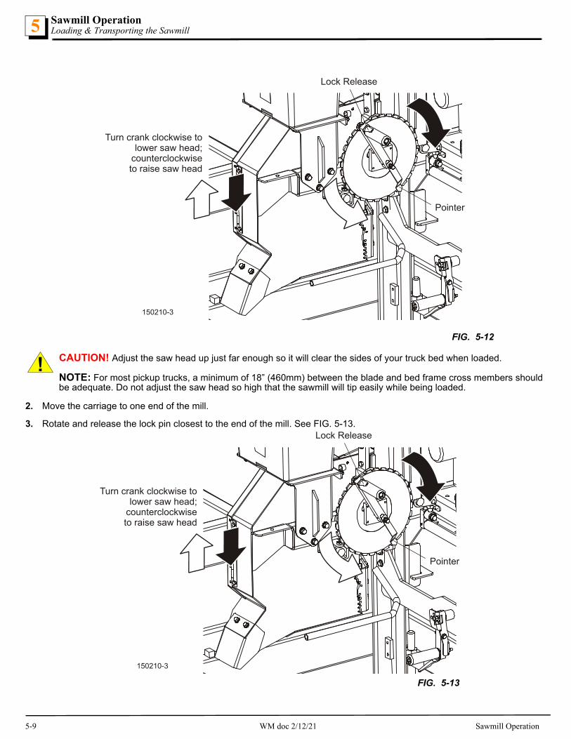
CAUTION! Adjust the saw head up just far enough so it will clear the sides of your truck bed when loaded.
NOTE: For most pickup trucks, a minimum of 18” (460mm) between the blade and bed frame cross members should be adequate. Do not adjust the saw head so high that the sawmill will tip easily while being loaded.
2. Move the carriage to one end of the mill.
3. Rotate and release the lock pin closest to the end of the mill. See FIG. 5-13.
FIG. 5-12
150210-3
Turn crank clockwise tolower saw head;
counterclockwiseto raise saw head
Lock Release
Pointer
150210-3
Turn crank clockwise tolower saw head;
counterclockwiseto raise saw head
Lock Release
Pointer
FIG. 5-13
5-9 WM doc 2/12/21 Sawmill Operation

Sawmill OperationLoading & Transporting the Sawmill 5
CAUTION! Be sure the lock pin engages the hole in the bed frame to secure the saw carriage in place. The other lock pin remains in the operation position.
4. Remove the tailgate from your truck to eliminate the possibility of damage and/or injury,
5. Position the bed of the truck at the end of the frame opposite the carriage.
WARNING! Keep all persons out of the area between the frame rails while loading and unloading the sawmill. Failure to follow this may result in serious injury or death.
Do not lift the sawmill onto the truck using ropes, cables, or chains, etc.; the sawmill can easily rotate and tip over when lifted. Failure to follow this may result in serious injury or death.
6. Position two people (for lifting) about two feet inward from the end of the frame.
7. As they lift the frame, the third person should back the truck slowly under the sawmill until the end of the frame is resting firmly on the bed of the truck.
NOTICE The operator side is heavier than the opposite side.
8. Position two people on either side of the saw head to hold the sawhead while a third person pulls and rotates (releases) the lock pin from the locked position to the operation position.
9. Push the saw carriage up the bed frame to the opposite side of the bed frame (on the truck).
NOTE: More people may be required to help push as the saw head gets more difficult to push up the incline.
10. Engage the lock pin at the end of the sawmill to secure the carriage. See FIG. 5-14.
CAUTION! Be sure the lock pin engages the hole in the bed frame to secure the saw carriage in place. The other lock pin remains in the operation position.
11. Use three or more people to lift the end of the mill still on the ground and slide the sawmill into the truck bed.
12. Secure the sawmill to the truck bed to prevent the sawmill from shifting while it is being transported. If the sawmill extends beyond the truck bed, attach a red warning flag to the end of the sawmill.
FIG. 5-14
150210-3
Turn crank clockwise tolower saw head;
counterclockwiseto raise saw head
Lock Release
Pointer
Sawmill Operation WM doc 2/12/21 5-10

MaintenanceWear Life6
SECTION 6 MAINTENANCE
This section lists the maintenance procedures that need to be performed.
See the Maintenance chart located after this section for a complete list of maintenance procedures and intervals. Keep a log of machine maintenance by recording in the machine hours and the date you perform each procedure.
Refer to option and engine manuals for other maintenance procedures.
6.1 Wear Life
Table 6-1 lists estimated life expectancy of common replacement parts if proper maintenance and operation procedures are fol-lowed. Due to the many variables which exist during sawmill operation, actual part life may vary significantly. This information is provided so that you may plan ahead in ordering replacement parts.
6.2 Blade Guides
WARNING! Turn the key switch to the OFF (#0) position and remove the key prior to performing service near moving parts such as blades, pulleys, motors, belts, or chains.
1. Check the rollers for performance and wear every blade change. Make sure the rollers are clean and spinning freely. If not, replace them. Replace any rollers which have worn smooth or have become cone shaped.
6.3 Sawdust Removal
AS REQUIRED
WARNING! Turn the key switch to the OFF (#0) position and remove the key prior to performing service near moving parts such as blades, pulleys, motors, belts, or chains.
1. Remove the excess sawdust from the blade wheel housings and sawdust chute every blade change.
2. Ensure the steel fingers inside the sawdust chute are in place and in working order.
The steel fingers prevent a broken blades or other objects from becoming a projectile when exiting the sawdust chute.
3. Remove sawdust buildup from rope feed pulleys and up/down chain sprockets as necessary.
6.4 Carriage Track, Wiper & Scrapers
WARNING! Before performing service near moving parts such as blades, pulleys, motors, belts and chains, first turn the key switch to the OFF (#0) position and remove the key.
Properly maintaining the sawmill carriage track is critical in preventing corrosion that can cause pitting and scaling on the rail surfaces. Pitted and scaled surfaces can, in turn, cause rough cuts or jerky feed movement.
EVERY 8 HOURS
1. Clean track rails to remove any sawdust and sap buildup every eight hours of operation.
Use a light-grade sandpaper or emery cloth to sand off any rust or other adhering particles from the rails.
CAUTION! Keep track rails free of rust. Formation of rust on the track rail in the areas where the cam bearings roll can cause rapid deterioration of the track rail's surface.
Lubricate the rails by wiping them with Dexron III ATF transmission fluid. Lubrication will help protect the rails from corrosive elements such as acid rain and/or moisture from nearby bodies of saltwater (if applicable). This lubrication is essential to main-tain the integrity of the track rails and track rollers and to achieve long service life.
Part Description Estimated Life
B57 Blade Wheel Belts 400 hours
Blade Guide Rollers 1000 hours
Drive Belt 1250 hours
TABLE 6-1
6-1 WM doc 2/12/21 Maintenance

MaintenanceCarriage Track, Wiper & Scrapers 6
EVERY 25 HOURS
2. Remove sawdust from the track roller housings and lubricate the felt track wipers every twenty-five hours of operation.
3. Remove the track roller housing covers and brush any sawdust buildup from the housings.
4. Clean and lubricate the felt track wipers. Unbolt the middle track cover and idle track wipers, remove from the sawmill and remove any sawdust buildup. Soak the felt wipers with Dexron III transmission fluid.
AS REQUIRED
5. Check the track scrapers as needed. Make sure the scrapers fit firmly against the rail. If a track scraper needs to be adjusted, loosen the screw, push the scraper downward until it fits firmly against the rail, and retighten the screw. See FIG. 6-1 or 6-2.
FIG. 6-1 LT15
FIG. 6-2 LT15 WIDE ONLY
150210-22B
Rev. A1.00 - E7.03
Track roller housingMiddle track cover
Track roller housing
Idle track wipers
Track wipers
Track roller housing Middle track cover
Track roller housingTrack wipers
Maintenance WM doc 2/12/21 6-2
MaintenanceVertical Mast Rails6
6.5 Vertical Mast Rails
WARNING! Before performing service near moving parts such as blades, pulleys, motors, belts and chains, first turn the key switch to the OFF (#0) position and remove the key.
EVERY 50 HOURS
Clean the vertical mast rails every 50 hours of operation.
CAUTION! Do not use grease on the mast rails; it will collect sawdust.
6.6 Miscellaneous
WARNING! Before performing service near moving parts such as blades, pulleys, motors, belts and chains, first turn the key switch to the OFF (#0) position and remove the key.
EVERY 50 HOURS
1. Oil all chains with Dexron III ATF every fifty hours of operation.
CAUTION! Do not use chain lube. It causes sawdust buildup in chain links.
2. Grease the clamps and side support pivots with a NLGI No. 2 grade lithium grease every fifty hours of operation.
3. Check the mill alignment every setup (See Section SECTION 7).
4. Make sure all safety warning decals are readable. Remove sawdust and dirt. Replace any damaged or unreadable decals immediately. Order decals from your Customer Service Representative.
6.7 Blade Wheel Belts
WARNING! Before performing service near moving parts such as blades, pulleys, motors, belts and chains, first turn the key switch to the OFF (#0) position and remove the key.
EVERY 50 HOURS
Rotate the blade wheel belts and check them for wear. Rotating the belts every 50 hours will provide longer belt life. Replace belts as necessary. Use only B57 belts supplied by Wood-Mizer.
6.8 Drive Belt Adjustment
WARNING! Disconnect and lockout power before performing any service to the electrical system. For battery-pow-ered equipment, disconnect the negative battery terminal cable.Failure to follow this may result in injury and/or electri-cal system damage.
Before performing service near moving parts such as blades, pulleys, motors, belts and chains, first turn the key switch to the OFF (#0) position and remove the key.
Do not adjust the engine drive belts or belt support bracket with the engine running.
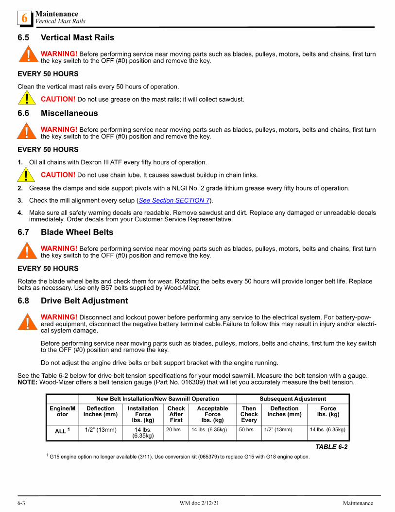
See the Table 6-2 below for drive belt tension specifications for your model sawmill. Measure the belt tension with a gauge. NOTE: Wood-Mizer offers a belt tension gauge (Part No. 016309) that will let you accurately measure the belt tension.
New Belt Installation/New Sawmill Operation Subsequent Adjustment
Engine/Motor
DeflectionInches (mm)
Installation Force
lbs. (kg)
Check After First
Acceptable Force
lbs. (kg)
Then Check Every
DeflectionInches (mm)
Forcelbs. (kg)
ALL 1
1 G15 engine option no longer available (3/11). Use conversion kit (065379) to replace G15 with G18 engine option.
1/2” (13mm) 14 lbs. (6.35kg)
20 hrs 14 lbs. (6.35kg) 50 hrs 1/2” (13mm) 14 lbs. (6.35kg)
TABLE 6-2
6-3 WM doc 2/12/21 Maintenance

MaintenanceUp/Down System 6
ADJUST THE DRIVE BELT TENSION
1. Loosen the drive belt jam and hex nuts. Turn the jam nut counterclockwise (as viewed from the top) to tighten the belt.
2. GAS OPTION ONLY: After tensioning the drive belt, check the throttle linkage and adjust if necessary.
NOTE: With the clutch handle engaged, the throttle linkage should move the throttle lever to full speed. To adjust, loosen the throttle linkage adjustment screw and slide the throttle linkage down. Retighten the screw.
Periodically check the drive belt for wear. Replace any damaged or worn belts as needed.
ADJUST THE DRIVE BELT SUPPORT (ENGINES G19, G25, D19, AND D17)
The drive belt support is designed to extend belt life. The bracket should be adjusted to NOT touch the drive belt when the clutch handle is engaged (down position), AND to hold the drive belt away from the engine pulley when the clutch handle is disengaged (up position).
1. Adjust the drive belt support as required.
1). Loosen the adjustment bolts.
2). Position the bracket so that the prong is close to, but doesnot touch, the drive belt with the clutch handle engaged.
3). Retighten the adjustment bolts 25-27 pound feet (34-37 Nm).
CAUTION! Do not over-tighten the drive belt. Damage to the engine may result.
6.9 Up/Down System
WARNING! Before performing service near moving parts such as blades, pulleys, motors, belts and chains, first turn the key switch to the OFF (#0) position and remove the key.
FIG. 6-3
150210-13C
1/2“ (13 mm)
Turn jam nut clockwiseto loosen drive belt
Throttle LinkageAdjustment
Belt Tension Gauge
Hex Nut
After 4/15
150256-08
Drive BeltSupport Bracket
FIG. 6-4
Maintenance WM doc 2/12/21 6-4

MaintenanceUp/Down System6
ADJUST THE UP/DOWN CHAIN TENSION AS NEEDED.
1. Measure chain tension with the head all the way to the top of the vertical mast.
WARNING! Always secure the saw head with a chain with at least 1900 lbs. working load capacity before adjusting the up/down chain. The cutting head may fall, causing severe injury or death.
2. Locate the chain adjusting bolt at the bottom of the mast.
3. Loosen the nut on the sprocket bolt and move the sprocket down until there is about 1" (2.5 cm) total deflection in the cen-ter of the chain with a 5 lb. (2.3 Kg) deflection force.
A chain tension adjustment bracket/bolt is provided on the sprocket assembly. Loosen the jam nut and tighten the adjust-ment bolt to pull the sprocket down and tension the chain. Retighten the jam nut and sprocket nut after tensioning the chain. See FIG. 6-5. .
LIFT ASSIST CABLES
Check the up/down lift assist cables daily or between shifts for cuts, cracked coating, fraying, defective cables, or other haz-ards. Replace as necessary.
LIFT ASSIST
WARNING! Always secure the saw head with a 5/16" (8mm) chain with at least 1900 lbs. (860Kg) working load capacity before servicing the up/down assist. The cutting head may fall, causing severe injury or death.
Release pressure from the up/down assist prior to performing any service to the assembly. Failure to follow this may result in the assembly flying apart, causing injury or damage to the equipment.
The up/down system is equipped with a gas spring assist mecha-nism to provide improved speed and performance. The saw head must be secured and tension released from the assist assembly before performing any maintenance to assist components.
1. Raise the saw head all the way to the top of the mast and secure with a chain. See FIG. 6-6.
2. Locate the up/down assist tension assembly.
3. Loosen (but do not remove) the tension adjustment bolt. Remove the cable from the top pulley and remove the four mounting bolts at the top of the assist assembly. See FIG. 6-7.
150210-23
Tighten adjustmentnut to tension chain
Loosen Mounting Bolt FIG. 6-5
Up/Down AssistTension AdjustmentBolt
150135
FIG. 6-6
Remove cablefrom upper pulley
Upper mountingbolts (4)
150135-1FIG. 6-7
6-5 WM doc 2/12/21 Maintenance

MaintenanceCharging The Battery 6
WARNING! Do not disassemble the gas spring cylinders; the gas spring cylinders are pressurized.
4. Lift the top assist housing to access the gas spring cylinders. The cylin-ders can be unthreaded from the bottom mounts without removing the bot-tom housing from the mast. Do not disassemble the gas spring cylinders.
5. When service is complete, reinstall the assist assembly in the reverse order of the disassembly procedure. Tighten the tension bolt all the way.
Lubricate the up/down crank handle bearings every 200 hours with a NLGI No. 2 grade lithium grease. Apply the grease to the fitting on the handle bracket tube. See FIG. 6-9.
6.10 Charging The Battery
DANGER! Batteries expel explosive gases. Keep sparks, flames, burning cigarettes, or other ignition sources away at all times.
WARNING! Battery posts, terminals and related accessories contain lead and lead compounds, chemicals known to the State of California to cause cancer and reproductive harm. Wash hands after handling.
Wear safety goggles and a face shield when working near batteries.
Charge the battery in a well ventilated area.
Do not attempt to charge a frozen battery.
Use extreme care to avoid spilling or splashing electrolyte (which is dilute sulfuric acid) as it can destroy clothing and burn the skin.:
EMERGENCY TREATMENT FOR CONTACT WITH BATTERY COMPONENTS (LEAD/SULFURIC ACID) per SDS (Safety Data Sheet)
EYE CONTACT Sulfuric Acid and Lead: Flush eyes immediately with large amounts of water for at least 15 minutes while lifting lids. Seek immedi-ate medical attention if eyes have been exposed directly to acid.
SKIN CONTACT Sulfuric Acid: Flush affected area(s) with large amounts of water using deluge emergency shower, if available, shower for at least 15 minutes. Remove contaminated clothing, including shoes. If symptoms persist, seek medical attention. Wash contaminated clothing before reuse. Discard contaminated shoes.Lead: Wash immediately with soap and water.
150210-6
Up/Down Chain
FIG. 6-8
Up/Down CrankHandle Grease Fitting
150139-2
FIG. 6-9
Maintenance WM doc 2/12/21 6-6

MaintenanceCharging The Battery6
CAUTION! Do not overcharge the battery. Overcharging may reduce the overall service life of the battery.
Be sure the battery is fully charged before transporting the sawmill. If the battery is not fully charged, excessive vibra-tion could reduce the overall service life of the battery.
1. Turn the key to the OFF (#0) position and remove the key.
2. Remove the battery box lid.
3. Clean the battery terminals if necessary.
4. Connect the positive charger/jumper cable directly to the positive battery terminal.
5. Connect the negative charger/jumper cable to a grounded metal surface.
6. Follow the instructions supplied with your specific battery charger.
NOTICE Be careful not to overcharge the battery, especially when using a high-rate or “boost” charger (40 amps or higher). These are intended to quickly charge a good battery that is discharged. They are not intended for unattended or long-term charging.
7. After the battery is completely recharged, remove the negative charger/jumper cable from ground.
8. Remove the positive charger/jumper cable from the battery.
Replace the battery box lid.
INGESTION Sulfuric Acid: Administer large amounts of water. Do NOT induce vomiting or aspiration into the lungs may occur and can cause permanent injury or death; consult physician.
INHALATION Sulfuric Acid: Remove to fresh air immediately. If not breathing, give artificial respiration. If breathing is difficult, give oxygen. Con-sult a physician.Lead: Remove from exposure, gargle, wash nose and lips; consult physician.
EMERGENCY TREATMENT FOR CONTACT WITH BATTERY COMPONENTS (LEAD/SULFURIC ACID) per SDS (Safety Data Sheet)
6-7 WM doc 2/12/21 Maintenance

Maintenance chart 6
WM doc 2/12/21 6-1
6.11 Maintenance chart
MAINTENANCE LOG(Check Engine And Option Manuals for additional mainte-
nance procedures)
MANUALREFERENCE
MAINTENANCE INTERVAL
Clean sawdust from ,battery box lid & track cover See Section 5.3 8 hours
Clean and lubricate top/bottom track See Section 5.4 8 hours
Check blade guide roller wear See Section 5.2 8 hoursEvery blade change
Remove excess sawdust from blade wheel housings and sawdust chute
See Section 5.3 8 hoursEvery blade change
Inspect fingers inside sawdust chute See Section 5.3 8 hoursEvery blade change
Remove sawdust from upper track roller housings See Section 5.4 25 hours
Clean & lube mast rails See Section 5.5 50 hours
Grease pivot points and bearings/oil chains See Section 5.6 50 hours
Rotate drive/idle blade wheel belts/check for wear See Section 5.7 50 hours
Check belt tensions See Section 5.8 50 hours
Check up/down chain tension See Section 5.10 50 hours
Lubricate Up/Down Crank Handle Bearings See Section 5.10 200 hours
Re-check belt tensions See Section 5.8 200 hours

Troubleshooting GuideSawing Problems7
7-1 WM doc 2/12/21 Troubleshooting Guide
SECTION 7 TROUBLESHOOTING GUIDE
7.1 Sawing Problems
WARNING! Before performing service near moving parts such as blades, pulleys, motors, belts and chains, first turn the key switch to the OFF (#0) position and remove the key.
PROBLEM CAUSE SOLUTION
Blades Dull Quickly Dirty logs Clean or debark logs, especially on entry side of the cut
When grinding teeth, heating too much and causing teeth to soften
Grind just enough metal to restore sharpness. Use water/coolant while sharpening blade
Poor sharpening techniques Make sure the tip is being sharpened com-pletely: Read the instructions with your blade sharpening equipment carefully
Blades Break Prematurely Poor sharpening techniques Read the instructions with your blade sharpen-ing equipment carefully
Rubber belts on blade wheels worn to a point that blade contacts metal pulley - look for shiny spots on edge of wheels
Change blade wheel belts (B-57)
Tension too tight Tension blade to recommended specifications
Blade Does Not Track Right on Drive Wheel
Cant adjustment is incorrect Readjust
Blade Guides Do Not Spin While Cutting
Frozen bearings Replace bearings
Drive Belts Wear Prematurely or Jump
Engine/motor drive pulleys out of alignment Align pulleys
Boards Thick Or Thin On Ends Or Middle Of Board.
Stress in log which causes log to not lay flat on the bed.
After log has been squared, take equal cuts off opposing sides. Take a board off the top. Turn the log 180 degrees. Take a board off. Repeat, keeping the heart in the middle of the cant, and making it your last cut.
Set in teeth. Resharpen and reset blade.
Bed rails misaligned. Realign sawmill.
Height Adjustment Jumps or Stut-ters When Moving Up or Down.
Up/down chain improperly adjusted. Adjust up/down chain.
Vertical wear pads are too tight. Adjust pads.
Lumber Is Not Square Vertical side supports not square to bed Adjust side supports.
Blade not parallel to bed rails Adjust bed rails parallel to blade.
Sawdust or bark between cant and bed rails Remove particles
Tooth set problems Resharpen and reset blade
Sawdust Builds Up On Track Excessive oiling Do not oil track
Track wipers worn Adjust wipers to firmly contact track
Track is sticky Clean track with solvent and apply silicone spray
Wavy Cuts Excessive feed Slow feed rate
Improperly sharpened blade (This will be the problem 99% of the time!)
Resharpen blade, following the sharpener’s instructions carefully
Blade guides improperly adjusted Adjust blade guides.
Sap buildup on blade Use Water Lube.
Tooth set problem Resharpen and reset blade
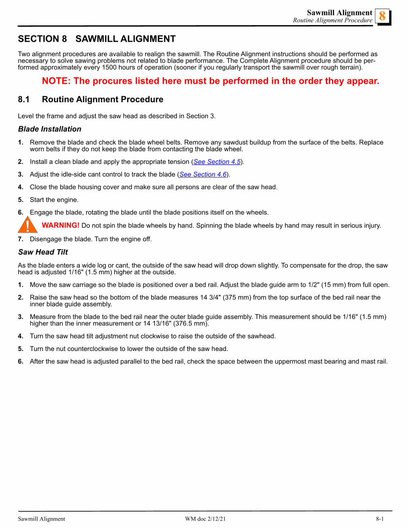
Sawmill AlignmentRoutine Alignment Procedure 8
SECTION 8 SAWMILL ALIGNMENT
Two alignment procedures are available to realign the sawmill. The Routine Alignment instructions should be performed as necessary to solve sawing problems not related to blade performance. The Complete Alignment procedure should be per-formed approximately every 1500 hours of operation (sooner if you regularly transport the sawmill over rough terrain).
NOTE: The procures listed here must be performed in the order they appear.
8.1 Routine Alignment Procedure
Level the frame and adjust the saw head as described in Section 3.
Blade Installation
1. Remove the blade and check the blade wheel belts. Remove any sawdust buildup from the surface of the belts. Replace worn belts if they do not keep the blade from contacting the blade wheel.
2. Install a clean blade and apply the appropriate tension (See Section 4.5).
3. Adjust the idle-side cant control to track the blade (See Section 4.6).
4. Close the blade housing cover and make sure all persons are clear of the saw head.
5. Start the engine.
6. Engage the blade, rotating the blade until the blade positions itself on the wheels.
WARNING! Do not spin the blade wheels by hand. Spinning the blade wheels by hand may result in serious injury.
7. Disengage the blade. Turn the engine off.
Saw Head Tilt
As the blade enters a wide log or cant, the outside of the saw head will drop down slightly. To compensate for the drop, the saw head is adjusted 1/16" (1.5 mm) higher at the outside.
1. Move the saw carriage so the blade is positioned over a bed rail. Adjust the blade guide arm to 1/2" (15 mm) from full open.
2. Raise the saw head so the bottom of the blade measures 14 3/4" (375 mm) from the top surface of the bed rail near the inner blade guide assembly.
3. Measure from the blade to the bed rail near the outer blade guide assembly. This measurement should be 1/16" (1.5 mm) higher than the inner measurement or 14 13/16" (376.5 mm).
4. Turn the saw head tilt adjustment nut clockwise to raise the outside of the sawhead.
5. Turn the nut counterclockwise to lower the outside of the saw head.
6. After the saw head is adjusted parallel to the bed rail, check the space between the uppermost mast bearing and mast rail.
Sawmill Alignment WM doc 2/12/21 8-1

Sawmill AlignmentBlade Guide Arm Alignment8
7. Adjust as necessary so the space is 1/32” - 1/16” (0.8 - 1.6mm).
Blade Guide Arm Alignment
The blade guide arm moves the outer blade guide in and out. If the arm becomes loose, the blade guide will not deflect the blade properly, causing inaccurate cuts. A loose blade guide arm can also cause blade vibration.
1. Adjust the blade guide arm out to 1/2" (13 mm) from fully open.See FIG. 8-2.
2. Use the inside top and bottom screws to adjust the arm up until the slide pad touches the saw head brace tube.
3. Tighten the jam nuts.
4. Adjust the blade guide arm in all the way toward the other blade guide.
5. Use the outside top and bottom screws to adjust the arm up until the slide pad touches the saw head brace tube.
6. Tighten the jam nuts.
NOTE: When adjusting the blade guide arm screws, be careful not to tighten the screws too much or put the arm in a bind. Operate the blade guide arm to ensure the arm moves easily in and out.
FIG. 8-1
150125-10
Turn Tilt Adjustment NutClockwise to raise outside ofsaw head; Counterclockwiseto lower outside of saw head
Loosen Bearing NutAnd Adjust Space fromMast to 1/32" - 1/16" (0.8 - 1.6mm)
150210-7
Adjust outside topand bottom screwswith arm closed
Adjust inside topand bottom screwswith arm open
FIG. 8-2
8-2 WM doc 2/12/21 Sawmill Alignment

Sawmill AlignmentBlade Guide Vertical Tilt Alignment 8
7. With the blade guide arm still all the way in toward the other blade guide, tighten all the side screws until they touch the arm. See FIG. 8-3.
8. Back the screws off 1/4 turn and tighten the jam nuts.
9. Measure the distance between the blade guide arm and back edge of the blade.
10. Adjust the appropriate side screws on the blade guide arm housing so the arm is measures the same distance from the blade at both ends of the arm.
11. To move the blade guide end of the arm toward the front of the sawmill, loosen jam nuts on the front inside screw and the rear outside screw.
12. Turn the screws counterclockwise one full turn and tighten the jam nuts.
13. Loosen the jam nuts on the front outside screw and the rear inside screw.
14. Turn the screws clockwise until they touch the arm, back off 1/4” turn, and tighten the jam nuts.
15. To move the blade guide end of the arm toward the rear of the sawmill, loosen jam nuts on the front outside screw and the rear inside screw.
16. Turn the screws counterclockwise one full turn and tighten the jam nuts.
17. Loosen the jam nuts on the front inside screw and the rear outside screw.
18. Turn the screws clockwise until they touch the arm, back off 1/4” turn, and tighten the jam nuts.
Blade Guide Vertical Tilt Alignment
The blade guides should be adjusted properly in the vertical plane. If the blade guides are tilted vertically, the blade will try to travel in the tilted direction.
A Blade Guide Alignment Tool (BGAT) is provided to help you measure the vertical tilt of the blade.
1. Open the adjustable blade guide arm 1/2" (13 mm) from full open.
2. Clip the alignment tool on the blade. See FIG. 8-4.
3. Position the tool close to the outer blade guide assembly.
Ensure the tool does not rest on a tooth or burr, and is lying flat against the bottom of the blade.
4. Move the carriage so that the front end of the tool is positioned above the bed rail. Measure the distance from the bed rail to the bottom edge of the tool.
5. Move the carriage so that the back end of the tool is positioned above the bed rail. Measure the distance from the bed rail to the bottom edge of the tool.
FIG. 8-3
150036B
Blade Guide Arm Parallel to Blade
Adjust side screws tochange arm angle
SM0069B
Clip tool to blade
FIG. 8-4
Sawmill Alignment WM doc 2/12/21 8-3

Sawmill AlignmentBlade Guide Horizontal Tilt Adjustment8
6. If the measurement from the tool to the bed rail is not equal within 1/32" (.75 mm), adjust the vertical tilt of the outer blade guide roller.
7. Loosen one set screw at the side of the blade guide assembly. See FIG. 8-5.
8. Loosen the jam nuts on the top and bottom vertical tilt adjustment screws.
1). To tilt the roller up, loosen the bottom screw and tightentop screw.
2). Reverse this to tilt down.
3). Tighten the jam nuts and recheck the tilt of the blade.
9. Move the blade guide alignment tool close to the inner blade guide roller assembly and repeat the above steps.
10. Adjust the vertical tilt of the inner blade guide if necessary.
Blade Guide Horizontal Tilt Adjustment
If the blade guides are tilted in the wrong direction horizontally, the back of the blade may contact the flange as the roller is spin-ning down, causing it to push the blade away from the guide roller.
1. Remove the blade guide alignment tool from the blade and adjust the blade guide arm halfway in.
2. Remove the clip from the blade guide alignment tool and place the tool against the face of the outer blade guide roller. See FIG. 6-6.
3. Measure between the back edge of the blade and the tool at the end closest to the inner blade guide ("B").
4. Measure between the back edge of the blade and the other end of the tool ("A").
The roller should be tilted slightly to the left (’A’ 1/8" [3 mm] less than ’B’ ±1/8" [3 mm]).
5. Loosen the jam nuts on the horizontal tilt adjustment screws. See FIG. 6-7.
1). To tilt the roller left, loosen the right screw and tighten leftscrew.
2). Reverse to tilt right.
3). Tighten the jam nuts and recheck the tilt of the blade.
6. Repeat the above steps for the inner blade guide roller assembly.
NOTE: Once the blade guides have been adjusted, any cutting variances are most likely caused by the blade.
Blade Guide Flange Spacing
Each blade guide must be adjusted so the roller flange is the correct distance from the back edge of the blade. If the flange is too close to or too far from the blade, the sawmill will not cut accurately.
HINT: When adjusting blade guide spacing, loosen the top set screw and one side set screw only. This will ensure horizontal and vertical tilt adjustments are maintained when the adjustment screws are retightened.
SM0310-1
Adjust screws downto tilt roller up; Adjustscrews up to tilt rollerdown
Bottom Vertical TiltAdjustment Screw
Top Vertical TiltAdjustment Screw
FIG. 8-5
3H0802-5B
A B
Blade GuideAlignment Tool
FIG. 8-6
3H0802-9
Adjust screws rightto tilt roller left; Adjustscrews left to tilt rollerright
Horizontal TiltAdjustment Screws
FIG. 8-7
8-4 WM doc 2/12/21 Sawmill Alignment

Sawmill AlignmentSide Support Alignment 8
1. Measure the distance between the flange on the outer blade guide roller to the back edge of the blade. This distance should measure 1/8" (3.0 mm). Adjust the roller back or forward if necessary.
2. Loosen the top and one side screw shown. See FIG. 8-8.
3. Tap the blade guide forward or backward until properly posi-tioned.
4. Retighten the screws and jam nuts.
5. Measure the distance between the flange on the inner blade guide roller to the back edge of the blade.
This distance should measure 1/16" (1.5 mm). Adjust the roller back or forward if necessary.
Side Support Alignment
Logs and boards are clamped against the side supports when sawing. The sides supports must be square to the bed to ensure square lumber.
1. Place a flat board across the bed rails. Swing a side support up so that it is vertical.
2. Pull back at the top of the support to eliminate slack as if a log were being clamped against it.
3. Place a square against the face of the side support. The side support should be square or slightly tilted forward 1/32" (0.8 mm). Adjust the vertical tilt of the side support if necessary.
Loosen the top adjustment bolt, adjust the side support, and retighten the bolt.Turn the adjustment bolt counterclockwise to tilt the top of the side support forward.
4. Repeat the vertical check for the remaining side supports and adjust as necessary.
FIG. 8-9
3H0802-6
Loosen top andone side adjustment
screw
1/16” (Inner Blade Guide)1/8” (Outer Blade Guide)
FIG. 8-8
Side SupportAdjustment Bolt
150039
Sawmill Alignment WM doc 2/12/21 8-5

Sawmill AlignmentBlade Height Scale Adjustment8
Blade Height Scale Adjustment
After the entire sawmill has been aligned and all adjustments made, check that the blade height scale indicates the true distance from the blade to the bed rails.
1. Move the saw carriage so the blade is positioned directly above one of the bed rails.
2. Measure from the bottom edge on a down-set tooth of the blade to the top of the bed rail, near the inner blade guide assembly.
3. View the blade height scale with eyes level with the indicator.
The scale should indicate the actual distance from the blade to the bed rail. Adjust the indicator if necessary.
4. Loosen the indicator bracket mounting nut.
5. Adjust the bracket up or down until the indicator is aligned with the correct mark on the scale (+0 -1/32 [0.8 mm]).
6. Retighten the indicator mounting nut.
Example: If the measurement from the down-set tooth of the blade to the bed rail was 14 3/4" (375 mm), make sure the indi-cator reads 14 3/4" (375 mm) on the scale.
8.2 \Complete Alignment Procedure
NOTE: The procures listed here must be performed in the order they appear
Frame Setup
Before performing the following alignment procedures, setup the mill on firm, level ground.
Level the frame and adjust the saw head as described in Section 4.1 Sawmill Setup.
Blade Installation
1. Remove the blade and replace the blade wheel belts. New blade wheel belts are required to perform the complete align-ment procedure.
2. Blow sawdust off of the blade guide assemblies. Remove sawdust from the blade housings.
3. Remove the blade guide assemblies.
NOTE: To remove the blade guide assemblies and maintain the tilt adjustments, only loosen one side screw and the top screw. Leaving the other side screw and bottom screw in position will insure you will return the rollers to their origi-nal tilt adjustment.
4. Adjust the outer blade guide arm in or out until the outer blade guide is approximately 24” from the inner blade guide.
5. Install a new blade and apply the appropriate tension (See Section 4.5).
6. Close the blade housing covers and make sure all persons are clear of the saw head.
7. Start the engine.
8. Engage the blade, rotating the blade until the blade positions itself on the wheels.
WARNING! Do not spin the blade wheels by hand. Spinning the blade wheels by hand may result in serious injury.
9. Disengage the blade. Turn the engine off.
150210-8
Loosen indicatorbracket mountingnut
FIG. 8-10
8-6 WM doc 2/12/21 Sawmill Alignment

Sawmill AlignmentSaw Head Tilt “Saw Head Tilt” on page 1 8
Saw Head Tilt “Saw Head Tilt” on page 1
Blade Wheel Alignment
The blade wheels should be adjusted so they are level in the vertical and horizontal planes. If the blade wheels are tilted up or down, the blade will want to travel in the tilted direction. If the blade wheels are tilted horizontally, the blade will not track prop-erly on the wheels.
Use the blade guide alignment tool to check the vertical alignment of each blade wheel.
1. Attach the tool to the blade near the inner blade guide mount.
Be sure the tool does not rest on a tooth or burr, and is lying flat against the bottom of the blade.
2. Move the saw carriage so the front end of the tool is positioned over the first bed rail.
3. Measure from the bottom of the tool to the top surface of the bed rail.
4. Move the saw carriage so the rear of the tool is positioned over the bed rail.
5. Again, measure from the bottom of the tool to the bed rail.
6. If the two measurements differ by more than 1/16" (1.5 mm), adjust the vertical tilt of the drive-side blade wheel.
7. Use the vertical adjustment screws to adjust the drive-side blade wheel. See FIG. 8-12.
1). To tilt the wheel down/up, loosen thetop/bottom adjustment screw one quarter turn.
2). Loosen the jam nut on the bottom/topadjustment screw and tighten the screw.
3). Tighten the top and bottom jam nuts.
8. Recheck the vertical tilt of the drive-side blade wheel with the blade guide alignment tool.
9. Readjust the blade wheel as necessary until the front and rear of the tool are the same distance from the bed rail (within 1/16" [1.5 mm]).
10. Remove the tool from the blade and reattach it near the outer blade guide assembly.
SM0069B
Clip tool to blade
FIG. 8-11
150210-14
Adjust vertical adjustment screwsdown to tilt drive-side blade wheel up;
Adjust screws up to tilt wheel down
Blade GuideAlignment Tool
FIG. 8-12
Sawmill Alignment WM doc 2/12/21 8-7

Sawmill AlignmentBlade Wheel Alignment8
11. Measure from the tool to the bed rail at both ends of the tool. If the measurements at the front and rear ends of the tool differ by more than 1/16" (1.5 mm), adjust the vertical tilt of the idle-side blade wheel.
12. Use the vertical adjustment screws to adjust the idle-side blade wheel.
1). TTo tilt the wheel down/up, loosen thetop/bottom adjustment screw one quarterturn.
2). Loosen the jam nut on the bottom/topadjustment screw and tighten the screw.
3). Tighten the top and bottom jam nuts.
13. Recheck the vertical tilt of the idle-side blade wheel with the blade guide alignment tool.
14. Readjust the blade wheel as necessary until the front and rear of the tool are the same dis-tance from the bed rail (within 1/16" [1.5 mm]).
15. Check the position of the blade on the idle-side blade wheel.
The horizontal tilt of the blade wheel should be adjusted so that the gullet of an 1-1/4" blade is 1/8" (3 mm) out from the front edge of the wheel (±1/32 [0.75 mm]).
16. Use the cant control adjustment to adjust the idle-side blade wheel.
FIG. 8-13
150210-9
Adjust vertical adjustmentscrews up to tilt idle-side
blade wheel down; Adjustscrews down to tilt wheel up
150060
1/8” (3.0 mm)± 1/32” (0.75 mm)
1 1/4”Blade
8-8 WM doc 2/12/21 Sawmill Alignment

Sawmill AlignmentBlade Guide Installation 8
17. If the blade is too far forward on the wheel, turn the cant control counterclockwise. Reverse if it is too far back on the wheel.
18. Check the position of the blade on the drive-side blade wheel.
The blade should be positioned on the wheel as described for the idle-side blade wheel.
19. Adjust the drive-side blade wheel if necessary.
20. Use the horizontal adjustment screws to adjust the drive-side blade wheel.
1). To move the blade back/forward on the wheel,loosen the right/left adjustment screw one quarter turn.
2). Loosen the jam nut on the left/right adjustmentscrew and tighten the screw.
3). Tighten the left and right jam nuts.
Blade Guide Installation
Each Wood-Mizer sawmill has two blade guide assemblies that help the blade maintain a straight cut. The two blade guide assemblies are positioned on the saw head to guide the blade on each side of the material being cut.
One blade guide assembly is mounted in a stationary position on the drive side of the saw head. This assembly is referred to as the "inner" blade guide assembly.
The other blade guide assembly is mounted on the idle side of the saw head. It is referred to as the "outer" assembly and is adjustable for various widths of materials to be processed.
FIG. 8-14
150210-10
Cant Control
150210-15
Adjust horizontal adjustment screwsleft to move blade out on wheel;
Adjust screws right to move blade in on wheelFIG. 8-15
Sawmill Alignment WM doc 2/12/21 8-9

Sawmill AlignmentBlade Guide Arm Alignment “Blade Guide Arm Alignment” on page 28
NOTE: Before installing the blade guide assemblies, remove the blade guide adjusting screws and apply a lubricating oil such as 10W30 or Dexron III to each screw. This will prevent the screws and threaded holes from corroding and make screw adjustments easier.
1. Install the outer blade guide assembly (with waterlube tube) to the mounting block on the blade guide arm. Posi-tion the assembly so the roller flange is 1/8" (3.0 mm) from the blade.
2. Install the inner blade guide assembly to the mounting block on the saw head. Position the assembly so the roller flange is 1/16" (1.5 mm) from the blade.
3. Tighten the two previously-loosened tilt adjustment screws to secure the blade guide assembly.
4. Loosen the top vertical adjustment jam nut and tighten the bottom vertical adjustment jam nut to adjust the blade guide roller up so it does not touch the blade.
Blade Guide Arm Alignment “Blade Guide Arm Alignment” on page 2
Blade Guide Deflection
Perform the following steps to achieve proper blade deflection with the blade guides.
1. Raise the saw head until the blade is 15" (375 mm) above a bed rail. Measure the actual distance with a tape from the top of the rail to the bottom of the blade.
2. Make sure the two vertical adjustment set screws are threaded into the blade guide shaft until they touch each other.
3. Loosen the bottom jam nut and tighten the top jam nut until the blade guide deflects the blade down until the bottom of the blade measures 14 3/4" (370 mm) from the bed rail.
4. Repeat for the other blade guide.
NOTE: Be sure that the blade guide deflector rod clears the blade on both guide assemblies. The rod on the outer guide assembly should be checked with the arm all the way in and all the way out.
NOTICE For the remainder of the Complete Alignment, refer back to Blade Guide Vertical Tilt Alignment “Blade Guide Vertical Tilt Alignment” on page 3 and continue on until the end of the Routine Alignment.
Tilt AdjustmentScrews (4)
3H0802-15
Blade GuideShaft CenteredIn Block
Top VerticalAdjustment Jam Nut
Bottom VerticalAdjustment Jam Nut
Roller Flange
FIG. 8-16
Top VerticalAdjustment Jam Nut
Bottom VerticalAdjustment Jam Nut
FIG. 8-17
8-10 WM doc 2/12/21 Sawmill Alignment