Embed Size (px)
Citation preview
Operator’s manual Matrix printer
T2280SprintPro
T2265SprintPro
®

Important InformationThis equipment generates and uses radio frequency energy andif not installed and used properly, that is, in accordance with themanufacturer’s instructions, may cause interference in radio andtelevision reception. It has been type tested and found to complywith the limits for class B computing devices in accordance withthe specification in subpart J of part 15 of FCC rules, which aredesigned to provide reasonable protection against such inter-ference in a residential installation. However, there is no guar-antee that interference will not occur in a partial installation. Ifthis equipment does cause interference to radio or televisionreception, which can be determined by turning the equipmentoff and on, the user is encouraged to try to correct the inter-ference by one or more of the following measures:
Reorient the receiving antenna,Relocate the peripheral away from the receiver,Move the peripheral away from the receiverPlug the peripheral into a different outlet, so that theperipheral and receiver are on different branch circuits
If necessary, the user should consult the dealer or an experi-enced radio/television technician for additional suggestions. Theuser may find the following booklet, prepared by the FederalCommunications Commission, helpful: “How to Identify andResolve Radio-TV Interference Problems”. This booklet is available from the U.S. Government PrintingOffice, Washington DC 20402 Stock No. 004.000.00345.4.WARNING: To comply with FCC regulations on electromagneticinterference for a class B computing device, the printer cablemust be shielded. To assure compliance with FCC regulationsfor a computing device, use a shielded interface cable with ametal shell connector. The use of cables not properly shieldedmay result in violating FCC regulations.This digital apparatus does not exceed the class B limits for radionoise emissions from digital apparatus as set out in the radiointerference regulations of the Canadian department of com-munications.This unit complies with DOC standard C108.8-M 1983
ATTENTION: Le présent appareil numérique n’ement pas debruits radioélectriques déspassant les limites applicables auxappareils numériques de la classe B prescrites dans le règlementsur le brouillage radio- électrique édicté par le minstère descommunications du Canada.
The paper used is made of raw materials treated with achlorine-free bleaching process.
WARNING For continued protection against risk of fire, replace only with same type and rating of fuse.Only trained and qualified personnel may open covers or remove parts that are not explicitly shown and described in the User Guide as being accessible to the operator.
ATTENTION Pour ne pas compromettre la protection contre les risques d’incendie, remplacer par un fusible de même type et de mêmescaractèristiques nominales.Seul un personnel qualifié et formé est habilité à démonter les sous-ensembles de la machine qui ne sont pas formellement indiqués dans le Manuel d’utilisation meme s’ils sont accessibles par l’opérateur.
This device fulfils the European standards requirements by complying with theDirective of the Commission dated May 3, 1989 (89/336/EEC) relating toelectromagnetic compatibility and the Directive dated February 19, 1973
(73/23/EEC) relating to low-voltage electrical equipment. Conformity with the above men-tioned Directives is indicated by the CE symbol attached to the device.
Note: Conformity may be affected by:
using interface cables not complying with the specifications
non-observance of important instructions in the operator’s manual
installing components not approved for this device by the manufacturer
unauthorized manipulation
Operator’s ManualQUICK START-UP
Table of contents
Table of contents
Introduction 2Symbols used 2Important safety instructions 2Using the Online-CD-ROM 3Contents of the Online CD-ROM 3Hardware requirements 3Troubleshooting 3
Printer at a glance 4
Installation 5Unpacking the printer 5Placing your printer 6Connecting the printer 7Switching on the printer 7
Control panel 8Online mode 8Offline mode 8Setup mode 8
Changing the ribbon cassette 9
Paper handling 14Changing the paper type 14Loading paper 15Fanfold paper 15Single sheets 17Paper transport 18Moving the paper to the tear position 19
Settings 20Setting the tear position 20Setting the first printing line (TOF) 21Setting the print head gap 22Selecting character density and font 23
Technical data 24Printer specifications 24Paper specifications 25
Accessories 26
EN
GLIS
H
Quick start-up Table of contents
1
Introduction This Operator’s Manual is intended as a quick introduction into working with the printer andalso to enable inexperienced users to operate the device properly. It describes the most import-ant functions of the printer and contains the essential information for your everyday workwith the printer. A more detailed description of the printer, its characteristic features, and fur-ther information is contained in the Reference Manual on the Online CD-ROM, which is in-serted at the back of this manual.
➤ Symbols used Important information is highlighted in this manual by two symbols.
CAUTION highlights information which must be observed in order to prevent injuries to theuser and damage to the printer.
NOTE highlights general or additional information about a specific topic.
➤ Important safety instructions
Read the following instructions thoroughly before starting up your printer in order to preventinjuries and avoid damage to the device.
Keep this Operator’s Manual in a place which is easily accessible at all times.
Place the printer on a solid base so that it cannot fall down to the ground.
Do not expose the printer to high temperatures or direct sunlight.
Keep all liquids away from the printer.
Protect the printer from shock, impact and vibration.
Be sure to connect the printer to a socket with the correct mains voltage.
The power supply cable may be damaged if the paper edges constantly chafe the insulatingsheath. The user must always ensure that there is sufficient distance between the power sup-ply cable and the paper.
Never carry out maintenance or repair work yourself. Always contact a qualified servicetechnician.
Whenever you want to disconnect the printer from the power supply, pull the plug out fromthe mains socket.
Additional safety instructions are provided at the relevant places in the text.
STOP
STOP
STOP
Ah ha!!
Introduction Quick start-up
2
➤ Using theOnline-CD-ROM
First install the Adobe Acrobat Reader on your hard disk, unless the program has alreadybeen installed. To install it, follow the steps described in the README file in the READERdirectory.
To start the online documentation, call the File Manager (Windows 3.1) or Explorer(Windows 95/98, Windows ME, Windows 2000, Windows NT4) and double click on theSTART.PDF file. Then follow the instructions and menus on the screen.
➤ Contents of the Online CD-ROM
The Online CD-ROM contains– the Reference Manual: A detailed description of the printer and its impressive features– Drivers: For Windows 3.1, Windows 95/98, Windows ME, Windows 2000, Windows NT4– Additional documentation: Programming instructions and descriptions of the available
options
If your CD-ROM is be defective or missing, please consult your dealer. The Online Documen-tation is also available as a hardcopy (at a cost) or can be downloaded via the Internet.
➤ Hardware requirements
Minimum hardware requirements: PC 486 MHS, quad-speed CD-ROM, 15" display screen,mouse.
➤ Troubleshooting The online documentation supplied on the CD-ROM contains detailed information on trouble-shooting.
EN
GLIS
H
Quick start-up Introduction
3
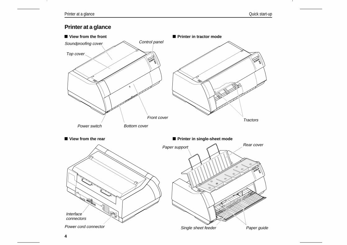
Printer at a glance
Top cover
Soundproofing cover Control panel
Power switch
Front cover
Bottom cover
Printer in tractor mode View from the front
Tractors
Printer in single-sheet mode View from the rear
Power cord connector
Interface connectors
Paper support
Single sheet feeder Paper guide
Rear cover
Printer at a glance Quick start-up
4
Installation
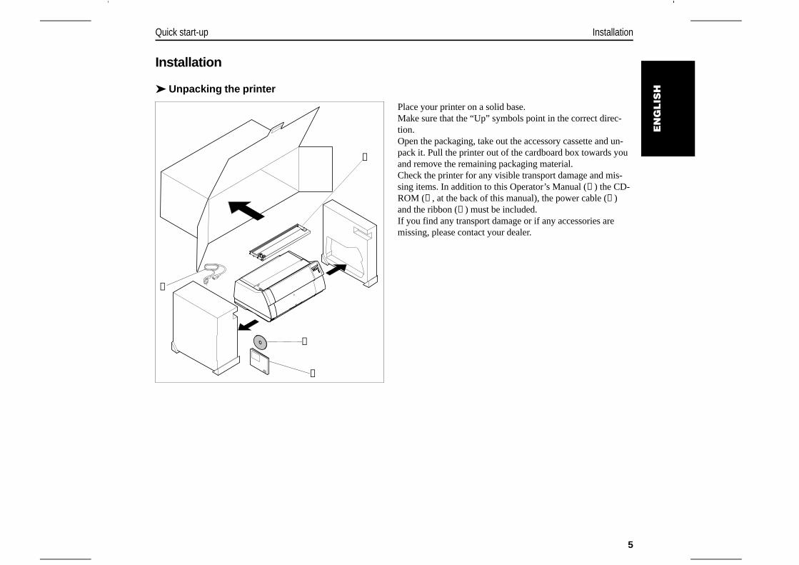
➤ Unpacking the printer
Place your printer on a solid base.Make sure that the “Up” symbols point in the correct direc-tion.Open the packaging, take out the accessory cassette and un-pack it. Pull the printer out of the cardboard box towards youand remove the remaining packaging material.Check the printer for any visible transport damage and mis-sing items. In addition to this Operator’s Manual (➀) the CD-ROM (➁, at the back of this manual), the power cable (➂)and the ribbon (➃) must be included.If you find any transport damage or if any accessories aremissing, please contact your dealer.
➀
➁
➂
➃
EN
GLIS
H
Quick start-up Installation
5
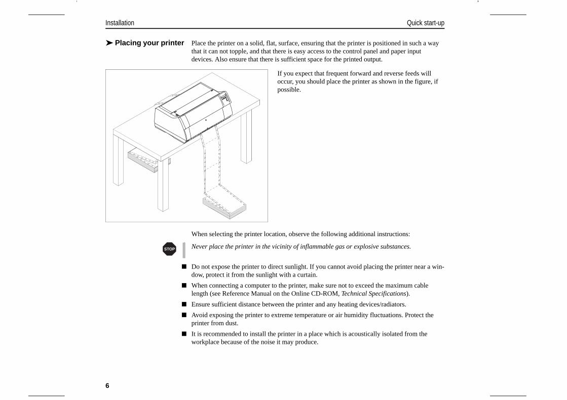
➤ Placing your printer Place the printer on a solid, flat, surface, ensuring that the printer is positioned in such a waythat it can not topple, and that there is easy access to the control panel and paper inputdevices. Also ensure that there is sufficient space for the printed output.
If you expect that frequent forward and reverse feeds willoccur, you should place the printer as shown in the figure, ifpossible.
When selecting the printer location, observe the following additional instructions:
Never place the printer in the vicinity of inflammable gas or explosive substances.
Do not expose the printer to direct sunlight. If you cannot avoid placing the printer near a win-dow, protect it from the sunlight with a curtain.
When connecting a computer to the printer, make sure not to exceed the maximum cablelength (see Reference Manual on the Online CD-ROM, Technical Specifications).
Ensure sufficient distance between the printer and any heating devices/radiators.
Avoid exposing the printer to extreme temperature or air humidity fluctuations. Protect theprinter from dust.
It is recommended to install the printer in a place which is acoustically isolated from theworkplace because of the noise it may produce.
STOP
Installation Quick start-up
6
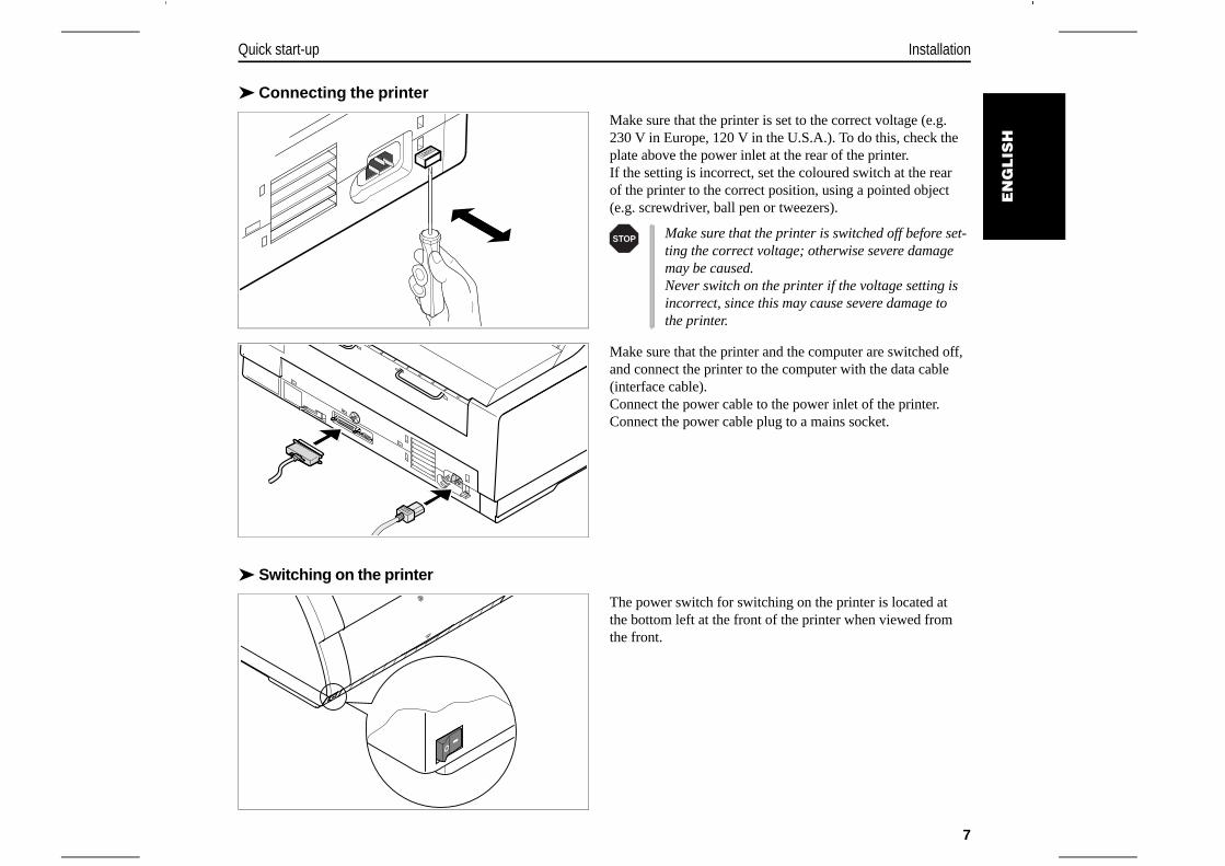
➤ Connecting the printer
Make sure that the printer is set to the correct voltage (e.g.230 V in Europe, 120 V in the U.S.A.). To do this, check theplate above the power inlet at the rear of the printer.If the setting is incorrect, set the coloured switch at the rearof the printer to the correct position, using a pointed object(e.g. screwdriver, ball pen or tweezers).
Make sure that the printer and the computer are switched off,and connect the printer to the computer with the data cable(interface cable).Connect the power cable to the power inlet of the printer.Connect the power cable plug to a mains socket.
➤ Switching on the printer
The power switch for switching on the printer is located atthe bottom left at the front of the printer when viewed fromthe front.
120V
Make sure that the printer is switched off before set-ting the correct voltage; otherwise severe damagemay be caused.Never switch on the printer if the voltage setting isincorrect, since this may cause severe damage tothe printer.
STOP
EN
GLIS
H
Quick start-up Installation
7
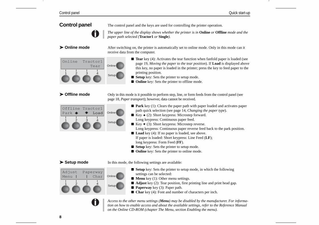
Control panel The control panel and the keys are used for controlling the printer operation.
The upper line of the display shows whether the printer is in Online or Offline mode and thepaper path selected (Tractor1 or Single).
➤ Online mode After switching on, the printer is automatically set to online mode. Only in this mode can itreceive data from the computer.
Tear key (4): Activates the tear function when fanfold paper is loaded (seepage 19, Moving the paper to the tear position). If Load is displayed abovethis key, no paper is loaded in the printer; press the key to feed paper to theprinting position.
Setup key: Sets the printer to setup mode. Online key: Sets the printer to offline mode.
➤ Offline mode Only in this mode is it possible to perform step, line, or form feeds from the control panel (seepage 18, Paper transport); however, data cannot be received.
Park key (1): Clears the paper path with paper loaded and activates paperpath quick selection (see page 14, Changing the paper type).
Key (2): Short keypress: Microstep forward.Long keypress: Continuous paper feed.
Key (3): Short keypress: Microstep reverse.Long keypress: Continuous paper reverse feed back to the park position.
Load key (4): If no paper is loaded, see above.If paper is loaded: Short keypress: Line Feed (LF); long keypress: Form Feed (FF).
Setup key: Sets the printer to setup mode. Online key: Sets the printer to online mode.
➤ Setup mode In this mode, the following settings are available:
Setup key: Sets the printer to setup mode, in which the followingsettings can be selected:
Menu key (1): Other menu settings. Adjust key (2): Tear position, first printing line and print head gap. Paperway key (3): Paper path. Char key (4): Font and number of characters per inch.
Access to the other menu settings (Menu) may be disabled by the manufacturer. For informa-tion on how to enable access and about the available settings, refer to the Reference Manualon the Online CD-ROM (chapter The Menu, section Enabling the menu).
Online Tractor1Tear Online
Setup21 3 4
Offline Tractor1Load Online
Setup
Park Load
21 3 4
Adjust PaperwayMenu Char Online
Setup21 3 4
Control panel Quick start-up
8

Changing theribbon cassette
Before opening the cover, make sure that the printer is switched on so that it can execute auto-matic preparations for ribbon changing (widening the print head gap).
Move the paper to the park position.Open the printer top cover.
Carefully slide the print head carriage to the left stop (viewedfrom the printer front).
The print head becomes hot during printing. Forthis reason, let it cool down before touching it.
STOP
EN
GLIS
H
Quick start-up Changing the ribbon cassette
9
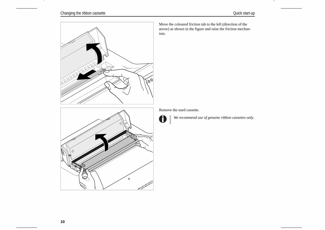
Move the coloured friction tab to the left (direction of thearrow) as shown in the figure and raise the friction mechan-ism.
Remove the used cassette.
We recommend use of genuine ribbon cassettes only.
Changing the ribbon cassette Quick start-up
10
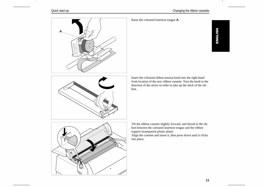
Raise the coloured insertion tongue A.
Insert the coloured ribbon tension knob into the right-handfront location of the new ribbon cassette. Turn the knob in thedirection of the arrow in order to take up the slack of the rib-bon.
Tilt the ribbon cassette slightly forward, and thread in the rib-bon between the coloured insertion tongue and the ribbonsupport (transparent plastic plate).Align the cassette and insert it, then press down until it clicksinto place.
A
EN
GLIS
H
Quick start-up Changing the ribbon cassette
11
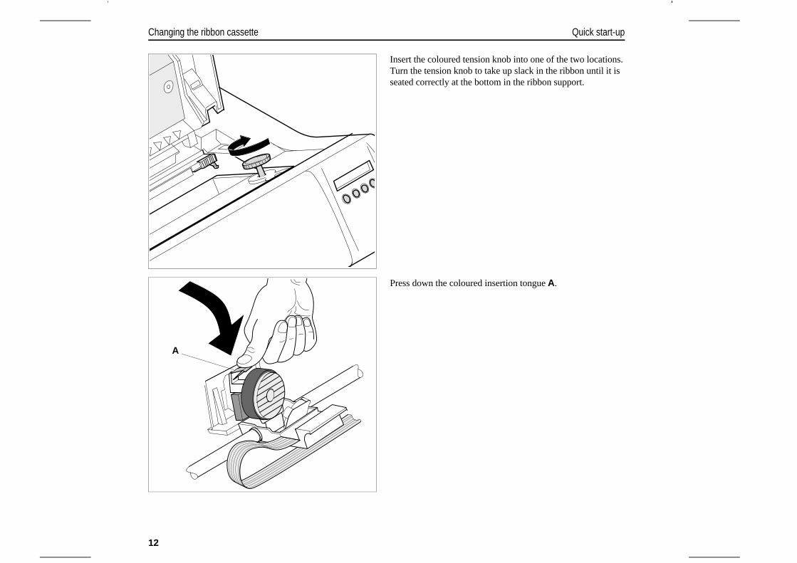
Insert the coloured tension knob into one of the two locations.Turn the tension knob to take up slack in the ribbon until it isseated correctly at the bottom in the ribbon support.
Press down the coloured insertion tongue A.
A
Changing the ribbon cassette Quick start-up
12
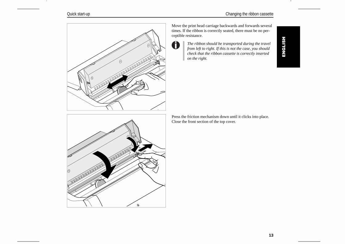
Move the print head carriage backwards and forwards severaltimes. If the ribbon is correctly seated, there must be no per-ceptible resistance.
Press the friction mechanism down until it clicks into place.Close the front section of the top cover.
The ribbon should be transported during the travelfrom left to right. If this is not the case, you shouldcheck that the ribbon cassette is correctly insertedon the right.
EN
GLIS
H
Quick start-up Changing the ribbon cassette
13
Paper handling This section describes how to set the paper type, load fanfold paper and single sheets, trans-port paper and move the paper to the tear position.
➤ Changing thepaper type
You can change the paper type either from an application program, by means of the paperpath quick selection feature or in the Setup menu. In this section, the quick selection featureis described; for detailed information on how to make this setting via the Setup menu, referto the Reference Manual on the Online CD-ROM.
On some printer models, the single sheet paper source cannot be selected since these modelsare not designed for manual single sheet feeding.
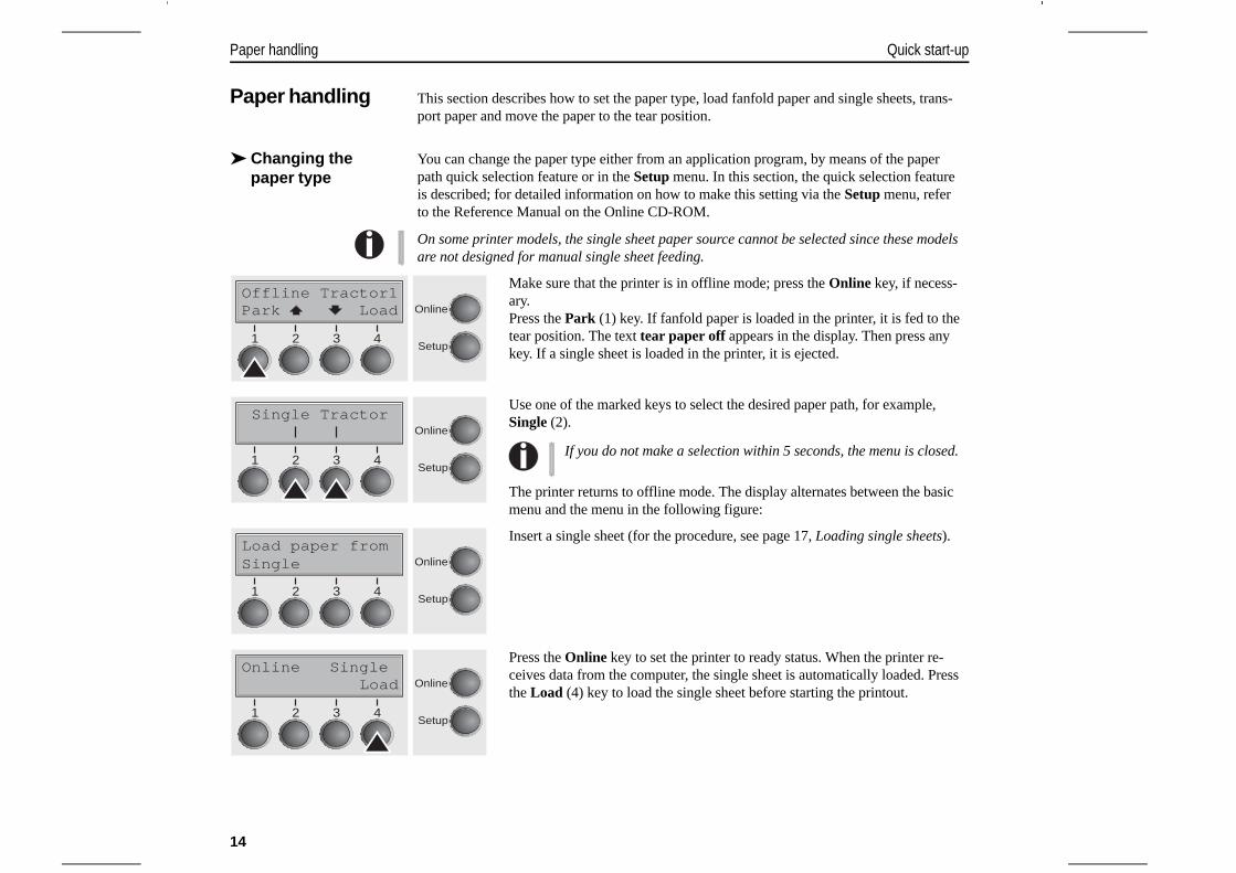
Make sure that the printer is in offline mode; press the Online key, if necess-ary.Press the Park (1) key. If fanfold paper is loaded in the printer, it is fed to thetear position. The text tear paper off appears in the display. Then press anykey. If a single sheet is loaded in the printer, it is ejected.
Use one of the marked keys to select the desired paper path, for example,Single (2).
The printer returns to offline mode. The display alternates between the basicmenu and the menu in the following figure:
Insert a single sheet (for the procedure, see page 17, Loading single sheets).
Press the Online key to set the printer to ready status. When the printer re-ceives data from the computer, the single sheet is automatically loaded. Pressthe Load (4) key to load the single sheet before starting the printout.
Offline Tractor1Park Load Online
Setup21 3 4
Single TractorOnline
Setup21 3 4
If you do not make a selection within 5 seconds, the menu is closed.
Load paper fromSingle Online
Setup21 3 4
Online SingleLoad Online
Setup21 3 4
Paper handling Quick start-up
14
➤ Loading paper Your printer can process both fanfold paper and single sheets. For information on thesupported paper sizes, please refer to page 25 (Paper specifications).
You should only use those paper types which are approved for this printer. For more infor-mation, please refer to the Reference Manual on the Online CD-ROM.
Fanfold paper
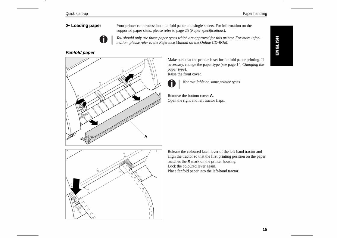
Make sure that the printer is set for fanfold paper printing. Ifnecessary, change the paper type (see page 14, Changing thepaper type).Raise the front cover.
Remove the bottom cover A.Open the right and left tractor flaps.
Release the coloured latch lever of the left-hand tractor andalign the tractor so that the first printing position on the papermatches the X mark on the printer housing.Lock the coloured lever again.Place fanfold paper into the left-hand tractor.
A
Not available on some printer types.
EN
GLIS
H
Quick start-up Paper handling
15

Open the coloured latch lever of the right-hand tractor andalign it to the paper width.Insert the fanfold paper into the right-hand tractor.Make sure that it is inserted by the same length as on the left-hand tractor in order to avoid any paper jam.Close the tractor flap and lock the tractor by turning the trac-tor lever to the rear.
Be sure to align the paper stack in parallel with the printerand that the paper flow is unobstructed.
Re-install the bottom cover.Lower the front cover.Switch the printer on. The active paper source (Traktor1) appears in the dis-play. The paper is automatically loaded when the printer is in online modeand receives data from the computer.Press the Load (4) key to load paper before starting the printout.
Do not tighten the paper excessively to avoid tear-ing the perforation holes; do not allow excessiveslack or the paper will not remain flat enough to en-sure accurate feeding.
90
Online Tractor1Load Online
Setup21 3 4
Paper handling Quick start-up
16
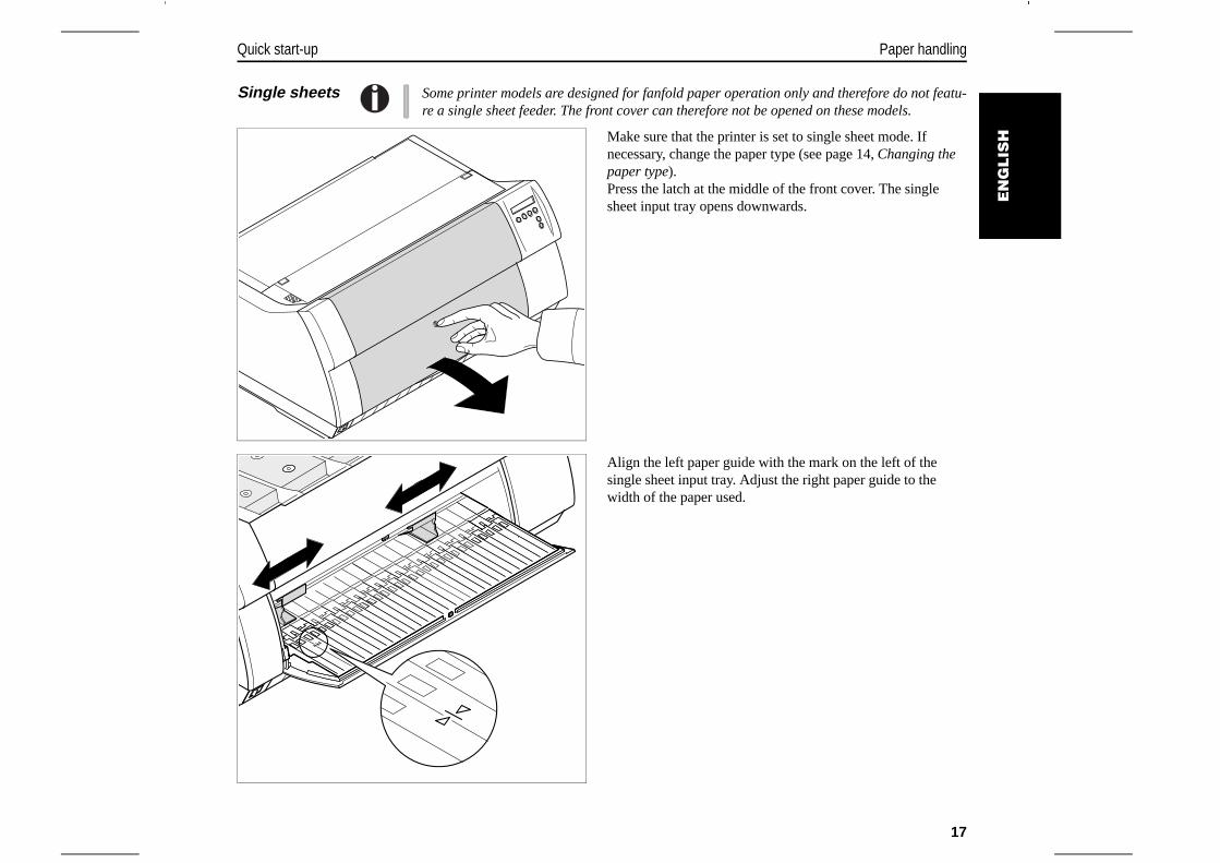
Single sheets Some printer models are designed for fanfold paper operation only and therefore do not featu-re a single sheet feeder. The front cover can therefore not be opened on these models.
Make sure that the printer is set to single sheet mode. Ifnecessary, change the paper type (see page 14, Changing thepaper type).Press the latch at the middle of the front cover. The singlesheet input tray opens downwards.
Align the left paper guide with the mark on the left of thesingle sheet input tray. Adjust the right paper guide to thewidth of the paper used.
EN
GLIS
H
Quick start-up Paper handling
17
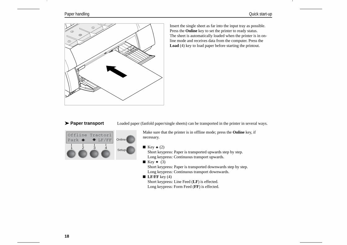
Insert the single sheet as far into the input tray as possible.Press the Online key to set the printer to ready status.The sheet is automatically loaded when the printer is in on-line mode and receives data from the computer. Press theLoad (4) key to load paper before starting the printout.
➤ Paper transport Loaded paper (fanfold paper/single sheets) can be transported in the printer in several ways.
Make sure that the printer is in offline mode; press the Online key, ifnecessary.
Key (2)Short keypress: Paper is transported upwards step by step.Long keypress: Continuous transport upwards.
Key (3)Short keypress: Paper is transported downwards step by step.Long keypress: Continuous transport downwards.
LF/FF key (4)Short keypress: Line Feed (LF) is effected.Long keypress: Form Feed (FF) is effected.
Offline Tractor1Online
Setup
Park LF/FF
21 3 4
Paper handling Quick start-up
18
➤ Moving the paper to the tear position
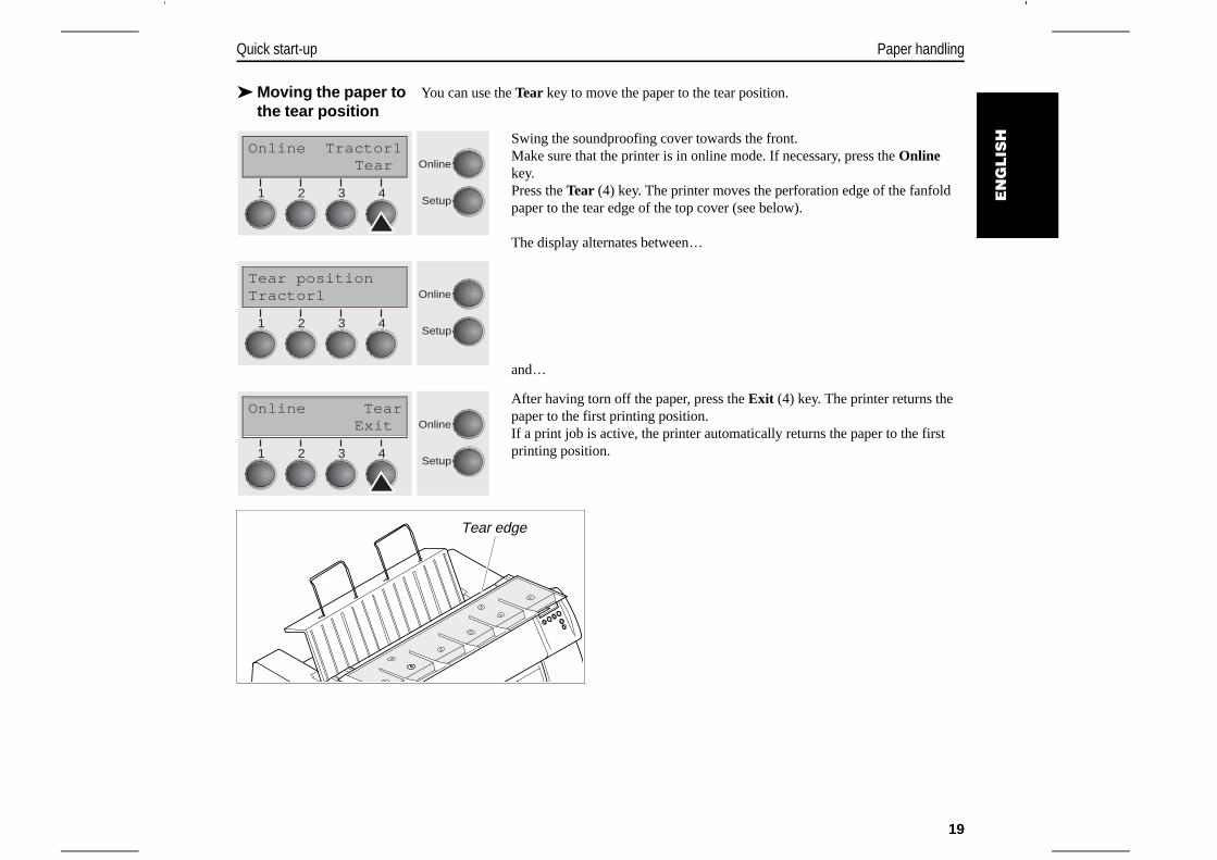
You can use the Tear key to move the paper to the tear position.
Swing the soundproofing cover towards the front.Make sure that the printer is in online mode. If necessary, press the Onlinekey.Press the Tear (4) key. The printer moves the perforation edge of the fanfoldpaper to the tear edge of the top cover (see below).
The display alternates between…
and…
After having torn off the paper, press the Exit (4) key. The printer returns thepaper to the first printing position. If a print job is active, the printer automatically returns the paper to the firstprinting position.
Online Tractor1Tear Online
Setup21 3 4
Tear positionTractor1 Online
Setup21 3 4
Online TearExit Online
Setup21 3 4
Tear edge
EN
GLIS
H
Quick start-up Paper handling
19
Settings This section describes how to set the tear position, the first printing line, the print head gap aswell as the font selection and the character density.
➤ Setting the tear position
If the tear position of the paper is not aligned with the tear edge of the top cover of the printer,you can adjust it.
Press the Setup key. The printer changes to setup mode. Press the Adjust (2) key.
Press the Tear (4) key. The printer performs a form feed.
Press the < (2) or > (3) key to move the perforation to the desired position.Confirm the input by pressing the Set (1) key.Confirm the input again by pressing the Setup key. The printer is reset to theinitial status.
The correction made – a maximum of approx. 2.5 cm (1") in each direction – will be retainedafter switching the printer off.
Adjust PaperwayMenu Char Online
Setup21 3 4
TOFHead Tear Online
Setup21 3 4
TearAdj= 00/72"*Set < > Exit Online
Setup21 3 4
Settings Quick start-up
20
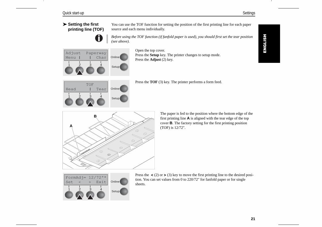
➤ Setting the first printing line (TOF)
You can use the TOF function for setting the position of the first printing line for each papersource and each menu individually.
Before using the TOF function (if fanfold paper is used), you should first set the tear position(see above).
Open the top cover.Press the Setup key. The printer changes to setup mode. Press the Adjust (2) key.
Press the TOF (3) key. The printer performs a form feed.
The paper is fed to the position where the bottom edge of thefirst printing line A is aligned with the tear edge of the topcover B. The factory setting for the first printing position(TOF) is 12/72".
Press the < (2) or > (3) key to move the first printing line to the desired posi-tion. You can set values from 0 to 220/72" for fanfold paper or for singlesheets.
Adjust PaperwayMenu Char Online
Setup21 3 4
TOFHead Tear Online
Setup21 3 4
Computerdrucker
Computerdrucker
A
B
FormAdj= 12/72"*Set < > Exit Online
Setup21 3 4
EN
GLIS
H
Quick start-up Settings
21
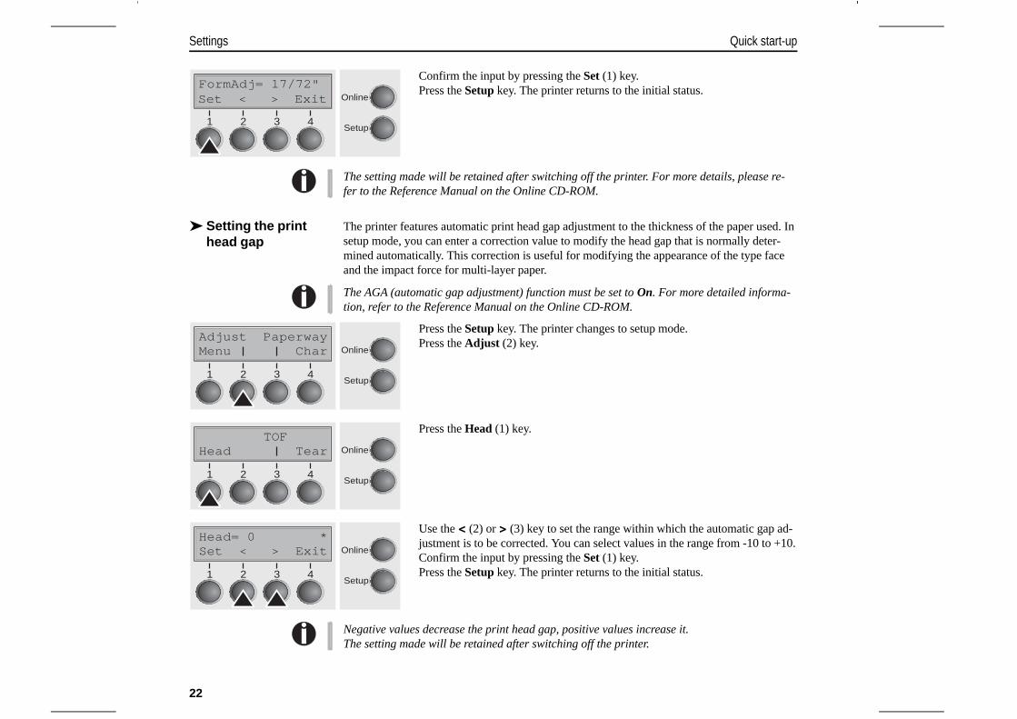
Confirm the input by pressing the Set (1) key.Press the Setup key. The printer returns to the initial status.
The setting made will be retained after switching off the printer. For more details, please re-fer to the Reference Manual on the Online CD-ROM.
➤ Setting the printhead gap
The printer features automatic print head gap adjustment to the thickness of the paper used. Insetup mode, you can enter a correction value to modify the head gap that is normally deter-mined automatically. This correction is useful for modifying the appearance of the type faceand the impact force for multi-layer paper.
The AGA (automatic gap adjustment) function must be set to On. For more detailed informa-tion, refer to the Reference Manual on the Online CD-ROM.
Press the Setup key. The printer changes to setup mode. Press the Adjust (2) key.
Press the Head (1) key.
Use the < (2) or > (3) key to set the range within which the automatic gap ad-justment is to be corrected. You can select values in the range from -10 to +10.Confirm the input by pressing the Set (1) key.Press the Setup key. The printer returns to the initial status.
Negative values decrease the print head gap, positive values increase it.The setting made will be retained after switching off the printer.
FormAdj= 17/72"Set < > Exit Online
Setup21 3 4
Adjust PaperwayMenu Char Online
Setup21 3 4
TOFHead Tear Online
Setup21 3 4
Head= 0 *Set < > Exit Online
Setup21 3 4
Settings Quick start-up
22
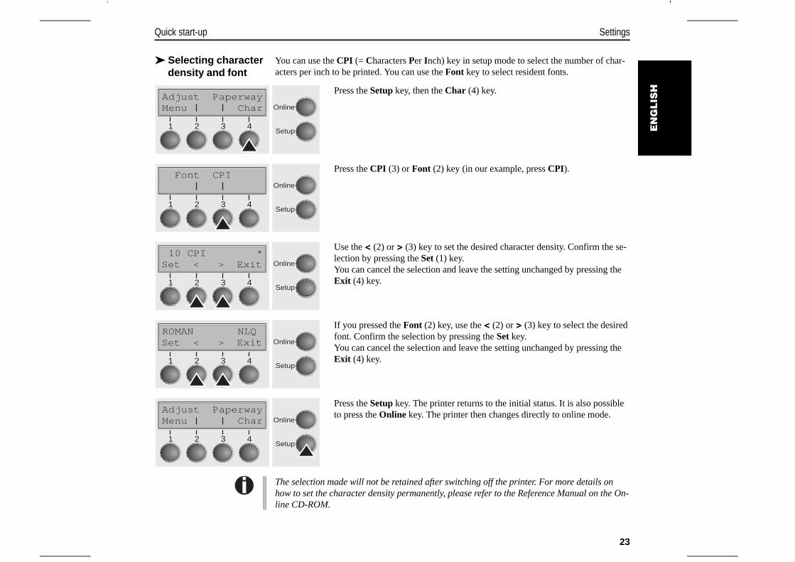
➤ Selecting characterdensity and font
You can use the CPI (= Characters Per Inch) key in setup mode to select the number of char-acters per inch to be printed. You can use the Font key to select resident fonts.
Press the Setup key, then the Char (4) key.
Press the CPI (3) or Font (2) key (in our example, press CPI).
Use the < (2) or > (3) key to set the desired character density. Confirm the se-lection by pressing the Set (1) key.You can cancel the selection and leave the setting unchanged by pressing theExit (4) key.
If you pressed the Font (2) key, use the < (2) or > (3) key to select the desiredfont. Confirm the selection by pressing the Set key.You can cancel the selection and leave the setting unchanged by pressing theExit (4) key.
Press the Setup key. The printer returns to the initial status. It is also possibleto press the Online key. The printer then changes directly to online mode.
The selection made will not be retained after switching off the printer. For more details onhow to set the character density permanently, please refer to the Reference Manual on the On-line CD-ROM.
Adjust PaperwayMenu Char Online
Setup21 3 4
Font CPIOnline
Setup21 3 4
10 CPI *Set < > Exit Online
Setup21 3 4
ROMAN NLQSet < > Exit Online
Setup21 3 4
Adjust PaperwayMenu Char Online
Setup21 3 4
EN
GLIS
H
Quick start-up Settings
23
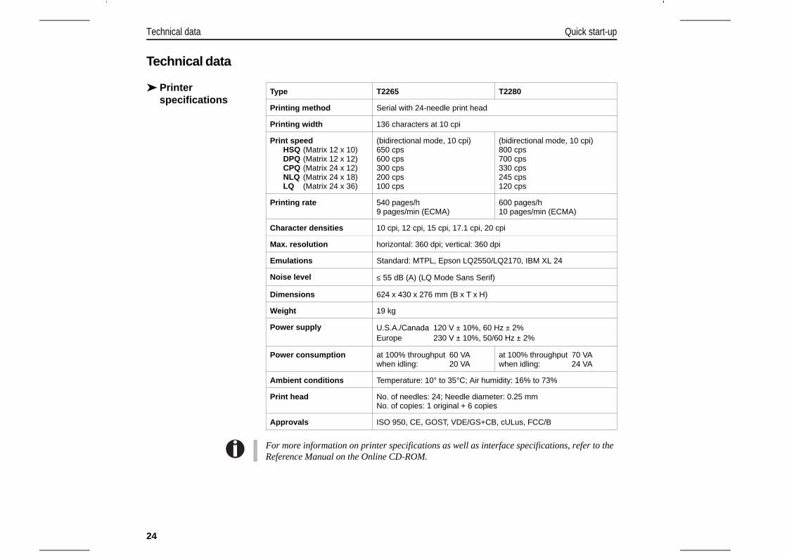
Technical data
➤ Printerspecifications
For more information on printer specifications as well as interface specifications, refer to theReference Manual on the Online CD-ROM.
Type T2265 T2280
Printing method Serial with 24-needle print head
Printing width 136 characters at 10 cpi
Print speedHSQ (Matrix 12 x 10)DPQ (Matrix 12 x 12)CPQ (Matrix 24 x 12)NLQ (Matrix 24 x 18)LQ (Matrix 24 x 36)
(bidirectional mode, 10 cpi)650 cps600 cps300 cps200 cps 100 cps
(bidirectional mode, 10 cpi)800 cps700 cps330 cps245 cps120 cps
Printing rate 540 pages/h 9 pages/min (ECMA)
600 pages/h 10 pages/min (ECMA)
Character densities 10 cpi, 12 cpi, 15 cpi, 17.1 cpi, 20 cpi
Max. resolution horizontal: 360 dpi; vertical: 360 dpi
Emulations Standard: MTPL, Epson LQ2550/LQ2170, IBM XL 24
Noise level ≤ 55 dB (A) (LQ Mode Sans Serif)
Dimensions 624 x 430 x 276 mm (B x T x H)
Weight 19 kg
Power supply U.S.A./Canada 120 V ± 10%, 60 Hz ± 2%Europe 230 V ± 10%, 50/60 Hz ± 2%
Power consumption at 100% throughput 60 VAwhen idling: 20 VA
at 100% throughput 70 VAwhen idling: 24 VA
Ambient conditions Temperature: 10° to 35°C; Air humidity: 16% to 73%
Print head No. of needles: 24; Needle diameter: 0.25 mmNo. of copies: 1 original + 6 copies
Approvals ISO 950, CE, GOST, VDE/GS+CB, cULus, FCC/B
Technical data Quick start-up
24

➤ Paperspecifications
For more information on general paper specifications as well as paper specifications for theoptional tractor units and the automatic sheet feeder, refer to the Reference Manual on theOnline CD-ROM.
Fanfold paper Tractor1Continuous single formsSingle set of forms (requires individual testing)
Paper weightNo. of copiesForm thickness (max.)
60–120 g/m2
1 + 60.60 mm
Single sheet feederSingle sheetsSingle set of forms (requires individual testing)
Paper weightNo. of copiesForm thickness (max.)
80–120 g/m2
1 + 50.60 mm
Sets of forms Sets of forms can only be processed if the top edge is bound.ASF-F: Multi-part forms must be loaded with the bound topedge down. They must be tested individually for theirsuitability.
EN
GLIS
H
Quick start-up Technical data
25
Accessories
For additional accessories, please refer to the Reference Manual on the Online-CD-ROM.
Ribbon cassettes Order no.
Black ribbon cassette 060097
Ribbon cassette 1 x red, 3 x black 060099
Ribbon cassette with yellow, magenta, cyan, black 060098
Ribbon cassette with red, green, blue, black 060100
Accessories Quick start-up
26

“All rights reserved. Translations, reprinting or copying by any means of this manual complete or in part or in any different form requires our explicit approval.We reserve the right to make changes to this manual without notice. All care has been taken to ensure accuracy of information contained in this manual.However, we cannot accept responsibility for any errors or damages resulting from errors or inaccuracies of information herein.”
TRADEMARK ACKNOWLEDGEMENTS“CENTRONICS” is a trademark of Centronics DataComputer Corporation.“EPSON” and “EPSON ESC/P” are registeredtrademarks and “EPSON/P2” is a trademark ofSEIKO EPSON Corporation.“IBM” is a trademark of International BusinessMachines Corporation.“MS-DOS” is a trademark of Microsoft Corporation.“Windows”, “Windows 95”, “Windows 98“, “WindowsME“, “Windows 2000“ and “Windows NT” aretrademarks of Microsoft Corporation.
© September 2001 Tally Computerdrucker GmbH 063 050a
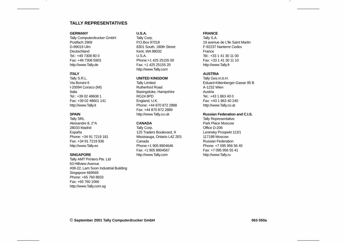
TALLY REPRESENTATIVES
FRANCETally S.A.19 avenue de L’lle Saint MartinF-92237 Nanterre CedexFranceTél.: +33 1 41 30 11 00Fax: +33 1 41 30 11 10http://www.Tally.fr
AUSTRIATally Ges.m.b.H.Eduard-Kittenberger-Gasse 95 BA-1232 WienAustriaTel.: +43 1 863 40 0Fax: +43 1 863 40 240http://www.Tally.co.at
Russian Federation and C.I.S.Tally RepresentativePark Place MoscowOffice D-206Leninsky Prospekt 113/1117198 MoscowRussian FederationPhone: +7 095 956 56 40Fax: +7 095 956 55 41http://www.Tally.ru
GERMANYTally Computerdrucker GmbHPostfach 2969D-89019 UlmDeutschlandTel.: +49 7308 80 0Fax: +49 7308 5903http://www.Tally.de
ITALYTally S.R.L.Via Borsini 6I-20094 Corsico (MI)ItaliaTel.: +39 02 48608 1Fax: +39 02 48601 141http://www.Tally.it
SPAINTally SRLAleixandre 8, 2°A28033 MadridEspañaPhone: +34 91 7219 181Fax: +34 91 7219 936http://www.Tally.es
SINGAPORETally AMT Printers Pte. Ltd63 Hillview Avenue#08-22, Lam Soon Industrial BuildingSingapore 669569Phone: +65 760 8833Fax: +65 760 1066http://www.Tally.com.sg
U.S.A.Tally Corp.P.O.Box 970188301 South, 180th StreetKent, WA 98032U.S.A.Phone:+1 425 25155 00Fax: +1 425 25155 20http://www.Tally.com
UNITED KINGDOMTally LimitedRutherford RoadBasingstoke, HampshireRG24 8PDEngland, U.K.Phone: +44 870 872 2888Fax: +44 870 872 2889http://www.Tally.co.uk
CANADATally Corp.125 Traders Boulevard, 9Missisauga, Ontario L4Z 2E5CanadaPhone:+1 905 8904646Fax: +1 905 8904567http://www.Tally.com

![Hypnosis and posthypnotic suggestions[3] · HYPNOSIS AND POSTHYPNOTIC SUGGESTIONS Lars-Erik Unestål. Ph.D. Uppsala University CHAPTER III. POSTHYPNOTIC SUGGESTIONS Posthypnotic Suggestions](https://img.pdfslide.net/doc/110x75/5e807de82eb6152f8c71e232/hypnosis-and-posthypnotic-suggestions3-hypnosis-and-posthypnotic-suggestions-lars-erik.jpg)