Embed Size (px)
Citation preview

9.800-081.0
OPERATOR’S MANUAL
®
To locate your local Kärcher Shark Commercial Pressure Washer Dealer nearest you,visit www.karchercommercial.com or www.karchershark.com
MODEL # ORDER #
HDS 5.0/30 Ed / HP-5030D 1.575-650.0

CONTENTS
2
Model Number ______________________________
Serial Number ______________________________
Date of Purchase ____________________________The model and serial numbers will be found on a decal attached to the machine. You should record both serial number and date of purchase and keep in a safe place for future reference.
Karcher • HDS 650 • 9.800-081.0 • Rev. 5/10a
Introduction 3
Important Safety Information 3-5
Installation 5,7
Component Identification 6
Installation 7
Operating Instructions 8
Detergents & General Operating Techniques 9
Shutting Down & Cleanup 10
Troubleshooting 11-12
Preventative Maintenance 12-13
Maintenance and Service 13-15
Machine Assembly Exploded View 16
Machine Assembly Exploded View Parts List 17
Burner Assembly, Exploded View 18
Burner Assembly Exploded View Parts Lists 19
Warranty

Karcher • HDS 650 • 9.800-081.0 • Rev. 5/10a3
PR
ES
SU
RE
WA
SH
ER
OP
ER
AT
OR
’S M
AN
UA
L
INTRODUCTION & IMPORTANT SAFETY INFORMATION
Thank you for purchasing this Pressure Washer.
We reserve the right to make changes at any time without incurring any obligation.
Owner/User Responsibility:The owner and/or user must have an understanding of the manufacturer’s operating instructions and warnings before using this pressure washer. Warning information should be emphasized and understood. If the operator is not fluent in English, the manufacturer’s instruc-tions and warnings shall be read to and discussed with the operator in the operator’s native language by the purchaser/owner, making sure that the operator comprehends its contents.
Owner and/or user must study and maintain for future reference the manufacturers’ instructions.
The operator must know how to stop the machine quickly and understand the operation of all controls. Never permit anyone to operate the engine without proper instructions.
This manual should be considered a permanent part of the machine and should remain with it if machine is resold.
When ordering parts, please specify model and serial number. Use only identical replacement parts.
This machine is to be used only by trained operators.
IMPORTANT SAFETY INFORMATION
READ OPERATOR’S MANUAL THOROUGHLY
PRIOR TO USE.
WARNING: To reduce the risk of injury, read operating instruc-tions carefully before using.
1. Read the owner's manual thoroughly. Failure to follow instructions could cause mal-function of the machine and result in death, serious bodily injury and/or property damage.
2. Know how to stop the ma-chine and bleed pressure quickly. Be thoroughly fa-miliar with the controls.
3. Stay alert — watch what you are doing.
4. All installations must comply with local codes. Contact your electrician, plumber, utility company or the selling distributor for specific details. If your machine is rated 250 volts or less, single phase will be provided with a ground fault circuit interrupter (GFCI). If rated more than 250 volts, or more than single phase this product should only be con-nected to a power supply receptacle protected by a GFCI.
DANGER: Improper connection of the equip-ment-grounding conductor can result in a risk of electrocution. Check with a qualified electrician or service personnel if you are in doubt as to whether the outlet is properly grounded. Do not modify the plug provided with the product - if it will not fit the outlet, have a proper outlet installed by a qualified electrician. Do not use any type of adaptor with this product
WARNING
KEEP WATER SPRAY AWAY FROM
ELECTRICAL WIRING.
WARNING: Keep wand, hose, and water spray away from electric wiring or fatal electric shock may result.
5. To protect the operator from electrical shock, the machine must be electrically grounded. It is the responsibility of the owner to connect this machine
to a UL grounded receptacle of proper voltage and amperage ratings. Do not spray water on or near electrical components. Do not touch machine with wet hands or while standing in water. Always disconnect power before servicing.
RISK OF EXPLOSION: OPERATE ONLY WHERE OPEN FLAME OR TORCH
IS PERMITTED
WARNING WARNING: Flammable liquids can create fumes which can ig-nite, causing property damage or severe injury.
WARNING: Risk of explosion — Operate only where open flame or torch is permitted.
6. In oil burning models, use only kerosene, No. 1 home heating fuel, or diesel. If diesel is used, add a soot remover to every tankful.
RISK OF FIRE. DO NOT ADD FUEL WHEN OPERATING
MACHINE.
WARNING WARNING: Risk of fire — Do not add fuel when the product is operating or still hot.
WARNING: Do not use gasoline crankcase draining or oil con-taining gasoline, solvents or alcohol. Doing so will result in fire and/or explosion.
7. Oil burning appliances shall be installed only in locations where combustible dusts and flammable gases or vapors are not present. Do not store or use gasoline near this machine.
8. Do not allow acids, caustic or abrasive fluids to pass through the pump.
9. Never run pump dry or leave spray gun closed longer than 1-2 minutes.
10. Keep operating area clear of all persons.

Karcher • HDS 650 • 9.800-081.0 • Rev. 5/10a
OP
ER
AT
OR
’S M
AN
UA
L
PR
ES
SU
RE
WA
SH
ER
4
RISK OF INJECTION OR SEVERE INJURY TO PERSONS. KEEP CLEAR OF NOZZLE.
WARNING WARNING: High pressure de-veloped by these machines will cause personal injury or equip-ment damage. Keep clear of nozzle. Use caution when oper-ating. Do not direct discharge stream at people, or severe injury or death will result.
WARNING
PROTECT FROM FREEZING
WARNING: Protect machine from freezing.
15. To keep machine in best operating conditions, it is important you protect machine from freezing. Failure to protect machine f rom f reezing could cause malfunction of the machine and result in death,
serious bodily injury, and/or property damage. Fol-low storage instructions specified in this manual.
16. Inlet water must be clean fresh water and no hotter then 90°F.
WARNING
RISK OF ASPHYXIATION: USE THIS PRODUCT ONLY
IN A WELL VENTILATED AREA.
WARNING: Risk of asphyxiation. Use this product only in a well ventilated area.
17. Avoid installing machines in small areas or near ex-haust fans. Adequate ox-ygen is needed for com-bustion or dangerous car-bon monoxide will result.
18. Manufacturer will not be liable for any changes made to our standard machines or any compo-nents not purchased from us.
19. The best insurance against an accident is precau-tion and knowledge of the machine.
WARNING
RISK OF INJURY FROM FALLS WHEN
USING LADDER.
WARNING: Be extremely careful when using a ladder, scaffold-ing or any other relatively un-stable location. The cleaning area should have adequate slopes and drainage to reduce the possibility of a fall due to slippery surfaces.
20. Do not overreach or stand on unstable support. Keep good footing and balance at all times.
21. Do not operate this machine when fatigued or under the influence of alcohol, prescription medi-cations, or drugs.
IMPORTANT SAFETY INFORMATION
WARNING
USE PROTECTIVE EYE WEAR
AND CLOTHING WHEN OPERATING THIS EQUIPMENT.
WARNING: High pressure spray can cause paint chips or other particles to become airborne and fly at high speeds. To avoid personal injury, eye, hand and foot safety devices must be worn.
11. Eye, hand, and foot pro-tection must be worn when u s i n g t h i s e q u i p m e n t .
WARNING
EAR PROTECTION MUST BE WORN
WARNING: This machine exceeds 85 db appropriate ear protection must be worn.
WARNING
HOT DISCHARGE FLUID: DO NOT TOUCH OR DIRECT DISCHARGE
STREAM AT PERSONS.
WARNING: Hot discharge fluid. Do not touch or direct discharge stream at persons.
WARNING: This machine pro-duces hot water and must have insulated components attached to protect the operator.
WARNING
RISK OF INJURY: HOT SURFACES
CAN CAUSE BURNS
WARNING: Risk of injury. Hot surfaces can cause burns. Use only designated gripping areas of spray gun and wand. Do not place hands or feet on non-insu-lated areas of the pressure washer.
12. To reduce the risk of injury, close supervision is
necessary when a machine is used near children. Do not allow children to operate the pressure washer. This machine must be attended during operation.
TRIGGER GUN KICKS BACK - HOLD WITH
BOTH HANDS
WARNING WARNING: Grip cleaning wand securely with both hands before starting. Failure to do this could result in injury from a whipping wand.
13. Never make adjustments on ma-chine while in operation.
14. Be certain all quick cou-pler fittings are secured be-fore using pressure washer.

Karcher • HDS 650 • 9.800-081.0 • Rev. 5/10a5
PR
ES
SU
RE
WA
SH
ER
OP
ER
AT
OR
’S M
AN
UA
L
IMPORTANT SAFETY INFORMATION
Follow the maintenance instructions specified in the manual.

Karcher • HDS 650 • 9.800-081.0 • Rev. 5/10a
OP
ER
AT
OR
’S M
AN
UA
L
PR
ES
SU
RE
WA
SH
ER
6
COMPONENT IDENTIFICATION
Pressure Washer3,000 PSI Maximum
(not included)
Fresh Water Faucet
Garden Hose (not included)
Insulated Wand (not included)
Pressure Washer to Inlet Hose
Inlet Connection
Outlet Connection
High Pressure Outlet Hose(not included)
Power Cord
Diesel Fuel Tank
InsulatedSpray Gun
(not included)
Pressure Washer Coupler
CAUTION HOT WATER: Must use insulated spray gun and wand.
GFCI

Karcher • HDS 650 • 9.800-081.0 • Rev. 5/10a7
PR
ES
SU
RE
WA
SH
ER
OP
ER
AT
OR
’S M
AN
UA
L
Place machine in a convenient location providing ample support, drainage and room for maintenance.
Remove bolts from pallet to foot bracket. Install rubber feet provided as shown on page 16.
Location:The location should protect the machine from damag- ing environmental conditions, such as; wind, rain, and freezing.
1. This machine should be run on a level surface where it is not readily influenced by outside sources such as strong winds, freezing temperatures, rain, etc. It should be located to allow accessibility for refilling of fuel, adjustments and maintenance. Nor-mal precautions should be taken by the operator of the machine to prevent moisture from reaching the electrical controls.
2. It is recommended that a partition be made be-tween the wash area and the machine to prevent water spray from coming in contact with the ma-chine. Excess moisture reaching any electric com-ponents or electrical controls will reduce machine life and may cause electrical shorts.
3. During installation of the machine, beware of poorly ventilated locations or areas where exhaust fans may cause an insufficient supply of oxygen. Sufficient combustion can only be obtained when there is a sufficient supply of oxygen available for the amount of fuel being burned. If it is necessary to install a machine in a poorly ventilated area, outside fresh air may have to be piped to the burner and a fan installed to bring air into the machine.
Electrical:This machine, when installed, must be electrically grounded in accordance to local codes. Check for proper power supply using a volt meter.
Placement:Do not locate near any combustible material. Keep all flammable material at least 20 feet away.
Allow enough space for servicing the machine.
Local code will require certain distances from floor and walls. (Two feet away from walls should be ad-equate.)
Water Source:The water source for the pressure washer should be supplied by a minimum 5/8" I.D. garden hose with a city water pressure of not less than 30 PSI. If the water supply is inadequate, or if the garden hose is kinked, the attached pressure washer will run very rough and the burner will not fire.
Connection:See Component Identification.
Venting:Adding exhaust vent pipe to your oil fired burner is not recommended because restricted air flow causes carbon build-up, which affects the operation, and in-creases maintenance on the coil. If a stack must be used, refrain from using 90° bends. If the pipe can not go straight up then use only 45° bends and go to the next size pipe. The overall pipe length must not exceed 6 feet in length. The burner air adjustment must be performed after vent pipe is installed. Use a smoke tester for proper air setting.
INSTALLATION
Karcher • HDS 650 • 9.800-081.0 • Rev. 5/10a
OP
ER
AT
OR
’S M
AN
UA
L
PR
ES
SU
RE
WA
SH
ER
8
OPERATING INSTRUCTIONS
STEP 1: Check fuel tank and pump oil levels on both machines and connect garden hose to pressure washer. CAUTION: Only use fresh water to this machine.
STEP 2: Attach high pressure hose between pressure washer and ma-chine. Turn garden hose water on. Additional adapters and couplers may be needed to connect your brand of pressure washer to the machine.
STEP 4: Connect the power cord into the proper electrical outlet, then push in the GFCI reset button. Start up attached pressure washer according to the manufacturers in-structions. When a steady stream of water flows from the spray gun and wand the machine is ready for cold water cleaning.
STEP 4: For hot water washing, turn the machine burner switch to the ON position. Adjust thermostat to desired temperature setting. (The burner will light automatically.)

Karcher • HDS 650 • 9.800-081.0 • Rev. 5/10a9
PR
ES
SU
RE
WA
SH
ER
OP
ER
AT
OR
’S M
AN
UA
L
WARNING: Some detergents may be harmful if inhaled or ingested, causing severe nau-sea, fainting or poisoning. The harmful elements may cause property damage or severe injury.
STEP 1: Use detergent designed specifically for pressure washers. Household detergents could dam-age the pump. Prepare detergent solution as required by the manu-facturer. Fill a container with pres-sure washer detergent. Place the filter end of detergent suction tube into the detergent container.
STEP 2: With the motor running, pull trigger to operate machine. Liquid detergent is drawn into the machine and mixed with water. Apply detergent to work area. Do not allow detergent to dry on surface.
IMPORTANT: You must flush the detergent injection system after each use by plac-ing the suction tube into a bucket of clean water, then run the pressure washer in low pressure for 1-2 minutes.
CLEANING TIPSPre-rinse cleaning surface with fresh water. Place de-tergent suction tube directly into cleaning solution and apply to surface at low pressure (for best results, limit your work area to sections approximately 6 feet square and always apply detergent from bottom to top). Allow detergent to remain on surface 1-3 minutes. Do not allow detergent to dry on surface. If surface appears to be drying, simply wet down surface with fresh water. If needed, use brush to remove stubborn dirt. Rinse at high pressure from top to bottom in an even sweeping motion keeping the spray nozzle approximately 1 foot from cleaning surface. Use overlapping strokes as you clean and rinse any surface. For best surface cleaning action spray at a slight angle.
Recommendations: • Before cleaning any surface, an inconspicuous
area should be cleaned to test spray pattern and distance for maximum cleaning results.
• If painted surfaces are peeling or chipping, use extreme caution as pressure washer may remove the loose paint from the surface.
• Keep the spray nozzle a safe distance from the surface you plan to clean. High pressure wash a small area, then check the surface for dam-age. If no damage is found, continue to pressure washing.
CAUTION - Never use: • Bleach, chlorine and other corrosive chemicals • Liquids containing solvents (i.e., paint thinner,
gasoline, oils) • Tri-sodium phosphate products • Ammonia products • Acid-based productsThese chemicals will harm the machine and will dam-age the surface being cleaned.
RINSINGIt will take a few seconds for the detergent to clear. Apply safety latch to spray gun. Remove black soap nozzle from the quick coupler. Select and install the desired high pressure nozzle. NOTE: You can also stop detergent from flowing by simply removing detergent siphon tube from bottle.
WARNING
DETERGENTS AND GENERAL OPERATING TECHNIQUES
Karcher • HDS 650 • 9.800-081.0 • Rev. 5/10a
OP
ER
AT
OR
’S M
AN
UA
L
PR
ES
SU
RE
WA
SH
ER
10
SHUTTING DOWN AND CLEAN-UP
CAUTION: Always store your pressure washer in a location where the temperature will not fall below 32°F (0°C). The pump in this machine is susceptible to permanent damage if frozen. FREEZE DAMAGE IS NOT COVERED BY WARRANTY.
1. Stop the pressure washer, squeeze spray gun trigger to release pressure.
2. Detach water supply hose and high pressure hose.
3. Turn on the machine for a few seconds, until re-maining water exits. Turn engine off immediately.
4. Drain the gas and oil from the engine.
5. Do not allow high pressure hose to become kinked.
6. Store the machine and accessories in a room which does not reach freezing temperatures.
CAUTION: Failure to follow the above directions will result in damage to your pressure washer.When the pressure washer is not being operated or is being stored for more than one month, follow these instructions:
1. Replenish engine oil to upper level.
2. Drain gasoline from fuel tank, fuel line, fuel valve and carburetor.
3. Pour about one teaspoon of engine oil through the spark plug hole, pull the starter grip several times and replace the plug. Then pull the starter grip slowly until you feel increased pressure which indicates the piston is on its compression stroke and leave it in that position. This closes both the intake and exhaust valves to prevent rusting of cylinder.
4. Cover the pressure washer and store in a clean, dry place that is well ventilated away from open flame or sparks. NOTE: The use of a fuel additive, such as STA-BIL®, or an equivalent, will minimize the formulation of fuel deposits during shortage. Such additives may be added to the gasoline in the fuel tank of the engine, or to the gasoline in a storage container.
After Extended StorageCAUTION: Prior to restarting, thaw out any possible ice from pressure washer hoses, spray gun or wand.
Engine MaintenanceDuring the winter months, rare atmospheric conditions may develop which will cause an icing condition in the carburetor. If this develops, the engine may run rough, lose power and may stall. This temporary condition can be overcome by deflecting some of the hot air from the engine over the carburetor area. NOTE: Refer to the engine manufacturer’s manual for service and mainte-nance of the engine.
STORAGE
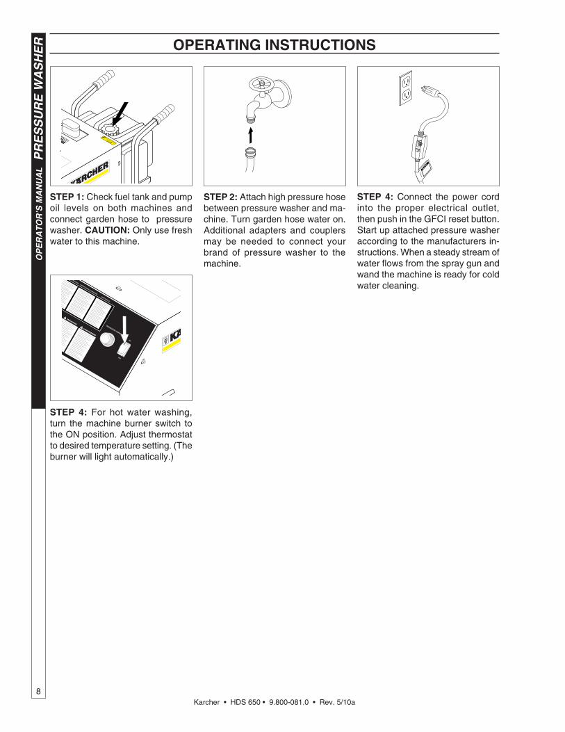
STEP 1: If using an op-tional detergent injector, place the detergent line in a bucket of water allowing detergent to be flushed from system.
STEP 2: Turn burner switch off and continue spraying water, allowing the water to cool. After water has cooled to less than 100°F, turn the at-tached pressure washer off.
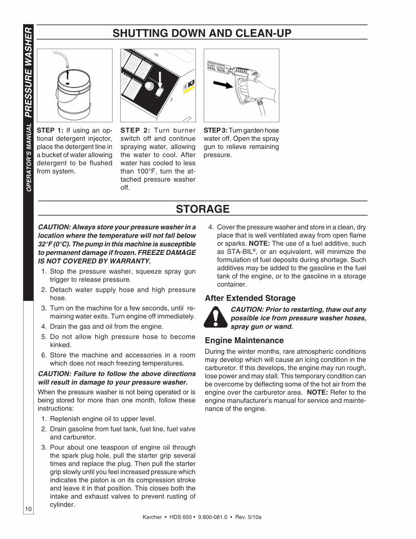
STEP 3: Turn garden hose water off. Open the spray gun to relieve remaining pressure.
Karcher • HDS 650 • 9.800-081.0 • Rev. 5/10a11
PR
ES
SU
RE
WA
SH
ER
Tro
ub
lesho
otin
g G
uid
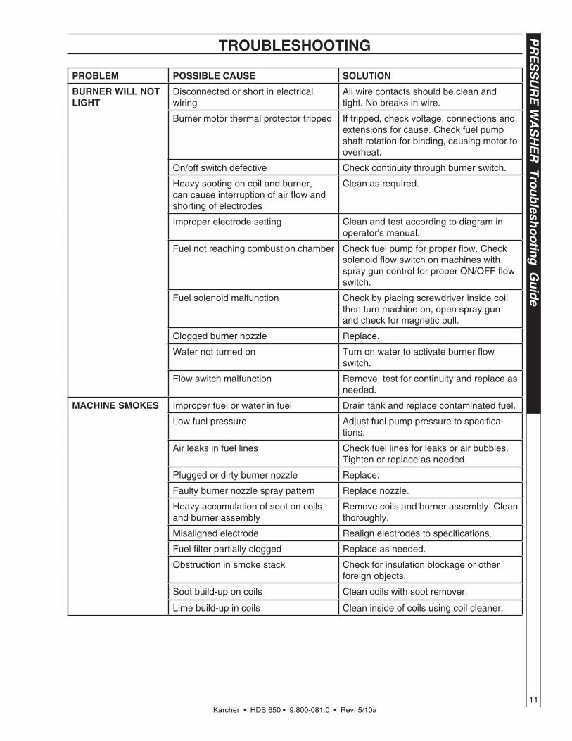
eTROUBLESHOOTING
PROBLEM POSSIBLE CAUSE SOLUTION
BURNER WILL NOT LIGHT
Disconnected or short in electrical wiring
All wire contacts should be clean and tight. No breaks in wire.
Burner motor thermal protector tripped If tripped, check voltage, connections and extensions for cause. Check fuel pump shaft rotation for binding, causing motor to overheat.
On/off switch defective Check continuity through burner switch.
Heavy sooting on coil and burner, can cause interruption of air flow and shorting of electrodes
Clean as required.
Improper electrode setting Clean and test according to diagram in operator's manual.
Fuel not reaching combustion chamber Check fuel pump for proper flow. Check solenoid flow switch on machines with spray gun control for proper ON/OFF flow switch.
Fuel solenoid malfunction Check by placing screwdriver inside coil then turn machine on, open spray gun and check for magnetic pull.
Clogged burner nozzle Replace.
Water not turned on Turn on water to activate burner flow switch.
Flow switch malfunction Remove, test for continuity and replace as needed.
MACHINE SMOKES Improper fuel or water in fuel Drain tank and replace contaminated fuel.
Low fuel pressure Adjust fuel pump pressure to specifica-tions.
Air leaks in fuel lines Check fuel lines for leaks or air bubbles. Tighten or replace as needed.
Plugged or dirty burner nozzle Replace.
Faulty burner nozzle spray pattern Replace nozzle.
Heavy accumulation of soot on coils and burner assembly
Remove coils and burner assembly. Clean thoroughly.
Misaligned electrode Realign electrodes to specifications.
Fuel filter partially clogged Replace as needed.
Obstruction in smoke stack Check for insulation blockage or other foreign objects.
Soot build-up on coils Clean coils with soot remover.
Lime build-up in coils Clean inside of coils using coil cleaner.

Karcher • HDS 650 • 9.800-081.0 • Rev. 5/10a
PR
ES
SU
RE
WA
SH
ER
T
rou
ble
sho
oti
ng
Gu
ide
12
TROUBLESHOOTING
PREVENTATIVE MAINTENANCE
PROBLEM POSSIBLE CAUSE SOLUTION
LOW WATERTEMPERATURE
Improper fuel or water in fuel Drain fuel tank and replace with proper fuel.
Low fuel pressure Increase fuel pressure.
Weak fuel pump Check fuel pump temperature. Replace pump if needed.
Fuel filter partially clogged Replace as needed.
Soot build up on coils Clean coils with soot remover.
Lime build up on coils Clean inside of coils using coil cleaner.
Improper burner nozzle See specifications.
WATER TEMPERATURETOO HOT
Incoming water to machine warm or hot
Lower incoming water temperature.
Fuel pump pressure too high Lower fuel pressure.
Fuel pump defective Replace fuel pump.
Detergent line sucking air Tighten all clamps. Check detergent line for holes.
Defective high limit switch (thermo-stat)
Replace.
Incorrect fuel nozzle size See Burner Nozzle section.
Insufficient water supplied Check GPM to machine.
Restricted water flow Check nozzle for obstruction, proper size
MAINTENANCE SCHEDULE
Machine Clean Daily
Water Lines Check Daily
Fittings Check Daily
Fuel Filter Clean Weekly
Inlet Strainer Clean Weekly
Fuel Nozzle Clean Weekly
Fuel Tank Clean Weekly
Electrodes Adjust Monthly
Fuel Pump Strainer Clean Monthly
Electrode Wires Check Monthl
Karcher • HDS 650 • 9.800-081.0 • Rev. 5/10a13
PR
ES
SU
RE
WA
SH
ER
OP
ER
AT
OR
’S M
AN
UA
L
PREVENTATIVE MAINTENANCE
1. Use clean fuel - kerosene, No. 1 home heating fuel or diesel. Clean or replace fuel filter every 100 hours of operation. Avoid water contaminated fuel as it will seize up the fuel pump. De-soot coils monthly. Use an additive if diesel is being used.
2. Check to see that the attached pressure washer water pump is properly lubricated.
3. Follow winterizing instructions to prevent freeze damage to pump and coils.
4. Always neutralize and flush detergent from system after use.
5. If water is known to be high in mineral content, use a water softener on your water system, or de-scale as needed.
6. Do not allow acidic, caustic or abrasive fluids to be pumped through system.
7. Always use high grade quality cleaning products.
8. Never run attached pressure washer pump dry for extended periods of time.
9. If machine is operated with smoky or eye burning exhaust, coils will soot up, not letting water reach maximum operating temperature. (See section on Maintenance and Service).
10. Never allow water to be sprayed on or near the motor or burner assembly or any electrical component.
11. Delime coils as per instructions.
It is advisable, periodically, to visually inspect the burner. Check air inlet to make sure it is not clogged or blocked. Wipe off any oil spills and keep equipment clean and dry.
The areas around the machine should be kept clean and free of combustible materials, gasoline and other flammable vapors and liquids.
The flow of ventilating air to the burner must not be blocked or obstructed in any manner.
MAINTENANCE AND SERVICEWinterizing Procedure:Damage due to freezing is not covered by warranty. Adhere to the following cold weather procedures when-ever the washer must be stored or operated outdoors under freezing conditions.
During winter months, when temperatures drop below 32°F, protecting your machine against freezing is nec-essary. Store the machine in a heated room. If this is not possible use compressed air on the short hose end. By injecting compressed air, all water will be blown out of the system. Run anti-freeze through the system.
Rupture Disk:For safety, each machine is equipped with a rupture disk. In the event the pressure of the water should ex-ceed 8000 PSI, the rupture disk will release pressure and water on to the ground.
When the disk ruptures, it will need to be replaced.
NOTE: Turn burner switch off. Then open spray gun to cool heating coil or rupture disk will burst over time.
Adjustable Thermostat:The adjustable thermostat can be set between 100°F to 225°F (37.8° to 108°C). The temperature is dependent on water flow and ambient water temperature.
Cleaning of Coils:In alkaline water areas, lime deposits can accumulate rapidly inside the coil pipes. This growth is increased by the extreme heat build up in the coil. The best prevention for liming conditions is to use high quality cleaning detergents. In areas where alkaline water is an extreme problem, periodic use of Deliming Powder will remove lime and other deposits before coil becomes plugged.
Deliming Coils With A Pressure Washer:Periodic flushing of coils or optional float tank is rec-ommended.
Step 1 Fill a 5 gallon bucket with 4 gallons of water, then add 1 lb. of deliming powder. Mix thor-oughly.
Step 2 Remove the high pressure nozzle from the pressure wand and put the wand into the bucket. Secure the trigger on the spray gun in the open position.
Step 3 Attach a short section (3-5 ft.) of garden hose to the attached pressure washer to siphon so-lution from the elevated bucket. Start up pres-sure washer, allowing solution to be pumped through pressure washer and into the coils and back into the bucket. Solution should be allowed to circulate 2-4 hours.
Step 4 After circulating solution flush entire system with fresh water.
Removal of Soot In Heating Coil:In the heating process fuel residue, in the form of soot deposits, may develop between the heating coil pipes and block air flow which affects burner combustion. When soot has been detected on visual observation, the soot on the coil must be cleaned off.

Karcher • HDS 650 • 9.800-081.0 • Rev. 5/10a
OP
ER
AT
OR
’S M
AN
UA
L
PR
ES
SU
RE
WA
SH
ER
14
MAINTENANCE AND SERVICE
Fuel:Use clean fuel oil that is not contaminated with water and debris. Replace fuel filter and drain tank every 100 hours of operation. Use Kerosene No. 1 or No. 2 Heating Fuel (ASTM D306) or diesel only. NEVER use gasoline in your burner tank. Gasoline is more combustible than fuel oil and could result in a serious explosion. NEVER use crankcase or waste oil in your burner. Fuel machine malfunction could result from contamination.
Ignition Circuit:Periodically inspect wires, spring contact and elec-trodes for condition, security and proper spacing. (CAUTION: 10,000 VOLTS)
Electrode Setting:(See illustration below)
Electrodes Check : Periodically check wiring connections. If necessary to adjust electrodes, use diagram.
Burner Nozzle:Keep the tip free of surface deposits by wiping it with a clean, solvent-saturated cloth, being careful not to plug or enlarge the nozzle. For maximum efficiency, replace the nozzle each season. Select nozzle size based on the pressure washer you will be using:
Nozzle Pressure Washer GPM
1.50 2 - 3
1.75 3 - 4
2.00 - 2.25 4 - 5
All nozzles should be 60° W
Fuel Control System:The machine utilizes a fuel solenoid valve located on the fuel pump to control the flow of fuel to the combus-tion chamber. This solenoid, which is normally closed, is activated by a flow switch when water is flowing through it. When an operator releases the trigger on the spray gun, the flow of water through the flow switch stops, turning off the current to the fuel solenoid. The solenoid then closes, shutting off the supply of fuel to the combustion chamber. Controlling the flow of fuel
in this way gives an instantaneous burn or no burn situation, thereby eliminating high and low water tem-peratures, and combustion smoke normally associated with machines incorporating a spray gun. Periodic inspection is recommended to insure that the fuel solenoid valve functions properly. This can be done by operating the machine and checking to see that when the trigger on the spray gun is in the off position, the burner is not firing.
Fuel Pressure Adjustment:To adjust fuel pressure, turn the adjusting screw with a 5/32" Allen Wrench (located on the fuel pump) clock-wise to increase, counterclockwise to decrease. Do not exceed 200 PSI.
FIELD REPAIR INSTRUCTIONSFuel Pump: 1. Remove the screws 10/32" Allen Head from the
machine hood.
2. Remove louvered hood.
3. With a 9/16" wrench, loosen (DO NOT REMOVE) the two 3/8” x 3/4" HH NC serrated flange bolts that secure the front panel.
4. With a 2.5 mm hex head wrench (Allen Wrench), loosen the three set screws that hold the fuel pump in the blower motor housing located on Idromatic Boiler Assembly.
5. Carefully remove the fuel pump (Item #53) from the blower motor, leaving the flexible zinc fuel line connected, carefully bend the fuel line and fuel pump away from the blower motor.
6. Locate the fuel pump/fan motor coupling.
7. Inspect the coupling for damage. The inside di-ameter of fuel pump coupling requires flat on one side to engage fuel pump, and the outside diameter requires two male notches to engage the blower motor.
8. Perform a check to see if the fuel pump is turning freely. Use an open end 7mm wrench or small adjustable wrench on fuel pump shaft.
9. Spin the fuel pump over in both directions using the wrench for leverage. When the fuel pump is turning freely (almost to the point you could turn it by hand) it is ready to reinstall.
Gap
1/8”
3/16"
Side View

Karcher • HDS 650 • 9.800-081.0 • Rev. 5/10a15
PR
ES
SU
RE
WA
SH
ER
OP
ER
AT
OR
’S M
AN
UA
L
FIELD REPAIR INSTRUCTIONS
10. Align fuel pump coupler on pump shaft/fan motor. Slide pump into fan motor. Secure pump with the three set screws.
11. Test machine (make sure):
q Blower motor spins
q Fuel is on
q Machine has power to it
q Switch is on
q Flow of water through machine
q Thermostat is turned up
q Flow switch is adjusted properly
12. When machine is operating properly, turn machine off, tighten front panel, and install hood and 13 self tapping screws with recess washers.

Karcher • HDS 650 • 9.800-081.0 • Rev. 5/10a
OP
ER
AT
OR
’S M
AN
UA
L
PR
ES
SU
RE
WA
SH
ER
16
EXPLODED VIEW
98000810-2
2216
2546
31
39
33
27
12
31
35 14
10
28
4341
40
43
29
42
1711
3
9
37
26
44
15
325
7
29
3418
19
8
23
54
30
4820
24
21
134, 51, 52, 53
296
36 3845
SeeBurner
AssemblyFor
Details
47
1
492
50
55
55

Karcher • HDS 650 • 9.800-081.0 • Rev. 5/10a17
PR
ES
SU
RE
WA
SH
ER
OP
ER
AT
OR
’S M
AN
UA
L
ITEM PART NO. DESCRIPTION QTY 1 9.802-792.0 Nut, Cage, 3/8" x 12 Gauge 4
2 9.802-767.0 Screw, 3/8" x 3/4" Whiz Loc 4
3 9.802-270.0 Wheel & Tire, 6" Steel Rim 2
4 8.750-095.0 Thermostat, Adjustable, 240°F 1
5 9.802-432.0 GFCI, 120V 15A, w/36' 12-3 Cord 1
6 9.802-451.0 Switch, Rocker, Carling w/GreenLens 1
7 9.802-514.0 Strain Relief, Strt, LQ Tite 3231 Small 1
9.802-525.0 ▲ Locknut, 1/2" 1
8 9.802-749.0 Screw, 8/32" x 3/4" BHSOC 2
9 9.802-782.0 Collar, 5/8" Bore Shaft 3010 2
9.803-068.0 ▲ Axle, 5/8" Rod x 24.75” L 1
9.802-810.0 ▲ Washer, 5/8" Flat 2
10 9.803-079.0 Bracket, Fuel Tank, Right 1
11 9.803-075.0 Frame Assy 1
12 9.803-031.0 Hood, Cover 1
13 9.803-076.0 Panel, Front 1
9.800-040.0 ▲ Label, Ground 1
14 9.803-080.0 Strap, Fuel Tank 2
15 9.802-058.0 Bumber, Rubber 1" w/Bolt, 5/16" x 1-1/4" 2
16 9.800-035.0 Label, Warning, Pictorial 1
17 9.803-077.0 Panel, Back 1
18 9.802-171.0 Nipple, 3/8" x 3/8" NPT ST Male 1
19 9.802-166.0 Coupler, 3/8" Female, Brass 1
20 8.706-207.0 Elbow, 3/8" Street 1
21 9.800-058.0 Label, Control Panel 1
22 9.800-006.0 Label, Hot/Caliente, w/Arrows 1
23 9.800-021.0 Label, Hot Water Outlet 1
24 9.800-020.0 Label, Cold Water Inlet 1
25 9.800-110.0 Label, Karcher 2
26 9.802-787.0 Nut, 5/16" Cap 2
27 9.802-753.0 Screw, 1/4" x 3/4" HH, NC 4
28 9.803-078.0 Bracket, Fuel Tank, Left 1
29 9.802-791.0 Nut, Cage, 10/32" x 16 Gauge 13
30 9.802-236.0 Hose, 3/8" x 9', 2 Wire, 3/8" SW x 3/8" SOL 1
31 9.802-764.0 Screw, 10/32" x 3/4" 13
32 8.932-969.0 Label, Warning, Service Cord 1
33 9.802-070.0 Grip, 1" Square Handle 2
34 9.800-016.0 Label, Disconnect Pwr Supply 1
35 9.802-107.0 Fastener, Ratchet, Black 2
36 9.802-492.0 Block, Terminal, 8 Pole 1
9.802-494.0 ▲ Bar Jumper 2
ITEM PART NO. DESCRIPTION QTY 37 9.802-704.0 Screw, 1/4" 1/2" Hex, Black 1
38 9.802-789.0 Nut, 8/32", Keps 2
39 9.802-775.0 Nut, 1/4" Flange 4
40 9.802-703.0 Bolt, 1/4" x 1-1/2" 2
41 9.802-802.0 Washer, 1/4" Flat 2
42 9.802-754.0 Screw, 1/4" x 1/2" HH, NC 4
43 9.802-775.0 Nut, 1/4" Flange 6
44 9.802-817.0 Washer, 3/8" x 1" Steel 2
45 9.802-064.0 Grommet, Rubber, Nozzle Holder 2
46 9.800-018.0 Label, Tipover Hazard 1
47 9.802-695.0 Nut, 10/32" Keps 4
48 9.800-049.0 Label, Cleaning Solution 1
49 9.802-762.0 Screw, 10/32" x 1-1/4" 1
50 8.704-660.0 Label, Kärcher-Shark 2
51 8.750-097.0 Knob, Thermostat 240°F 1
52 8.712-190.0 Bezel, Thermostat 1
53 8.718-779.0 Screw, 4 mm x 6 mm 2
54 8.706-917.0 Bushing 1/2" x 3/8" 1
55 8.719-012.0 Washer, 10/32" Star
▲ Not Shown
EXPLODED VIEW PARTS LIST

Karcher • HDS 650 • 9.800-081.0 • Rev. 5/10a
OP
ER
AT
OR
’S M
AN
UA
L
PR
ES
SU
RE
WA
SH
ER
18
98000810-1
BURNER ASSEMBLY EXPLODED VIEW
51 46 46
39
35
34
36
4149
43
45
15
47
52
41
53
3817
48
55
Inlet
Outlet
31
14
3
7
29
50
50
44
3332
32
40
2827
25
24
23
22
10
30
21
19
20
12
13
118
6
5
4
9
54
62
57
4037
58
61
6059
42
56
26
44
3332
40

Karcher • HDS 650 • 9.800-081.0 • Rev. 5/10a19
PR
ES
SU
RE
WA
SH
ER
OP
ER
AT
OR
’S M
AN
UA
L
BURNER ASSEMBLY PARTS LIST
ITEM PART NO. DESCRIPTION QTY 1 9.802-831.0 Burner, Hotbox, 5.5 GPM 115V 1
2 7-46140112 Clamp, Electrode 1
3 8.717-935.0 Electrode 2
4 8.717-872.0 Elbow 1
5 8.717-869.0 Ring, Locking 1
6 8.717-932.0 Slide 1
7 8.717-929.0 Flange, Burner 1
8 8.717-873.0 Nozzle, Burner 1.5, 60° 1
9 8.717-970.0 Cable, High Tension 2
10 8.717-891.0 Board, Terminal 1
11 8.717-974.0 Cover, Tank External, SS 1
12 8.717-969.0 Deflector 1
13 8.717-973.0 Cover, Burner 1
14 8.717-928.0 Coil, High 500 1
15 8.717-972.0 Heater Body 1
16 8.717-871.0 Connector, 1/8 m 1
17 8.717-896.0 Pump, Fuel 1
18 8.717-893.0 Coil, Solenoid 1
19 8.717-868.0 Coupling, Plastic 1
20 8.717-889.0 Motor, 110V 60 Cycle 1
21 8.717-870.0 Fan 1
22 8.717-892.0 Box, Electric 70 x 70 x 30 1
23 8.717-934.0 Refractory 1
24 8.717-931.0 Strip, Coil Fixing 1
25 8.717-933.0 Rope, Insulating 1
26 8.717-971.0 Base, Heater 1
27 8.717-930.0 Nut, Coil Fixing 2
28 8.717-864.0 Washer, 22x39 2
29 8.717-968.0 Guard, Fan 1
30 8.717-890.0 Transformer, 110V 60 Cycle 1
31 8.717-936.0 Tube, Copper 1
32 8.718-980.0 Washer, 5/16" Flat 8
33 9.802-776.0 Nut, 5/16" ESNA 4
34 8.802-433.0 Valve, Safety Relief VSA 1
35 8.707-000.0 Connector, 1/2", Anchor 1
36 8.706-248.0 Plug, 3/8" Allen Counter Sunk 1
37 9.802-254.0 Fuel Line, 1/4” Push-on 36"
38 9.803-420.0 Hose Barb 2
39 9.149-003.0 Manifold Coil Outlet Discharge 1
40 8.390-126.0 Clamp, Hose, .46-, .54 6
41 6.390-126.0 Hose, 3/8" x 14", 2 Wire, Pressure Loop 2
42 9.802-079.0 Tank, Encore, 5 Gallon Fuel 1
43 8.933-006.0 Switch, Flow, MV60 1
44 9.802-781.0 Nut, 3/8" Whiz Loc 4
45 9.802-039.0 Elbow, 1/2" JIC x 3/8", 90° 1
ITEM PART NO. DESCRIPTION QTY 46 9.802-043.0 Elbow, 1/2" JIC x 1/2" Fem, 90° 2
47 9.803-266.0 Reed, Replacement, MV60 1
48 8.705-974.0 Nipple, 3/8" x 3/8" Hex, Steel 1
49 8.706-998.0 Connector, 3/8" Anchor 1
50 9.802-769.0 Screw, 3/8" x 1-3/4" HH, NC 4
51 9.196-012.0 Screw 1
52 8.750.095.0 Thermostat, Adjustable, 240°F 1
53 9.802-039.0 Elbow, 1/2" JIC, 3/8", 90° 1
54 9.803-033.0 Coil, Mount Plate 1
55 8.718-618.0 Bolt, 5/16" x 3/4" 4
56 9.802-089.0 Cap, Fuel Tank, 5 Gallon Fuel 1
57 8.706-940.0 Hose Barb, 1/4" Barb x 1/8" Pipe 1
58 8.709-152.0 Filter, Fuel, Disposable 1
59 9.802-053.0 Grommet, Fuel Tank 1
60 9.802-690.0 Valve, Fuel Tank Shut-Off 1
61 9.802-254.0 Fuel Line, 1/4" Push-On 6"
62 9.802-254.0 Fuel Line, 1/4" Push-on 46"
▲ Not Show


Karcher • HDS 650 • 9.800-081.0 • Rev. 5/10a
PR
ES
SU
RE
WA
SH
ER
WA
RR
AN
TY
WHAT THIS WARRANTY COVERSAll Kärcher commercial pressure washers are warranted by Kärcher to the original purchaser to be free from defects in materials and workmanship under normal use, for the periods specified below. This Limited Warranty, subject to the exclusions shown below, is calculated from the date of the original purchase, and applies to the original components only. Any parts replaced under this war-ranty will assume the remainder of the pressure washer’s warranty period.
FIVE YEAR PARTS AND ONE YEAR LABOR WARRANTYComponents manufactured by Kärcher, such as frames, handles, float tanks, fuel tanks, belt guards, and heating coils. Internal components on the oil-end of Kärcher axial pumps have a 5 year warranty. Period of warranty on axial pumps shall be one year.Kärcher crankshaft pumps have a 7 year warranty on non-wear parts. Heating coils are pro-rated at 25% after 2 years. Stainless steel coils have a 10 year warranty.
ONE YEAR PARTS AND ONE YEAR LABOR WARRANTYAll other components, excluding normal wear items as described below, will be warranted for one year on parts and labor. Parts and la-bor warranty on these parts will be for one year regardless of the duration of the original component manufacturer’s part warranty.
WARRANTY PROVIDED BY OTHER MANUFACTURERSMotors, generators, and engines, which are warranted by their respective manufacturers, are serviced through these manufacturers’ local authorized service centers. Kärcher is not authorized and has no responsibility to provide warranty service for such components. Motors manufactured outside of the United States will be warranted by Kärcher.
WHAT THIS WARRANTY DOES NOT COVERThis warranty does not cover the following items:
1. Normal wear items, such as nozzles, spray guns, discharge hoses, wands, quick couplers, seals, filters, gaskets, O-rings, packings, pistons, pump valve assemblies, strainers, belts, brushes, rupture disks, fuses, pump protectors.
2. Any components or other devices incorporated into a Kärcher product that are not manufactured by Kärcher, including, but not limited to gasoline engines, pumps, etc.
3. Defects caused by improper or negligent operation or installation, accident, abuse, misuse, neglect, unauthorized modifi-cations, repair or maintenance of the product by persons other than authorized representatives of Kärcher, including, but not limited to, the failure of the Customer to comply with recommended product maintenance schedules.
4. Kärcher products that have been returned by the original Customer and are ultimately re-sold by an Authorized Servicing Dealer or other sales or service outlet to another purchaser.
5. Kärcher products that are sold by any distributor or retailer that is not an official authorized dealer or retailer of Kärcher products.6. Defects caused by acts of nature and disaster including, but not limited to, floods, fires, wind, freezing, earthquakes, tor-
nadoes, hurricanes and lightning strikes.7. Defects caused by water sediments, rust corrosion, thermal expansion, scale deposits or a contaminated water supply
(such as water in the unit with chloride content higher than that of 80 mg/liter or use of chemicals not approved or recom-mended by Kärcher).
8. Defects caused by improper voltage, voltage spikes or power transients in the electrical supply.9. Devices or accessories not distributed or approved by Kärcher.10. Any cost of labor arising from the removal and reinstallation of the alleged defective part by Customer.
11. Transportation of the product to an Authorized Servicing Dealer, field labor, replacement rental and any freight charges.Any components, accessories or other devices provided with the product but not manufactured by Kärcher (such as engines, pumps, etc.) are subject to warranties and service through their respective manufacturers authorized service centers and according to the applicable terms and conditions of such manufacturers warranties. Such components or other devices not manufactured by Kärcher should be referred by the Customer to an authorized service center or their respective manufacturers for repair or replacement.THe fOregOINg WArrANTy IS IN LIeU Of ALL OTHer WArrANTIeS Of ANy KIND, WHeTHer ArISINg by LAW, CUS-TOM Or CONDUCT. KärCHer MAKeS NO ADDITIONAL WArrANTIeS, eITHer exPreSSeD Or IMPLIeD, INCLUDINg, WITHOUT LIMITATION, ANy exPreSSeD Or IMPLIeD WArrANTIeS Of MerCHANTAbILITy Or fITNeSS Of eqUIPMeNT fOr A PArTICULAr PUrPOSe AND ANy SUCH WArrANTIeS Are exPreSSLy DISCLAIMeD. KärCHer fUrTHer DIS-CLAIMS ANy WArrANTy THAT THe PrODUCT PUrCHASeD by CUSTOMer WILL MeeT ANy PArTICULAr reqUIreMeNT Of CUSTOMer eveN If KärCHer HAS beeN ADvISeD Of SUCH reqUIreMeNT.THe rIgHTS AND reMeDIeS PrOvIDeD UNDer THIS WArrANTy Are exCLUSIve AND IN LIeU Of ANy OTHer rIgHTS Or reMeDIeS Of CUSTOMer. KärCHer SHALL NOT UNDer ANy CIrCUMSTANCeS be LIAbLe TO ANy PerSON Or eNTITy INCLUDINg, bUT NOT LIMITeD TO, THe CUSTOMer Or ANy eND USer Of THe PrODUCT fOr ANy SPeCIAL, INDIreCT, INCIDeNTAL Or CONSeqUeNTIAL DAMAgeS Or eCONOMIC LOSS, LOSS Of PrOfITS Or LOSS Of USe Of THe PrODUCT, ArISINg IN CONNeCTION WITH THe SALe, DeLIvery, INSTALLATION, TrAININg Or USe Of PrODUCT.KärCHer’S LIAbILITy, WHeTHer IN CONTrACT Or IN TOrT, ArISINg OUT Of ANy WArrANTIeS Or rePreSeNTA-TIONS, INSTrUCTIONS Or DefeCTS frOM ANy CAUSe, SHALL be LIMITeD exCLUSIveLy TO THe COST Of rePAIr Or rePLACeMeNT PArTS UNDer AfOreSAID CONDITIONS.The purpose of the foregoing limitations on liability and Customer remedies is to protect Kärcher from unknown or undeterminable risks. Some states do not allow the exclusion or limitation of incidental or consequential damages, so the above limitation or exclusion may not apply to the Customer.Kärcher sales and service representatives are not authorized to waive or alter the terms of this warranty, or to increase the obliga-tions of Kärcher under the warranty.Kärcher reserves the right to make design changes in any of its products without prior notification to the Customer.
®LIMITED NEW PRODUCT WARRANTY—COMMERCIALPRESSURE WASHERS
Phone: 360-833-1600fax: 800-248-8409www.karchercommercial.com

®
www.karchercommercial.com www.karchershark.comForm HDS 650 # 9.000-081.0 • Revised 5/10a • Printed in U.S.A. or Mexico