Embed Size (px)
Citation preview

Patented in USA & Canada / Foreign and Other Patents Pending
Evaporative Emissions Testercontaining OEM EVAP-Approved Smoke Technology
and UltraTraceUV® Solution
Operator’s Manual
Model No. EELD601


iii
Safety Precautions and Usage Tips
WARNING: TO PREVENT PERSONAL INJURYAND / OR DAMAGE TO EQUIPMENT
Due to the volatile fumes that are present in the vehicle’s fuel vaporrecovery (EVAP) system, we strongly recommend that you do not addoxygen to the EVAP system by using shop air to generate the smoke.Instead, we strongly recommend – as do most automakers – you use anon-combustible inert gas, such as nitrogen or argon, when testing thevehicle’s EVAP system for leaks.
Use this equipment in the manner specified by the manufacturer. Understand operating procedures / Follow all safety precautions. Correctly connect power supply to battery and chassis ground. Use only OEM-approved UltraTraceUV® Diagnostic Smoke Solution No.
P0716UV. Altering the solution; may cause damage to the vehicle beingtested; will void the warranty; may cause tester malfunction; may causedamage to property or may cause personal injury.
Do not use with running vehicle engine. Do not perform test near source of spark or ignition. Do not leave the EELD601 hoses or power cables connected to the
vehicle for extended periods of time if tests aren't being performed. The 12V DC battery source you use to power the EELD601 must be in
good condition and fully charged. Wear eye protection that meets OSHA standards. Follow safety precautions when using ultraviolet light source. Optimum input pressure for the EELD601 is 100 PSI (6.9 bar), although
will operate in a pressure range of 50-125 PSI (3.4-8.6 bar) Store and operate the EELD601 in upright position.
!
Smoke exiting a very small leak is even easier to see if after filling thesystem with smoke you cycle the ON / OFF button. This will introducesmoke and allow the system pressure to decrease; making the leakeven more visible.
The bright halogen spotlight supplied is an excellent way to highlightthe smoke exiting a leak.
Use a good quality UV lamp (not supplied), which includes 400 nanometer (nm) in its ultraviolet range, to look for the fluorescentdeposit at the exact location of the leak(s).
When operating the EELD601 in near freezing temperatures, cyclethe ON / OFF button 30-seconds ON and 30-seconds OFF forapproximately the first minute or two of operation. This will allow theTester to reach operating temperature.
When testing an engine’s intake or exhaust system for leaks, it isrecommended that the engine be cold - small leaks may be sealeddue to thermal expansion.

iv
Table of Contents
Caution & Usage Tips ……………………. iii
Introduction ……………………. 1
Technical Specifications ……………………. 1
Tester Overview ……………………. 2
Accessories ……………………. 3
Initial Setup ……………………. 4
Prior To Performing EVAP Tests ……………………. 4
Tester Hookup ……………………. 5
Testing Procedure ……….…………. 6-8
Other Leak Detection Applications ...………………. 9-13
Calibrating System-Pressure .…………………. 14
Troubleshooting Chart .…………………. 15
Contact Info .…………………. 16
Frequently Asked Questions .…………………. 17
Warranty .………………… 18

1
Congratulations! You are in possession of the most useful, yet simple to operate Evaporative Emissions
(EVAP) System diagnostic tester available today. The EELD601 versatile 12-volt design was specificallydeveloped to diagnose vehicle EVAP systems for leaks, while maintaining it simple and straight-forward tooperate. In addition, the EELD601 will also find intake manifold system leaks, exhaust system leaks and under-dash vacuum system leaks. It will also diagnose many other closed systems where you may suspect a leak, aswell as pinpointing wind and water leaks entering the vehicle's passenger or trunk compartments. Its designallows the operator to confirm the integrity of the system being tested by utilizing a simple pass/fail metered-airsystem and then its smoke pinpoints the leak(s). The EELD601 uses UltraTraceUV®, a special non-toxic non-corrosive fluorescent Diagnostic Smoke® solution; in fact, it’s the only ultraviolet (UV) solution approved byOEMs. This solution is a unique and patented chemical that when vaporized and introduced into a system to betested will exit at any leak point depositing an ultraviolet-activated fluorescent dye ‘fingerprint’ at the exactlocation of a leak. To locate the source of the leak you simply use a halogen light to look for the smoke exitingthe leak or use a conventional UV lamp to view the dye deposit left behind, pinpointing the exact location of theleak.
Note: The EELD601 arrives filled with a full charge of UltraTraceUV solution that will last approximately 500tests. All you need to do is check the solution level and top off to the “Full” mark on the dipstick regularly (sameas you would use the dipstick of a car’s engine).
Note: The automaker sets the standard practice of choosing what gas source is to be used when testing the EVAPsystem for leaks. Virtually all automakers today, that have approved the use of smoke technology for EVAP testing,recommend or require the use of a non-combustible gas, such as nitrogen or argon, to test the potentially volatile EVAPsystem of a vehicle. (The science supports this position). Since we build our equipment to OEM specifications, werecommend you follow the automakers’ recommendations and choose the safer practice of using a non-combustible gasto test the EVAP system. The EELD601 can also be used with compressed air (shop air) when testing systems otherthan the EVAP system.
The EELD601 automatically sets the critical pressure that must be maintained during EVAP testing, as long as youprovide an input pressure between 50psi and 150psi (optimum pressure being 100psi). The EELD601 is refillable by theend-user as the smoke-producing solution is consumed. The smoke it produces, as well as the UltraTraceUV dye, isnon-toxic and non-corrosive. The EELD601 needs no assembly and requires no maintenance, except the regulartopping off of the smoke solution.
Technical Specifications:
Vacutec® EELD601
HeightWidthLengthWeightShipping weightPower supplyPower consumption
17 in. (43.2 cm)8 in. (20.3 cm)
15 in. (38.1 cm)23 lb. (10.4 kg)26 lb. (11.8 kg)12 volts DC13 amps.
Supply pressureSupply volumeOperating temp. range
Smoke supply linePower Supply lineRemote starter cable
13.0 in. H2O10 liters per minute45°F to 140°F(7.2°C to 60°C)10 feet (3m)10 feet (3m)10 feet (3m)
Maximum Relative Humidity ……..…>Conditions of Use …………………....>Pollution Degree: 2
80% for Temperatures up to 140°F (60°C)Indoor / Outdoor (if not wet)

2
System Lights: Green light turns ON continuously; indicating sufficient 12-V DC power.Green light blinking; indicates insufficient 12-V DC power (weak battery).Red light indicates smoke production.
Flow Meter: and pointer-flag is used to establish a quick Pass / Fail when determining if the vehicle
being tested has a .040” or .020” leak.
ON / OFF Button: is used to operate the tester. The tester stays ON for five (5) minutes after the StartButton is pressed. Pressing the button again turns tester OFF before the five minute period.
Supply Hose: used to introduce the Diagnostic Smoke into the system being tested.
Dipstick: used to maintain proper smoke solution level throughout the year.
Tester Overview:
Component Description
Power Cables
Water Separator / Filter
Accessories Compartment
System Lights
ON / OFF Button
Smoke Supply Hose
Tool Box Hangers
Flow Meterwith Pointer Flag
Tool Box Bumpers
DipstickBack ofTester

3
Accessories Included:
No. WVA-06 – Service Port Adapter (Standard Size)connects to factory service port on mostOBD-II vehicles.No. WVA-049 – Schrader Removal / Installation Tool fitsboth sizes of Schrader valves in vehicles with factory OBD-II service port fittings.No. WVA-01 – Exhaust Cone is used to either introducesmoke into the exhaust system; into any system that fitsthe cone’s tapered size; is used as an exhaust plug whentesting a dual exhaust system; or exhaust plug whentesting the intake vacuum system.
No. WVA-02 – Cap Plug Kit is used to seal the intakeducting of the engine being tested. They may be used toseal either the inside diameter of an opening, or flip themover and seal the opening at the outside diameter.
No. HS400AC – Halogen Spotlight highlights the smokewhen searching for leaks.
No. P0716UV – UltraTraceUV™ Smoke Solution Unitarrives with a full charge of solution – enough to performapproximately 500 tests. Top off regularly.
Available Accessories – Not Included
No. WVA-042 – Small Service Port Adapter connects tofactory service port on some vehicles.
No. WVA-03 – Smoke Diffuser allows the operator to laydown a thick path of smoke along doors, sunroof,windshield and window seams so any air disturbance,caused by exiting internal cabin pressure, may beobserved.
No. WVA-041 – Inert Gas Supply Hose has a 25 ft.
length. The ¼” end is used to connect to the gas supplyand the quick-disconnect to the tester.
No. 200-22-227NG – 100PSI Pre-Set Gas Regulatorcan be used on any nitrogen, argon or helium gas cylinderwith any smoke machine containing STAR EVAP-ApprovedDiagnostic Smoke Technology.
WVA-050 – Metal Cart Station secures the EELD601 orany Vacutec brand smoke machine and gas cylinder.

4
Initial Setup:
The EELD601 requires NO assembly.
Note: The EELD601 arrives filled with a full charge of Smoke-Producing Solution that willlast approximately 500 tests. We recommend you top off regularly in order to always keep thesolution level near the “Full” mark. Evaporative Emissions System Overview:
The vehicle’s Fuel Vapor Recovery (EVAP) System is the most neglected part of thevehicle’s emission system, according to the Environmental Protection Agency(EPA).
The vehicle’s EVAP system is used to collect fuel vapors from the fuel tank. These vapors arestored in a canister filled with activated charcoal. The EVAP system allows the fuel vapors to bedrawn from the canister and combust during certain operating conditions. This process is calledcanister purging since the fuel vapors are purged from the canister. OBD-II requires PowertrainControl Module (PCM) monitoring for proper operation of the EVAP system and for possible leaksto the atmosphere.
A faulty EVAP system will allow hydrocarbons (HC) to escape into the atmosphere. Factoryemission tests have determined that an EVAP system with a leak as small as .020” can yieldan average of 1.35 grams of HC per vehicle driven mile. This is over 30-times the currentallowable exhaust emissions standard. In addition to causing HC emissions, failure of thissystem wastes fuel and many times creates customer-complaints of “gasoline odors”. With theintroduction of On Board Diagnostics (OBD), the automotive industry has been capable ofdetermining that a vehicle’s evaporative system has a leak. Prior to the technology in theEELD601, determining where the EVAP leak was had been a difficult and time-consumingchallenge.
Prior to performing EVAP tests:
When the vehicle’s engine is turned off, the OBD-II EVAP System is generally venting in one formor another. Use a scanner and 'close' the EVAP System in order to perform any leak tests.Remember that ALL tests with the EELD601 are performed with the engine OFF!
It is best to perform all testing in calm air, so that the smoke exiting the leak will not be blown awayimpairing your view of the leak.
Virtually all of the automakers today that use smoke technology recommend or require you use anon-combustible gas, such as nitrogen, to generate the smoke when testing the vehicle’s EVAPsystem. There is strong documented science supporting the hazards of introducing excessiveoxygen into the fuel vapor space of a vehicle. The potential hazards and liability are too great topignore. We strongly recommend you follow the automakers’ recommendation / requirementand use Nitrogen to test the EVAP system. Nitrogen is easily obtainable and inexpensive tobuy. In addition, the EELD601 is also designed to perform its functions with conventional shop-air,if being used to test systems other than the EVAP System.

5
Evaporative System Test & Diagnosis:
Tester Hookup:
Black toGround
1. Connect the EELD601 red power cable to a 12-Volt DC power supply. If you are using a battery,be sure it is in good condition and fully charged!
2. Connect the EELD601 black ground cable to thevehicle's chassis ground. Check to see that theEELD601 'Power Indicator' lamp is on, but notblinking, indicating good battery contact.
CAUSION: To prevent personalinjury, do NOT connect the EELD601black cable to battery ground! Aspark in the vicinity of the batterycan cause an explosion!
3. Depending on the tests you are performing, connect either an inert gas, such as nitrogen, orshop air supply line to the EELD601 water-separator / filter connection located on the back ofthe tester.
> Be sure the supply pressure to the tester is between 50 psi and 150 psi (100psi optimum)
> When testing EVAP systems: Connect the tester to an inert gas source, such as nitrogen.
> When testing systems other than EVAP: Connect the tester to shop air.
Water-Separator / Filter
Nitrogen or Shop AirSupply
6
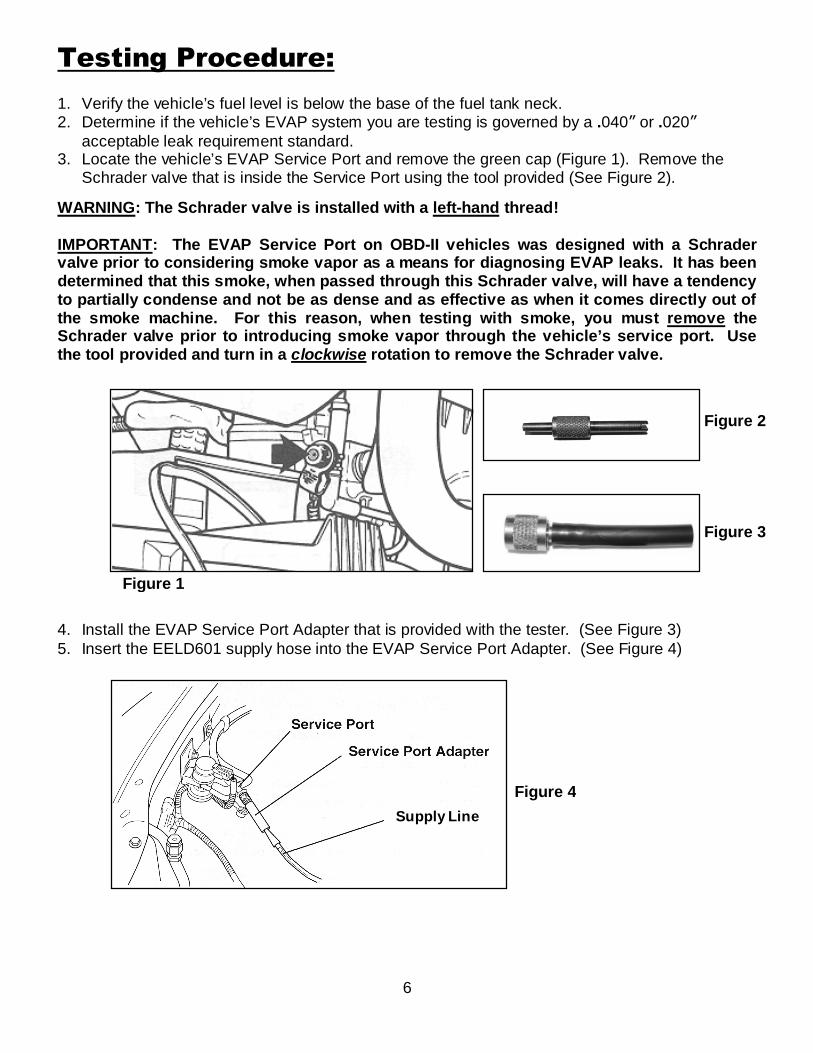
Testing Procedure:
1. Verify the vehicle’s fuel level is below the base of the fuel tank neck.2. Determine if the vehicle’s EVAP system you are testing is governed by a .040” or .020”
acceptable leak requirement standard.3. Locate the vehicle’s EVAP Service Port and remove the green cap (Figure 1). Remove the
Schrader valve that is inside the Service Port using the tool provided (See Figure 2).
WARNING: The Schrader valve is installed with a left-hand thread!
IMPORTANT: The EVAP Service Port on OBD-II vehicles was designed with a Schradervalve prior to considering smoke vapor as a means for diagnosing EVAP leaks. It has beendetermined that this smoke, when passed through this Schrader valve, will have a tendencyto partially condense and not be as dense and as effective as when it comes directly out ofthe smoke machine. For this reason, when testing with smoke, you must remove theSchrader valve prior to introducing smoke vapor through the vehicle’s service port. Usethe tool provided and turn in a clockwise rotation to remove the Schrader valve.
4. Install the EVAP Service Port Adapter that is provided with the tester. (See Figure 3)5. Insert the EELD601 supply hose into the EVAP Service Port Adapter. (See Figure 4)
Figure 2
Figure 1
Supply Line
Figure 3
Figure 4

7
To Charcoal Canister
Note: When testing a vehicle without an EVAP Service Port; you will need toaccess the EVAP system by disconnecting the EVAP line from the EVAP PurgeValve leading to the charcoal canister. (See Figure 5)
A. Locate the EVAP Purge Valve.B. Disconnect the line, at the EVAP Purge Valve, that leads back to the charcoal canister..C. Insert the smoke supply line into the line that you just removed from the EVAP Purge Valve
as shown below.
Note: Be sure you have a leak-tight secure fit, otherwise a leak at that connection may fool youinto thinking you have a leak in the system you are testing.
EVAP Purge Valve(Vapor Management Valve)
Figure 5

8
Testing Procedure (continued):
6. Press and release the ON / OFF button to activate the EELD601. The tester’s red Smoke lightwill turn ON, indicating smoke production. Notice that at the beginning of the test procedure, theflowmeter's indicator-ball will go to the top of the flow meter scale. This indicates two things; (a)the EVAP System is being filled and (b) there is no restriction in the EVAP system at this time.> If the ball initially never goes to the top of the flow meter, this indicates a restriction in theEVAP system. (Did you remember to remove the Schrader valve from the EVAP service port?)
7. Now close the vehicle’s EVAP System Vent Solenoid. Usually in less than 60 seconds ofactivating / closing the vent solenoid -- depending on capacity and fuel system level -- the flowmeter's indicator-ball will fall within the meter’s visible scale
8. Continue to fill the system until the ball stops descending. This could take an additionaltwo minutes.> The timer will automatically turn OFF in five minutes. To turn the tester OFF before the5-minutes are up, simply press the ON / OFF button again.
9. Once the meter's indicator-ball stops descending, align flow meter’s red flag to the indicator-ball(Figure 6). If the ball descends to the bottom of the meter, this indicates the system has NOleak. However, if the red flag indicates a leak greater than the allowable standard, continue tointroduce smoke into the system and look for the smoke or dye exiting the leak.
Helpful Tip: You will find that a common leak in the vehicle's EVAP System is due to an unsecured or faulty fuel cap.For this reason, we recommend you do not disturb the vehicle's fuel cap before you test the system for leaks. Thisway if an unacceptable leak has been determined, you can reposition or test the fuel cap, then perform the EVAP testagain. If you discover the leak was due to a faulty fuel cap, you will have been able to identify with the symptom.Otherwise if you disturb the fuel cap prior to performing your test, and the vehicle passes the test, you will never knowfor sure if the leak was due to the fuel cap or if you are dealing with an intermittent condition.
> If it has been determined that the vehicle you are testing has FAILED the leak test, then use the halogenlight provided and look for smoke exiting a leak, or shine a UV light (not provided) to see the dye deposited at
the leak point(s).
A measurement ABOVE the .020”or .040” indicator means anunacceptable leak in the EVAPSystem for that particular leakstandard (FAIL). (See Figure 6)
A measurement BELOW the .020”or .040” indicator means anacceptable leak (or no leak) in theEVAP System (PASS).
Figure 6
1
2
3
4
5
6
7
8
9
10
.040” FAILabove this line
ApproximatePass / Fail Line
.020” FAILabove this line
ApproximatePass / Fail Line
For intermittent leaks, watch the ball in the flow meter while doing awiggle test on the EVAP system components (hoses connections,etc.) If the ball in the flow meter goes up only when you wiggle acomponent, this indicates an intermittent leak. Continue to introducesmoke into the system and look for the leak. Repair the leak andretest.

9
Other Leak Detection Applications:
1. Vacuum and Induction Leaks: Select the correct size cap plug (supplied) to seal the system –but do not seal the system yet. (You should first purge all the non-smoke air out of the systembeing tester before you seal the system with the cap plug).> It is best to seal the engine’s intake as close to the air inlet origin as possible to inspect theentire system. This is especially important on engines equipped with mass airflow sensors andrelated ducting connecting it to the intake system. If the system you are testing cannot besealed with the kit we have provided, it will become necessary to seal the intake by othermeans. For example; wrap the vehicle’s air filter with cellophane and reinstall into the air filterhousing and secure. The cellophane will prevent most of the smoke from exiting the intakesystem, allowing you to create a satisfactory seal in the system you are testing for leaks. Oryou may choose to use a latex rubber glove and a strong rubber band to accomplish this task.Simply stretch the wrist of the glove around the air passage and secure with the rubber band.You may choose to plug the tail pipe of the vehicle with the exhaust cone that is provided -- besure the exhaust cone’s hose is also plugged. (It is possible that smoke pressure can be lostout the exhaust if both an intake and exhaust valve are open in the same cylinder at the sametime).
2. Select a vacuum line on the engine that is easily accessible and insert the tapered brass nozzleinto this line.> The supply line to the brake booster is a good choice when introducing smoke into the intakemanifold. It is important to make sure that you enter this line at a point where the check valvewill not interfere with the smoke flow.
3. Press the ON / OFF button once to turn the tester ON. Let the tester run until the system isfilled with smoke. (30 seconds to 1 minute is usually sufficient time to fill the induction system).
4. Seal the system once smoke is observed exiting a leak.
5. Turn the tester ON and OFF in 30-second intervals until you pinpoint the leak – or at an intervalthat will allow the smoke pressure to decrease in order to see the smoke even more easily.
6. Use the halogen light supplied to identify the origin of the smoke or use a UV light (notsupplied) to look for residual traces of the fluorescent dye that was left behind by the smoke.
Vacuum and induction leaks. Exhaust leaks. EGR valve leaks. Oil seals and gasket leaks. Idle motors and solenoid leaks.
Brake booster leaks. Component testing (radiators, water pumps
and valves). Under dash leaks. Intercooler and turbo charger leaks. Wind and water leaks (windows & sunroofs).
Install cap plug(supplied) aftersmoke has filledthe system.
Introduce smoke through an easilyaccessible vacuum line.

10
Carbureted Engines and Typical Leak Sources
Fuel Injected Engines and Typical Leak Source

11
Exhaust Leaks: Escaping exhaust gases can be very toxic to the occupants of a vehicle yetthese repairs are neglected — but so easy to find with the EELD601.
EGR Valve Leaks: The exhaust gas re-circulating (EGR) valve is at the heart of the emissioncontrol system. Since the EGR valve operates in such a hostile environment it is alwayssusceptible to leakage. During a normal test for vacuum leaks, the EGR valve will be exposed tosmoke and may show leaks at the seat, diaphragm, or even the base gasket.
If smoke is seen exiting the EGR valve, disconnect the vacuum supply line and introduce smokedirectly into the valve. This will verify if the diaphragm is leaking, or if the valve is leaking at theseat.
Smoke may also be used to check the EGR ports for restriction. Open or remove the valve andintroduce smoke through the tail pipe to verify that these ports are open.
Tech Tip - Testing the EGR Pintle Shaft: This will help you diagnose a good or bad EGR valveand other “metered” leaks.
1. Do not cap off any part of the engine – leave it in normal operating state (but NOT running).Insert the EELD601 supply hose into a direct vacuum manifold source, such as a brakebooster hose or PCV. Turn the tester ON. Watch for smoke to escape from the EGR valve.If you see a lot of smoke, move on to the next step.
2. Cap off the intake using one of the cap plugs supplied with the EELD601. Insert the exhaustcone into the tailpipe. (The hose on the exhaust cone should be plugged with the cap plugprovided.) Now that the system is sealed, press the remote button and watch for smoke. Asmall amount of smoke indicates an acceptable EGR valve.
Figure 7
1. Put the vehicle on a lift to expose the underside.With the engine off, simply insert the exhaustadapter cone into the tail pipe of the vehicle beingtested (Figure 7). Insert the smoke supply linenozzle into the exhaust cone’s hose opening andpress the ON / OFF button.> On dual exhaust systems, install a cone in each tailpipe. Be sure one cone is plugged.> Most exhaust systems will fill in less than twominutes.
2. Look for the smoke exiting wherever there is a leak.3. Even though exhaust leaks are very easy to find with
EELD601, here are two helpful tips to make findingexhaust leaks even easier:(a) It is best to test a cold exhaust system rather thana hot one. A very hot catalytic converter mayconsume some of the smoke. But most importantly,many small exhaust leaks are only visible on a coldexhaust system due to ‘thermal expansion’.(b) Seal off the vehicle’s intake system in order toachieve proper system pressure in the event both anintake and exhaust valve are open in the samecylinder at the same time.

12
Oil Seals and Gasket Leaks: Many oil leaks can be located with the EELD601. It is important tounderstand that the EELD601 will only find leaks that will allow air to flow through them. Example:A cam seal may allow air to pass through whereas a drain plug or pressure sensor will not. Tolocate oil leaks it is necessary to pressurize the crankcase with smoke.
1. Remove the dipstick and slip a hose over the dipstick tube, and insert the smoke supplynozzle into the hose.
2. Plug the PCV, air breather, and intake. Remove the oil filler cap.3. Introduce smoke into the crankcase until smoke is seen exiting the oil filler port.4. Install the oil filler cap and continue filling the system.5. Use the spotlight to check for leaks, which could appear as seeping smoke, bubbling oil with
little or no smoke, or dripping oil with no smoke at all.
Brake Booster Leaks: A leaking vacuum brake booster not only effects engine performance likeother types of vacuum leaks, but more importantly, it can seriously affect the stopping power of thevehicle. The brake booster is a simple component to check for leaks.
1. Disconnect the vacuum supply line and the check valve from the brake booster.2. Insert the smoke supply nozzle into the brake booster and begin introducing smoke.3. Under the hood, look for smoke exiting around the crimped area of the booster canister.
Also look inside the vehicle under the dash.NOTE: Do not depress the brake pedal while performing this test.
Component Leak Testing (radiators, water pumps, valves, etc.): When installing new or rebuiltparts nothing is more frustrating than to discover on completion of the job that the component isfaulty, or has a leak. It is far easier to inspect a radiator or water pump before it is installed than tofind out after the job is completed and the antifreeze/coolant is installed, that there is a leak.Component leak testing has endless possibilities; anything from hoses to diaphragms can betested. Supplied with every EELD601 is an exhaust cone adapter that can be used to access anyopening from 1" to 3-½". Simply introduce smoke into the system being tested, allow to fill withsmoke, then seal any inter-connecting ports or passages and look for the smoke or dye at exitpoints.
Under Dash Leaks: Under dashboard leaks can be very difficult to locate without a smokemachine. The EELD601 can confirm or eliminate the possibility of an under dash leak in minutes.Most vehicles have a common vacuum supply line that originates at the engine intake. Thisvacuum source comes through the firewall to supply the climate control functions as well as othersystems in the vehicle. Vacuum systems under the dashboard are intended to be closed systems;any flow through these systems would indicate that there is a leak present.
1. Connect the supply nozzle to the main vacuum line (beyond the check valve) leading to thedashboard.
2. Introduce smoke into the system and watch the flow meter’s indicator ball. If the ball dropsto zero the system is leak-free.
3. Continue to introduce smoke into the system while testing each setting on the climatecontrol. Watch the flow meter, as you change the climate control settings, for any indicationof flow confirming a leak.
4. Continue to introduce smoke into the position determined to have a leak. Use the spotlightto look for the smoke exiting the leak, or use a UV lamp to look for the dye deposited.

13
Intercooler and Turbo Charger Leaks: Engine compartments with turbochargers tend to runhotter than normally aspirated engines causing hoses and seals to dry out and leak. Forturbocharged systems to operate efficiently there can be no leaks in the intercooler, ducting,exhaust or the turbo itself. Intercoolers and turbochargers are tested with the engine off, as with alltests performed with the EELD601.
1. Connect the smoke supply line to the intake system.2. Introduce smoke into the “cold” side of the turbocharger.3. While the intake is under smoke pressure, inspect the intercooler, the ducting, the waste
gate, and the cold side of the turbo for leaks.4. To inspect the “hot” side or exhaust side of the turbo for leaks, install the exhaust cone into
the exhaust pipe. Introduce smoke and inspect the exhaust, the exhaust manifold, and thehot side of the turbocharger.
Wind and Water Leaks from sunroofs, windows and windshields: One of the toughest leaks tofind on an automobile is wind / water leaks around the doors, windows, and sunroofs or into thetrunk compartment. It isn’t safe or practical to search for these leaks while driving at 65 M.P.H.although that is when they are most noticeable. Old fashioned ways of locating where the windand water is entering the vehicle may identify the leak, but this does not locate the origin of theleak, as you can with EELD601.
1. Park the vehicle in an area that is shielded from the wind (preferably inside a closed facility).2. Turn the vehicle’s ignition to the ACCESSORIES position.3. Turn the heater/AC blower to FRESH AIR and HIGH. (Verify the blower is NOT set to the
recirculation mode.)4. Close the vehicle’s doors and windows. The cabin of the vehicle is now under a slight
positive pressure.5. Attach the Diffuser (available as an optional accessory) to the end of the tester’s hose.
(See Figure 8)6. Turn the tester ON with the selector switch set to SMOKE.7. From outside the vehicle, position the tip of the diffuser about 2 – 3 inches away from the
vehicle, and follow a path along the areas you wish to test. The smoke will linger on thepath you are following until a leak is present. The air exiting the vehicle will cause thesmoke to be disrupted, identifying the source of the leak.
Figure 8
Diffuser

14
Calibrating System-Pressure:
The EELD601 has been calibrated at the factory andadjusting the tester’s supply pressure is NOTrecommended as part of any scheduled maintenance.However, most OEMs require that an EVAP-approved testerhave a calibrating option, so the ability to calibrate the testerin the field has been provided for you.
Confirming if the tester needs adjustment
1. For calibration purposes, you will need a water columnpressure gauge reading in inches of water (H2O) (suchas Vacutec part # 060-30IW), not inches of mercury (Hg).
2. Connect tester to air pressure.3. Connect tester to 12-volt power.4. Connect tester’s supply hose to the water column gauge.5. Press tester’s ON/OFF button to turn tester ON.6. Read water column gauge. Be sure it is between 13”-
14”.7. Proceed to step 8 if the tester’s pressure is not between
13”-14” (H2O).
Adjusting System Pressure
8. Remove the plastic cap covering the tester’s adjuster.(See figure 11)
9. Be sure you have performed steps 1-6 above and thatyou are now on step 6 with the tester ON.
10. Use a flat-blade screwdriver to adjust the systempressure between 13”-14” H2O (See figure 12).
CAUTION: Carefully adjust the systempressure regulator by turning the adjuster inonly 1/8 turns at a time. Turning the regulatorplunger too far clockwise will cause theplunger to lock up; turning the regulatorplunger too far counterclockwise will cause theplunger and spring to fall out of the regulator.
!
11.Disconnect the tester’s supply hose from the calibrationgauge and reconnect it again. Verify that systempressure is between 13”-14” H2O; if not, repeat steps 9and 10, as necessary.
12.Turn tester OFF.13.Replace the plastic cap as shown on Figure 11.
Figure 10
Calibration GaugePart No. 060-30IW
(not supplied)
Figure 11
Figure 12

15
Troubleshooting:
The EELD601 is controlled by a sophisticated microprocessor controller. Below is a chartdescribing some of the diagnostic light functions.
Diagnostic Lights
Troubleshooting Guide
Symptom Likely Cause Solution
The green powerindicator lamp on thetester does not comeON.
1. The power cables arereversed.
2. Poor power-supply cableconnection.
3. Battery providing power is tooweak.
1. Correctly position the power cables.
2. Secure the connection at the positiveterminal and chassis ground.
3. Verify the battery is in good conditionand fully charged.
I turn the tester ON butthere is no air or smokecoming out of the supplyhose.
1. Tester is not connected toinert gas or shop air.
2. Poor power-supply cableconnection.
3. Battery providing power is tooweak.
1. Connect tester to gas or shop air.
2. Secure the connection at the positiveterminal and chassis ground.
3. Verify the battery is in good conditionand fully charged.
Smoke does NOT comeout of the vehicle’s fuelneck area when fillingthe EVAP system.
1. Fuel tank level is too high andis blocking the fuel neckpassage.
1. Reduce the fuel level in the tank so itis below the base of the fuel tank neck.
Green Red Interval Probable Cause Constant ON Sufficient battery power Blinks every one (1) second Insufficient battery power
Blink simultaneously every one (1) second
Power connection at battery isloose or there is short in heatingcircuit (could also be bad groundor power connection at smokecanister )
Blink simultaneously @ 4 blinks per secondOpen heating circuit (could alsobe bad ground connection atsmoke canister)
Blink alternately @ 1 blink per second Circuit board failure ٭
٭ If this occurs; first try disconnecting power to the tester for 10 seconds; then reconnect power. If this failurecode occurs a second time during operation, disconnect tester and contact manufacturer.

16
Contact Info:
See your tool dealer to order smoke solution or accessories.
To speak to Technical Support:
1-888-822-8832 (Option 2)
In the unlikely event this product has a problem,we would like you to contact the manufacturer directly.This will insure a faster handling of your service needs.
Manufacturer:
Worldwide Vapor, Inc.Tel - 1.888.822-8832 (Option 2) or 714.438.1387
Fax - 714.433.2840

17
Frequently Asked Questions for models EELD601 & EVAPro 2000E:
Why do I need a special smoke machine like this Vacutec®?The Vacutec® smoke machine contains smoke technology approved by the OEMs for EVAP and othertesting. Extensive tests were conducted to make sure the smoke vapor (and the dye marker in the vapor)did not harm any vehicle components – especially the EVAP’s activated charcoal. OEMs have determinedthat this patented technology is safe to use in their vehicles and will not void their vehicle factory warranties.This technology was also designed so that the smoke vapor could be produced with Nitrogen, in order tomeet the OEMs’ and industry safety requirements for EVAP testing. Additional safety features are built in.
Why should I use Nitrogen when testing an EVAP system?Adding air containing 21% oxygen to a vehicle’s vapor space can render it flammable. Only a volume of11% oxygen is required to sustain combustion. See SAE document http://www.sae.org/technical/papers/2007-01-1235
I’ve heard some people say that the “OEM-Approved” smoke solution (oil) is the same as genericmineral oil, such as “baby oil”, is that true?No, that is not true. Doing a very simple comparative analysis of two oils to merely determine what the basic‘source’ of the oil is can be very misleading. Most non-synthetic oils are of a “petroleum” base and manycan be categorized as being a “mineral oil”, but the end product can be significantly different. Upon closeranalysis the truth is revealed. The oil that has been approved by all automakers using smoke technology isnot “baby oil”. In fact, even baby oil manufacturers say that baby oil is not intended for industrial use. TheOEM-Approved oil is a highly refined mineral oil-based solution; blended in a special formula to be able towithstand the high temperatures during the oil's vaporization process; has been designed not to harmcomponents; is patented and approved by all automakers using smoke technology. There are twoapproved solutions; the standard solution and the more popular UltraTraceUV® which contains dye.
Why didn’t you incorporate a pressure gauge into the machine for testing pressure-decay?
Pressure decay has serious limitations and cannot indicate a 0.040” / 0.020” leak. With pressure decay youcould be wasting your time looking for a leak that didn't cause that MIL lamp problem you are trying to fix.It’s best to use the machine’s flow meter and calibrate for an exact leak size.
Why doesn’t this smoke machine offer a way to adjust the smoke delivery pressure?One major safety feature requirement was to design the machine so that its delivery pressure was notadjustable. That avoids mistakes of setting the pressure to dangerous levels when testing EVAP systems.
Why doesn’t this smoke machine offer a way to adjust the smoke volume?Adjusting the smoke volume (or flow) merely reduces the amount of smoke the machine can flow and doeslittle to assist in finding leaks. Leaks are easier to see by reducing the pressure of the smoke in the systembeing tested, not by reducing the volume of the smoke while maintaining the same pressure. A simple wayto reduce the pressure in the system being tested is to toggle the smoke machine OFF for a few secondsafter filling. That reduces the pressure in the system, making smoke exiting a small leak even easier to see.
In operating the tester, how can I be sure I am not connected to a plugged or restricted line andthink I am introducing smoke into the system being tested but really I am not?Simply by looking at the flow meter. If the flow meter’s ball is at zero, that indicates there is no flow.
How long will the tester continue generating smoke?One 16-oz. container should last about 500 tests. However, you should top off the solution level regularly.
Does the EELD601 require any assembly?NO! The tester arrives ready for work, fully assembled and with a full charge of smoke-producing solution.Simply connect it to shop air or nitrogen and 12-volt DC power.
Wouldn’t a smoke machine that generates a higher smoke pressure detect leaks better?First of all, the pressure this tester delivers has been determined by the automotive industry as the requiredpressure when testing their EVAP systems and must not be exceeded. In addition, trying to detect a leakwith vapor/smoke pressure much higher than this tester is actually less effective. The lower the smokepressure, the more visible the smoke becomes.

1
Warranty:
LIMITED TWO (2) YEAR WARRANTYManufacturer Model Numbers: Vacutec® EVAPro 2000E & EELD601
Worldwide Vapor, Inc. warrants the Vacutec® to the Original Purchaser that under normal use, care and service, theEquipment (except as otherwise provided herein) shall be free from defects in material and workmanship for TWOYEARS from the date of original invoice.
This Warranty does not cover (and separate charges for parts, labor and related expenses shall apply to) any damage to,malfunctioning, inoperability or improper operation of the Equipment caused by, resulting from or attributable to (A) abuse,misuse or tampering; (B) alteration, modification or adjustment (other than calibration) of the Equipment; (C) installation, repairor maintenance (other than specified operator maintenance) of the Equipment or related equipment, attachments, peripheralsor optional features by other than Seller's authorized representatives; (D) improper or negligent use, application, operation,care, cleaning, storage or handling; (E) fire, water, wind, lightning or other natural causes; (F) adverse environmentalconditions, including, without limitation, excessive heat, moisture, corrosive elements, or dust or other air contaminants; radiofrequency interference; electric power failure; power line voltages beyond those specified for the Equipment; unusual physical,electrical or electro-magnetic stress; and/or any other condition outside of Seller's environmental specifications; (G) use of theEquipment in combination or connection with other equipment, attachments, supplies or consumables not manufactured orsupplied by Seller.
NO OTHER WARRANTIES, EXPRESS, IMPLIED OR STATUTORY, INCLUDING WITHOUT LIMITATION ANY IMPLIEDWARRANTY OF MERCHANTABILITY OR FITNESS FOR A PARTICULAR PURPOSE, SHALL APPLY, AND ALL SUCHWARRANTIES ARE HEREBY EXPRESSLY EXCLUDED.
Seller's obligations under this warranty are limited solely to the repair or, at Seller's option, replacement of or refund of theoriginal purchase price for, Equipment or parts which to Seller's satisfaction are determined to be defective and which arenecessary, in Seller's judgment, to return the equipment to good operating condition.
Repairs or replacements qualifying under this Warranty will be performed or made on regular business days during Seller'snormal working hours within a reasonable time following Buyer's request. All requests for warranty service must be madeduring the stated warranty period.
This product contains licensed technology:
Form No. 500-OMEELD601 Rev 01/07/08
18