Embed Size (px)
Citation preview

OPERATOR’SMANUAL
Model 340, 341, 342Slush Freezers
Original Operating Instructions
028764-M1/97 (Original Publication)
(Updated 6/29/15)

Complete this page for quick reference when service is required:
Taylor Distributor:
Address:
Phone:
Service:
Parts:
Date of Installation:
Information found on the data label:
Model Number:
Serial Number:
Electrical Specs: Voltage Cycle
Phase
Maximum Fuse Size: A
Minimum Wire Ampacity: A
E 1997 Carrier Commercial Refrigeration, Inc.028764-MAny unauthorized reproduction, disclosure, or distribution of copies by any person of any portion of this work may bea violation of Copyright Law of the United States of America and other countries, could result in the awarding of StatutoryDamages of up to $250,000 (17 USC 504) for infringement, and may result in further civil and criminal penalties.All rights reserved.
Taylor Companya division of Carrier Commercial Refrigeration, Inc.750 N. Blackhawk Blvd.Rockton, IL 61072

Models 340, 341, 342 Table of Contents
Table of Contents
Section 1 To the Installer 1. . . . . . . . . . . . . . . . . . . . . . . . . . . . . . . . . . . . . . . . . . . .
Installer Safety 1. . . . . . . . . . . . . . . . . . . . . . . . . . . . . . . . . . . . . . . . . . . . . . . . . . . . . . . .
Site Preparation 1. . . . . . . . . . . . . . . . . . . . . . . . . . . . . . . . . . . . . . . . . . . . . . . . . . . . . . .
Water Connections (Water Cooled Units Only) 2. . . . . . . . . . . . . . . . . . . . . . . . . . . .
Air Cooled Units 2. . . . . . . . . . . . . . . . . . . . . . . . . . . . . . . . . . . . . . . . . . . . . . . . . . . . . . .
Electrical Connections 2. . . . . . . . . . . . . . . . . . . . . . . . . . . . . . . . . . . . . . . . . . . . . . . . .
Beater Rotation 3. . . . . . . . . . . . . . . . . . . . . . . . . . . . . . . . . . . . . . . . . . . . . . . . . . . . . . .
Refrigerant 3. . . . . . . . . . . . . . . . . . . . . . . . . . . . . . . . . . . . . . . . . . . . . . . . . . . . . . . . . . .
Section 2 To the Operator 4. . . . . . . . . . . . . . . . . . . . . . . . . . . . . . . . . . . . . . . . . . .
Section 3 Safety 5. . . . . . . . . . . . . . . . . . . . . . . . . . . . . . . . . . . . . . . . . . . . . . . . . . . .
Section 4 Operator Parts Identification 7. . . . . . . . . . . . . . . . . . . . . . . . . . . . . . .
Model 340 7. . . . . . . . . . . . . . . . . . . . . . . . . . . . . . . . . . . . . . . . . . . . . . . . . . . . . . . . . . . .
Model 341 8. . . . . . . . . . . . . . . . . . . . . . . . . . . . . . . . . . . . . . . . . . . . . . . . . . . . . . . . . . . .
Model 342 9. . . . . . . . . . . . . . . . . . . . . . . . . . . . . . . . . . . . . . . . . . . . . . . . . . . . . . . . . . . .
Models 340, 341, 342 Beater Door Assembly (Standard Door/No Prime Plug) 10.
Model 342 Beater Door Assembly With Self- Closing/Prime Plug Door 11. . . . . . .
Section 5 Important: To the Operator 14. . . . . . . . . . . . . . . . . . . . . . . . . . . . . . . . .
Symbol Definitions 14. . . . . . . . . . . . . . . . . . . . . . . . . . . . . . . . . . . . . . . . . . . . . . . . . . . .
Control Switch 14. . . . . . . . . . . . . . . . . . . . . . . . . . . . . . . . . . . . . . . . . . . . . . . . . . . . . . . .
Consistency Control 14. . . . . . . . . . . . . . . . . . . . . . . . . . . . . . . . . . . . . . . . . . . . . . . . . . .
Indicator Light - “Add Mix” 14. . . . . . . . . . . . . . . . . . . . . . . . . . . . . . . . . . . . . . . . . . . . . .
For Your Information 14. . . . . . . . . . . . . . . . . . . . . . . . . . . . . . . . . . . . . . . . . . . . . . . . . . .
Section 6 Operating Procedures 15. . . . . . . . . . . . . . . . . . . . . . . . . . . . . . . . . . . . .
Assembly 15. . . . . . . . . . . . . . . . . . . . . . . . . . . . . . . . . . . . . . . . . . . . . . . . . . . . . . . . . . . .
Sanitizing 24. . . . . . . . . . . . . . . . . . . . . . . . . . . . . . . . . . . . . . . . . . . . . . . . . . . . . . . . . . . .
Priming 25. . . . . . . . . . . . . . . . . . . . . . . . . . . . . . . . . . . . . . . . . . . . . . . . . . . . . . . . . . . . . .
Closing Procedure 26. . . . . . . . . . . . . . . . . . . . . . . . . . . . . . . . . . . . . . . . . . . . . . . . . . . .
Draining Product From the Freezing Cylinder 27. . . . . . . . . . . . . . . . . . . . . . . . . . . . .

Table of Contents Models 340, 341, 342
Table of Contents - Page 2
Rinsing 27. . . . . . . . . . . . . . . . . . . . . . . . . . . . . . . . . . . . . . . . . . . . . . . . . . . . . . . . . . . . . .
Cleaning 28. . . . . . . . . . . . . . . . . . . . . . . . . . . . . . . . . . . . . . . . . . . . . . . . . . . . . . . . . . . . .
Disassembly 29. . . . . . . . . . . . . . . . . . . . . . . . . . . . . . . . . . . . . . . . . . . . . . . . . . . . . . . . . .
Brush Cleaning 29. . . . . . . . . . . . . . . . . . . . . . . . . . . . . . . . . . . . . . . . . . . . . . . . . . . . . . .
Section 7 Important: Operator Checklist 30. . . . . . . . . . . . . . . . . . . . . . . . . . . . . .
During Cleaning and Sanitizing 30. . . . . . . . . . . . . . . . . . . . . . . . . . . . . . . . . . . . . . . . .
Troubleshooting Bacterial Count 30. . . . . . . . . . . . . . . . . . . . . . . . . . . . . . . . . . . . . . . .
Regular Maintenance Checks 30. . . . . . . . . . . . . . . . . . . . . . . . . . . . . . . . . . . . . . . . . . .
Winter Storage 31. . . . . . . . . . . . . . . . . . . . . . . . . . . . . . . . . . . . . . . . . . . . . . . . . . . . . . . .
Section 8 Troubleshooting Guide 32. . . . . . . . . . . . . . . . . . . . . . . . . . . . . . . . . . . .
Section 9 Parts Replacement Schedule 35. . . . . . . . . . . . . . . . . . . . . . . . . . . . . . .
Section 10 Limited Warranty on Equipment 36. . . . . . . . . . . . . . . . . . . . . . . . . . . .
Section 11 Limited Warranty on Parts 38. . . . . . . . . . . . . . . . . . . . . . . . . . . . . . . . .
Note: Continuing research results in steady improvements; therefore, informationin this manual is subject to change without notice.
Note: Only instructions originating from the factory or its authorized translationrepresentative(s) are considered to be the original set of instructions.
E 1997 Carrier Commercial Refrigeration, Inc. (Original Publication)(Updated June, 2015)028764-MAny unauthorized reproduction, disclosure, or distribution of copies by any person of any portion of this workmay be a violation of Copyright Law of the United States of America and other countries, could result in theawarding of Statutory Damages of up to $250,000 (17 USC 504) for infringement, and may result in furthercivil and criminal penalties.All rights reserved.
Taylor Companya division of Carrier Commercial Refrigeration, Inc.750 N. Blackhawk Blvd.Rockton, IL 61072

1Models 340, 341, 342 To the Installer
131122
Section 1 To the Installer
The following information has been included in themanual as safety and regulatory guidelines. Forcomplete installation instructions, please see theInstallation Checklist.
Installer Safety
In all areas of the world, equipment should beinstalled in accordance with existing local codes.Please contact your local authorities if you have anyquestions.
Care should be taken to ensure that all basic safetypractices are followed during the installation andservicing activities related to the installation andservice of Taylor equipment.
S Only authorized Taylor service personnelshould perform installation and repairs on theequipment.
S Authorized service personnel should consultOSHA Standard 29CFRI910.147 or theapplicable code of the local area for theindustry standards on lockout/tagoutprocedures before beginning any installationor repairs.
S Authorized service personnel must ensurethat the proper PPE is available and wornwhen required during installation and service.
S Authorized service personnelmust remove allmetal jewelry, rings, and watches beforeworking on electrical equipment.
The main power supply(s) to the machinemust be disconnected prior to performing any repairs.Failure to follow this instruction may result in personalinjury or death from electrical shock or hazardousmoving parts as well as poor performance or damageto the equipment.
Note: All repairs must be performed by anauthorized Taylor Service Technician.
This unit has many sharp edges that cancause severe injuries.
Site Preparation
Review the area where the unit will be installed beforeuncrating the unit. Make sure all possible hazards tothe user or equipment have been addressed.
For Indoor UseOnly: This unit is designed to operateindoors, under normal ambient temperatures of70_-75_F (21_-24_C). The freezer has successfullyperformed in high ambient temperatures of104_(40_C) at reduced capacities.
This unit must NOT be installed in an areawhere a water jet or hose can be used. NEVER use awater jet or hose to rinse or clean the unit. Failure tofollow this instruction may result in electrocution.
This unit must be installed on a level surfaceto avoid the hazard of tipping. Extreme care should betaken in moving this equipment for any reason. Two ormore people are required to safely move this unit.Failure to comply may result in personal injury orequipment damage.
Uncrate the unit and inspect it for damage. Report anydamage to your Taylor Distributor.
This piece of equipment is made in the USA and hasUSA sizes of hardware. All metric conversions areapproximate and vary in size.

2 Models 340, 341, 342To the Installer
110105
Water Connections(Water Cooled Units Only)
An adequate cold water supply with a hand shut-offvalve must be provided. On the underside of the basepan, two 3/8” I.P.S. (for single-head units) or two 1/2”I.P.S. (for double-head units) water connections forinlet and outlet have been provided for easy hook-up.1/2” inside diameter water lines should be connectedto the machine. (Flexible lines are recommended, iflocal codes permit.) Depending on local waterconditions, it may be advisable to install a waterstrainer to prevent foreign substances from cloggingtheautomaticwater valve. Therewill be only onewater“in” and one water “out” connection for bothdouble-head and single-head units. DO NOT install ahand shut-off valve on the water “out” line! Watershould always flow in this order: first, through theautomatic water valve; second, through thecondenser; and third, through the outlet fitting to anopen trap drain.
Air Cooled Units
The model 340 air cooled unit requires a minimum of6” (152 mm) of clearance around both sides of thefreezer. It is recommended to install a skirt to one sideof the unit, and to place the back of the unit against awall. The models 341 and 342 air cooled units requirea minimum of 3” (76 mm) of air clearance around allsides.
Failure to allow adequate clearance can reduce therefrigeration capacity of the freezer and possiblycause permanent damage to the compressor.
Electrical Connections
In the United States, this equipment is intended to beinstalled in accordance with the National ElectricalCode (NEC), ANSI/NFPA 70- 1987. The purpose ofthe NEC code is the practical safeguarding of personsand property from hazards arising from the use ofelectricity. This code contains provisions considerednecessary for safety. Compliance therewith andproper maintenance will result in an installationessentially free from hazard!
In all other areas of the world, equipment should beinstalled in accordance with the existing local codes.Please contact your local authorities.
FOLLOW YOUR LOCAL ELECTRICAL CODES!
Each freezer requires one power supply for each datalabel. Check the data label(s) on the freezer for branchcircuit overcurrent protection or fuse, circuit ampacityand electrical specifications. For proper powerconnections, refer to the wiring diagram providedinside of the electrical box.
CAUTION: THIS EQUIPMENT MUST BEPROPERLY GROUNDED! FAILURE TO DO SOCAN RESULT IN SEVERE PERSONAL INJURYFROM ELECTRICAL SHOCK!
This unit is provided with an equipotentialgrounding lug that is to be properly attached to the rearof the frameby the authorized installer. The installationlocation is marked by the equipotential bondingsymbol (5021 of IEC 60417-1) on both the removablepanel and the equipment’s frame.

3Models 340, 341, 342 To the Installer
130919
S Stationary appliances which are not equippedwith a power cord anda plugor another deviceto disconnect the appliance from the powersource must have an all-pole disconnectingdevice with a contact gap of at least 3 mminstalled in the external installation.
S Appliances that are permanently connected tofixed wiring and for which leakage currentsmay exceed 10 mA, particularly whendisconnected, not used for long periods, orduring initial installation, shall have protectivedevices such as a GFI to protect against theleakage of current, installed by authorizedpersonnel to the local codes.
S Supply cords used with this unit shall beoil-resistant, sheathed flexible cable, notlighter than ordinary polychloroprene or otherequivalent synthetic elastomer-sheathed cord(Code designation 60245 IEC 57) installedwith the proper cord anchorage to relieveconductors from strain, including twisting, atthe terminals and protect the insulation of theconductors from abrasion.
If the supply cord is damaged, it must bereplaced by an authorized Taylor servicetechnician in order to avoid a hazard.
Beater Rotation
Beater rotation must be clockwise as viewedlooking into the freezing cylinder.
Note: The following procedures must beperformed by an authorized Taylor servicetechnician.
To correct rotation on a three-phase unit, interchangeany two incoming power supply lines at the freezermain terminal block only. To correct rotation on asingle-phase unit, change the leads inside the beatermotor. (Follow the diagram printed on the motor.)
Electrical connections are made directly to theterminal block. The terminal block is provided in themain control box located under the upper left sidepanel on counter models or behind the service panelon console models.
Refrigerant
In consideration of our environment, Tayloruses only earth friendly HFC refrigerants. The HFCrefrigerant used in this unit is R404A. This refrigerantis generally considered non-toxic and non-flammable,with an Ozone Depleting Potential (ODP) of zero (0).
However, any gas under pressure is potentiallyhazardous andmust be handled with caution. NEVERfill any refrigerant cylinder completely with liquid.Filling the cylinder to approximately 80% will allow fornormal expansion.
Use only R404A refrigerant that conforms tothe AHRI standard 700 specification. The use of anyother refrigerant may expose users and operators tounexpected safety hazards.
Refrigerant liquid sprayed onto the skin maycause serious damage to tissue. Keep eyes and skinprotected. If refrigerant burns should occur, flushimmediately with cold water. If burns are severe, applyice packs and contact a physician immediately.
Taylor reminds technicians to be cautious ofgovernment laws regarding refrigerant recovery,recycling, and reclaiming systems. If you have anyquestions regarding these laws, please contact thefactory Service Department.
WARNING: R404A refrigerant used inconjunction with polyolester oils is extremely moistureabsorbent. When opening a refrigeration system, themaximum time the system is openmust not exceed 15minutes. Cap all open tubing to prevent humid air orwater from being absorbed by the oil.

4 Models 340, 341, 342To the Operator
131122
Section 2 To the Operator
The freezer you have purchased has been carefullyengineered and manufactured to provide dependableoperation. TheTaylor SlushModels 340, 341, and342,when properly operated and cared for, will produce aconsistent quality product. Like all mechanicalproducts, these machines will require cleaning andmaintenance. A minimum amount of care andattention is necessary if the operating proceduresoutlined in this manual are followed closely.
This Operator’s Manual should be read beforeoperating or performing any maintenance on yourequipment.
Your Taylor freezer will NOT eventually compensateand correct for any errors during the set-up or fillingoperations. Thus, the initial assembly and primingprocedures are of extreme importance. It is stronglyrecommended that personnel responsible for theequipment’s operation study these procedurestogether in order to be properly trained and to makesure that no misunderstandings exist.
In the event you should require technical assistance,please contact your local authorized TaylorDistributor.
Note: Your Taylor warranty is valid only if the parts areauthorized Taylor parts, purchased from the localauthorized Taylor Distributor, and only if all requiredservice work is provided by an authorized Taylorservice technician. Taylor reserves the right to denywarranty claims on units or parts if non- Taylorapproved parts or incorrect refrigerant were installedin the unit, system modifications were performedbeyond factory recommendations, or it is determinedthat the failure was caused by abuse, misuse, neglect,or failure to follow all operating instructions. For fulldetails of your Taylor Warranty, please see the LimitedWarranty section in this manual.
Note: Constant research results in steadyimprovements; therefore, information in thismanual is subject to change without notice.
If the crossed out wheeled bin symbol isaffixed to this product, it signifies that this product iscompliant with the EUDirective as well as other similarlegislation in effect after August 13, 2005. Therefore,it must be collected separately after its use is
completed, and cannot be disposed as unsortedmunicipal waste.
The user is responsible for returning the product to theappropriate collection facility, as specified by your localcode.
For additional information regarding applicable locallaws, please contact the municipal facility and/or localdistributor.
Compressor Warranty Disclaimer
The refrigeration compressor(s) on this unit arewarranted for the term stated in the Limited Warrantysection in this manual. However, due to the MontrealProtocol and the U.S. Clean Air Act Amendments of1990, many new refrigerants are being tested anddeveloped, thus seeking their way into the serviceindustry. Some of these new refrigerants are beingadvertised as drop- in replacements for numerousapplications. It should be noted that in the event ofordinary service to this unit’s refrigeration system,only the refrigerant specified on the affixed datalabel should be used. The unauthorized use ofalternate refrigerants will void your Taylor compressorwarranty. It is the unit owner’s responsibility to makethis fact known to any technician he employs.
It should also be noted that Taylor does not warrant therefrigerant used in its equipment. For example, if therefrigerant is lost during the course of ordinary serviceto this machine, Taylor has no obligation to eithersupply or provide its replacement either at billable orunbillable terms. Taylor does have the obligation torecommend a suitable replacement if the originalrefrigerant is banned, obsoleted, or no longer availableduring the five year warranty of the compressor.
Taylor will continue to monitor the industry and testnew alternates as they are being developed. Should anew alternate prove, through our testing, that it wouldbe accepted as a drop-in replacement, then the abovedisclaimer would become null and void. To find out thecurrent status of an alternate refrigerant as it relates toyour compressor warranty, call the local TaylorDistributor or the Taylor Factory. Be prepared toprovide the Model/Serial Number of the unit inquestion.

5Models 340, 341, 342 Safety
130919
Section 3 Safety
We, at Taylor Company, are concerned about thesafety of the operatorwhen heor she comes in contactwith the freezer and its parts. Taylor has gone toextreme efforts to design and manufacture built-insafety features to protect both you and the servicetechnician. As an example, warning labels have beenattached to the freezer to further point out safetyprecautions to the operator.
IMPORTANT - Failure to adhere to thefollowing safety precautions may result in severepersonal injury. Failure to comply with thesewarnings may damage the machine and itscomponents. Component damage will result inpart replacement expense and service repairexpense.
To Operate Safely:
DONOT operate the freezer without readingthis Operator Manual. Failure to follow this instructionmay result in equipment damage, poor freezerperformance, health hazards, or personal injury.
This appliance is to be used only by trainedpersonnel. It is not intended for use by children orpeople with reduced physical, sensory, or mentalcapabilities, or lack of experience and knowledge,unless given supervision or instruction concerning theuse of the appliance by a person responsible for theirsafety. Children should be supervised to ensure thatthey do not play with the appliance.
This unit is provided with an equipotentialgrounding lug that is to be properly attached to the rearof the frameby the authorized installer. The installationlocation is marked by the equipotential bondingsymbol (5021 of IEC 60417-1) on both the removablepanel and the equipment’s frame.
S DO NOT operate the freezer unless it isproperly grounded.
S DO NOT operate the freezer with larger fusesthan specified on the freezer data label.
S All repairs must be performed by anauthorized Taylor service technician.
S Themain power supplies to the machinemustbe disconnected prior to performing anyrepairs.
S For Cord Connected Units: Only Taylorauthorized service technicians or licensedelectricians may install a plug or replacementcord on these units.
S Stationary appliances which are not equippedwith a power cord anda plugor another deviceto disconnect the appliance from the powersource must have an all-pole disconnectingdevice with a contact gap of at least 3 mminstalled in the external installation.
S Appliances that are permanently connected tofixed wiring and for which leakage currentsmay exceed 10 mA, particularly whendisconnected, not used for long periods, orduring initial installation, shall have protectivedevices such as a GFI to protect against theleakage of current, installed by authorizedpersonnel to the local codes.
S Supply cords used with this unit shall beoil-resistant, sheathed flexible cable, notlighter than ordinary polychloroprene or otherequivalent synthetic elastomer-sheathed cord(Code designation 60245 IEC 57) installedwith the proper cord anchorage to relieveconductors from strain, including twisting, atthe terminals and protect the insulation of theconductors from abrasion.
If the supply cord is damaged, it must bereplaced by an authorized Taylor servicetechnician in order to avoid a hazard.
Failure to follow these instructions may result inelectrocution. Contact your local authorized TaylorDistributor for service.

6 Models 340, 341, 342Safety
130919
DO NOT use a water jet to clean or rinse thefreezer. Failure to follow these instructions may resultin serious electrical shock.
S DONOT allow untrained personnel to operatethis machine.
S DONOT operate the freezer unless all servicepanels and access doors are restrained withscrews.
S DO NOT remove any internal operating parts(examples: freezer door, beater, scraperblades, etc.) unless all control switches are inthe OFF position.
Failure to follow these instructionsmay result in severepersonal injury to fingers or hands from hazardousmoving parts.
This unit has many sharp edges that cancause severe injuries.
S DO NOT put objects or fingers in the doorspout. This may contaminate the product andcause severe personal injury from bladecontact.
S USE EXTREME CAUTION when removingthe beater asssembly. The scraper blades arevery sharp.
This unit must be placed on a level surface.Extremecare should be takenwhenmoving theunit forany reason. Two or more persons are required tosafely move this unit. Failure to comply may result inpersonal injury or damage to the unit.
Access to the service area of the unit must berestricted to persons having knowledge and practicalexperience with the unit, in particular as far as safetyand hygiene are concerned.
Cleaning and sanitizing schedules aregoverned by your state or local regulatory agenciesand must be followed accordingly. Please refer to thecleaning section of this manual for the properprocedure to clean this unit.
This machine is designed to maintain producttemperature under 41_F (5_C). Any product beingadded to this machine must be below 41_F (5_C).Failure to follow this instruction may result in healthhazards and poor freezer performance.
DO NOT obstruct air intake and discharge openings:
Models 341/342: 3” (76mm)minimum air space on allsides.
Model 340: 6” (152 mm) minimum air space on sidesand 0” at the rear. It is recommended to install a skirtto one side of the unit, and to place the back of the unitagainst a wall.
Failure to follow this instruction may cause poorfreezer performance and damage to the machine.
For Indoor UseOnly: This unit is designed to operateindoors, under normal ambient temperatures of 70_ -75_F (21_ - 24_C). The freezer has successfullyperformed in high ambient temperatures of 104_F(40_C) at reduced capacities.
DO NOT run the unit without product. Failure to followthis instruction can result in damage to the unit.
NOISE LEVEL: Airborne noise emission does notexceed 78 dB(A) when measured at a distance of 1.0meter from the surface of the machine and at a heightof 1.6 meters from the floor.

7Models 340, 341, 342 Operator Parts Identification
150126
Section 4 Operator Parts Identification
Model 340
ITEM DESCRIPTION PART NO.
1 COVER A.- HOPPER- STD X38458- SER
2 GASKET- HOPPER COVER 038375
3 TUBE- FEED- NON REVERSE 015176- 9
4 PANEL- REAR 047008
5 LOUVER- SIDE- TOP 051192
6 PANEL- SIDE- RIGHT 047007
7 LEG- 4.250” 013458
ITEM DESCRIPTION PART NO.
8 SKIRT- AIR FLOW 049069
9 PAN- DRIP 19- 1/2 LONG 035034
10 TRAY- DRIP 14- 7/8L X 5- 1/8 013690
11 SHIELD- SPLASH 18” 022763
12 PANEL A.- FRONT X46881
13 PANEL- SIDE- LEFT 047006
14 PANEL- SIDE- UPPER 042317
NOTE: STANDARD DOOR SHOWN (NO PRIME PLUG)

8 Models 340, 341, 342Operator Parts Identification
150126
Model 341
ITEM DESCRIPTION PART NO.
1 COVER A.- HOPPER- STD X38458- SER
2 GASKET- HOPPER COVER 038375
3 TUBE- FEED- NON REVERSE 015176- 9
4 LOUVER- SIDE- TOP 051192
5 PANEL- UPPER SIDE 024576
6 PANEL- REAR 013637
7 PANEL A.- LOWER SIDE X24397- SER
8 TRIM- REAR CORNER 013620
9 ADAPTOR A.- CASTER X18915
10 CASTER- 4” SWV 5/8 STEM 018794
11 SCREW- 1/4- 20X3/8 SLTD 011694
12 ANGLE- PANEL- R 013828
ITEM DESCRIPTION PART NO.
13 CASTER- 4” SWV W/BRAKE 034081
14 PANEL- SERVICE 013638- SP1
15 PAN- DRIP 19- 1/2 LONG 035034
16 TRAY- DRIP 14- 7/8L X 5- 1/8 013690
17 SHIELD- SPLASH 18” 022763
18 ANGLE- PANEL- L 013829
19 PANEL A.- FRONT X46881
20 DECAL- DEC 048359
21 WASHER- PLASTIC PIVOT 013808
22 SCREW- 10- 24X1/2 TORX 002077
23 NUT- 10- 32 FLANGE LOCK 020983
24 SCREW- 10- 32X1/2 SERR. 020982
NOTE: STANDARD DOOR SHOWN (NO PRIME PLUG)

9Models 340, 341, 342 Operator Parts Identification
150126
Model 342
ITEM DESCRIPTION PART NO.
1 COVER A.- HOPPER- STD X38458- SER
2 GASKET- HOPPER COVER- 20 038375
3 TUBE- FEED- NON REVERSE 015176- 9
4 PANEL- REAR 017563
5 PANEL- SIDE *R 069037
6 TRIM- REAR CORNER- RIGHT 013663
7 ADAPTOR A.- CASTER X18915
8 CASTER- 4” SWV 5/8 STEM 018794
9 SCREW- 1/4- 20X3/8 SLTD 011694
10 ANGLE- PANEL- R 013828
ITEM DESCRIPTION PART NO.
11 CASTER- 4” SWV W/BRAKE 034081
12 PANEL- SERVICE 024439- SP1
13 TRAY- DRIP 22- 7/8L X 5- 1/8W 014533
14 SHIELD- SPLASH 037041
15 ANGLE- PANEL- L 013829
16 PANEL A.- FRONT X25807
17 DECAL- DEC- TAYLOR 021872
18 PAN- DRIP 11- 5/8 LONG 027503
19 PANEL- SIDE *L 069036
NOTE: STANDARD DOOR SHOWN (NO PRIME PLUG)

10 Models 340, 341, 342Operator Parts Identification
150126
Models 340, 341, 342 Beater Door Assembly (Standard Door/No Prime Plug)
ITEM DESCRIPTION PART NO.
1 DOOR A.- SLUSH- PARTIAL X83427SER3
2 HANDLE A.- DRAW- SLUSH X47384
3 VALVE- DRAW 047734
4 PIN A.- VALVE HANDLE X25929
5 O- RING- 1 OD x .139 W 032504
6 BUSTER- ICE 047735
7 O- RING- .291 ID x .080 W 018550
8 TORQUE A. X14488
9 BEARING- GUIDE 014496
10 GASKET- DOOR 5.177ID 016672
ITEM DESCRIPTION PART NO.
11 BEARING- FRONT 013116
12 BEATER A.- 7 QT- 1 PIN X46233
13 CLIP- SCRAPER BLADE*8.75 046238
14 ARM- TORQUE (340/341) 014500
ARM- TORQUE (342) 029549
15 SHAFT- BEATER 035418
16 SEAL- DRIVE SHAFT 032560
17 O- RING- 7/8 OD x .139 W 025307
18 NUT- STUD 029880
19 BLADE- SCRAPER- PLASTIC 046237

11Models 340, 341, 342 Operator Parts Identification
150427
Model 342 Beater Door Assembly With Self- Closing/Prime Plug Door

12 Models 340, 341, 342Operator Parts Identification
141118
Model 342 Beater Door Assembly With Self- Closing/Prime Plug Door
ITEM DESCRIPTION PART NO.
1 PIN- HANDLE- VALVE X83812
2 SPRING- COMP.970X.082 030344
3 VALVE- DRAW- SLF CLO 080662
4 O- RING- 1”OD X .139W 032504
5 BUSTER- ICE 047735
6
DOOR A.- PARTIALS/N M4106402 & UP
X83427- SER
DOOR W/PIN & VALVE S/NPRIOR TO M4106401
X83427SSP
7 O- RING- .563 OD X .070W 043758
8 PLUG- PRIME- STNLS 050405
9 HANDLE A.- DRAW- SLUSH X47384
10 NUT- STUD 029880
ITEM DESCRIPTION PART NO.
11 O- RING- .291 ID X .080W 018550
12 ARM- TORQUE 029549
13 TORQUE A. X14488
14 BEARING- GUIDE 014496
15 GASKET- DOOR 5.177ID 016672
16 BEARING- FRONT 013116
17 BEATER A.- 7QT- 1 PIN X46233
18 CLIP- SCRAPER BLADE 8.75” 046238
19 BLADE- SCRAPER- PLASTIC 046237
20 SHAFT- BEATER 035418
21 SEAL- DRIVE SHAFT 032560
22 O- RING- 7/8 OD X .139W 025307

13Models 340, 341, 342 Operator Parts Identification
141119
Accessories
ITEM DESCRIPTION PART NO.
1
KIT A.- TUNE UP(STD 340, 341, 342 UNITS)
X39969- 1
KIT A.- TUNE UP- TORQUE(342 PRIME PLUG, SELF-CLOSING DOOR UNITS)
X50413
2 BRUSH- REAR BRG1IN.DX2IN.LG X 14”
013071
3 BRUSH- DOUBLE ENDED 013072
4 BRUSH- MIX PUMPBODY- 3”X7”
023316
ITEM DESCRIPTION PART NO.
5 LUBRICANT- TAYLOR 4 OZ. 047518
6 BRUSH- DRAW VALVE 1”OD X2”X17”
013073
7 SANITIZER- STERA SHEEN-GREEN
055492
8 PAIL- 6 QT. (340 UNIT) 023348
9 PAIL- 10 QT. (341 & 342 UNITS) 013163

14 Models 340, 341, 342Important: To the Operator
Section 5 Important: To the Operator
Figure 1
Item Description
1 Control Switch
2 Consistency Control
3 Indicator Light - “Add Mix”
Note: Standard Door Shown (No Prime Plug)
Symbol Definitions
To better communicate in the International arena, thewords on many of our operator switches and buttonshave symbols to indicate their functions. Your Taylorequipment is designed with these Internationalsymbols.
The following chart identifies the symbol definitionsused on the operator switches.
= ON/AUTO
= OFF
= WASH
Control Switch
The center position is “OFF”. The left position is“WASH”, which activates only the beater motor. Theright position is “AUTO”, which activates the beatermotor and the refrigeration system.
Consistency Control
The viscosity (thickness) of the slush is controlled bya sensing device called the consistency control. Theconsistency control knob is located under the controlchannel. To achieve a thicker slush, turn the knobclockwise and counterclockwise to achieve athinner slush consistency.
Allow the refrigeration system to cycle on and cycle offtwo or three times before an accurate consistency canbe evaluated.
Indicator Light - “Add Mix”
Amix level indicating light is located on the front of themachine. When the light is on, it indicates that the mixhopper has a low supply of mix and should be refilledas soon as possible. If mix is not added, a freeze-upmay occur, causing eventual damage to the beater,blades, drive shaft, and freezer door.
For Your Information
The Models 340 and 341 come equipped with anoptional rack assembly and four syrup jars. Each syrupjar holds 16 ounces (453.6 grams) of syrup. Onepumpstroke will dispense 1/4 ounce (7 grams) of syrup.
Because of the many different types of syrups on themarket today, the syrup to slush ratio will vary. Consultthe label or manufacturer for the proper amount ofsyrup for the desired drink size.
To serve slush product, simply add the flavor and openthe draw valve. The slush product should blend withthe syrup with no stirring necessary. If it does not, theproduct is too thick and the consistency control shouldbe adjusted to a thinner consistency.

15Models 340, 341, 342 Operating Procedures
120619
Section 6 Operating Procedures
The Model 341 has been selected to illustrate thepictured step-by-step operating procedures for themodels contained in this manual. Each unit has a 20quart (18.9 liter) mix hopper and the freezing cylinderholds 7 quarts (6.6 liters) of slush product. The Model342 has two mix hoppers and two freezing cylinders.Therefore, duplicate the procedures (whereapplicable) for the second side of the Model 342.
Note: The Model 342 comes equipped with two dooroptions: a standard door without a prime plug or aself- closing door with a prime plug. Follow theappropriate assembly procedures for your style door.
We begin our instructions at the point where we enterthe store in the morning and find the partsdisassembled and laid out to air dry from the previousnight’s brush cleaning.
These opening procedures will illustrate how toassemble these parts into the freezer, sanitize them,and prime the freezer with slush base in preparation toserve the first portion.
If you are disassembling the machine for the first timeor need information to get to this starting point in ourinstructions, turn to page 29, “Disassembly” and startthere.
Assembly
MAKESURECONTROLSWITCH IS INTHE“OFF” POSITION. Failure to do so may cause injuryfrom electrocution or hazardous moving parts .
Note: When lubricating parts, use an approved foodgrade lubricant (example: Taylor Lube).
Step 1Slide the o-ring into the first groove on the drive shaft.Lubricate the groove, o-ring, and shaft portion thatcomes in contact with the bearing on the beater driveshaft.
DO NOT lubricate the square end of the drive shaft.Slide the seal over the shaft and groove until it snapsinto place. Fill the inside portion of the seal with 1/4”more lubricant and evenly lubricate the flat side of theseal that fits onto the rear shell bearing.
Figure 2
Step 2Insert the drive shaft into the freezing cylinder, (squareend first) and into the rear shell bearing, until the sealfits securely over the rear shell bearing. Be certain thedrive shaft fits into the drive coupling without binding.
Figure 3

16 Models 340, 341, 342Operating Procedures
150629
Step 3Before installing the beater assembly, inspect thescraper blades and clips.
Check the scraper blades for any signs of wear ordamage. If a scraper blade is nicked or worn, replaceboth blades.
Check the scraper blade clips to make sure they arenot bent and the slot is even for the entire length of theclip. Replace any damaged clips.
Figure 4
Step 4If the blades and clips are in good condition, install thescraper blade clip over the scraper blade. Place therear scraper bladeover the rear holdingpin (knife edgeto the outside). Holding the blade on the beater, turnit over and install the front blade the same way.
Figure 5
Note: The hole on the scraper blade must fit securelyover the pin to prevent costly damage.
Step 5Holding the blade in position, insert the beaterassembly into the freezing cylinder and slide it intoposition over the drive shaft. Turn the beater slightly tobe certain that the beater is properly seated. When inposition, the beater will not protrude beyond the frontof the freezing cylinder.
Figure 6
Step 6Slide the o-ring into the groove on the front of the shaftand lubricate these parts to prevent leaking. Place thewhite, plastic guide bearing on the rear of the rotorshaft. DO NOT lubricate the guide bearing.
Figure 7
Step 7Insert the torque rotor shaft, plastic bearing end first,making sure that it fits into the hole in the beater driveshaft. Rotate it several times to check for properpositioning.

17Models 340, 341, 342 Operating Procedures
150629
The hole in the torque rotor shaft should be in the 12o’clock position.
Figure 8
Step 8Before assembling the freezer door, check thefollowing for any nicks, cracks, or signs of wear:door bearing, door gasket, draw valve, o- rings, and allsides of the door assembly, including the inside of thedraw valve bore. Replace any damaged parts.
Freezer Door Assembly Standard Door(No Prime Plug)
Note: The Model 342 comes equipped with twodoor options: a standard door without a primeplug or a self- closing door with a prime plug.Follow the appropriate assembly procedures for yourstyle door. (To assemble the Model 342 self- closingdoor with prime plug, go to page 19 and performStepsA - P.)
Step 9To assemble the door with the ice buster (door spoutclearing device), install the o-rings on the draw valveand lubricate.
Figure 9
Step 10Insert the draw valve into the door, leavingapproximately 1/2” of the valve sticking out the top ofthe door.
Figure 10
Step 11Rotate thedrawvalve so the flats on the topof thedrawvalve are perpendicular to the door face.
Figure 11
Step 12Insert the ice buster through the door spout and intothe slot located just above the lower o-ring.
Figure 12

18 Models 340, 341, 342Operating Procedures
150126
Step 13With the ice buster in place, rotate the draw valve toallow installation of the draw handle. This will lock theice buster in place. Install the draw handle pin, andclose the draw valve by moving the handle to the left.
Figure 13
Step 14Place the large rubber gasket into the groove on theback side of the freezer door.
Figure 14
Step 15Slide the white, plastic front bearing onto the bearinghub, making certain that the flanged end of thebearingis resting against the freezer door. DO NOT lubricatethe door gasket or front bearing.
Figure 15
Step 16Place the front end of the baffle into the hole in thecenter of thedoor. Position thedoor onto the four studson the front of the freezing cylinder and push the doorinto place. Install the four handscrews onto the studsand tighten them equally in a crisscross pattern toinsure that the door is snug. DO NOT over-tighten thehandscrews.
Note: If the freezer door does not fit into place easily,position the open end of the beater assembly in the 11o’clock position.
Figure 16

19Models 340, 341, 342 Operating Procedures
150126
Step 17Rotate the baffle assembly so the hole in theend of theshaft is vertical. Insert the torque arm between thedraw valve spout supports and into the hole in thebaffle assembly.
Note: During operation, the torque arm rests on thespout support.
Figure 17
Step 18Install the long drip pan into the hole in the front panel.Install the restrictor cap (if applicable).
Figure 18
Proceed to Step 19 on page 23.
Freezer Door Assembly - Self- Closing/Prime Plug Door (Model 342 OptionOnly)Note: The Model 342 comes equipped with twodoor options: a standard door without a primeplug or a self- closing door with a prime plug.Follow the appropriate assembly procedures for yourstyle door. (To assemble the standard door (has noprime plug), go to page 17 and perform Steps 9- 18.)
Step A - Self- Closing Door AssemblyInstall the o- rings on the draw valve and lubricate.
Figure 19
Step B - Self- Closing Door AssemblyTurn the door upside down. Insert the spring.
Figure 20

20 Models 340, 341, 342Operating Procedures
141119
Step C - Self- Closing Door AssemblyInsert the draw valve into the door. Line up the smallhole on each side of the draw valve with the slot oneach side of the door spout.
Figure 21
Step D - Self- Closing Door AssemblyApply firm downward pressure on the draw valveand center the draw valve hole in the small slot onthe left side of the spout. Insert the draw valvehandle through the slot and into the draw valve hole.
Figure 22
Step E - Self- Closing Door AssemblyMove the draw handle to the forward position toallow installation of ice buster.
Figure 23
Step F - Self- Closing Door AssemblyFrom the back of the door, install the ice busterthrough the door spout and into the slot located justabove the lower o-ring.
Figure 24

21Models 340, 341, 342 Operating Procedures
141119
Step G - Self- Closing Door AssemblyMove the draw handle to the back position to lockthe ice buster in place.
Figure 25
Step H - Self- Closing Door AssemblyTurn the door right side up. Remove the draw valvehandle. Install it on the other side, through the longerslot and into the draw valve hole.
Figure 26
Step I - Self- Closing Door AssemblyInsert the valve handle pin. Turn the pin and thedraw valve handle until the pin drops completely intoplace.
Note: While turning the draw valve handle, it maybe necessary to pull the draw valve handle backslightly to allow the pin to fall in place.
Figure 27
Step J - Self- Closing Door AssemblyPlace the o-ring onto the prime plug and lubricate.
Figure 28
22 Models 340, 341, 342Operating Procedures
141119
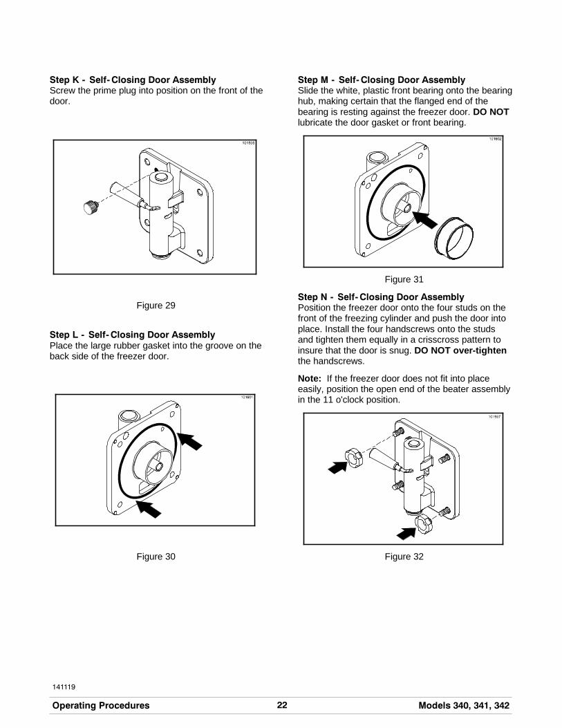
Step K - Self- Closing Door AssemblyScrew the prime plug into position on the front of thedoor.
Figure 29
Step L - Self- Closing Door AssemblyPlace the large rubber gasket into the groove on theback side of the freezer door.
Figure 30
Step M - Self- Closing Door AssemblySlide the white, plastic front bearing onto the bearinghub, making certain that the flanged end of thebearing is resting against the freezer door. DO NOTlubricate the door gasket or front bearing.
Figure 31
Step N - Self- Closing Door AssemblyPosition the freezer door onto the four studs on thefront of the freezing cylinder and push the door intoplace. Install the four handscrews onto the studsand tighten them equally in a crisscross pattern toinsure that the door is snug. DO NOT over-tightenthe handscrews.
Note: If the freezer door does not fit into placeeasily, position the open end of the beater assemblyin the 11 o'clock position.
Figure 32

23Models 340, 341, 342 Operating Procedures
141119
Step O - Self- Closing Door AssemblyPosition the torque arm by inserting it down into thehole on the torque rotor which protrudes from thedoor. Verify proper installation by moving the torquerotor back and forth to be sure it moves freely.
Figure 33
Step P - Self- Closing Door AssemblySlide the long drip pan into the hole in the frontpanel.
Figure 34
Proceed to Step 19.
Step 19Install the front drip tray and splash shield under thedoor spout.
Figure 35
Step 20Lay the hopper gasket and feed tube in the bottom ofthe mix hopper.
Figure 36

24 Models 340, 341, 342Operating Procedures
120619
Step 21(Optional Rack Assembly)
Complete the assembly by inserting the flavor bottlesinto the rack assembly on the front of the machine.
Figure 37
Sanitizing
Step 1Prepare a 2- 1/2 gallon (9.5 liter) pail ofcleaning/sanitizing solution with an active chlorineconcentrate of 100 - 200 PPM (parts per million).USE WARM WATER AND FOLLOW THEMANUFACTURER’S SPECIFICATIONS.
Step 2Pour the sanitizing solution into the hopper and allowit to flow into the freezing cylinder.
Figure 38
Step 3While the solution is flowing into the freezing cylinder,brush clean themix hopper, mix inlet hole, air tube andmix level sensing probe.
Figure 39
Step 4Place the control switch in the “WASH” position. Thiswill cause the sanitizing solution in the freezingcylinder to agitate. Allow the solution to agitate for fiveminutes.
Figure 40
25Models 340, 341, 342 Operating Procedures
150629
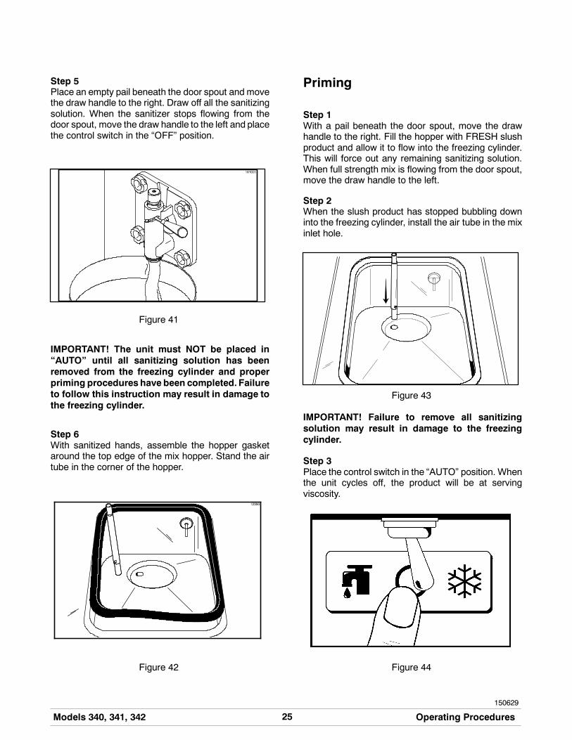
Step 5Place an empty pail beneath the door spout and movethe draw handle to the right. Draw off all the sanitizingsolution. When the sanitizer stops flowing from thedoor spout, move the draw handle to the left and placethe control switch in the “OFF” position.
Figure 41
IMPORTANT! The unit must NOT be placed in“AUTO” until all sanitizing solution has beenremoved from the freezing cylinder and properpriming procedures have been completed. Failureto follow this instruction may result in damage tothe freezing cylinder.
Step 6With sanitized hands, assemble the hopper gasketaround the top edge of the mix hopper. Stand the airtube in the corner of the hopper.
Figure 42
Priming
Step 1With a pail beneath the door spout, move the drawhandle to the right. Fill the hopper with FRESH slushproduct and allow it to flow into the freezing cylinder.This will force out any remaining sanitizing solution.When full strength mix is flowing from the door spout,move the draw handle to the left.
Step 2When the slush product has stopped bubbling downinto the freezing cylinder, install the air tube in the mixinlet hole.
Figure 43
IMPORTANT! Failure to remove all sanitizingsolution may result in damage to the freezingcylinder.
Step 3Place the control switch in the “AUTO” position. Whenthe unit cycles off, the product will be at servingviscosity.
Figure 44

26 Models 340, 341, 342Operating Procedures
150126
Step 4Model 342 Self- Closing Door Only: Loosen theprime plug. When product starts to leak from the bleedport, tighten the prime plug. Allow the product tocontinue filling the mix hopper until the upper mix levelprobe is satisfied and the fill system shuts off.
Figure 45
Step 5Place the hopper cover into position.
Figure 46
Step 6(Optional Flavor Rack Assembly)
To make a refreshing slush product, add the desiredflavor to the bottom of the cup by pressing the pumphandle of the flavor bottle. Move the drawhandle to theright and fill the cup, mixing the flavor with the productbeing drawn.
Figure 47
Closing Procedure
To disassemble the Models 340, 341, and 342, thefollowing items will be needed:
S Two cleaning pailsS Sanitized stainless steel rerun can with lidS Necessary brushes (provided with the
freezer)S CleanerS Single service towels

27Models 340, 341, 342 Operating Procedures
140721
Draining Product From theFreezing Cylinder
Step 1Place the control switch in the “OFF” position as farahead of cleaning time as possible to allow frozenproduct to soften for easier cleaning.
Figure 48
Step 2Remove the hopper cover, gasket, and air tube andtake these parts to the sink for cleaning.
Figure 49
Step 3If local health codes permit the use of rerun, placea sanitized, NSF approved stainless steel reruncontainer under the door spout. Place the controlswitch in the “WASH” position and move the drawhandle to the right. When all the product stops flowingfrom the door spout, move the draw handle to the leftand place the control switch in the “OFF” position.Place a sanitized lid on the rerun container and placeit in the walk- in cooler.(Note: For additional information regarding the properuse of rerun, see item 7 on page 30.)
Note: If local health codesDONOTpermit theuseof rerun, the productmust bediscarded. Follow theinstructions in the previous step, except drain theproduct into a pail and properly discard the mix.
ALWAYS FOLLOW LOCAL HEALTH CODES.
Rinsing
Step 1Pour two gallons (7.6 liters) of cool, clean water intothe mix hopper. With the brushes provided, scrub themix hopper, mix inlet hole, and mix level sensingprobe.
Figure 50
Step 2With a pail beneath the door spout, place the controlswitch in the “WASH” position and move the drawhandle to the right. Drain all the rinse water from thefreezing cylinder. When the rinse water stops flowingfrom the door spout, move the draw handle to the leftand place the control switch in the “OFF” position.
Repeat this procedure until the rinse water beingdrawn from the freezing cylinder is clear.

28 Models 340, 341, 342Operating Procedures
150126
Cleaning
Step 1Prepare a 2- 1/2 gallon (9.5 liter) pail ofcleaning/sanitizing solution with an active chlorineconcentrate of 100 - 200 PPM (parts per million).USE WARM WATER AND FOLLOW THEMANUFACTURER’S SPECIFICATIONS.
Step 2Pour the cleaning solution into the hopper and allow itto flow into the freezing cylinder.
Figure 51
Step 3While the solution is flowing into the freezing cylinder,brush clean the mix hopper and the mix inlet hole.
Figure 52
Step 4Place the control switch in the “WASH” position. Thiswill cause the cleaning solution in the freezing cylinderto agitate.
Figure 53
Step 5Place an empty pail beneath the door spout and movethe draw handle to the right. Draw off all of the cleaningsolution.When the solution stops flowing from thedoorspout, move the draw handle to the left and place thecontrol switch in the “OFF” position.
Figure 54
29Models 340, 341, 342 Operating Procedures
141120
Disassembly
MAKESURECONTROLSWITCH IS INTHE“OFF” POSITION. Failure to do so may cause injuryfrom electrocution or hazardous moving parts .
Step 1Remove the torque arm, handscrews, freezer door,torque rotor, beater assembly, scraper blades, and thedrive shaft from the freezing cylinder. Take these partsto the sink for cleaning.
Step 2Remove the front drip tray and splash shield and takethem to the sink for cleaning.
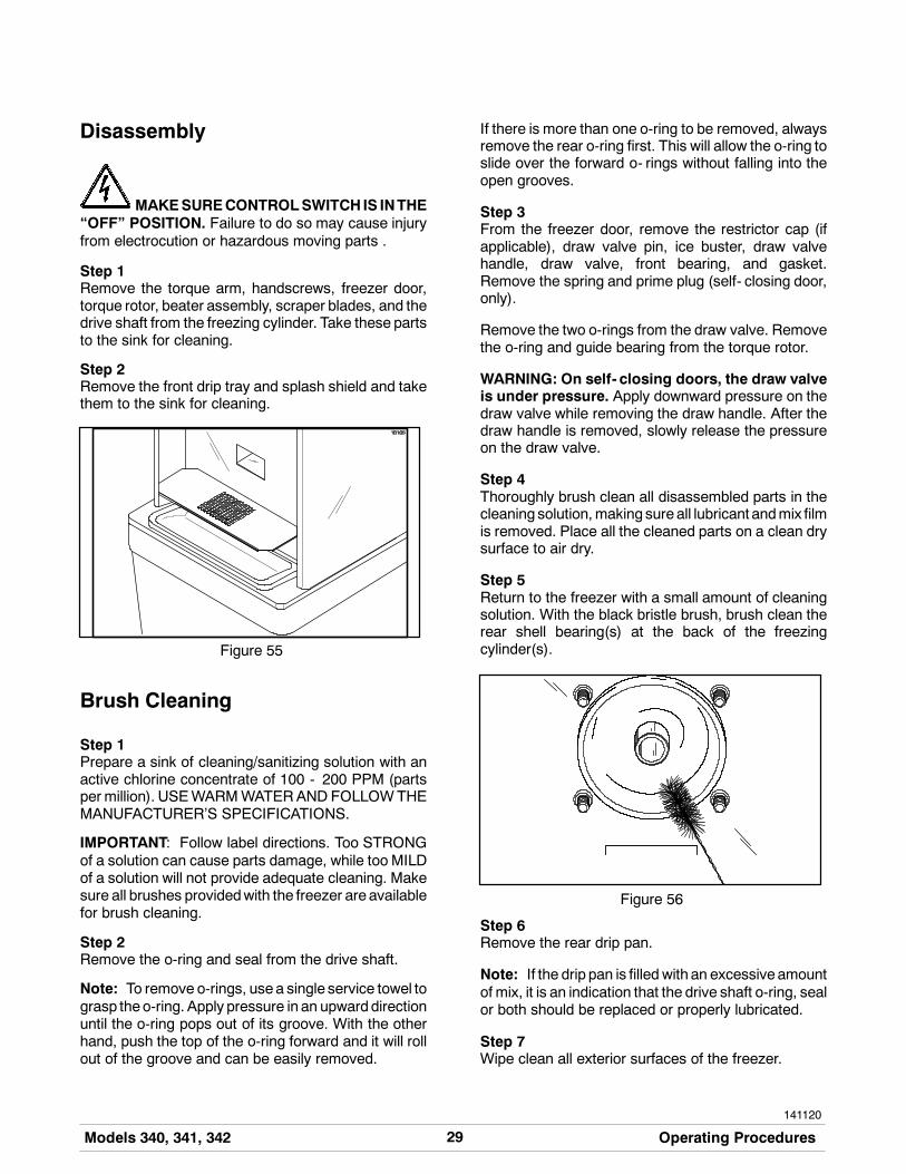
Figure 55
Brush Cleaning
Step 1Prepare a sink of cleaning/sanitizing solution with anactive chlorine concentrate of 100 - 200 PPM (partsper million). USEWARMWATERAND FOLLOWTHEMANUFACTURER’S SPECIFICATIONS.
IMPORTANT: Follow label directions. Too STRONGof a solution can cause parts damage, while too MILDof a solution will not provide adequate cleaning. Makesure all brushes providedwith the freezer are availablefor brush cleaning.
Step 2Remove the o-ring and seal from the drive shaft.
Note: To remove o-rings, usea single service towel tograsp theo-ring. Apply pressure in an upwarddirectionuntil the o-ring pops out of its groove. With the otherhand, push the top of the o-ring forward and it will rollout of the groove and can be easily removed.
If there is more than one o-ring to be removed, alwaysremove the rear o-ring first. This will allow the o-ring toslide over the forward o- rings without falling into theopen grooves.
Step 3From the freezer door, remove the restrictor cap (ifapplicable), draw valve pin, ice buster, draw valvehandle, draw valve, front bearing, and gasket.Remove the spring and prime plug (self- closing door,only).
Remove the two o-rings from the draw valve. Removethe o-ring and guide bearing from the torque rotor.
WARNING: On self- closing doors, the draw valveis under pressure. Apply downward pressure on thedraw valve while removing the draw handle. After thedraw handle is removed, slowly release the pressureon the draw valve.
Step 4Thoroughly brush clean all disassembled parts in thecleaning solution,making sure all lubricant andmix filmis removed. Place all the cleaned parts on a clean drysurface to air dry.
Step 5Return to the freezer with a small amount of cleaningsolution. With the black bristle brush, brush clean therear shell bearing(s) at the back of the freezingcylinder(s).
Figure 56
Step 6Remove the rear drip pan.
Note: If the drip pan is filled with an excessive amountof mix, it is an indication that the drive shaft o-ring, sealor both should be replaced or properly lubricated.
Step 7Wipe clean all exterior surfaces of the freezer.

30 Models 340, 341, 342Important: Operator Checklist
110620
Section 7 Important: Operator Checklist
During Cleaning and Sanitizing
ALWAYS FOLLOW LOCAL HEALTH CODES.
Cleaning and sanitizing schedules are governed byyour State or local regulatory agencies and must befollowed accordingly. The following check pointsshould be stressed during the cleaning and sanitizingoperations.
WE RECOMMEND DAILY CLEANING ANDSANITIZING.
Troubleshooting Bacterial Count
j 1. Thoroughly clean and sanitize the machineregularly, including complete disassembly andbrush cleaning.
j 2. Use all brushes supplied for thorough cleaning.The brushes are specially designed to reach allmix passageways.
j 3. Use the white bristle brush to clean the mix inlethole which extends from the mix hopper downto the rear of the freezing cylinder.
j 4. Use the black bristle brush to thoroughly cleanthe rear shell bearing located at the rear of thefreezing cylinder. Be sure to have a generousamount of cleaning solution on the brush.
j 5. Properly prepare the cleaning and sanitizingsolutions. Read and follow label directionscarefully. Too strong of a solution may damagethe parts and too weak of a solution will not doan adequate job of cleaning or sanitizing.
j 6. Using a screwdriver and cloth towel, keep thefemale square drive socket and rear shellbearing clean and free of lubricant and mixdeposits.
j 7. IF LOCAL HEALTH CODES PERMIT THEUSE OF RERUN, make sure the mix rerun isstored in a sanitized, covered, NSF approvedstainless steel rerun container and used thefollowing day. DO NOT prime the machine with
rerun. When using rerun, skim off the foam anddiscard; then mix the rerun with fresh mix in aratio of 50/50 during the day’s operation.
Regular Maintenance Checks
j 1. Rotate scraper blades to allow both sides of theknife edge to wear evenly. This will contribute toself-sharpening and help maintain fast, efficientfreezing.
j 2. Replace scraper blades that are nicked ordamaged.
j 3. Before installing the beater, be certain that thescraper blades are properly attached over thebeater pins.
j 4. Dispose of o-rings and seals if they are worn,torn, or fit too loosely, and replace them withnew ones.
j 5. Follow all lubricating procedures as outlined in“Assembly”.
j 6. Check the rear shell bearing for signs of wear(excessive mix leakage in rear drip pan) and becertain it is properly cleaned.
j 7. Check the condenser(s) for accumulation of dirtand lint. Dirty condensers will reduce theefficiency and capacity of the machine.Condensers should be cleanedmonthly with asoft brush. Never use screwdrivers or othermetal probes to clean between the fins.Note: For machines equipped with an air filter,it will be necessary to vacuum clean the filterson a monthly schedule.
Caution: Always disconnectelectrical power prior to cleaning thecondenser. Failure to follow this instructionmay result in electrocution.
j 8. On water cooled units, check the water lines forkinks or leaks. Kinks can occur when themachine is moved back and forth for cleaningormaintenance purposes. Deteriorated orcracked water lines should be replaced only byan authorized Taylor mechanic.

31Models 340, 341, 342 Important: Operator Checklist
080213
Winter Storage
If the placeof business is to be closedduring thewintermonths, it is important to protect the freezer byfollowing certain precautions, particularly if thebuilding is subject to freezing conditions.
Disconnect the freezer from the main power source toprevent possible electrical damage.
On water cooled freezers, disconnect the watersupply. Relieve pressure on the spring in the watervalve. Use air pressure on the outlet side to blow outany water remaining in the condenser. This isextremely important. Failure to follow this proceduremay cause severe and costly damage to therefrigeration system.
Your local Taylor Distributor can perform this servicefor you.
Wrap detachable parts of the freezer such as beater,blades, drive shaft, and freezer door, and place in aprotected dry place. Rubber trim parts and gasketscan be protected by wrapping them withmoisture-proof paper. All parts should be thoroughlycleaned of dried mix or lubrication which attract miceand other vermin.

32 Models 340, 341, 342Troubleshooting Guide
Section 8 Troubleshooting Guide
PROBLEM PROBABLE CAUSE REMEDY PAGEREF.
1. No product is beingdispensed with the drawvalve opened.
a. Improper mixing ofproduct.
a. Carefully follow thedirections for mixing theproduct.
- -
b. There is a mix lowcondition.
b. Add mix to the mixhopper.
14
c. The torque arm is notinstalled.
c. Install the torque arm.
d. The torque rotor is bent orimproperly installed.
d. Replace the bent rotor orfollow the assemblyprocedures.
16
2. The product is too thin. a. Improper mixing ofproduct.
a. Carefully follow thedirections for mixingproduct.
- -
b. Scraper blades aremissing or incorrectlyinstalled.
b. Replace or install thescraper blades correctly.
16
c. The consistency controlknob needs adjusting.
c. Adjust accordingly. 14
d. The torque rotor bound,leaving the torque arm inthe “COLD” position.Therefore, the compressorwill not run. (Far Right)
d. Free the torque rotor. - -
3. The product is too stiff. a. The torque rotor bound,leaving the torque arm inthe “WARM” position.Therefore, the compressorcontinually runs. (Far Left)
a. Free the torque rotor. - -
b. The torque arm is bent oris missing.
b. Install or replace thetorque arm.
19
c. The consistency controlknob needs adjusting.
c. Adjust accordingly. 14
d. Improper mixing ofproduct.
d. Carefully follow thedirections for mixingproduct.
- -
e. There is insufficientproduct in the freezingcylinder.
e. Keep the hopper full ofmix.
14

33Models 340, 341, 342 Troubleshooting Guide
150622
PROBLEM PROBABLE CAUSE REMEDY PAGEREF.
4. The freezing cylinder wallsare scored.
a. Scraper blades and/orblade clips are damaged.
a. Replace scraper bladesand/or clips.
16
b. Missing or worn frontbearing on freezer door.
b. Install or replace the frontbearing.
16
c. Unit was placed in AUTObefore all sanitizingsolution was removedfrom freezing cylinder.
c. Place unit in AUTO onlyafter priming is completeand all sanitizing solutionhas been removed.
41
d. The beater assembly isbent/damaged.
d. Call a service technicianto repair or replace.
- - -
5. Unable to remove thedrive shaft.
a. There is lubrication on thesquare end of the driveshaft.
a. Do not lubricate thesquare end. Contactservice technician forremoval.
15
b. The corners of the driveshaft and/or drive couplingare bent.
b. Replace the drive shaftand/or drive coupling.
- -
6. There is excessive mixleakage in the rear drippan.
a. There is improper orinadequate lubrication onthe drive shaft o-ring orseal.
a. Use an approved foodgrade lubricant (example:Taylor Lube) and followthe lubrication procedures.
15
b. Bad or missing o-ring orseal on drive shaft.
b. Replace every 3 months. 15 / 35
c. The rear shell bearing isworn.
c. Contact service technicianfor replacement.
- -
7. There is no freezeroperation with the unit inthe “AUTO” position.
a. The unit is unplugged. a. Plug cord in wallreceptacle.
- -
b. The beater motor hastripped.
b. Place the power switch inthe “OFF” position. Allowthe motor to cool and thenresume normal operation.Contact service technicianif the problem continues.
- -
c. The circuit breaker istripped or the fuse isblown.
c. Reset the circuit breakeror replace the blown fuse.
- -

34 Models 340, 341, 342Troubleshooting Guide
PROBLEM PROBABLE CAUSE REMEDY PAGEREF.
8. The unit is not freezingproduct when in the“AUTO” position.
a. The torque rotor bound,leaving the torque arm inthe “COLD” position.Therefore, the compressorwill not run. (Far Right)
a. Free the torque rotor. - -
b. The torque arm is bent. b. Replace the torque arm. 19
c. The condensers are dirty. c. Clean the condensersregularly.
30
9. The guide bearing ismissing.
a. The guide bearing is stuckin the drive shaft.
a. Remove the guide bearingfrom the hole in the driveshaft.
- -
10. There is excessiveleakage from the doorspout.
a. There is improper orinadequate lubrication onthe draw valve o-rings.
a. Use an approved foodgrade lubricant (example:Taylor Lube) and followthe lubrication procedures.
17
b. The draw valve o-ring isbad or missing.
b. Replace o-rings everythree months.
35
11. The door will not go intoposition easily.
a. The beater assembly isincorrectly positioned.
a. The open end of thebeater assembly shouldbe in the 11 o’clockposition.
18

35Models 340, 341, 342 Parts Replacement Schedule
Section 9 Parts Replacement Schedule
PART DESCRIPTION EVERY 3MONTHS
EVERY 6MONTHS
ANNUALLY QTY.
Drive Shaft O-Ring X 1*
Drive Shaft Seal X 1*
Scraper Blade Inspect & Replaceif Necessary
Minimum 2*
Torque Rotor O-Ring X 1*
Guide Bearing X 1*
Freezer Door Gasket X 1*
Front Bearing X 1*
Draw Valve O-Ring X 2*
Black Bristle Brush, 1” x 2” Inspect & Replaceif Necessary
Minimum 1
Double Ended Brush Inspect & Replaceif Necessary
Minimum 1
White Bristle Brush, 1” x 2” Inspect & Replaceif Necessary
Minimum 1
White Bristle Brush, 3” x 7” Inspect & Replaceif Necessary
Minimum 1
*Double quantity for the Model 342.

36 Models 340, 341, 342Limited Warranty on Equipment
131112
Section 10 Limited Warranty on Equipment
TAYLOR COMPANY LIMITED WARRANTY ON FREEZERS
Taylor Company, a division of Carrier Commercial Refrigeration, Inc. (“Taylor”) is pleased to provide this limitedwarranty on new Taylor-branded freezer equipment available from Taylor to the market generally (the “Product”)to the original purchaser only.
LIMITED WARRANTY
Taylor warrants the Product against failure due to defect in materials or workmanship under normal use andservice as follows. All warranty periods begin on the date of original Product installation. If a part fails due todefect during the applicable warranty period, Taylor, through an authorized Taylor distributor or service agency,will provide a new or re- manufactured part, at Taylor’s option, to replace the failed defective part at no charge forthe part. Except as otherwise stated herein, these are Taylor’s exclusive obligations under this limited warranty fora Product failure. This limited warranty is subject to all provisions, conditions, limitations and exclusions listedbelow and on the reverse (if any) of this document.
Product Part Limited Warranty Period
Soft ServeFrozen YogurtShakesSmoothies
Frozen BeverageBatch Desserts
Insulated shell assembly Five (5) years
Refrigeration compressor(except service valve)
Five (5) years
Beater motors Two (2) years
Beater drive gear Two (2) years
Printed circuit boards andSoftech controls beginningwith serial number H8024200
Two (2) years
Parts not otherwise listed inthis table or excluded below
One (1) year
LIMITED WARRANTY CONDITIONS
1. If the date of original installation of the Product cannot be verified, then the limited warranty period beginsninety (90) days from the date of Product manufacture (as indicated by the Product serial number). Proof ofpurchase may be required at time of service.
2. This limited warranty is valid only if the Product is installed and all required service work on the Product isperformed by an authorized Taylor distributor or service agency, and only if genuine, new Taylor parts areused.
3. Installation, use, care, and maintenance must be normal and in accordance with all instructions contained inthe Taylor Operator’s Manual.
4. Defective parts must be returned to the authorized Taylor distributor or service agency for credit.
5. The use of any refrigerant other than that specified on the Product’s data label will void this limited warranty.
LIMITED WARRANTY EXCEPTIONS
This limited warranty does not cover:
1. Labor or other costs incurred for diagnosing, repairing, removing, installing, shipping, servicing or handling ofdefective parts, replacement parts, or new Products.
2. Normal maintenance, cleaning and lubrication as outlined in the Taylor Operator’s Manual, including cleaningof condensers.

37Models 340, 341, 342 Limited Warranty on Equipment
131112
3. Replacement of wear items designated as Class “000” parts in the Taylor Operator’s Manual.
4. External hoses, electrical power supplies, and machine grounding.
5. Parts not supplied or designated by Taylor, or damages resulting from their use.
6. Return trips or waiting time required because a service technician is prevented from beginning warrantyservice work promptly upon arrival.
7. Failure, damage or repairs due to faulty installation, misapplication, abuse, no or improper servicing,unauthorized alteration or improper operation or use as indicated in the Taylor Operator’s Manual, includingbut not limited to the failure to use proper assembly and cleaning techniques, tools, or approved cleaningsupplies.
8. Failure, damage or repairs due to theft, vandalism, wind, rain, flood, high water, water, lightning, earthquakeor any other natural disaster, fire, corrosive environments, insect or rodent infestation, or other casualty,accident or condition beyond the reasonable control of Taylor; operation above or below the electrical orwater supply specification of the Product; or components repaired or altered in any way so as, in thejudgment of the Manufacturer, to adversely affect performance, or normal wear or deterioration.
9. Any Product purchased over the Internet.
10. Failure to start due to voltage conditions, blown fuses, open circuit breakers, or damages due to theinadequacy or interruption of electrical service.
11. Electricity or fuel costs, or increases in electricity or fuel costs from any reason whatsoever.
12. Damages resulting from the use of any refrigerant other than that specified on the Product’s data label willvoid this limited warranty.
13. Any cost to replace, refill or dispose of refrigerant, including the cost of refrigerant.
14. ANY SPECIAL, INDIRECT OR CONSEQUENTIAL PROPERTY OR COMMERCIAL DAMAGE OF ANYNATURE WHATSOEVER. Some jurisdictions do not allow the exclusion of incidental or consequentialdamages, so this limitation may not apply to you.
This limited warranty gives you specific legal rights, and you may also have other rights which vary fromjurisdiction to jurisdiction.
LIMITATION OF WARRANTY
THIS LIMITED WARRANTY IS EXCLUSIVE AND IS IN LIEU OF ALL OTHER WARRANTIES, CONDITIONSAND/OR REMEDIES UNDER THE LAW, INCLUDING ANY IMPLIED WARRANTIES OR CONDITIONS OFMERCHANTABILITY OR FITNESS FOR A PARTICULAR PURPOSE. THE ORIGINAL OWNER’S SOLEREMEDY WITH RESPECT TO ANY PRODUCTS SHALL BE REPAIR OR REPLACEMENT OF DEFECTIVECOMPONENTS UNDER THE TERMS OF THIS LIMITED WARRANTY. ALL RIGHTS TO CONSEQUENTIALOR INCIDENTAL DAMAGES (INCLUDING CLAIMS FOR LOST SALES, LOST PROFITS, PRODUCT LOSS,PROPERTY DAMAGES OR SERVICE EXPENSES) ARE EXPRESSLY EXCLUDED. THE EXPRESSWARRANTIES MADE IN THIS LIMITED WARRANTY MAY NOT BE ALTERED, ENLARGED, OR CHANGEDBY ANY DISTRIBUTOR, DEALER, OR OTHER PERSON, WHATSOEVER.
LEGAL REMEDIES
The owner must notify Taylor in writing, by certified or registered letter to the following address, of any defect orcomplaint with the Product, stating the defect or complaint and a specific request for repair, replacement, or othercorrection of the Product under warranty, mailed at least thirty (30) days before pursuing any legal rights orremedies.
Taylor Companya division of Carrier Commercial Refrigeration, Inc.
750 N. Blackhawk Blvd.Rockton, IL 61072, U.S.A.

38 Models 340, 341, 342Limited Warranty on Parts
131112
Section 11 Limited Warranty on Parts
TAYLOR COMPANY LIMITED WARRANTY ON TAYLOR GENUINE PARTS
Taylor Company, a division of Carrier Commercial Refrigeration, Inc. (“Taylor”) is pleased to provide this limitedwarranty on new Taylor genuine replacement components and parts available from Taylor to the market generally(the “Parts”) to the original purchaser only.
LIMITED WARRANTY
Taylor warrants the Parts against failure due to defect in materials or workmanship under normal use and serviceas follows. All warranty periods begin on the date of original installation of the Part in the Taylor unit. If a Part failsdue to defect during the applicable warranty period, Taylor, through an authorized Taylor distributor or serviceagency, will provide a new or re- manufactured Part, at Taylor’s option, to replace the failed defective Part at nocharge for the Part. Except as otherwise stated herein, these are Taylor’s exclusive obligations under this limitedwarranty for a Part failure. This limited warranty is subject to all provisions, conditions, limitations and exclusionslisted below and on the reverse (if any) of this document.
Part’s Warranty Class Code or Part Limited Warranty Period
Class 103 Parts¹ Three (3) months
Class 212 Parts² Twelve (12) months
Class 512 Parts Twelve (12) months
Class 000 Parts No warranty
Taylor Part #072454 (Motor- 24VDC *C832/C842*) Four (4) years
LIMITED WARRANTY CONDITIONS
1. If the date of original installation of the Part cannot be otherwise verified, proof of purchase may be requiredat time of service.
2. This limited warranty is valid only if the Part is installed and all required service work in connection with thePart is performed by an authorized Taylor distributor or service agency.
3. The limited warranty applies only to Parts remaining in use by their original owner at their original installationlocation in the unit of original installation.
4. Installation, use, care, and maintenance must be normal and in accordance with all instructions contained inthe Taylor Operator’s Manual.
5. Defective Parts must be returned to the authorized Taylor distributor or service agency for credit.
6. This warranty is not intended to shorten the length of any warranty coverage provided pursuant to a separateTaylor Limited Warranty on freezer or grill equipment.
7. The use of any refrigerant other than that specified for the unit in which the Part is installed will void thislimited warranty.
1, 2 Except that Taylor Part #032129SER2 (Compressor-Air-230V SERV) and Taylor Part #075506SER1(Compressor-Air-115V 60HZ) shall have a limited warranty period of twelve (12) months when used in Taylorfreezer equipment and a limited warranty period of two (2) years when used in Taylor grill equipment.

39Models 340, 341, 342 Limited Warranty on Parts
131112
LIMITED WARRANTY EXCEPTIONS
This limited warranty does not cover:
1. Labor or other costs incurred for diagnosing, repairing, removing, installing, shipping, servicing or handling ofdefective Parts, replacement Parts, or new Parts.
2. Normal maintenance, cleaning and lubrication as outlined in the Taylor Operator’s Manual, including cleaningof condensers or carbon and grease buildup.
3. Required service, whether cleaning or general repairs, to return the cooking surface assemblies, includingthe upper platen and lower plate, to an operational condition to achieve proper cooking or allow properassembly of release sheets and clips as a result of grease build-up on the cooking surfaces, including butnot limited to the platen and plate, sides of the shroud or top of the shroud.
4. Replacement of cooking surfaces, including the upper platen and lower plate, due to pitting or corrosion (orin the case of the upper platen, due to loss of plating) as a result of damage due to the impact of spatulas orother small wares used during the cooking process or as a result of the use of cleaners, cleaning materialsor cleaning processes not approved for use by Taylor.
5. Replacement of wear items designated as Class “000” Parts in the Taylor Operator’s Manual, as well as anyrelease sheets and clips for the Product’s upper platen assembly.
6. External hoses, electrical power supplies, and machine grounding.
7. Parts not supplied or designated by Taylor, or damages resulting from their use.
8. Return trips or waiting time required because a service technician is prevented from beginning warrantyservice work promptly upon arrival.
9. Failure, damage or repairs due to faulty installation, misapplication, abuse, no or improper servicing,unauthorized alteration or improper operation or use as indicated in the Taylor Operator’s Manual, includingbut not limited to the failure to use proper assembly and cleaning techniques, tools, or approved cleaningsupplies.
10. Failure, damage or repairs due to theft, vandalism, wind, rain, flood, high water, water, lightning, earthquakeor any other natural disaster, fire, corrosive environments, insect or rodent infestation, or other casualty,accident or condition beyond the reasonable control of Taylor; operation above or below the gas, electrical orwater supply specification of the unit in which a part is installed; or Parts or the units in which they areinstalled repaired or altered in any way so as, in the judgment of Taylor, to adversely affect performance, ornormal wear or deterioration.
11. Any Part purchased over the Internet.
12. Failure to start due to voltage conditions, blown fuses, open circuit breakers, or damages due to theinadequacy or interruption of electrical service.
13. Electricity, gas or other fuel costs, or increases in electricity or fuel costs from any reason whatsoever.
14. Damages resulting from the use of any refrigerant other than that specified for the unit in which the Part isinstalled will void this limited warranty.
15. Any cost to replace, refill or dispose of refrigerant, including the cost of refrigerant.
16. ANY SPECIAL, INDIRECT OR CONSEQUENTIAL PROPERTY OR COMMERCIAL DAMAGE OF ANYNATURE WHATSOEVER. Some jurisdictions do not allow the exclusion of incidental or consequentialdamages, so this limitation may not apply to you.
This limited warranty gives you specific legal rights, and you may also have other rights which vary fromjurisdiction to jurisdiction.

40 Models 340, 341, 342Limited Warranty on Parts
131112
LIMITATION OF WARRANTY
THIS LIMITED WARRANTY IS EXCLUSIVE AND IS IN LIEU OF ALL OTHER WARRANTIES, CONDITIONSAND/OR REMEDIES UNDER THE LAW, INCLUDING ANY IMPLIED WARRANTIES OR CONDITIONS OFMERCHANTABILITY OR FITNESS FOR A PARTICULAR PURPOSE. THE ORIGINAL OWNER’S SOLEREMEDY WITH RESPECT TO ANY PRODUCTS SHALL BE REPAIR OR REPLACEMENT OF DEFECTIVEPARTS UNDER THE TERMS OF THIS LIMITED WARRANTY. ALL RIGHTS TO CONSEQUENTIAL ORINCIDENTAL DAMAGES (INCLUDING CLAIMS FOR LOST SALES, LOST PROFITS, PRODUCT LOSS,PROPERTY DAMAGES OR SERVICE EXPENSES) ARE EXPRESSLY EXCLUDED. THE EXPRESSWARRANTIES MADE IN THIS LIMITED WARRANTY MAY NOT BE ALTERED, ENLARGED, OR CHANGEDBY ANY DISTRIBUTOR, DEALER, OR OTHER PERSON, WHATSOEVER.
LEGAL REMEDIES
The owner must notify Taylor in writing, by certified or registered letter to the following address, of any defect orcomplaint with the Part, stating the defect or complaint and a specific request for repair, replacement, or othercorrection of the Part under warranty, mailed at least thirty (30) days before pursuing any legal rights or remedies.
Taylor Companya division of Carrier Commercial Refrigeration, Inc.
750 N. Blackhawk Blvd.Rockton, IL 61072, U.S.A.