Embed Size (px)
Citation preview
OPERATOR'SMANUAL
Model 750, 751, 754, 774,791, & 794 Soft Serve Freezers
Original Operating Instructions
028754-M2/01/02 (Original Publication)
Updated 8/3/15
Complete this page for quick reference when service is required:
Taylor Distributor:
Address:
Phone:
Service:
Parts:
Date of Installation:
Information found on the data label:
Model Number:
Serial Number:
Electrical Specs: Voltage Cycle
Phase
Maximum Fuse Size: A
Minimum Wire Ampacity: A
E 2002 Carrier Commercial Refrigeration, Inc.028754-MAny unauthorized reproduction, disclosure, or distribution of copies by any person of any portion of this work maybe a violation of Copyright Law of the United States of America and other countries, could result in the awardingof Statutory Damages of up to $250,000 (17 USC 504) for infringement, and may result in further civil and criminalpenalties. All rights reserved.
Taylor Companya division of Carrier Commercial Refrigeration, Inc.750 N. Blackhawk Blvd.Rockton, IL 61072
Table of Contents Models 750, 751, 754, 774, 791, 794
Table of Contents
Section 1 To the Installer 1. . . . . . . . . . . . . . . . . . . . . . . . . . . . . . . . . . . . . . . . . . . .
Section 2 To the Operator 4. . . . . . . . . . . . . . . . . . . . . . . . . . . . . . . . . . . . . . . . . . .
Section 3 Safety 5. . . . . . . . . . . . . . . . . . . . . . . . . . . . . . . . . . . . . . . . . . . . . . . . . . . .
Section 4 Operator Parts Identification 7. . . . . . . . . . . . . . . . . . . . . . . . . . . . . . .Model 750 7. . . . . . . . . . . . . . . . . . . . . . . . . . . . . . . . . . . . . . . . . . . . . . . . . . . . . . . . . . . .Model 751 8. . . . . . . . . . . . . . . . . . . . . . . . . . . . . . . . . . . . . . . . . . . . . . . . . . . . . . . . . . . .Model 754 9. . . . . . . . . . . . . . . . . . . . . . . . . . . . . . . . . . . . . . . . . . . . . . . . . . . . . . . . . . . .Model 774 10. . . . . . . . . . . . . . . . . . . . . . . . . . . . . . . . . . . . . . . . . . . . . . . . . . . . . . . . . . . .Model 774 Topping Pump (053794- ) 11. . . . . . . . . . . . . . . . . . . . . . . . . . . . . . . . . . . .Model 791 12. . . . . . . . . . . . . . . . . . . . . . . . . . . . . . . . . . . . . . . . . . . . . . . . . . . . . . . . . . . .Model 794 13. . . . . . . . . . . . . . . . . . . . . . . . . . . . . . . . . . . . . . . . . . . . . . . . . . . . . . . . . . . .Models 750 & 751 Single Spout Door and Beater Assembly 14. . . . . . . . . . . . . . . .Models 754, 774 & 794 Three Spout Door and Beater Assembly 15. . . . . . . . . . . .Model 791 Three Spout Door and Beater Assembly 16. . . . . . . . . . . . . . . . . . . . . . .Accessories 17. . . . . . . . . . . . . . . . . . . . . . . . . . . . . . . . . . . . . . . . . . . . . . . . . . . . . . . . . .
Section 5 Important: To the Operator 18. . . . . . . . . . . . . . . . . . . . . . . . . . . . . . . . .Symbol Definitions 18. . . . . . . . . . . . . . . . . . . . . . . . . . . . . . . . . . . . . . . . . . . . . . . . . . . .Power Switch 19. . . . . . . . . . . . . . . . . . . . . . . . . . . . . . . . . . . . . . . . . . . . . . . . . . . . . . . . .MIX LOW Indicator Light 19. . . . . . . . . . . . . . . . . . . . . . . . . . . . . . . . . . . . . . . . . . . . . . .MIX REF Key 19. . . . . . . . . . . . . . . . . . . . . . . . . . . . . . . . . . . . . . . . . . . . . . . . . . . . . . . . .STANDBY Key 19. . . . . . . . . . . . . . . . . . . . . . . . . . . . . . . . . . . . . . . . . . . . . . . . . . . . . . . .WASH Key 19. . . . . . . . . . . . . . . . . . . . . . . . . . . . . . . . . . . . . . . . . . . . . . . . . . . . . . . . . . .AUTO Key 19. . . . . . . . . . . . . . . . . . . . . . . . . . . . . . . . . . . . . . . . . . . . . . . . . . . . . . . . . . .Reset Button 20. . . . . . . . . . . . . . . . . . . . . . . . . . . . . . . . . . . . . . . . . . . . . . . . . . . . . . . . .Air Tube 20. . . . . . . . . . . . . . . . . . . . . . . . . . . . . . . . . . . . . . . . . . . . . . . . . . . . . . . . . . . . .Adjustable Draw Handle 20. . . . . . . . . . . . . . . . . . . . . . . . . . . . . . . . . . . . . . . . . . . . . . .
Section 6 Operating Procedures 21. . . . . . . . . . . . . . . . . . . . . . . . . . . . . . . . . . . . .Prior to Set- Up (Model 774) 21. . . . . . . . . . . . . . . . . . . . . . . . . . . . . . . . . . . . . . . . . . . .Assembly 21. . . . . . . . . . . . . . . . . . . . . . . . . . . . . . . . . . . . . . . . . . . . . . . . . . . . . . . . . . . .Sanitizing 26. . . . . . . . . . . . . . . . . . . . . . . . . . . . . . . . . . . . . . . . . . . . . . . . . . . . . . . . . . . .Priming 28. . . . . . . . . . . . . . . . . . . . . . . . . . . . . . . . . . . . . . . . . . . . . . . . . . . . . . . . . . . . . .Closing Procedure 29. . . . . . . . . . . . . . . . . . . . . . . . . . . . . . . . . . . . . . . . . . . . . . . . . . . .
Models 750, 751, 754, 774, 791, 794 Table of Contents
Table of Contents - Page 2
Draining Product From The Freezing Cylinder 29. . . . . . . . . . . . . . . . . . . . . . . . . . . .Rinsing 29. . . . . . . . . . . . . . . . . . . . . . . . . . . . . . . . . . . . . . . . . . . . . . . . . . . . . . . . . . . . . .Cleaning 29. . . . . . . . . . . . . . . . . . . . . . . . . . . . . . . . . . . . . . . . . . . . . . . . . . . . . . . . . . . . .Disassembly 30. . . . . . . . . . . . . . . . . . . . . . . . . . . . . . . . . . . . . . . . . . . . . . . . . . . . . . . . . .Brush Cleaning 30. . . . . . . . . . . . . . . . . . . . . . . . . . . . . . . . . . . . . . . . . . . . . . . . . . . . . . .
Section 7 Important: Operator Checklist 31. . . . . . . . . . . . . . . . . . . . . . . . . . . . . .During Cleaning and Sanitizing 31. . . . . . . . . . . . . . . . . . . . . . . . . . . . . . . . . . . . . . . . .Troubleshooting Bacterial Count 31. . . . . . . . . . . . . . . . . . . . . . . . . . . . . . . . . . . . . . . .Regular Maintenance Checks 31. . . . . . . . . . . . . . . . . . . . . . . . . . . . . . . . . . . . . . . . . . .Winter Storage 32. . . . . . . . . . . . . . . . . . . . . . . . . . . . . . . . . . . . . . . . . . . . . . . . . . . . . . . .
Section 8 Troubleshooting Guide 33. . . . . . . . . . . . . . . . . . . . . . . . . . . . . . . . . . . .
Section 9 Parts Replacement Schedule 36. . . . . . . . . . . . . . . . . . . . . . . . . . . . . . .
Section 10 Limited Warranty on Equipment 37. . . . . . . . . . . . . . . . . . . . . . . . . . . .
Section 11 Limited Warranty on Parts 39. . . . . . . . . . . . . . . . . . . . . . . . . . . . . . . . .
Note: Continuing research results in steady improvements; therefore, informationin this manual is subject to change without notice.
Note: Only instructions originating from the factory or its authorized translationrepresentative(s) are considered to be the original set of instructions.
E 2002 Carrier Commercial Refrigeration, Inc. (Original Publication)(Updated August, 2015)All rights reserved.028754-M
Any unauthorized reproduction, disclosure, or distribution of copies by any person of any portion of this workmay be a violation of Copyright Law of the United States of America and other countries, could result in theawarding of Statutory Damages of up to $250,000 (17 USC 504) for infringement, and may result in furthercivil and criminal penalties. All rights reserved.
Taylor Companya division of Carrier Commercial Refrigeration, Inc.750 N. Blackhawk Blvd.Rockton, IL 61072
1Models 750, 751, 754, 774, 791, 794 To the Installer
131206
Section 1 To the Installer
The following information has been included in themanual as safety and regulatory guidelines. Forcomplete installation instructions, please see theInstallation Checklist.
Installer Safety
In all areas of the world, equipment should beinstalled in accordance with existing local codes.Please contact your local authorities if you have anyquestions.
Care should be taken to ensure that all basic safetypractices are followed during the installation andservicing activities related to the installation andservice of Taylor equipment.
S Only authorized Taylor service personnelshould perform installation and repairs on theequipment.
S Authorized service personnel should consultOSHA Standard 29CFRI910.147 or theapplicable code of the local area for theindustry standards on lockout/tagoutprocedures before beginning any installationor repairs.
S Authorized service personnel must ensurethat the proper PPE is available and wornwhen required during installation and service.
S Authorized service personnelmust remove allmetal jewelry, rings, and watches beforeworking on electrical equipment.
The main power supply(ies) to the freezermust be disconnected prior to performing any repairs.Failure to follow this instruction may result in personalinjury or death from electrical shock or hazardousmoving parts as well as poor performance or damageto the equipment.
Note: All repairs must be performed by anauthorized Taylor Service Technician.
This unit has many sharp edges that cancause severe injuries.
Site Preparation
Review the area the unit is to be installed in beforeuncrating the unit making sure that all possiblehazards the user or equipment may come into havebeen addressed.
Air Cooled Units
DO NOT obstruct air intake and discharge openings:
Counter Model: 6” (152 mm) minimum air space onboth sides and 0” on the rear.Console Models: 3” (76 mm) minimum air space onall sides.
This will allow for adequate air flow across thecondenser(s). Failure to allowadequate clearance canreduce the refrigeration capacity of the freezer andpossibly causepermanent damage to the compressor.
For Indoor UseOnly: This unit is designed to operateindoors, under normal ambient temperatures of70_-75_F (21_-24_C). The freezer has successfullyperformed in high ambient temperatures of104_(40_C) at reduced capacities.
This unit must NOT be installed in an areawhere a water jet or hose can be used. NEVER use awater jet or hose to rinse or clean the unit. Failure tofollow this instruction may result in electrocution.
This unit must be installed on a level surfaceto avoid the hazard of tipping. Extreme care should betaken in moving this equipment for any reason. Two ormore persons are required to safely move this unit.Failure to comply may result in personal injury orequipment damage.
Uncrate the unit and inspect it for damage. Report anydamage to your Taylor Distributor.
This piece of equipment is made in the USA and hasUSA sizes of hardware. All metric conversions areapproximate and vary in size.

2 Models 750, 751, 754, 774, 791, 794To the Installer
101027
Water Connections(Water Cooled Units Only)
An adequate cold water supply must be provided witha hand shut- off valve. On the underside rear of thebase pan, two 3/8” I.P.S. (for single- head units) or two1/2” I.P.S. (for double- head units) water connectionsfor inlet and outlet have been provided for easyhook- up. 1/2” inside diameter water lines should beconnected to the machine. (Flexible lines arerecommended, if local codes permit.) Depending onlocal water conditions, it may be advisable to install awater strainer to prevent foreign substances fromclogging the automatic water valve. There will be onlyone water “in” and one water “out” connection for bothsingle- head and double- head units. DO NOT install ahand shut- off valve on the water “out” line! Watershould always flow in this order: first, through theautomatic water valve; second, through thecondenser; and third, through the outlet fitting to anopen trap drain.
A back flow prevention device is requiredon the incoming water connection side. Pleaserefer to the applicable National, State, and local codesfor determining the proper configuration.
Electrical Connections
In the United States, this equipment is intended to beinstalled in accordance with the National ElectricalCode (NEC), ANSI/NFPA70-1987. Thepurpose of theNEC code is the practical safeguardingof persons andproperty from hazards arising from the use ofelectricity. This code contains provisions considerednecessary for safety. In all other areas of the world,equipment should be installed in accordance with theexisting local codes. Please contact your localauthorities.
FOLLOW YOUR LOCAL ELECTRICAL CODES!
Each unit requires one power supply for each datalabel on the unit. Check the data label(s) on the freezerfor branch circuit overcurrent protection or fuse, circuitampacity, and other electrical specifications. Refer tothe wiring diagram provided inside of the electrical boxfor proper power connections.
CAUTION: THIS EQUIPMENT MUST BEPROPERLY GROUNDED! FAILURE TO DO SOCAN RESULT IN SEVERE PERSONAL INJURYFROM ELECTRICAL SHOCK!
DONOT operate this freezer with larger fusesthan specified on the unit data label. Failure to followthis instruction may result in electrocution or damageto the machine.
This unit is provided with an equipotentialgrounding lug that is to be properly attached to the rearof the frameby the authorized installer. The installationlocation is marked by the equipotential bondingsymbol (5021 of IEC 60417-1) on both the removablepanel and the equipment’s frame.
Stationary appliances which are not equippedwith a power cord and a plug or another device todisconnect the appliance from the power source musthave an all-pole disconnecting device with a contactgap of at least 3 mm installed in the externalinstallation.
Appliances that are permanently connected tofixed wiring and for which leakage currents mayexceed 10 mA, particularly when disconnected or notused for long periods, or during initial installation, shallhave protective devices such as a GFI, to protectagainst the leakage of current, installed by theauthorized personnel to the local codes.
3Models 750, 751, 754, 774, 791, 794 To the Installer
130819
Supply cords used with this unit shall beoil-resistant, sheathed flexible cable not lighter thanordinary polychloroprene or other equivalent syntheticelastomer-sheathed cord (Code designation 60245IEC 57) installed with the proper cord anchorage torelieve conductors from strain, including twisting, atthe terminals and protect the insulation of theconductors from abrasion.
If the supply cord is damaged, it must be replaced byan authorized Taylor service technician in order toavoid a hazard.
Beater Rotation
Beater rotation must be clockwise as viewedlooking into the freezing cylinder.
Note: The following procedures should beperformed by a trained service technician.
To correct the rotation on a three- phase unit,interchange any two incoming power supply lines atfreezer main terminal block only.
To correct rotation on a single- phase unit, change theleads inside the beater motor. (Follow the diagramprinted on the motor.)
Electrical connections are made directly to theterminal block provided in themain control box locatedunder the upper left side panel on the countertop unit,or behind the service panel on the console units.
Refrigerant
In consideration of our environment, Tayloruses only earth friendly HFC refrigerants. The HFCrefrigerant used in this unit is R404A. This refrigerantis generally considered non-toxic and non-flammable,with an Ozone Depleting Potential (ODP) of zero (0).
However, any gas under pressure is potentiallyhazardous andmust be handled with caution. NEVERfill any refrigerant cylinder completely with liquid.Filling the cylinder to approximately 80% will allow fornormal expansion.
Use only R404A refrigerant that conforms tothe AHRI standard 700 specification. The use of anyother refrigerant may expose users and operators tounexpected safety hazards.
Refrigerant liquid sprayed onto the skin maycause serious damage to tissue. Keep eyes and skinprotected. If refrigerant burns should occur, flushimmediately with cold water. If burns are severe, applyice packs and contact a physician immediately.
Taylor reminds technicians to be cautious ofgovernment laws regarding refrigerant recovery,recycling, and reclaiming systems. If you have anyquestions regarding these laws, please contact thefactory Service Department.
WARNING: R404A refrigerant used inconjunction with polyolester oils is extremely moistureabsorbent. When opening a refrigeration system, themaximum time the system is openmust not exceed 15minutes. Cap all open tubing to prevent humid air orwater from being absorbed by the oil.

4 Models 750, 751, 754, 774, 791, 794To the Operator
131206
Section 2 To the Operator
The freezer you have purchased has been carefullyengineered andmanufactured to give you dependableoperation. The Taylor soft- serve models covered inthis manual consist of the following: 750, 751, 754,774, 791, and 794.
Theseunits, whenproperly operatedand cared for, willproduce a consistent quality product. Like allmechanical products, they will require cleaning andmaintenance. A minimum amount of care andattention is necessary if the operating proceduresoutlined in this manual are followed closely.
This Operator’s Manual should be readbefore operating or performing any maintenance onyour equipment.
Your freezer will NOT eventually compensate andcorrect for any errors during the set- up or fillingoperations. Thus, the initial assembly and primingprocedures are of extreme importance. It is stronglyrecommended that all personnel responsible for theequipment’s operation study these procedurestogether in order to be properly trained and to makesure that no misunderstandings exist.
In the event you should require technical assistance,please contact your local authorized TaylorDistributor.
Note: Your Taylor warranty is valid only if the parts areauthorized Taylor parts, purchased from the localauthorized Taylor Distributor, and only if all requiredservice work is provided by an authorized Taylorservice technician. Taylor reserves the right to denywarranty claims on units or parts if non- Taylorapproved parts or incorrect refrigerant were installedin the unit, system modifications were performedbeyond factory recommendations, or it is determinedthat the failure was caused by abuse, misuse, neglect,or failure to follow all operating instructions. For fulldetails of your Taylor Warranty, please see the LimitedWarranty section in this manual.
Note: Constant research results in steadyimprovements; therefore, information in thismanual is subject to change without notice.
If the crossed out wheeled bin symbol isaffixed to this product, it signifies that this product is
compliant with the EUDirective as well as other similarlegislation in effect after August 13, 2005. Therefore,it must be collected separately after its use iscompleted, and cannot be disposed as unsortedmunicipal waste. The user is responsible for returningthe product to the appropriate collection facility, asspecified by your local code.
For additional information regarding applicable locallaws, please contact the municipal facility and/or localdistributor.
Compressor Warranty Disclaimer
The refrigeration compressor(s) on this unit arewarranted for the term stated in the Limited Warrantysection in this manual. However, due to the MontrealProtocol and the U.S. Clean Air Act Amendments of1990, many new refrigerants are being tested anddeveloped, thus seeking their way into the serviceindustry. Some of these new refrigerants are beingadvertised as drop- in replacements for numerousapplications. It should be noted that in the event ofordinary service to this unit’s refrigeration system,only the refrigerant specified on the affixed datalabel should be used. The unauthorized use ofalternate refrigerants will void your Taylor compressorwarranty. It is the unit owner’s responsibility to makethis fact known to any technician he employs.
It should also be noted that Taylor does not warrant therefrigerant used in its equipment. For example, if therefrigerant is lost during the course of ordinary serviceto this machine, Taylor has no obligation to eithersupply or provide its replacement either at billable orunbillable terms. Taylor does have the obligation torecommend a suitable replacement if the originalrefrigerant is banned, obsoleted, or no longer availableduring the five year warranty of the compressor.
The Taylor Company will continue to monitor theindustry and test new alternates as they are beingdeveloped. Should a new alternate prove, through ourtesting, that it would be accepted as a drop- inreplacement, then the above disclaimer wouldbecome null and void. To find out the current status ofan alternate refrigerant as it relates to yourcompressor warranty, call the local Taylor Distributoror the Taylor Factory. Be prepared to provide theModel/Serial Number of the unit in question.
5Models 750, 751, 754, 774, 791, 794 Safety
130819
Section 3 Safety
We, at Taylor Company, are concerned about thesafety of the operatorwhen heor she comes in contactwith the freezer and its parts. Taylor has gone toextreme efforts to design and manufacture built- insafety features to protect both you and the servicetechnician. As an example, warning labels have beenattached to the freezer to further point out safetyprecautions to the operator.
IMPORTANT - Failure to adhere to thefollowing safety precautions may result in severepersonal injury or death. Failure to comply withthese warnings may damage the machine and itscomponents. Component damage will result inpart replacement expense and service repairexpense.
DONOT operate the freezer without readingthis Operator Manual. Failure to follow this instructionmay result in equipment damage, poor freezerperformance, health hazards, or personal injury.
This appliance is to be used only by trainedpersonnel. It is not intended for use by children orpeople with reduced physical, sensory, or mentalcapabilities, or lack of experience and knowledge,unless given supervision or instruction concerning theuse of the appliance by a person responsible for theirsafety.
This unit is provided with an equipotentialgrounding lug that is to be properly attached to the rearof the frameby the authorized installer. The installationlocation is marked by the equipotential bondingsymbol (5021 of IEC 60417-1) on both the removablepanel and the equipment’s frame.
DO NOT use a water jet to clean or rinse thefreezer. Failure to follow these instructions may resultin serious electrical shock.
S DO NOT operate the freezer unless it isproperly grounded.
S DO NOT operate the freezer with larger fusesthan specified on the freezer data label.
S All repairs must be performed by anauthorized Taylor service technician.
S Themain power supplies to the machinemustbe disconnected prior to performing anyrepairs.
S CordConnectedUnits: Only Taylor authorizedservice technicians may install a plug on thisunit.
S Stationary appliances which are not equippedwith a power cord anda plugor another deviceto disconnect the appliance from the powersource must have an all-pole disconnectingdevice with a contact gap of at least 3 mminstalled in the external installation.
S Appliances that are permanently connected tofixed wiring and for which leakage currentsmay exceed 10 mA, particularly whendisconnected or not used for long periods, orduring initial installation, shall have protectivedevices such as a GFI, to protect against theleakage of current, installed by the authorizedpersonnel to the local codes.
S Supply cords used with this unit shall beoil-resistant, sheathed flexible cable notlighter than ordinary polychloroprene or otherequivalent synthetic elastomer-sheathed cord(Code designation 60245 IEC 57) installedwith the proper cord anchorage to relieveconductors from strain, including twisting, atthe terminals and protect the insulation of theconductors from abrasion.
If the supply cord is damaged, it must bereplaced by an authorized Taylor servicetechnician in order to avoid a hazard.
Failure to follow these instructions may result inelectrocution. Contact your local authorized TaylorDistributor for service.
6 Models 750, 751, 754, 774, 791, 794Safety
130819
S DONOT allow untrained personnel to operatethis machine.
S DO NOT put objects or fingers in door spout.S DONOT operate the freezer unless all service
panels and access doors are restrained withscrews.
S DO NOT remove any internal operating parts(example: freezer door, beater, scraperblades, etc.) unless all control switches are inthe OFF position.
Failure to follow these instructions may result incontaminated product or severe personal injury tofingers or hands from hazardous moving parts.
This unit has many sharp edges that cancause severe injuries.
S DO NOT put objects or fingers in the doorspout. This may contaminate the product andcause severe personal injury from bladecontact.
S USE EXTREME CAUTION when removingthe beater asssembly. The scraper blades arevery sharp.
Failure to follow these instructions may result inelectrocution or damage to the machine. Contact yourlocal authorized Taylor Distributor for service.
This freezer must be placed on a levelsurface. Failure to complymay result in personal injuryor equipment damage.
Cleaning and sanitizing schedules aregoverned by your state or local regulatory agenciesand must be followed accordingly. Please refer to thecleaning section of this manual for the properprocedure to clean this unit.
Access to the service area of the unit must berestricted to persons having knowledge and practicalexperience with the unit, in particular as far as safetyand hygiene are concerned.
DO NOT run the unit without product. Failure to followthis instruction can result in damage to the unit.
DO NOT obstruct air intake and discharge openings:Counter Model: 6” (152 mm) minimum air space onboth sides and 0” on the rear.Console Models: 3” (76 mm) minimum air space onall sides.
Failure to follow this instruction may cause poorfreezer performance and damage to the machine.
These freezers are designed to operate indoors, undernormal ambient temperatures of 70_- 75_F(21_- 24_C). The freezers have successfullyperformed in high ambient temperatures of 104_F(40_C) at reduced capacities.
NOISE LEVEL: Airborne noise emission does notexceed 78 dB(A) when measured at a distance of 1.0meter from the surface of the machine and at a heightof 1.6 meters from the floor.
7Models 750, 751, 754, 774, 791, 794 Operator Parts Identification
101217
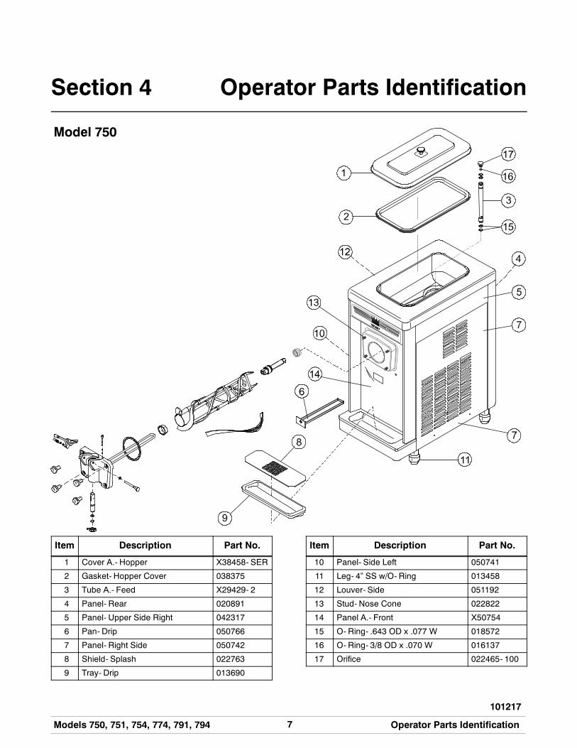
Section 4 Operator Parts Identification
Model 750
Item Description Part No.
1 Cover A.- Hopper X38458- SER
2 Gasket- Hopper Cover 038375
3 Tube A.- Feed X29429- 2
4 Panel- Rear 020891
5 Panel- Upper Side Right 042317
6 Pan- Drip 050766
7 Panel- Right Side 050742
8 Shield- Splash 022763
9 Tray- Drip 013690
Item Description Part No.
10 Panel- Side Left 050741
11 Leg- 4” SS w/O- Ring 013458
12 Louver- Side 051192
13 Stud- Nose Cone 022822
14 Panel A.- Front X50754
15 O- Ring- .643 OD x .077 W 018572
16 O- Ring- 3/8 OD x .070 W 016137
17 Orifice 022465- 100
8 Models 750, 751, 754, 774, 791, 794Operator Parts Identification
111101
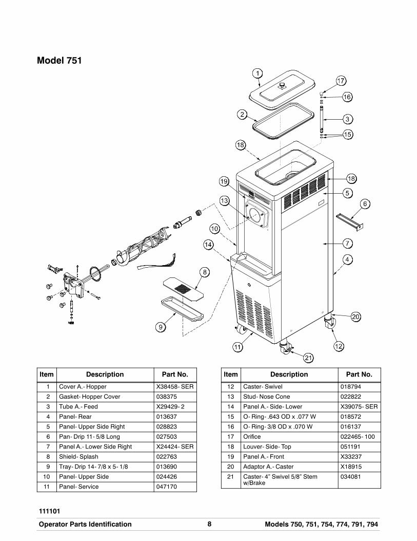
Model 751
Item Description Part No.
1 Cover A.- Hopper X38458- SER
2 Gasket- Hopper Cover 038375
3 Tube A.- Feed X29429- 2
4 Panel- Rear 013637
5 Panel- Upper Side Right 028823
6 Pan- Drip 11- 5/8 Long 027503
7 Panel A.- Lower Side Right X24424- SER
8 Shield- Splash 022763
9 Tray- Drip 14- 7/8 x 5- 1/8 013690
10 Panel- Upper Side 024426
11 Panel- Service 047170
Item Description Part No.
12 Caster- Swivel 018794
13 Stud- Nose Cone 022822
14 Panel A.- Side- Lower X39075- SER
15 O- Ring- .643 OD x .077 W 018572
16 O- Ring- 3/8 OD x .070 W 016137
17 Orifice 022465- 100
18 Louver- Side- Top 051191
19 Panel A.- Front X33237
20 Adaptor A.- Caster X18915
21 Caster- 4” Swivel 5/8” Stemw/Brake
034081
9Models 750, 751, 754, 774, 791, 794 Operator Parts Identification
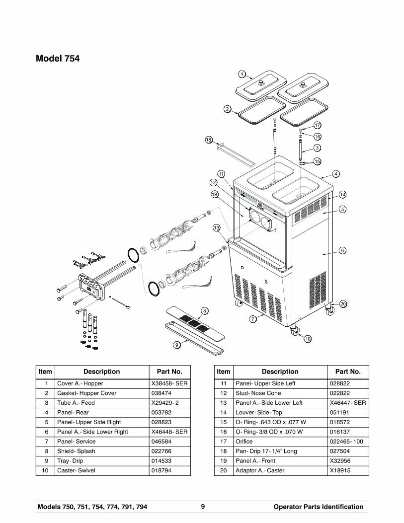
Model 754
Item Description Part No.
1 Cover A.- Hopper X38458- SER
2 Gasket- Hopper Cover 038474
3 Tube A.- Feed X29429- 2
4 Panel- Rear 053782
5 Panel- Upper Side Right 028823
6 Panel A.- Side Lower Right X46448- SER
7 Panel- Service 046584
8 Shield- Splash 022766
9 Tray- Drip 014533
10 Caster- Swivel 018794
Item Description Part No.
11 Panel- Upper Side Left 028822
12 Stud- Nose Cone 022822
13 Panel A.- Side Lower Left X46447- SER
14 Louver- Side- Top 051191
15 O- Ring- .643 OD x .077 W 018572
16 O- Ring- 3/8 OD x .070 W 016137
17 Orifice 022465- 100
18 Pan- Drip 17- 1/4” Long 027504
19 Panel A.- Front X32956
20 Adaptor A.- Caster X18915
10 Models 750, 751, 754, 774, 791, 794Operator Parts Identification
140616
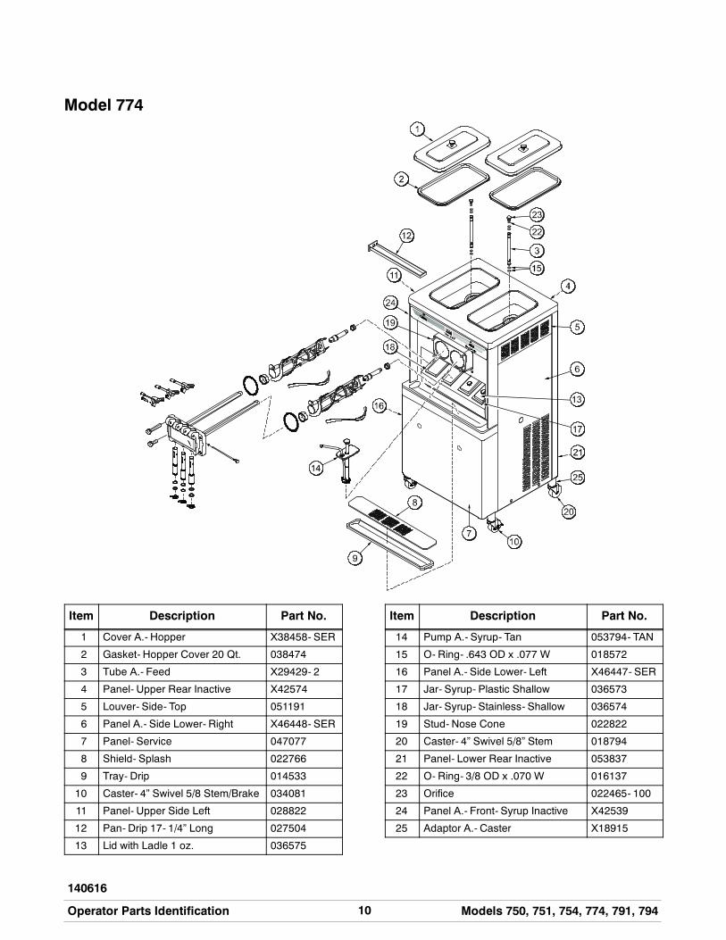
Model 774
Item Description Part No.
1 Cover A.- Hopper X38458- SER
2 Gasket- Hopper Cover 20 Qt. 038474
3 Tube A.- Feed X29429- 2
4 Panel- Upper Rear Inactive X42574
5 Louver- Side- Top 051191
6 Panel A.- Side Lower- Right X46448- SER
7 Panel- Service 047077
8 Shield- Splash 022766
9 Tray- Drip 014533
10 Caster- 4” Swivel 5/8 Stem/Brake 034081
11 Panel- Upper Side Left 028822
12 Pan- Drip 17- 1/4” Long 027504
13 Lid with Ladle 1 oz. 036575
Item Description Part No.
14 Pump A.- Syrup- Tan 053794- TAN
15 O- Ring- .643 OD x .077 W 018572
16 Panel A.- Side Lower- Left X46447- SER
17 Jar- Syrup- Plastic Shallow 036573
18 Jar- Syrup- Stainless- Shallow 036574
19 Stud- Nose Cone 022822
20 Caster- 4” Swivel 5/8” Stem 018794
21 Panel- Lower Rear Inactive 053837
22 O- Ring- 3/8 OD x .070 W 016137
23 Orifice 022465- 100
24 Panel A.- Front- Syrup Inactive X42539
25 Adaptor A.- Caster X18915
11Models 750, 751, 754, 774, 791, 794 Operator Parts Identification
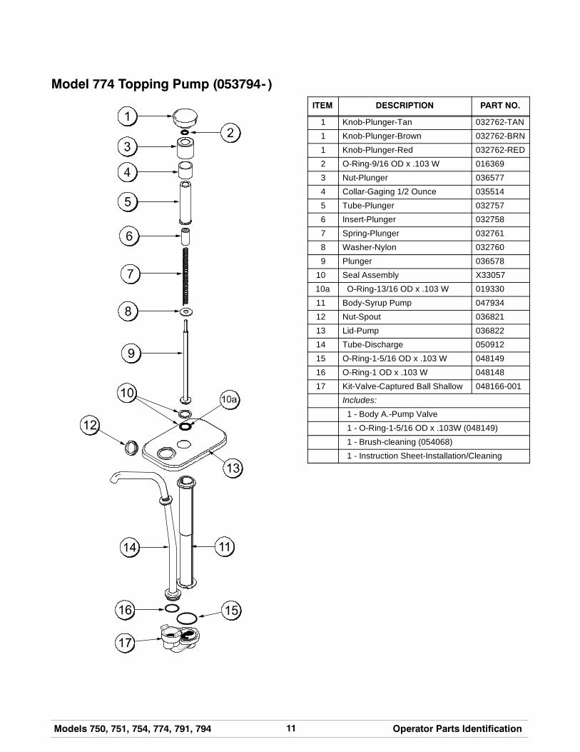
Model 774 Topping Pump (053794- )
ITEM DESCRIPTION PART NO.
1 Knob-Plunger-Tan 032762-TAN
1 Knob-Plunger-Brown 032762-BRN
1 Knob-Plunger-Red 032762-RED
2 O-Ring-9/16 OD x .103 W 016369
3 Nut-Plunger 036577
4 Collar-Gaging 1/2 Ounce 035514
5 Tube-Plunger 032757
6 Insert-Plunger 032758
7 Spring-Plunger 032761
8 Washer-Nylon 032760
9 Plunger 036578
10 Seal Assembly X33057
10a O-Ring-13/16 OD x .103 W 019330
11 Body-Syrup Pump 047934
12 Nut-Spout 036821
13 Lid-Pump 036822
14 Tube-Discharge 050912
15 O-Ring-1-5/16 OD x .103 W 048149
16 O-Ring-1 OD x .103 W 048148
17 Kit-Valve-Captured Ball Shallow 048166-001
Includes:
1 - Body A.-Pump Valve
1 - O-Ring-1-5/16 OD x .103W (048149)
1 - Brush-cleaning (054068)
1 - Instruction Sheet-Installation/Cleaning
12 Models 750, 751, 754, 774, 791, 794Operator Parts Identification
120613
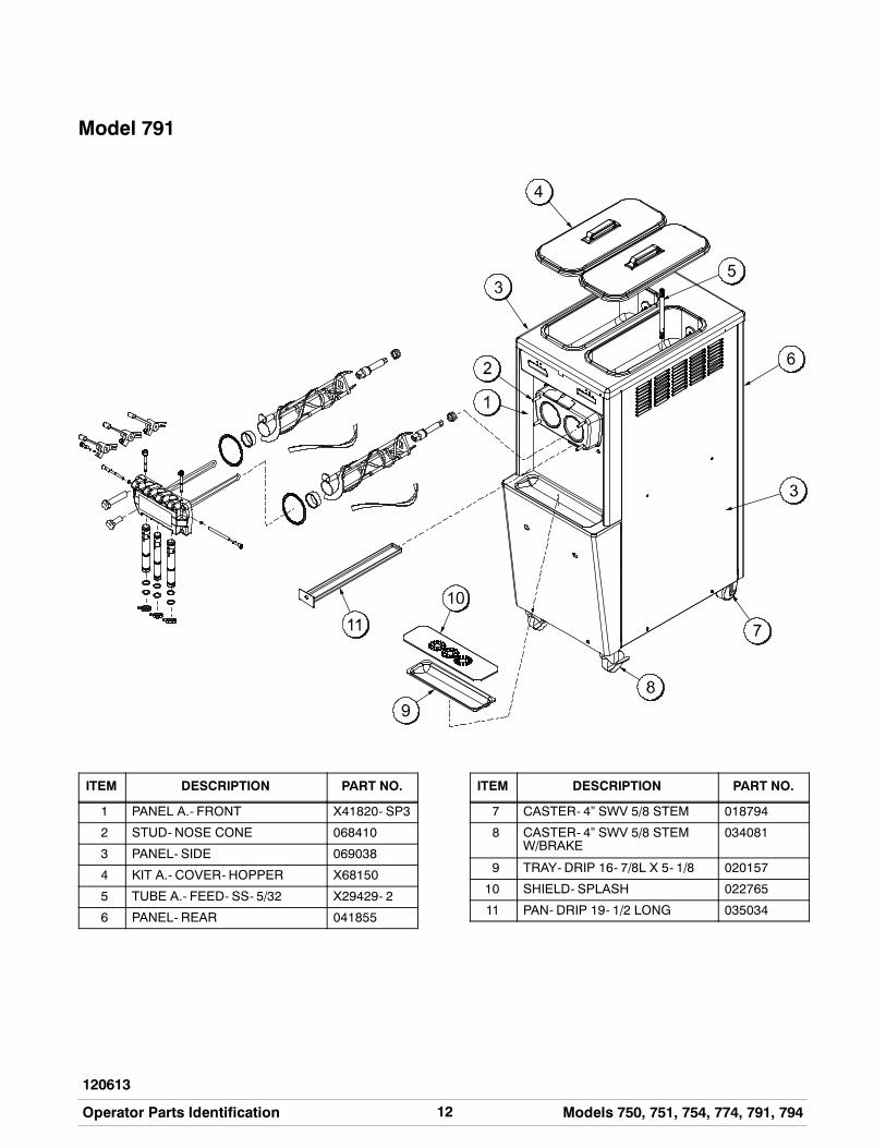
Model 791
ITEM DESCRIPTION PART NO.
1 PANEL A.- FRONT X41820- SP3
2 STUD- NOSE CONE 068410
3 PANEL- SIDE 069038
4 KIT A.- COVER- HOPPER X68150
5 TUBE A.- FEED- SS- 5/32 X29429- 2
6 PANEL- REAR 041855
ITEM DESCRIPTION PART NO.
7 CASTER- 4” SWV 5/8 STEM 018794
8 CASTER- 4” SWV 5/8 STEMW/BRAKE
034081
9 TRAY- DRIP 16- 7/8L X 5- 1/8 020157
10 SHIELD- SPLASH 022765
11 PAN- DRIP 19- 1/2 LONG 035034
13Models 750, 751, 754, 774, 791, 794 Operator Parts Identification
130508
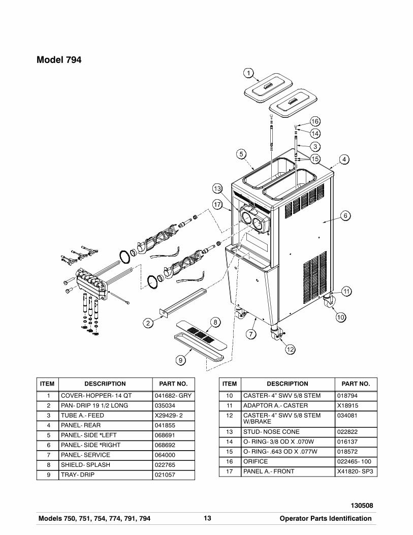
Model 794
ITEM DESCRIPTION PART NO.
1 COVER- HOPPER- 14 QT 041682- GRY
2 PAN- DRIP 19 1/2 LONG 035034
3 TUBE A.- FEED X29429- 2
4 PANEL- REAR 041855
5 PANEL- SIDE *LEFT 068691
6 PANEL- SIDE *RIGHT 068692
7 PANEL- SERVICE 064000
8 SHIELD- SPLASH 022765
9 TRAY- DRIP 021057
ITEM DESCRIPTION PART NO.
10 CASTER- 4” SWV 5/8 STEM 018794
11 ADAPTOR A.- CASTER X18915
12 CASTER- 4” SWV 5/8 STEMW/BRAKE
034081
13 STUD- NOSE CONE 022822
14 O- RING- 3/8 OD X .070W 016137
15 O- RING- .643 OD X .077W 018572
16 ORIFICE 022465- 100
17 PANEL A.- FRONT X41820- SP3
14 Models 750, 751, 754, 774, 791, 794Operator Parts Identification
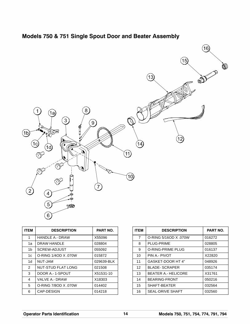
Models 750 & 751 Single Spout Door and Beater Assembly
ITEM DESCRIPTION PART NO.
1 HANDLE A.- DRAW X55096
1a DRAW HANDLE 028804
1b SCREW-ADJUST 055092
1c O-RING 1/4OD X .070W 015872
1d NUT-JAM 029639-BLK
2 NUT-STUD FLAT LONG 021508
3 DOOR A.- 1-SPOUT X51531-10
4 VALVE A.- DRAW X18303
5 O-RING 7/8OD X .070W 014402
6 CAP-DESIGN 014218
ITEM DESCRIPTION PART NO.
7 O-RING 5/16OD X .070W 016272
8 PLUG-PRIME 028805
9 O-RING-PRIME PLUG 016137
10 PIN A.- PIVOT X22820
11 GASKET-DOOR HT 4” 048926
12 BLADE- SCRAPER 035174
13 BEATER A.- HELICORE X31761
14 BEARING-FRONT 050216
15 SHAFT-BEATER 032564
16 SEAL-DRIVE SHAFT 032560
15Models 750, 751, 754, 774, 791, 794 Operator Parts Identification
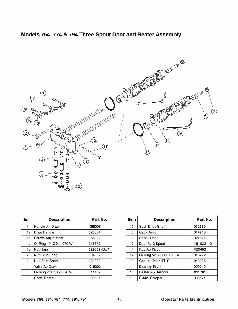
Models 754, 774 & 794 Three Spout Door and Beater Assembly
Item Description Part No.
1 Handle A.- Draw X55096
1a Draw Handle 028804
1b Screw- Adjustment 055092
1c O- Ring 1/4 OD x .070 W 015872
1d Nut- Jam 029639- BLK
2 Nut- Stud Long 034382
3 Nut- Stud Short 034383
4 Valve A.- Draw X18303
5 O- Ring 7/8 OD x .070 W 014402
6 Shaft- Beater 032564
Item Description Part No.
7 Seal- Drive Shaft 032560
8 Cap- Design 014218
9 Decal- Door 021521
10 Door A.- 3 Spout X51532- 12
11 Rod A.- Pivot X20683
12 O- Ring 5/16 OD x .070 W 016272
13 Gasket- Door HT 4” 048926
14 Bearing- Front 050216
15 Beater A.- Helicore X31761
16 Blade- Scraper 035174
16 Models 750, 751, 754, 774, 791, 794Operator Parts Identification
120124
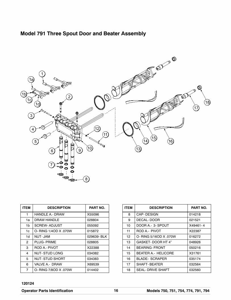
Model 791 Three Spout Door and Beater Assembly
ITEM DESCRIPTION PART NO.
1 HANDLE A.- DRAW X55096
1a DRAW HANDLE 028804
1b SCREW- ADJUST 055092
1c O- RING 1/4OD X .070W 015872
1d NUT- JAM 029639- BLK
2 PLUG- PRIME 028805
3 ROD A.- PIVOT X22388
4 NUT- STUD LONG 034382
5 NUT- STUD SHORT 034383
6 VALVE A.- DRAW X69539
7 O- RING 7/8OD X .070W 014402
ITEM DESCRIPTION PART NO.
8 CAP- DESIGN 014218
9 DECAL- DOOR 021521
10 DOOR A.- 3- SPOUT X49461- 4
11 ROD A.- PIVOT X22387
12 O- RING 5/16OD X .070W 016272
13 GASKET- DOOR HT 4” 048926
14 BEARING- FRONT 050216
15 BEATER A.- HELICORE X31761
16 BLADE- SCRAPER 035174
17 SHAFT- BEATER 032564
18 SEAL- DRIVE SHAFT 032560
17Models 750, 751, 754, 774, 791, 794 Operator Parts Identification
140718
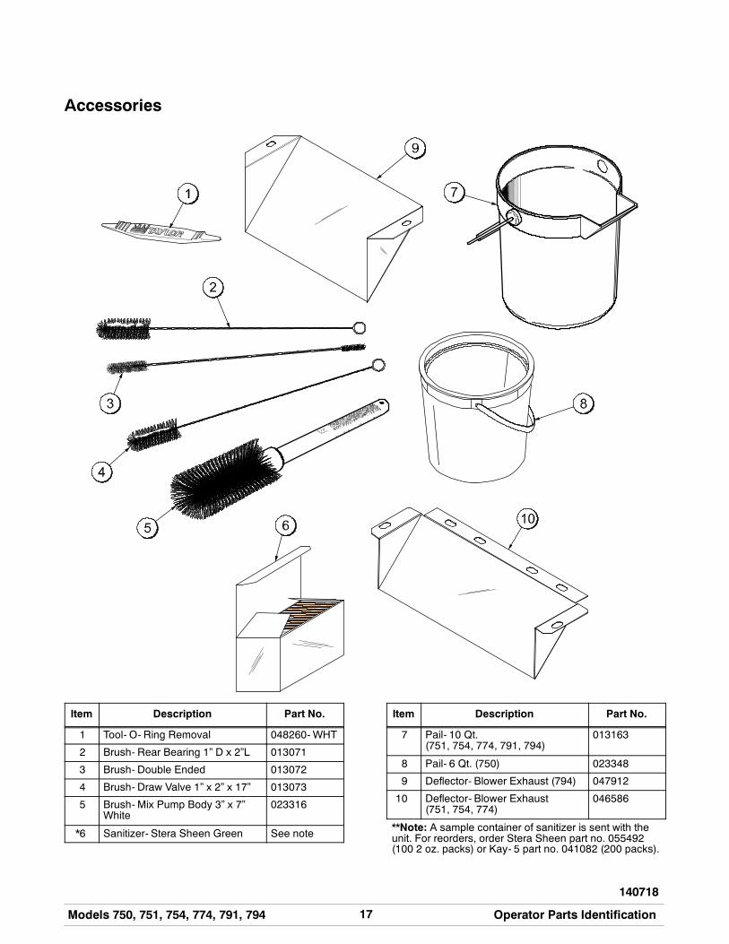
Accessories
Item Description Part No.
1 Tool- O- Ring Removal 048260-WHT
2 Brush- Rear Bearing 1” D x 2”L 013071
3 Brush- Double Ended 013072
4 Brush- Draw Valve 1” x 2” x 17” 013073
5 Brush- Mix Pump Body 3” x 7”White
023316
*6 Sanitizer- Stera Sheen Green See note
Item Description Part No.
7 Pail- 10 Qt.(751, 754, 774, 791, 794)
013163
8 Pail- 6 Qt. (750) 023348
9 Deflector- Blower Exhaust (794) 047912
10 Deflector- Blower Exhaust(751, 754, 774)
046586
**Note: A sample container of sanitizer is sent with theunit. For reorders, order Stera Sheen part no. 055492(100 2 oz. packs) or Kay- 5 part no. 041082 (200 packs).
18 Models 750, 751, 754, 774, 791, 794Important: To the Operator
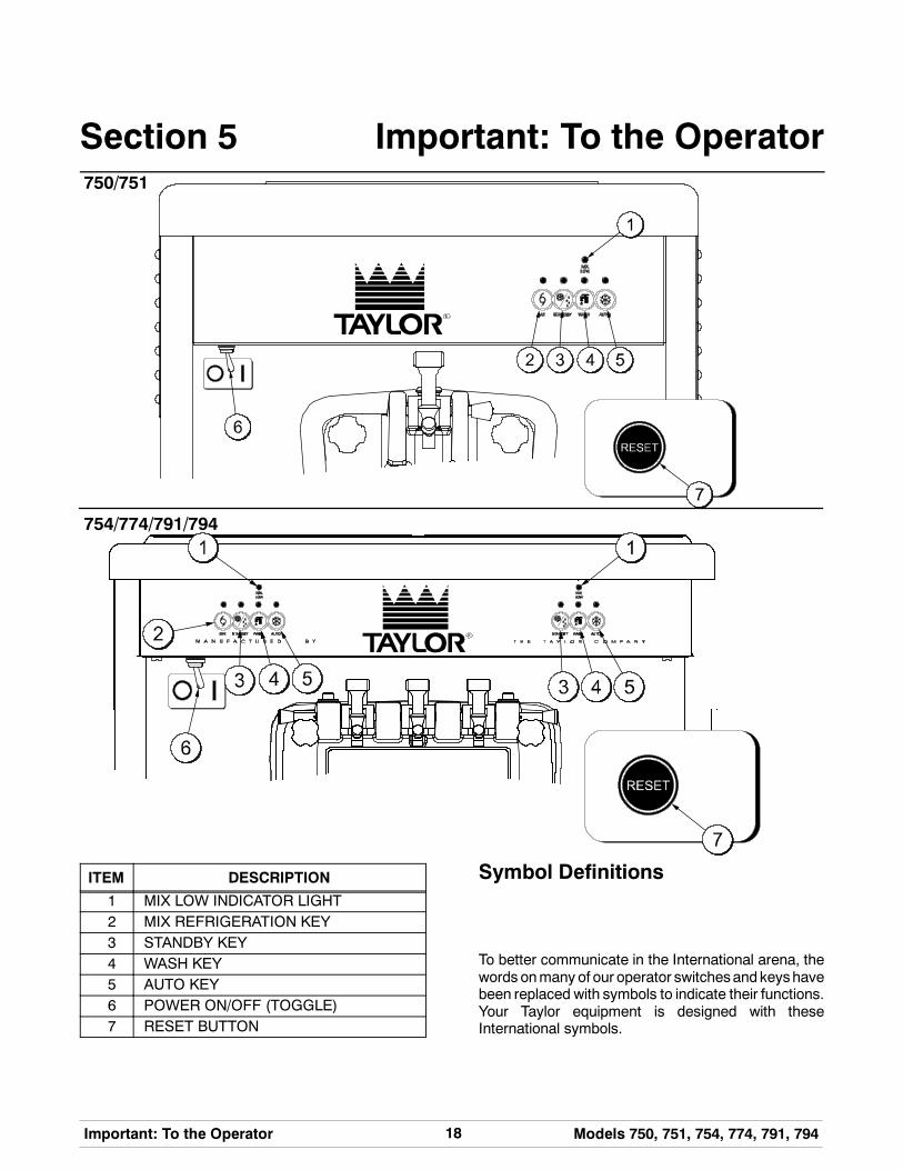
Section 5 Important: To the Operator750/751
754/774/791/794
ITEM DESCRIPTION
1 MIX LOW INDICATOR LIGHT2 MIX REFRIGERATION KEY3 STANDBY KEY4 WASH KEY5 AUTO KEY6 POWER ON/OFF (TOGGLE)7 RESET BUTTON
Symbol Definitions
To better communicate in the International arena, thewords onmany of our operator switchesand keyshavebeen replaced with symbols to indicate their functions.Your Taylor equipment is designed with theseInternational symbols.

19Models 750, 751, 754, 774, 791, 794 Important: To the Operator
130819
The following chart identifies the symbol definitions.
= OFF
= ON
= MIX
= STANDBY
= WASH
= AUTO
Power Switch
When placed in the ON position, the power switchallows SOFTECH control panel operation.
MIX LOW Indicator Light
Located on the front of the machine is a mix levelindicating light. When the light is flashing, it indicatesthat themix hopper has a low supply of mix and shouldbe refilled as soon as possible. Always maintain atleast 3” (7.6 cm) of mix in the hopper. If you neglect toadd mix, a freeze- up may occur. This will causeeventual damage to the beater, blades, drive shaft,and freezer door.
MIX REF Key
When the MIX REF key is pressed, the light comes onindicating the mix hopper refrigeration system isoperating. For the Models 754, 774, 791, and 794 theMIX REF is controlled by the left side of the freezer asviewed from the operator end. The MIX REF functioncannot be cancelled unless the AUTO or STANDBYmodes are cancelled first.
STANDBY Key
The Separate Hopper Refrigeration System (SHR)and the Cylinder Temperature Retention System(CTR) are standard features on these machines. TheSHR incorporates the use of a separate smallrefrigeration system to maintain the mix in the hopperbelow 40_(4.4_C) to assure bacteria control. TheCTRworks with theSHR tomaintain agood quality product.
During long “No Sale” periods, it is necessary to warmthe product in the freezing cylinder to approximately35_F to 40_F (1.7_C to 4.4_C) to prevent overbeatingand product breakdown.
To activate the SHR and CTR, press the STANDBYkey. Remove the air orifice and place the air tube (endwithout the hole) into the mix inlet hole.
IMPORTANT: Make sure the level of mix in thehopper is below the mix delivery hole in the feedtube. Failure to follow this instruction may result inlower product quality when normal operation isresumed.
When the STANDBY key is pressed, the light comeson, indicating the CTR (Cylinder TemperatureRetention System) has been activated. In theSTANDBY mode, the WASH and AUTO functions areautomatically cancelled. The MIX REF function isautomatically locked in to maintain the mix in thehopper.
To resume normal operation, press the AUTO key.When the unit cycles off, the product in the freezingcylinder will be at serving viscosity. At this time, placethe air tube (end with the hole) into the mix inlet holeand install the air orifice.
WASH Key
When the WASH key is pressed, the light comes on.This indicates beater motor operation. The STANDBYor AUTOmodes must be cancelled first to activate theWASH mode.
AUTO Key
When the AUTO key is pressed, the light comes on.This indicates that the main refrigeration system hasbeen activated. In the AUTO mode, the WASH orSTANDBY functions are automatically cancelled. TheMIX REF function is automatically locked in tomaintain the mix in the mix hopper.
Note: An indicating light and an audible tone willsound whenever a mode of operation has beenpressed. To cancel any function, press the key again.The light and mode of operation will shut off.
20 Models 750, 751, 754, 774, 791, 794Important: To the Operator
130819
Reset Button
On counter models, the reset button is located on theside of the unit. On console models, the reset buttonis located in the service panel. The reset protects thebeatermotor fromanoverload condition. If anoverloadoccurs, the reset mechanismwill trip. To properly resetthe freezer, press the AUTO key to cancel the cycle.Turn the power switch to the OFF position. Press thereset button firmly.
Donot usemetal objects to press the resetbutton. Failure to follow this instruction mayresult in electrocution.
Turn the power switch to the ON position. Press theWASH key and observe the freezer’s performance.Open the side access panel. Make sure the beatermotor is turning the drive shaft in a clockwise direction(from the operator end) without binding.
If the beatermotor is turning properly, press theWASHkey to cancel the cycle. Press theAUTOkey to resumenormal operation. If the freezer shuts down again,contact a service technician. (For Models 754, 774,791, and 794 press the AUTO key on both sides of theunit to resume normal operation.)
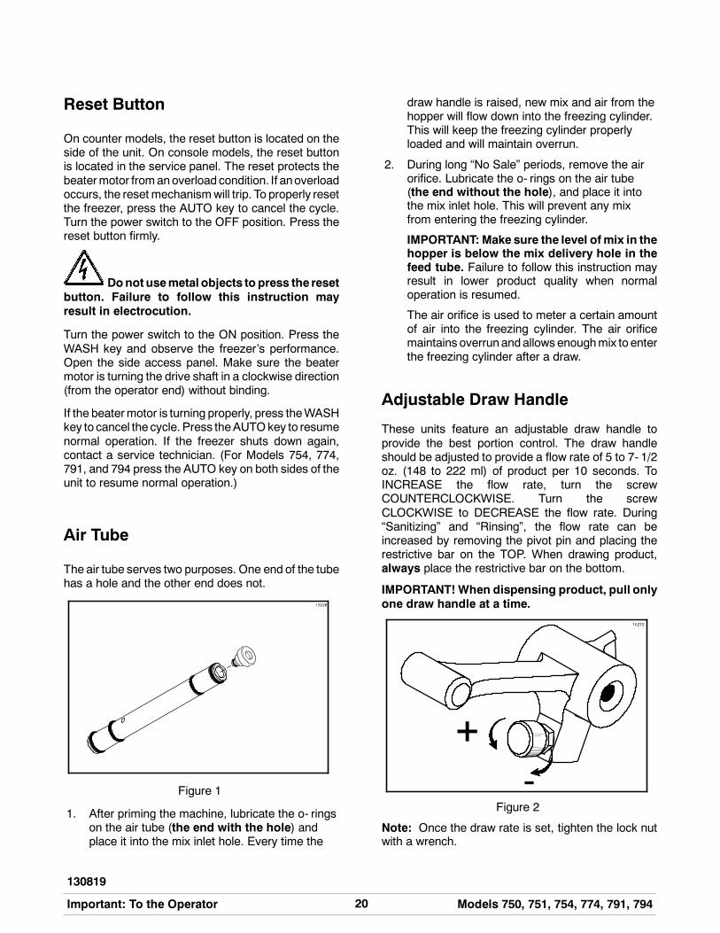
Air Tube
The air tube serves two purposes. One end of the tubehas a hole and the other end does not.
Figure 1
1. After priming the machine, lubricate the o- ringson the air tube (the end with the hole) andplace it into the mix inlet hole. Every time the
draw handle is raised, new mix and air from thehopper will flow down into the freezing cylinder.This will keep the freezing cylinder properlyloaded and will maintain overrun.
2. During long “No Sale” periods, remove the airorifice. Lubricate the o- rings on the air tube(the end without the hole), and place it intothe mix inlet hole. This will prevent any mixfrom entering the freezing cylinder.
IMPORTANT: Make sure the level ofmix in thehopper is below the mix delivery hole in thefeed tube. Failure to follow this instruction mayresult in lower product quality when normaloperation is resumed.
The air orifice is used to meter a certain amountof air into the freezing cylinder. The air orificemaintains overrunandallows enoughmix to enterthe freezing cylinder after a draw.
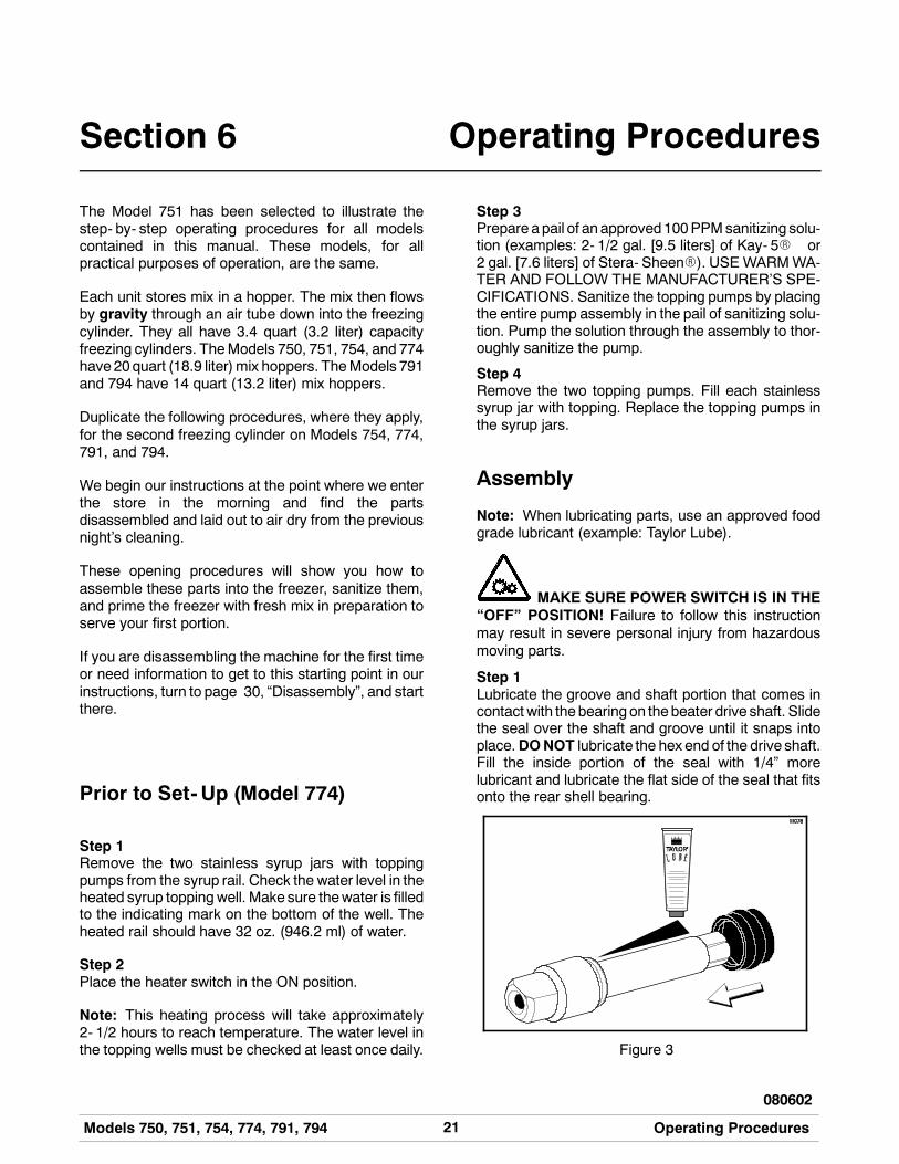
Adjustable Draw Handle
These units feature an adjustable draw handle toprovide the best portion control. The draw handleshould be adjusted to provide a flow rate of 5 to 7- 1/2oz. (148 to 222 ml) of product per 10 seconds. ToINCREASE the flow rate, turn the screwCOUNTERCLOCKWISE. Turn the screwCLOCKWISE to DECREASE the flow rate. During“Sanitizing” and “Rinsing”, the flow rate can beincreased by removing the pivot pin and placing therestrictive bar on the TOP. When drawing product,always place the restrictive bar on the bottom.
IMPORTANT!When dispensing product, pull onlyone draw handle at a time.
Figure 2
Note: Once the draw rate is set, tighten the lock nutwith a wrench.
21Models 750, 751, 754, 774, 791, 794 Operating Procedures
080602
Section 6 Operating Procedures
The Model 751 has been selected to illustrate thestep- by- step operating procedures for all modelscontained in this manual. These models, for allpractical purposes of operation, are the same.
Each unit stores mix in a hopper. The mix then flowsby gravity through an air tube down into the freezingcylinder. They all have 3.4 quart (3.2 liter) capacityfreezing cylinders. TheModels 750, 751, 754, and 774have20quart (18.9 liter)mix hoppers. TheModels 791and 794 have 14 quart (13.2 liter) mix hoppers.
Duplicate the following procedures, where they apply,for the second freezing cylinder on Models 754, 774,791, and 794.
We begin our instructions at the point where we enterthe store in the morning and find the partsdisassembled and laid out to air dry from the previousnight’s cleaning.
These opening procedures will show you how toassemble these parts into the freezer, sanitize them,and prime the freezer with fresh mix in preparation toserve your first portion.
If you are disassembling the machine for the first timeor need information to get to this starting point in ourinstructions, turn to page 30, “Disassembly”, and startthere.
Prior to Set-Up (Model 774)
Step 1Remove the two stainless syrup jars with toppingpumps from the syrup rail. Check the water level in theheated syrup toppingwell. Make sure thewater is filledto the indicating mark on the bottom of the well. Theheated rail should have 32 oz. (946.2 ml) of water.
Step 2Place the heater switch in the ON position.
Note: This heating process will take approximately2- 1/2 hours to reach temperature. The water level inthe topping wells must be checked at least once daily.
Step 3Prepareapail of anapproved100PPMsanitizing solu-tion (examples: 2- 1/2 gal. [9.5 liters] of Kay- 5R or2 gal. [7.6 liters] of Stera- SheenR). USE WARMWA-TER AND FOLLOW THE MANUFACTURER’S SPE-CIFICATIONS. Sanitize the topping pumps by placingthe entire pump assembly in the pail of sanitizing solu-tion. Pump the solution through the assembly to thor-oughly sanitize the pump.
Step 4Remove the two topping pumps. Fill each stainlesssyrup jar with topping. Replace the topping pumps inthe syrup jars.
Assembly
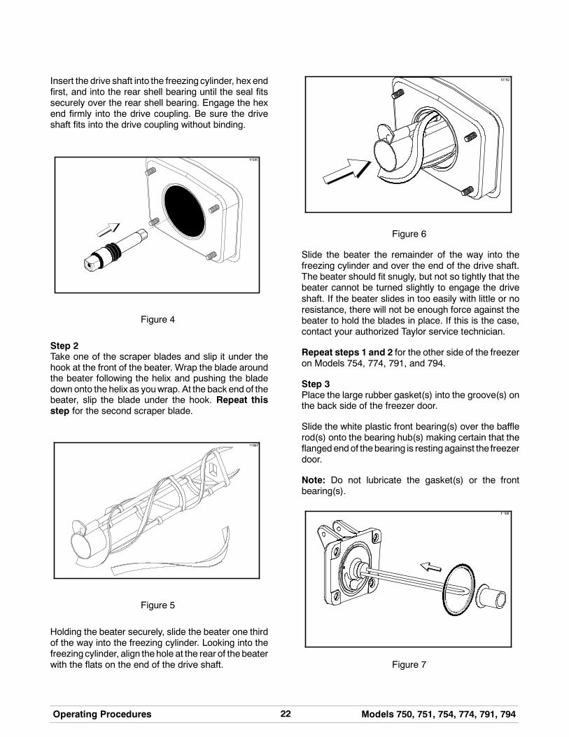
Note: When lubricating parts, use an approved foodgrade lubricant (example: Taylor Lube).
MAKE SURE POWER SWITCH IS IN THE“OFF” POSITION! Failure to follow this instructionmay result in severe personal injury from hazardousmoving parts.
Step 1Lubricate the groove and shaft portion that comes incontact with thebearingon thebeater drive shaft. Slidethe seal over the shaft and groove until it snaps intoplace.DONOT lubricate the hex end of the drive shaft.Fill the inside portion of the seal with 1/4” morelubricant and lubricate the flat side of the seal that fitsonto the rear shell bearing.
Figure 3
22 Models 750, 751, 754, 774, 791, 794Operating Procedures
Insert the drive shaft into the freezing cylinder, hex endfirst, and into the rear shell bearing until the seal fitssecurely over the rear shell bearing. Engage the hexend firmly into the drive coupling. Be sure the driveshaft fits into the drive coupling without binding.
Figure 4
Step 2Take one of the scraper blades and slip it under thehook at the front of the beater. Wrap the blade aroundthe beater following the helix and pushing the bladedown onto the helix as youwrap. At the back end of thebeater, slip the blade under the hook. Repeat thisstep for the second scraper blade.
Figure 5
Holding the beater securely, slide the beater one thirdof the way into the freezing cylinder. Looking into thefreezing cylinder, align thehole at the rear of thebeaterwith the flats on the end of the drive shaft.
Figure 6
Slide the beater the remainder of the way into thefreezing cylinder and over the end of the drive shaft.The beater should fit snugly, but not so tightly that thebeater cannot be turned slightly to engage the driveshaft. If the beater slides in too easily with little or noresistance, there will not be enough force against thebeater to hold the blades in place. If this is the case,contact your authorized Taylor service technician.
Repeat steps 1 and 2 for the other side of the freezeron Models 754, 774, 791, and 794.
Step 3Place the large rubber gasket(s) into the groove(s) onthe back side of the freezer door.
Slide the white plastic front bearing(s) over the bafflerod(s) onto the bearing hub(s) making certain that theflangedendof thebearing is resting against the freezerdoor.
Note: Do not lubricate the gasket(s) or the frontbearing(s).
Figure 7
23Models 750, 751, 754, 774, 791, 794 Operating Procedures
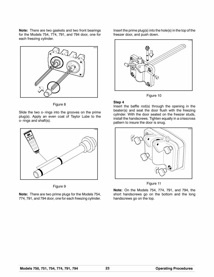
Note: There are two gaskets and two front bearingsfor the Models 754, 774, 791, and 794 door, one foreach freezing cylinder.
Figure 8
Slide the two o- rings into the grooves on the primeplug(s). Apply an even coat of Taylor Lube to theo- rings and shaft(s).
Figure 9
Note: There are two prime plugs for the Models 754,774, 791, and 794 door, one for each freezing cylinder.
Insert the prime plug(s) into the hole(s) in the top of thefreezer door, and push down.
Figure 10
Step 4Insert the baffle rod(s) through the opening in thebeater(s) and seat the door flush with the freezingcylinder. With the door seated on the freezer studs,install the handscrews. Tighten equally in a crisscrosspattern to insure the door is snug.
Figure 11
Note: On the Models 754, 774, 791, and 794, theshort handscrews go on the bottom and the longhandscrews go on the top.

24 Models 750, 751, 754, 774, 791, 794Operating Procedures
101109
Step 5Install the draw valve(s). Slide the two o- rings into thegrooves on the draw valve(s), and lubricate.
Figure 12
Note: Models 754, 774, 791, and794have threedrawvalves.
Lubricate the inside of the freezer door spout(s), topand bottom, and insert the draw valve(s) from thebottom until the slot in the draw valve(s) comes intoview.
Figure 13
Step 6Install the adjustable draw handle(s). Slide the o- ringinto the groove on the pivot pin, and lubricate.
Figure 14
Slide the fork over the bar in the slot of the draw valve.Secure with pivot pin.
Figure 15
Note: Models 754, 774, 791, and794have threedrawhandles. Slide the fork of the draw handle in the slot ofthe draw valve, starting from the right. Slide the pivotpin through each draw handle as you insert them intothe draw valves.
Note: These units feature adjustable draw handles toprovide the best portion control. The draw handles canbe adjusted for different flow rates. See page 20 formore information on adjusting these handles.
25Models 750, 751, 754, 774, 791, 794 Operating Procedures
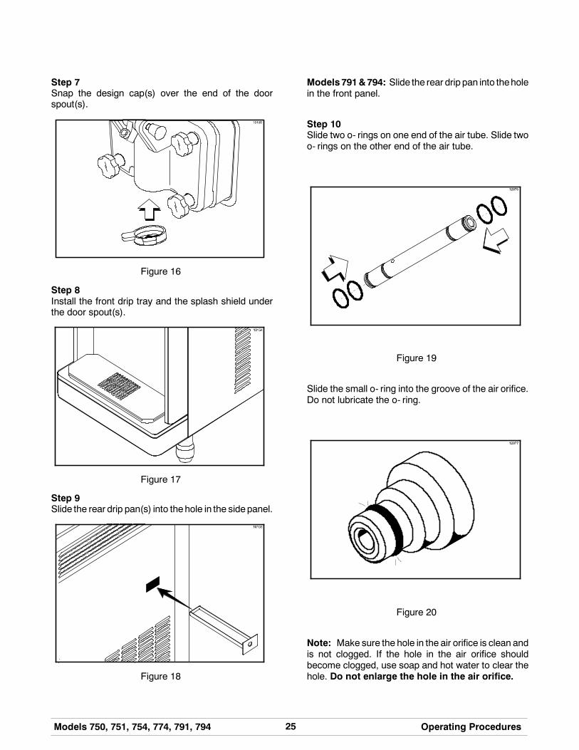
Step 7Snap the design cap(s) over the end of the doorspout(s).
Figure 16
Step 8Install the front drip tray and the splash shield underthe door spout(s).
Figure 17
Step 9Slide the rear drip pan(s) into thehole in the sidepanel.
Figure 18
Models791&794: Slide the rear drip pan into theholein the front panel.
Step 10Slide two o- rings on one end of the air tube. Slide twoo- rings on the other end of the air tube.
Figure 19
Slide the small o- ring into the groove of the air orifice.Do not lubricate the o- ring.
Figure 20
Note: Make sure the hole in the air orifice is clean andis not clogged. If the hole in the air orifice shouldbecome clogged, use soap and hot water to clear thehole. Do not enlarge the hole in the air orifice.
26 Models 750, 751, 754, 774, 791, 794Operating Procedures
130118
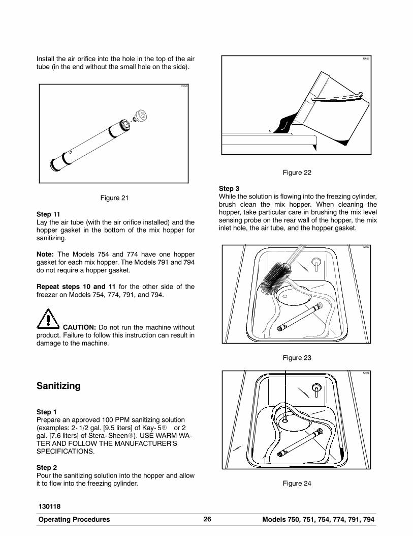
Install the air orifice into the hole in the top of the airtube (in the end without the small hole on the side).
Figure 21
Step 11Lay the air tube (with the air orifice installed) and thehopper gasket in the bottom of the mix hopper forsanitizing.
Note: The Models 754 and 774 have one hoppergasket for each mix hopper. The Models 791 and 794do not require a hopper gasket.
Repeat steps 10 and 11 for the other side of thefreezer on Models 754, 774, 791, and 794.
CAUTION: Do not run the machine withoutproduct. Failure to follow this instruction can result indamage to the machine.
Sanitizing
Step 1Prepare an approved 100 PPM sanitizing solution(examples: 2- 1/2 gal. [9.5 liters] of Kay- 5R or 2gal. [7.6 liters] of Stera- SheenR). USE WARM WA-TER AND FOLLOW THE MANUFACTURER’SSPECIFICATIONS.
Step 2Pour the sanitizing solution into the hopper and allowit to flow into the freezing cylinder.
Figure 22
Step 3While the solution is flowing into the freezing cylinder,brush clean the mix hopper. When cleaning thehopper, take particular care in brushing the mix levelsensing probe on the rear wall of the hopper, the mixinlet hole, the air tube, and the hopper gasket.
Figure 23
Figure 24

27Models 750, 751, 754, 774, 791, 794 Operating Procedures
Figure 25
Step 4Place the power switch in the ON position.
Figure 26
Step 5Press the WASH key. This will cause the sanitizingsolution in the freezing cylinder to agitate. Allow it toagitate for five minutes.
Figure 27
Step 6Place an empty pail beneath the door spout and raisethe prime plug.
Figure 28
Step 7When a steady stream of sanitizing solution is flowingfrom the prime plug opening in the bottom of thefreezer door, lower the draw handle. Draw off all thesanitizing solution.
Figure 29
Note: On the Models 754, 774, 791, and 794,momentarily pull the center draw handle down tosanitize the center door spout.
Step 8Once the sanitizer stops flowing from the door spout,raise the draw handle and press the WASH key,cancelling the beater motor operation.
Note: You have just sanitized the freezer. Be sureyour hands are sanitized before continuing theseinstructions.
28 Models 750, 751, 754, 774, 791, 794Operating Procedures
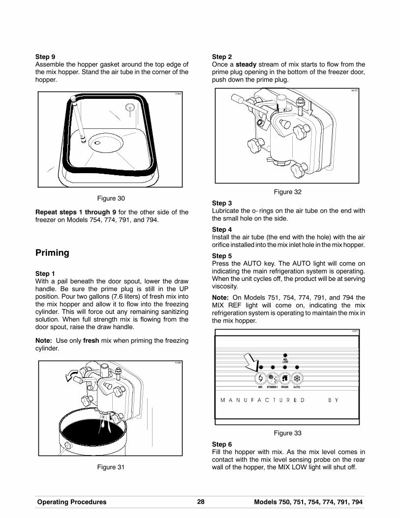
Step 9Assemble the hopper gasket around the top edge ofthe mix hopper. Stand the air tube in the corner of thehopper.
Figure 30
Repeat steps 1 through 9 for the other side of thefreezer on Models 754, 774, 791, and 794.
Priming
Step 1With a pail beneath the door spout, lower the drawhandle. Be sure the prime plug is still in the UPposition. Pour two gallons (7.6 liters) of fresh mix intothe mix hopper and allow it to flow into the freezingcylinder. This will force out any remaining sanitizingsolution. When full strength mix is flowing from thedoor spout, raise the draw handle.
Note: Use only fresh mix when priming the freezingcylinder.
Figure 31
Step 2Once a steady stream of mix starts to flow from theprime plug opening in the bottom of the freezer door,push down the prime plug.
Figure 32
Step 3Lubricate the o- rings on the air tube on the end withthe small hole on the side.
Step 4Install the air tube (the end with the hole) with the airorifice installed into themix inlet hole in themix hopper.
Step 5Press the AUTO key. The AUTO light will come onindicating the main refrigeration system is operating.When the unit cycles off, the product will be at servingviscosity.
Note: On Models 751, 754, 774, 791, and 794 theMIX REF light will come on, indicating the mixrefrigeration system is operating to maintain the mix inthe mix hopper.
Figure 33
Step 6Fill the hopper with mix. As the mix level comes incontact with the mix level sensing probe on the rearwall of the hopper, the MIX LOW light will shut off.
29Models 750, 751, 754, 774, 791, 794 Operating Procedures
140718
Step 7Place the mix hopper cover in position over the mixhopper.
Repeat steps 1 through 7 for the other side of thefreezer on Models 754, 774, 791, and 794.
Closing Procedure
To disassemble your unit, the following items will beneeded:
S Two cleaning pailsS Sanitized stainless steel rerun can with lidS Necessary brushes (provided with freezer)S CleanerS Single service towels
Draining Product From TheFreezing Cylinder
Step 1Press the AUTO key, cancelling compressor andbeater motor operation.
Press the MIX REF key, cancelling the mix hopperrefrigeration system.
Step 2Remove the hopper cover, hopper gasket and air tube.Take these parts to the sink for cleaning.
Step 3If local health codes permit the use of rerun, placea sanitized, NSF approved stainless steel reruncontainer beneath the door spout. Press the WASHkey and lower the draw handle. Drain the remainingproduct from the freezing cylinder and mix hopper.When the flow of product stops, press the WASH keyand raise the draw handle. Place the sanitized lid onthe rerun container and place it in the walk- in cooler.
Note: If local health codesDONOTpermit theuseof rerun, the product must be discarded. Drain theproduct into a pail and properly discard it.
Repeat steps 1 through 3 for the other side of thefreezer on Models 754, 774, 791, and 794.
ALWAYS FOLLOW LOCAL HEALTH CODES.
Rinsing
Step 1Pour twogallons (7.6 liters) of cool cleanwater into themix hopper. With the brushes provided, scrub the mixhopper, mix inlet hole and mix level sensing probe.
Step 2With apail beneath thedoor spout, raise theprimeplugand press the WASH key.
Step 3When a steady stream of rinse water is flowing fromthe prime plug opening in the bottom of the freezerdoor, lower the draw handle. Drain all the rinse waterfrom the freezing cylinder, raise the draw handle andpress the WASH key cancelling the WASH mode.
Repeat steps 1 through 3 for the other side of thefreezer on Models 754, 774, 791, and 794.
Cleaning
Step 1Prepare an approved 100 PPM cleaning solution(examples: 2- 1/2 gal. [9.5 liters] of Kay- 5R or 2gal. [7.6 liters] of Stera- SheenR). USE WARM WA-TER AND FOLLOW THE MANUFACTURER’SSPECIFICATIONS.
Step 2Push down the prime plug. Pour the cleaning solutioninto the mix hopper.
Step 3While the solution is flowing into the freezing cylinder,brush clean the mix hopper, mix level sensing probe,and the mix inlet hole.
Step 4Press the WASH key. This will cause the cleaningsolution in the freezing cylinder to agitate.
Step 5Place an empty pail beneath the door spout and raisethe prime plug.
30 Models 750, 751, 754, 774, 791, 794Operating Procedures
080324
Step 6When a steady stream of cleaning solution is flowingfrom the prime plug opening in the bottom of thefreezer door, lower the draw handle. Draw off all of thesolution.
Step 7Once the cleaner stops flowing from the door spout,raise the draw handle and press the WASH keycancelling the WASH mode.
Repeat steps 1 through 7 for the other side of thefreezer on Models 754, 774, 791, and 794.
Disassembly
MAKE SURE POWER SWITCH IS IN THE“OFF” POSITION! Failure to follow this instructionmay result in severe personal injury from hazardousmoving parts.
Step 1Remove the handscrews, freezer door(s), beater(s),scraper blades, and drive shaft(s) from the freezingcylinder(s). Take these parts to the sink for cleaning.
Step 2Remove the front drip tray and the splash shield.
Brush Cleaning
Step 1Prepare a sink with an approved cleaning solution (ex-amples: Kay- 5r or Stera- Sheenr). USE WARMWA-TER AND FOLLOW THE MANUFACTURER’S SPE-CIFICATIONS. If another approved cleaner is used,dilute it according to the label instructions. (IMPORT-ANT: Follow the label directions. Too STRONG of asolution can cause parts damage, while too MILD of asolution will not provide adequate cleaning.) Makesure all brushes providedwith the freezer are availablefor brush cleaning.
Step 2Remove the seal(s) from the drive shaft(s).
Step 3From the freezer door(s) remove:
S gasket(s)S front bearing(s)S pivot pin(s)
S adjustable draw handle(s)S design cap(s)S draw valve(s)S prime plug(s)S all o- rings
Note: To remove o- rings, use a single service towelto grasp the o- ring. Apply pressure in an upwarddirection until the o- ring pops out of its groove. Withthe other hand, push the top of the o- ring forward andit will roll out of the groove and can be easily removed.If there is more than one o- ring to be removed, alwaysremove the rear o- ring first. This will allow the o- ringto slide over the forward rings without falling into theopen grooves.
Step 4Remove the o- rings from the air tube(s) and airorifice(s).
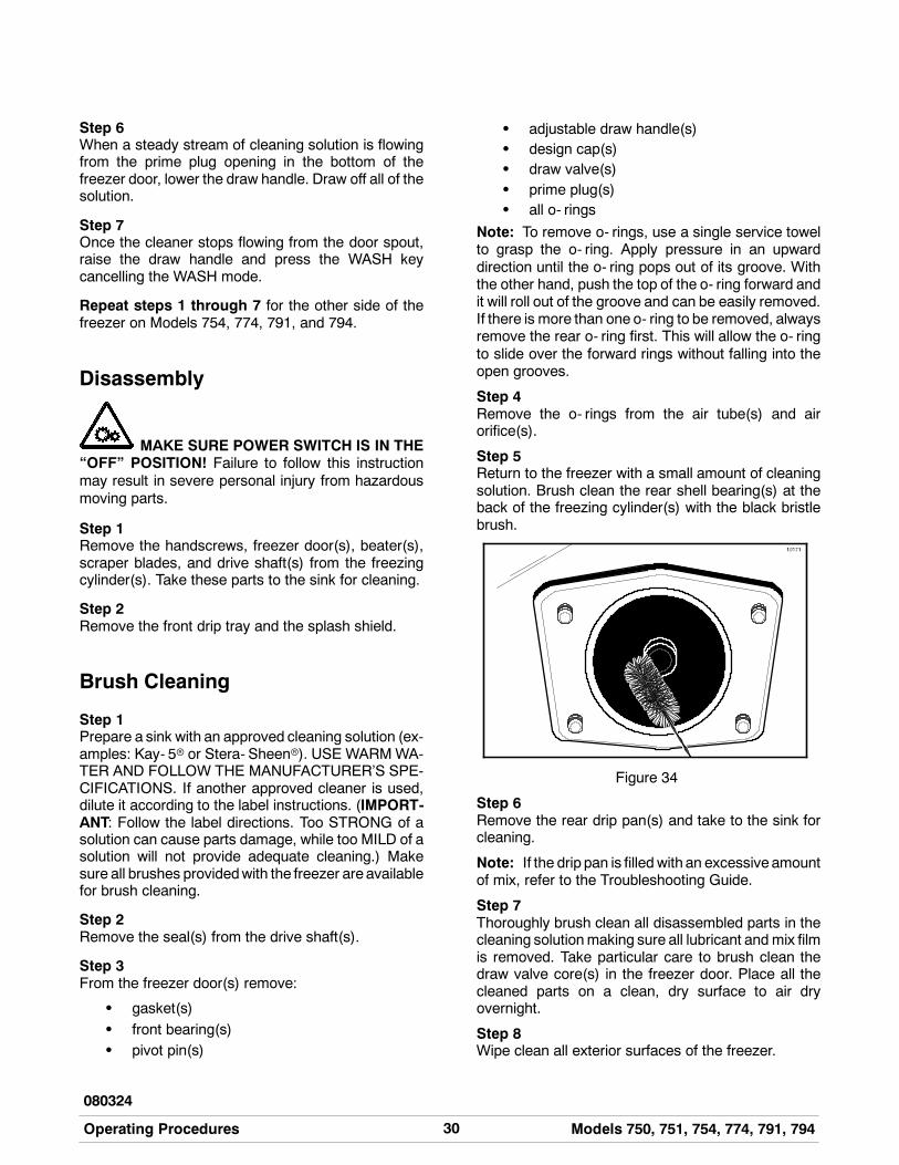
Step 5Return to the freezer with a small amount of cleaningsolution. Brush clean the rear shell bearing(s) at theback of the freezing cylinder(s) with the black bristlebrush.
Figure 34
Step 6Remove the rear drip pan(s) and take to the sink forcleaning.
Note: If the drip pan is filled with an excessive amountof mix, refer to the Troubleshooting Guide.
Step 7Thoroughly brush clean all disassembled parts in thecleaning solutionmaking sure all lubricant and mix filmis removed. Take particular care to brush clean thedraw valve core(s) in the freezer door. Place all thecleaned parts on a clean, dry surface to air dryovernight.
Step 8Wipe clean all exterior surfaces of the freezer.
31Models 750, 751, 754, 774, 791, 794 Important: Operator Checklist
061122
Section 7 Important: Operator Checklist
During Cleaning and Sanitizing
Cleaning and sanitizing schedules are governedby federal, state, or local regulatory agencies,and must be followed accordingly. If the unithas a “Standby mode”, it must not be used inlieu of proper cleaning and sanitizingprocedures and frequencies set forth by theruling health authority. The following checkpoints should be stressed during the cleaningand sanitizing operations.
CLEANING AND SANITIZING MUST BEPERFORMED DAILY.
ALWAYS FOLLOW LOCAL HEALTH CODES.
Troubleshooting Bacterial Count
j 1. Thoroughly clean and sanitize machineregularly, including complete disassembly andbrush cleaning.
j 2. Use all brushes supplied for thorough cleaning.The brushes are specially designed to reach allmix passageways.
j 3. Use the white bristle brush to clean the mix inlethole which extends from the mix hopper downto the rear of the freezing cylinder.
j 4. Use the black bristle brush to thoroughly cleanthe rear shell bearing located at the rear of thefreezing cylinder. Be sure to have a generousamount of cleaning solution on the brush.
j 5. IF LOCAL HEALTH CODES PERMIT THEUSE OF RERUN, make sure the mix rerun isstored in a sanitized, covered stainless steelcontainer and used the following day. DO NOTprime the machine with rerun. When usingrerun, skim off the foam and discard. Mix thererunwith freshmix in a ratio of 50/50 during thedays operation.
j 6. On a designated day of theweek, run themix aslow as feasible and discard it after closing. Thiswill break the rerun cycle and reduce thepossibility of high bacteria and coliform counts.
j 7. Properly prepare the cleaning and sanitizingsolutions. Read and follow label directionscarefully. Too strong of a solution may damagethe parts and too weak of a solution will not doan adequate job of cleaning or sanitizing.
j 8. The temperature of the mix in the mix hopperand walk- in cooler should be below 40_F.(4.4_C.).
Regular Maintenance Checks
j 1. Replace scraper blades that are nicked ordamaged. Before installing the beaterassembly, be certain that scraper blades areproperly attached to the helix.
j 2. Check the rear shell bearing for signs of wear(excessive mix leakage in rear drip pan) and becertain it is properly cleaned.
j 3. Using a screwdriver and cloth towel, keep therear shell bearing and the 3/4 hex drive couplingclean and free of lubricant and mix deposits.
j 4. Dispose of o- rings and seals if they are worn,torn, or fit too loosely, and replace with newones.
j 5. Follow all lubricating procedures as outlined in“Assembly”.
32 Models 750, 751, 754, 774, 791, 794Important: Operator Checklist
080324
j 6. If your machine is air cooled, check thecondensers for accumulation of dirt and lint.Dirty condensers will reduce the efficiency andcapacity of themachine. Condensers should becleaned monthly with a soft brush. Never usescrewdrivers or other metal probes to cleanbetween the fins.Note: For machines equipped with an air filter,it will be necessary to vacuum clean the filterson a monthly schedule.
Caution: Always disconnectelectrical power prior to cleaning thecondenser. Failure to follow this instructionmay result in electrocution.
j 7. If your machine is equipped with an auxiliaryrefrigeration system, check the auxiliarycondenser for accumulation of dirt and lint. Dirtycondensers will reduce the refrigerationcapacity of the mix hopper. Condensers mustbe cleanedmonthlywith a soft brush. Neverusescrewdrivers or other metal probes to cleanbetween the fins. Failure to follow thisinstruction may result in electrocution.
Caution: Always disconnectelectrical power prior to cleaning thecondenser. Failure to follow this instructionmay result in electrocution.
j 8. If yourmachine iswater cooled, check thewaterlines for kinks or leaks. Kinks can occur whenthe machine is moved back and forth forcleaning or maintenance purposes.Deteriorated or cracked water lines should bereplaced only by an authorized Taylordistributor.
Winter Storage
If the placeof business is to be closedduring thewintermonths, it is important to protect the freezer byfollowing certain precautions, particularly if thebuilding is subject to freezing conditions.
Disconnect the freezer from the main power source toprevent possible electrical damage.
On water cooled freezers, disconnect the watersupply. Relieve pressure on the spring in the watervalve. Use air pressure on the outlet side to blow outany water remaining in the condenser. This isextremely important. Failure to follow this proceduremay cause severe and costly damage to therefrigeration system.
Your local Taylor Distributor can perform this winterstorage service for you.
Wrap detachable parts of the freezer such as beater,blades, drive shaft, and freezer door, and place theminaprotecteddry place. Rubber trimparts andgasketscan be protected by wrapping them withmoisture- proof paper. All parts should be thoroughlycleaned of dried mix or lubrication which attract miceand other vermin.
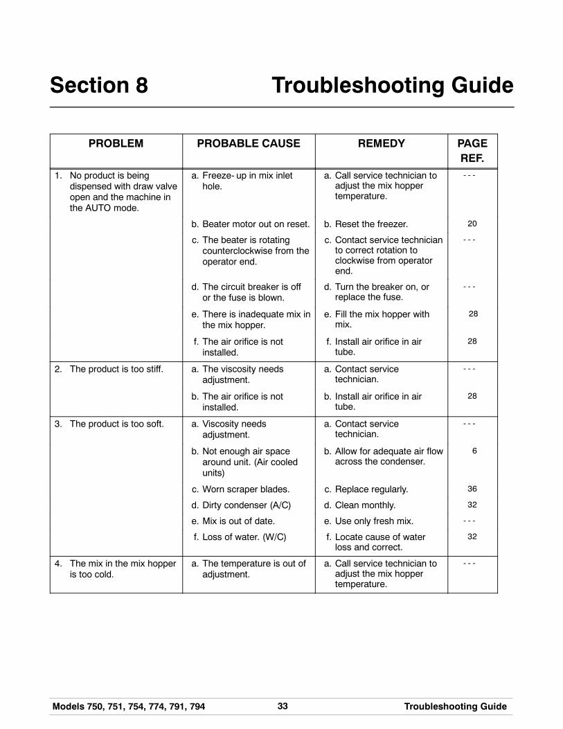
33Models 750, 751, 754, 774, 791, 794 Troubleshooting Guide
Section 8 Troubleshooting Guide
PROBLEM PROBABLE CAUSE REMEDY PAGEREF.
1. No product is beingdispensed with draw valveopen and the machine inthe AUTO mode.
a. Freeze- up in mix inlethole.
a. Call service technician toadjust the mix hoppertemperature.
- - -
b. Beater motor out on reset. b. Reset the freezer. 20
c. The beater is rotatingcounterclockwise from theoperator end.
c. Contact service technicianto correct rotation toclockwise from operatorend.
- - -
d. The circuit breaker is offor the fuse is blown.
d. Turn the breaker on, orreplace the fuse.
- - -
e. There is inadequate mix inthe mix hopper.
e. Fill the mix hopper withmix.
28
f. The air orifice is notinstalled.
f. Install air orifice in airtube.
28
2. The product is too stiff. a. The viscosity needsadjustment.
a. Contact servicetechnician.
- - -
b. The air orifice is notinstalled.
b. Install air orifice in airtube.
28
3. The product is too soft. a. Viscosity needsadjustment.
a. Contact servicetechnician.
- - -
b. Not enough air spacearound unit. (Air cooledunits)
b. Allow for adequate air flowacross the condenser.
6
c. Worn scraper blades. c. Replace regularly. 36
d. Dirty condenser (A/C) d. Clean monthly. 32
e. Mix is out of date. e. Use only fresh mix. - - -
f. Loss of water. (W/C) f. Locate cause of waterloss and correct.
32
4. The mix in the mix hopperis too cold.
a. The temperature is out ofadjustment.
a. Call service technician toadjust the mix hoppertemperature.
- - -

34 Models 750, 751, 754, 774, 791, 794Troubleshooting Guide
PROBLEM PROBABLE CAUSE REMEDY PAGEREF.
5. The mix in the mix hopperis too warm.
a. The temperature is out ofadjustment.
a. Call service technician toadjust the mix hoppertemperature.
- - -
b. Missing or defective mixhopper gasket.
b. Replace/install the gasketaround the mix hopper.
28
c. The mix hopper cover isnot in position.
c. Place the cover inposition.
29
d. The MIX REF light is notlit.
d. Press the MIX REF key. 19
6. The drive shaft is stuck inthe drive coupling.
a. Rounded corners of driveshaft, coupling, or both.
a. Call service technician tocorrect cause, and toreplace the necessarycomponents. Do notlubricate the hex end ofthe drive shaft.
- - -
b. Mix and lubricant collectedin the drive coupling.
b. Brush clean the rear shellbearing area regularly.
30
7. The freezing cylinder wallsare scored.
a. The beater assembly isbent.
a. Call service technician torepair or replace thebeater and to correct thecause of insufficient mixin the freezing cylinder.
- - -
b. The front bearing ismissing or worn on thefreezer door.
b. Install or replace the frontbearing.
22
8. Excessive mix leakageinto the rear drip pan.
a. Missing or worn driveshaft seal on drive shaft.
a. Install or replace regularly. 21 / 36
b. The rear shell bearing isworn.
b. Call service technician toreplace rear shell bearing.
- - -
9. Excessive mix leakagefrom door spout.
a. Missing or worn drawvalve o- rings.
a. Install or replace regularly. 24 / 36
b. Inadequate lubrication ofdraw valve o- rings.
b. Lubricate properly. 24
c. Wrong type of lubricant isbeing used (example:petroleum base lubricant).
c. Use the proper lubricant(example: Taylor Lube).
21
10. No freezer operation afterpressing the AUTO key.
a. Unit is unplugged. a. Plug into wall receptacle. - - -
b. The circuit breaker is offor the fuse is blown.
b. Turn the breaker on, orreplace the fuse.
- - -
c. The beater motor is out onreset.
c. Reset the freezer. 20
35Models 750, 751, 754, 774, 791, 794 Troubleshooting Guide
PROBLEM PROBABLE CAUSE REMEDY PAGEREF.
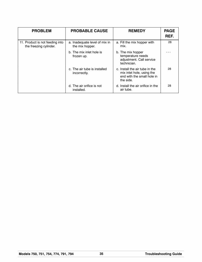
11. Product is not feeding intothe freezing cylinder.
a. Inadequate level of mix inthe mix hopper.
a. Fill the mix hopper withmix.
28
b. The mix inlet hole isfrozen up.
b. The mix hoppertemperature needsadjustment. Call servicetechnician.
- - -
c. The air tube is installedincorrectly.
c. Install the air tube in themix inlet hole, using theend with the small hole inthe side.
28
d. The air orifice is notinstalled.
d. Install the air orifice in theair tube.
28
36 Models 750, 751, 754, 774, 791, 794Parts Replacement Schedule
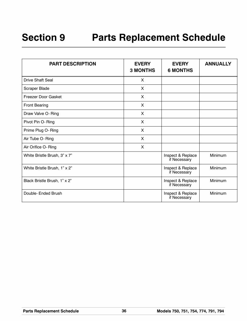
Section 9 Parts Replacement Schedule
PARTDESCRIPTION EVERY3 MONTHS
EVERY6 MONTHS
ANNUALLY
Drive Shaft Seal X
Scraper Blade X
Freezer Door Gasket X
Front Bearing X
Draw Valve O- Ring X
Pivot Pin O- Ring X
Prime Plug O- Ring X
Air Tube O- Ring X
Air Orifice O- Ring X
White Bristle Brush, 3” x 7” Inspect & Replaceif Necessary
Minimum
White Bristle Brush, 1” x 2” Inspect & Replaceif Necessary
Minimum
Black Bristle Brush, 1” x 2” Inspect & Replaceif Necessary
Minimum
Double- Ended Brush Inspect & Replaceif Necessary
Minimum
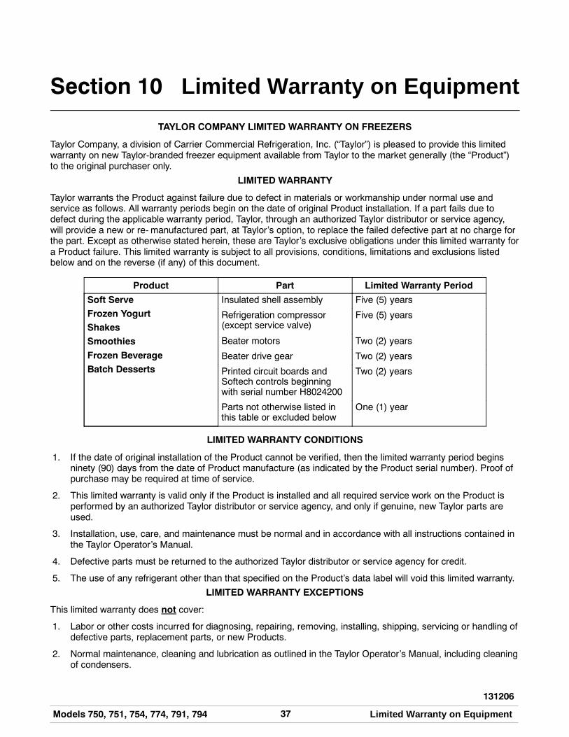
37Models 750, 751, 754, 774, 791, 794 Limited Warranty on Equipment
131206
Section 10 Limited Warranty on Equipment
TAYLOR COMPANY LIMITED WARRANTY ON FREEZERS
Taylor Company, a division of Carrier Commercial Refrigeration, Inc. (“Taylor”) is pleased to provide this limitedwarranty on new Taylor-branded freezer equipment available from Taylor to the market generally (the “Product”)to the original purchaser only.
LIMITED WARRANTY
Taylor warrants the Product against failure due to defect in materials or workmanship under normal use andservice as follows. All warranty periods begin on the date of original Product installation. If a part fails due todefect during the applicable warranty period, Taylor, through an authorized Taylor distributor or service agency,will provide a new or re- manufactured part, at Taylor’s option, to replace the failed defective part at no charge forthe part. Except as otherwise stated herein, these are Taylor’s exclusive obligations under this limited warranty fora Product failure. This limited warranty is subject to all provisions, conditions, limitations and exclusions listedbelow and on the reverse (if any) of this document.
Product Part Limited Warranty Period
Soft ServeFrozen YogurtShakesSmoothies
Frozen BeverageBatch Desserts
Insulated shell assembly Five (5) years
Refrigeration compressor(except service valve)
Five (5) years
Beater motors Two (2) years
Beater drive gear Two (2) years
Printed circuit boards andSoftech controls beginningwith serial number H8024200
Two (2) years
Parts not otherwise listed inthis table or excluded below
One (1) year
LIMITED WARRANTY CONDITIONS
1. If the date of original installation of the Product cannot be verified, then the limited warranty period beginsninety (90) days from the date of Product manufacture (as indicated by the Product serial number). Proof ofpurchase may be required at time of service.
2. This limited warranty is valid only if the Product is installed and all required service work on the Product isperformed by an authorized Taylor distributor or service agency, and only if genuine, new Taylor parts areused.
3. Installation, use, care, and maintenance must be normal and in accordance with all instructions contained inthe Taylor Operator’s Manual.
4. Defective parts must be returned to the authorized Taylor distributor or service agency for credit.
5. The use of any refrigerant other than that specified on the Product’s data label will void this limited warranty.
LIMITED WARRANTY EXCEPTIONS
This limited warranty does not cover:
1. Labor or other costs incurred for diagnosing, repairing, removing, installing, shipping, servicing or handling ofdefective parts, replacement parts, or new Products.
2. Normal maintenance, cleaning and lubrication as outlined in the Taylor Operator’s Manual, including cleaningof condensers.
38 Models 750, 751, 754, 774, 791, 794Limited Warranty on Equipment
3. Replacement of wear items designated as Class “000” parts in the Taylor Operator’s Manual.
4. External hoses, electrical power supplies, and machine grounding.
5. Parts not supplied or designated by Taylor, or damages resulting from their use.
6. Return trips or waiting time required because a service technician is prevented from beginning warrantyservice work promptly upon arrival.
7. Failure, damage or repairs due to faulty installation, misapplication, abuse, no or improper servicing,unauthorized alteration or improper operation or use as indicated in the Taylor Operator’s Manual, includingbut not limited to the failure to use proper assembly and cleaning techniques, tools, or approved cleaningsupplies.
8. Failure, damage or repairs due to theft, vandalism, wind, rain, flood, high water, water, lightning, earthquakeor any other natural disaster, fire, corrosive environments, insect or rodent infestation, or other casualty,accident or condition beyond the reasonable control of Taylor; operation above or below the electrical orwater supply specification of the Product; or components repaired or altered in any way so as, in thejudgment of the Manufacturer, to adversely affect performance, or normal wear or deterioration.
9. Any Product purchased over the Internet.
10. Failure to start due to voltage conditions, blown fuses, open circuit breakers, or damages due to theinadequacy or interruption of electrical service.
11. Electricity or fuel costs, or increases in electricity or fuel costs from any reason whatsoever.
12. Damages resulting from the use of any refrigerant other than that specified on the Product’s data label willvoid this limited warranty.
13. Any cost to replace, refill or dispose of refrigerant, including the cost of refrigerant.
14. ANY SPECIAL, INDIRECT OR CONSEQUENTIAL PROPERTY OR COMMERCIAL DAMAGE OF ANYNATURE WHATSOEVER. Some jurisdictions do not allow the exclusion of incidental or consequentialdamages, so this limitation may not apply to you.
This limited warranty gives you specific legal rights, and you may also have other rights which vary fromjurisdiction to jurisdiction.
LIMITATION OF WARRANTY
THIS LIMITED WARRANTY IS EXCLUSIVE AND IS IN LIEU OF ALL OTHER WARRANTIES, CONDITIONSAND/OR REMEDIES UNDER THE LAW, INCLUDING ANY IMPLIED WARRANTIES OR CONDITIONS OFMERCHANTABILITY OR FITNESS FOR A PARTICULAR PURPOSE. THE ORIGINAL OWNER’S SOLEREMEDY WITH RESPECT TO ANY PRODUCTS SHALL BE REPAIR OR REPLACEMENT OF DEFECTIVECOMPONENTS UNDER THE TERMS OF THIS LIMITED WARRANTY. ALL RIGHTS TO CONSEQUENTIALOR INCIDENTAL DAMAGES (INCLUDING CLAIMS FOR LOST SALES, LOST PROFITS, PRODUCT LOSS,PROPERTY DAMAGES OR SERVICE EXPENSES) ARE EXPRESSLY EXCLUDED. THE EXPRESSWARRANTIES MADE IN THIS LIMITED WARRANTY MAY NOT BE ALTERED, ENLARGED, OR CHANGEDBY ANY DISTRIBUTOR, DEALER, OR OTHER PERSON, WHATSOEVER.
LEGAL REMEDIES
The owner must notify Taylor in writing, by certified or registered letter to the following address, of any defect orcomplaint with the Product, stating the defect or complaint and a specific request for repair, replacement, or othercorrection of the Product under warranty, mailed at least thirty (30) days before pursuing any legal rights orremedies.
Taylor Companya division of Carrier Commercial Refrigeration, Inc.
750 N. Blackhawk Blvd.Rockton, IL 61072, U.S.A.
39Models 750, 751, 754, 774, 791, 794 Limited Warranty on Parts
131206
Section 11 Limited Warranty on Parts
TAYLOR COMPANY LIMITED WARRANTY ON TAYLOR GENUINE PARTS
Taylor Company, a division of Carrier Commercial Refrigeration, Inc. (“Taylor”) is pleased to provide this limitedwarranty on new Taylor genuine replacement components and parts available from Taylor to the market generally(the “Parts”) to the original purchaser only.
LIMITED WARRANTY
Taylor warrants the Parts against failure due to defect in materials or workmanship under normal use and serviceas follows. All warranty periods begin on the date of original installation of the Part in the Taylor unit. If a Part failsdue to defect during the applicable warranty period, Taylor, through an authorized Taylor distributor or serviceagency, will provide a new or re- manufactured Part, at Taylor’s option, to replace the failed defective Part at nocharge for the Part. Except as otherwise stated herein, these are Taylor’s exclusive obligations under this limitedwarranty for a Part failure. This limited warranty is subject to all provisions, conditions, limitations and exclusionslisted below and on the reverse (if any) of this document.
Part’s Warranty Class Code or Part Limited Warranty Period
Class 103 Parts¹ Three (3) months
Class 212 Parts² Twelve (12) months
Class 512 Parts Twelve (12) months
Class 000 Parts No warranty
Taylor Part #072454 (Motor- 24VDC *C832/C842*) Four (4) years
LIMITED WARRANTY CONDITIONS
1. If the date of original installation of the Part cannot be otherwise verified, proof of purchase may be requiredat time of service.
2. This limited warranty is valid only if the Part is installed and all required service work in connection with thePart is performed by an authorized Taylor distributor or service agency.
3. The limited warranty applies only to Parts remaining in use by their original owner at their original installationlocation in the unit of original installation.
4. Installation, use, care, and maintenance must be normal and in accordance with all instructions contained inthe Taylor Operator’s Manual.
5. Defective Parts must be returned to the authorized Taylor distributor or service agency for credit.
6. This warranty is not intended to shorten the length of any warranty coverage provided pursuant to a separateTaylor Limited Warranty on freezer or grill equipment.
7. The use of any refrigerant other than that specified for the unit in which the Part is installed will void thislimited warranty.
1, 2 Except that Taylor Part #032129SER2 (Compressor-Air-230V SERV) and Taylor Part #075506SER1(Compressor-Air-115V 60HZ) shall have a limited warranty period of twelve (12) months when used in Taylorfreezer equipment and a limited warranty period of two (2) years when used in Taylor grill equipment.
40 Models 750, 751, 754, 774, 791, 794Limited Warranty on Parts
LIMITED WARRANTY EXCEPTIONS
This limited warranty does not cover:
1. Labor or other costs incurred for diagnosing, repairing, removing, installing, shipping, servicing or handling ofdefective Parts, replacement Parts, or new Parts.
2. Normal maintenance, cleaning and lubrication as outlined in the Taylor Operator’s Manual, including cleaningof condensers or carbon and grease buildup.
3. Required service, whether cleaning or general repairs, to return the cooking surface assemblies, includingthe upper platen and lower plate, to an operational condition to achieve proper cooking or allow properassembly of release sheets and clips as a result of grease build-up on the cooking surfaces, including butnot limited to the platen and plate, sides of the shroud or top of the shroud.
4. Replacement of cooking surfaces, including the upper platen and lower plate, due to pitting or corrosion (orin the case of the upper platen, due to loss of plating) as a result of damage due to the impact of spatulas orother small wares used during the cooking process or as a result of the use of cleaners, cleaning materialsor cleaning processes not approved for use by Taylor.
5. Replacement of wear items designated as Class “000” Parts in the Taylor Operator’s Manual, as well as anyrelease sheets and clips for the Product’s upper platen assembly.
6. External hoses, electrical power supplies, and machine grounding.
7. Parts not supplied or designated by Taylor, or damages resulting from their use.
8. Return trips or waiting time required because a service technician is prevented from beginning warrantyservice work promptly upon arrival.
9. Failure, damage or repairs due to faulty installation, misapplication, abuse, no or improper servicing,unauthorized alteration or improper operation or use as indicated in the Taylor Operator’s Manual, includingbut not limited to the failure to use proper assembly and cleaning techniques, tools, or approved cleaningsupplies.
10. Failure, damage or repairs due to theft, vandalism, wind, rain, flood, high water, water, lightning, earthquakeor any other natural disaster, fire, corrosive environments, insect or rodent infestation, or other casualty,accident or condition beyond the reasonable control of Taylor; operation above or below the gas, electrical orwater supply specification of the unit in which a part is installed; or Parts or the units in which they areinstalled repaired or altered in any way so as, in the judgment of Taylor, to adversely affect performance, ornormal wear or deterioration.
11. Any Part purchased over the Internet.
12. Failure to start due to voltage conditions, blown fuses, open circuit breakers, or damages due to theinadequacy or interruption of electrical service.
13. Electricity, gas or other fuel costs, or increases in electricity or fuel costs from any reason whatsoever.
14. Damages resulting from the use of any refrigerant other than that specified for the unit in which the Part isinstalled will void this limited warranty.
15. Any cost to replace, refill or dispose of refrigerant, including the cost of refrigerant.
16. ANY SPECIAL, INDIRECT OR CONSEQUENTIAL PROPERTY OR COMMERCIAL DAMAGE OF ANYNATURE WHATSOEVER. Some jurisdictions do not allow the exclusion of incidental or consequentialdamages, so this limitation may not apply to you.
This limited warranty gives you specific legal rights, and you may also have other rights which vary fromjurisdiction to jurisdiction.
41Models 750, 751, 754, 774, 791, 794 Limited Warranty on Parts
LIMITATION OF WARRANTY
THIS LIMITED WARRANTY IS EXCLUSIVE AND IS IN LIEU OF ALL OTHER WARRANTIES, CONDITIONSAND/OR REMEDIES UNDER THE LAW, INCLUDING ANY IMPLIED WARRANTIES OR CONDITIONS OFMERCHANTABILITY OR FITNESS FOR A PARTICULAR PURPOSE. THE ORIGINAL OWNER’S SOLEREMEDY WITH RESPECT TO ANY PRODUCTS SHALL BE REPAIR OR REPLACEMENT OF DEFECTIVEPARTS UNDER THE TERMS OF THIS LIMITED WARRANTY. ALL RIGHTS TO CONSEQUENTIAL ORINCIDENTAL DAMAGES (INCLUDING CLAIMS FOR LOST SALES, LOST PROFITS, PRODUCT LOSS,PROPERTY DAMAGES OR SERVICE EXPENSES) ARE EXPRESSLY EXCLUDED. THE EXPRESSWARRANTIES MADE IN THIS LIMITED WARRANTY MAY NOT BE ALTERED, ENLARGED, OR CHANGEDBY ANY DISTRIBUTOR, DEALER, OR OTHER PERSON, WHATSOEVER.
LEGAL REMEDIES
The owner must notify Taylor in writing, by certified or registered letter to the following address, of any defect orcomplaint with the Part, stating the defect or complaint and a specific request for repair, replacement, or othercorrection of the Part under warranty, mailed at least thirty (30) days before pursuing any legal rights or remedies.
Taylor Companya division of Carrier Commercial Refrigeration, Inc.
750 N. Blackhawk Blvd.Rockton, IL 61072, U.S.A.