Embed Size (px)
Citation preview

OPERATOR’S MANUAL26 Gallon Portable Air CompressorF2S26VWDVP / 671-049
Your air compressor has been engineered and manufactured to Husky’s high standard for dependability, ease of operation, and operator safety. When properly cared for, it will give you years of rugged, trouble-free performance.
Thank you for buying a Husky product.
SAVE THIS MANUAL FOR FUTURE REFERENCE
WARNING: To reduce the risk of injury, the user must read and understand the operator’s manual before using this product.
02/09/2009
This tool has many features for making its use more pleasant and enjoyable. Safety, performance, and dependability have been given top priority in the design of this product making it easy to maintain and operate.
CAUTION This compressor is intended to be used at a duty cycle 50%.
DANGER
This compressor/pump is not equipped and should not be used to supply breathing quality air. Additional equipment wouldbenecessarytoproperlyfilterandpurifytheairtomeetminimalspecificationsforGradeDbreathingasdescribed inCompressedGasAssociationCommoditySpecificationG7.1 - 1966,OSHA29CFR1910.134.CompressedGas Association, 4221Walney Road, Fifth Floor, Chantilly, VA 20151-2923, (703) 788-2700, www.cganet.com.Any such additional equipment has not been examined and no implication of proper use for breathing air is intended or implied. If this compressor is altered in any way, existing warranties shall be voided. Husky and MAT Holdings, Inc. disclaim any liabilities whatsoever for any loss, personal injury, or damage.
TABLE OF CONTENTS
g GeneralSafetyRules . . . . . . . . . . . . . . . . . . . . . . . . . . . . . . . . . . . . . . . . . . . . . . . . . . . . . . . . . . . . .1-2g SpecificSafetyRules. . . . . . . . . . . . . . . . . . . . . . . . . . . . . . . . . . . . . . . . . . . . . . . . . . . . . . . . . . . . . . . 3g Symbols . . . . . . . . . . . . . . . . . . . . . . . . . . . . . . . . . . . . . . . . . . . . . . . . . . . . . . . . . . . . . . . . . . . . . . . .4-5g Electrical . . . . . . . . . . . . . . . . . . . . . . . . . . . . . . . . . . . . . . . . . . . . . . . . . . . . . . . . . . . . . . . . . . . . . . . . 6g GlossaryofTerms . . . . . . . . . . . . . . . . . . . . . . . . . . . . . . . . . . . . . . . . . . . . . . . . . . . . . . . . . . . . . . . . . 7g Features. . . . . . . . . . . . . . . . . . . . . . . . . . . . . . . . . . . . . . . . . . . . . . . . . . . . . . . . . . . . . . . . . . . . . . . .8-9g Assembly . . . . . . . . . . . . . . . . . . . . . . . . . . . . . . . . . . . . . . . . . . . . . . . . . . . . . . . . . . . . . . . . . . . . . . . . 9g Operation . . . . . . . . . . . . . . . . . . . . . . . . . . . . . . . . . . . . . . . . . . . . . . . . . . . . . . . . . . . . . . . . . . . . .10-13g Maintenance . . . . . . . . . . . . . . . . . . . . . . . . . . . . . . . . . . . . . . . . . . . . . . . . . . . . . . . . . . . . . . . . . . . . 14g Pneumatic Tool Usage. . . . . . . . . . . . . . . . . . . . . . . . . . . . . . . . . . . . . . . . . . . . . . . . . . . . . . . . . . . . . 15g Troubleshooting . . . . . . . . . . . . . . . . . . . . . . . . . . . . . . . . . . . . . . . . . . . . . . . . . . . . . . . . . . . . . . . . . . 16g ExplodedView . . . . . . . . . . . . . . . . . . . . . . . . . . . . . . . . . . . . . . . . . . . . . . . . . . . . . . . . . . . . . . . . . . . 17g Parts List . . . . . . . . . . . . . . . . . . . . . . . . . . . . . . . . . . . . . . . . . . . . . . . . . . . . . . . . . . . . . . . . . . . . . . . 18g Warranty . . . . . . . . . . . . . . . . . . . . . . . . . . . . . . . . . . . . . . . . . . . . . . . . . . . . . . . . . . . . . . . . . . . . . . . 19g Notes . . . . . . . . . . . . . . . . . . . . . . . . . . . . . . . . . . . . . . . . . . . . . . . . . . . . . . . . . . . . . . . . . . . . . . . . . . 20
INTRODUCTION

WARNING Readandunderstandallinstructions.Failuretofollowallinstructionslistedbelowmayresultinelectricshock,fire,and/or serious personal injury.
SAVE THESE INSTRUCTIONS
WORK AREA
g Keep your work area clean and well lit. Cluttered benchesanddarkareasinviteaccidents.Floormustnotbe slippery from wax or dust.
gDo not operate power tools in explosive atmospheres, such as in the presence of flammable liquids, gases, or dust. Power tools create sparks which may ignite the dust or fumes.
g Keep bystanders, children, and visitors away while operating tools.Distractions can cause you to lose control.
g Operate air compressor in an open area at least 18 in. away from any wall or object that could restrict the flow of fresh air to ventilation openings.
ELECTRICAL SAFETY
g Avoid body contact with grounded surfaces such as pipes, radiators, ranges, and refrigerators. There is an increased risk of electric shock if your body is grounded.
g Don’t expose power tools to rain or wet conditions. Water entering a power tool will increase the risk of electric shock.
g Do not abuse the cord. Never use the cord to carry the tool or pull the plug from an outlet. Keep cord away from heat, oil, sharp edges, or moving parts. Replace damaged cords immediately. Damaged cords increase the risk of electric shock.
g When operating a power tool outside, use an outdoor extension cord marked “W-A” or “W”. These cords are rated for outdoor use and reduce the risk of electric shock.
PERSONAL SAFETY
g Eye protection which conforms to ANSI specifications and provides protection against flying particles both from the FRONT and SIDE should ALWAYS be worn by the operator and others in the work area when loading, operating, or servicing this tool. Eye protection is requiredtoguardagainstflyingfastenersanddebris,which could cause severe eye injury.
g The employer and/or user must ensure that proper eye protection is worn.WerecommendaWideVisionSafety Mask for use over eyeglasses or standard safety glasses thatprovideprotectionagainstflyingparticlesbothfromthe front and side. Always use eye protection which is marked tocomplywithANSIZ87.1.
g Additional safety protection will be required in some environments.Forexample,theworkingareamayinclude exposure to a noise level which can lead to hearing damage. The employer and user must ensure that any necessary hearing protection is provided and used by the operator and others in the work area. Some environments will require the use of head protection equipment. When required, the employer and user must ensure that head protectionmarkedtocomplywithANSIZ89.1isused.
g Stay alert, watch what you are doing, and use common sense when operating a power tool. Do not use tool while tired or under the influence of drugs, alcohol, or medication. A moment of inattention while operating power tools may result in serious personal injury.
g Dress properly. Do not wear loose clothing or jewelry. Contain long hair. Keep your hair, clothing, and gloves away from moving parts. Loose clothes, jewelry, or long hair can be caught in moving parts.
g Do not overreach. Keep proper footing and balance at all times. Proper footing and balance enables better control of the tool in unexpected situations.
g Use safety equipment. Always wear eye protection. Dustmask,nonskidsafetyshoes,hardhat,orhearing protection must be used for appropriate conditions.
g Do not use on a ladder or unstable support. Stable footing on a solid surface enables better control of the tool in unexpected situations.
TOOL USE AND CARE
g Do not exceed the pressure rating of any component in the system.
g Protect material lines and air lines from damage or puncture. Keep hose and power cord away from sharp objects,chemicalspills,oil,solvents,andwetfloors.
g Check hoses for weak or worn condition before each use, making certain all connections are secure.Donot use if defect is found. Purchase a new hose or notify an authorized service center for examination or repair.
g Release all pressures within the system slowly.Dust and debris may be harmful.
g Store idle tools out of the reach of children and other untrained persons. Tools are dangerous in the hands of untrained users.
Page 1
GENERAL SAFETY RULES

g Maintain tools with care.Followmaintenanceinstructions. Properly maintained tools are easier to control.
g Check for misalignment or binding of moving parts, breakage of parts, and any other condition that may affect the tool’s operation. If damaged, have the tool serviced before using. Many accidents are caused by poorly maintained tools.
g Never point any tool toward yourself or others.
g Keep the exterior of the air compressor dry, clean, and free from oil and grease. Always use a clean cloth when cleaning. Never use brake fluids, gasoline, petroleum- based products, or any strong solvents to clean the unit. Followingthisrulewillreducetheriskofdeteriorationofthe enclosure plastic.
SERVICE
g Tool service must be performed only by qualified repair personnel. Service or maintenance performed by unqualifiedpersonnelmayresultinariskofinjury.
g Disconnect power supply, open drain valve to decompress tank and allow water to drain, and allow air compressor to become cool to the touch before servicing. Turn pressure regulator knob fully c l o c k w i s e after shutting off compressor.
g When servicing a tool, use only identical replacement parts. Follow instructions in the Maintenance section of this manual. Use of unauthorized parts or failure to follow Maintenance instructions may create a risk of injury.
Page 2
GENERAL SAFETY RULES

g Know your power tool.Readoperator’smanualcarefully. Learnitsapplicationsandlimitations,aswellasthespecific potentialhazardsrelated to this tool.Following this rulewill reducetheriskofelectricshock,fire,orseriousinjury.
g Drain tank of moisture after each day’s use. If unit will not be used for a while, it is best to leave drain valve open until such time as it is to be used. This will allow moisture to completely drain out and help prevent corrosion on the inside of tank.
g Risk of Fire or Explosion.Onlysprayflammable liquids suchaspaintsorlacquers.Neversprayflammableliquids inaconfinedarea.Sprayareamustbewellventilated.Do notsmokewhilesprayingorspraywheresparkorflameis present. Keep compressors as far from the spraying area aspossible,atleast15feetfromthesprayingareaandall explosive vapors.
g Risk of Bursting.Donotadjustregulatortoresultinoutput pressure greater than marked maximum pressure of attachment. Do not use a pressure greater thanmaximum rated pressure of compressor.
g If connected to a circuit protected by fuses, use time- delay fuses with this product.
g To reduce the risk of electric shock, do not expose to rain. Store indoors.
g Inspect tank yearly for rust, pin holes, or other imperfections that could cause it to become unsafe. Never weld or drill holes in the air tank.
g Make sure the hose is free of obstructions or snags. Entangled or snarled hoses can cause loss of balance or footing and may become damaged.
g Use the air compressor only for its intended use. Do not alter or modify the unit from the original design or function.
gAlways be aware that misuse and improper handling of this tool can cause injury to yourself and others.
gNever leave a tool unattended with the air hose attached.
gDo not operate this tool if it does not contain a legible warning label.
gDo not continue to use a tool or hose that leaks air or does not function properly.
g Always disconnect the air supply and power supply before making adjustments, servicing a tool, or when a tool is not in use.
gDo not attempt to pull or carry the air compressor by the hose.
g Your tool may require more air consumption than this air compressor is capable of providing.
g Never store tool with air connected. Storing the tool with airconnectedcanresultinunexpectedfiringandpossible serious personal injury.
gAlways follow all safety rules recommended by the manufacturer of your air tool, in addition to all safety rules for the air compressor. Following this rule will reduce the risk of serious personal injury.
gNever direct a jet of compressed air toward people or animals. Take care not to blow dust and dirt towards yourself or others. Followingthisrulewillreducetherisk of serious injury.
gProtect your lungs. Wear a face or dust mask if the operation isdusty.Following this rulewill reduce the risk of serious personal injury.
g Do not use this air compressor to spray chemicals. Your lungs can be damaged by inhaling toxic fumes. A respirator may be necessary in dusty environments or when sprayingpaint.Donotcarrywhilepainting.
g Inspect tool cords and hoses periodically and, if damaged, have repaired at your nearest Authorized Service Center. Constantly stay aware of cord location.Followingthisrulewillreducetheriskofelectric shockorfire.
g Never use an electrical adaptor with this grounded plug.
g Check damaged parts. Before further use of the air compressor or air tool, a guard or other part that is damaged should be carefully checked to determine that it will operate properly and perform its intended function. Check for alignment of moving parts, binding of moving parts, breakage of parts, mounting, and any other conditions that may affect its operation. A guard or other part that is damaged should be properly repaired or replaced by an authorized service center. Following this rule will reducetheriskofshock,fire,orseriousinjury.
g Make sure your extension cord is in good condition. When using an extension cord, be sure to use one heavy enough to carry the current your product will draw. A wire gauge size (A.W.G.) of at least 14 is recommended for an extension cord 50 feet or less in length. A cord exceeding 100 feet is not recommended. If in doubt, use the next heavier gauge. The smaller the gauge number, the heavier the cord. An undersized cord will cause a drop in line voltage resulting in loss of power and overheating.
g Save these instructions.Refertothemfrequentlyanduse them to instruct others who may use this air compressor. If you loan someone this tool, loan them these instructions also.
Page 3
SPECIFIC SAFETY RULES

Page 4
Some of the following symbols may be used on this tool. Please study them and learn their meaning. Proper interpretation of these symbols will allow you to operate the tool better and safer.
SYMBOLS
SYMBOL NAME DESIGNATION/EXPLANATION
V Volts VoltageA Amperes Current
Hz Hertz Frequenct(cyclespersecond)Alternating Current Type of currentClass II Construction Double-insulatedconstructon
Wet Conditions Alert Donotexposetorainoruseindamplocations.
ReadTheOperator’sManual To reduce the risk of injury, user must read and understand operator’s manual before using this product.
Eye Protection Always wear safety goggles or safety glasses with side shields and, as necessary, a full face shield when operating this product.
Safety Alert Precautions that involve your safety.
RiskofBursting Donotadjustregulatortoresultinoutputpressuregreaterthanmarked maximum pressure of attachment. Donotuseapres-sure greater than maximum rated pressure of compressor.
RiskofFireorExplosion Donotsprayflammableliquidinaconfinedarea.Sprayareamustbewellventilated.Donotsmokewhilesprayingorspraywheresparkorflameispresent.Keepcompressorsasfarfromthesprayingareaaspossible,atleast15feetfromthesprayingarea and all explosive vapors.
RiskofElectricalShock HazardousVoltage:Disconnectfrompowersourcebeforeser-vicing.Compressor must be grounded.
Hot Surface To reduce the risk of injury or damage, avoid contact with any hot surface.
RisktoBreathing Air obtained directly from the air compressor should never be used to supply air for human consumption.

Page 5
SYMBOLS
The following signal words and meanings are intended to explain the levels of risk associated with this product.SYMBOL SIGNAL MEANING
DANGER Indicates an imminently hazardous situation, which, if not avoided, will result in death or serious injury.
WARNING Indicates a potentially hazardous situation, which, if not avoided, could result in death or serious injury.
CAUTION Indicates a potentially hazardous situation, which, if not avoided, may result in minor or moderate injury.
CAUTION (WithoutSafetyAlertSymbol)Indicatesasituationthatmayresultinpropertydamage.
SERVICEServicing requires extreme care and knowledge and should be performedonlybyaqualifiedservicetechnician.Forservicewesuggest you return the product to the nearest AUTHORIZED SERVICE CENTER for repair. When servicing, use only identical replacement parts.
WARNING
To avoid serious personal injury, do not attempt to use this product until you read thoroughly and understand completely the operator’s manual. If you do not understand the warnings and instructions in the operator’s manual, do not use this product. Call customer service for assistance.
The operation of any power tool can result in foreign objects being thrown into your eyes, which can result in severe eye damage.Before beginning power tool operation, alwayswear safety goggles orsafetyglasseswithsideshieldsand,whenneeded,afullfaceshield.WerecommendWideVisionSafetyMask for use over eyeglasses or standard safety glasses with side shields. Always use eye protection whichismarkedtocomplywithANSIZ87.1.
WARNING
SAVE THESE INSTRUCTIONS

EXTENSION CORDSUseonly3-wireextensioncordsthathave3-pronggroundingplugsand3-pole receptacles thataccept theproduct’splug.When using a power tool at a considerable distance from the power source, use an extension cord heavy enough to carry the current that the product will draw. An undersized exten-sion cord will cause a drop in line voltage, resulting in a loss of power and causing the motor to overheat. Use the chart provided below to determine the minimum wire size required in an extension cord.Only round jacketed cords listed by Underwriter’sLaboratories(UL)shouldbeused.
When working with the product outdoors, use an extension cord that is designed for outside use. This is indicated by the letters “WA” on the cord’s jacket.
Beforeusinganextensioncord,inspectitforlooseorexposedwires and cut or worn insulation.
WARNING
Keep the extension cord clear of the working area. Position the cord so that it will not get caught on lumber, tools, or other obstructions while you are working with a powertool.Failuretodosocanresultinseriouspersonal injury.
WARNING
Check extension cords before each use. If damaged replace immediately. Never use the product with a damaged cord since touching the damaged area could cause electrical shock resulting in serious injury.
ELECTRICAL CONNECTIONThis product is powered by a precision-built electric motor. It should be connected to a power supply that is 120 volts, 60 Hz, AC only (normal household current). Do not operatethisproductondirectcurrent(DC).Asubstantialvoltagedropwill cause a loss of power and the motor will overheat. If the product does not operate when plugged into an outlet, double check the power supply.
SPEED AND WIRINGTheno-loadspeedofthisproductisapproximately3,450rpm.This speed is not constant and decreases under a load or with lowervoltage.Forvoltage, thewiring inashop isas impor-tant as the motor’s horsepower rating. A line intended only for lights cannot properly carry a power tool motor. Wire that is heavy enough for a short distance will be too light for a greater distance. A line that can support one power tool may not be able to support two or three products.
GROUNDING INSTRUCTIONSThis product must be grounded. In the event of a malfunction or breakdown, grounding provides a path of least resistance for electric current to reduce the risk of electric shock. This product is equipped with an electric cord having an equipment-grounding conductor and a grounding plug. The plug must be plugged into a matching outlet that is properly installed and grounded in accordance with all local codes and ordinances.
Donotmodifytheplugprovided.Ifitwillnotfittheoutlet,havetheproperoutletinstalledbyaqualifiedelectrician.Improperconnection of the equipment-grounding conductor can result in a risk of electric shock. The conductor with insulation having an outer surface that is green with or without yellow stripes is the equipment-grounding conductor. If repair or replacement of the electric cord or plug is necessary, do not connect the equipment-groundingconductortoeitherflatbladeterminal(aliveterminal).
Checkwithaqualifiedelectricianorservicepersonnel if thegrounding instructions are not completely understood, or if in doubtastowhethertheproductisproperlygrounded.Repairor replace a damaged or worn cord immediately.
This product is intended for use on a circuit that has an outlet liketheoneshowninFigure1.Italsohasagroundingpinliketheoneshown.Onlyconnecttheproducttoanoutlethaving the same configuration as the plug. Do not use anadapter with this product.
Figure1
Page 6
ELECTRICAL
**Ampererating(onproductdataplate)0 - 2.0 2.1-3.4 3.5-5.0 5.1-7.0 7.1-12.0 12.1-16.0
Cord Length Wire Size (A.W.G.)
25´ 16 16 16 16 14 1450´ 16 16 16 14 14 12100´ 16 16 14 12 10 —
**Usedon12gauge-20ampcircuit.NOTE:AWG=AmericanWireGauge
GROUNDING PIN120V GROUNDED OUTLET
Page 7
GLOSSARY OF TERMS
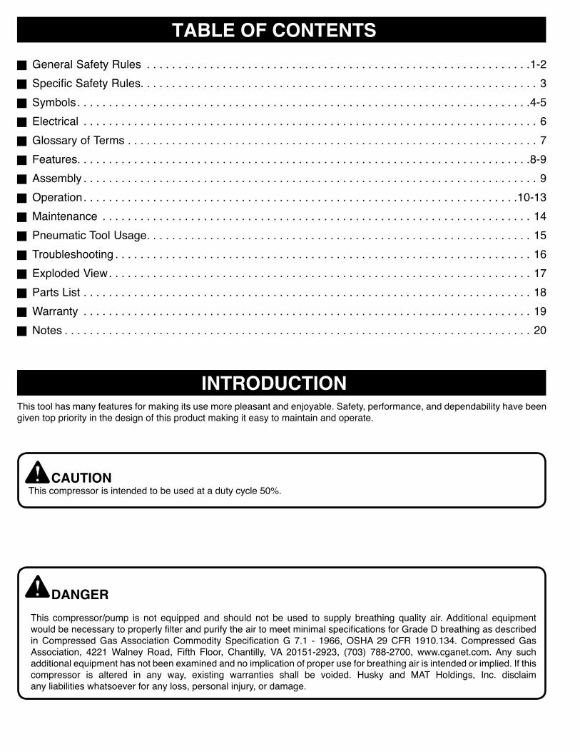
Air FilterPorous element contained within a metal or plastic housing attached to the compressor cylinder head which removes impurities from the intake air of the compressor.
Air TankCylindrical component which contains the compressed air.
Check ValveDevicethatpreventscompressedair fromflowingbackfromthe air tank to the compressor pump.
Cut-In PressureThe low pressure at which the motor will automatically restart.
Cut-Off PressureThe high pressure at which the motor will automatically shut off.
Electric MotorDevicewhichprovidestherotationalforcenecessarytooperatethe compressor pump.
Manual On/Off SwitchControl which turns the air compressor on or off. The pressure switch will not automatically start and control the compressor unlessthemanualOn/OffSwitchisintheON position.
NPT (National Pipe Thread)A seal thread tape must be used to provide a leak-free seal on pipe threaded connections.
Pressure Regulator KnobRegulatestheoutgoingpressurefromtheairoutlettothetool.It is possible to increase or decrease the pressure at the outlet by adjusting this control knob.
Pressure SwitchAutomatically controls the on/off cycling of the compressor. It stops the compressor when the cut-off pressure in the tank is reached and starts the compressor when the air pressure drops below the cut-in pressure.
PSI (Pounds Per Square Inch)Measurement of the pressure exerted by the force of the air. The actual psi is measured by a pressure gauge on the compressor.
PumpProduces the compressed air with a reciprocating piston contained within the cylinder.
Regulator Pressure GaugeDisplaysthecurrent linepressure.Linepressure isadjustedby rotating the pressure regulator knob.
Pressure Relief ValvePrevents air pressure in the air tank from rising over a predetermined limit.
SCFM (Standard Cubic Feet Per Minute)A unit of measure of air delivery.
Tank Pressure GaugeIndicates the pressure in the air tank.
Thermal Overload SwitchAutomatically shuts off the compressor if the temperature of the electric motor exceeds a predetermined limit.

Page 8
FEATURES
PRODUCT SPECIFICATIONSRunningHorsepower .....................................................1.5HPAir Tank Capacity ...........................................................26gal.Air Pressure ........................................................ 150psimax.AirDelivery ............................................... 4.0SCFM@90psi
5.0SCFM@40psi
Lubrication ...................................................................Oil-FreeGauges ...............................................................2 in. diameterInput................................... 120V,60Hz,ACOnly,15.0AmpsNet Weight .................................................................111.0lbs.
Figure2
PRESSURE REGULATOR GAUGE TANK PRESSURE
GAUGE
PRESSURE REGULATOR KNOB
ON / OFF
PRESSURE RELIEF VALVE
HANDLE MOTOR
Page 9
FEATURES
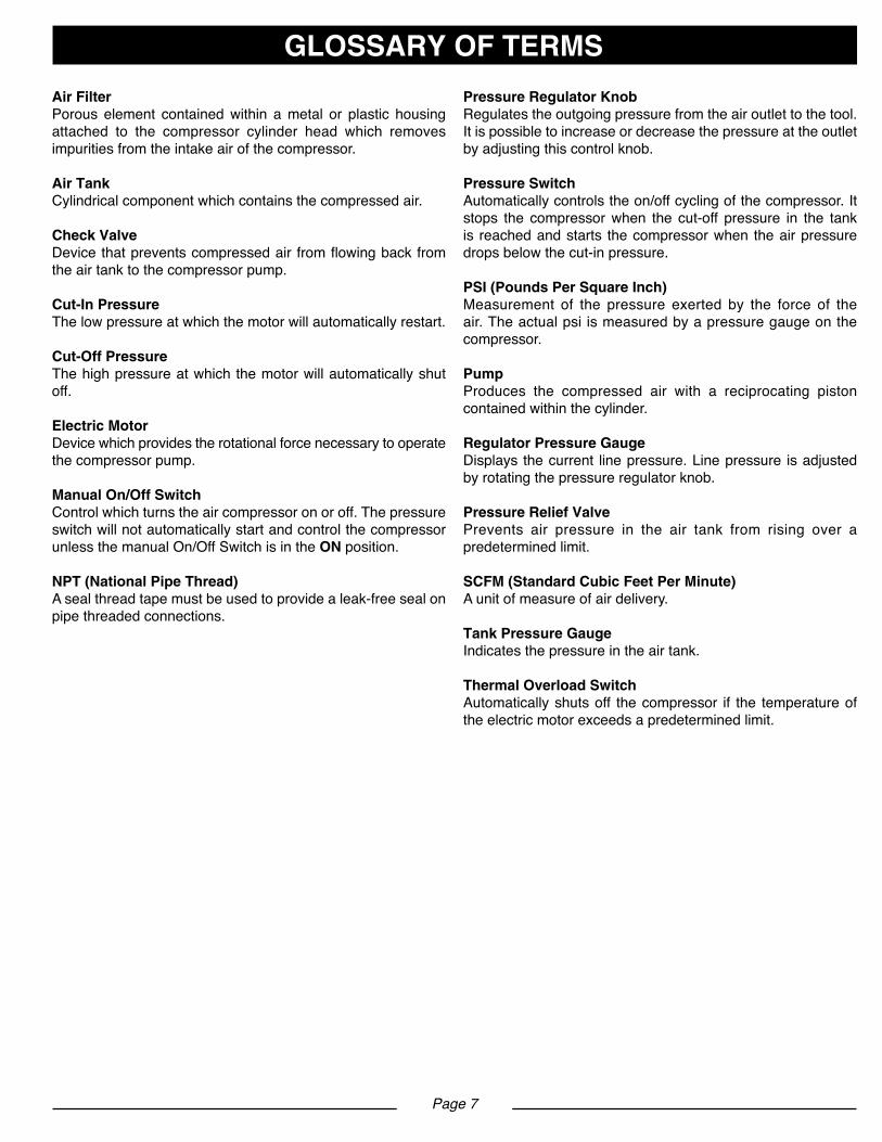
HANDLEThe air compressor is equipped with a padded carrying handle for ease of use.
OIL-FREE INDUCTION MOTORYour air compressor features permanently lubricated bearings.
PRESSURE REGULATOR KNOBUse the pressure regulator knob to adjust the amount of air being delivered through the hose.
PRESSURE RELIEF VALVEThe pressure relief valve is designed to automatically release air if the air receiver pressure exceeds the preset maximum.
REGULATOR PRESSURE GAUGEThe current line pressure is displayed on the regulator pressure gauge. This pressure can be adjusted by rotating the pressure regulator knob.
TANK PRESSURE GAUGEThe tank pressure gauge indicates the pressure of the air in the tank.
ASSEMBLYATTACHING HOSESee Figure 3.
g Make sure the air compressor is off and unplugged. Setupinstructions: 1. Compressorisassembledatfactoryandreadyfor use. Check all components to ensure secure assembly, ie., rubber feet, wheels, handle, quick connects, gages, safetyvalve,airfilter,drainvalve,etc. 2. Apply thread tape to threaded connections of hose,attach quick coupler to hose with a wrench (wrench is not provided). 3.Apply thread tape to threaded connections of male plug,attachmaleplugtohosewithawrench(wrenchis notprovided).
gRotatepressureregulatorknobfullycounterclockwise.
g Insert hose adapter end of air hose into female coupler end in air compressor.
FEMALE COUPLER
HOSE ADAPTER END
PRESSURE REGULATOR KNOB OFF
Figure3
KNOW YOUR AIR COMPRESSORSee Figure 2.The safe use of this product requires an understanding of the information on the product and in this operator’s manual as well asaknowledgeoftheprojectyouareattempting.Beforeuseofthisproduct,familiarizeyourselfwithalloperatingfeaturesandsafety rules.
Page 10
OPERATION
WARNING If any parts are damaged or missing do not operate this productuntilthepartsarereplaced.Failuretoheedthis warning could result in serious personal injury.
WARNING Do not attempt to modify this product or create accessories not recommended for use with this product. Anysuchalterationormodificationismisuseandcould result in a hazardous condition leading to possible serious personal injury.
WARNING
Donotattachairchuckorothertooltotheopenendof the hose until start-up has been completed.
WARNING Do not allow familiarity with products to make you careless.Rememberthatacarelessfractionofasecond issufficienttoinflictseriousinjury.
WARNING
Always wear safety goggles or safety glasses with side shields when operating power tools. Failure to do so could result in objects being thrown into your eyes resulting in possible serious injury.
WARNING Do not use any attachments or accessories not recommended by the manufacturer of this product. The use of attachments or accessories not recommended can result in serious personal injury.
CAUTIONDonotuseinanenvironmentthatisdustyorotherwise contaminated. Using the air compressor in this type of environment may cause damage to the unit.
UNPACKING
g Carefully remove the product from the box. Make sure that all items listed in the packing list are included.
g Inspect the product carefully to make sure no breakage or damage occurred during shipping.
gDonotdiscardthepackingmaterialuntilyouhavecarfullyinspectedandsatisfactorilyoperatedtheproduct.
gIfanypartsaredamagedormissing,pleasecall1-888-859-4549forassistance. PACKING LIST
(1)Aircompressor(1)Instructionmanual(1)Airhose(1)Threadtape(1)1/4”NPTmaleplugs(1)1/4”NPTquickcoupler(1)1/2”Impactwrench(1)3/8”Ratchet
APPLICATIONSAir compressors are utilized in a variety of air system applications. Match hoses, connectors, air tools, and accessories to the capabilities of the air compressor.
You may use this tool for the purposes listed below:
gOperatingsomelightdutyairpoweredtools.
gInflatingtires,airbeds,sportsequipment,etc. (Inflationaccessoriessoldseparately)
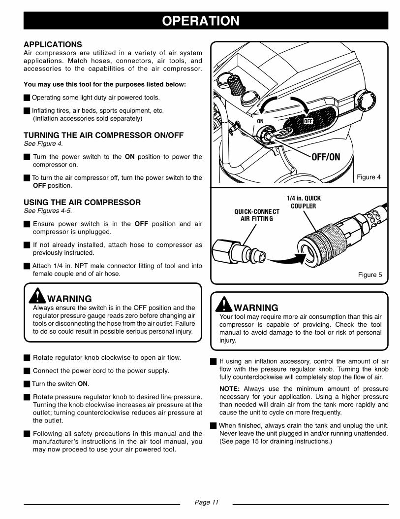
TURNING THE AIR COMPRESSOR ON/OFFSee Figure 4.
g Turn the power switch to the ON position to power the compressor on.
g To turn the air compressor off, turn the power switch to the OFF position.
USING THE AIR COMPRESSORSee Figures 4-5.
g Ensure power switch is in the OFF position and air compressor is unplugged.
g If not already installed, attach hose to compressor as previously instructed.
gAttach1/4 in.NPTmaleconnectorfittingof tooland into female couple end of air hose.
WARNINGAlwaysensuretheswitchisintheOFFpositionandthe regulator pressure gauge reads zero before changing air toolsordisconnectingthehosefromtheairoutlet.Failure to do so could result in possible serious personal injury.
gRotateregulatorknobclockwisetoopenairflow.
g Connect the power cord to the power supply.
g Turn the switch ON.
gRotatepressureregulatorknobtodesiredlinepressure. Turning the knob clockwise increases air pressure at the outlet; turning counterclockwise reduces air pressure at the outlet.
gFollowingallsafetyprecautions inthismanualandthe manufacturer’s instructions in the air tool manual, you may now proceed to use your air powered tool.
WARNING Your tool may require more air consumption than this air compressor is capable of providing. Check the tool manual to avoid damage to the tool or risk of personal injury.
gIf using an inflation accessory, control the amount of air flow with the pressure regulator knob. Turning the knob fullycounterclockwisewillcompletelystoptheflowofair.
NOTE: Always use the minimum amount of pressure necessary for your application. Using a higher pressure than needed will drain air from the tank more rapidly and cause the unit to cycle on more frequently.
gWhenfinished,alwaysdrainthetankandunplugtheunit. Never leave the unit plugged in and/or running unattended. (Seepage15fordraininginstructions.)
Page 11
OPERATION
QUICK-CONNE CT AIR FITTING
1/4 in. QUICK COU PLER
Figure4
Figure5
OFF/ON
OFFON
Page 12
OPERATION
WARNINGAlways disconnect the air supply and power supply beforemakingadjustments,servicingatool,orwhenatoolisnotinuse.
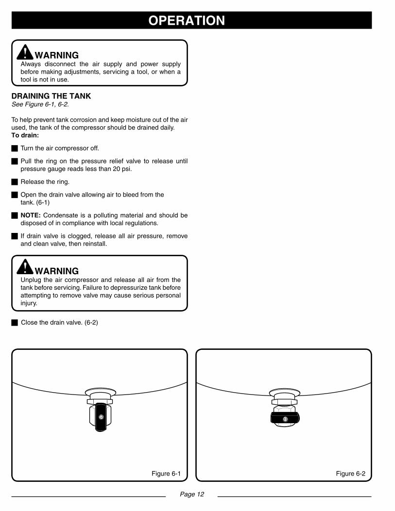
DRAINING THE TANKSee Figure 6-1, 6-2.
Tohelppreventtankcorrosionandkeepmoistureoutoftheairused,thetankofthecompressorshouldbedraineddaily.To drain:
gTurntheaircompressoroff.
gPull the ring on the pressure relief valve to release until pressuregaugereadslessthan20psi.
gReleasethering.
gOpenthedrainvalveallowingairtobleedfromthe tank.(6-1)
gNOTE:Condensate isapollutingmaterialandshouldbe disposedofincompliancewithlocalregulations.
gIfdrainvalve isclogged, releaseallairpressure, remove andcleanvalve,thenreinstall.
WARNINGUnplug theaircompressorandreleaseallair fromthe tankbeforeservicing.Failuretodepressurizetankbeforeattemptingtoremovevalvemaycauseseriouspersonal injury.
gClosethedrainvalve.(6-2)
Figure6-2Figure6-1

CHECKING THE PRESSURE RELIEF VALVESee Figure 7-8.
DANGER Donotattempttotamperwiththepressurereliefvalve. Anythingloosenedfromthisdevicecouldflyupandhit you.Failuretoheedthiswarningcouldresultindeathor serious personal injury.
The pressure relief valve will automatically release air if the air receiver pressure exceeds the preset maximum. The valve should be checked before each day of use by pulling the ring by hand.
gTurntheaircompressoronandallowthetanktofill.The compressor will shut off when the pressure reaches the preset maximum.
g Turn the air compressor off.
g Pull the ring on the pressure relief valve to release air for threetofiveseconds.
gReleasethering.Airmustimmediatelystopescaping when the ring is released. Any continued loss of air after releasing the ring indicates a problem with the pressure relief valve. Discontinue use and seek service before continued use of the air compressor.
WARNING If air leaks after the ring has been released, or if the valve is stuck and cannot be actuated by the ring, do not use the air compressor until the pressure relief valve has been replaced. Use of the air compressor in this condition could result in serious personal injury.
THERMAL OVERLOAD PROTECTIONThis compressor is equipped with a thermal overload protector which will shut off motor if it becomes overheated.IfoverloadprotectorshutsmotorOFFfrequently,lookforthefollowing causes.Low voltageLack of proper ventilation/room temperature too highWrong gauge wire or length of extension cordTo reset the air compressor:
g Turn the air compressor off.
g Unplug air compressor and wait until compressor cools down.
g Plug the air compressor into an approved outlet.
g Turn the air compressor on.
Page 13
OPERATION
Figure7PRESSURE RELIEF
VALVE
PRESSURE RELIEF VALVE
RING
TO RELEASE AIR
Figure8

Page 14
MAINTENANCE
WARNING
When servicing, use only identical Husky replacement parts. Use of any other parts may create a hazard or cause product damage.
WARNING Do not attempt to modify this product or create Always wear safety goggles or safety glasses with side shields during power tool operation or when blowing dust. If operation is dusty, also wear a dust mask.
WARNING Always release all pressure, disconnect from power supply, and allow unit to cool to the touch before cleaning or making repairs on the air compressor.
GENERAL MAINTENANCEHumidity in the air causes condensate to form in the air tank. This condensate should be drained daily and/or every hour, using the instructions found in Draining the Tank.The pressure relief valve automatically releases air if the air receiver pressure exceeds the preset maximum. Check the pressure relief valve before each use following the instructions found in Checking the Pressure Relief Valve.Inspect the tank yearly for rust, pin holes, or other imperfections that could cause it to become unsafe.Avoid using solvents when cleaning plastic parts. Most plastics are susceptible to damage from various types of commercial solvents and may be damaged by their use. Use clean cloths to remove dirt, dust, oil, grease, etc. WARNING Donotatanytimeletbrakefluids,gasoline,petroleum- based products, penetrating oils, etc., come in contact with plastic parts. Chemicals can damage, weaken or destroy plastic which may result in serious personal injury.Electrictoolsusedonfiberglassmaterial,wallboard, spackling compounds, or plaster are subject to accelerated wearandpossibleprematurefailurebecausethefiberglass chips and grindings are highly abrasive to bearings, brushes, commutators, etc. Consequently, we do not recommended using this tool for extended work on these types of materials. However, if you do work with any of these materials, it is extremely important to clean the tool using compressed air.
LUBRICATIONAllof thebearings in this toolare lubricatedwithasufficientamount of high grade lubricant for the life of the unit under normal operating conditions. Therefore, no further lubrication of the bearings is required.
CLEANING THE AIR FILTERSee Figure 9.
From time to time, theair filter needs tobe removedandcleaned.
g Turn the air compressor off.
g Unplug the air compressor.
g Turntheairfitercovercounterclockwisetoremove.
g Removeairfilterfromairfilterhousing.
g Blowcompressedairthroughtheairfilterfor10-15seconds.
STORAGE1.Draintankofmoisture.
2. When not in use, store compressor in a cool, dry place.
3.Disconnecthoseandhangopenendsdowntoallowany moisture to drain.
4. Wrap the power cord on handle
Figure9

ASSEMBLY OF AIR TOOLApplythreadtapetothreadedconnectionsof1/4”NPTmaleplug,attachmaleplugtohosewithawrench(wrenchand1/4”NPTmaleplugarenotprovided).Ensure regulator of compressor is adjusted to minimum posi-tion if a compressor is used and ensure outlet pressure is near zero.Attach1/4”NPTmaleplugoftooltofemalecoupleendofairhose.
LUBRICATION OF AIR TOOL1/2”ImpactWrenchImpact wrenches require lubrication throughout the life of the toolandmustbelubricatedintwoseparateareas:theairmo-torandtheimpactmechanism.Followtheoutlinedproceduresand refer to parts manual for tool features.
WARNING Disconnecttheimpactwrenchfromtheairsupply before lubricating.
AIR MOTOR LUBRICATIONThe motor must be lubricated daily. An air motor cannot be oiled too often.1.Disconnecttheimpactwrenchfromtheairsupply.2. Turn the impact wrench upside down.3.Whilepullingthetrigger,squeezeapproximatelya1/4oz.ofair tool oil in the air inlet. Then, push the forward and reversebutton in both directions.4.Connecttheimpactwrenchtotheairsupplyandcovertheexhaustportwithatowel(Refertoreplacementpartsmanualfortoolfeatures).Runtheimpactwrenchinboththeforwardandreversedirectionsfor20to30seconds.Oilwilldischargefrom the exhaust port when air pressure is applied.
WARNING After an air tool has been lubricated, oil will discharge through the exhaust port during the first few seconds of operation. Thus, THE EXHAUST PORTMUSTBECOVEREDWITHATOWELbefore applying air pressure. FAILURE TO COVER THE EXHAUST PORT CAN RESULT IN SERIOUS INJURY.
IMPACT MECHANISM LUBRICATIONLubricate the impact mechanism monthly.1.Disconnecttheimpactwrenchfromtheairsupply.2.Removetheslottedscreworallenheadscrewfromtheoil porthole(Refertoreplacementpartslistfortoolfeatures).3.Squeezeapproximately1oz.ofairtooloilintheoilport hole.Replacethescrew.
4.Reconnecttheairsupplytotheimpactwrenchandrunfor 20to30seconds.Lubricatetheentire impactmechanism by rotating the tool upside down and sideways while running the tool.5.Removethescrewandholdtheoilportholeoverasuitable container to allow excess oil to drain. Sometimes triggering the tool when dumping the oils helps to force out the excess oil.6. If the oil is dirty, repeat theprocedure aboveuntil the oil comes out clear. Install the screw and tighten. The residual oil remaining in the impact mechanism chamber is all that is needed for proper lubrication.
3/8”RatchetWrenchRatchetwrenchrequireslubricationbeforetheinitialuseandbefore and after each additional use.1.Disconnectairsupply.2.Pourabout1/4teaspoonofairtooloilintoairinlet.3.Operatetriggerlevertoallowoiltoenterairmotor.4.Connecttheairtooltotheairsupplyandcovertheexhaust portwithatowel.Runtheairtoolfor7to10seconds.Oil will discharge from the exhaust port when air pressure is applied.
PNEUMATIC TOOL USAGEModel No. F2S26VWDVP
Page 15
Page 16
TROUBLESHOOTING
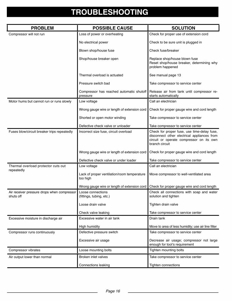
PROBLEM POSSIBLE CAUSE SOLUTIONCompressor will not run Loss of power or overheating
No electrical power
Blownshop/housefuse
Shop/house breaker open
Thermal overload is actuated
Pressure switch bad
Compressor has reached automatic shutoff pressure
Check for proper use of extension cord
Check to be sure unit is plugged in
Check fuse/breaker
Replaceshop/houseblownfuseResetshop/housebreaker,determiningwhyproblem happened
Seemanualpage13
Take compressor to service center
Release air from tank until compressor re-starts automatically
Motor hums but cannot run or runs slowly Low voltage
Wrong gauge wire or length of extension cord
Shorted or open motor winding
Defectivecheckvalveorunloader
Call an electrician
Check for proper gauge wire and cord length
Take compressor to service center
Take compressor to service centerFusesblow/circuitbreakertripsrepeatedly Incorrect size fuse, circuit overload
Wrong gauge wire or length of extension cord
Defectivecheckvalveorunderloader
Check for proper fuse, use time-delay fuse, disconnect other electrical appliances from circuit or operate compressor on its own branch circuit
Check for proper gauge wire and cord length
Take compressor to service centerThermal overload protector cuts out repeatedly
Low voltage
Lack of proper ventilation/room temperaturetoo high
Wrong gauge wire or length of extension cord
Call an electrician
Move compressor to well-ventilated area
Check for proper gauge wire and cord lengthAir receiver pressure drops when compressor shuts off
Loose connections(fittings,tubing,etc.)
Loose drain valve
Check valve leaking
Check all connections with soap and water solution and tighten
Tighten drain valve
Take compressor to service centerExcessive moisture in discharge air Excessive water in air tank
High humidity
Draintank
Movetoareaoflesshumidity;useairlinefilterCompressor runs continuously Defectivepressureswitch
Excessive air usage
Take compressor to service center
Decrease air usage; compressor not largeenough for tool’s requirement
Compressor vibrates Loose mounting bolts Tighten mounting bolts
Air output lower than normal Brokeninletvalves
Connections leaking
Take compressor to service center
Tighten connections

EXPLODED VIEW - Model # 671-049
Page 17
1
3
4
5
2
67
89
1011
1213
14
8
15
16
18
17
70
19 22
21
24
2526
27 282930
232032
33
34
35
36
37
38
39
40
4142
43
45
44
46
47
48
49 50
5152
54
56
57
58
53
55
60
61
62
63
64
65
66
67
31
59
68
69
7172
Page 18
PARTS LIST - Model #671-049
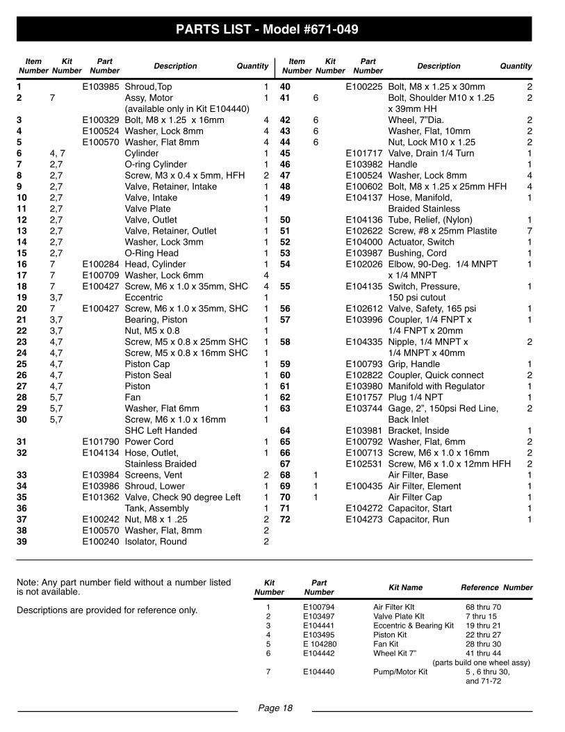
1 E103985 Shroud,Top 12 7 Assy,Motor 1 (availableonlyinKitE104440)3 E100329 Bolt,M8x1.25x16mm 44 E100524 Washer,Lock8mm 45 E100570 Washer,Flat8mm 46 4,7 Cylinder 17 2,7 O-ringCylinder 18 2,7 Screw,M3x0.4x5mm,HFH 29 2,7 Valve,Retainer,Intake 110 2,7 Valve,Intake 111 2,7 ValvePlate 112 2,7 Valve,Outlet 113 2,7 Valve,Retainer,Outlet 114 2,7 Washer,Lock3mm 115 2,7 O-RingHead 116 7 E100284 Head,Cylinder 117 7 E100709 Washer,Lock6mm 418 7 E100427 Screw,M6x1.0x35mm,SHC 419 3,7 Eccentric 120 7 E100427 Screw,M6x1.0x35mm,SHC 121 3,7 Bearing,Piston 122 3,7 Nut,M5x0.8 123 4,7 Screw,M5x0.8x25mmSHC 124 4,7 Screw,M5x0.8x16mmSHC 125 4,7 PistonCap 126 4,7 PistonSeal 127 4,7 Piston 128 5,7 Fan 129 5,7 Washer,Flat6mm 130 5,7 Screw,M6x1.0x16mm 1 SHC Left Handed 31 E101790 PowerCord 132 E104134 Hose,Outlet, 1 StainlessBraided33 E103984 Screens,Vent 234 E103986 Shroud,Lower 135 E101362 Valve,Check90degreeLeft 136 Tank,Assembly 137 E100242 Nut,M8x1.25 238 E100570 Washer,Flat,8mm 239 E100240 Isolator,Round 2
40 E100225 Bolt,M8x1.25x30mm 241 6 Bolt,ShoulderM10x1.25 2 x39mmHH42 6 Wheel,7”Dia. 243 6 Washer,Flat,10mm 244 6 Nut,LockM10x1.25 245 E101717 Valve,Drain1/4Turn 146 E103982 Handle 147 E100524 Washer,Lock8mm 448 E100602 Bolt,M8x1.25x25mmHFH 449 E104137 Hose,Manifold, 1 BraidedStainless50 E104136 Tube,Relief,(Nylon) 151 E102622 Screw,#8x25mmPlastite 752 E104000 Actuator,Switch 153 E103987 Bushing,Cord 154 E102026 Elbow,90-Deg.1/4MNPT 1 x1/4MNPT55 E104135 Switch,Pressure, 1 150psicutout56 E102612 Valve,Safety,165psi 157 E103996 Coupler,1/4FNPTx 1 1/4FNPTx20mm58 E104335 Nipple,1/4MNPTx 2 1/4MNPTx40mm59 E100793 Grip,Handle 160 E102822 Coupler,Quickconnect 261 E103980 ManifoldwithRegulator 162 E101757 Plug1/4NPT 163 E103744 Gage,2”,150psiRedLine, 2 BackInlet64 E103981 Bracket,Inside 165 E100792 Washer,Flat,6mm 266 E100713 Screw,M6x1.0x16mm 267 E102531 Screw,M6x1.0x12mmHFH 268 1 AirFilter,Base 169 1 E100435 AirFilter,Element 170 1 AirFilterCap 171 E104272 Capacitor,Start 172 E104273 Capacitor,Run 1
Item Number
Kit Number
PartNumber Description Quantity Item
NumberKit
NumberPart
Number Description Quantity
Kit Number
PartNumber Kit Name Reference Number
1 E100794 AirFilterKIt 68thru702 E103497 ValvePlateKIt 7thru153 E104441 Eccentric&BearingKit 19thru214 E103495 PistonKit 22thru275 E104280 FanKit 28thru306 E104442 WheelKit7” 41thru44 (partsbuildonewheelassy)7 E104440 Pump/MotorKit 5,6thru30, and71-72
Note:Anypartnumberfieldwithoutanumberlistedis not available.
Descriptionsareprovidedforreferenceonly.

Page 19
WARRANTY
LIMITED WARRANTY STATEMENT
MAT Holdings, Inc. warrants to the original retail purchaser that this MAT Holdings, Inc. product is free from defect in material and workmanship and agrees to repair or replace, at MAT Holdings, Inc.’s discretion, any defective product free of charge within these time periods from the date of purchase.
gOne year if the product is used for personal, family or household use;
g 90 days, if used for any other purpose, such as commercial or rental.This warranty extends to the original retail purchaser only and commences on the date of the original retail purchase.Any part of the MAT Holdings, Inc. product.manufactured or supplied by MAT Holdings, Inc. and found in the reasonable judgment of MAT Holdings, Inc. to be defective in material or workmanship will be repaired or replaced by an authorized MAT Holdings, Inc. service dealer without charge for parts and labor.The product, including any defective part, must be returned to an authorized service dealer within the warranty period. The expense of delivering the MAT Holdings, Inc. product to the dealer for warranty work and the expense of returning it back to the owner after repair or replacement will be paid by the owner. MAT Holdings, Inc.’s responsibility in respect to claims is limited to making the required repairs or replace-ments and no claim of breach of warranty shall be cause for cancellation or rescission of the contract of sale of any MAT Holdings, Inc. product. Proof of purchase will be required by the dealer to substantiate any warranty claim. All warranty work must be performed by an authorized MAT Holdings, Inc. service dealer.Thiswarrantyislimitedtoninety(90)daysfromthedateoforiginal retail purchase for any MAT Holdings, Inc. product that is used for rental or commercial purposes, or any other income-producing purpose.This warranty does not cover any MAT Holdings, Inc. product that has been subject to misuse, neglect, negligence, or ac-cident, or that has been operated in any way contrary to the operatinginstructionsasspecifiedinthisoperator’smanual.This warranty does not apply to any damage to the MAT Holdings, Inc. product that is the result of improper mainte-nance or to any MAT Holdings, Inc. product that has been alteredormodified.Thewarrantydoesnotextendtorepairsmade necessary by normal wear or by the use of parts or accessories which are either INCOMPATIBLE WITH THE MAT HOLDINGS, INC. product or adversely affect its operation, performance, or durability.MAT Holdings, Inc. reserves the right to change or improve the design of any MAT Holdings, Inc. product without as-suming any obligation to modify any product previously manufactured.
ALLIMPLIEDWARRANTIESARELIMITEDINDURATION TOTHESTATEDWARRANTYPERIOD.ACCORDINGLY, ANY SUCH IMPLIED WARRANTIES INCLUDING MER-CHANTABILITY, FITNESS FOR A PARTICULAR PUR-POSE, OR OTHERWISE, ARE DISCLAIMED IN THEIRENTIRETYAFTERTHEEXPIRATIONOFTHEAPPROPRI-ATETWO-YEAR,ONE-YEAR,ORNINETYDAYWARRAN-TY PERIOD. MAT Holdings, Inc.’s OBLIGATION UNDERTHISWARRANTYISSTRICTLYANDEXCLUSIVELYLIM-ITEDTOTHEREPAIRORREPLACEMENTOFDEFEC-TIVEPARTSANDMATHoldings,Inc.DOESNOTASSUMEORAUTHORIZEANYONETOASSUMEFORTHEMANYOTHER OBLIGATION. SOME STATES DO NOTALLOWLIMITATIONSONHOWLONGAN IMPLIEDWARRANTYLASTS,SOTHEABOVELIMITATIONMAYNOTAPPLYTOYOU.MATHoldings,Inc.ASSUMESNORESPONSIBILITYFORINCIDENTAL,CONSEQUENTIAL,OROTHERDAM-AGES INCLUDING, BUT NOT LIMITED TO, EXPENSEOFRETURNINGTHEMATHoldings, Inc.PRODUCTTOANAUTHORIZEDSERVICEDEALERANDEXPENSEOFDELIVERING IT BACK TO THE OWNER, MECHANIC’STRAVELTIME,TELEPHONEORTELEGRAMCHARGES,RENTALOFALIKEPRODUCTDURINGTHETIMEWAR-RANTY SERVICE IS BEING PERFORMED, TRAVEL,LOSS OR DAMAGE TO PERSONAL PROPERTY, LOSSOFREVENUE,LOSSOFUSEOFTHEPRODUCT,LOSSOFTIME,ORINCONVENIENCE.SOMESTATESDONOTALLOWTHEEXCLUSIONORLIMITATIONOFINCIDEN-TALORCONSEQUENTIALDAMAGES,SOTHEABOVELIMITATIONOREXCLUSIONMAYNOTAPPLYTOYOU.Thiswarrantygivesyouspecific legalrights,andyoumayalso have other rights which vary from state to state.This warranty applies to all MAT Holdings, Inc. products man-ufactured or supplied by MAT Holdings, Inc. and sold in the United States and Canada.Tolocateyournearestservicedealer,dial1-888-859-4549.

Page 20
NOTES

MANUAL DEL OPERADORCompresor de aire portportátilde 98,4 LITROS (26 galones)F2S26VWDVP/ 671-049
Su compresor de aire ha sido diseñado y fabricado de conformidad con las estrictas normas de Husky parabrindarfiabilidad,facilidaddeusoyseguridadparaeloperador.Coneldebidocuidado,lebrindarámuchosañosdesólidoyeficientefuncionamiento.
Le agradecemos la compra de un producto Husky.
GUARDE ESTE MANUAL PARA FUTURAS CONSULTAS
ADVERTENCIA: Para reducir el riesgo de lesiones, el usuario debe leer y comprender el manual del operador antes de usar este producto.
02/09/2009
Estaherramientaofrecenumerosascaracterísticasparahacermásagradableyplacenterosuuso.Eneldiseñodeestepro-ductosehaconferidoprioridadalaseguridad,eldesempeñoylafiabilidad,porlocualsefacilitasumanejoy mantenimiento.
PRECAUCIÓN Estecompresorestádiseñadoparautilizarseenunciclodeserviciodel50%.
PELIGRO
Estecompresor(obomba)noestáequipadoydebeevitarseutilizarloparasuministrarairepararespirar.EsnecesarioequipoadicionalparafiltrarypurificardebidamenteelaireafindequecumplalasespecificacionesmínimasdeGradoDpararespiración,segúnseexplicaenlaEspecificacióndeProductosG7.1-1966delaAsociacióndeProveedoresdeEquipodeGasComprimido(CompressedGasAssociation),OSHA29CFR1910.134.CompressedGasAssociation,422221WalneyRoad,FifthFloor,Chantilly,VA20151-2923,(703)788-2700,www.cganet.com.Talequipoadicionalnohasido examinado y no debe suponerse o deducirse ninguna conclusión con respecto al correcto uso del aire de respiración. Si se altera de cualquier forma este compresor, quedan anuladas todas las garantías presentes. Husky y MAT Holdings, Inc., se eximen de toda responsabilidad de cualquier tipo por cualquier pérdida, lesión corporal o daño material.
ÍNDICE DE CONTENIDO
g Reglasdeseguridadgenerales. . . . . . . . . . . . . . . . . . . . . . . . . . . . . . . . . . . . . . . . . . . . . . . . . . . . . .1-2g Reglasdeseguridadespecíficas . . . . . . . . . . . . . . . . . . . . . . . . . . . . . . . . . . . . . . . . . . . . . . . . . . . . . 3g Símbolos . . . . . . . . . . . . . . . . . . . . . . . . . . . . . . . . . . . . . . . . . . . . . . . . . . . . . . . . . . . . . . . . . . . . . . .4-5g Aspectos eléctricos . . . . . . . . . . . . . . . . . . . . . . . . . . . . . . . . . . . . . . . . . . . . . . . . . . . . . . . . . . . . . . . . 6g Glosariodetérminos . . . . . . . . . . . . . . . . . . . . . . . . . . . . . . . . . . . . . . . . . . . . . . . . . . . . . . . . . . . . . . . 7g Características. . . . . . . . . . . . . . . . . . . . . . . . . . . . . . . . . . . . . . . . . . . . . . . . . . . . . . . . . . . . . . . . . . .8-9g Armado . . . . . . . . . . . . . . . . . . . . . . . . . . . . . . . . . . . . . . . . . . . . . . . . . . . . . . . . . . . . . . . . . . . . . . . . . 9g Funcionamiento . . . . . . . . . . . . . . . . . . . . . . . . . . . . . . . . . . . . . . . . . . . . . . . . . . . . . . . . . . . . . . . .10-13g Mantenimiento . . . . . . . . . . . . . . . . . . . . . . . . . . . . . . . . . . . . . . . . . . . . . . . . . . . . . . . . . . . . . . . . . . . 14g Utilizacióndelaherramientaneumática . . . . . . . . . . . . . . . . . . . . . . . . . . . . . . . . . . . . . . . . . . . . . . . 16g Solución de problemas . . . . . . . . . . . . . . . . . . . . . . . . . . . . . . . . . . . . . . . . . . . . . . . . . . . . . . . . . . . . 15g Diagramadeloscomponentes . . . . . . . . . . . . . . . . . . . . . . . . . . . . . . . . . . . . . . . . . . . . . . . . . . . . . . 17g Lista de las piezas. . . . . . . . . . . . . . . . . . . . . . . . . . . . . . . . . . . . . . . . . . . . . . . . . . . . . . . . . . . . . . . . 18g Garantía. . . . . . . . . . . . . . . . . . . . . . . . . . . . . . . . . . . . . . . . . . . . . . . . . . . . . . . . . . . . . . . . . . . . . . . . 19g Notas . . . . . . . . . . . . . . . . . . . . . . . . . . . . . . . . . . . . . . . . . . . . . . . . . . . . . . . . . . . . . . . . . . . . . . . . . . 20
INTRODUCCIÓN
ADVERTENCIA
Lea y comprenda todas las instrucciones. El incumplim-iento de las instrucciones señaladas abajo puede causar descargas eléctricas, incendios y lesiones serias.
GUARDE ESTAS INSTRUCCIONES
ÁREA DE TRABAJO
g Mantenga limpia y bien iluminada el área de trabajo. Una mesa de trabajo mal despejada y una mala iluminación son causas comunes de accidentes. El piso debe no estar resbaloso debido a la presencia de cera o polvo.
gNo utilice herramientas motorizadas en atmósferas explosivas, como las existentes alrededor de líquidos, gasesypolvosinflamables.Lasherramientaseléctricas generan chispas que pueden encender el polvo y los vapores inflamables.
g Mantenga alejados a los circunstantes, niños ydemás presentes al utilizar herramientas. Toda distracción puede causar la pérdida del control de la herramienta.
g Utilice el compresor de aire en un área abierta por lo menos a 46 cm (18 pulg.) de cualquier pared u objeto que pudiera restringir el flujo de aire fresco a las aber turas de ventilación.
SEGURIDAD ELÉCTRICA
g Evite el contacto del cuerpo con las superficies de objetos conectados a tierra, como las tuberías, radiadores, estufas y refrigeradores. Existe un mayor riesgo de descargaseléctricassielcuerpoestáencontactocontierra.
g No exponga las herramientas eléctricas a la lluvia ni a condiciones de humedad. La introducción de agua en una herramienta eléctrica aumenta el riesgo de descargas eléctricas.
g No maltrate el cordón eléctrico. Nunca use el cordón eléctrico para portar la herramienta ni para sacar la clavija de una toma de corriente. Mantenga el cordón lejos del calor, aceite, bordes afilados y piezas móviles. Cambie de inmediato todo cordón eléctrico dañado. Los cordones eléctricos dañados aumentan el riesgo de descargas eléctricas.
g Al utilizar una herramienta eléctrica en el exterior, utilice un cordón eléctrico de extensión que lleve las marcas “W-A” o “W”. Estoscordoneseléctricosestán aprobados para el uso en el exterior y reducen el riesgo de descargas eléctricas.
SEGURIDAD PERSONAL
g Al cargar, utilizar y dar servicio a esta herramienta, el operador y demás personas SIEMPRE deben llevar puesta protección ocular que cumpla con las especifi caciones ANSI y ofrezca protección contra partículas que salgan disparadas del FRENTE y de los LADOS. Se requiere protección ocular como protección contra sujetadores y desechos que salgan disparados, los cuales pueden causar lesiones oculares serias.
g Tanto el patrón como el operador deben asegurarse de que se use protección ocular adecuada. Recomendamos una careta protectora de visión amplia encima de los anteojos normales o de los anteojos de seguridad que ofrecen protección frontal y lateral contra partículas que salen disparadas. Siempre póngase protección ocular con lamarcadecumplimientodelanormaANSIZ87.1.
g En algunos entornos se requiere protección adicional. Porejemplo,eneláreadetrabajopuedehaberexposición a un nivel de ruido que puede dañar el oído. El patrón y el operador deben asegurarse de contar con toda la protección auditiva necesaria y de que sea usada por el operador mismoydemáspersonaspresenteseneláreadetrabajo. En algunos entornos se requiere el uso de equipo de protección para la cabeza. Cuando se requiera, el patrón y el operador deben asegurarse de que la protección usada para la cabeza lleve la marca de cumplimiento con la norma ANSIZ89.1.
g Permanezca alerta, preste atención a lo que esté haciendo, y aplique el sentido común al utilizar herramientas eléctricas. No utilice la herramienta si está cansado o se encuentra bajo los efectos de alguna droga, alcohol o medicamento. Un momento de inatención al utilizar una herramienta eléctrica puede causar lesiones corporales serias.
g Vístase adecuadamente. No vista ropas holgadas ni joyas. Recójase el cabello si está largo. Mantenga el cabello, la ropa y los guantes alejados de las piezas móviles. Las ropas holgadas, las joyas y el cabello largo pueden engancharse en las piezas móviles.
g No estire el cuerpo para alcanzar mayor distancia. Mantenga una postura firme y buen equilibrio en todo momento. Laposturafirmeyelbuenequilibriopermiten un mejor control de la herramienta en situaciones inesperadas.
g Use equipo de seguridad. Siempre póngase protección ocular. Cuando lo exijan las circunstancias debe ponerse careta contra el polvo, zapatos de seguridad antiderrapantes, casco o protección auditiva.
g No utilice la unidad al estar en una escalera o en un soporte inestable. Una postura estable sobre una superficie sólida permite un mejor control de la herramienta en situaciones inesperadas.
Página 1
REGLAS DE SEGURIDAD GENERALES
EMPLEO Y CUIDADO DE LA HERRAMIENTA
g No sobrepase la presión nominal de ningún componente del sistema.
g Proteja de daños y perforaciones los conductos de material y de aire. Mantenga la manguera y el cordón de corriente lejos de objetos afilados, productos químicos derramados, aceite, solventes y pisos mojados.
g Antes de usar la unidad revise las mangueras para ver muestran daños o desgaste, asegurándose de que estén seguras todas las conexiones. No utilice la unidad siencuentraalgúndefecto.Adquieraunamangueranueva o lleve la unidad a un centro de servicio autorizado para que la examinen y reparen.
g Purgue lentamente todas las presiones internas del sistema. El polvo y la basura pueden ser dañinos.
g Guarde las herramientas que no estén en uso fuera del alcance de los niños y de toda persona no capacitada en el uso de las mismas. Las herramientas son peligrosas en manos de personas no capacitadas en el uso de las mismas.
g Dé mantenimiento con cuidado a las herramientas. Siga todas las instrucciones de mantenimiento. Las herramientas que han recibido el debido mantenimiento se controlan con mayor facilidad.
g Revise para ver si hay desalineación o atoramiento de piezas móviles, ruptura de piezas o toda otra condición que pueda afectar el funcionamiento de la herramienta. Si se daña la herramienta, llévela a servicio antes de
volver a utilizarla. Numerosos accidentes son causados por herramientas mal cuidadas.
g Nunca apunte ninguna herramienta hacia sí u otras personas.
g Mantenga el exterior del compresor de aire seco, limpio y libre de aceite y grasa. Siempre utilice un paño limpio para la limpieza de la unidad.Nunca utilice fluidos para frenos, gasolina, productos a base de petróleo ni solventes fuertes para limpiar la unidad. Con el cumplimiento de esta regla se reduce el riesgo de deterioro del alojamiento de plásticodelaunidad.
SERVICIO
g El servicio de la herramienta sólo debe ser efectuado por personal de reparación calificado. Todo servicio o mantenimientoefectuadoporpersonalnocalificadopuede significarunriesgodelesiones.
g Desconecte el suministro de corriente, abra la válvula de drenaje para purgar la presión del tanque y permitir que se drene el agua, y por último permita que se enfríe el compresor antes de darle servicio. Girela completamente a la izquierda la perilla de regulación de la presión antes de apagar el compresor.
g Al dar servicio a una herramienta, sólo utilice piezas de repuesto idénticas. Siga las instrucciones señaladas en la sección “Mantenimiento” de este manual. El empleo de piezas no autorizadas o el incumplimiento de las instrucciones de mantenimiento puede significar un riesgo de lesiones.
Página 2
REGLAS DE SEGURIDAD GENERALES
g Familiarícese con su herramienta eléctrica. Lea cuidadosamente el manual del operador. Aprenda sus usosylimitaciones,asícomolosposiblespeligrosespecíficos de esta herramienta. Con el cumplimiento de esta regla se reduce el riesgo de una descarga eléctrica, incendio o lesión seria.
g Después del uso de cada día, drene toda la humedad del tanque. Sinovaautilizarselaunidaddurantealgún tiempo,esmejordejarabiertalaválvuladedrenajehasta cuandovuelvaausarseaquélla.Deestamanerasepermite drenar completamente la humedad y se impide la corrosión del interior del tanque.
g Riesgo de incendio o explosión. Sólo rocíe líquidos inflamablestalescomopinturasolacas.Nuncarocíelíquidos inflamablesenunárea limitada.Eláreaderociadodebe estar bien ventilada. No fume mientras esté rociando con pistola,ni rocíedondehayapresenteschispasoflamas. Mantengaloscompresorestanlejosdeláreadepinturay de vapores explosivos como sea posible, por lo menos a 4,6m(15pies).
g Riesgo de estallido. No ajuste el regulador para producir unapresióndesalidasuperioralapresiónmáximamarcada en el aditamento. No utilice una presión superior a la presión nominalmáximadelcompresor.
g Si va a conectar este producto a un circuito protegido con fusibles, utilice fusibles con retardo de tiempo.
g Para reducir el riesgo de una descarga eléctrica no expongalaunidadalalluvia.Guardelaunidadenelinterior.
g Inspeccione anualmente el tanque para ver si tiene herrumbre, picaduras u otras imperfecciones que pudieran afectar la seguridad de la unidad. Nunca suelde el tanque de aire ni perfore agujeros en el mismo.
g Asegúrese de que la manguera no esté obstruida ni enganchada. Si la manguera se enreda o engancha puede causar una pérdida del equilibrio o postura y puede dañarse.
REGLAS DE SEGURIDAD ESPECÍFICAS

Página 3
REGLAS DE SEGURIDAD ESPECÍFICAS
g Solamente utilice el compresor de aire para el propósito especificado. No altere ni modifique la unidad con respecto a su diseño y funcionamiento originales.
gSiempre tenga presente que el uso y manejo indebidos de esta herramienta puede causarle lesiones a usted y a otras personas.
gNunca deje desatendida ninguna herramienta con la manguera de aire conectada.
gNo utilice esta herramienta si no tiene una etiqueta de advertencia.
gNo continúe usando ninguna herramienta o manguera que tenga fugas de aire o que no funcione correctamente.
g Siempre desconecte el suministro de aire y el de corriente antes de efectuar ajustes, dar servicio a la herramientaocuandonoestéusándoseésta.
gNo intente tirar de la manguera ni acarrear el compresor tomándolo por la misma.
g Una herramienta determinada puede necesitar más aire del que este compresor es capaz de suministrar.
g Nunca tienda equipaa con herramienta con aire conectado. Almacenar el instrumento con aire conectado puede tener como resultado despedir y herida inesperado personal, grave y posible.
gSiempre siga todas las reglas de seguridad recomenda das por el fabricante de la herramienta de aire, además de todas las reglas de seguridad del compresor de aire. Con el cumplimiento de esta regla se reduce el riesgo de lesiones serias.
g Nunca dirija un chorro de aire comprimido hacia personas o animales. Tenga cuidado de no soplar polvo o tierra hacia sí u otras personas. Con el cumplimiento de esta regla se reduce el riesgo de posibles lesiones serias.
gProtéjase los pulmones. Use una careta o mascarilla contra el polvo si la operación genera mucho polvo. Con el cumplimiento de esta regla se reduce el riesgo de lesiones corporales serias.
g No utilice este compresor de aire para rociar productos químicos. Pueden resultar afectados los pulmones debido a la inhalación de emanaciones tóxicas. Puede ser necesario utilizar un respirador en entornos polvorientos o al rociar pintura. No acarree la unidad mientras esté pintando.
g Inspeccione periódicamente los cordones eléctricos y las mangueras de las herramientas, y si están dañados, permita que los reparen en el centro de servicio autorizado más cercano de la localidad. Observe constantemente la ubicación del cordón eléctrico. Con el cumplimiento de esta regla se reduce el riesgo de una descarga eléctrica o incendio.
g Nunca use un adaptador eléctrico con esta clavija de conexión a tierra.
g Revise para ver si hay piezas dañadas. Antes de seguir utilizando el compresor o la herramienta de aire, es necesario inspeccionar cuidadosamente toda protección o pieza dañada para determinar si funcionará correcta- mente y desempeñará la función a la que está destinada. Verifique la alineación de las partes móviles, que no haya atoramiento de las mismas, que no haya piezas rotas, el montaje de las piezas y cualquier otra condición que pudiera afectar su funcionamiento. Toda protección o pieza que esté dañada debe repararse apropiadamente o reemplazarse en un centro de servicio autorizado. Con el cumplimiento de esta regla se reduce el riesgo de una descarga eléctrica, incendio o lesión grave.
g Asegúrese de que esté en buen estado el cordón de extensión. Al utilizar un cordón de extensión, utilice uno del suficiente calibre para soportar la corriente que consume el producto. Se recomienda que los con ductores sean de calibre 14 (A.W.G.) por lo menos para un cordón de extensión de 15 metros (50 pies) de largo o menos. No se recomienda utilizar un cordón con más de 30 metros (100 pies) de largo. Si tiene dudas, utilice un cordón del calibre más grueso siguiente. Cuanto menor es el número de calibre, mayor es el grueso del cordón. Uncordóndeun calibre insuficiente causauna caída en el voltaje de línea, y produce recalentamiento y pérdida de potencia.
g Guarde estas instrucciones. Consúltelasconfrecuencia y empléelas para instruir a otras personas que puedan utilizar este compresor de aire. Si presta a alguien esta herramienta, facilítele también las instrucciones.

Página 4
Es posible que se empleen en esta herramienta algunos de los siguientes símbolos. Le suplicamos estudiarlos y aprender susignificado.Unacorrectainterpretacióndeestossímboloslepermitiráutilizarmejorydemaneramásseguralaherramienta.
SÍMBOLOS
SÍMBOLO NOMBRE DENOMINACIÓN/EXPLICACIÓN
V Volts VoltajeA Amperes Corriente
Hz Hertz Frecuencia(ciclosporsegundo)Corriente alterna Type of currentFabricaciónClaseII Double-insulatedconstructon
Alertadecondicioneshúmedas Noexponga launidada la lluviani lauseen lugareshúme-dos.
Lea el manual del operador Para reducir el riesgo de lesiones, el usuario debe leer y com-prender el manual del operador antes de usar este producto.
Protección ocular Cuando utilice este producto, póngase siempre gafas de segu-ridad, anteojos protectores con protección lateral, o una careta protectora completa.
Alerta de seguridad Precauciones para su seguridad.
Riesgodeestallido No ajuste el regulador para producir una presión de salida su-perioralapresiónmáximamarcadaeneladitamento.No utilice unapresiónsuperioralapresiónnominalmáximadelcompresor
Riesgodeestallidooexplosión Eláreaderociadodebeestarbienventilada.Nofumemien-tras esté rociando con pistola, ni rocíe donde haya presentes chispasoflamas.Mantengaloscompresorestanlejosdeláreade pintura y de vapores explosivos como sea posible, por lo menosa4,6m(15pies).
Riesgodedescargaeléctrica Voltaje peligroso: Desconecte del suministro de corriente launidad antes de proporcionarle servicio. El compresor debe conectarse a tierra.
Superficiecaliente Para reducir el riesgo de lesiones corporales o daños materi-alesevitetocartodasuperficiecaliente.
Riesgoderespiración El aire obtenido directamente del compresor nunca debe uti-lizarse para consumo humano.

Página 5
SÍMBOLOS
Lassiguientespalabrasdeseñalizaciónysussignificadostienenelobjeto de explicar los niveles de riesgo relacionados con este producto.
SÍMBOLO SEÑAL SIGNIFICADO
PELIGRO Indicaunasituaciónpeligrosainminente,lacual,sinoseevita,causarálamuerteole-siones serias.
ADVERTENCIA Indica una situación peligrosa posible, la cual, si no se evita, podríacausar la muerte o lesiones serias.
PRECAUCIÓN Indica una situación peligrosa posible, la cual, si no se evita, podríacausar lesiones menores o leves.
PRECAUCIÓN (Sinelsímbolodealertadeseguridad.)Indicaunasituaciónquepuedeproducirdañosmateriales.
SERVICIOEl servicio de la herramienta requiere extremo cuidado y cono-cimientos técnicos, por lo cual sólo debe ser efectuado por un técnicodeserviciocalificado.Paradarservicioalaherramienta,le sugerimos llevarla al CENTRO DE SERVICIO AUTORIZADO de su preferencia para que la reparen. Al dar servicio a la uni-dad, sólo utilice piezas de repuesto idénticas.
ADVERTENCIA
Para evitar lesiones corporales serias, no intente utilizar este producto sin haber leído y comprendido totalmente elmanualdeloperador.Guardeestemanualdelopera-doryestúdielofrecuentementeparalograrunfunciona-miento seguro y continuo de este producto, y para instruir a otras personas quienes pudieran utilizarlo.
Cualquier herramienta eléctrica en funcionamiento puede lanzar objetos hacia los ojos, lo cual puede causar serios daños a los mismos. Antes de comenzar a utilizar una herramienta eléctrica, póngase siempre gafas de seguridad, anteojos protectores con protección lateral o careta completa cuando sea necesario.Recomendamoslacaretaprotectoradevisiónampliaencimadelosanteojosnormales,olosanteojosprotectoresestándarconprotección lateral.Siemprepóngaseprotecciónocularcon lamarcadecumplimientodelanormaANSIZ87.1.
ADVERTENCIA
GUARDE ESTAS INSTRUCCIONES

CORDONES DE EXTENSIÓNSólo utilice cordones de extensión de tres conductores con clavijas de tres patillas y receptáculos de tres polos queacepten la clavija del cordón del compresor. Al utilizar el com-presor de aire a una distancia considerable del suministro de corriente, asegúrese de utilizar un cordón de extensión delgruesosuficienteparasoportarelconsumodecorrientedelcompresor.Uncordóndeextensióndeungruesoinsuficientecausaunacaídaenelvoltajede línea,ademásdeproducirunapérdidadepotenciayunrecalentamientodelmotor.Bás-ese en la tabla suministrada abajo para determinar el calibre mínimo requerido de los conductores del cordón de extensión. Solamente deben utilizarse cordones con forro redondo regis-tradosenUnderwriter’sLaboratories(UL).
Al trabajar a la intemperie con el compresor, utilice un cordón de extensión fabricado para uso en el exterior. Tal caracterís-ticaestáindicadaconlasletras“WA”enelforrodelcordón.Antes de utilizar un cordón de extensión, inspecciónelo para versitieneconductoresflojosoexpuestosyaislamientocor-tado o gastado.
ADVERTENCIA Mantengaelcordóndeextensiónfueradeláreadetrabajo. Al trabajar con una herramienta eléctrica, coloque el cordón de tal manera que no pueda enredarse en la madera, herramientas o ninguna obstrucción. La inobservancia de esta advertencia puede causar lesiones serias.
ADVERTENCIA
Inspeccione los cordones de extensión cada vez antes de usarlos.Si estándañados, reemplácelos de inmediato.Nunca utilice el compresor con un cordón dañado, ya que si toca la parte dañada puede producirse una descarga eléctrica, y las consecuentes lesiones serias.
CONEXIÓN ELÉCTRICAEstecompresordeaireestáaccionadoporunmotoreléctricofabricadoconprecisión.Debeconectarseúnicamenteauna línea de voltaje de 120 V, 60 Hz, de corriente alterna sola-mente (corriente normal para uso doméstico). No utilice esta herramientaconcorrientecontinua(c.c.).Unacaídaconsiderablede voltaje causa una pérdida de potencia y el recalentamiento del motor. Si el compresor no funciona al conectarlo en una toma de corriente, vuelva a revisar el suministro de corriente.
VELOCIDAD Y CABLEADOLavelocidadenvacíodeestecompresores3450rpmaproxi-madamente. Esta velocidad no es constante y disminuye du-rante el corte o con un voltaje bajo. En cuanto al voltaje, el ca-bleado de un taller es tan importante como la potencia nominal del motor. Una línea destinada sólo para luces no puede ali-mentar el motor de una herramienta eléctrica. El cable con el calibresuficienteparaunadistanciacortaserádemsiadodel-gado para una mayor distancia. Una línea que alimenta una herramientaeléctricaquizánoseasuficienteparaalimentardos o tres herramientas.INSTRUCCIONES DE CONEXIÓN A TIERRAEste producto se debe conectar a tierra. En caso de un mal funcionamiento o desperfecto, la conexión a tierra brinda a la corriente eléctrica una trayectoria de mínima resistencia para disminuir el riesgo de una descarga eléctrica. Este compresor deaireestáequipadodeuncordóneléctricoconunaclavijadotada de un conductor de conexión a tierra. La clavija debe conectarse en una toma de corriente igual que esté instalada y conectada a tierra correctamente, de conformidad con los códi-gos y reglamentos de la localidad.Nomodifiquelaclavijasuministrada.Sinoentraenlatomadecorriente,llameaunelectricistacalificadoparaqueinstaleunatoma de corriente adecuada. Si se conecta de forma incorrecta el conductor de conexión a tierra del equipo puede presentarse un riesgo de descarga eléctrica.Elconductorconaislamientoquetieneunasuperficieexteriorverde con o sin tiras amarillas es el conductor de conexión a tierra del equipo. Si es necesario reparar o reemplazar el cable eléctrico o el enchufe, no conecte el conductor de conexión a tierradelequipoaningúnterminaldehojaplana(unterminalenergizado).Consulteaunelectricistacalificadootécnicodeserviciosinoha comprendido completamente las instrucciones de conexión atierraosinoestásegurosilaherramientaestáconectadaatierra correctamente.Repareoreemplacedeinmediatotodocordóndañadoogastado.Este compresor de aire debe utilizarse conectado a un circu-itoconuna tomadecorrientecomo lamostradaen lafigura1.Tambiéndisponedeunapatilladeconexióna tierracomola mostrada. Este producto debe conectarse a tierra. Conecte el producto solamente a un tomacorriente que tenga la misma configuraciónqueelenchufe.Noutiliceunadaptadorconesteproducto.
Figura1
Página 6
ASPECTOS ELÉCTRICOS
**Amperaje(apareceenlaplacadedatosdelcompresor)0 - 2.0 2.1-3.4 3.5-5.0 5.1-7.0 7.1-12.0 12.1-16.0
Longitud del cordón Calibre conductores (A.W.G.)
25´ 16 16 16 16 14 1450´ 16 16 16 14 14 12100´ 16 16 14 12 10 —
**Seusaenloscircuitosdecalibre12,de20A.NOTA:AWG=Calibreconductoresnormaamericana
PATILLA DE cONExIóN A TIERRA
TOMA DE cORRIENTE DE120 V cON cONExIóN A TIERRA
Página 7
GLOSARIO DE TÉRMINOS
BombaEs el dispositivo que produce el aire comprimido mediante un pistón de vaivén contenido dentro del cilindro.
Filtro de aireEs un elemento poroso contenido dentro de un alojamiento de metaloplásticounidoalcilindrode laculatadelcilindrodelcompresor, el cual sirve para eliminar las impurezas del aire de entrada del compresor.
Interruptor de Encendido/Apagado ManualControl que enciende o apaga el compresor de aire. El inter-ruptordepresiónnoenciendeycontrolaautomáticamenteel compresor a menos que el interruptor de Encendido/Apa-gado manual esté en la posición de ENCENDIDO.
Interruptor de presiónSirve para controlar los ciclos de encendido y apagado del compresor. Apaga el compresor cuando se alcanza la presión de interrupción del tanque y arranca el compresor cuando la presión del aire desciende abajo de la presión de interrup-ción.
Interruptor de sobrecarga térmicaSirveparaapagarautomáticamenteel compresorsi la tem-peratura del motor eléctrico se excede de un límite predeter-minado.
Manómetro del tanqueSirve para indicar la presión interna del tanque.
Manómetro reguladorMuestra la presión actual en el conducto. La presión del con-ducto se ajusta girando la perilla de regulación de presión.
Motor eléctricoEs el dispositivo encargado de suministrar la fuerza rotatoria necesaria para accionar la bomba del compresor.
NPT (Norma Nacional de Roscado de Tubos)Debeutilizarseunacinta selladorade roscaspara tenerunsello a prueba de fugas en las conexiones roscadas de tu-bos.
SCFM (Pies cúbicos estándar por minuto)La unidad de medida de suministro de aire.
Perilla de regulación de presiónSirve para regular la presión de la salida de aire dirigida a la herramienta. Es posible aumentar o disminuir la presión pre-sente en la salida ajustando esta perilla de control.
Presión de activaciónEslapresiónbajaalacualarrancaautomáticamenteelmo-tor.
Presión de interrupciónEslapresiónaltaalacualseapagaautomáticamenteelmo-tor.
PSI (Libras por pulgada cuadrada)Son las unidades de medida de la presión ejercida por la fuer-za del aire. La presión real en PSI es medida por el manómet-ro del compresor.
Tanque de aireEs un componente cilíndrico que contiene el aire comprimido.
Válvula de retenciónEs un dispositivo cuya función es impedir que el aire comprim-ido se regrese del tanque de aire a la bomba del compresor.
Válvula de presión alivioSu funciónes impedirque lapresióndelaireasciendamásalládeunlímitepredeterminado.

Página 8
CARACTERÍSTICAS
ESPECIFICACIONES DEL PRODUCTOPotencia de funcionamiento ..........................................1,5HPCapacidad del tanque de aire...........................98,4L(26gal.)Presión de aire .............................1034,4kPA(150psi),máx.Suministro de aire................................113,3l/min(4,0SCFM)
141,6l/min(5,0SCFM)
Lubricación ........................................ Lubricación permanenteManómetros...............50,8mm(2pulg.)dediámetroCorrientede entrada .........................120V,60Hz,15,0A,sólocorr.alt.Peso neto ..................................................... 50,3kg(111,0lb)
Figura2
MANóMETRO DELPERILLA DE
REGULAcIóNMANóMETRO DEL
TANQUE
PERILLA DE REGULAcIóNDE PRESIóN ENcENDIDO /
APAGADO
VALVULA DE SEGURIDAD
MANGO DE AcARREO MOTOR

Página 9
CARACTERÍSTICAS
MANGOElcompresordeaireestáequipadoconunmangodetrans-porte acolchado para facilitar el uso.
MOTOR INDUCCIÓN DE LUBRICACIÓN PERMANENTEEl compresor incorpora cojinetes lubricados permanentemente.
PERILLA DE REGULACIÓN DE PRESIÓNPara ajustar la cantidad de aire suministrada a través de la manguera, utilice la perilla de regulación de presión.
MANÓMETRO REGULADORLa presión actual del conducto aparece en el manómetro regulador. Esta presión puede ajustarse girando la perillade regulación de presión.
VÁLVULA DE PRESIÓN ALIVIOLaválvuladepresiónalivioestádiseñadaparasoltaraireautomáticamentesilapresióndelaparatoreceptordelairesobrepasaellímitemáximoprefijado.
MANÓMETRO DEL TANQUEEl manómetro indica la presión del aire en el interior del tanque.
ARMADOCÓMO CONECTAR LA MANGUERA Y EL ACOPLADOR RÁPIDOVea la figura 3.
gAsegúrese de que esté apagado y desconectado el compresor de aire.
Instruccionesdeconfiguración: 1. Elcompresorseentregaarmadodefábricaylistopara suuso.Revisetodosloscomponentesparaasegurarse de que estén armados correctamente; por ejemplo, los soportes de goma, las ruedas, la manija, los conectores rápidos,loscalibradores,laválvuladeseguridad,elfil trodeaire,laválvuladedrenaje,etc. 2. Aplique cinta para roscas a las conexiones roscadas de la manguera y conecte el acoplador rápido a la manguera utilizando una llave (la llave no se suministra). 3.Apliquecintapararoscasalasconexionesroscadasdel enchufe macho y conecte el enchufe hembra a la manguera utilizando una llave (la llave no se suministra).
gGirecompletamentealaizquierdalaperilladeregulación de presión.
g Introduzca el extremo del adaptador para manguera de la manguera de aire en el extremo del acoplador hembra en el compresor de aire.
ACOPLADOR HEMBRA
ADAPTADOR DE MANGIERA
PERILLA DE REGULACÓNDE PRESIÓN
APAGADO
Figura3
FAMILIARÍCESE CON EL COMPRESORVea la Figura 2.El uso seguro que este producto requiere la comprensión de la información impresa en la herramienta y en el manual del operador así como ciertos conocimientos sobre el proyecto a realizar. Antes de usar este producto, familiarícese con todas las características de funcionamiento y normas de seguridad.

DESEMPAQUETADOgExtraigacuidadosamentedelacajalaherramienta.Asegúresedequeesténpresentestodoslosartículosenumeradosen la lista de empaquetado.
g Inspeccione cuidadosamente la herramienta para asegurarse de que no haya sufrido ninguna rotura o daño durante el transporte.
g No deseche el material de empaquetado sin haber inspeccionado cuidadosamente la herramienta y haberla utilizado satisfactoriamente.
gSihaypiezasdañadasofaltantes,lesuplicamosllamaral1-888-859-4549,dondelebrindaremosasistencia.
LISTA DE EMPAQUETADO(1)Compresorneumático(1)Manualdeinstrucciones(1)Mangueradeaire(1)Cintapararoscas(1)Enchufesmachosde1/4”NPT(1)Acopladorrápidode1/4”NPT(1)Llavedeimpactode1/2”(1)Trinquetede3/8”
Página 10
FUNCIONAMIENTO
ADVERTENCIA Si faltan piezas, no utilice este producto sin haber reem-plazado todas las piezas faltantes. La inobservancia de esta advertencia puede causar lesiones serias.
ADVERTENCIA No intentemodificaresteproductonihaceraccesorios no recomendados para la misma. Cualquier alteración o modificación constituye maltrato el cual puede causar una condición peligrosa, y como consecuencia posibles lesiones corporales serias.
ADVERTENCIA Noconecteelconectordeinfladoolaotraherramienta en el extremo abierto de la manguera sin haber efectuado el procedimiento inicial.
ADVERTENCIA
No permita que su familarización con las productos lo vuelva descuidado. Tenga presente que un descuido de uninstanteessuficienteparacausarunalesiónseria.
ADVERTENCIA Cuando utilice productos, póngase siempre gafas de seguridad o anteojos protectores con protección lateral. La inobservancia de esta advertencia puede causar el lanzamiento de objetos a los ojos, y por consecuencia posibles lesiones serias.
ADVERTENCIANoutiliceningúnaditamentooaccesorionorecomendadopor el fabricante de este producto. El empleo de adita-mentos o accesorios no recomendandos podría causar lesiones serias.
CAUTIONNoutilicelaunidadenningúnentornopolvorientoocon-taminado de cualquier forma. Si se utiliza el compresor de aire en este tipo de entorno puede dañarse.
USOSLos compresores de aire se utilizan en una variedad de sistemas de suministro de aire. Las mangueras, conectores, herramientas de aire y accesorios deben corresponder a la capacidad del compresor de aire.
Esta herramienta puede emplearse para los fines enumer-ados abajo:
g Accionamiento de algunas herramientas de aire deber ligero
gInflado de neumáticos, colchones de aire, equipo para deportes, etc. (Los accesorios de la inflación vendieron separadamente)

Página 11
FUNCIONAMIENTO
CÓMO ENCENDER/APAGAR EL COMPRESOR DE AIREVea la Figura 4.
gGireelinterruptordecorrientealaposicióndeENCENDIDO para encender el compresor.
g Para apagar el compresor, gire el interruptor de corriente a la posición de APAGADO.
USO DEL COMPRESORVea las figuras 4-5.
gAsegúrese de que el interruptor de corriente esté en la posición de APAGADO y el compresor esté desconectado.
gSi no está instalada aún la manguera, conéctela al compresor de la forma indicada previamente.
gConecteeladaptadormachode6,35mm(1/4pulg.)NPT de la herramienta en el extremo del acoplador hembra de la manguera de aire.
ADVERTENCIASiempre asegúrese de que el interruptor esté en la posicióndeAUTOMÁTICO(O)yelmanómetroregulador indique cero antes de cambiar de herramienta de aire o desconectar la manguera de la salidad de aire. La in-observancia de esta advertencia puede causar lesiones corporales serias.
gGirelaperilladereguladorelflujoaladerechaalairelibre.
g Conecte el cordón al suministro de corriente.
g Ponga el interruptor en la posición de ENCENDIDO.
gGirelaperilladeregulacióndepresiónparaponerlaen la presión del conducto deseada. Si se gira a la derecha la perilla se aumenta la presión de aire en la salida; si se gira a la izquierda se disminuye dicha presión.
g Ahora puede proceder a utilizar la herramienta accionada por aire deseada, siguiendo lasa medidas de precaución indicadas en este manual y las instrucciones del fabricante de la herramienta de aire señaladas en el manual de la misma.
ADVERTENCIA Your tool may require more air consumption than this air compressor is capable of providing. Check the tool manual to avoid damage to the tool or risk of personal injury.
gSivaausarunaccesoriodeinflado,controlelacantidad deflujodeaireconlaperilladeregulacióndepresión.El flujodeairesedetienecompletamentegirandototalmente a la izquierda la perilla.
NOTA: Siempre use la cantidad de presión mínima nec esaria en cada caso. Si usa una presión mayor de la nece saria se drena el aire del tanque con mayor rapidez y la unidad efectúa con mayor frecuencia su ciclo de funcionamiento.
g Al terminar, siempre drene el tanque y desconecte la unidad. Nunca deje conectada ni funcionando desatendida la unidad. (Vealapagina15paradrenadodeltanque.)
APAGADO/ENCENDIDO
APAGADO(OFF)
ENCENDIDO(ON)
CONEXIÓN DE AIRE DE CONEXIÓN RÁPIDA
ADAPTADOR MACHO DE6,35 mm (1/4 pulg.) NPT
Figura4
Figura5
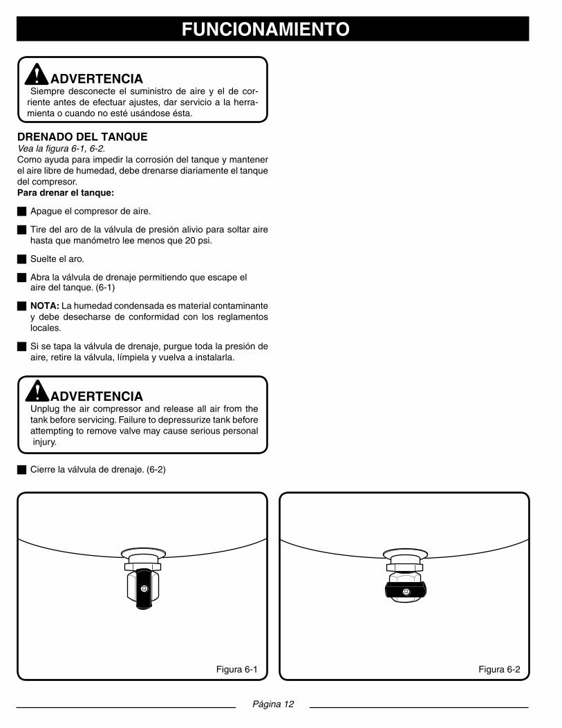
Página 12
FUNCIONAMIENTO
ADVERTENCIASiempredesconecteel suministrodeaire yel de cor-rienteantesdeefectuarajustes,darservicioalaherra-mientaocuandonoestéusándoseésta.
DRENADO DEL TANQUEVea la figura 6-1, 6-2.Comoayudaparaimpedirlacorrosióndeltanqueymantenerelairelibredehumedad,debedrenarsediariamenteeltanquedelcompresor.Para drenar el tanque:
gApagueelcompresordeaire.
gTiredelarodelaválvuladepresiónalivioparasoltaraire hastaquemanómetroleemenosque20psi.
gSuelteelaro.
gAbralaválvuladedrenajepermitiendoqueescapeel airedeltanque.(6-1)
g NOTA:Lahumedadcondensadaesmaterialcontaminante y debe desecharse de conformidad con los reglamentos locales.
gSisetapalaválvuladedrenaje,purguetodalapresiónde aire,retirelaválvula,límpielayvuelvaainstalarla.
ADVERTENCIAUnplug theaircompressorandreleaseallair fromthe tankbeforeservicing.Failuretodepressurizetankbeforeattemptingtoremovevalvemaycauseseriouspersonalinjury.
gCierrelaválvuladedrenaje.(6-2)
Figura6-2Figura6-1

REVISIÓN DE LA VÁLVULA DE PRESIÓN ALIVIOVea las figuras 7-8.
PELIGRO No intente forzar o alterar la válvula de presión alivio.Cualquier pieza floja de este dispositivo puede volar ygolpearlo. La inobservancia de esta advertencia podría causar lesiones serias, e incluso la muerte.
La válvula de presión alivio está diseñada para soltaraireautomáticamentesilapresióndelaparatoreceptordelairesobrepasael límitemáximoprefijado.Debere-visarselaválvulacadadíaantesdeusarlaunidad;paraello, tire del aro con la mano.g Encienda el compresor y permita que se llene el tanque. El compresor se apaga cuando la presión alcanza el límite máximoprefijado.g Apague el compresor.gTiredelarodelaválvuladepresiónalivioparasoltaraire durante tres o cinco segundos. g Suelte el aro. Al soltar el aro, el aire debe dejar de salir de inmediato. Cualquier pérdida de aire que permanezca despuésdesoltarseelarodelaválvuladepresiónalivio indica un problema en ésta. Interrumpa el uso de la unidad permita que se dé servicio a la misma antes de volver a usar el compresor. ADVERTENCIASisefugaairedespuésdesoltarelaro,osiestápegadalaválvulaynopuedeaccionarseconelaro,noutiliceelcompresordeaire,sinohastahaberreemplazadolavál-vula. Utilizar el compresor de aire en estas condiciones puede producir lesiones serias.
PROTECCIÓN CONTRA SOBRECARGA TÉRMICAEstecompresorestáequipadoconunprotectorcontrasobre-cargatérmicaqueapagaráelmotorsiserecalienta.SielprotectorcontrasobrecargasAPAGAfrecuentementeelmotor, busque las causas siguientes.BajovoltajeFalta de ventilación apropiada / temperatura ambiente demasiado altaCalibre de alambre o longitud del cordón de extensión incorrectos Para reajustar el compresor de aire:
g Apague el compresor de aire.g Desconecteelcompresordeairyesperehastaque compresor se enfríe.g Enchufe el compresor de aire en una toma de corriente aprobada.g Encienda el compresor de aire.
VÁVÁLVULA DE PRESIóN ALIVIO
ANILLO
PARA ALIVIO AIRE
Página 13
FUNCIONAMIENTO
Figura7VÁVÁLVULA DE
PRESIóN ALIVIO
Figura8

ADVERTENCIA Al dar servicio a la unidad, sólo utilice piezas de repuesto Husky idénticas. El empleo de piezas diferentes puede causar un peligro o dañar el producto.
ADVERTENCIA
Siempre use gafas de seguridad o anteojos protectores con protección lateral al usar herramientas eléctricas o al soplar el polvo con aire comprimido. Si la operación gen-era mucho polvo, también póngase una mascarilla contra el polvo.
ADVERTENCIA Siempre purgue toda la presión, desconecte la unidad del suministro de corriente y permita que se enfríe antes de limpiarla o efectuarle reparaciones.
MANTENIMIENTO GENERALLa humedad del aire causa se condensa en el tanque. Esta humedad condensada debe drenarse diariamente y/o cada hora siguiendo las instrucciones encontradas en el apartado Drenadodeltanque.La válvula de presión alivio está diseñada para soltar aireautomáticamente si la presión del aparato receptor del airesobrepasa el límite máximo prefijado. Revise la válvula depresión alivio cada vez antes de usar la unidad siguiendo las instruccionesindicadasenelapartadoRevisióndelaválvulade presión alivio.Inspeccione anualmente el tanque para ver si tiene herrum-bre, picaduras u otras imperfecciones que pudieran afectar la seguridad de la unidad.Eviteelempleodesolventesallimpiarpiezasdeplástico.Lamayoríade losplásticossonsusceptiblesadiferentes tiposde solventes comerciales y pueden resultar dañados. Utilice paños limpios para eliminar la suciedad, el polvo, el aceite, la grasa, etc.
ADVERTENCIADonotatanytimeletbrakefluids,gasoline,petroleum- based products, penetrating oils, etc., come in contact with plastic parts. Chemicals can damage, weaken or destroy plastic which may result in serious personal injury.Electrictoolsusedonfiberglassmaterial,wallboard, spackling compounds, or plaster are subject to accelerated wearandpossibleprematurefailurebecausethefiberglass chips and grindings are highly abrasive to bearings, brushes, commutators, etc. Consequently, we do not recommended using this tool for extended work on these types of materials. However, if you do work with any of these materials, it is extremely important to clean the tool using compressed air.
LUBRICACIÓNTodosloscojinetesdeestaherramientaestánlubricadosconsuficientecantidaddeaceitedealtacalidadparatodalavidaútil de launidadencondicionesnormalesde funcionamien-to. Por lo tanto, no se necesita lubricación adicional de los cojinetes.
LIMPIEZA DEL FILTRO DE AIREVea la figura 9.
Cadaciertotiempo,sedeberetirarylimpiarelfiltrodeaire.
gApague el compresor de aire.
g Desconecteelcompresordeaire.
g Gire la cubierta del filtro de aire hacia la izquierda para retirarla.
g Retireelfiltrodeairedelalojamientodelfiltrodeaire.
g Haga pasar el aire comprimido a través del filtro de aire durante10-15segundos.
ALMACENAMIENTO1.Dreneeltanqueparaeliminarlahumedad.
2. Cuando el compresor no se esté utilizando, almacénelo en un lugar fresco y seco.
3.Desconectelamangueraycuelguelosextremosabiertos orientados hacia abajo para permitir el drenaje de la humedad.
4.Enrolle el cable de alimentación en el mango.
Página 14
MANTENIMIENTO
Figura9

ASAMBLEA DE AIR TOOLApliqueCintaselladoraparalasconexionesroscadasde1/4”NPT Conector macho, conectar el Conector macho de la tu-beríaconunallave(llaveinglesay1/4”NPTConectormachonoseproporcionan).Garantizarreguladordelcompresorseajustaalaposicióndemínimo, si se utiliza un compresor y garantizar la presión de salidaestácercadecero.Enchufar 1/4”NPTConectormachode laherramientaparaponerfinamujermayordemangueradeaire.
LUBRICATIÓN DE AIR TOOLLlavedeimpactode1/2”Las llaves de impacto requieren lubricación constantemente y deben ser lubricadas en dos áreas diferentes: el motorneumáticoyelmecanismode impacto.Siga losprocedimien-tos descritos a continuación y vea la descripción de la herra-mienta en el manual derepuestos.
ADVERTENCIA Desconectelallavedeimpactodelafuentedeaire antes de lubricarla.
LUBRICACION DEL MOTOR NEUMATICOEl motor debe ser lubricado diariamente. Este tipo de motor nuncaserálubricadoenexceso.1.Desconectelallavedeimpactodelafuentedeaire.2.Voltéelademodoquelaentradadeaireestéhaciaarriba.3.Oprimaelgatilloyviertaaproximadamente7,4ml(1/4onza) deaceiteparaherramientasneumáticasen laentradade aire.Después,muevaelbotónparacambiarelsentidoen ambas direcciones.4.Conectelallavedeimpactoalafuentedeaireycubrael orificiodesalidaconuna toalla (Vea ladescripciónde la herramientaenelmanualderepuestos).Hagafuncionarla llavedeimpactoenambasdireccionesporunos20sa30s. Saldráaceiteporelorificiodesalidaalaplicarlepresiónde aire.
ADVERTENCIA Despuésqueunaherramientaneumáticahasido l ubricada expulsará aceite por el orificio de salida durante los primeros segundos de funcionamiento. Por lo tanto, DEBERA CUBRIR EL ORIFICIO DE SALIDACONUNATOALLAantesdeaplicarpresión de aire. DE LO CONTRARIO, PODRIA OCASION ARLEHERIDASGRAVES.
LUBRICACION DEL MECANISMO DEIMPACTOLubriqueelmecanismodeimpactomensualmente.Vealapá-gina amarilla adjunta.1.Desconectelallavedeimpactodelafuentedeaire.2.Saqueeltornilloplanootipoallendelorificiodelubricación (Vea ladescripciónde laherramientaenelmanualdere puestos).3.Añádaleaproximadamente29,6ml(1onza)deaceitepara herramientasneumáticasenelorificiodelubricación.Cólo quele el tornillo.4.Reconectelafuentedeairealallavedeimpactoydéjela funcionarpor20sa30s.Lubrique todoelmecanismode impacto volteando la herramienta en todos los sentidos mientras que la herramienta esté funcionando.5.Quíteleeltornillo,sostengalaherramientasobreunenvase adecuado y drene el exceso de aceite. Algunas veces, opri mirel gatillo, cuandoestávaciandoel aceite, leayudaa expulsar el exceso de aceite.6.Sielaceiteestásucio,repitaelprocedimientoanteriorhasta que el aceite salga limpio. Coloque el tornillo y apriételo. Elresiduodeaceitequequedeenlacámaradelmecanismo de impacto es todo lo que se necesita para una lubricación adecuada.
Llavedetrinquetede3/8”Esta herramienta requiere lubricación antes de usarse por pri-mera vez y antes y después de cada uso adicional.1.Desconecteelabastecimientodeaire.2.Viertacercade1/4decucharaditadetédeaceiteparaher ramientasneumáticasenlaentradadeaire.3.Hagafuncionarelgatilloparapermitirqueelaceiteingrese almotorneumático.4.Conectelaherramientaneumáticaalafuentedesuministro deaireycúbraleelorificiodesalidaconunatoalla.Deje que la herramienta neumática funcione de 7s a 10s. Al aplicarle presión de aire la herramienta expulsará aceite porelorificiodesalida.
UTILIZACIÓN DE LA HERRAMIENTA NEUMÁTICAModelo No. F2S26VWDVP
Página 15

Página 16
SOLUCIÓN DE PROBLEMASPROBLEMA CAUSA POSIBLE SOLUCIÓN
El compresor no arranca Recalentamientoopérdidadepotencia
No hay corriente eléctrica
Fusiblefundidoeneltallerocasa
Disyuntorabiertoeneltallerocasa
La sobrecarga térmica es accionada
Interruptor de presión defectuoso
El compresor alcanzó la presión de corte au-tomático
Verifiquecordóndeextensiónestéusándosedeforma correcta
Reviseparaasegurarsedequeestéconectadala unidad
Revise fusible,disyuntoroprotectorcontraso-brecarga térmica
ReemplaceelfusiblefundidodeltallerRestablezcaeldisyuntordeltallerocasa,yde-termine la causa del problema
Consultelapágina13delmanual.
Lleve el compresor a un centro de servicio
Libere aire del tanque hasta que el compresor se reinicieautomáticamente.
El motor zumba pero no funciona o lo hace con lentitud
Voltajebajo
Cordón de extensión de calibre o longitud equiv-ocados
Eldevanadodelmotortienecortooestáabierto
Válvuladeretenciónodeseguridaddefectuosa
Llame a un electricista
Verifique que el calibre y la longitud del cablesean los correctos
Lleve el compresor a un centro de servicio
Lleve el compresor a un centro de servicioLos fusibles se funden o el disyuntor del circuito se dispara continuamente
Fusibledecapacidadincorrecta,sobrecargaenel circuito
Cordón de extensión de calibre o longitud equiv-ocados
Válvuladeretenciónodeseguridaddefectuosa
Verifique que el fusible sea de la capacidadcorrecta, use un fusible con retardo de tiempo, desconecte otros aparatos eléctricos del circuito o conecte el compresor a un subcircuito exclu-sivo
Verifique que el calibre y la longitud del cablesean los correctos
Lleve el compresor a un centro de servicioEl protector contra sobrecarga térmica se activa repetidamente
Voltajebajo
Ventilacióninsuficiente/temperaturaambientaldemasiado elevada
Cordón de extensión de calibre o longitud equiv-ocados
Llame a un electricista
Lleve el compresor a un lugar bien ventilado
Verifique que el calibre y la longitud del cablesean los correctos
La presión del aparato receptor del aire de-sciende cuando se apaga el compresor
Conexiones flojas (adaptadores, mangueras,etc.)
Válvuladedrenajefloja
Reviseparaversihayfugasenlaválvula
Revise todas las conexiones con solución deagua y jabón, y apriételas
Aprietelaválvuladedrenaje
Lleve el compresor a un centro de servicioHumedad excesiva en el aire de descarga Excesiva del agua en el aire del tanque
Alta humedad
Dreneeltanque
Lleve la unidad a un lugar de menor humedad; useunfiltrodeaireenlínea
El compresor funciona continuamente Interruptor de presión defectuoso
Uso excesivo de aire
Lleve el compresor a un centro de servicio
Disminuyaelconsumodeaire;elcompresornoes de la suficiente capacidad para las necesi-dades de la herramienta
El compresor vibra Aflojelospernosdemontaje Apriete los pernos de montaje
Produccióndeairemásbajadelonormal Válvulasdeentradadescompuestas
Hay conexiones con fugas
Lleve el compresor a un centro de servicio
Apriete las conexiones

DIAGRAMA DE LOS COMPONENTES
Página 17
1
3
4
5
2
67
89
1011
1213
14
8
15
16
18
17
70
19 22
21
24
2526
27 282930
232032
33
34
35
36
37
38
39
40
4142
43
45
44
46
47
48
49 50
5152
54
56
57
58
53
55
60
61
62
63
64
65
66
67
31
59
68
69
7172

Página 18
LISTA DE LAS PIEZAS - Modelo #671-049
# de ref.
Juego #
Númerode pieza Descripción Cantidad
# dejuego
# depieza Nombre del juego # de referencia
1 E100794 Juegodelfiltrodeaire 68-702 E103497 Juegodeconjuntodeplacadeválvula 7-153 E104441 Juegodeexcéntricaycojinete 19-214 E103495 Juegodelpistón 22-275 E104280 Juegodeventilador 28-306 E104442 Juegoderuedade7pulgadas 41-44 (unensamblajederuedacon piezasincorporadas) 7 E104440 Juegodebomba/motor 5,6-30,71-72
# de ref.
Juego #
Númerode pieza Descripción Cantidad
1 E103985 Cubiertasuperior 12 7 Ensamblaje del motor 1 (disponiblesolamenteen eljuegoE104440)3 E100329 PernoM8x1.25x16mm 44 E100524 Arandeladeseguridad8mm 45 E100570 Arandelaplana8mm 46 4,7 Cilindro 17 2,7 Anillotóricodelcilindro 18 2,7 PernoM3x0.4x5mm,HFH 29 2,7 Válvula,Retenedor,Admisión 110 2,7 Válvula,Admisión 111 2,7 Placadeválvula 112 2,7 Válvuladesalida 113 2,7 Válvula,Retenedor,Salida 114 2,7 Arandeladeseguridad3mm 115 2,7 Anillotóricodelacabeza 116 7 E100284 Cabeza,Cilindro 117 7 E100709 Arandelaplan6mm 418 7 E100427 PernoM6x1x35mmSHC 419 3,7 Excéntrica 120 7 E100427 PernoM6x1x35mmSHC 121 3,7 Cojinete, Pistón 122 3,7 Tuerca,M5x0.8 123 5,7 Arandelaplan6mm 124 4,7 Tornillo,M5x0.8x16mmSHC 125 4,7 Tapa del pistón 126 4,7 Sello del pistón 127 4,7 Pistón 128 5,7 Ventilador 1 Tornillo de cabeza hueca de rosca 29 5,7 Arandelaplan6mm 130 5,7 PernoM6x1x16mm 131 E101790 Cabledealimentación 132 E104134 Tubería,Múltiple, 1 Trenzado en acero 33 E103984 Filtros,rejilladeventilación 234 E103986 Cubiertaprotectora,Baja 135 E101362 Válvula,deretención,90°,izquierda 136 Ensamblaje de tanque 137 E100242 Tuerca,M8x1.25 238 E100570 ArandelaplanaM8 2
39 E100240 Aislador,Ronda 240 E100225 PernoM8x1,25x30mm 241 6 PernoderesaltoM10x1,25 2 x39mmHH 42 6 Ruedade7pulgadas 243 6 Válvuladedrenaje,1/4 244 6 ArandelaplanaM10 245 E101717 TuercadeseguridadM10x1.25 146 E103982 Mango 147 E100524 ArandeladeseguridadM8 448 E100602 PernoM8x1.25x25mmHFHS 449 E104137 Manguera,Múltiple, 1 Trenzado en acero 50 E104136 Tubodealivio(nylon) 151 E102622 Tornillo,#8x25mmPlastite® 752 E104000 Accionador,interruptor 153 E103987 Bushing,Cord 154 E102026 Codo,90˚,1/4MNPTx1/4MNPT 155 E104135 Interruptordepresión, 1 desconexióna150psi56 E102612 Válvuladeseguridad,165psi 157 E103996 Acopladorde1/4FNPTx 1 1/4FNPTx20mm 58 E104335 Niplede1/4MNPTx 2 1/4MNPTx40mm 59 E100793 Empuñaduradelmango 160 E102822 Acopladordeconexiónrápida 261 E103980 Múltipleconregulador 162 E101757 Tapónde1/4NPT 163 E103744 Manómetro, 2 pulgadas, línea 2 rojaa150PSI,entradanegra64 E103981 Soporte, Interior 165 E100792 ArandelaplanM6 266 E100713 PernoM6x1.0x16mm 267 E102531 Tornillo,M6x1x12HFH 268 1 Basedelfiltrodeaire 169 1 E100435 Elementodelfiltrodeaire 170 1 Tapadelfiltrodeaire 171 E104272 Capacitor de arranque 172 E104273 Capacitor de funcionamiento 1
Nota:Loscamposdenúmerodepiezasinnúmeroindicadonoestándisponibles.
Las descripciones se ofrecen sólo como referencia.

Página 19
GARANTÍA
DECLARACIÓN DE LA GARANTÍA LIMITADAMAT Holdings, Inc. garantiza al comprador original al menu-deo que este producto de MAT Holdings, Inc. carece de de-fectos en los materiales y mano de obra y acuerda reparar o reemplazar, a la sola discreción de MAT Holdings, Inc., cualquier producto defectuoso sin cargo alguno dentro del plazoestablecidodespuésdelafechadecompra:g Un año si el producto se emplea para uso personal, familiar o doméstico;g 90 días si el producto se emplea para cualquier otro propósito, como el uso comercial o el de alquiler.Estagarantíaúnicamente seofreceal compradororiginalal menudeo y comienza en la fecha de la compra original al menudeo.Cualquier parte del producto MAT Holdings, Inc. manufac-turado o suministrado por MAT Holdings, Inc. que, a juicio razonable de MAT Holdings, Inc. tenga defectos en los ma-terialesoenlamanodeobra,seráreparadooremplazadopor un establecimiento de servicio autorizado de productos MAT Holdings, Inc. , sin cargo alguno al comprador por con-cepto de piezas y mano de obra.El producto, incluida toda pieza defectuosa, debe enviarse a un establecimiento de servicio autorizado dentro del período de la garantía. El propietario es responsable de pagar los gastos de entrega del producto MAT Holdings, Inc. al es-tablecimiento para cualquier trabajo garantizado y también los gastos de devolución de la pieza al propietario después de la reparación o reemplazo. La responsabilidad de MAT Holdings, Inc.’s con respecto a todo reclamo se limita a las reparacionesoremplazodelproducto,yningúnreclamodeincumplimientode lagarantíaserácausantede lacancel-aciónorescisióndelcontratodeventadeningúnproductodeMATHoldings, Inc. En el establecimiento se requeriráel recibo de compra para respaldar cualquier reclamo al amparo de la garantía. Todo trabajo cubierto en la garantía debe ser realizado por un concesionario de servicio autor-izado de MAT Holdings, Inc.Estagarantíaselimitaanoventa(90)díasapartirdelafechaoriginal de la compra de cualquier producto MAT Holdings, Inc. empleado para propósitos comerciales o de alquiler, o cualquier otro propósito generador de ingresos.EstagarantíanocubreningúnproductodeMATHoldings,Inc. que haya estado sujeto a abuso, abandono, negligencia o accidente, o que se haya utilizado en alguna manera de formacontrariaalasinstruccionesdefuncionamientosegúnseespecificaenestemanualdeloperador.Estagarantíano aplica a los daños en el producto de MAT Holdings, Inc. que resulten de un mantenimiento indebido ni a producto al-guno de MAT Holdings, Inc. que haya sido alterado o modi-ficado.Lagarantíanocubrelasreparacionesqueresultennecesarias por el desgaste normal o por el uso de piezas o accesorios que sean incompatibles con el producto de Mat Holdings, Inc. o que afecten adversamente su funciona-
miento, desempeño o durabilidad.MAT Holdings, Inc. se reserva el derecho a cambiar o me-jorar el diseño de cualquier producto de MAT Holdings, Inc. sinasumirningunaobligacióndemodificarningúnproductofabricado previamente.TODASLASGARANTÍASIMPLÍCITASESTÁNLIMITADASENDURACIÓNSEGÚNELPERÍODODEGARANTÍADE-CLARADA.PORCONSIGUIENTE,CUALQUIERGARANTÍAIMPLÍCITA, INCLUSOLASDECOMERCIABILIDAD,IDO-NEIDADPARAUNPROPÓSITOENPARTICULAR,ODECUALQUIERTIPO,PIERDENTOTALMENTESUVALIDEZDESPUÉS DEL VENCIMIENTO DEL PERÍODO DE GA-RANTÍACORRESPONDIENTEDEDOSAÑOS,UNAÑOONOVENTADÍAS.DECONFORMIDADCONESTAGA-RANTÍA,LAOBLIGACIÓNDEMATHoldings,Inc.,SELIM-ITAESTRICTAYEXCLUSIVAMENTEALAREPARACIÓNOREMPLAZODELASPIEZASDEFECTUOSAS,YMATHoldings,Inc.,NOASUMENINGUNAOTRAOBLIGACIÓN,NIAUTORIZAANADIEASUMIRLAANOMBREDEDICHACOMPAÑÍA.ALGUNOS ESTADOS NO PERMITEN LIMI-TACIONESENCUANTOA LADURACIÓNDEUNAGA-RANTÍAIMPLÍCITA,PORLOCUALESPOSIBLEQUELALIMITACIÓNANTERIORNOSEAPLIQUEENELCASODEUSTED.MATHoldings,Inc.NOASUMENINGUNARE-SPONSABILIDADPORDAÑOSDIRECTOS,INDIRECTOSODENINGÚNOTROTIPO,COMOELGASTODEEN-VIARELPRODUCTODEMATHoldings,Inc.AUNESTA-BLECIMIENTODESERVICIOAUTORIZADOYELGASTODE ENVIARLO DEALLÍAL PROPIETARIO, EL TIEMPODEVIAJEDELMECÁNICO,CARGOSTELEFÓNICOSOTELEGRÁFICOS, ALQUILER DE UN PRODUCTO SUS-TITUTO DURANTE EL TIEMPO DE REALIZACIÓN DELSERVICIODE LAGARANTÍA, VIAJES, PÉRDIDAODA-ÑOSAOBJETOSDEPROPIEDADPERSONAL,PÉRDIDADE INGRESOS, PÉRDIDA DEL USO DEL PRODUCTO,PÉRDIDADETIEMPOO INCONVENIENTES.ENALGU-NOSESTADOSNOSEPERMITELAEXCLUSIÓNOLIMI-TACIÓNDEDAÑOSDIRECTOSOINDIRECTOS,PORLOCUALESPOSIBLEQUELALIMITACIÓNOEXCLUSIÓNDESCRITAARRIBANOSEAPLIQUEENSUCASO.Esta garantía le confiere derechos legales específicos, yes posible que usted goce de otros derechos, los cuales pueden variar de estado a estado.Esta garantía se aplica a todos los productos de MAT Hold-ings, Inc. fabricados o vendidos por dicha compañía en Es-tadosUnidosyCanadá.Paraencontrarelconcesionariodeservicioautorizadomáscercano a used, llame al 1-888-859-4549

Página 20
NOTAS