Embed Size (px)
Citation preview
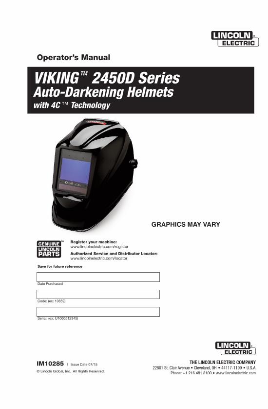
GRAPHICS MAY VARY
Operator’s Manual
Register your machine: www.lincolnelectric.com/register
Authorized Service and Distributor Locator: www.lincolnelectric.com/locator
IM10285 | Issue D ate 07/15
© Lincoln Global, Inc. All Rights Reserved.
Save for future reference
Date Purchased
Code: (ex: 10859)
Serial: (ex: U1060512345)
VIKING TM 2450D Series Auto-Darkening Helmetswith 4C ™ Technology
TABLE OF CONTENTS Page
SAFETY WARNINGS – READ BEFORE USING 1
HELMET INFORMATION 2
SPECIFICATIONS 3
OPERATING INSTRUCTIONS 4
CARTRIDGE OPERATIONS/FEATURES 5 thru 7
HELMET CARE AND MAINTENANCE 8
SHADE GUIDE SETTINGS 8
CARTRIDGE AND LENS REPLACEMENT 9
TROUBLESHOOTING 10
WARRANTY INFORMATION 11
REPLACEMENT PARTS 11
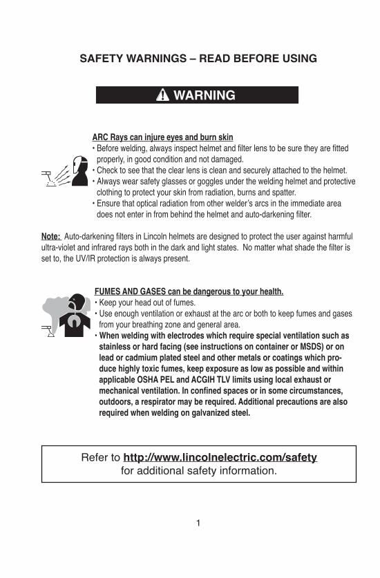
SAFETY WARNINGS – READ BEFORE USING
ARC Rays can injure eyes and burn skin• Before welding, always inspect helmet and filter lens to be sure they are fitted
properly, in good condition and not damaged.• Check to see that the clear lens is clean and securely attached to the helmet.• Always wear safety glasses or goggles under the welding helmet and protective
clothing to protect your skin from radiation, burns and spatter.• Ensure that optical radiation from other welder’s arcs in the immediate area
does not enter in from behind the helmet and auto-darkening filter.
Note: Auto-darkening filters in Lincoln helmets are designed to protect the user against harmfulultra-violet and infrared rays both in the dark and light states. No matter what shade the filter isset to, the UV/IR protection is always present.
FUMES AND GASES can be dangerous to your health.• Keep your head out of fumes.• Use enough ventilation or exhaust at the arc or both to keep fumes and gases
from your breathing zone and general area.• When welding with electrodes which require special ventilation such as
stainless or hard facing (see instructions on container or MSDS) or onlead or cadmium plated steel and other metals or coatings which pro-duce highly toxic fumes, keep exposure as low as possible and withinapplicable OSHA PEL and ACGIH TLV limits using local exhaust ormechanical ventilation. In confined spaces or in some circumstances,outdoors, a respirator may be required. Additional precautions are alsorequired when welding on galvanized steel.
1
WARNING
Refer to http://www.lincolnelectric.com/safetyfor additional safety information.
HELMET INFORMATION
This Auto-Darkening Welding Helmet will change from a light state (shade 4)to a dark state (Shade 5-13) when arc welding starts.
The filter automatically returns to a light state when the arc stops.
Match your welding application to the shade indicated on the shade chart.(See Page 8)
• Operating temperature: 14°F ~ 131°F (-10°C ~ 55°C).• Do not use or open the auto-darkening filter if damaged by shock,
vibration or pressure.• Keep the sensors and solar cell clean. Clean the filter cartridge using a
soapy water solution and soft cloth which should be damp but not saturated.
This Auto-Darkening Welding Helmet is designed for use with GMAW, GTAW,MMAW welding, or Plasma Arc and air carbon arc cutting. This helmet alsohas cutting and grinding modes.
The cartridge provides protection from harmful UV and IR radiation, in bothdark and light states.
The cartridge contains four sensors to detect the light from the welding arc,resulting in the lens darkening to a selected welding shade.
• Do not use solvents or abrasive cleaning detergent.• If cover lens is spattered or covered with dirt, it should be replaced
immediately.• Use only replacement parts specified in this manual.• Do not use the helmet without inside and outside cover lenses properly
installed.
• Do not use helmet if lens does not function as described.
2
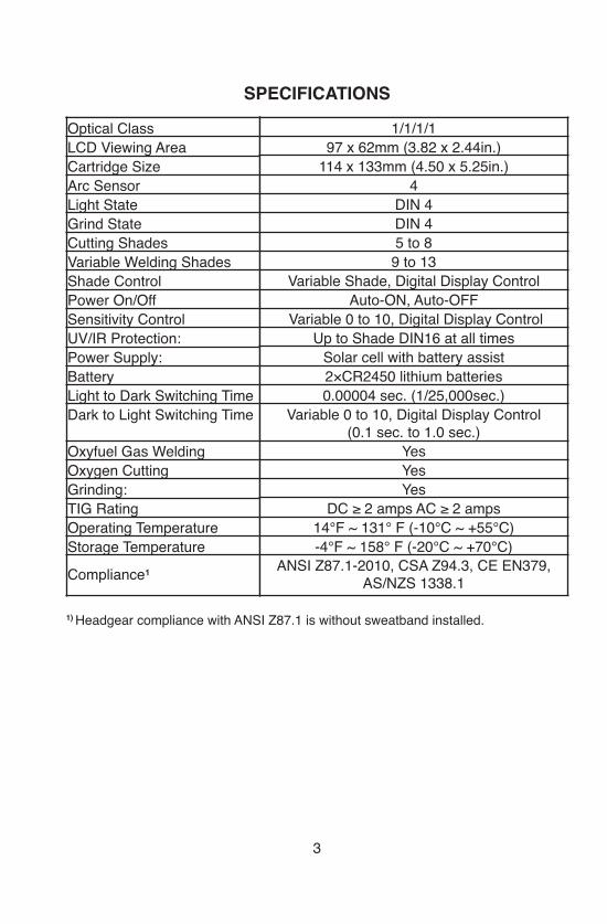
SPECIFICATIONS
1) Headgear compliance with ANSI Z87.1 is without sweatband installed.
3
Optical ClassLCD Viewing AreaCartridge SizeArc SensorLight StateGrind StateCutting ShadesVariable Welding ShadesShade ControlPower On/OffSensitivity ControlUV/IR Protection: Power Supply: BatteryLight to Dark Switching Time Dark to Light Switching Time
Oxyfuel Gas Welding Oxygen Cutting Grinding: TIG RatingOperating TemperatureStorage TemperatureCompliance¹
1/1/1/197 x 62mm (3.82 x 2.44in.)
114 x 133mm (4.50 x 5.25in.)4
DIN 4DIN 45 to 8
9 to 13Variable Shade, Digital Display Control
Auto-ON, Auto-OFFVariable 0 to 10, Digital Display Control
Up to Shade DIN16 at all timesSolar cell with battery assist 2×CR2450 lithium batteries 0.00004 sec. (1/25,000sec.)
Variable 0 to 10, Digital Display Control(0.1 sec. to 1.0 sec.)
YesYesYes
DC ≥ 2 amps AC ≥ 2 amps14°F ~ 131° F (-10°C ~ +55°C)-4°F ~ 158° F (-20°C ~ +70°C)
ANSI Z87.1-2010, CSA Z94.3, CE EN379,AS/NZS 1338.1
OPERATING INSTRUCTIONS
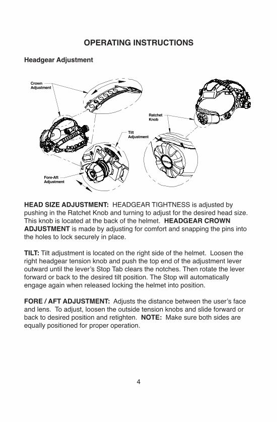
Headgear Adjustment
HEAD SIZE ADJUSTMENT: HEADGEAR TIGHTNESS is adjusted by pushing in the Ratchet Knob and turning to adjust for the desired head size.This knob is located at the back of the helmet. HEADGEAR CROWNADJUSTMENT is made by adjusting for comfort and snapping the pins intothe holes to lock securely in place.
TILT: Tilt adjustment is located on the right side of the helmet. Loosen theright headgear tension knob and push the top end of the adjustment leveroutward until the lever’s Stop Tab clears the notches. Then rotate the leverforward or back to the desired tilt position. The Stop will automaticallyengage again when released locking the helmet into position.
FORE / AFT ADJUSTMENT: Adjusts the distance between the user’s faceand lens. To adjust, loosen the outside tension knobs and slide forward orback to desired position and retighten. NOTE: Make sure both sides areequally positioned for proper operation.
4
CrownAdjustment
RatchetKnob
Fore-AftAdjustment
TiltAdjustment
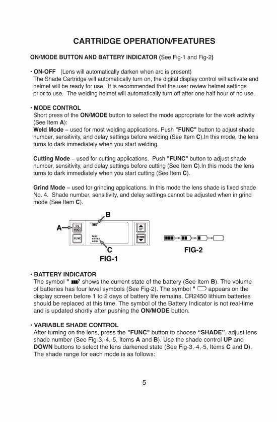
CARTRIDGE OPERATION/FEATURESON/MODE BUTTON AND BATTERY INDICATOR (See Fig-1 and Fig-2)
• ON-OFF (Lens will automatically darken when arc is present)The Shade Cartridge will automatically turn on, the digital display control will activate andhelmet will be ready for use. It is recommended that the user review helmet settingsprior to use. The welding helmet will automatically turn off after one half hour of no use.
• MODE CONTROL Short press of the ON/MODE button to select the mode appropriate for the work activity(See Item A): Weld Mode − used for most welding applications. Push "FUNC" button to adjust shadenumber, sensitivity, and delay settings before welding (See Item C).In this mode, the lensturns to dark immediately when you start welding.
Cutting Mode − used for cutting applications. Push "FUNC" button to adjust shadenumber, sensitivity, and delay settings before cutting (See Item C).In this mode the lensturns to dark immediately when you start cutting (See Item C).
Grind Mode − used for grinding applications. In this mode the lens shade is fixed shadeNo. 4. Shade number, sensitivity, and delay settings cannot be adjusted when in grindmode (See Item C).
• BATTERY INDICATORThe symbol " " shows the current state of the battery (See Item B). The volumeof batteries has four level symbols (See Fig-2). The symbol " " appears on thedisplay screen before 1 to 2 days of battery life remains, CR2450 lithium batteriesshould be replaced at this time. The symbol of the Battery Indicator is not real-timeand is updated shortly after pushing the ON/MODE button.
• VARIABLE SHADE CONTROLAfter turning on the lens, press the "FUNC" button to choose “SHADE”, adjust lensshade number (See Fig-3,-4,-5, Items A and B). Use the shade control UP andDOWN buttons to select the lens darkened state (See Fig-3,-4,-5, Items C and D).The shade range for each mode is as follows:
5
AB
FIG-1FIG-2C
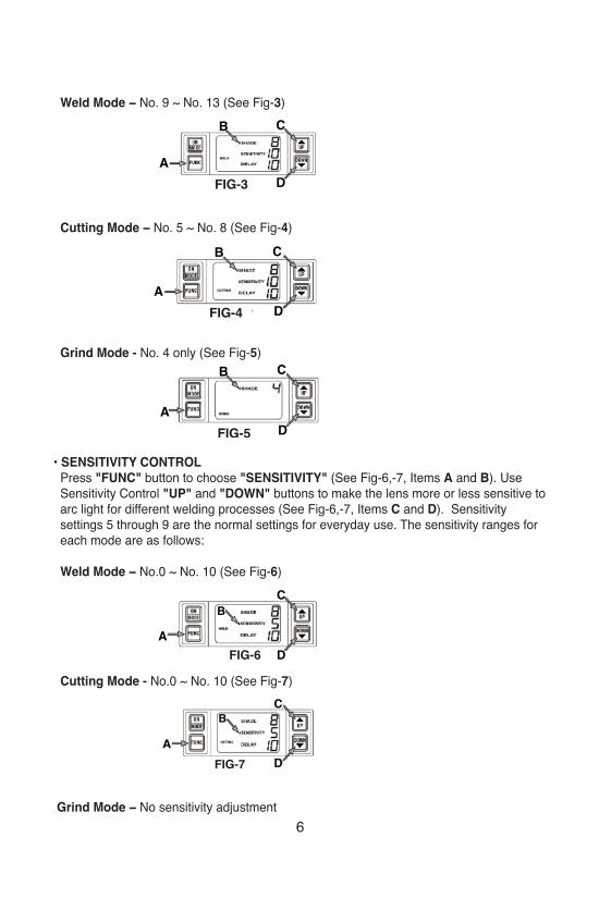
Weld Mode − No. 9 ~ No. 13 (See Fig-3)
Cutting Mode − No. 5 ~ No. 8 (See Fig-4)
Grind Mode - No. 4 only (See Fig-5)
• SENSITIVITY CONTROLPress "FUNC" button to choose "SENSITIVITY" (See Fig-6,-7, Items A and B). UseSensitivity Control "UP" and "DOWN" buttons to make the lens more or less sensitive toarc light for different welding processes (See Fig-6,-7, Items C and D). Sensitivity settings 5 through 9 are the normal settings for everyday use. The sensitivity ranges foreach mode are as follows:
Weld Mode − No.0 ~ No. 10 (See Fig-6)
Cutting Mode - No.0 ~ No. 10 (See Fig-7)
Grind Mode − No sensitivity adjustment 6
A
B C
FIG-3 D
A
B C
FIG-4 D
A
B C
FIG-5 D
AB
C
FIG-6 D
A
BC
FIG-7 D
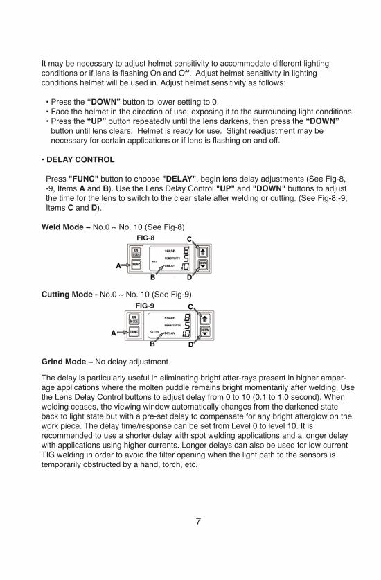
It may be necessary to adjust helmet sensitivity to accommodate different lighting conditions or if lens is flashing On and Off. Adjust helmet sensitivity in lighting conditions helmet will be used in. Adjust helmet sensitivity as follows:
• Press the “DOWN” button to lower setting to 0. • Face the helmet in the direction of use, exposing it to the surrounding light conditions. • Press the “UP” button repeatedly until the lens darkens, then press the “DOWN”
button until lens clears. Helmet is ready for use. Slight readjustment may be necessary for certain applications or if lens is flashing on and off.
• DELAY CONTROL
Press "FUNC" button to choose "DELAY", begin lens delay adjustments (See Fig-8,-9, Items A and B). Use the Lens Delay Control "UP" and "DOWN" buttons to adjustthe time for the lens to switch to the clear state after welding or cutting. (See Fig-8,-9,Items C and D).
Weld Mode − No.0 ~ No. 10 (See Fig-8)
Cutting Mode - No.0 ~ No. 10 (See Fig-9)
Grind Mode − No delay adjustment
The delay is particularly useful in eliminating bright after-rays present in higher amper-age applications where the molten puddle remains bright momentarily after welding. Usethe Lens Delay Control buttons to adjust delay from 0 to 10 (0.1 to 1.0 second). Whenwelding ceases, the viewing window automatically changes from the darkened stateback to light state but with a pre-set delay to compensate for any bright afterglow on thework piece. The delay time/response can be set from Level 0 to level 10. It is recommended to use a shorter delay with spot welding applications and a longer delaywith applications using higher currents. Longer delays can also be used for low currentTIG welding in order to avoid the filter opening when the light path to the sensors is temporarily obstructed by a hand, torch, etc.
7
AB
CFIG-8
D
AB
CFIG-9
D
HELMET CARE AND MAINTENANCE
Cleaning: Clean helmet by wiping with a soft cloth. Clean cartridge surfacesregularly. Do not use strong cleaning solutions. Clean sensors and solar cellswith soapy water solution and a clean cloth and wipe dry with a lint-free cloth.Do NOT submerge shade cartridge in water or other solution.
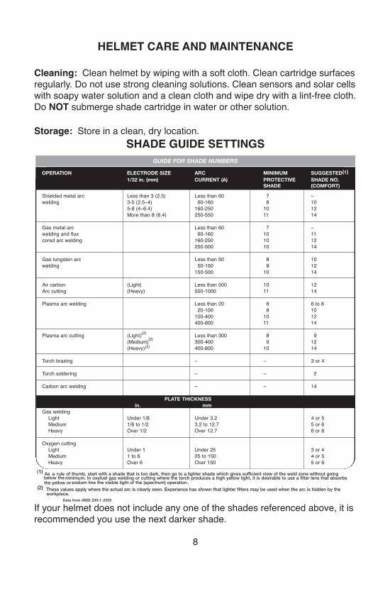
Storage: Store in a clean, dry location.SHADE GUIDE SETTINGS
If your helmet does not include any one of the shades referenced above, it isrecommended you use the next darker shade.
8
NT 1
GUIDE FOR SHADE NUMBERS
OPERATION ELECTRODE SIZE ARC MINIMUM SUGGESTED(1)
1/32 in. (mm) CURRENT (A) PROTECTIVE SHADE NO.SHADE (COMFORT)
Shielded metal arc Less than 3 (2.5) Less than 60 7 –welding 3-5 (2.5–4) 60-160 8 10
5-8 (4–6.4) 160-250 10 12More than 8 (6.4) 250-550 11 14
Gas metal arc Less than 60 7 –welding and flux 60-160 10 11cored arc welding 160-250 10 12
250-500 10 14
Gas tungsten arc Less than 50 8 10welding 50-150 8 12
150-500 10 14
Air carbon (Light) Less than 500 10 12Arc cutting (Heavy) 500-1000 11 14
Plasma arc welding Less than 20 6 6 to 820-100 8 10100-400 10 12400-800 11 14
Plasma arc cutting (Light)(2)
(2)
(2) Less than 300 8 9(Medium) 300-400 9 12(Heavy) 400-800 10 14
Torch brazing – – 3 or 4
Torch soldering – – 2
Carbon arc welding – – 14
PLATE THICKNESSin. mm
Gas weldingLight Under 1/8 Under 3.2 4 or 5Medium 1/8 to 1/2 3.2 to 12.7 5 or 6Heavy Over 1/2 Over 12.7 6 or 8
Oxygen cuttingLight Under 1 Under 25 3 or 4Medium 1 to 6 25 to 150 4 or 5Heavy Over 6 Over 150 5 or 6
(1) As a rule of thumb, start with a shade that is too dark, then go to a lighter shade which gives sufficient view of the weld zone without goingbelow the minimum. In oxyfuel gas welding or cutting where the torch produces a high yellow light, it is desirable to use a filter lens that absorbsthe yellow or sodium line the visible light of the (spectrum) operation
(2) These values apply where the actual arc is clearly seen. Experience has shown that lighter filters may be used when the arc is hidden by theworkpiece.
.
Data from ANSI Z49.1-2005
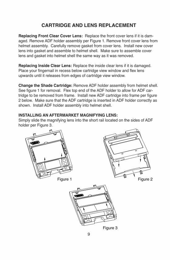
CARTRIDGE AND LENS REPLACEMENT
Replacing Front Clear Cover Lens: Replace the front cover lens if it is dam-aged. Remove ADF holder assembly per Figure 1. Remove front cover lens fromhelmet assembly. Carefully remove gasket from cover lens. Install new coverlens into gasket and assemble to helmet shell. Make sure to assemble coverlens and gasket into helmet shell the same way as it was removed.
Replacing Inside Clear Lens: Replace the inside clear lens if it is damaged.Place your fingernail in recess below cartridge view window and flex lensupwards until it releases from edges of cartridge view window.
Change the Shade Cartridge: Remove ADF holder assembly from helmet shell.See figure 1 for removal. Flex top end of the ADF holder to allow for ADF car-tridge to be removed from frame. Install new ADF cartridge into frame per figure2 below. Make sure that the ADF cartridge is inserted in ADF holder correctly asshown. Install ADF holder assembly into helmet shell.
INSTALLING AN AFTERMARKET MAGNIFYING LENS:Simply slide the magnifying lens into the short rail located on the sides of ADFholder per Figure 3.
9Figure 3
Figure 1 Figure 2
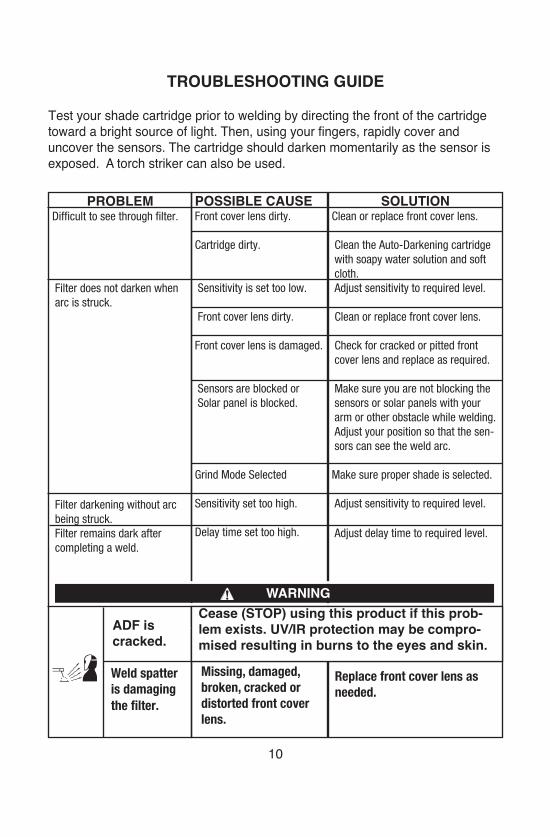
TROUBLESHOOTING GUIDE
Test your shade cartridge prior to welding by directing the front of the cartridgetoward a bright source of light. Then, using your fingers, rapidly cover and uncover the sensors. The cartridge should darken momentarily as the sensor isexposed. A torch striker can also be used.
10
SOLUTIONClean or replace front cover lens.
Clean the Auto-Darkening cartridgewith soapy water solution and softcloth.Adjust sensitivity to required level.
Clean or replace front cover lens.
Check for cracked or pitted frontcover lens and replace as required.
Make sure you are not blocking thesensors or solar panels with yourarm or other obstacle while welding.Adjust your position so that the sen-sors can see the weld arc.
Make sure proper shade is selected.
Adjust sensitivity to required level.
Adjust delay time to required level.
Replace front cover lens asneeded.
POSSIBLE CAUSEFront cover lens dirty.
Cartridge dirty.
Sensitivity is set too low.
Front cover lens dirty.
Front cover lens is damaged.
Sensors are blocked orSolar panel is blocked.
Grind Mode Selected
Sensitivity set too high.
Delay time set too high.
Missing, damaged,broken, cracked ordistorted front coverlens.
PROBLEMDifficult to see through filter.
Filter does not darken whenarc is struck.
Filter darkening without arcbeing struck.Filter remains dark aftercompleting a weld.
ADF iscracked.
Weld spatteris damagingthe filter.
WARNINGCease (STOP) using this product if this prob-lem exists. UV/IR protection may be compro-mised resulting in burns to the eyes and skin.
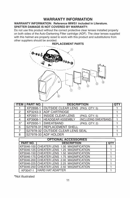
WARRANTY INFORMATIONWARRANTY INFORMATION: Reference IMWS1 included in Literature.SPATTER DAMAGE IS NOT COVERED BY WARRANTY:Do not use this product without the correct protective clear lenses installed properlyon both sides of the Auto-Darkening Filter cartridge (ADF). The clear lenses suppliedwith this helmet are properly sized to work with this product and substitutions fromother suppliers should be avoided.
REPLACEMENT PARTS
*Not illustrated11
32
71
8
6
4
ITEM12345*678
QTY11111111
PART NO.KP2898-1KP3243-3KP2931-1KP3908-1KP2930-1S27978-31S27978-32S27978-33
DESCRIPTIONOUTSIDE CLEAR LENS (PKG. QTY: 5)ADF CARTRIDGEINSIDE CLEAR LENS (PKG. QTY: 5)HEADGEAR ASSEMBLY (INCLUDING SWEATBAND)SWEATBAND (PKG. QTY: 2)REPLACEMENT SHELLOUTSIDE CLEAR LENS SEALADF HOLDER
QTY11111111
PART NO.KP3046-100KP3046-125KP3046-150KP3046-175KP3046-200KP3046-225KP3046-250
KP3047-1
DESCRIPTIONCHEATER LENS 1.00 MAGNIFICATIONCHEATER LENS 1.25 MAGNIFICATIONCHEATER LENS 1.50 MAGNIFICATIONCHEATER LENS 1.75 MAGNIFICATIONCHEATER LENS 2.00 MAGNIFICATIONCHEATER LENS 2.25 MAGNIFICATIONCHEATER LENS 2.50 MAGNIFICATIONHARD HAT ADAPTER
OPTIONAL ACCESSORIES
CUSTOMER ASSISTANCE POLICY
The business of The Lincoln Electric Company is manufacturing andselling high quality welding equipment, consumables, and cuttingequipment. Our challenge is to meet the needs of our customers and toexceed their expectations. On occasion, purchasers may ask Lincoln Electric for advice or information about their use of our products.We respond to our customers based on the best information in ourpossession at that time. Lincoln Electric is not in a position to warrant orguarantee such advice, and assumes no liability, with respect to suchinformation or advice. We expressly disclaim any warranty of any kind,including any warranty of fitness for any customer’s particular purpose,with respect to such information or advice. As a matter of practicalconsideration, we also cannot assume any responsibility for updating orcorrecting any such information or advice once it has been given, nordoes the provision of information or advice create, expand or alter anywarranty with respect to the sale of our products.
Lincoln Electric is a responsive manufacturer, but the selection and use ofspecific products sold by Lincoln Electric is solely within the control of,and remains the sole responsibility of the customer. Many variablesbeyond the control of Lincoln Electric affect the results obtained inapplying these types of fabrication methods and service requirements.
Subject to Change – This information is accurate to the best of ourknowledge at the time of printing. Please refer to www.lincolnelectric.com for any updated information.