Embed Size (px)
Citation preview

Operator’s Manual
Rear-tine Tiller Models 630B—Tuffy®
634F—BroncoTM
634B—Super BroncoTM
Warning: This unit is equipped with an internal combustion engine and should not be used on or near any unimproved forest-covered, brush-cov-ered or grass-covered land unless the engine’s exhaust system is equipped with a spark arrester meeting applicable local or state laws (if any). If aspark arrester is used, it should be maintained in effective working order by the operator. In the State of California the above is required by law(Section 4442 of the California Public Resources Code). Other states may have similar laws. Federal laws apply on federal lands. A spark arresterfor the muffler is available by contacting the service department at Troy-Bilt LLC, P.O. Box 361131 Cleveland, Ohio 44136-0019.
IMPORTANT:READ SAFETY RULES AND INSTRUCTIONS CAREFULLY
TROY-BILT LLC, P.O. BOX 361131, CLEVELAND, OH 44136-0019
PRINTED IN USA FROM NO. 770-10594A(12/2001)
Model 634B Shown
For more details about your unit, visit our website at www.troybilt.com
TABLE OF CONTENTSContent Page
Calling Customer Support . . . . . . . . . . . . . . . . . . . . . . . . . . . . . . . . . . . . . . . . . . . . . . . . . . . . 2
Safety . . . . . . . . . . . . . . . . . . . . . . . . . . . . . . . . . . . . . . . . . . . . . . . . . . . . . . . . . . . . . . . . . . . 3
Assembly. . . . . . . . . . . . . . . . . . . . . . . . . . . . . . . . . . . . . . . . . . . . . . . . . . . . . . . . . . . . . . . . . 6
Features and Controls. . . . . . . . . . . . . . . . . . . . . . . . . . . . . . . . . . . . . . . . . . . . . . . . . . . . . . . 10
Operation . . . . . . . . . . . . . . . . . . . . . . . . . . . . . . . . . . . . . . . . . . . . . . . . . . . . . . . . . . . . . . . . 12
Maintenance . . . . . . . . . . . . . . . . . . . . . . . . . . . . . . . . . . . . . . . . . . . . . . . . . . . . . . . . . . . . . . 17
Off-Season Storage . . . . . . . . . . . . . . . . . . . . . . . . . . . . . . . . . . . . . . . . . . . . . . . . . . . . . . . . 21
Troubleshooting . . . . . . . . . . . . . . . . . . . . . . . . . . . . . . . . . . . . . . . . . . . . . . . . . . . . . . . . . . . 22
Parts List . . . . . . . . . . . . . . . . . . . . . . . . . . . . . . . . . . . . . . . . . . . . . . . . . . . . . . . . . . . . . . . . . 23
Warrany Information . . . . . . . . . . . . . . . . . . . . . . . . . . . . . . . . . . . . . . . . . . . . . . . . . . . . . . . . Back Cover
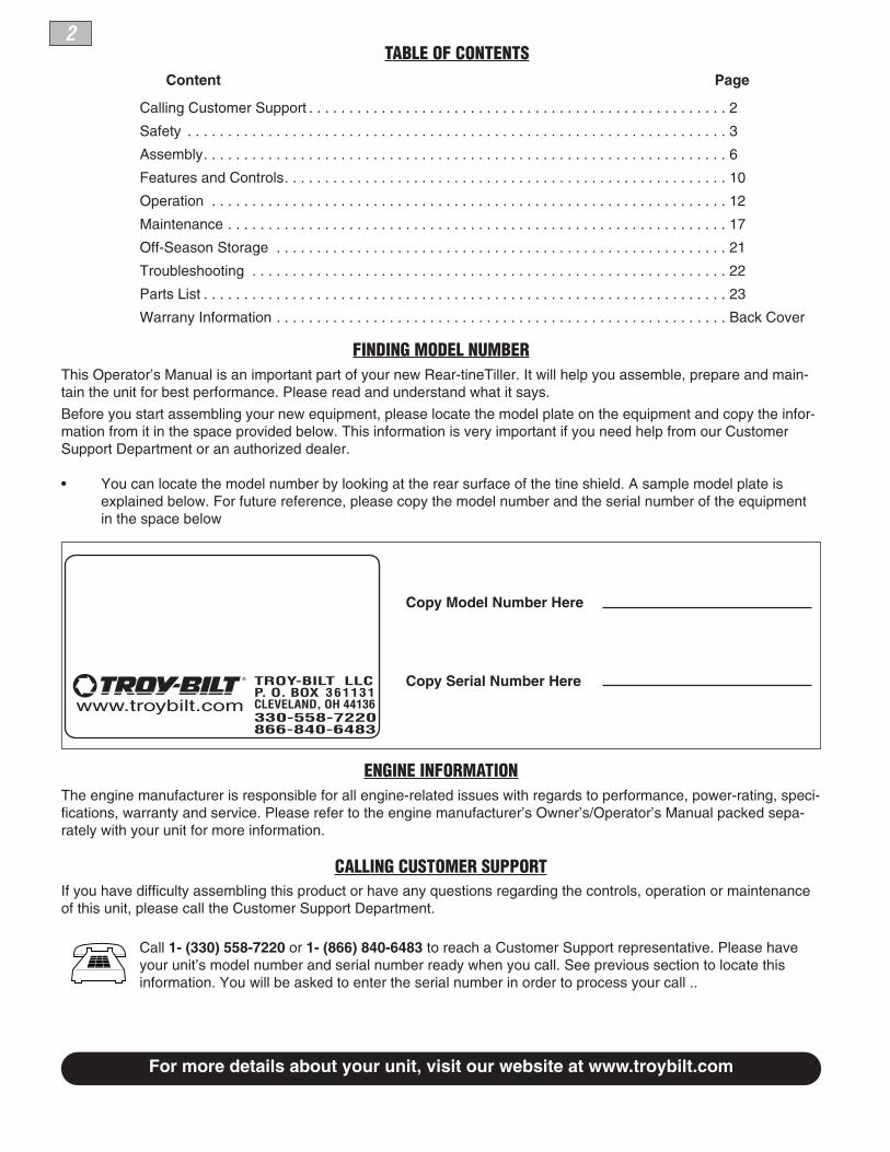
FINDING MODEL NUMBERThis Operator’s Manual is an important part of your new Rear-tineTiller. It will help you assemble, prepare and main-tain the unit for best performance. Please read and understand what it says.
Before you start assembling your new equipment, please locate the model plate on the equipment and copy the infor-mation from it in the space provided below. This information is very important if you need help from our CustomerSupport Department or an authorized dealer.
• You can locate the model number by looking at the rear surface of the tine shield. A sample model plate isexplained below. For future reference, please copy the model number and the serial number of the equipmentin the space below
ENGINE INFORMATIONThe engine manufacturer is responsible for all engine-related issues with regards to performance, power-rating, speci-fications, warranty and service. Please refer to the engine manufacturer’s Owner’s/Operator’s Manual packed sepa-rately with your unit for more information.
CALLING CUSTOMER SUPPORTIf you have difficulty assembling this product or have any questions regarding the controls, operation or maintenanceof this unit, please call the Customer Support Department.
Call 1- (330) 558-7220 or 1- (866) 840-6483 to reach a Customer Support representative. Please haveyour unit’s model number and serial number ready when you call. See previous section to locate thisinformation. You will be asked to enter the serial number in order to process your call ..
Copy Model Number Here
Copy Serial Number Here
www.troybilt.com
TROY-BILT LLCP. O. BOX 361131CLEVELAND, OH 44136
866-840-6483330-558-7220
2

Safety1Section
3
Training1. Carefully read this Owner’sManual, the separate EngineOwner’s Manual, and any
other literature you may receive. Be thor-oughly familiar with the controls and theproper use of the tiller and its engine.Know how to stop the unit and disengagethe controls quickly.
2. Never allow children to operate thetiller. Never allow adults to operate thetiller without proper instruction.
3. Keep the area of operation clear of allpersons, particularly children and pets.
4. Keep in mind that the operator or useris responsible for accidents or hazardsoccurring to other people, their property,and themselves.
Preparation1. Thoroughly inspect the area where thetiller is to be used and remove all foreignobjects.
2. Be sure all tiller controls are releasedand both wheels are in the Wheel Driveposition before starting the engine.
3. Do not operate the tiller without
wearing adequate outer garments. Avoidloose garments or jewelry that could getcaught in moving parts.
4. Do not operate the tiller when barefootor wearing sandals, sneakers, or lightfootwear. Wear protective footwear thatwill improve footing on slippery surfaces.
5. Do not till near underground electriccables, telephone lines, pipes or hoses. Ifin doubt, contact your telephone or utilitycompany.
6. Warning: Handle fuel with care; it ishighly flammable and its vapors are explo-sive. Take the following precautions:
a. Store fuel in containers specificallydesigned for this purpose.
b. The gas cap shall never be removedor fuel added while the engine is run-ning. Allow the engine to cool forseveral minutes before adding fuel.
c. Keep matches, cigarettes, cigars,pipes, open flames, and sparksaway from the fuel tank and fuelcontainer.
d. Fill fuel tank outdoors with extremecare. Never fill fuel tank indoors.Use a funnel or spout to preventspillage.
e. Replace all fuel tank and containercaps securely.
f. If fuel is spilled, do not attempt tostart the engine, but move themachine away from the area ofspillage and avoid creating anysource of ignition until fuel vaporshave dissipated.
7. Never make adjustments when engineis running (unless recommended by manufacturer).
Operation1. Do not put hands or feet near or underrotating parts.
2. Exercise extreme caution when on orcrossing gravel drives, walks, or roads.Stay alert for hidden hazards or traffic. Donot carry passengers.
3. After striking a foreign object, stop theengine, remove the wire from the sparkplug wire and prevent it from touching thespark plug. Thoroughly inspect themachine for any damage and repair thedamage before restarting and operatingthe machine.
BRONCO
Figure 1-1: Tiller features and controls (5.5HP Model shown). See separateEngine Owner’s Manual to identify engine controls.
Forward Clutch Bail
Depth Regulator
Tine Hood Flap
Standard-Rotating-Tines (SRT)
Wheel Drive Pin(on each wheel)
Reverse ClutchControl (Models
634F/634B)
The engine exhaust from this product containschemicals known to the State of California to causecancer, birth defects or other reproductive harm.
WARNING
This machine meets voluntary safety standardB71.8 – 1996, which is sponsored by the OutdoorPower Equipment Institute, Inc., and is publishedby the American National Standards Institute.
Safety Alert Symbol
This is a safety alert symbol. It is used in thismanual and on the unit to alert you to poten-tial hazards. When you see this symbol, readand obey the message that follows it. Failureto obey safety messages could result inpersonal injury or property damage.

4 Section 1: Safety
4. Exercise caution to avoid slipping orfalling.
5. If the unit should start to vibrate abnor-mally, stop the engine, disconnect thespark plug wire and prevent it fromtouching the spark plug, and check imme-diately for the cause. Vibration is gener-ally a warning of trouble.
6. Stop the engine, disconnect the sparkplug wire and prevent it from touching thespark plug, whenever you leave the oper-ating position, before unclogging the tines,or when making any repairs, adjustmentsor inspections.
7. Take all possible precautions whenleaving the machine unattended. Stop theengine. Disconnect the spark plug wireand move it away from the spark plug. Besure that both wheels are in the WheelDrive position.
8. Before cleaning, repairing, orinspecting, stop the engine and make cer-tain all moving parts have stopped. Dis-connect the spark plug wire and prevent itfrom touching the spark plug to preventaccidental starting.
9. The flap on the tine hood must be downwhen operating the tiller.
10. Never use the tiller unless properguards, plates, or other safety protectivedevices are in place.
11. Do not run the engine in an enclosedarea. Engine exhaust contains carbonmonoxide gas, a deadly poison that isodorless, colorless, and tasteless.
12. Keep children and pets away.
13. Never operate the tiller under enginepower if the wheels are in the Freewheelposition. In the Freewheel position, thewheels will not hold the tiller back and therevolving tines could propel the tillerrapidly, possibly causing loss of control.Always engage the wheels with the wheeldrive pins in the Wheel Drive positionbefore starting the engine or engaging thetines/wheels with the Forward Clutch Bail(all models) or the Reverse Clutch control(Models 634F/634B only).
14. Be aware that the tiller may unex-pectedly bounce upward or jump forwardif the tines should strike extremely hardpacked soil, frozen ground, or buriedobstacles like large stones, roots, orstumps. If in doubt about the tilling con-ditions, always use the following
operating precautions to assist you inmaintaining control of the tiller:
a. Walk behind and to one side of thetiller, using one hand on the han-dlebars. Relax your arm, but use asecure hand grip.
b. Use shallower depth regulator set-tings, working gradually deeperwith each pass.
c. Use slower engine speeds.d. Clear the tilling area of all large
stones, roots and other debris. e. Avoid using downward pressure on
the handlebars. If need be, useslight upward pressure to keep thetines from digging too deeply.
f. Before contacting hard packed soilat the end of a row, reduce enginespeed and lift the handlebars toraise the tines out of the soil.
g. In an emergency, stop the tines andwheels by releasing whicheverclutch control is engaged. Do notattempt to restrain the tiller.
15. Do not overload the tiller’s capacity byattempting to till too deeply at too fast arate.
16. Never operate the tiller at high trans-port speeds on hard or slippery surfaces.Look behind and use care when backingup.
17. Do not operate the tiller on a slopethat is too steep for safety. When onslopes, slow down and make sure youhave good footing. Never permit the tillerto freewheel down slopes.
18. Never allow bystanders near the unit.
19. Only use attachments and accessoriesthat are approved by the manufacturer ofthe tiller.
20. Use tiller attachments and accessorieswhen recommended.
21. Never operate the tiller without goodvisibility or light.
22. Never operate the tiller if you are tired;or under the influence of alcohol, drugs ormedication.
23. Operators shall not tamper with theengine-governor settings on the machine;the governor controls the maximum safeoperating speed to protect the engine andall moving parts from damage caused byoverspeed. Authorized service shall besought if a problem exists.
24. Do not touch engine parts which maybe hot from operation. Let parts cool downsufficiently.
25. Please remember: You can alwaysstop the tines and wheels by releasing theForward Clutch Bail or on Models 634Fand 634B the Reverse Clutch control,(whichever control is engaged), or bymoving the ignition switch and/or throttlecontrol lever on the engine to “OFF” or“STOP”.
26. To load or unload the tiller, see theinstructions in Section 4 of this Manual.
27. Use extreme caution when reversingor pulling the machine towards you.
28. Start the engine carefully according toinstructions and with feet well away fromthe tines.
29. Never pick up or carry a machinewhile the engine is running.
Maintenance and Storage1. Keep the tiller, attachments and acces-sories in safe working condition.
2. Check all nuts, bolts, and screws at frequent intervals for proper tightness tobe sure the equipment is in safe workingcondition.
3. Never store the tiller with fuel in the fueltank inside a building where ignitionsources are present such as hot water andspace heaters, furnaces, clothes dryers,stoves, electric motors, etc.). Allow theengine to cool before storing the unit inany enclosure.
4. To reduce the chances of a fire hazard,keep the engine free of grass, leaves, orexcessive grease.
5. Store gasoline in a cool, well-ventilatedarea, safely away from any spark- orflame-producing equipment. Store gaso-line in an approved container, safely awayfrom the reach of children.
6. Refer to the Maintenance sections ofthis Manual and the separate EngineOwner’s Manual for instructions if the unitis to be stored for an extended period.
7. Never perform maintenance while theengine is running or the spark plug wire isconnected, except when specificallyinstructed to do so.
8. If the fuel tank has to be drained, dothis outdoors.

Section 1: Safety 5
DecalsFor your safety and the safety ofothers, various safety and opera-tional decals are located on yourunit (see Figure 1-2).
Keep the decals clean and legible atall times. Contact your local ser-vice dealer or the factory forreplacements if any decals aredamaged or missing.
Refer to the Parts List pages in thisManual for decal locations, descrip-tions and part numbers.
BRONCO
Forward Clutch Bail Operating Instruction
Reverse Clutch ControlOperating Instruction(Models 634F/634B)
Warning Messages
Hot Surfaces Warning (on belt cover)
Starting StabilizationMessage (on engine)
Figure 1-2: Location of safety and operating decals (5.5HP Model shown).
TO AVOID SERIOUS INJURY:• READ THE OWNER’S MANUAL.• KNOW LOCATIONS AND FUNCTIONS OF ALL CONTROLS.• KEEP ALL SAFETY DEVICES AND SHIELDS IN PLACE AND WORKING.• NEVER ALLOW CHILDREN OR UNINSTRUCTED ADULTS TO OPERATE TILLER.• SHUT OFF ENGINE AND DISCONNECT SPARK PLUG WIRE BEFORE MANUALLY UNCLOG-
GING TINES OR MAKING REPAIRS.• KEEP BYSTANDERS AWAY FROM MACHINE.• KEEP AWAY FROM ROTATING PARTS.• USE EXTREME CAUTION WHEN REVERSING OR PULLING THE MACHINE TOWARDS YOU.
WARNING
Operating SymbolsVarious symbols (shown here, with worddescriptions) may be used on the tiller andengine. Your unit may not have all of the symbols.
FAST SLOW
CHOKEON
CHOKEOFF
STOP
STOP
REVERSER
ROTATINGTINES
BAILENGAGED
BAILDISENGAGED
TILLER DIRECTION LEVER DIRECTION

Assembly2Section
6
INTRODUCTIONCarefully follow these assembly steps tocorrectly prepare your tiller for use. It isrecommended that you read this Sectionin its entirety before beginning assembly.NOTE: Various tiller models are presentedin this Manual. Use only the informationappropriate for your tiller model.
INSPECT UNITInspect the unit and carton for damageimmediately after delivery. Contact thecarrier (trucking company) if you find orsuspect damage. Inform them of thedamage and request instructions for filinga claim. To protect your rights, put yourclaim in writing and mail a copy to the car-rier within 15 days after the unit has beendelivered. Contact the factory if you needassistance in this matter.
TOOLS/MATERIALS NEEDED FOR ASSEMBLY(1) 3/8” open-end wrench*(2) 7/16" open-end wrench*(2) 1/2" open-end wrench*(2) 9/16" open-end wrench*(1) Large adjustable wrench (Models
634F/634B only)(1) Scissors (to trim plastic ties)(1) Ruler (for belt tension check)(1) Block of wood (to support tiller
when removing wheels)(1) Tire pressure gauge (for models with
pneumatic tires)(1) Clean oil funnel(1) Motor oil. Refer to the Engine Owner’s
Manual for oil specifications andquantity required. * Adjustable wrenches may be used.
ASSEMBLY STEPS
STEP 1: UNPACKING INSTRUCTIONS
NOTE: While unpacking, do not severelybend any control cables.
1. The tiller weighs approximately 133 lbs.Do not attempt to remove it from the ship-ping platform until instructed to do so inthese Assembly steps.
2. Remove any packaging material fromthe carton. Remove any staples from thebottom of the carton and remove thecarton from the shipping platform.
3. Remove all unassembled parts and theseparate hardware bag from the carton.Check that you have the items listed in theLoose Parts List (contact your local dealeror the factory items are missing or dam-aged). NOTE: Use the screw length tem-plate (Fig. 2-1) to identify screws.
Loose Parts List
Qty. Description
1 Handlebar Support (see A, Fig. 2-2)1 Handlebar Assembly (see K, Fig. 2-2)
Hardware bag contents:1 Slotted hd. screw, #10-24 x 2"1 Hex hd. screw, 1/4-20 x 1-1/4"6 Hex hd. screw, 5/16-18 x 1-1/2"2 Hex hd. screw, 3/8-16 x 3/4"2 Flat washer, 3/8"6 Split lockwasher, 5/16"1 Hex locknut, 1/4"-206 Hex nut, 5/16"-181 Hex nut, #10-242 Hex locknut, 3/8"-161 Spring, cable (see W, Fig. 2-5)1 Bracket, forward clutch cable (see
P, Fig. 2-4)2 Lock Washer, 3/82 *Self-tapping screw, 1/4-20 x 1/2"1 *Bracket, reverse clutch cable
*Model 634F & 634B only
IMPORTANT: Motor oil must be added tothe engine crankcase before the engine isstarted. Follow the instructions in thisAssembly Section and in the separateEngine Owner’s Manual.
NOTE: LEFT and RIGHT sides of the tillerare as viewed from the operator’s positionbehind the handlebars.
STEP 2: ATTACH HANDLEBAR1. Loosely attach the legs of the handlebarsupport (A, Fig. 2-2) to the inner sides ofthe tiller frame using two 3/8"-16 x 3/4"hex hd. screws (B), 3/8" flat washers (C),3/8" lock washers (GG) and 3/8"-16 hexlocknuts (D).
2. There are three height adjustment holesin the two handlebar support brackets (Eand F, Fig. 2-2). Use a setting that willposition the handlebars at approximatelywaist level when the tines are 3"-4" into thesoil. Loosely attach the support bracketsto the handlebar support (A) using two5/16"-18 x 1-1/2" screws (G), 5/16" splitlockwashers (H) and 5/16"-18 hex nuts (I).NOTE: If a support bracket will not move,loosen attaching screw (J) and nut.
3. Attach the handlebar assembly (K) tothe handlebar support (A) using four5/16"-18 x 1-1/2" screws (G), 5/16" splitlockwashers (H) and 5/16"-18 hex nuts (I).Tighten the four screws securely.
4. Tighten all handlebar mounting hard-ware securely.
STEP 3: MOVE TILLER OFF SHIPPING PLATFORMTo roll the tiller off the shipping platform,put the wheels in FREEWHEEL, as follows:
1. Place a sturdy block under the trans-mission to raise one wheel about 1" off theground.
To prevent personal injury or propertydamage, do not start the engine untilall assembly steps are complete andyou have read and understand thesafety and operating instructions in thismanual.
WARNING
1
2
1
2Figure 2-1: To identify length of screws,place screw on template as shown and mea-sure distance between bottom of screw headand tip of screw.

Section 2: Assembly 7
2. Remove the hairpin cotter (L, Fig. 2-3)and wheel drive pin (M) from the wheelhub (O) and wheel shaft (N).
3. Slide the wheel fully inward on thewheel shaft (N, Fig. 2-3). Reinstall thewheel drive pin (M) through the wheelshaft only (not through the wheel hub).Secure the wheel drive pin with the hairpincotter (L), pushing the hairpin cotter in asfar as it will go. The wheel should nowspin freely (freewheel) on the wheel shaft.Repeat with the other wheel.
4. Use the handlebar to roll the tiller to aflat area.
IMPORTANT: Before starting the engine,the wheels must be placed in the WHEELDRIVE position (pins through wheel hubsand wheel shaft). This procedure isdescribed in Wheel Drive Pins in Section 3.
STEP 4: INSTALL FORWARD CLUTCH CABLE1. Attach the forward clutch cable bracket(P, Fig. 2-4) to the handlebar support (A)with a 1/4"-20 x 1-1/4" hex hd. screw (R)and 1/4"-20 hex locknut (S). Tightensecurely.
2. Carefully unwrap the forward clutchcable (cable without an attached knob)from its shipping position and slide thethin cable wire (T, Fig. 2-4) into the slot inthe cable bracket. Push the cable con-nector (U, Fig. 2-4) up through the hole inthe bracket until the groove in the con-nector snaps into place.
3. Insert the #10-24 x 2" slotted hd. screw(V, Fig. 2-5) down through the hookedend of the cable spring (W) until the screwthreads extend through the spring.
G
G
HA
I H
F
E
I
H IB
C
G
GG
K
J
D
Fig. 2-3: Wheel in FREEWHEEL position(wheel drive pin through wheel shaft only).
M
ON
L
Fig. 2-4: Installing forward clutch cable bracket and cable.
P
R
S
T
T
U
A
Fig. 2-2: Attach handlebar (5.5HP Model shown).

8 Section 2: Assembly
4. Thread the #10-24 hex nut (Z, Fig. 2-5)halfway onto the screw (V).
5. Thread the screw (V) into the cableadjuster (X).
6. Hook the cable spring (W, Fig. 2-6) intothe V-shaped bend in the Forward ClutchBail (Y).
7. Check for correct tension on the for-ward drive belt by taking two measure-ments of the cable spring, as follows:
a. With the Forward Clutch Bail (Y, Fig. 2-6) in an open (released) position, mea-sure the length of the cable spring (W)from the outermost coil to the outer-most coil.
b. Squeeze the Forward Clutch Bail againstthe handlebar (see Fig. 2-7) and re-measure the spring length. The belttension is correct if this second mea-surement is between 1/16" to 3/16"longer than the first measurement. Ifso, turn the hex nut (Z, Fig. 2-7) tightlyagainst the cable adjuster (X) while pre-venting the cable adjuster from turning.
c. If the spring length is incorrect, youmust adjust the cable tension asdescribed in Checking and AdjustingForward Drive Belt Tension in Section 5.Incorrect cable tension can result in beltslippage (cable tension too loose), orunintentional tine movement when theclutch bail is in Neutral (cable tensiontoo tight).
STEP 5: INSTALL REVERSE CLUTCHCABLE (MODELS 634F AND 634BONLY)1. Unwrap the reverse clutch cable (CC,Fig. 2-8 and Fig. 2-9) from its shippingposition and route it up to the handlebar.Be sure that the cable is routed beneaththe Forward Clutch Bail.
2. Using the two self-tapping screws (AA,Fig. 2-8) secure the reverse cablemounting bracket (BB)to the handlebars,as shown.
3. Insert the cable (CC, Fig. 2-8) throughthe slot in the cable bracket and positionthe flat side of the threaded assembly nextto the flat side of the hole. Slide the hexnut (DD) up the cable and tighten itsecurely.
4. Fasten the reverse clutch cable to theleft side handlebar with a cable tie (EE,Fig. 2-9).
5. Test the function of the reverse clutchby pulling out and releasing the cableknob. The knob should return to its neu-tral position (resting against bracket). If itdoesn’t, contact your local dealer or thefactory for technical assistance.
W
Z
X
V
Fig. 2-6: Attach forwardclutch cable spring toforward clutch bail.
Y
W
Fig. 2-5: Cablespring andadjuster.
Fig. 2-7: To check forward belt tension, take two measurements of the length of the coils inthe spring – first with the bail open, then with the bail held against the handlebar.
1
2
3
4
5
XZ
Hold bail against handlebar whiletaking second measurement of
spring
Fig. 2-8: Install reverse cable bracket andreverse clutch cable.
CC
AA
AABB
Flat Side
DD
Fig. 2-9: Route reverse clutch cable (CC) asshown. Attach with cable tie (EE).
BRONCO
CC
EE

Section 2: Assembly 9
STEP 6: CHECK LEVEL OF TRANSMISSION GEAR OILThe transmission was filled with gear oil atthe factory. However, you should checkthe gear oil level at this time to make cer-tain it is correct.
IMPORTANT: Do not operate the tiller ifthe gear oil level is low. Doing so willresult in severe damage to the transmis-sion components. 1. With the tiller on level ground, pull theDepth Regulator Lever (FF, Fig. 2-10) backand then all the way up until the lowestnotch in the lever is engaged.2. Remove the oil fill plug (GG, Fig. 2-11)from the transmission housing cover andlocate the main drive shaft situated insidethe housing.3. The gear oil level is correct if the gearoil is approximately halfway up the side ofthe main drive shaft.4. If the oil level is low, add gear oil byreferring to A. To Check the TransmissionGear Oil Level in Section 5.
STEP 7: ADD MOTOR OIL TO ENGINEThe tiller is shipped without oil in theengine.
IMPORTANT: Do not start the enginewithout first adding motor oil. Severeengine damage will result if the engine isrun without oil.1. Refer to the separate Engine Owner’sManual for engine oil specifications andcapacities. 2. With the tiller on level ground, move theDepth Regulator Lever (FF, Fig. 2-10) upor down until the engine is level.3. Add motor oil as described in theEngine Owner’s Manual.4. Move the Depth Regulator Lever all theway down until the highest notch isengaged. This places the tines in the“travel” position, which allows the tiller tobe moved without the tines touching theground.
STEP 8: CHECK HARDWARE FOR TIGHTNESSCheck all nuts and screws for tightness.
STEP 9: CHECK AIR PRESSURE INTIRES (units with pneumatic tires)On tires equipped with air valves, checkthe air pressure with a tire gauge. Deflateor inflate the tires equally to 15 to 20 PSI(pounds per square inch). Be sure thatboth tires are inflated equally or the unitwill pull to one side.
Fig. 2-10: Adjust Depth Regulator Lever.
FF
Fig. 2-11: Remove gear oil fill plug.
GG
IMPORTANT: This completes the assemblysteps. Before operating your tiller, make sureyou read the following sections in this Manual, aswell as the separate Engine Owner’s Manual:
• Section 1: Safety• Section 3: Features and Controls• Section 4: Operation

Features and Controls3Section
10
INTRODUCTIONThis Section describes the location andfunction of the controls on your tiller.Refer to the following Section, Operationfor detailed operating instructions.
Practice using these controls, with theengine shut off, until you understand theoperation of the controls and feel confi-dent with each of them.
ENGINE CONTROLSRefer to the engine manufacturer’s EngineOwner’s Manual (included in the tiller liter-ature package) to identify the controls onyour engine.
IMPORTANT: The control for stopping theengine is located on the engine.
WHEEL DRIVE PINS Each wheel is equipped with a wheel drivepin (A, Figures 3-2 and 3-3) that securesthe wheel to the wheel shaft (B). Thewheels can be positioned in either aWHEEL DRIVE or a FREEWHEEL mode.
Before starting the engine, put bothwheels in the WHEEL DRIVE position byinserting the wheel drive pins through thewheel hubs and the wheel shaft. Doing so“locks” the wheels to the wheel shaft,causing the wheels to turn when either the
Forward Clutch Bail (all models) or theReverse Clutch Control (Models 634F and634B) is engaged.
Use the FREEWHEEL mode only when theengine is not running. In FREEWHEEL, thewheel drive pins are placed only throughthe holes in the wheel shaft (not the wheelhubs), thus allowing the wheels to turnfreely when you manually move the tiller.
To place the wheels in WHEEL DRIVE orFREEWHEEL:1. Stop engine, disconnect spark plug wirefrom spark plug and allow engine to cool.
2. Raise one wheel about one inch off theground and place a sturdy support underthe transmission.
3. Remove hairpin cotter (C, Figures 3-2and 3-3) from wheel drive pin (A).
4. FOR WHEEL DRIVE MODE (Figure 3-2):Slide wheel outward and align holes inwheel hub (D, Figure 3-2) and wheel shaft(B). Insert wheel drive pin (A) through
wheel hub (D) and wheel shaft (B). Securewheel drive pin with hairpin cotter (C) bypushing hairpin cotter in as far as it willgo. Repeat with the other wheel and thenremove the support from beneath thetransmission.
5. FOR FREEWHEEL MODE (Figure 3-3):Slide the wheel inward and insert thewheel drive pin (A, Figure 3-3) onlythrough the hole in the wheel shaft (B).Secure wheel drive pin with hairpin cotter(C) by pushing hairpin cotter in as far as itwill go. Repeat for the other wheel andthen remove the support from beneath thetransmission.
Before operating your machine, care-fully read and understand all safety,controls and operating instructions inthis Manual, the separate EngineOwner’s Manual, and on the decals onthe machine.
Failure to follow these instructions canresult in serious personal injury.
WARNING
Never allow either of the wheels to bein the FREEWHEEL position when theengine is running. Always put bothwheels in the WHEEL DRIVE positionbefore starting the engine.
Failure to comply could cause loss oftiller control, property damage, or per-sonal injury.
WARNING
Figure 3-1: Tiller features and controls (5.5HP Model shown). See separate Engine Owner’sManual to identify engine controls.
BRONCO
Wheel Drive Pin (on each wheel)
Forward Clutch Bail
Reverse ClutchControl (Models
634F/634B)
Depth Regulator
Handlebar HeightAdjustment
Do not place tiller on its side whenchanging wheel drive positions. Doingso could result in gasoline leaking fromthe fuel tank.
Failure to follow this instruction couldresult in personal injury or propertydamage.
WARNING
Figure 3-2: WHEEL DRIVE position.
A
B
D
C

Section 3: Features and Controls 11
FORWARD CLUTCH BAILThe Forward Clutch Bail (E, Figure 3-4)controls the engagement of forward driveto the wheels and tines.
To operate the Forward Clutch Bail:
1. Put wheels in WHEEL DRIVE position(see “WARNING” statement above).
2. Lift and hold the clutch bail (E, Figure3-4) against the handlebar to start thewheels and tines rotating in a forwarddirection.
3. Release the clutch bail to disengage(stop) the wheels and tines (the enginewill continue to run).
REVERSE CLUTCH CONTROL (Models 634F/634B only)The Reverse Clutch Control (F, Figure 3-4)controls the engagement of reverse driveto the wheels and tines. The reversingfeature is used for maneuvering the tilleronly – never engage the tines in theground while operating in reverse.
To operate the Reverse Clutch Control:
1. Put wheels in WHEEL DRIVE position(see “WARNING” statement at the left).
2. Stop all tiller motion by releasing theForward Clutch Bail.
3. Lift the handlebar until the tines clearthe ground, look behind you to avoid anyobstacles, and then pull the control knob(F, Figure 3-4) out. The wheels and tineswill rotate in a reverse direction.
4. Release the control knob to disengage(stop) the wheels and tines (the enginewill continue to run).
DEPTH REGULATOR LEVERThis lever (G, Figure 3-5) controls thetilling depth of the tines. Pull the leverback and slide it up or down to engage thenotched height settings.
The “travel position” (highest notch) raisesthe tines approximately 1-1/2" off theground, allowing the tiller to be movedwithout the tines contacting the ground.This setting should also be used whenstarting the engine.
Moving the lever upward will increase thetilling depth. The lowest notch allows atilling depth of approximately 6",depending on soil conditions. For best
results, always begin tilling at a veryshallow depth setting and graduallyincrease the tilling depth.
HANDLEBAR HEIGHT ADJUSTMENTThe handlebar height is adjustable to threedifferent settings (Figure 3-6). In general,adjust the handlebars so they are at waistlevel when the tines are 3"-4" in the soil.
To adjust the handlebars:
1. Stop engine, disconnect spark plugwire from spark plug and allow engine tocool.
2. Remove hardware, reposition handle-bars, and reinstall hardware securely.
Figure 3-3: FREEWHEEL position.
A
B
D
C
Before starting engine, be sure that bothwheels are in WHEEL DRIVE position.See Wheel Drive Pins for instructions.
Engaging the Forward Clutch Bail orReverse Clutch Control (if equipped)when the wheels are not in WHEELDRIVE could allow the tines to rapidlypropel the tiller forward or backward.
Failure to comply could cause loss oftiller control, property damage, or per-sonal injury.
WARNING
Figure 3-4: All models have a ForwardClutch Bail (E). Only Models 634F/634Bhave a Reverse Clutch Control (F).
F
E
• Use extreme caution when reversingor pulling the machine towards you.Look behind to avoid obstacles.
• Never attempt to till in reverse.
Failure to follow this warning couldresult in personal injury or propertydamage.
WARNING
• Do not attempt to till too deeply tooquickly. Gradually work down todeeper tilling depths.
• Place the Depth Regulator Lever inthe “travel” position before startingthe engine. This position preventsthe tines from touching the grounduntil you are ready to begin tilling.
Failure to follow this warning couldresult in personal injury or propertydamage.
WARNING
Figure 3-5: Depth Regulator Lever (G).
Travel Position
ShallowSettings
Deep Settings
G
Figure 3-6: Handlebar height adjustment.
High
Low
Medium

Operation4Section
12
INTRODUCTIONRead this Operation Section and the sepa-rate Engine Owner’s Manual before youstart the engine. Then, take the time tofamiliarize yourself with the basic opera-tion of the tiller before using it in thegarden. Find an open, level area and prac-tice using the tiller controls without thetines engaging the soil (put tines in“travel” setting). Only after you’vebecome completely familiar with the tillershould you begin using it in the garden.
BREAK-IN OPERATIONPerform the following maintenance afterthe first two (2) hours of new operation(see Maintenance Section in this manualand in the Engine Owner’s Manual).1. Change engine oil.2. Check for loose or missing hardwareon unit. Tighten or replace as needed.3. Check tension on forward drive belt.4. Check transmission gear oil level.
STARTING AND STOPPING THE ENGINEPre-Start Checklist
With the spark plug wire disconnectedfrom the spark plug, perform the followingchecks and services before each use:1. Read the Safety and Controls Sectionsin this manual. Read the separate EngineOwner’s Manual provided with the unit.2. Put the wheels in the WHEEL DRIVEposition (wheel pins must be throughholes in wheel hubs and wheel shaft).3. Check unit for loose or missing hard-ware. Service as required.4. Check engine oil level. See EngineOwner’s Manual.
5. Check that all safety guards and coversare in place.6. Check air cleaner and engine coolingsystem. See Engine Owner’s Manual.
7. Fill the fuel tank with gasolineaccording to the directions in the separateEngine Owner’s Manual. Follow allinstructions and safety rules carefully.8. Attach spark plug wire to spark plug.
Starting the Engine
The following steps describe how to startand stop the engine. Do not attempt toengage the tines or wheels until youhave read all of the operating instruc-tions in this Section. Also, review thesafety rules in Section 1: Safety, and thetiller and engine controls information inSection 3: Features and Controls.
1. Complete the Pre-Start Checklist onthis page. 2. Put the wheels in the WHEEL DRIVEposition (see Wheel Drive Pins in Section3 of this manual).
3. Move the Depth Regulator Lever all theway down to the “travel” position, so thatthe tines clear the ground.4. Release all controls on the tiller.5. On engine’s with a fuel shut-off valve,turn valve to open position, as instructedin the separate Engine Owner’s Manual.6. Put ignition switch and/or throttle con-trol lever located on engine in the “ON”,“RUN”, “FAST” or “START” position, asinstructed in the Engine Owner’s Manual.7. Choke or prime engine, as instructed inEngine Owner’s Manual.8. Put one hand on fuel tank to stabilizeunit when pulling starter rope handle.Then use recoil starter to start engine, asinstructed in the Engine Owner’s Manual.When engine starts, gradually move chokelever (if so equipped) to “NO CHOKE”,“CHOKE OFF” or “RUN” position.9. Use the “FAST” throttle speed settingwhen tilling.
Fig. 4-1
BRONCO
Wheel Drive Pin (on each wheel)
Forward Clutch Bail
Reverse Clutch Control (Models 634F/634B)
DepthRegulator
Recoil Starter
Before operating your machine, care-fully read and understand all safety(Section 1), controls (Section 3) andoperating instructions (Section 4) inthis Manual, in the separate EngineOwner’s Manual, and on the decals onthe machine.
Failure to follow these instructions canresult in serious personal injury.
WARNING
GASOLINE IS HIGHLY FLAMMABLE ANDITS VAPORS ARE EXPLOSIVE.
Follow gasoline safety rules in thisManual (see Section 1) and in the sepa-rate Engine Owner’s Manual.
Failure to follow gasoline safety instruc-tions can result in serious personalinjury and property damage.
DANGER
To help prevent serious personal injuryor damage to equipment:
• Before starting engine, put bothwheels in the WHEEL DRIVE position.Never have wheels in FREEWHEELposition when engine is running.When the wheels are in FREEWHEEL,they do not hold back the tiller and thetines could propel the tiller rapidly forward or backward.
• Before starting engine, put ForwardClutch Bail (all models) and ReverseClutch Control (Models 634F/634Bonly) in neutral (disengaged) positionsby releasing levers.
• Never run engine indoors or inenclosed, poorly ventilated areas.Engine exhaust contains carbonmonoxide, an odorless and deadly gas.
• Avoid engine muffler and nearbyareas. Temperatures in these areasmay exceed 150oF.
CAUTION

Section 4: Operation 13
Stopping the Engine and Tiller1. To stop the wheels and tines, releasethe Forward Clutch Bail (all models) or theReverse Clutch Control (Models 634F and634B) – whichever control is in use.2. To stop the engine, put the ignitionswitch and/or the throttle control lever inthe “OFF” or “STOP” position.
OPERATING THE TILLERThe following operating instructions pro-vide guidelines to using your tiller effec-tively and safely. Be sure to read TillingTips & Techniques in this Section beforeactually putting the tines into the soil.
NOTE: This is a traditional “Standard-Rotating-Tine” (SRT) tiller with forwardrotating tines. It operates completely dif-ferently from “Counter-Rotating-Tine”(CRT) tillers or from front-tine tillers.
1. Follow the Pre-Start Checklist at thebeginning of this Section. Be sure that thewheels are in the WHEEL DRIVE position.2. Move the Depth Regulator Lever all theway down, so that the tines clear theground. Use this position when practicingwith the tiller and when traveling betweentilling sites. Before actually tilling, movethe lever to the desired depth setting (seeTilling Tips & Techniques).3. Start engine and allow it to warm up.Then put throttle in “FAST” setting.
4. For forward motion of the wheels andtines:(a) Pull Forward Clutch Bail (Fig. 4-1) up
against handlebar. Release bail to stopforward motion of wheels and tines.
(b) When tilling, relax and let the wheelspull the unit while the tines dig. Walkbehind and a little to one side of theunit. Use one hand, yet keep a light—but secure—grip on the handlebar(while keeping your arm loose). SeeFig. 4-2. Let the unit move at its ownpace and do not push down on thehandlebars to try and force the tines todig deeper — this takes weight off thewheels, reduces traction, and causesthe tines to try and propel the tiller.
5. For reverse motion of the wheels andtines (Models 634F/634B only):(a) Look behind and exercise caution when
operating in reverse. Do not till whilein reverse.
(b) Stop all forward motion. Lift handlebarwith one hand until tines are off theground and then pull Reverse ClutchControl knob out (see Fig. 4-3). Tostop reversing, let go of Reverse ClutchControl knob.
6. To move the Model 630B in reverse forshort distances:(a) Release Forward Clutch Bail. Then lift
handlebar until tines are off the ground.
(b) Swing the handlebar to the left so theright wheel takes a “step” backward.Next swing the handlebar to the rightso the left wheel “steps” backward.Repeat as needed.
(c) If longer distances need to be coveredin reverse, shut off the engine, thenplace the two wheels in FREEWHEEL.
7. To Turn the Tiller Around:(a) Practice turning the tiller in a level,
open area. Be very careful to keepyour feet and legs away from the tines.
(b) To begin a turn, lift the handlebars untilthe tines are out of the ground and theengine and tines are balanced over thewheels (Fig. 4-4).
(c) With tiller balanced, push sideways onhandlebar to steer in direction of turn(Fig. 4-5). After turning, slowly lowertines into soil to resume tilling.
Stopping the Tiller and Engine1. To stop the wheels and tines, releasethe Forward Clutch Bail (all models) or theReverse Clutch Control (Models 634F and634B) – whichever control is in use.2. To stop the engine, put the ignitionswitch and/or the throttle control lever inthe “OFF” or “STOP” position.
Keep away from rotating tines. Rotatingtines will cause injury.
WARNING
Fig. 4-2: Use one hand to guide tiller whenmoving forward.
Do not push down on the handlebars totry to make the tiller till more deeply.This prevents the wheels from holdingthe tiller back and can allow the tinesto rapidly propel the tiller forward,which could result in loss of control,property damage, or personal injury.
WARNING
Fig. 4-3: Raise tines off ground and lookbehind when moving in reverse.
Fig. 4-4: To begin turn, lift handlebars untiltines are out of ground and unit is balanced.
Fig. 4-5: With tines out of ground, pushhandlebars sideways to turn tiller.

14 Section 4: Operation
Preparing Seedbeds
Fig. 4-6 Fig. 4-7
• If the garden size will not permitlengthwise and then crosswisetilling, then overlap the first passesby one-half a tiller width, followedby successive passes at one-quarter width (see Fig. 4-8).
With planning, you canallow enough roombetween rows to cultivate(see Fig. 4-9). Leave roomfor the hood width, plusenough extra room forfuture plant growth. Fig. 4-9
1
2
3
Fig. 4-8
Cultivating
• When preparing a seedbed, go over the same path twice in the first row, thenoverlap one-half the tiller width on the rest of the passes (see Fig. 4-6). When finished in one direction, make a second pass at a right angle, asshown in Fig. 4-7. Overlap each pass for best results (in very hard ground, itmay take three or four passes to thoroughly pulverize the soil.)
Tilling wet soil often results in large, hardclumps of soil that can interfere withplanting. If time permits, wait a day or twoafter heavy rains to allow the soil to drybefore tilling. Test soil by squeezing it intoa ball. If it compresses too easily, it is toowet to till.
Avoid Tilling Soggy, Wet Soil
Whenever possible, walk on the untilledside of the unit to avoid making footprintsin your freshly tilled or cultivated soil.Footprints cause soil compaction that canhamper root penetration and contribute tosoil erosion. They can also “plant”unwanted weed seeds back into thefreshly tilled ground.
While tilling, relax and let the wheels pullthe tiller along while the tines do the dig-ging. Walk on the side that is not yet fin-ished (to avoid making footprints in thefreshly tilled soil) and lightly, but securelygrip the handlebar with just one hand.
Let the Tiller Do the Work Avoid Making Footprints
• Avoid pushing down on the handlebars in an attempt to force the tiller to dig deeper. Doingso takes the weight off the powered wheels, causing them to lose traction. Without thewheels helping to hold the tiller back, the tines will attempt to propel the tiller – oftencausing the tiller to skip rapidly across the ground. (Sometimes, slight downward pressureon the handlebars will help get through a particularly tough section of sod or unbrokenground, but in most cases this won’t be necessary.)
• Avoid trying to dig too deeply too quickly, especially when busting sod or when tilling soilthat hasn’t been tilled for some time. Use shallow depth regulator settings (only an inch ortwo deep) for the first passes through the soil. With each succeeding pass, dig another inchor two deeper. (Watering the area a few days prior to tilling will make tilling easier, as willletting the newly worked soil set for a day or two before making a final, deep tilling pass.)
• When cultivating (breaking up surface soil around plants to destroy weeds, see Fig. 4-9), adjust the tines to dig only 1" to 2" deep.Using shallow tilling depths helps prevent injury to plants whose roots often grow close to the surface. If needed, lift up on the handle-bars slightly to prevent the tines from digging too deeply. (Cultivating on a regular basis not only eliminates weeds, it also loosens andaerates the soil for better moisture absorption and faster plant growth.)
With experience, you will find the “just right” tilling depth and tilling speed combination that is bestfor your garden.
Set the engine throttle lever at a speed to give the engine adequate power and yet allow it to operate at the slowest possible speed...atleast until you have achieved the maximum tilling depth you desire. Faster engine speeds may be desirable when making final passesthrough the seedbed or when cultivating. Selection of the correct engine speed, in relation to the tilling depth, will ensure a sufficientpower level to do the job without causing the engine to labor.
TILLING TIPS & TECHNIQUES
Tilling Depths
Choosing Correct Wheel and Tine Speeds
Before tilling, contact your tele-phone or utilities company andinquire if underground equipmentor lines are used on your property.Do not till near buried electriccables, telephone lines, pipes orhoses.
WARNING

Section 4: Operation 15
TILLING TIPS & TECHNIQUES (cont.)
Power composting simply means tilling under and burying in the soil all manner oforganic matter such as crop residues, leaves, grass clippings and cover crops. Thismaterial will decompose during the non-growing season and add important natural nutri-ents to the soil.
The first place to begin is with crop residues such as leftover vines, stalks, stems androots. Power compost these crop residues as soon as they finish bearing. The soonerthis is done, the better, as tender green matter is easier to till under. Use the deepestdepth regulator setting possible without causing the engine to labor or the tiller to jumpahead.
Standing cornstalks of reasonable height can be power composted. Pushing over (butnot uprooting) cornstalks will often make it easier to chop up the stalks. Keep the tinesclear of excessive tangling by “fishtailing” or frequently using reverse. Make severalpasses, then return a few days later to finish off any remaining stubble.
After tilling under crop residues, add more organic matter such as leaves, grass clippings and even kitchen scraps. When tilled into thesoil, this organic matter will decompose and add even more important nutrients to the soil.
After power composting, you may want to plant a “green manure” cover crop to protect the soil during the off-season. You simplygrow a crop of clover, alfalfa, buckwheat, peas, beans, rye grass, grain, or kale and then till it into the soil prior to the planting season.
When power composting, do not keepthe Depth Regulator Lever at a deepsetting if the tiller jumps or bucks.
If jumping or bucking occurs, move theDepth Regulator Lever down to ashallow setting and then slowlyincrease the tilling depth on laterpasses.
Failure to follow this warning couldresult in personal injury.
WARNING
Tilling On Slopes
Power Composting
Tilling Up and Down Slopes (Vertical Tilling)
• To keep soil erosion to a minimum, be sure to add enough organic matter to thesoil so that it has good moisture-holding texture and try to avoid leaving footprintsor wheel marks.
• When tilling vertically, try to make the first pass uphill as the tiller digs moredeeply going uphill than it does downhill. In soft soil or weeds, you may have tolift the handlebars slightly while going uphill. When going downhill, overlap thefirst pass by about one-half the width of the tiller.
Tilling Across Slopes Without Using Terraces (Horizontal Tilling)
• If vertical or terracing gardening aren’tpractical for you, then you can till laterallyacross a slope. We don’t recommend thismethod as it can create unsure footing andinvites soil erosion.
• As in terrace gardening, start at the top ofthe slope and overlap the first pass by halfthe width of the tiller. For added stability ofthe tiller, always keep the uphill wheel in thesoft, newly tilled soil.
Read the following recommendations before tilling on slopes:
If you must garden on a moderate slope, please follow two very important guidelines:
1. Till only on moderate slopes, never on steep ground where footing is difficult(review safety rules in Section 1: Safety of this manual).
2. We recommend tilling up and down slopes rather than terracing. Tilling verticallyon a slope allows maximum planting area and also leaves room for cultivating.
IMPORTANT: When tilling on slopes, be sure the correct oil level is maintained inthe engine (check every one-half hour of operation). The incline of the slope willcause the oil to slant away from its normal level and this can starve engine parts ofrequired lubrication. Keep the motor oil level at the full point at all times!
Do not operate tiller on a slope toosteep for safe operation. Till slowlyand be sure you have good footing.Never permit tiller to freewheel downslopes. Failure to follow this warningcould result in personal injury.
WARNING
Terrace Gardening
• When a slope is too steep or too short for vertical tilling, it may be necessary to till across the slope and create terraced rows. Ter-races are rows that are cut into the side of a slope, creating a narrow, but flat area on which to plant.
• On a long slope, you can make several terraces, one below the other.
• Terraces should be only 2-to-3 feet wide. Digging too far into the side of the slope will expose poor subsoil that is unproductive forplants.

16 Section 4: Operation
The tines have a self-clearing action which eliminates most tangling of debris inthe tines. However, occasionally dry grass, stringy stalks or tough vines maybecome tangled. Follow these procedures to help avoid tangling and to cleanthe tines, if necessary.
• To reduce tangling, set the depth regulator deep enough to get maximum“chopping” action as the tines chop the material against the ground. Also, tryto till under crop residues or cover crops while they are green, moist andtender.
• While power composting, try swaying the handlebars from side to side (about6" to 12"). This “fishtailing” action often clears the tines of debris.
• If tangling occurs, lift the tines out of the soil and run the tiller in reverse (ifunit is equipped with powered reverse) for a few feet. This reversing actionshould unwind a good deal of debris.
TILLING TIPS & TECHNIQUES (cont.)
Clearing the Tines
Before clearing the tines by hand, stop theengine, allow all moving parts to stop anddisconnect the spark plug wire. Remove theignition key on electric start models.
Failure to follow this warning could result inpersonal injury.
WARNING
• It may be necessary to remove the debris byhand (a pocket knife will help you to cut awaythe material). Be sure to stop the engine anddisconnect the spark plug wire before clearingthe tines by hand.
Terrace Gardening (continued)
• To create a terrace, start at the top of the slope and work down. Go back and forthacross the first row as shown in Fig. 4-10.
• Each succeeding lower terrace is started by walking below the terrace you’repreparing. For added stability of the tiller, always keep the uphill wheel in the soft,newly tilled soil. Do not till the last 12" or more of the downhill outside edge of eachterrace. This untilled strip helps prevents the terraces from breaking apart andwashing downhill. It also provides a walking path between rows. Fig. 4-10
12
3
12" UNTILLED
1 REPEAT
DOWNHILL
UPHILL
LOADING AND UNLOADING THE TILLER
• Before loading or unloading, stop theengine, wait for all parts to stop moving,disconnect the spark plug wire and letthe engine and muffler cool.
• The tiller is too heavy and bulky to liftsafely by one person. Two or morepeople should share the load.
• Use sturdy ramps and manually (engineshut off) roll the tiller into and out of thevehicle. Two or more people are neededto do this.
• The ramps must be strong enough tosupport the combined weight of the tillerand any handlers. The ramps should pro-vide good traction to prevent slipping;they should have side rails to guide thetiller along the ramps; and they shouldhave a locking device to secure them tothe vehicle.
• The handlers should wear sturdy footwearthat will help to prevent slipping.
• Position the loading vehicle so that theramp angle is as flat as possible (the lessincline to the ramp, the better). Turn thevehicle’s engine off and apply its parkingbrake.
• When going up ramps, stand in thenormal operating position and push the
tiller ahead of you. Have a person ateach side to turn the wheels.
• When going down ramps, walk backwardwith the tiller following you. Keep alertfor any obstacles behind you. Position aperson at each wheel to control thespeed of the tiller. Never go down rampstiller-first, as the tiller could tip forward.
• Place wooden blocks on the downhillside of the wheels if you need to stop thetiller from rolling down the ramp. Also,use the blocks to temporarily keep thetiller in place on the ramps (if neces-sary), and to chock the wheels in placeafter the tiller is in the vehicle.
• After loading the tiller, prevent it fromrolling by engaging the wheels in theWHEEL DRIVE position. Chock thewheels with blocks and securely tie thetiller down.
Loading and unloading the tiller into avehicle is potentially hazardous and wedon’t recommend doing so unless abso-lutely necessary, as this could result inpersonal injury or property damage.
However, if you must load or unload thetiller, follow the guidelines given next.
WARNING

Maintenance5Section
17
Before inspecting, cleaning or servicing the machine, shut off engine,wait for all moving parts to come to acomplete stop, disconnect spark plugwire and move wire away from sparkplug. Remove ignition key on electricstart models.
Failure to follow these instructions canresult in serious personal injury or prop-erty damage.
WARNING
MAINTENANCE SCHEDULEPROCEDURE NOTES
Check motor oil level 2, 3
Clean engine 2, 7
Check drive belt tension 1, 4
Check nuts and bolts 1, 4
Change motor oil 4, 6, 9
Lubricate tiller 4
Service engine air cleaner system 7
Check gear oil level in transmission 1, 5
Check tines for wear 5
Check air pressure in tires (if unithas pneumatic tires) 5
Service spark plug 7
NOTES1 - Check after first 2 hours of break-in operation.2 - Before each use.3 - Every 5 operating hours.4 - Every 10 operating hours.5 - Every 30 operating hours.6 - Change more frequently in dusty or dirty
conditions.7 - See Engine Owner’s Manual for service
recommendations.8 - Whichever time interval occurs first.9 - Change after first 2 hours of break-in
operation.
TILLER LUBRICATIONAfter every 10 operating hours, oil orgrease the lubrication points shown inFigure 5-1 and described below.
Use clean lubricating oil (#30 weightmotor oil is suitable) and clean generalpurpose grease (grease containing a metallubricant is preferred, if available).
• Remove the wheels, clean the wheelshaft (A, Fig. 5-1) and apply a thincoating of grease to the wheel shaft.
• Grease the back, front and sides of thedepth regulator lever (B, Fig. 5-1).
• Remove the tines and clean the tine shaft(C, Fig. 5-1). Use a file or sandpaper togently remove any rust, burrs or roughspots (especially around holes in shaft).Apply grease to ends of shaft beforeinstalling tines.
• Oil the threads on the handlebar heightadjustment screws and the handlebarattaching screws (D, Fig. 5-1).
Figure 5-1A
B
C
D
If a cover is leaking, check for loosescrews. If the screws are tight, a newgasket or oil seal may be required.
If the leak is from around a shaft and oilseal, the oil seal probably needs to bereplaced. See your authorized dealer orcontact the factory for service or advice.
IMPORTANT: Never operate the tiller if thetransmission is low on oil. Check the oillevel after every 30 hours of operation andwhenever there is any oil leakage.
CHECK HARDWARECheck for loose or missing hardware afterevery 10 operating hours and tighten orreplace (as needed) before reusing tiller
Be sure to check the screws underneaththe tiller hood that secure the transmissioncover and the Depth Regulator Lever to thetransmission.
CHECK TIRE PRESSURE(Models with pneumatic tires)Check the air pressure in both tires. Theair pressure should be between 15-20 PSI(pounds per square inch).
Keep both tires equally inflated to helpprevent machine from pulling to one side.
TRANSMISSION GEAR OIL SERVICECheck the transmission gear oil level afterevery 30 hours of operation or wheneveryou notice any oil leak. Operating the tillerwhen the transmission is low on oil canresult in severe damage.
A. To Check the Transmission Gear Oil Level:
1. Check the gear oil level when the trans-mission is cool. Gear oil will expand inwarm operating temperatures and thisexpansion will provide an incorrect oillevel reading.
2. With the tiller on level ground, pull theDepth Regulator Lever all the way up.
3. Remove the oil fill plug (A, Fig. 5-2)from the transmission housing and lookinside the oil fill hole to locate the maindrive shaft situated below the hole.
CHECK FOR OIL LEAKSBefore each use, check the tiller for signsof an oil leak – usually a dirty, oily accu-mulation either on the unit or on the floor.
A little seepage around a cover or an oilseal is usually not a cause for alarm. How-ever, if the oil drips overnight, then imme-diate attention is needed. Ignoring an oilleak can result in severe transmissiondamage!

18 Section 5: Maintenance
Before inspecting, cleaning or servicing the machine, shut off engine, wait for all moving parts tocome to a complete stop, disconnect spark plug wire and move wire away from spark plug.Failure to follow these instructions can result in serious personal injury or property damage.
WARNING
4. The gear oil level is correct if the gearoil is approximately halfway up the side ofthe main drive shaft.
5. If the gear oil level is low, add gear oilas described next. If the gear oil level isokay, securely replace the oil fill plug.
IMPORTANT: Do not operate the tiller ifthe gear oil level is low. Doing so willresult in severe damage to the transmis-sion components.
6. If adding only a few ounces of gear oil,use API rated GL-4 or GL-5 gear oil havinga viscosity of SAE 140, SAE 85W-140 orSAE 80W-90. If refilling an empty trans-mission, use only GL-4 gear oil having aviscosity of SAE 85W-140 or SAE 140.
IMPORTANT: Do not use automatic trans-mission fluid or motor oil in the transmis-sion.
7. While checking frequently to avoidoverfilling, slowly add gear oil into the oilfill hole until it reaches the halfway pointon the drive shaft.
8. Securely replace the oil fill plug.
B. To Drain the Transmission Gear Oil:The transmission gear oil does not need tobe changed unless it has been contami-nated with dirt, sand or metal particles. 1. Drain gasoline from the fuel tank or runthe engine until the fuel tank is empty. See“DANGER” statement below.
2. Drain the oil from the engine.3. Remove four screws (B, Figure 5-2) andremove transmission cover and gasket.4. Remove the left-side wheel.5. Tilt the left-side wheel shaft into a drainpan and allow the gear oil to drain throughthe top of the transmission.6. Reinstall the wheel. 7. Install a new gasket (do not reuse oldgasket) and reinstall the transmissioncover. 8. Refill the transmission using GL-4 gearoil (SAE 85W-140 or SAE 140).9. Refill the engine with motor oil andreplenish the fuel tank with gasoline.
BOLO TINESThe bolo tines will wear with use andshould be inspected at the beginning ofeach tilling season and after every 30operating hours. The tines can bereplaced either individually or as a com-plete set. See the Parts List pages for tineidentification and part numbers.
A. Tine Inspection:With use, the tines will become shorter,narrower and pointed. Badly worn tineswill result in a loss of tilling depth, andreduced effectiveness when chopping upand turning under organic matter.
B. Removing/Installing a Single Tine:1. With the engine shut off and the sparkplug wire disconnected, remove the twoscrews (A, Figure 5-3), lockwahers (E) andnuts (B) that attach a single tine to a tineholder. If needed, use penetrating oil onthe nuts.
2. When installing a single tine, be sure toposition it so that its cutting edge (sharp)will enter the soil first as the tiller movesforward.
C. Removing/Installing a Tine Assembly:1. A tine assembly consists of eight tinesmounted on a tine holder.
2. If removing both tine assemblies, markthem “left” and “right” before removal.Remove the screw (C, Figure 5-3), lockwasher (E) and locknut (D) that secure thetine assembly to the tine shaft. If neces-sary, use a rubber mallet to tap the tineassembly outward off the shaft.
3. Before reinstalling the tine assembly,inspect the tine shaft for rust, rough spotsor burrs. Lightly file or sand, as needed.Apply a thin coat of grease to the shaft.
4. Install each tine assembly so that thecutting (sharp) edge of the tines will enterthe soil first when the tiller movesforward. Secure the tine assembly to thetine shaft using the screw and locknut previously removed.
Gasoline is highly flammable and itsvapors are explosive. Follow thesesafety practices to prevent personalinjury or property damage from fire orexplosion.
• Allow the engine and muffler to coolfor at least two minutes beforedraining the tiller’s gasoline tank.
• Do not allow open flames, sparks,matches or smoking in the area.
• Wipe away spills and push tiller awayfrom spilled fuel.
• Use only an approved fuel containerand store it safely out of the reach ofchildren.
• Do not store gasoline in an area whereits vapors could reach an open flameor spark, or where ignition sources arepresent (such as hot water and spaceheaters, furnaces, clothes dryers,stoves, electric motors, etc.)
DANGER
Figure 5-2: Remove oil fill plug (A) to checkgear oil level and to add gear oil. Removefour cover screws (B) to drain gear oil.
B
BA

Section 5: Maintenance 19
Before inspecting, cleaning or servicing the machine, shut off engine, wait for all moving parts tocome to a complete stop, disconnect spark plug wire and move wire away from spark plug.Failure to follow these instructions can result in serious personal injury or property damage.
WARNING
CHECKING AND ADJUSTINGFORWARD DRIVE BELT TENSIONIt is important to maintain correct tensionon the forward drive belt. A loose belt willcause the tines and wheels to slow down –or stop completely – even though theengine is running at full speed. A too tightbelt can result in unintentional tine move-ment when the clutch bail is in the Neutral(released) position.
• Check belt tension after the first twohours of break-in operation and afterevery 10 operating hours.
• At the end of each tilling season, checkthe belt for cracks, cuts or frayed edgesand replace it as soon as possible.
To Check Forward Belt Tension:1. Stop engine, wait for all parts to stopmoving and disconnect spark plug wire.
2. With the Forward Clutch Bail in anopen (released) position, measure andnote the overall length of the cable spring(A, Figure 5-4) by measuring from the out-ermost coil to the outermost coil.
3. Squeeze the Forward Clutch Bailagainst the handlebar (see Figure 5-4) andre-measure the length of the coils. Thebelt tension is correct if this second
measurement is between 1/16" -to- 3/16"longer than the first measurement.
4. If the spring is too short (less than1/16"), the tension is too loose. If thespring is too long (more than 3/16"), thetension is too tight.
5. To adjust the length of the spring: a. Release the Forward Clutch Bail.b. Unthread the hex nut (C, Figure 5-4)
about halfway up the adjustmentscrew (D).
c. Unhook the top of the spring fromthe Forward Clutch Bail.
d. Use pliers to prevent the adjuster (B)from turning and turn the slottedscrew located inside the springclockwise (viewed from operator’sposition) to increase tension on thespring. Turn the screw counter-clockwise to decrease tension. Onceadjusted, reattach the spring to theForward Clutch Bail.
e. Repeat Steps 2 and 3 to re-measurethe length of the spring. When thesecond measurement is between1/16" -to- 3/16" longer than the firstmeasurement, retighten the hex nut(C) against the top of the adjuster (B).
Replacement Belt Information
If the drive belt needs to be replaced, seeyour local authorized dealer or refer to theParts List for ordering information. Useonly a factory-authorized belt as an “over-the-counter” belt may not perform satis-factorily. The procedure requires averagemechanical ability and commonly availabletools.
Figure 5-3: Install tines so that cutting edge of tines enter soil first when tiller moves forward.
A
D
C
B
E
ENGINE
Figure 5-4: To check forward belt tension, take two measurements ofthe overall length of the coils in the spring – first with the clutch bailopen, then with the clutch bail closed against the handlebar.
1
2
3
4
5
B
D
CA
Hold bail against handlebar whiletaking second measurement of
spring

20 Section 5: Maintenance
Before inspecting, cleaning or servicing the machine, shut off engine, wait for all moving parts tocome to a complete stop, disconnect spark plug wire and move wire away from spark plug.Failure to follow these instructions can result in serious personal injury or property damage.
WARNING
FORWARD CLUTCH BAIL ADJUSTMENTIf the Forward Clutch Bail does not func-tion properly, first check that the forwarddrive belt is adjusted properly (seeChecking and Adjusting Forward DriveBelt Tension). If this fails to correct theproblem, contact the factory TechnicalService Department or your authorizeddealer for service advice.
CHECKING AND ADJUSTINGREVERSE DRIVE BELT TENSION(Models 634F/634B only)It is important to maintain correct tensionon the reverse drive belt. A loose belt willcause the tines and wheels to slow down –or stop completely – even though theengine is running at full speed.
When checking belt tension, also checkthe belt for cracks, cuts or frayed edgesand replace it as soon as possible.
• Check belt tension after the first twohours of break-in operation and afterevery 10 operating hours.
To Check Reverse Belt Tension:1. Stop engine, wait for all parts to stopmoving and disconnect spark plug wire.
2. Remove screw in plastic belt cover andslide belt cover (which is attached to for-ward clutch cable) out of the way.
3. Have an assistant pull the ReverseClutch Control knob all the way out andhold it in that position. Measure thelength of the cable wire between the endof the threaded cable adjuster (A, Figure 5-5) and the end of the z-fitting (B) to whichthe cable wire is attached.
4. The belt tension is ideal if the cable wirelength measures between 1/8" to 1/4". If itis less than 1/8" (and if there is no reverseaction when the tiller is running), thenmake the following adjustments. NOTE: If the length is more than 1/4", noadjustment is needed—as long as thereverse action functions properly.
5. Release the Reverse Clutch Controlknob.and then unthread the inner jam nut(C, Figure 5-6) one to two turns. Pull thethreaded cable adjuster (A, Figure 5-6) tothe left until the inner jam nut (C) touchesthe bracket.
6. Prevent the inner jam nut (C) fromturning and tighten the outer jam nut (D)against the bracket. Prevent the outer jamnut (D) from turning and tighten the innerjam nut (C) against the bracket.
7. Measure the gap by repeating Step 3.Readjust as needed by repeating Steps 5and 6.
8. Reinstall the belt cover.
Replacement Belt Information
If the drive belt needs to be replaced, seeyour local authorized dealer or refer to theParts List for ordering information. Useonly a factory-authorized belt as an “over-the-counter” belt may not perform satis-factorily. The procedure requires averagemechanical ability and commonly availabletools.
ENGINE CLEANINGKeeping the engine clean will help toensure smooth operation and preventdamage from overheating. Refer to theEngine Owner’s Manual for enginecleaning service intervals and instructions.Be sure that the muffler is cool before ser-vicing the engine.
AIR CLEANER SERVICEThe air cleaner filters dirt and dust out ofthe air before it enters the carburetor.Operating the engine with a dirty, cloggedair filter can cause poor performance anddamage to the engine. Never operate theengine without the air cleaner installed.Inspect and service the air cleaner moreoften if operating in very dusty or dirtyconditions. Refer to the Engine Owner’sManual for air cleaner service intervalsand instructions.
ENGINE OIL SERVICECheck the engine oil level before each useand after every 5 hours of continuousoperation. Running the engine when it islow on oil will quickly ruin the engine.
It is recommended that you change themotor oil after every 10 hours of operationand even sooner when operating inextremely dirty or dusty conditions. Referto the Engine Owner’s Manual for detailedservice instructions.
A. To Check the Engine Oil Level:1. Park the tiller on a level area and shutoff the engine.2. Level the engine (use the Depth Regu-lator Lever to adjust the engine angle).
Figure 5-5: Measure cable wire length tocheck for correct reverse belt tension.
A B
Figure 5-6: Move threadedadjuster (A) to left to increasebelt tension.
D C A

Section 5: Maintenance 21
Before inspecting, cleaning or servicing the machine, shut off engine, wait for all moving parts tocome to a complete stop, disconnect spark plug wire and move wire away from spark plug.Failure to follow these instructions can result in serious personal injury or property damage.
WARNING
3. Clean around the oil dipstick or oil filltube (whichever applies) to prevent dirtfrom falling into the crankcase. 4. On engines with an oil fill tube, removethe fill cap and add oil (if required) until itreaches the top of the fill tube. Reinstallthe fill cap. 5. On engines with a dipstick, remove itand wipe it clean. Reinsert the dipstick,tighten it securely, and remove it. Add oilas needed to bring the level up to the FULLmark. Wipe dipstick clean each time oillevel is checked. Do not overfill. Tightendipstick securely.
B. To Change the Engine Oil:Change the engine oil as instructed in theEngine Owner’s Manual.
SPARK PLUG SERVICEInspect and clean or replace the sparkplug after every 100 operating hours orannually. Refer to the Engine Owner’sManual for spark plug service instructions.
In some areas, local law requires usingresistor spark plugs to suppress ignitionsignals. If the engine was originallyequipped with a resistor spark plug, usethe same type for replacement.
SPARK ARRESTER SCREEN SERVICEIf the engine muffler is equipped with aspark arrester screen, remove and clean itaccording to the service intervals andinstructions in the Engine Owner’sManual.
THROTTLE LEVER ADJUSTMENTIf the engine does not respond to variousthrottle lever settings, refer to the EngineOwner’s Manual for service information orcontact your local authorized enginedealer.
CARBURETOR/GOVERNOR CONTROL ADJUSTMENTSThe carburetor was adjusted at the factoryfor best operating speed. Refer to theEngine Owner’s Manual for any adjust-ment information or see your authorizedengine dealer.
The governor controls the maximum safeoperating speed and protects the engineand all moving parts from damage causedby overspeeding. Do not tamper with theengine governor settings.
OFF SEASON STORAGEWhen the tiller won’t be used for anextended period, prepare it for storage asfollows:
1. Clean the tiller and engine.
2. Do routine tiller lubrication and checkfor loose parts and hardware.
3. Protect the engine and perform recom-mended engine maintenance by followingthe storage instructions found in theEngine Owner’s Manual. Be sure to pro-tect the fuel lines, carburetor and fuel tankfrom gum deposits by removing fuel or bytreating fuel with a fuel stabilizer (followengine manufacturer’s recommendations).
4. Store unit in a clean, dry area.
5. Never store the tiller with fuel in thefuel tank in an enclosed area where gasfumes could reach an open flame or spark,or where ignition sources are present(space heaters, hot water heaters, fur-naces, etc.).
Operators shall not tamper with theengine governor settings on themachine; the governor controls the max-imum safe operating speed to protectthe engine and all moving parts fromdamage caused by overspeed. Autho-rized service shall be sought if aproblem exists.
WARNING

22 Section 5: Maintenance
Before inspecting, cleaning or servicing the machine, shut off engine, wait for all moving parts tocome to a complete stop, disconnect spark plug wire and move wire away from spark plug.Failure to follow these instructions can result in serious personal injury or property damage.
WARNING
TROUBLESHOOTINGBefore performing any troubleshooting procedures, refer to the appropriate safety, operating or maintenance instructions in thisManual or in the Engine Owner’s Manual. Contact your authorized engine service dealer for engine service. Contact your autho-rized tiller dealer or the factory for all other service problems.
PROBLEM POSSIBLE CAUSE CORRECTION
Engine does 1. Spark plug wire disconnected. 1. Reconnect wire.not start. 2. Engine Throttle Control Lever incorrectly set. 2. Put lever in START position.
3. Fuel tank empty. 3. Add fuel.4. Choke control (if so equipped) in incorrect position. 4. See Engine Owner’s Manual.5. Stale gasoline. 5. Drain fuel and add fresh fuel.6. Dirty air filter(s). 6. Clean or replace filter(s).7. Defective or incorrectly gapped spark plug. 7. Inspect spark plug.8. Carburetor out of adjustment. 8. See Engine Service Dealer.9. Misadjusted throttle control. 9. See Engine Service Dealer10.Dirt or water in fuel tank. 10. See Engine Service Dealer.
Engine runs poorly. 1. Defective or incorrectly gapped spark plug. 1. Inspect spark plug (see Engine Owner’s Manual).2. Dirty air filter(s). 2. Clean or replace (see Engine Owner’s Manual).3. Carburetor out of adjustment. 3. See Engine Service Dealer.4. Stale gasoline. 4. Replace with fresh gasoline.5. Dirt or water in fuel tank. 5. See Engine Service Dealer.6. Engine cooling system clogged. 6. Clean air cooling system (see Engine Owner’s Manual).
Engine overheats. 1. Engine cooling system clogged. 1. Clean air cooling area (see Engine Owner’s Manual).2. Carburetor out of adjustment. 2. See Engine Service Dealer.3. Oil level is low. 3. Check oil level (see Engine Owner’s Manual).
Engine does not 1. Misadjusted throttle control or ignition switch. 1. See Engine Owner’s Manual or Engine Service Dealer.shut off.
Wheels and Tines 1. Improper use of controls. 1. Review Sections 3 and 4.will not turn. 2. Worn, broken, or misadjusted drive belt(s). 2. See “Checking Drive Belt Tension,” Section 5.
3. Internal transmission wear or damage. 3 Contact local dealer or the factory.4. Bolt loose in transmission pulley. 4. Tighten bolt.
Tines turn, but 1. Wheel Drive Pins not in WHEEL DRIVE. 1. See “Wheel Drive Pins” in Section 3.wheels don’t. 2. Bolt loose in transmission pulley. 2. Tighten bolt.
3. Internal transmission wear or damage. 3. Contact local Dealer or the Factory.
Wheels Turn, but 1. Tine holder mounting hardware missing. 1. Replace hardware.Tines Don’t. 2. Bolt loose in transmission pulley. 2. Tighten bolt.
3. Internal transmission wear or damage. 3. Contact local Dealer or the Factory.
Poor tilling 1. Worn tines. 1. See “Bolo Tines” (Section 5).performance. 2. Improper Depth Regulator setting. 2. See “Tilling Tips & Techniques,” Section 4.
3. Incorrect throttle setting. 3. See Section 4.4. Forward Drive Belt slipping. 4. See “Checking Forward Drive Belt Tension,” Section 5.
TILLER ATTACHMENTSThe attachments listed below are available for your tiller. The information is the most current at the time this manual was printed.Contact your authorized dealer or the factory for current information.
BUMPER – The tubular steel bumper surrounds the engine to protect the air cleaner, starter assembly and fuel tank from damage.
OEM-290-256 fits Tuffy, OEM-290-254 fit Bronco
FRAME WEIGHTS – Solid steel weights attach to the sides of the tiller frame to provide added traction to the wheels.
OEM-290-265 fits Tuffy, Bronco & Super Bronco

Parts List 23Models 634F, 634B and 630B
DRAWING NO. 1
1 710-0599 Hex Hd. Flange Screw, Self-Tapping,1/4-20 x 1/2 ................................... 2
3 777S30649 Decal, Hood ....................................... 15 1904572 Tine Hood (Incl. tine flap and
Ref. 3) (A) ....................................... 11917594 Tine Hood (Incl. tine flap and
Ref. 3) (B) (C) ................................. 16 710-3039 Hex Hd. Screw, 5/16-18 x 1/2 ............. 27 712-3004A Hex Flange Lock Nut, 5/16-18............. 28 GW-55018 Depth Regulator Lever ........................ 1
8A 1185469 Spirol Pin ............................................ 29 GW-9384 Spring, Depth Regulator ..................... 1
10 GW-9534 Spacer ................................................ 111 710-0597 Hex Hd. Screw, 1/4-20 x 1 .................. 112 712-0291 Hex Lock Nut, 1/4-20 .......................... 113 GW-55013-2 Hood Bracket, Right Hand................... 114 GW-55013-1 Hood Bracket, Left Hand ..................... 115 736-0119 Lock washer, 5/16............................... 216 1186331 Hex Hd. Flange Screw, 5/16-18 x 1 .... 217 712-3009 Hex Nut, 5/16-18................................. 218 710-0874 Hex Hd. Screw, 5/16-18 x 1-1/4.......... 219 GW-55088 Bushing............................................... 220 GW-55015 Drag Bar.............................................. 1
REF. PARTNo. No. DESCRIPTION QTY.
REF. PARTNo. No. DESCRIPTION QTY.
(A) For Model 630B(B) For Model 634F
(C) For Model 634B

24 Parts List
Models 634F, 634B and 630B
DRAWING NO. 2

Parts List 25Models 634F, 634B and 630B
PARTS LIST - DRAWING NO. 2
REF. PARTNo. No. DESCRIPTION QTY.
REF. PARTNo. No. DESCRIPTION QTY.
1 GW-55104 Upper Handlebar (Incl. Ref. 2) (A) ....... 11916996 Upper Handlebar (Incl. Refs. 2 &
28) (B)(C) ........................................ 12 777I20937 Decal, Forward Clutch Bail .................. 13 710-0805 Hex Hd. Screw, 5/16-18 x 1-1/2 .......... 64 710-0106 Hex Hd. Screw, 1/4-20 x 1-1/4 ............ 15 1901077 Bracket, Forward Clutch Cable............. 16 1917479 Bail, Forward Clutch ............................ 17 GW-9855 Screw, #10-24 x 2 ............................... 18 1916712 Spring, Forward Clutch........................ 19 736-0119 Lock Washer, 5/16 .............................. 6
10 712-3010 Hex Nut, 5/16-18 ................................. 611 712-0291 Hex Lock Nut, 1/4-20........................... 112 1918745 Cable Assembly, Forward Clutch ......... 113 710-0514 Hex Hd. Screw, 3/8-16 x 3/4................ 214 712-3017 Hex Lock Nut, 3/8-16........................... 215 736-3050 Flat Washer, 3/8 .................................. 2
16 710-0376 Hex Hd. Screw, 5/16-18 x 3/4.............. 217 GW-55042 Handlebar Support .............................. 218 712-3010 Hex Lock Nut, 5/16-18......................... 219 GW-55043 Lower Handlebar ................................. 122 710-0599 Hex Screw, 1/4-20 x 1/2, Self-Tap (A) . 4
710-0599 Hex Screw, 1/4-20 x 1/2, Self-Tap (B)(C) 623 1901273010 Panel ................................................... 124 777D05556 Decal, Model Name/Logo (A)............... 1
777D05551 Decal, Model Name/Logo (B)............... 1777D05555 Decal, Model Name/Logo (C)............... 1
25 1916674 Bracket, Reverse Clutch Cable (B)(C) .. 126 1916719 Cable Ass'y, Reverse Clutch (B)(C) ..... 127 712-0121 Hex Nut, #10-24 .................................. 128 777I20941 Decal, Reverse Drive Control (B)(C) .... 129 725-0157 Cable Tie (B)(C) ................................... 130 736-0169 Lock Washer, 3/8 ................................ 2
1 710-0157 Hex Screw, 5/16-24 x 3/4, Grade 5 (A) ... 1710-0117 Hex Screw, 5/16-24 x 1, Grade 5 (B)(C) 1
2 GW-9944 Belleville Washer ................................... 13 GW-55031 Transmission Pulley (A) ........................ 1
1916532 Transmission Pulley (B)(C) ................... 14 GW-9301 Key, Transmission Pulley, 3/16 x 1 ....... 15 GW-50027 Support Washer, Front .......................... 16 GW-9517 Snap Ring.............................................. 17 GW-1714 Bearing, Tapered Roller (with race) ....... 28 GW-50043 Support Washer, Rear........................... 19 1904281 Drive Shaft Ass’y ................................... 1
10 GW-1224-1 Shim, Rear Bearing Cap, .010" thick ..... A/RGW-1224-2 Shim, same as above, except
.030" thick ......................................... A/RGW-1224-3 Shim, same as above, except
.005" thick......................................... A/RGW-1224-4 Shim, same as above, except
.062" thick......................................... A/RGW-1325C Shim Set (Incl. the following shims:
two #1224-1, two 1224-2,one 1224-3, and one #1224-4) ......... A/R
(A) For Model 630B A/R – As Required(B) For Model 634F(C) For Model 634B
REF. PARTNo. No. DESCRIPTION QTY.
DRAWING/PARTS LIST NO. 3
(A) For Model 630B(B) For Model 634F(C) For Model 634B

26 Parts List
Models 634F, 634B and 630B
DRAWING NO. 4
REF. PARTNo. No. DESCRIPTION QTY.
REF. PARTNo. No. DESCRIPTION QTY.
1 GW-9512 Retainer, Snap Ring, “E” Type........... 22 1909950 Retainer, Snap Ring .......................... 43 GW-1166-1 Shim, 0.062" thick ............................. A/R
GW-1166-2 Shim, 0.030" thick ............................. A/RGW-1166-3 Shim, 0.015" thick ............................. A/RGW-1166-4 Shim, 0.010" thick ............................. A/RGW-1166-5 Shim, 0.005" thick ............................. A/R
4 GW-1086 Bronze Bushing ................................. 4
5 GW-55004 Wheel Shaft (A) ................................. 11916741 Wheel Shaft (B)(C)............................ 1
6 GW-9305 Key, Hi-Pro, 1/4 x 1 ........................... 17 GW-1132-2 Spacer ............................................... 48 1904278 Worm Gear, Wheel Shaft................... 19 1915074 Tiller Shaft ......................................... 1
10 GW-1104 Woodruff Key .................................... 111 1904279 Worm Gear, Tiller Shaft..................... 1
(A) For Model 630B A/R – As Required(B) For Model 634F(C) For Model 634B

Parts List 27Models 634F, 634B and 630B
DRAWING NO. 5
1 GW-9727 Plug, Transmission Oil Fill .................. 12 1186328 Hex Hd. Flange Screw, 5/16-18 x 5/8,
Grade 5 .......................................... 85 1916641 Front Cover, Transmission .................. 15A 1918377 Rear Cover, Transmission................... 16 GW-50032 Gasket, Housing Cover........................ 27 GW-9617 Oil Seal, Drive Shaft ............................ 18 GW-9621 Oil Seal, Wheel Shaft........................... 2
9 1916975 Transmission Housing Ass'y............... 110 1909374 Oil Seal, Tine Shaft ............................. 211 GW-55011-1 Bearing Cap Gasket, .010" thick ......... 1
GW-55011-2 Bearing Cap Gasket, .030" thick .......... 112 GW-55010 Rear Bearing Cap ............................... 113 1186331 Hex Hd. Flange Screw, 5/16-18 x 1 .... 214 710-3008 Hex Hd. Flange Screw, 5/16-18 x 3/4.. 115 736-0119 Lock Washer, 5/16.............................. 1
REF. PARTNo. No. DESCRIPTION QTY.
REF. PARTNo. No. DESCRIPTION QTY.

28 Parts List
Models 634F, 634B and 630B
33
4411 45
13
3025
46
47
15
25
40 38
39
24
24
43
10
26
2912
21
36
15, 47
30
14 22 25
48
27
32
34 34
16
18
3
8
7
7
23
31
9
20
315
24
41
42
2
5
6
7
3
3
324
1914
4
17
1
Forward Clutch Cable
Reverse Clutch Cable
37
DRAWING NO. 6

Parts List 29Models 634F, 634B and 630B
1 * Engine, Recoil Start............................. 12 1917326 Bracket, Belt Cover.............................. 13 736-0119 Lock Washer, 5/16.............................. 8
Lock Washer, 5/16 (B)(C) ................... 74 710-0237 Hex Hd. Screw, 5/16-24 x 5/8 ............ 25 777S30653 Decal, Hot Surfaces Warning ............. 16 1917128 Belt Cover (Incl. Ref. 5)....................... 17 710-0599 Hex Hd. Flange Screw, Self-Tapping,
1/4-20 x 1/2 .................................... 78 712-3010 Hex Nut, 5/16-18................................. 49 GW-50027 Support Washer .................................. 1
10 1916795 Engine Bracket, Right.......................... 111 GW-1138-2 Shim ................................................... A/R12 GW-9301 Key, 3/16" x 1" ..................................... 113 GW-55035 Pulley, Engine Drive (A) ...................... 1
1916531 Pulley, Engine Drive (B)(C) ................. 114 1917746 Shoulder Washer ................................ 215 710-0117 Hex Hd. Screw, 5/16-24 x 1 (B)(C) ..... 316 1916794 Engine Bracket, Left ............................ 117 710-0805 Hex Hd. Screw, 5/16-18 x 1-1/2.......... 418 1916652 Guard, Belts/Pulleys............................ 119 1916726 Forward Belt Guide (B)(C) ................... 120 710-0520 Hex Hd. Screw, 3/8-16 x 1-1/2............ 121 GW-9090 Forward Idler Pulley ............................ 122 1918744 Forward Idler Lever ............................. 123 712-3000 Lock Nut, 3/8-16 ................................. 1
24 1107382 Flat Washer ......................................... 225 GW-9929 Flat Washer ......................................... 326 GW-55037 Forward Drive Belt (A) ........................ 1
1916657 Forward Drive Belt (B)(C).................... 127 GW-55034 Forward Return Spring........................ 129 1916658 Reverse Drive Belt (B)(C).................... 130 GW-9944 Belleville Washer................................. 231 GW-55031 Transmission Pulley (A) ...................... 1
1916532 Transmission Pulley (B)(C)................. 132 GW-55049 Bracket, Cable Mounting ..................... 133 777I20943 Decal, Stabilization.............................. 134 1186328 Hex Hd. Screw, 5/16-18 x 5/8 ............. 435 710-3008 Hex Hd. Screw, 5/16-18 x 3/4 ............. 136 736-3050 Flat Washer, 3/8 .................................. 137 736-3090 Flat Washer ......................................... 138 1918731 Reverse Idler Arm (B)(C) .................... 139 1916535 Pulley, Reverse Idler (B)(C) ................ 140 710-3103 Hex Hd. Screw, 5/16-18 x 2 (B)(C) ..... 141 712-3009 Lock Nut, 5/16-18 (B)(C) .................... 242 1916725 Belt Guide (B)(C) ................................ 143 1916724 Reverse Return Spring (B)(C) ............. 144 1108841 Key, 3/16" x 1-1/2" .............................. 145 GW-55036 Spacer (A) ........................................... 146 GW-55039 Forward Belt Guide (A)........................ 147 710-0157 Hex Hd. Screw, 5/16-24 x 3/4 (A) ....... 248 710-0376 Hex Hd. Screw, 5/16-18 x 1 ................ 1
REF. PARTNo. No. DESCRIPTION QTY.
REF. PARTNo. No. DESCRIPTION QTY.
* Contact your local authorized engine service dealer for engine parts and service. Refer to your engine nameplate for engine model/type number.
(A) For Model 630B (B) For Model 634F(C) For Model 634B
A/R – As Required

30 Parts List
Models 634F, 634B and 630B
DRAWING NO. 7
RIGHT SIDELEFT SIDE
Left Hand Tine Right Hand Tine
Hold Tine With Blunt End Toward You
NOTE: Identify Left and Right sides of tiller by standing inoperator position and facing direction of forward travel.
7,8

Parts List 31Models 634F, 634B and 630B
1 710-3005 Hex Hd. Screw, 3/8-16 x 1-1/4, Grade 5 162 50049-01 Bolo Tine - Right Hand. Single tine used
on left side of tiller. (Incl. two eachRefs. 1 & 3) ....................................... 8
3 712-3000 Hex Lock Nut, 3/8-16 ............................ 24 710-0347 Hex Hd. Screw, 3/8-16 x 1-3/4 .............. 2
---- GW-1901 Bolo Tine Replacement Set (Incl. eight right hand tines, eight left hand tines and required hardware ...................... 1
5 50049-02 Bolo Tine - Left Hand. Single tine usedon right side of tiller. (Incl. two eachRefs. 1 & 3) ....................................... 8
6 1916747 Tine Holder (B)(C)................................. 21915075 Tine Holder (A) ...................................... 2
7 1917486 Wheel & Tire Ass'y. (B) ......................... 21917487 Wheel & Tire Ass'y. (C) ......................... 255095-01 Wheel & Tire Ass'y. – Left Side (A) ....... 1
8 55095-02 Wheel & Tire Ass'y. – Right Side (A)..... 19 GW-9380 Clevis Pin, .312" x 1-3/4" ....................... 2
10 GW-9338 Hair Pin Cotter....................................... 211 712-3017 Hex Nut, 3/8-16..................................... 1612 736-0169 Lock Washer, 3/8 .................................. 16
(A) For Model 630B (B) For Model 634F (C) For Model 634B
REF. PARTNo. No. DESCRIPTION QTY.
REF. PARTNo. No. DESCRIPTION QTY.

TROY-BILT TILLER LIFETIME LIMITED WARRANTY
WHAT PRODUCT All Troy-Bilt branded rear tine walk-behind tillers with gear drive transmissions.IS COVERED This warranty begins on the date of purchase and is warranted by Troy-Bilt LLC for the life
of the tiller, to the original purchaser only.
WHAT IS COVERED Troy-Bilt LLC will, at its option, repair or replace any part found to be defective in materialBY THIS WARRANTY or workmanship without charge for parts and labor.
This limited lifetime warranty also applies to non-powered attachments and accessories. Poweredattachments and accessories are warranted separately by their manufacturers. Refer to the applicablemanufacturer’s warranty on these items for terms and conditions.
WHAT IS NOT This warranty does not apply to parts that have been damaged by accident, alteration,COVERED BY THIS misuse, abuse, neglect, improper maintenance, vandalism, theft, fire, water, or damageWARRANTY because of peril or other natural disaster.
The following items are not covered after the first year of this residential use limited warranty: belts,batteries, bushings, seals, tines, tires, wheels, paint, appearance items, and similar items that are nor-mally replaced through periodic maintenance.
Charges for pick-up, delivery, and service calls are not covered by this warranty.
Service completed by someone other than an authorized service dealer is not covered by this warranty.
Parts that are not genuine Troy-Bilt LLC service parts are not covered by this warranty.
The engine is warranted separately by the engine manufacturer. Refer to the engine manufacturer’s
warranty for terms and conditions.
LIMITED If used for commercial, institutional, industrial, rental, or demonstrator purposes, the COMMERCIAL warranty on the tiller is limited in duration to 90 days from the date of purchase. USE WARRANTY
This warranty does not apply to parts that have been damaged by accident, alteration, misuse, abuse,neglect, improper maintenance, vandalism, theft, fire, water, or damage because of peril or other naturaldisaster.
HOW TO OBTAIN Warranty service is available, with proof of purchase, through your local authorized SERVICE service dealer. To locate a dealer in your area, consult your Yellow Pages, or contact Troy-Bilt LLC at
P.O. Box 361131, Cleveland, Ohio 44136-0019, 1-866-840-6483, or log on to our Web site atwww.troybilt.com.
The provisions set forth in this warranty provide the sole and exclusive remedy arising from the sale. Troy-Bilt LLC shallnot be liable for any incidental or consequential damage or expense of any kind, including but not limited to cost ofequipment rental, loss of profits, or costs of hiring services to perform tasks normally performed by the equipment.
Any implied warranties, including any implied warranty of merchantability or fitness for a particular purpose, shall be limited induration to the period of ownership by the original purchaser (and a maximum of 90 days from the date of sale if the tiller is
purchased for commercial or other non-residential use).
Some states do not allow the exclusion or limitation of incidental or consequential damages, or limitations on how long animplied warranty lasts, so the above exclusions or limitations may not apply to you.
This limited warranty gives you specific legal rights, and you may also have other rights which vary from state to state.
For customer assistance, contact your nearest authorized dealer, or contact us at:
TROY-BILT LLC, P.O. Box 361131, Cleveland, Ohio 44136-0019, 1-866-840-6483