Embed Size (px)
Citation preview
OPG Presentation:OPG Presentation:Wireless Condition MonitoringWireless Condition Monitoring
MDCI GroupThursday Sept 30th 2010
Presentation TopicsPresentation Topics• Uptime Solutions Overview / Vision• Current Products• Future Products – Engineering Development• WAM System Components• WAM System Configuration /Set ups• WAM Customer Benefits• WAM Measurements, Displays, Reports, File Export• WAM Specifications• Applications• Demonstration (After Lunch)
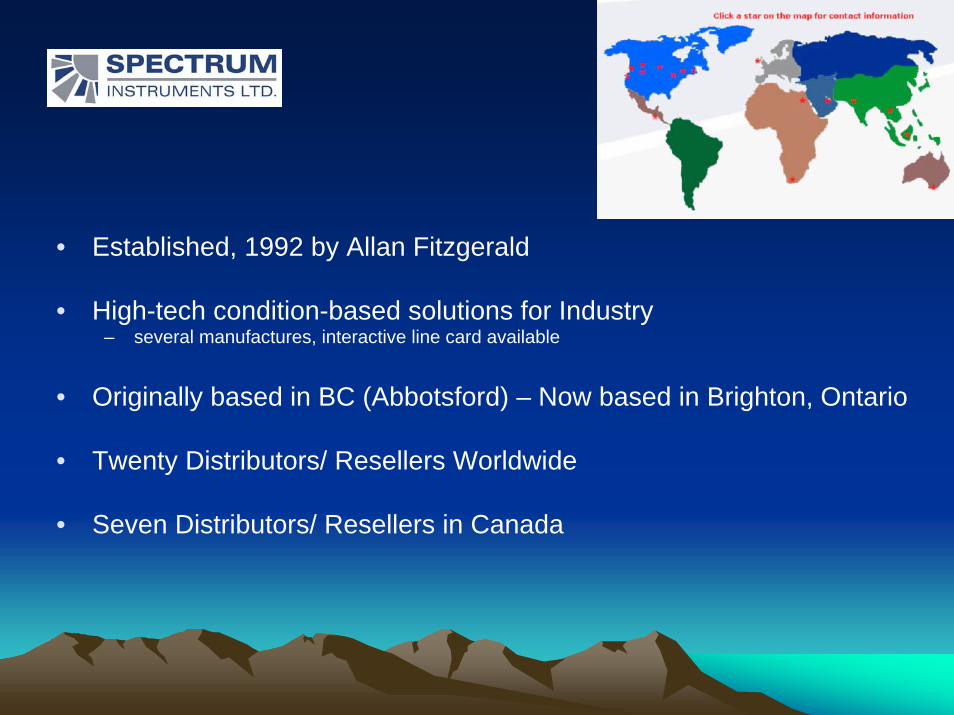
• Established, 1992 by Allan Fitzgerald
• High-tech condition-based solutions for Industry– several manufactures, interactive line card available
• Originally based in BC (Abbotsford) – Now based in Brighton, Ontario
• Twenty Distributors/ Resellers Worldwide
• Seven Distributors/ Resellers in Canada

WWIRELESS IRELESS AASSET SSET MMONITORINGONITORING
MANUFACTURING DIVISION – UPTIME SOLUTIONSDivision headquarters in Jacksonville, FL and a Design center in Austin, TX.
Austin, TexasJacksonville, Florida
Spectrum Contact:Wes Dettwiler: 519-585-7972
Distributor Contact:Andy Woodcock: 416 9383493
Uptime Solutions Division Uptime Solutions Division –– Key PersonnelKey PersonnelTechnology……(Jim Girardeau)25 years industry experience in advanced speed signal processingSpecialist in RF and radio communicationAdvanced training in engineering and project managementHas managed multiple large projects spanning across multiple remote sites.M.S. Degree in Electrical Engineering
Industry…..(Tim Rohrer)20 years experience in the Pulp and Paper industry3 years wireless system experience (installing, training, trouble shooting)Assisted in designing, and testing wireless vibration systemsBS. Degree in Geology with a minor in Computer Graphics3 years wireless/vibration monitoring software training
Uptime Solutions Uptime Solutions Company Vision:• Use the latest technology, to develop new solutions to
old problems.
• Commitment- To produce high quality products that reach beyond customer expectations that are reliable, consistent and competitively priced.
• 2010 WAM Product Goals– Introduce 1 new WAM product per quarter
Current ProductsCurrent Products• WAM-661 Transmitter Node
• WAM-2 Transceiver Base Station
• Translator (Data transfer into other PdM Programs)
• TC 1 Thermal Amplifier (Thermocouple Amplifier for WAM)
• Pathfinder Condition Monitoring Software suite
• WAM-761 WAM Node (Currently in Beta Testing)
• REO Sentinel (Portable monitor for the transport industry)
Future Products PlannedFuture Products Planned• 35 Channel Wireless Box (Q4 2010)
– 32 Simultaneous inputs plus Tachs– Ethernet Capabilities
• Wireless Camera (Q1 2011)
• Wireless Accelerometer (Q2 2011)– Range– Battery life
• Wireless Data Collector (Q3 2011)
WAM System ComponentsWAM System Components1. Input Sensors and sensor cables2. Transmitting Nodes3. Transceivers – Receiving Base Stations
4. Software Included: - dB Editor- On Line Monitor- Pathfinder PdM
5. Translator (Optional) – Data transfer into other PdM programs
6. Software Gateways (Optional) - OPC and/or PI Historian
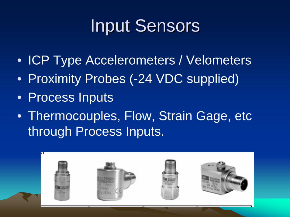
Input SensorsInput Sensors
• ICP Type Accelerometers / Velometers• Proximity Probes (-24 VDC supplied)• Process Inputs• Thermocouples, Flow, Strain Gage, etc
through Process Inputs.
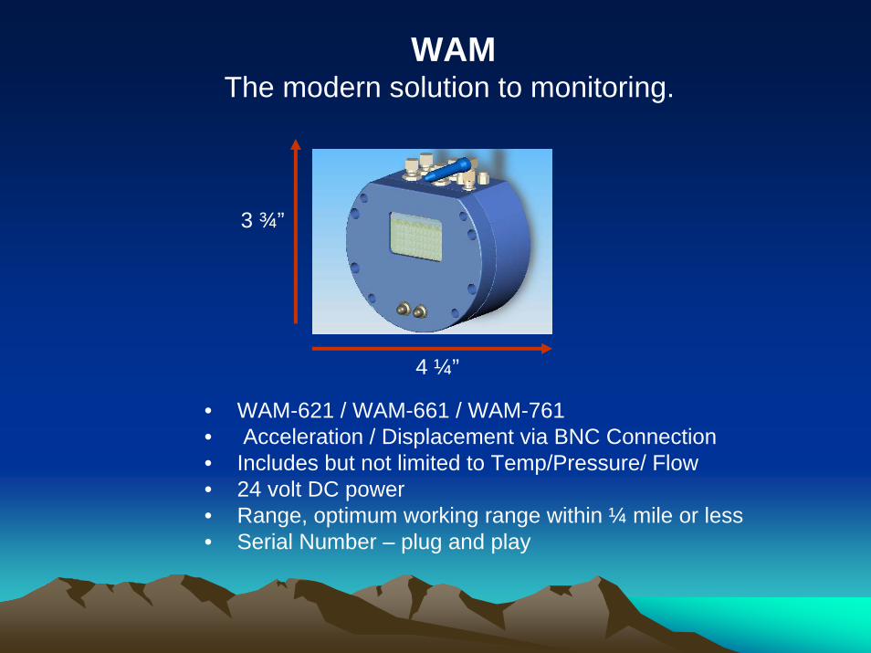
WAMThe modern solution to monitoring.
3 ¾”
4 ¼”
• WAM-621 / WAM-661 / WAM-761• Acceleration / Displacement via BNC Connection• Includes but not limited to Temp/Pressure/ Flow • 24 volt DC power• Range, optimum working range within ¼ mile or less• Serial Number – plug and play
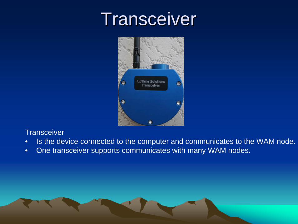
TransceiverTransceiver
Transceiver• Is the device connected to the computer and communicates to the WAM node.• One transceiver supports communicates with many WAM nodes.
SoftwareSoftware
• Pathfinder– database– analysis– reporting– exporting capabilities
Standard SoftwareStandard Software• Pathfinder Software License
– unlimited number of seats– based upon the Canada Post Mailing Address
• PI Historian Gtateway– “process information” real-time data historian– allows for viewing of real-time and look back at data from years ago
• OPC interfacing– Open Connectivity– Current and emerging OPC Specifications include:
• Data access, alarms and events, batch, data exchange, historical access, security, xml-da, complex, commands, unified architecture
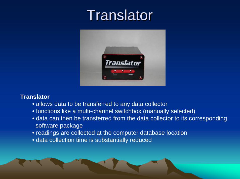
TranslatorTranslator
Translator• allows data to be transferred to any data collector• functions like a multi-channel switchbox (manually selected)• data can then be transferred from the data collector to its correspondingsoftware package
• readings are collected at the computer database location• data collection time is substantially reduced
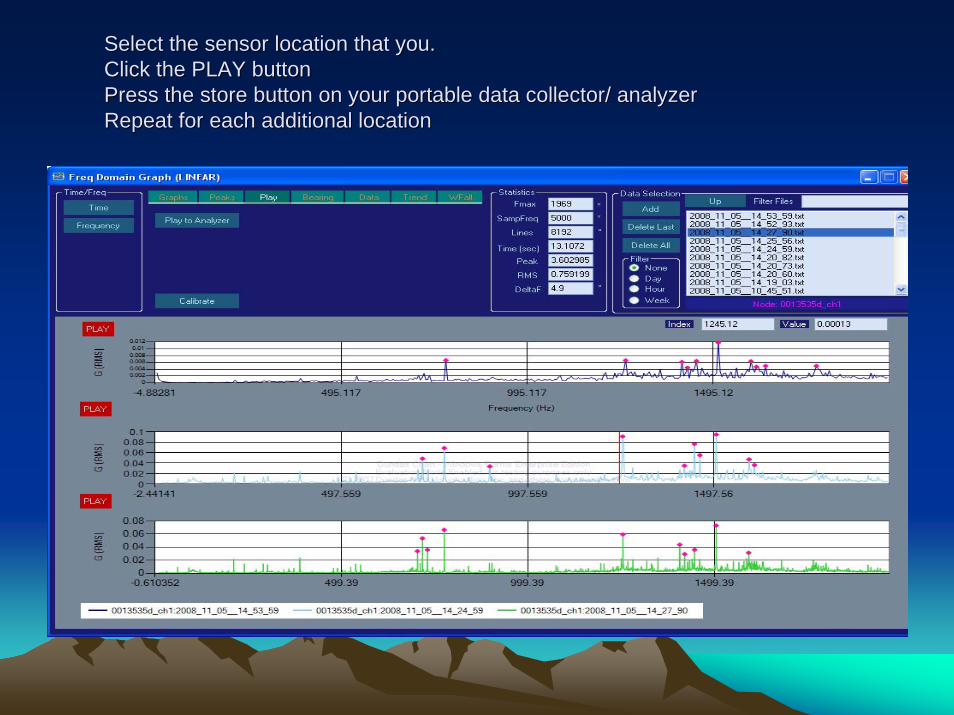
Select the sensor location that you.Select the sensor location that you.Click the PLAY button Click the PLAY button Press the store button on your portable data collector/ analyzerPress the store button on your portable data collector/ analyzerRepeat for each additional locationRepeat for each additional location
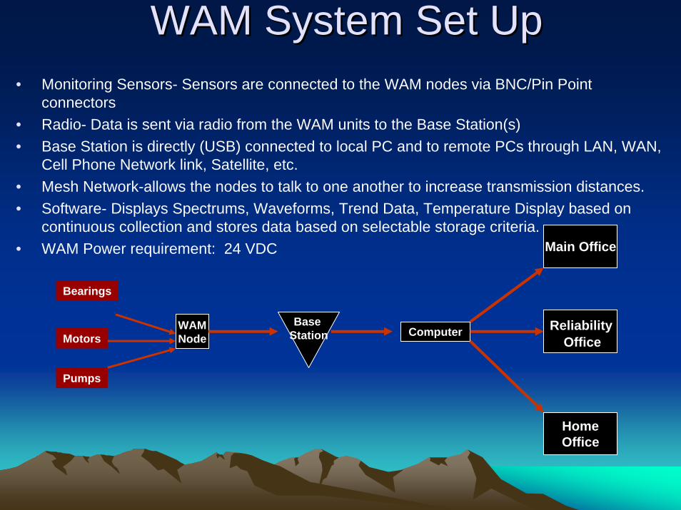
WAM System Set UpWAM System Set Up• Monitoring Sensors- Sensors are connected to the WAM nodes via BNC/Pin Point
connectors • Radio- Data is sent via radio from the WAM units to the Base Station(s)• Base Station is directly (USB) connected to local PC and to remote PCs through LAN, WAN,
Cell Phone Network link, Satellite, etc.• Mesh Network-allows the nodes to talk to one another to increase transmission distances.• Software- Displays Spectrums, Waveforms, Trend Data, Temperature Display based on
continuous collection and stores data based on selectable storage criteria. • WAM Power requirement: 24 VDC
HomeOffice
Base Station
Main Office
ComputerWAMNode
Reliability Office
Bearings
Motors
Pumps
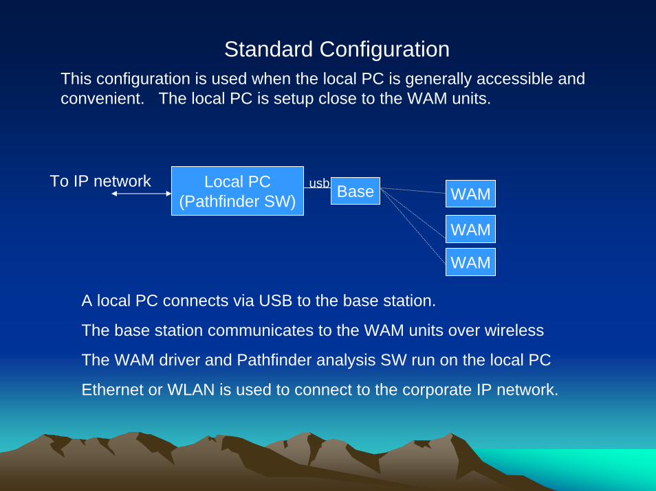
Standard Configuration This configuration is used when the local PC is generally accessible and convenient. The local PC is setup close to the WAM units.
Local PC(Pathfinder SW) Baseusb
WAM
WAM
WAM
To IP network
A local PC connects via USB to the base station.
The base station communicates to the WAM units over wireless
The WAM driver and Pathfinder analysis SW run on the local PC
Ethernet or WLAN is used to connect to the corporate IP network.
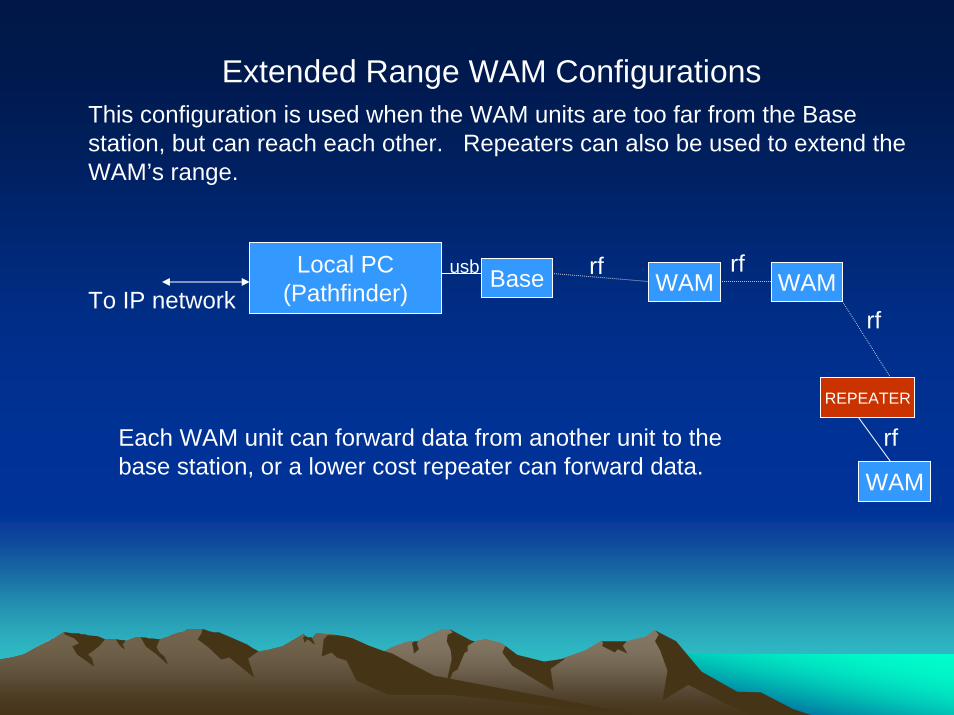
Extended Range WAM Configurations This configuration is used when the WAM units are too far from the Base station, but can reach each other. Repeaters can also be used to extend the WAM’s range.
Local PC(Pathfinder) Baseusb
WAM WAM
REPEATER
To IP network
Each WAM unit can forward data from another unit to the base station, or a lower cost repeater can forward data. WAM
rf
rf
rf
rf
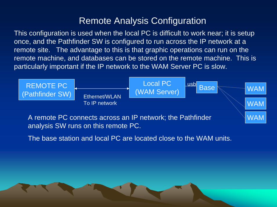
Remote Analysis Configuration This configuration is used when the local PC is difficult to work near; it is setup once, and the Pathfinder SW is configured to run across the IP network at a remote site. The advantage to this is that graphic operations can run on the remote machine, and databases can be stored on the remote machine. This is particularly important if the IP network to the WAM Server PC is slow.
Local PC(WAM Server) Baseusb
WAM
WAM
WAM
REMOTE PC(Pathfinder SW) Ethernet/WLAN
To IP network
A remote PC connects across an IP network; the Pathfinder analysis SW runs on this remote PC.
The base station and local PC are located close to the WAM units.
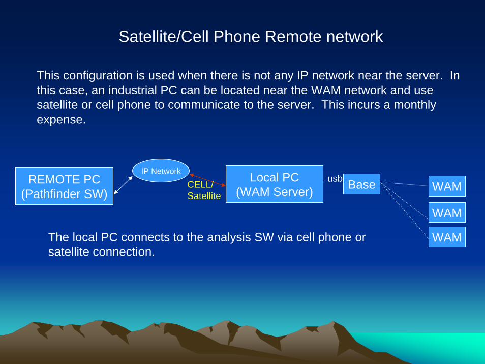
Satellite/Cell Phone Remote network
Local PC(WAM Server) Baseusb
WAM
WAM
WAM
CELL/Satellite
REMOTE PC(Pathfinder SW)
This configuration is used when there is not any IP network near the server. In this case, an industrial PC can be located near the WAM network and use satellite or cell phone to communicate to the server. This incurs a monthly expense.
IP Network
The local PC connects to the analysis SW via cell phone or satellite connection.
Summary
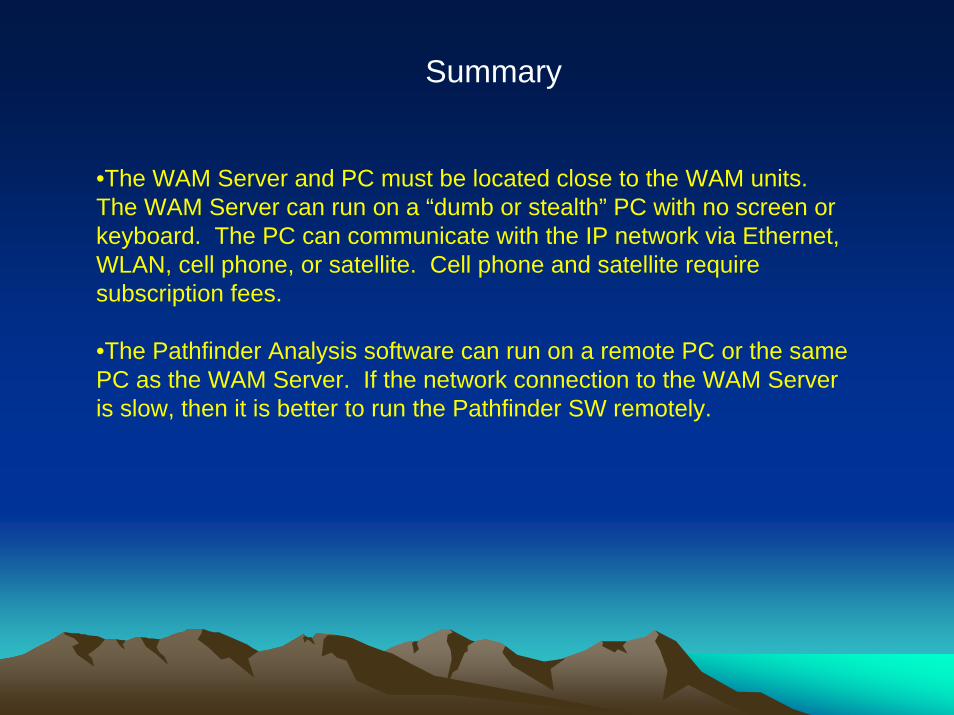
•The WAM Server and PC must be located close to the WAM units. The WAM Server can run on a “dumb or stealth” PC with no screen or keyboard. The PC can communicate with the IP network via Ethernet, WLAN, cell phone, or satellite. Cell phone and satellite require subscription fees.
•The Pathfinder Analysis software can run on a remote PC or the same PC as the WAM Server. If the network connection to the WAM Server is slow, then it is better to run the Pathfinder SW remotely.
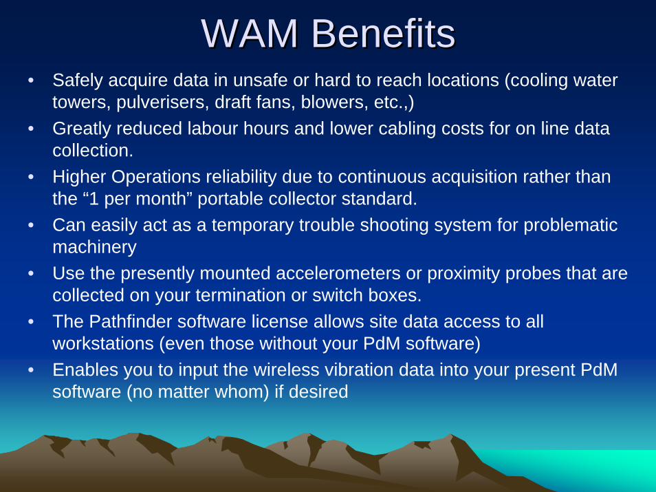
WAM BenefitsWAM Benefits• Safely acquire data in unsafe or hard to reach locations (cooling water
towers, pulverisers, draft fans, blowers, etc.,)• Greatly reduced labour hours and lower cabling costs for on line data
collection.• Higher Operations reliability due to continuous acquisition rather than
the “1 per month” portable collector standard.• Can easily act as a temporary trouble shooting system for problematic
machinery• Use the presently mounted accelerometers or proximity probes that are
collected on your termination or switch boxes.• The Pathfinder software license allows site data access to all
workstations (even those without your PdM software)• Enables you to input the wireless vibration data into your present PdM
software (no matter whom) if desired
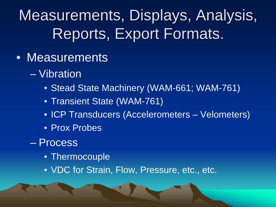
Measurements, Displays, Analysis, Measurements, Displays, Analysis, Reports, Export Formats.Reports, Export Formats.
• Measurements– Vibration
• Stead State Machinery (WAM-661; WAM-761)• Transient State (WAM-761)• ICP Transducers (Accelerometers – Velometers)• Prox Probes
– Process• Thermocouple• VDC for Strain, Flow, Pressure, etc., etc.
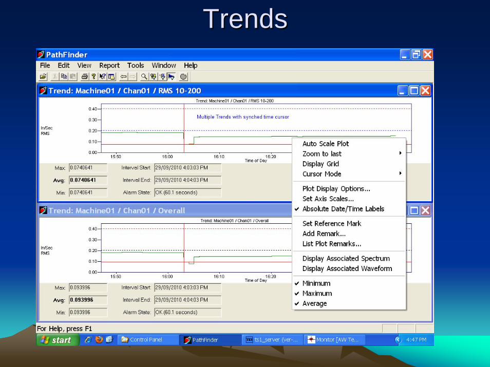
TrendsTrends
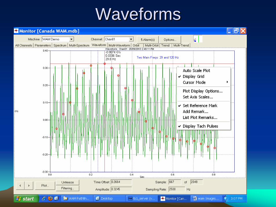
WaveformsWaveforms
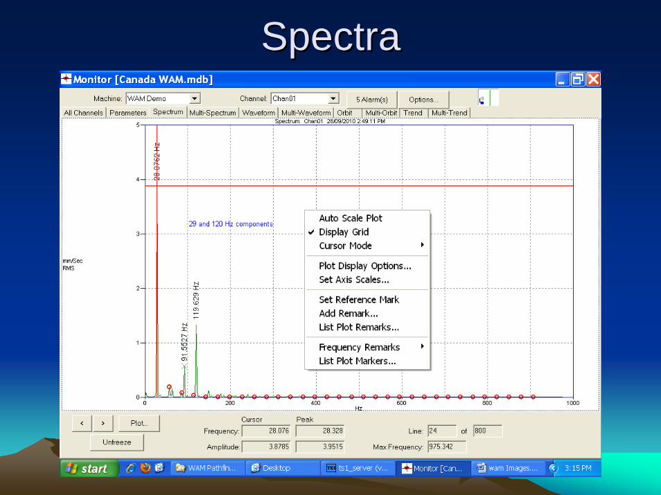
SpectraSpectra
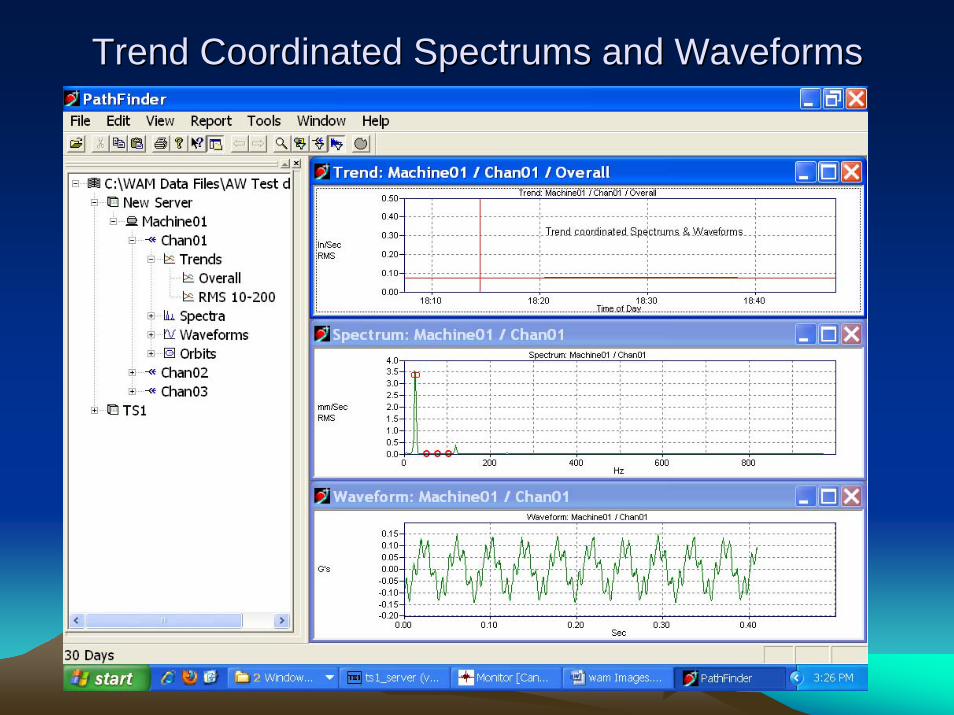
Trend Coordinated Spectrums and WaveformsTrend Coordinated Spectrums and Waveforms
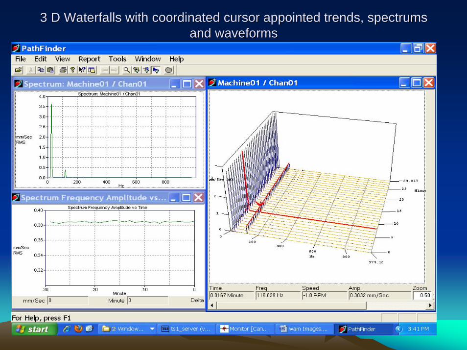
3 D Waterfalls with coordinated cursor appointed trends, spectru3 D Waterfalls with coordinated cursor appointed trends, spectrums ms and waveformsand waveforms
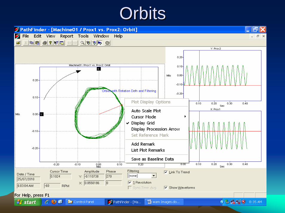
OrbitsOrbits
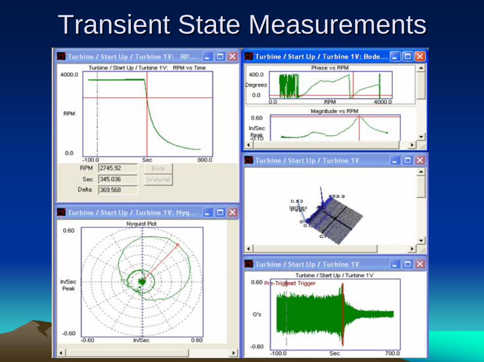
Transient State MeasurementsTransient State Measurements
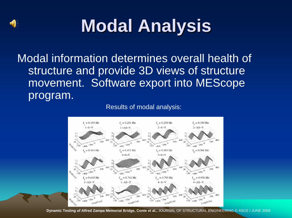
Modal AnalysisModal AnalysisModal information determines overall health of
structure and provide 3D views of structure movement. Software export into MEScope program.
Dynamic Testing of Alfred Zampa Memorial Bridge, Conte et al., JOURNAL OF STRUCTURAL ENGINEERING © ASCE / JUNE 2008
Results of modal analysis:
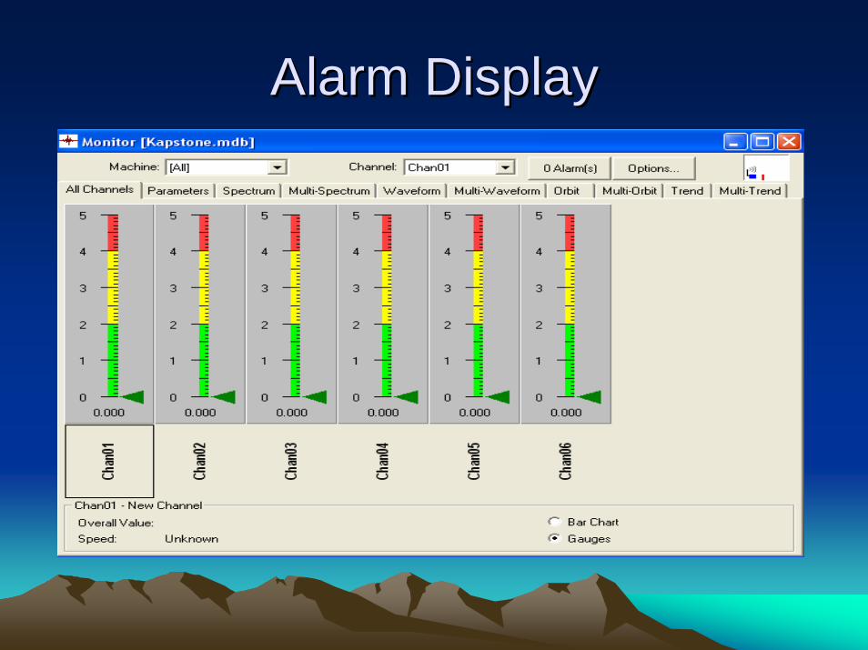
Alarm DisplayAlarm Display
ReportsReports• Latest Measurement
– Based on overall– Based on frequency
• Scheduled– Weekly, monthly
• Alarm– Overall– Spectra
• Alerts– Email
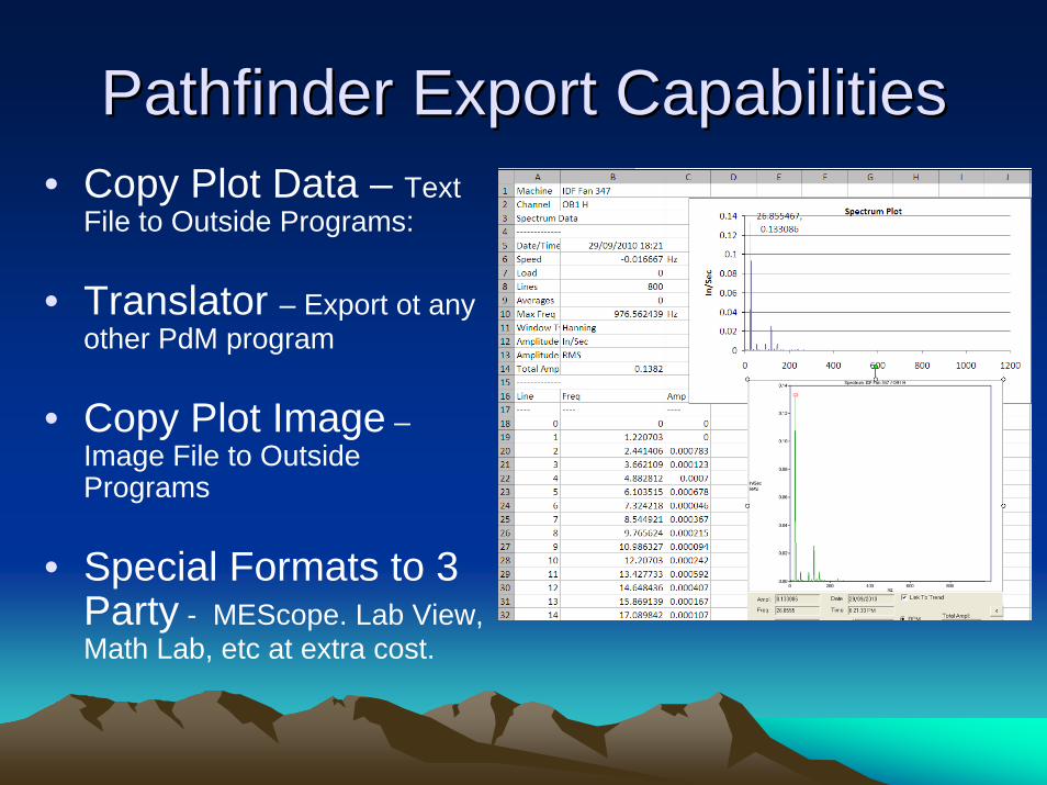
Pathfinder Export CapabilitiesPathfinder Export Capabilities• Copy Plot Data – Text
File to Outside Programs:
• Translator – Export ot any other PdM program
• Copy Plot Image –Image File to Outside Programs
• Special Formats to 3 Party - MEScope. Lab View, Math Lab, etc at extra cost.
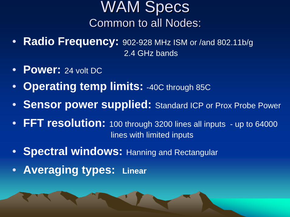
WAM SpecsWAM SpecsCommon to all Nodes:Common to all Nodes:
• Radio Frequency: 902-928 MHz ISM or /and 802.11b/g2.4 GHz bands
• Power: 24 volt DC
• Operating temp limits: -40C through 85C
• Sensor power supplied: Standard ICP or Prox Probe Power
• FFT resolution: 100 through 3200 lines all inputs - up to 64000 lines with limited inputs
• Spectral windows: Hanning and Rectangular
• Averaging types: Linear
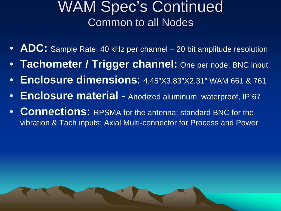
WAM SpecWAM Spec’’s Continueds ContinuedCommon to all NodesCommon to all Nodes
• ADC: Sample Rate 40 kHz per channel – 20 bit amplitude resolution
• Tachometer / Trigger channel: One per node, BNC input
• Enclosure dimensions: 4.45”X3.83”X2.31” WAM 661 & 761
• Enclosure material - Anodized aluminum, waterproof, IP 67
• Connections: RPSMA for the antenna; standard BNC for the vibration & Tach inputs; Axial Multi-connector for Process and Power
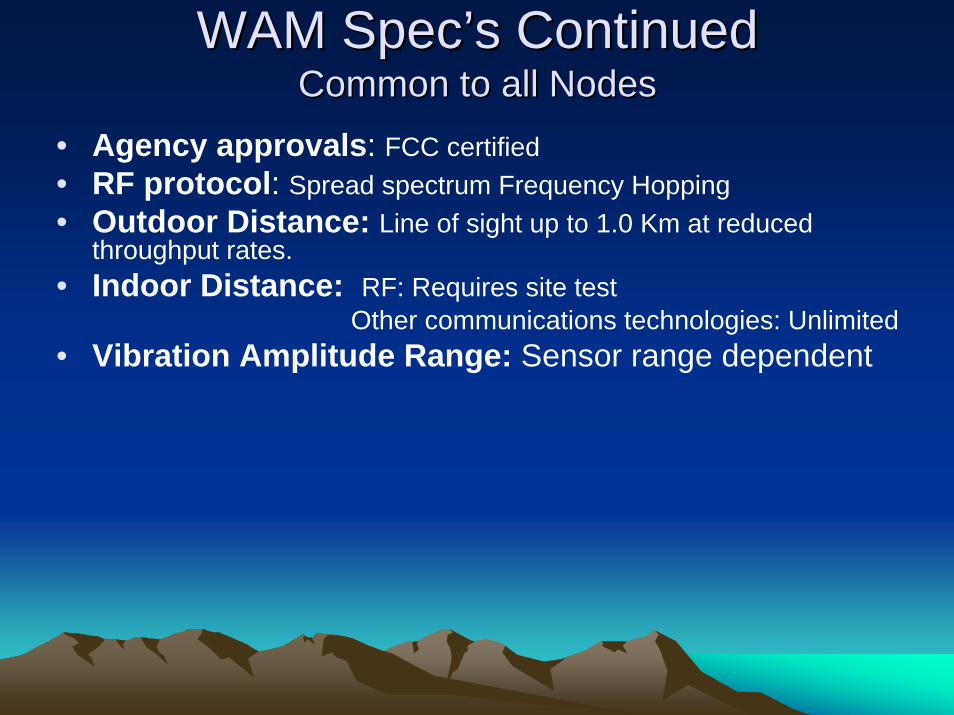
WAM SpecWAM Spec’’s Continueds ContinuedCommon to all NodesCommon to all Nodes
• Agency approvals: FCC certified• RF protocol: Spread spectrum Frequency Hopping• Outdoor Distance: Line of sight up to 1.0 Km at reduced
throughput rates.• Indoor Distance: RF: Requires site test
Other communications technologies: Unlimited• Vibration Amplitude Range: Sensor range dependent
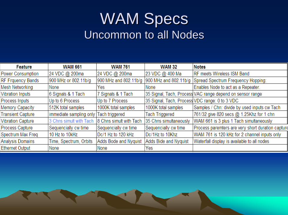
WAM SpecsWAM SpecsUncommon to all NodesUncommon to all Nodes

Pathfinder Analysis ParametersPathfinder Analysis Parameters• Waveform RMS: The Root Mean Squared of all amplitude values in the waveform. This is a
good overall vibration level indicator.• Waveform Peak: The highest individual absolute value found in the waveform. This is a good
way to detect impacting.• Waveform Peak to Peak: The distance between the highest value and the lowest value in the
waveform. This is a good way to detect impacts that cause spikes in both directions.• Waveform Crest Factor: This is the ratio of waveform peak to RMS. This is a good way to
detect the relative strength of impacting compared to the rest of the vibration signal.• Total Spectral Energy: This is the Root Sum Squared of all amplitudes in the power
spectrum. This yields results similar to Waveform RMS, but it allows you to select any amplitude factor (RMS, Peak, or Peak to Peak).
• Spectral Band: This is the Root Sum Squared of the amplitudes within a specified frequency range of the spectrum. This is probably the most useful parameter type, since it can detect any fault that causes increased vibration at a known frequency. The frequency range can be specified in Hz, CPM, or even Orders (1 order = tachometer speed). This parameter type also allows software integration of amplitudes (e.g. converting acceleration to velocity). Integration is not recommended for bands including low frequencies (5 Hz or less) because the integration process can cause even small amounts of noise at these frequencies to be amplified to very high levels.
• Tachometer Speed: This is the speed of the measurement point's tachometer. Having this as an analysis parameter allows you to view trends of speed over time.
• Peak Amplitude: This is the 'true peak' amplitude at a specified frequency in orders. This can be used to detect unbalance, and makes a good complement to a Peak Phase parameter at the same frequency.
• Peak Phase: This is the phase (measured against direction of rotation) associated with the 'true peak' at a specified frequency in orders.
• Bias/Gap Voltage: This is the DC component of the vibration signal. For displacement probes, this represents the 'gap' between the probe and the machine surface it is measuring. For accelerometers powered by the PATHFINDER system, this represents the 'bias' voltage. Bias voltage should typically be in the neighborhood of +12V. Values near 0V or +24V indicate a sensor or wiring failure. Note that measuring this type of parameter requires switching the system from AC mode to DC mode (just like reading from process channels) and can cause problems with transient data capture.
OptionsOptions
• Hardwired WAM’s are Available – Ethernet – RS-232 – RS-485
• Via cell IP networking for remote sites
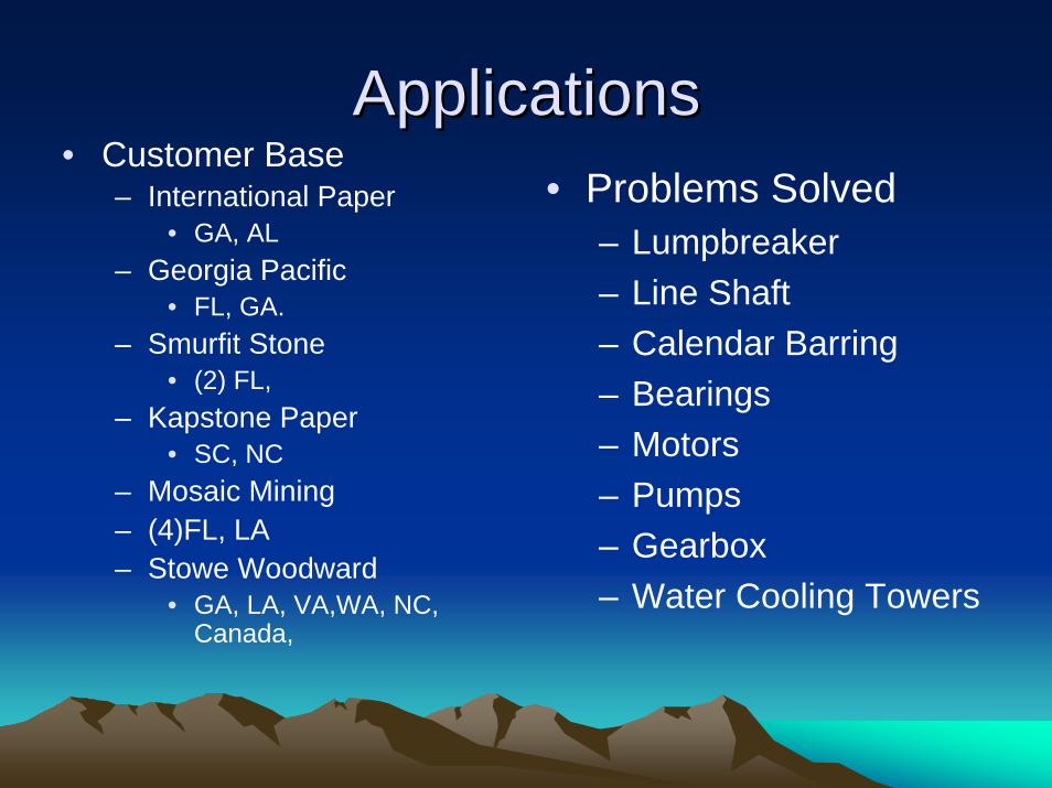
ApplicationsApplications• Customer Base
– International Paper• GA, AL
– Georgia Pacific• FL, GA.
– Smurfit Stone• (2) FL,
– Kapstone Paper• SC, NC
– Mosaic Mining– (4)FL, LA– Stowe Woodward
• GA, LA, VA,WA, NC, Canada,
• Problems Solved– Lumpbreaker– Line Shaft– Calendar Barring– Bearings– Motors– Pumps– Gearbox– Water Cooling Towers
ApplicationsApplications
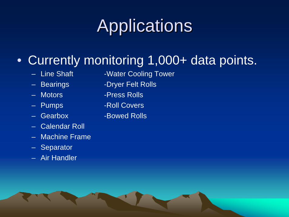
• Currently monitoring 1,000+ data points.– Line Shaft -Water Cooling Tower– Bearings -Dryer Felt Rolls– Motors -Press Rolls– Pumps -Roll Covers– Gearbox -Bowed Rolls– Calendar Roll– Machine Frame– Separator– Air Handler

Paper Machine InstallationPaper Machine Installation
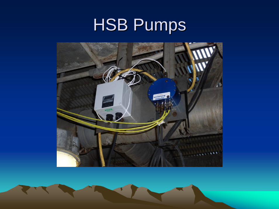
HSB PumpsHSB Pumps
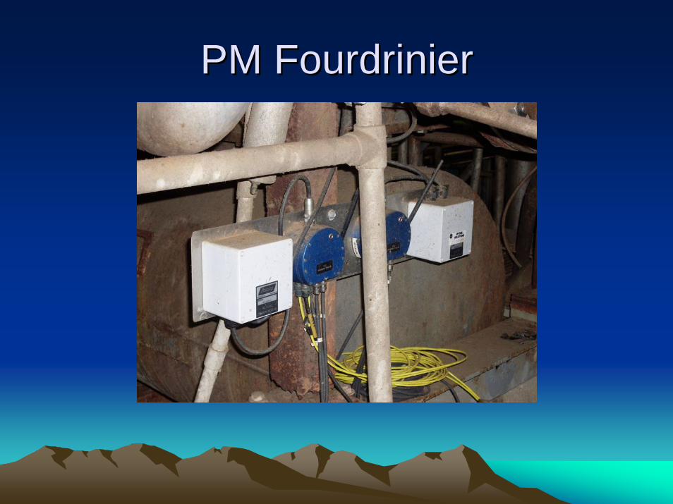
PM PM FourdrinierFourdrinier

Applications
• Mobile Equipment– Mining
• Heavy haulers
– Steel• Cranes
– Temporary Trouble Shooting

Reference ContactsReference Contacts
• Kapstone Paper• Smurfit Stone• International Paper• Allied Reliability• Stowe Woodward

BenefitsBenefits
Reduced DowntimeLabor Saving
SAVING MONEY & TIME!!!
Demonstration System:Demonstration System:On On Site at OPG Kipling Office, Thursday Sept 30Site at OPG Kipling Office, Thursday Sept 30thth after Lunchafter Lunch

• Thank you very much for your attendance