Embed Size (px)
Citation preview
Opportunities and Incentives for CHP in
Massachusetts
Interconnection Procedures
June 19, 2013Tim Roughan
Agenda
• MA interconnection process
• Federal Energy Regulatory Commission (FERC) interconnection process at ISO-NE
• Appendix – Technical considerations
• Appendix – Net metering in MA
Safety Moment
• This morning’s session provides a great safety moment.– All the benefits derived from Distributed
Generation quickly lose their value if someone is injured as a result of an improper interconnection.
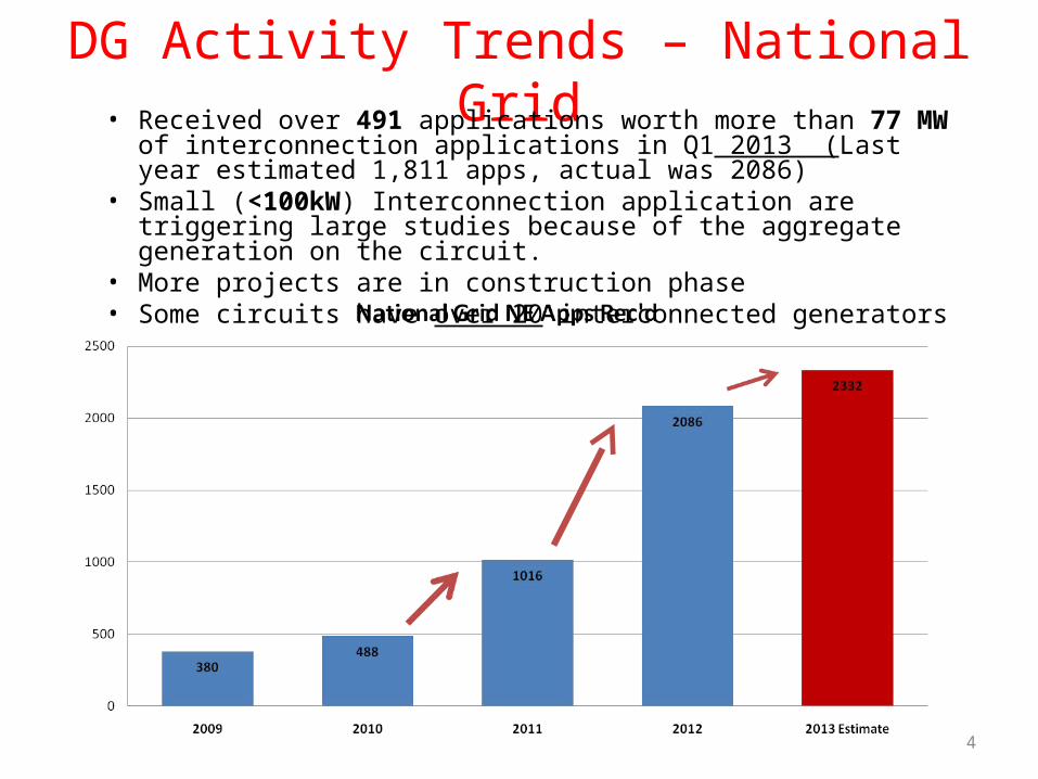
DG Activity Trends – National Grid• Received over 491 applications worth more than 77 MW of interconnection
applications in Q1 2013 (Last year estimated 1,811 apps, actual was 2086)• Small (<100kW) Interconnection application are triggering large studies
because of the aggregate generation on the circuit.• More projects are in construction phase• Some circuits have over 20 interconnected generators
4
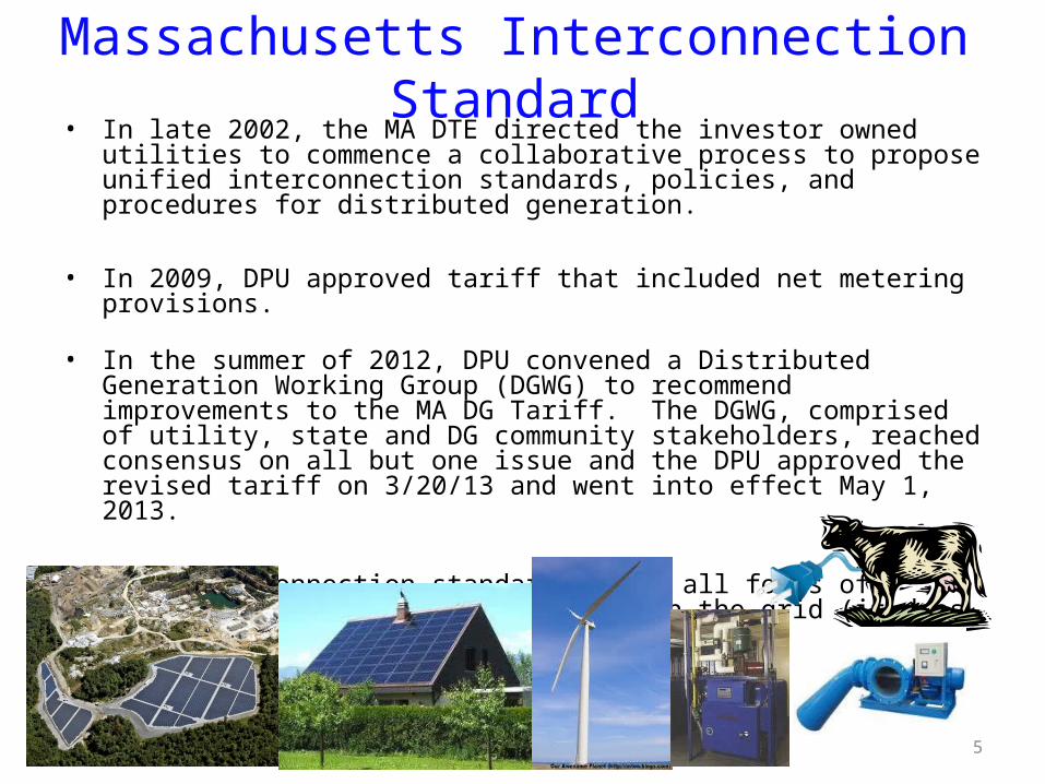
Massachusetts Interconnection Standard• In late 2002, the MA DTE directed the investor owned utilities to commence a
collaborative process to propose unified interconnection standards, policies, and procedures for distributed generation.
• In 2009, DPU approved tariff that included net metering provisions.
• In the summer of 2012, DPU convened a Distributed Generation Working Group (DGWG) to recommend improvements to the MA DG Tariff. The DGWG, comprised of utility, state and DG community stakeholders, reached consensus on all but one issue and the DPU approved the revised tariff on 3/20/13 and went into effect May 1, 2013.
• This interconnection standard covers all forms of generation operating in parallel with the grid (it does not apply to emergency generation).
5
What is the Interconnection Process?
• Process of getting an interconnection agreement from your local utility (or distribution company) to connect a distributed generation system to their distribution system.
• This process is used by the four investor owned utilities (IOU) in Massachusetts (NSTAR, National Grid, Unitil and Western Mass Electric)
• Municipally-owned utilities are not required to follow this process, and may follow a different criteria.
• The process is used to make sure interconnecting DG systems are integrated into the distribution system responsibly with respect to impacts on reliability, power quality and safety • Can not allow DG to affect neighbors on feeder
6
Importance of the Interconnection Process for CHP
• Following the interconnection process is important because a DG system changes the one-way power flow from the utility to customer, which can present dangers to utility workers if proper equipment is not installed
• While robust and capable of handling minor disturbances, the quality of grid power is extremely important. The interconnection process ensures the DG meets safety, reliability, & power quality requirements with regard to:• Islanding• Transient Voltage Conditions• Noise and Harmonics• Frequency• Voltage Level• Machine Reactive Capability
• It is essential that each interconnection get an interconnection agreement with the utility before installing any generation. You are proceeding at your own risk if you choose to install a system without utility approval.
7
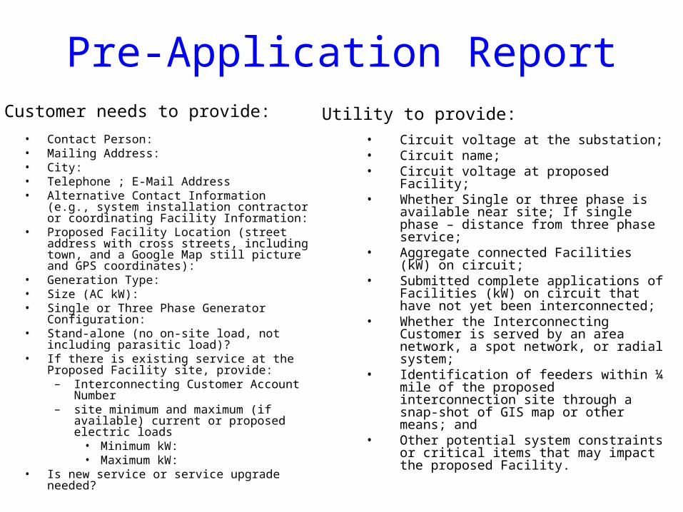
Pre-Application Report
• Contact Person: • Mailing Address:• City: • Telephone ; E-Mail Address• Alternative Contact Information (e.g., system
installation contractor or coordinating Facility Information:
• Proposed Facility Location (street address with cross streets, including town, and a Google Map still picture and GPS coordinates):
• Generation Type: • Size (AC kW): • Single or Three Phase Generator Configuration: • Stand-alone (no on-site load, not including
parasitic load)?• If there is existing service at the Proposed
Facility site, provide:– Interconnecting Customer Account
Number – site minimum and maximum (if available)
current or proposed electric loads• Minimum kW: • Maximum kW:
• Is new service or service upgrade needed?
• Circuit voltage at the substation;• Circuit name;• Circuit voltage at proposed Facility;• Whether Single or three phase is available
near site; If single phase – distance from three phase service;
• Aggregate connected Facilities (kW) on circuit;
• Submitted complete applications of Facilities (kW) on circuit that have not yet been interconnected;
• Whether the Interconnecting Customer is served by an area network, a spot network, or radial system;
• Identification of feeders within ¼ mile of the proposed interconnection site through a snap-shot of GIS map or other means; and
• Other potential system constraints or critical items that may impact the proposed Facility.
Customer needs to provide: Utility to provide:
9
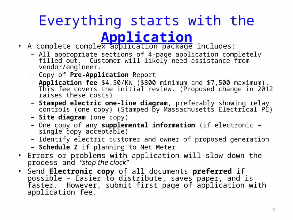
Everything starts with the Application• A complete complex application package includes:
– All appropriate sections of 4-page application completely filled out. Customer will likely need assistance from vendor/engineer.
– Copy of Pre-Application Report– Application fee $4.50/KW ($300 minimum and $7,500 maximum). This fee
covers the initial review. (Proposed change in 2012 raises these costs)– Stamped electric one-line diagram, preferably showing relay controls (one
copy) (Stamped by Massachusetts Electrical PE)– Site diagram (one copy)– One copy of any supplemental information (if electronic – single copy
acceptable)– Identify electric customer and owner of proposed generation– Schedule Z if planning to Net Meter
• Errors or problems with application will slow down the process and “stop the clock”
• Send Electronic copy of all documents preferred if possible – Easier to distribute, saves paper, and is faster. However, submit first page of application with application fee.

• Applies to:• Single phase customers with listed single-phase inverter
based systems >15 kW on a radial feed• Three phase customers with listed three-phase inverter
based systems >25kW on a radial feed.• Maximum size is based on review of screens
• Does not Apply to:• Non-listed inverters or other generators (induction /
synchronous / asynchronous)• Aggregate generation capacity of listed inverters that exceed
the above-mentioned limits
Expedited Review Path
10
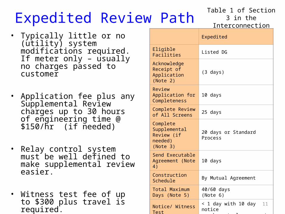
Expedited Review Path• Typically little or no (utility) system
modifications required. If meter only – usually no charges passed to customer
• Application fee plus any Supplemental Review charges up to 30 hours of engineering time @ $150/hr (if needed)
• Relay control system must be well defined to make supplemental review easier.
• Witness test fee of up to $300 plus travel is required.
Table 1 of Section 3 in the Interconnection Tariff
11
Expedited
Eligible Facilities Listed DG
Acknowledge Receipt of Application (Note 2)
(3 days)
Review Application for Completeness
10 days
Complete Review of All Screens
25 days
Complete Supplemental Review (if needed)(Note 3)
20 days or Standard Process
Send Executable Agreement (Note 4)
10 days
Construction Schedule
By Mutual Agreement
Total Maximum Days (Note 5)
40/60 days(Note 6)
Notice/ Witness Test
< 1 day with 10 day notice or by mutual agreement

12
Supplemental Review• If one or more Screens are not passed, the Company will provide a Supplemental Review
Agreement. • Threshold is whether project is less than 67% of minimum load on the feeder
– Then other screens review voltage quality , reliability and safety to reduce the potential need for impact studies.
– DPU order allowed for the 67% screen, but requires utilities to document how the use of a 100% screen would change the screening process
• Customer signs agreement and pays fee for additional engineering time (max fee is now $4,500).
• The Supplemental Review may be able to determine what impacts the generation system will have and what (if any) modifications are required. If so - an interconnection agreement will be sent to customer detailing:
– System modification requirements, reasoning, and costs for these modifications– Specifics on protection requirements as necessary
• If Supplemental Review cannot determine requirements, an Impact Study Agreement (or equal) will be sent to the customer. (You shift to the Standard Process.)

• Applies to:• Non-listed inverters or other generators:
• Induction• Synchronous• Asynchronous
• Other large MW and Multi MW Projects• Renewable DG Customers / Developers
Standard Review Path
13
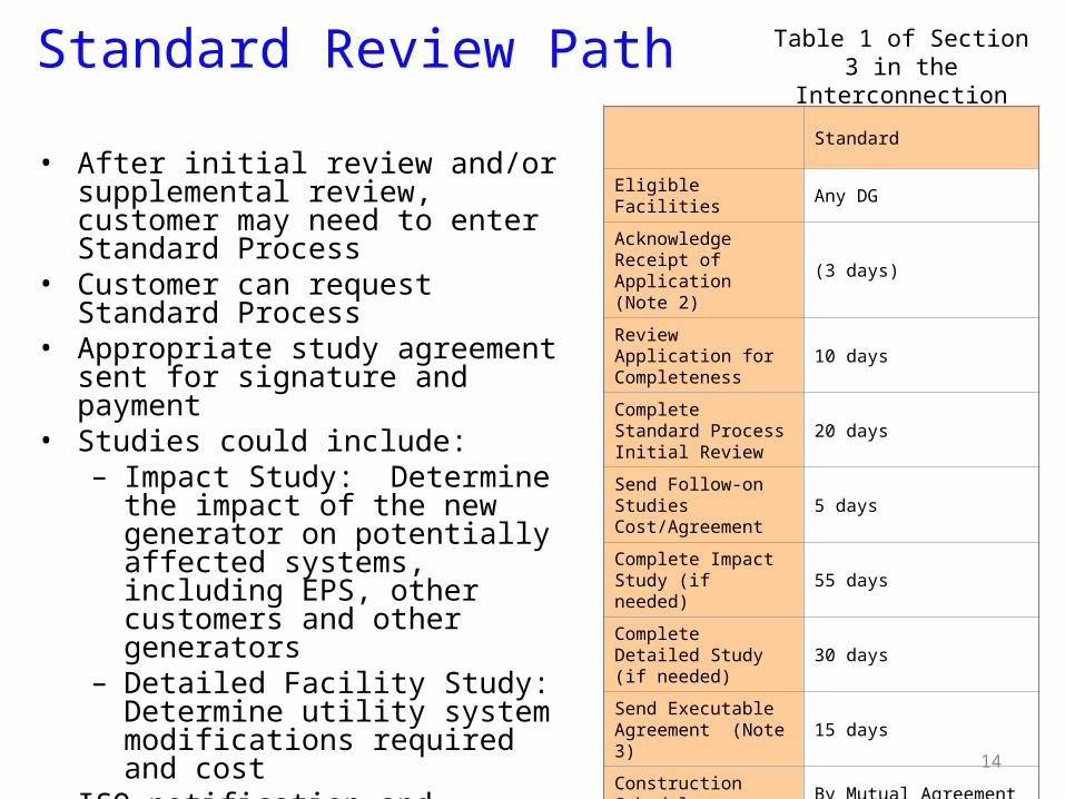
Standard Review Path Table 1 of Section 3 in the Interconnection Tariff
• After initial review and/or supplemental review, customer may need to enter Standard Process
• Customer can request Standard Process• Appropriate study agreement sent for
signature and payment• Studies could include:
– Impact Study: Determine the impact of the new generator on potentially affected systems, including EPS, other customers and other generators
– Detailed Facility Study: Determine utility system modifications required and cost
• ISO notification and possibly Transmission Study if over 1 MW
• After studies – interconnection agreement sent for signature
• Witness test fee is actual cost. 14
Standard
Eligible Facilities Any DG
Acknowledge Receipt of Application(Note 2)
(3 days)
Review Application for Completeness
10 days
Complete Standard Process Initial Review
20 days
Send Follow-on Studies Cost/Agreement
5 days
Complete Impact Study (if needed)
55 days
Complete Detailed Study (if needed)
30 days
Send Executable Agreement (Note 3)
15 days
Construction Schedule
By Mutual Agreement
Total Maximum Days (Note 4)
125/150 days(Note 5)
Notice/ Witness Test
10 days or by mutual agreement
15
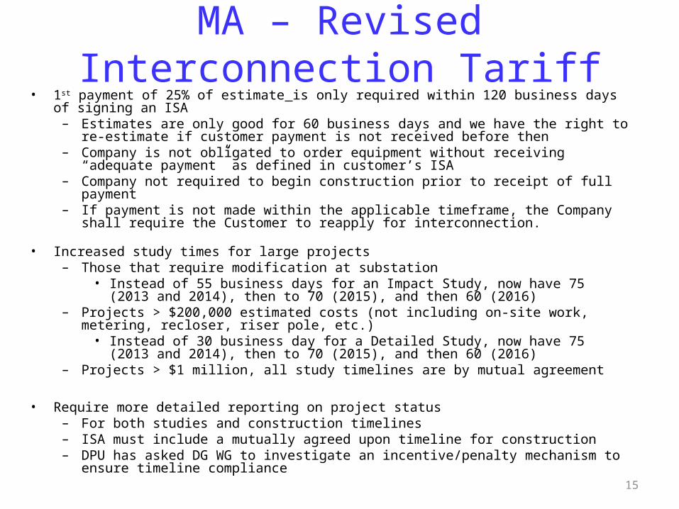
MA – Revised Interconnection Tariff• 1st payment of 25% of estimate is only required within 120 business days of signing an ISA
– Estimates are only good for 60 business days and we have the right to re-estimate if customer payment is not received before then
– Company is not obligated to order equipment without receiving “adequate payment” as defined in customer’s ISA
– Company not required to begin construction prior to receipt of full payment – If payment is not made within the applicable timeframe, the Company shall require the
Customer to reapply for interconnection.
• Increased study times for large projects– Those that require modification at substation
• Instead of 55 business days for an Impact Study, now have 75 (2013 and 2014), then to 70 (2015), and then 60 (2016)
– Projects > $200,000 estimated costs (not including on-site work, metering, recloser, riser pole, etc.)
• Instead of 30 business day for a Detailed Study, now have 75 (2013 and 2014), then to 70 (2015), and then 60 (2016)
– Projects > $1 million, all study timelines are by mutual agreement
• Require more detailed reporting on project status– For both studies and construction timelines– ISA must include a mutually agreed upon timeline for construction– DPU has asked DG WG to investigate an incentive/penalty mechanism to ensure timeline
compliance
16
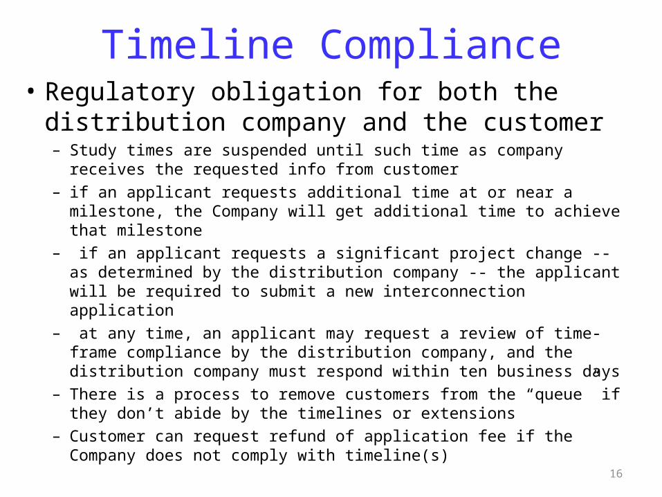
Timeline Compliance• Regulatory obligation for both the distribution
company and the customer– Study times are suspended until such time as company receives the
requested info from customer– if an applicant requests additional time at or near a milestone, the
Company will get additional time to achieve that milestone– if an applicant requests a significant project change -- as determined by
the distribution company -- the applicant will be required to submit a new interconnection application
– at any time, an applicant may request a review of time-frame compliance by the distribution company, and the distribution company must respond within ten business days
– There is a process to remove customers from the “queue” if they don’t abide by the timelines or extensions
– Customer can request refund of application fee if the Company does not comply with timeline(s)
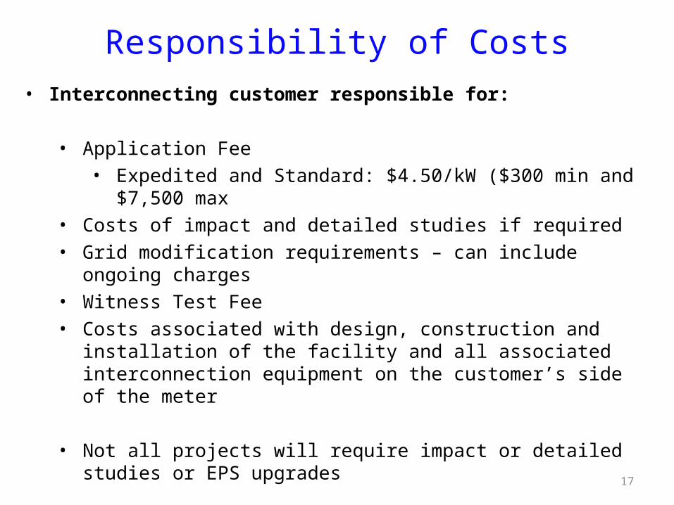
Responsibility of Costs• Interconnecting customer responsible for:
• Application Fee• Expedited and Standard: $4.50/kW ($300 min and $7,500 max
• Costs of impact and detailed studies if required• Grid modification requirements – can include ongoing charges• Witness Test Fee• Costs associated with design, construction and installation of the facility
and all associated interconnection equipment on the customer’s side of the meter
• Not all projects will require impact or detailed studies or EPS upgrades
17
18
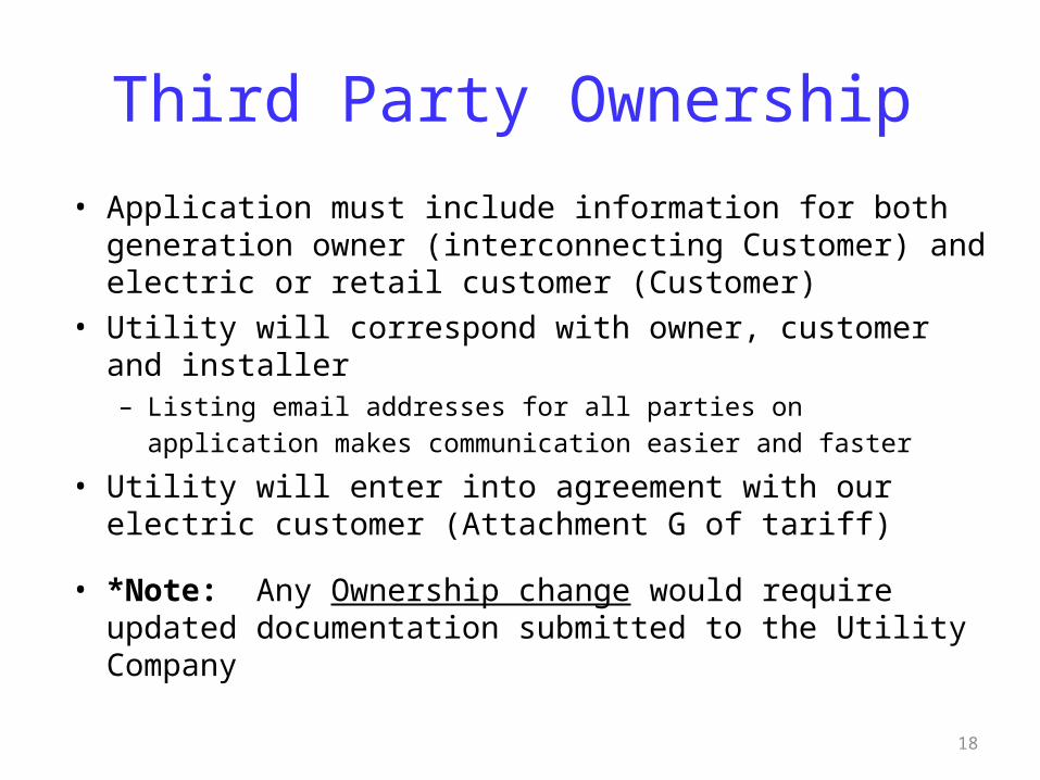
Third Party Ownership
• Application must include information for both generation owner (interconnecting Customer) and electric or retail customer (Customer)
• Utility will correspond with owner, customer and installer– Listing email addresses for all parties on application makes
communication easier and faster • Utility will enter into agreement with our electric customer
(Attachment G of tariff)
• *Note: Any Ownership change would require updated documentation submitted to the Utility Company

19
Common Application Mistakes
• Number of inverters being used not indicated
• Utility account or meter number not included or incorrect
• Address of facility not correct
• Name on application differs from name on utility account
• Application not signed
• Ownership of property not identified
• Not identifying third party ownership of generator
20
Common process delays
• New construction or service upgrade
• Host/Owner misidentification
• Changing inverter or other equipment
• Not supplying electrical permit
• Certificate of Completion (CoC) signed and dated before date given approval to install
21
Behind the scenes at utility…• Review and replacement of metering, modifications to billing• Modifications to protection systems as required (e.g. replace
or install fusing, install switch, modify breaker/recloser set-points, transfer trip, etc.)
• Larger generators require review by NEPOOL reliability committee and registration with ISO-NE
• Adding generation asset to geographic information systems, maps, system one-lines, dispatch systems, etc.
• Publish internal special operating guidelines for utility field personnel on larger generators.
• Set up future testing for relay protection, meter calibration, insurance tracking, etc.
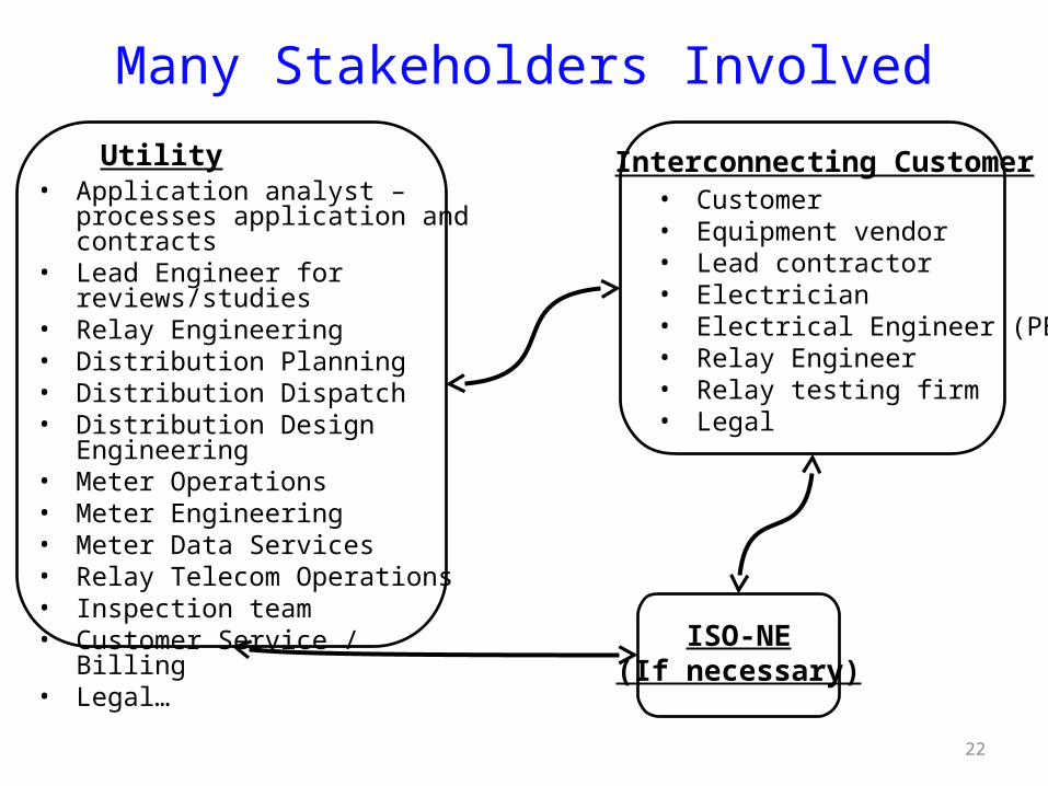
Many Stakeholders Involved
Utility• Application analyst – processes
application and contracts• Lead Engineer for reviews/studies• Relay Engineering• Distribution Planning• Distribution Dispatch• Distribution Design Engineering• Meter Operations• Meter Engineering• Meter Data Services• Relay Telecom Operations• Inspection team• Customer Service / Billing• Legal…
Interconnecting Customer• Customer• Equipment vendor• Lead contractor• Electrician• Electrical Engineer (PE)• Relay Engineer• Relay testing firm• Legal
ISO-NE(If necessary)
22

23
Interconnection Summary and Recommendations
• Submit your interconnection application with National Grid early, during conception phase before committing to buy no matter how simple or small the DG might be.
• You can always request general utility information about a specific location from your utility
• Large interconnection application take longer to study
• Stand alone (no load behind the meter) interconnection application take longer to study
• Interconnection timeframes do not apply to Electric Power System construction if required.
24
Summary and Recommendationscontinued
• The Interconnection Standard is a wealth of information – get to know it
• Time frames are standard working days and do not include delays due to missing information or force majeure events
• Interconnection expenses such as application fees, required studies, potential system modifications and witness tests should be budgeted into each project
• Consider hiring an engineer to help with interconnection process
• ISO-NE notification not included in time frame
• Interconnection applications have increased significantly in the past few years – APPLY EARLY!!!

25
Compensation for excess CHP generation
• If the customer will never export power – no concern • If under 60 kWs, customer can net usage over billing period
– Paid average clearing price for load zone for excess• If customer will export power – they can sell their exported power
to the market through a registered market participant.– Customer will need a Qualifying Facility (QF) certificate from
FERC for the generator, to “sell” to local utility (Power Purchase Schedule)
• Receive hourly clearing price for load zone for excess– Customer can work with any registered market participants to
sell power – Customer must pay for all power they use.– Energy is netted for each hour, not over the billing period
FERC QF page: http://www.ferc.gov/industries/electric/gen-info/qual-fac.asp
• If project is large enough (>6 -10 MWs), will need to interconnect to transmission system through Small Generator Interconnection Procedures (SGIP)• Need to apply to the New England Independent System Operator (ISO-NE)
• If you will be selling your power to a third party, or bidding in capacity to the Forward Capacity Market (FCM) you may have to apply through ISO-NE
• If circuit is already “FERC Jurisdictional” and project is selling to a third party, it will need to apply to ISO-NE.
• If another generator is selling to the wholesale market, then the circuit is FERC jurisdictional
http://www.iso-ne.com/genrtion_resrcs/nwgen_inter/index.html
State vs. ISO-NE Process
26
27
Interconnection Contacts & Tariff Links• National Grid
• Email: [email protected]• Phone: Alex Kuriakose | (781) 907-1643, Bob Moran | (508) 897-5656 W. ‘Adam’ Smith | (781) 907-5528, Vishal Ahirrao | (781) 907-3002
Sean Diamond | (781) 907-2611, Chandra Bilsky | (401) 784-7174 Kevin G. Kelly | (978) 725-1325
• http://www.nationalgridus.com/non_html/shared_interconnectStds.pdf
• NSTAR• Joseph Feraci | (781) 441-8196 ([email protected])• Paul Kelley | (781) 441-8531 ([email protected])• http://www.nstar.com/business/rates_tariffs/interconnections
• Unitil• Tim Noonis | 603-773-6533 ([email protected]) • http://www.unitil.com/energy-for-residents/electric-information/distributed-energy-resources/renewable-energy-generation
• WMECo• Phone: 413-787-1087• Email: [email protected]• http://www.wmeco.com/distributedgeneration
28
Other Information Resources
• MA DG and Interconnection Website: http://sites.google.com/site/massdgic/
• Net Metering Basics:http://sites.google.com/site/massdgic/Home/net-metering-in-ma
• Interconnection Guide for Distributed Generation (Mass-CEC):
http://www.masscec.com/masscec/file/InterconnectionGuidetoMA_Final%281%29.pdf
28
Appendix Technical Aspects of Integrating DG
with the Utility Distribution EPS
29
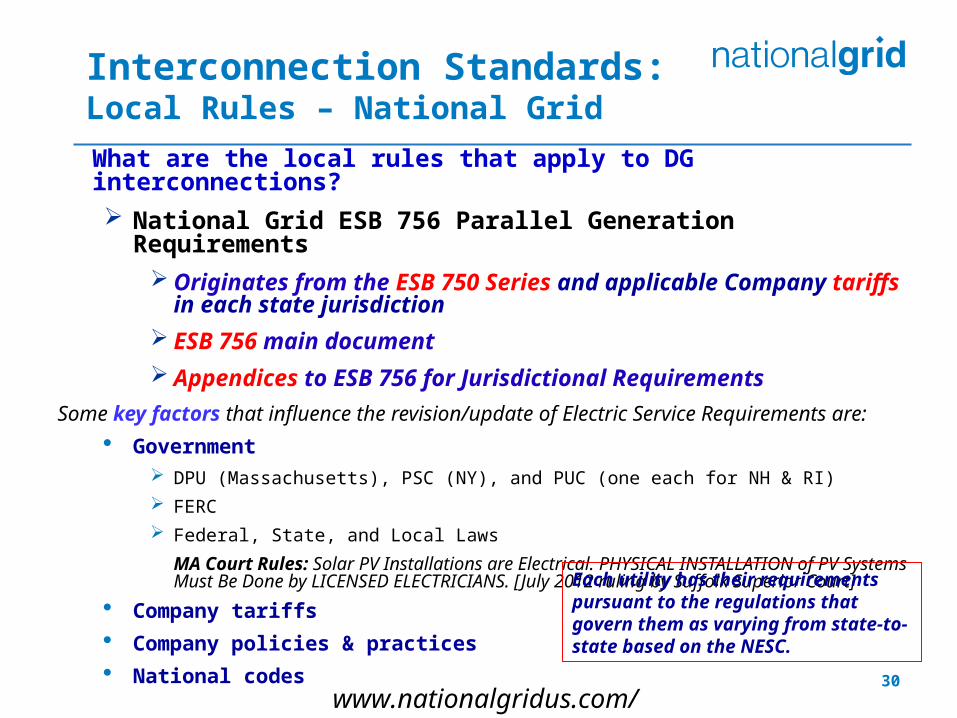
What are the local rules that apply to DG interconnections?
National Grid ESB 756 Parallel Generation Requirements Originates from the ESB 750 Series and applicable Company
tariffs in each state jurisdiction
ESB 756 main document
Appendices to ESB 756 for Jurisdictional Requirements
Some key factors that influence the revision/update of Electric Service Requirements are:
Government DPU (Massachusetts), PSC (NY), and PUC (one each for NH & RI)
FERC
Federal, State, and Local Laws
MA Court Rules: Solar PV Installations are Electrical. PHYSICAL INSTALLATION of PV Systems Must Be Done by LICENSED ELECTRICIANS. [July 2012 ruling by Suffolk Superior Court]
Company tariffs
Company policies & practices
National codes
Interconnection Standards:Local Rules – National Grid
www.nationalgridus.com/electricalspecifications
Each utility has their requirements pursuant to the regulations that govern them as varying from state-to-state based on the NESC.
30
Key Points for Electric Service Requirements:
Require some means of disconnect and main overcurrent protection, i.e., service equipment.
Billing meters secure.
Interface points clear to avoid potential operating and safety problems.
Interconnection Standards: (cont’d) National Grid ESB 750 Series
Key Points for Parallel Generation Requirements: Company determines the
interconnect voltage and method of interconnection.
Prior notification to and approval by the Company is required for any generation to be installed or operated in parallel with the Company EPS.
31
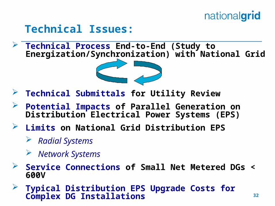
Technical Process End-to-End (Study to Energization/Synchronization) with National Grid
Technical Submittals for Utility Review
Potential Impacts of Parallel Generation on Distribution Electrical Power Systems (EPS)
Limits on National Grid Distribution EPS
Radial Systems
Network Systems
Service Connections of Small Net Metered DGs < 600V
Typical Distribution EPS Upgrade Costs for Complex DG Installations
Technical Issues:
32
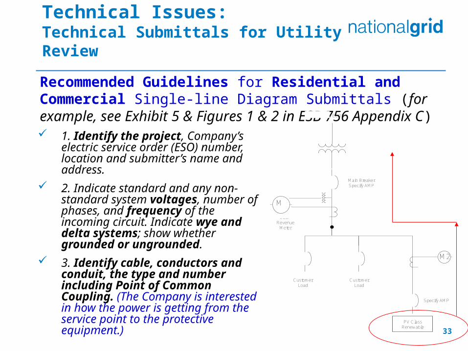
1. Identify the project, Company’s electric service order (ESO) number, location and submitter’s name and address.
2. Indicate standard and any non-standard system voltages, number of phases, and frequency of the incoming circuit. Indicate wye and delta systems; show whether grounded or ungrounded.
3. Identify cable, conductors and conduit, the type and number including Point of Common Coupling. (The Company is interested in how the power is getting from the service point to the protective equipment.)
Technical Issues:Technical Submittals for Utility Review
Recommended Guidelines for Residential and Commercial Single-line Diagram Submittals (for example, see Exhibit 5 & Figures 1 & 2 in ESB 756 Appendix C)
M
PV Class Renewable
M2
Customer Load
Customer Load
CL&P FEEDER
CL&P Revenue
Meter
Main BreakerSpecify AMP
Specify AMP
33
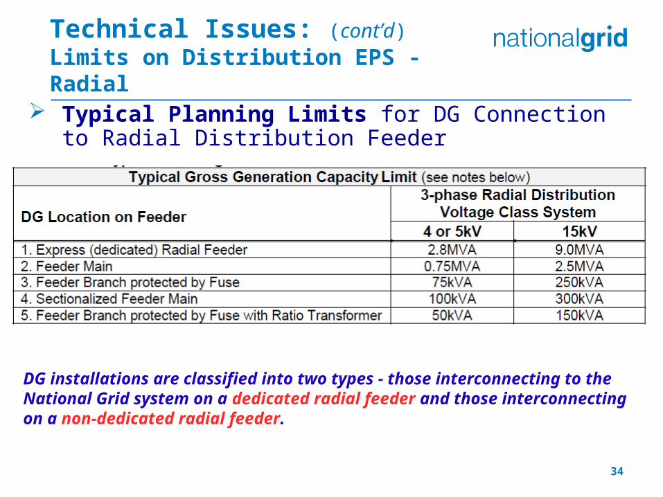
Typical Planning Limits for DG Connection to Radial Distribution Feeder
DG installations are classified into two types - those interconnecting to the National Grid system on a dedicated radial feeder and those interconnecting on a non-dedicated radial feeder.
Technical Issues: (cont’d)Limits on Distribution EPS - Radial
34

Anti-Islanding Protection
The Company’s position is that the interconnection of all parallel generators requires safeguards for synchronization and back-feed situations. A parallel generator is prohibited to energize a de-energized Company circuit.
The Company uses three main “tests”; any determine if anti-islanding protection is required for exceeding minimum load issue or a protection issue or operating concern:
1. “Feeder Load versus Generation Test”
2. “Fault Sensitivity Test”
3. “Feeder Selectivity Test”
Tips DG Customer’s protective device coordination study demonstrates generation
voltage and/or frequency protection will trip within 2.00 seconds for the loss of the utility source.
Type-tested inverter-based parallel generation operated in regulated current mode, transient overvoltage protection is required upon detection of an island.
When DTT is specified for a parallel generation project, the Company will determine the requirements and responsibilities for equipment, installation, and communications media in the interconnection study.
Technical Issues: Anti-Islanding on Distribution EPS - Radial
35
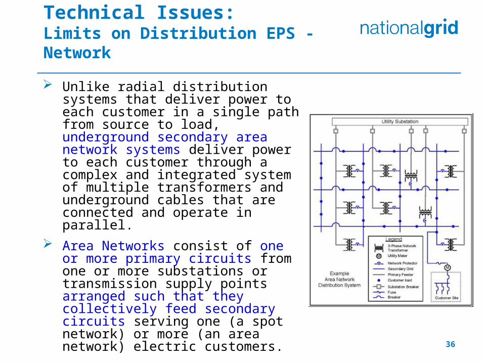
Unlike radial distribution systems that deliver power to each customer in a single path from source to load, underground secondary area network systems deliver power to each customer through a complex and integrated system of multiple transformers and underground cables that are connected and operate in parallel.
Area Networks consist of one or more primary circuits from one or more substations or transmission supply points arranged such that they collectively feed secondary circuits serving one (a spot network) or more (an area network) electric customers.
Technical Issues:Limits on Distribution EPS - Network
36
Technical Issues: (cont’d)Limits on Distribution EPS - Network
37
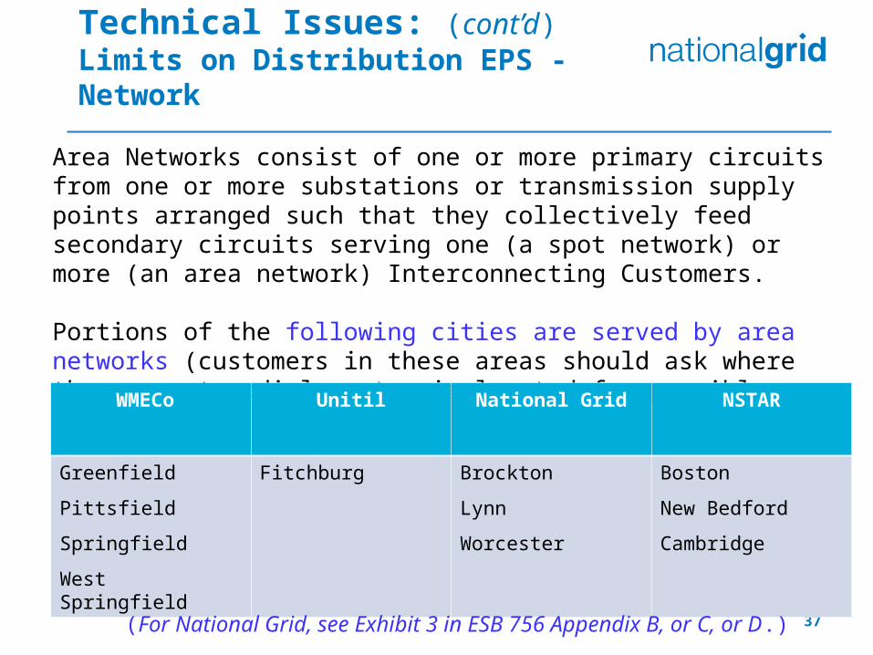
Area Networks consist of one or more primary circuits from one or more substations or transmission supply points arranged such that they collectively feed secondary circuits serving one (a spot network) or more (an area network) Interconnecting Customers.
Portions of the following cities are served by area networks (customers in these areas should ask where the nearest radial system is located for possible tie-in):
WMECo Unitil National Grid NSTAR
Greenfield
Pittsfield
Springfield
West Springfield
Fitchburg Brockton
Lynn
Worcester
Boston
New Bedford
Cambridge
(For National Grid, see Exhibit 3 in ESB 756 Appendix B, or C, or D.)
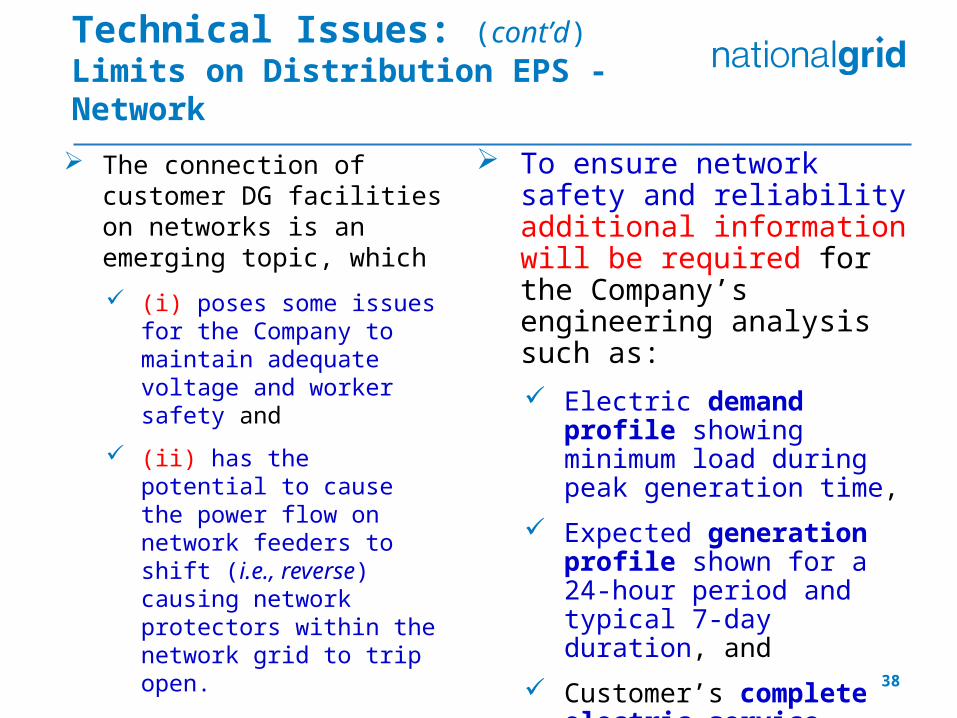
The connection of customer DG facilities on networks is an emerging topic, which
(i) poses some issues for the Company to maintain adequate voltage and worker safety and
(ii) has the potential to cause the power flow on network feeders to shift (i.e., reverse) causing network protectors within the network grid to trip open.
Technical Issues: (cont’d)Limits on Distribution EPS - Network
To ensure network safety and reliability additional information will be required for the Company’s engineering analysis such as:
Electric demand profile showing minimum load during peak generation time,
Expected generation profile shown for a 24-hour period and typical 7-day duration, and
Customer’s complete electric service single-line diagram up to the service point supplied by the Company’s secondary network EPS. 38
Technical Issues: Upgrades and System Modifications
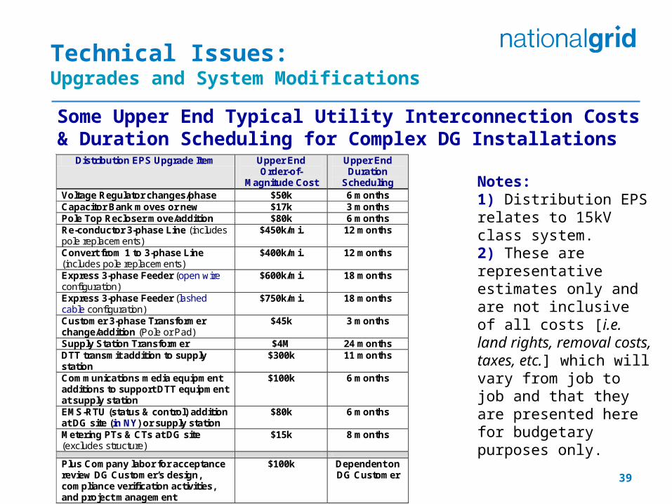
Some Upper End Typical Utility Interconnection Costs & Duration Scheduling for Complex DG Installations
Notes:1) Distribution EPS relates to 15kV class system. 2) These are representative estimates only and are not inclusive of all costs [i.e. land rights, removal costs, taxes, etc.] which will vary from job to job and that they are presented here for budgetary purposes only.
Distribution EPS Upgrade Item Upper End Order-of-
Magnitude Cost
Upper End Duration
Scheduling Voltage Regulator changes/phase $50k 6 months Capacitor Bank moves or new $17k 3 months Pole Top Recloser move/addition $80k 6 months Re-conductor 3-phase Line (includes pole replacements)
$450k/mi. 12 months
Convert from 1 to 3-phase Line (includes pole replacements)
$400k/mi. 12 months
Express 3-phase Feeder (open wire configuration)
$600k/mi. 18 months
Express 3-phase Feeder (lashed cable configuration)
$750k/mi. 18 months
Customer 3-phase Transformer change/addition (Pole or Pad)
$45k 3 months
Supply Station Transformer $4M 24 months DTT transmit addition to supply station
$300k 11 months
Communications media equipment additions to support DTT equipment at supply station
$100k 6 months
EMS-RTU (status & control) addition at DG site (in NY) or supply station
$80k 6 months
Metering PTs & CTs at DG site (excludes structure)
$15k 8 months
Plus Company labor for acceptance review DG Customer’s design, compliance verification activities, and project management
$100k Dependent on DG Customer
39
Post ISA CoordinationWitness Testing (overview)
1.) Relay Witness Testing
•National Grid Witnesses relays trip based on settings approved by NG Protection Engineer
2.) DTT Witness Testing
•Communication (RFL) to the Local Substation
•Typically Fiber or Lease line
3.) RTU Witness Testing (≥1MW)
•Provide Real time monitoring of Large DG at National Grid’s Regional Control Center.
•Ordering Correct (MPLS) communication circuit from Verizon
•Verizon Regional Account Teams consults with Verizon’s “Service Delivery” Department
40
41
AppendixNet Metering
42
Net Metering in Massachusetts
• December 2009 Net Metering Tariff• Three Net Metering Classes
– Class 1: Any generator up to 60 KW is eligible– Class 2: Agricultural, solar, or wind net metering
facility over 60 KW but less than or equal to 1 MW (for municipal or government it’s “per unit)
– Class 3: Agricultural, solar, or wind net metering facility over 1 MW but less than or equal to 2 MW (for municipal or government it’s “per unit”)
• Recent changes – limits projects to 2 MWs per parcel of land and a
single meter– Must apply to the System of Assurance (SofA) at
massaca.org for net metering services
43
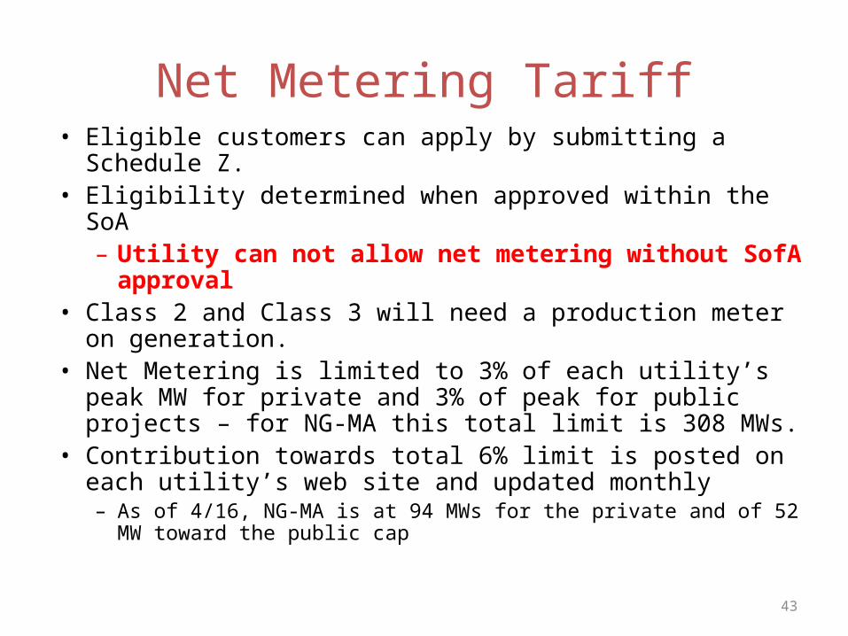
Net Metering Tariff• Eligible customers can apply by submitting a Schedule Z.• Eligibility determined when approved within the SoA
– Utility can not allow net metering without SofA approval• Class 2 and Class 3 will need a production meter on
generation.• Net Metering is limited to 3% of each utility’s peak MW for
private and 3% of peak for public projects – for NG-MA this total limit is 308 MWs.
• Contribution towards total 6% limit is posted on each utility’s web site and updated monthly– As of 4/16, NG-MA is at 94 MWs for the private and of 52 MW toward
the public cap

Net Metering changes
• Three Factor Approach (order 11-11C)– Single parcel / single interconnection point / single meter
• Enacted to limit gaming and limits one meter per parcel of land with a limit of 2 MWs on the parcel for private entities
– A governmental entity can have a total of 10 MWs of net-metered accounts throughout the state or on a parcel
– No more 6 – 1 MW projects on a parcel– We can not provide more than one interconnection point (POI)
• In addition, if there’s an existing meter(s) on a parcel, then customer can’t request a meter just for the net metering facility, it must be behind an existing meter
– Otherwise separate metered project could earn higher credits than if it was behind an existing meter
44
Net Metering and Interconnection Order
• Net Metering eligibility
– The DPU ruled in the interconnection tariff order (10-75E) that “Early ISA’s” will NOT meet the executed ISA requirement for entrance into the System of Assurance, and will refer the matter to DPU 11-11 for further investigation.
– Until such time as the DPU reaches a resolution of the issue, Distribution Companies are directed to clearly mark Early ISAs on the title page and on the signature page with the words “Early ISA” for identification purposes.

46
Net Metering Credits
Credit the following charges
Tier min max Type
Default Service
kWH
Dist- ribution
kWH
Trans- mission
kWH
Trans- ition kWH
1 0 60 KWAgriculture Wind, PV X X X X
2 >60 KW 1 MWAgriculture Wind, PV X X X X
3 >1 MW 2 MWAgriculture Wind, PV X Gov’t only X X
• Energy use is “netted” over the billing month– If there is net energy use – utility will bill customer for net use– If net energy export – export kWH * the following
• Renewable installations will be credited at near retail rate for excess kWH (minus conservation and renewable energy charges).
• Non-Renewable credited at average monthly clearing price ISO-NE• Tariff allows credits to be allocated (with limitations) • Customer still responsible for customer charges and demand
charges, even if net export
47
48
49
50
Net Metering Production Reporting
• Net Metering Tariff requires reporting of generator’s kWH output.
• Class 1 Facilities to provide in writing by January 31 and September 30
• Class 2 and Class 3 Facilities may participate in production tracking system (PTS).– Mass CEC provided PTS data to the utilities, still working
through implementation issues– Utility will request data from Class 2 and 3 Facilities

51
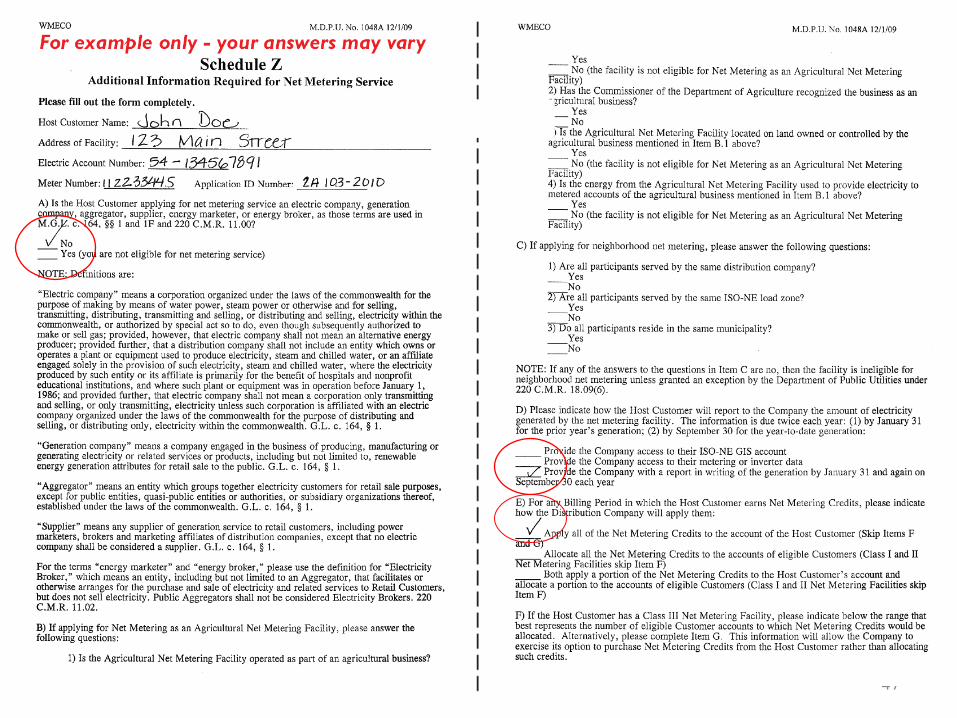
Net Metering Summary• If planning to Net Meter, submit Schedule Z with
interconnection application• Correctly fill out Schedule Z
– Name must match electric account of Host Customer
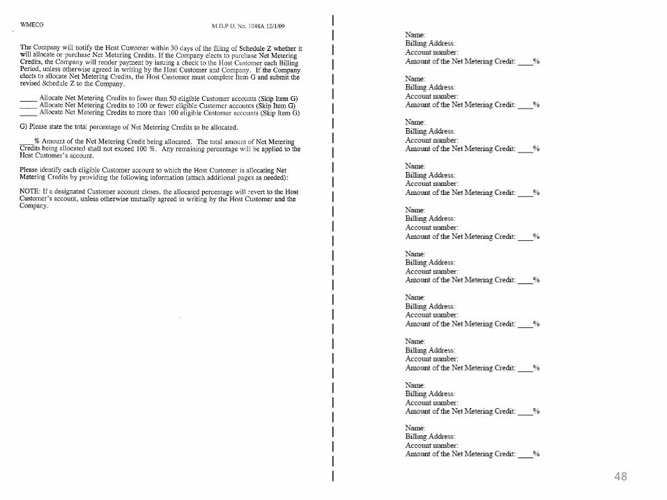
– Must be signed by Host Customer• If allocating, verify name/address/account info of
customer(s) – or will need to submit corrected form• Production reporting is required.• Over 60 kWs require registration as a settlement only
generator (SOG) associated ISO OP 18 metering requirements