Embed Size (px)
Citation preview
AbstractWith mounting pressure on Indian manufacturers to meet future fuel economy and emissions mandates-including the recently passed Corporate Average Fuel Consumption (CAFC) standards for light-duty vehicles-many are evaluating new technologies. However, to provide an economically sustainable solution, these technologies must increase efficiency without increasing cost.
One promising solution to meet both current, and future, standards is the opposed-piston engine. Widely used in the early 20th century for on-road applications, use of the opposed-piston engine waseventually discontinued due to challenges with emissions and oil control. But advancements in computer-aided engineering tools, combined with state-of-the-art engineering practices, has enabled Achates Power to develop a modern opposed-piston diesel engine architecture that is clean, significantly more fuel efficient and less expensive to manufacture than today's four-stroke engines.
In addition to a short explanation of the opposed-piston engine and its inherent efficiency benefits, this technical paper will provide detailed performance and emissions results of a multi-cylinder Achates Power opposed-piston engine configured to meet commercial truck requirements. These results, which will be presented for the first time in India, demonstrate the engine's ability to:
• Substantially improve fuel economy over the best diesels in the same class
• Comply with U.S. 2010/Euro 6 emissions standards
This paper also provides a detailed overview of the opposed-piston multi-cylinder test engine's indicated thermal efficiency, friction and pumping losses.
IntroductionThe government of India has recently announced new fuel economy standards for passenger vehicles which includes cars, vans and untility vehicles. These standards referred as ‘Corporate Average Fuel Consumption’ (CAFC) standards, will require these vehicles to be 14% more fuel efficient by 2016-2017 and 38% more efficient five years thereafter.
Also for the commercial vehicles with high utilization, the cost of ownership is of utmost importance for indian consumers.
For Indian consumers, keeping the cost of ownership down is an important factor. This is why, today most of these vehicles are powered by four-stroke diesel engines, which have been steadily enhanced for decades and improving them furthermore presents a daunting challenge.Additionally, new technologies being developed for four stoke engines, such as wasteheat recovery and hybridization, add significant cost, weight and complexity for comparatively smaller gain in fuel economy.
By contrast, the opposed-piston 2-stroke engine provides a more efficient platform at a similar or lower cost than a conventional four-stroke engine of equivalent technology level and performance.
Moreover, most of other engine technologies can also be applied to Achates Power opposed-piston 2-stroke engine design.
Opposed-Piston Engine Architectural AdvantagesOpposed-piston, two-stroke engines were conceived in the 1800s in Europe and subsequently developed in multiple countries for a wide variety of applications, including aircraft, ships, tanks, trucks and locomotives. They maintained their presence throughout the twentieth century. An excellent summary of the history of opposed-piston engines can be found in the SAE book, Opposed-Piston Engines: Evolution, Use, and Future Applications by M. Flint and J.P. Pirault
Opposed-Piston 2-Stroke Multi-Cylinder Engine Dynamometer Demonstration
2015-26-0038
Published 01/14/2015
Suramya Naik, Fabien Redon, Gerhard Regner, and John KoszewnikAchates Power Inc
CITATION: Naik, S., Redon, F., Regner, G., and Koszewnik, J., "Opposed-Piston 2-Stroke Multi-Cylinder Engine Dynamometer Demonstration," SAE Technical Paper 2015-26-0038, 2015, doi:10.4271/2015-26-0038.
Copyright © 2015 SAE International and Copyright © SAEINDIA
[2]. Produced initially for their manufacturability and high power density, opposed-piston, two-stroke engines have demonstrated superior fuel efficiency compared to their four-stroke counterparts. This section examines the underlying reasons for the superior fuel efficiency and emissions. The OP2S diesel engine has the following efficiency advantages compared to a conventional, four-stroke diesel engine:
1. Reduced Heat Losses
The increase in stroke-to-bore ratio has a direct mathematical relationship to the area-to-volume ratio of the combustion space. For example, when comparing a single-piston engine to an opposed-piston engine with the same piston slider dimensions, the following outcome can be seen:
Table 1. OP2S compared to a single-piston engine.
In this example, the reduction in the surface area top volume ratio is a very significant 36%. The lower surface area directly leads to a reduction in heat transfer.
2. Leaner Combustion
The amount of fuel injected for each combustion event is similar, but the cylinder volume is more than 50% greater for the Achates Power opposed-piston engine. So for the same boost conditions, the opposed-piston engine will achieve leaner combustion, which increases the ratio of specific heat. Increasing the ratio of specific heat increases the pressure rise during combustion and increases the work extraction per unit of volume expansion during the expansion stroke.
3. Faster and Earlier Combustion at the Same Pressure Rise Rate
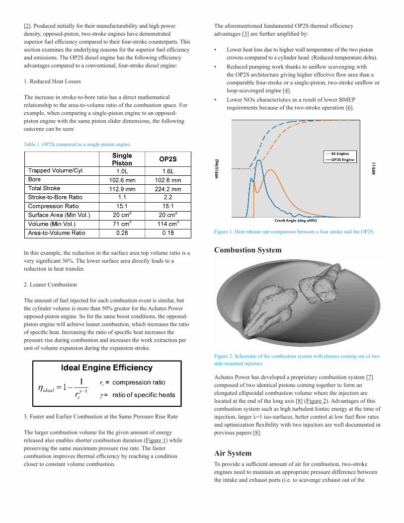
The larger combustion volume for the given amount of energy released also enables shorter combustion duration (Figure 1) while preserving the same maximum pressure rise rate. The faster combustion improves thermal efficiency by reaching a condition closer to constant volume combustion.
The aforementioned fundamental OP2S thermal efficiency advantages [3] are further amplified by:
• Lower heat loss due to higher wall temperature of the two piston crowns compared to a cylinder head. (Reduced temperature delta).
• Reduced pumping work thanks to uniflow scavenging with the OP2S architecture giving higher effective flow area than a comparable four-stroke or a single-piston, two-stroke uniflow or loop-scavenged engine [4].
• Lower NOx characteristics as a result of lower BMEP requirements because of the two-stroke operation [6].
Figure 1. Heat release rate comparison between a four stroke and the OP2S.
Combustion System
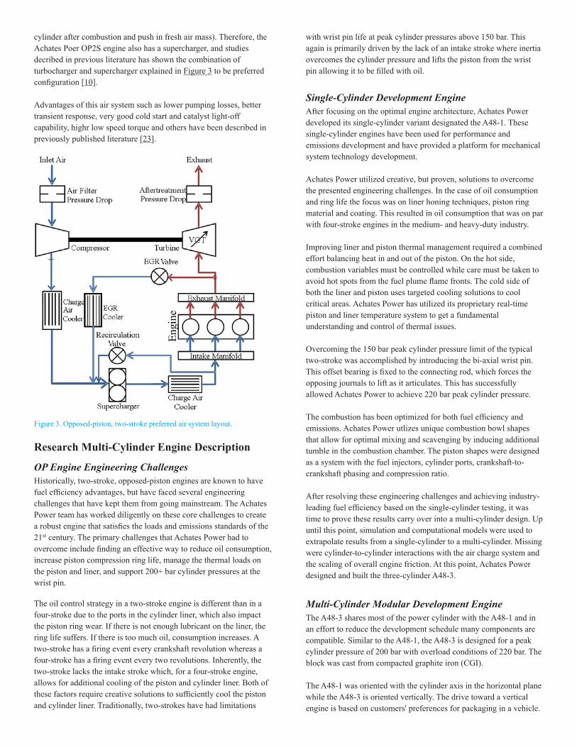
Figure 2. Schematic of the combustion system with plumes coming out of two side-mounted injectors.
Achates Power has developed a proprietary combustion system [7] composed of two identical pistons coming together to form an elongated ellipsoidal combustion volume where the injectors are located at the end of the long axis [8] (Figure 2). Advantages of this combustion system such as high turbulent kintec energy at the time of injection, larger λ=1 iso-surfaces, better control at low fuel flow rates and optimization flexibility with two injectors are well documented in previous papers [8].
Air SystemTo provide a sufficient amount of air for combustion, two-stroke engines need to maintain an appropriate pressure difference between the intake and exhaust ports (i.e. to scavenge exhaust out of the
cylinder after combustion and push in fresh air mass). Therefore, the Achates Poer OP2S engine also has a supercharger, and studies decribed in previous literature has shown the combination of turbocharger and supercharger explained in Figure 3 to be preferred configuration [10].
Advantages of this air system such as lower pumping losses, better transient response, very good cold start and catalyst light-off capability, highr low speed torque and others have been described in previously published literature [23].
Figure 3. Opposed-piston, two-stroke preferred air system layout.
Research Multi-Cylinder Engine Description
OP Engine Engineering ChallengesHistorically, two-stroke, opposed-piston engines are known to have fuel efficiency advantages, but have faced several engineering challenges that have kept them from going mainstream. The Achates Power team has worked diligently on these core challenges to create a robust engine that satisfies the loads and emissions standards of the 21st century. The primary challenges that Achates Power had to overcome include finding an effective way to reduce oil consumption, increase piston compression ring life, manage the thermal loads on the piston and liner, and support 200+ bar cylinder pressures at the wrist pin.
The oil control strategy in a two-stroke engine is different than in a four-stroke due to the ports in the cylinder liner, which also impact the piston ring wear. If there is not enough lubricant on the liner, the ring life suffers. If there is too much oil, consumption increases. A two-stroke has a firing event every crankshaft revolution whereas a four-stroke has a firing event every two revolutions. Inherently, the two-stroke lacks the intake stroke which, for a four-stroke engine, allows for additional cooling of the piston and cylinder liner. Both of these factors require creative solutions to sufficiently cool the piston and cylinder liner. Traditionally, two-strokes have had limitations
with wrist pin life at peak cylinder pressures above 150 bar. This again is primarily driven by the lack of an intake stroke where inertia overcomes the cylinder pressure and lifts the piston from the wrist pin allowing it to be filled with oil.
Single-Cylinder Development EngineAfter focusing on the optimal engine architecture, Achates Power developed its single-cylinder variant designated the A48-1. These single-cylinder engines have been used for performance and emissions development and have provided a platform for mechanical system technology development.
Achates Power utilized creative, but proven, solutions to overcome the presented engineering challenges. In the case of oil consumption and ring life the focus was on liner honing techniques, piston ring material and coating. This resulted in oil consumption that was on par with four-stroke engines in the medium- and heavy-duty industry.
Improving liner and piston thermal management required a combined effort balancing heat in and out of the piston. On the hot side, combustion variables must be controlled while care must be taken to avoid hot spots from the fuel plume flame fronts. The cold side of both the liner and piston uses targeted cooling solutions to cool critical areas. Achates Power has utilized its proprietary real-time piston and liner temperature system to get a fundamental understanding and control of thermal issues.
Overcoming the 150 bar peak cylinder pressure limit of the typical two-stroke was accomplished by introducing the bi-axial wrist pin. This offset bearing is fixed to the connecting rod, which forces the opposing journals to lift as it articulates. This has successfully allowed Achates Power to achieve 220 bar peak cylinder pressure.
The combustion has been optimized for both fuel efficiency and emissions. Achates Power utlizes unique combustion bowl shapes that allow for optimal mixing and scavenging by inducing additional tumble in the combustion chamber. The piston shapes were designed as a system with the fuel injectors, cylinder ports, crankshaft-to-crankshaft phasing and compression ratio.
After resolving these engineering challenges and achieving industry-leading fuel efficiency based on the single-cylinder testing, it was time to prove these results carry over into a multi-cylinder design. Up until this point, simulation and computational models were used to extrapolate results from a single-cylinder to a multi-cylinder. Missing were cylinder-to-cylinder interactions with the air charge system and the scaling of overall engine friction. At this point, Achates Power designed and built the three-cylinder A48-3.
Multi-Cylinder Modular Development EngineThe A48-3 shares most of the power cylinder with the A48-1 and in an effort to reduce the development schedule many components are compatible. Similar to the A48-1, the A48-3 is designed for a peak cylinder pressure of 200 bar with overload conditions of 220 bar. The block was cast from compacted graphite iron (CGI).
The A48-1 was oriented with the cylinder axis in the horizontal plane while the A48-3 is oriented vertically. The drive toward a vertical engine is based on customers' preferences for packaging in a vehicle.
There are several challenges with the vertical or slightly slanted orientation that needed to be overcome. Examples include the potential filling of the upper (intake) piston with oil upon shutdown and the upper crankcase oil drainage.
The A48-1 and A48-3 engines were created as a research test bed to quickly iterate through multiple different designs. In creating such a platform, some compromises were made versus how a production engine would be conceived. Some examples of the experimental aspects include:
• Higher overall engine mass - robustness and quick turn around • Larger package size - modular/swappable components • Higher friction
▪Off-the-shelf connecting rod big end and main bearings ▪Aftermarket oil and coolant pumps
• Modular gearbox connecting the exhaust and intake crank • Modular FEAD • Modular accessories
Friction can be trimmed in several areas. Due to available bearing sizes and the need for a robust development platform, the loading calculations for both the connecting rod big end and main bearings resulted in oversized components. More of the cooling in the opposed-piston engine is done with the oil so the efficiency of the oil pump is important and can be improved with deeper supplier involvement.
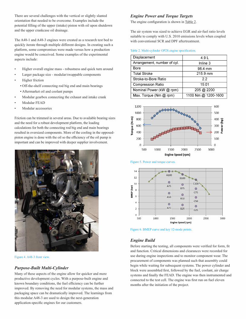
Figure 4. A48-3 front view.
Purpose-Built Multi-CylinderMany of these aspects of the engine allow for quicker and more productive development cycles. With a purpose-built engine and known boundary conditions, the fuel efficiency can be further improved. By removing the need for modular systems, the mass and packaging space can be dramatically improved. The learnings from this modular A48-3 are used to design the next-generation application-specific engines for our customers.
Engine Power and Torque TargetsThe engine configuration is shown in Table 2.
The air system was sized to achieve EGR and air-fuel ratio levels suitable to comply with U.S. 2010 emissions levels when coupled with conventional SCR and DPF aftertreatment.
Table 2. Multi-cylinder OP2S engine specification.
Figure 5. Power and torque curves.
Figure 6. BMEP curve and key 12-mode points.
Engine BuildBefore starting the testing, all components were verified for form, fit and function. Critical dimensions and clearances were recorded for use during engine inspections and to monitor component wear. The procurement of components was planned such that assembly could begin while waiting for subsequent systems. The power cylinder and block were assembled first, followed by the fuel, coolant, air charge systems and finally the FEAD. The engine was then instrumented and connected to the test cell. The engine was first run on fuel eleven months after the initiation of the project.
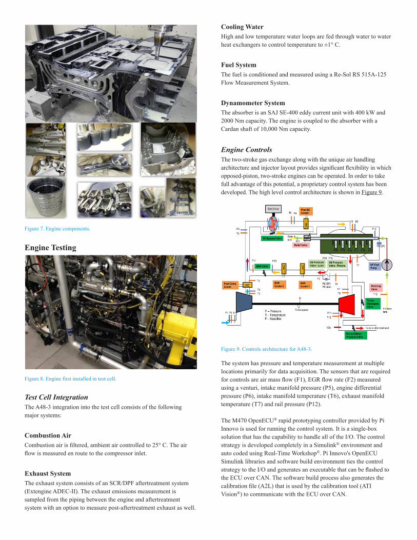
Figure 7. Engine components.
Engine Testing
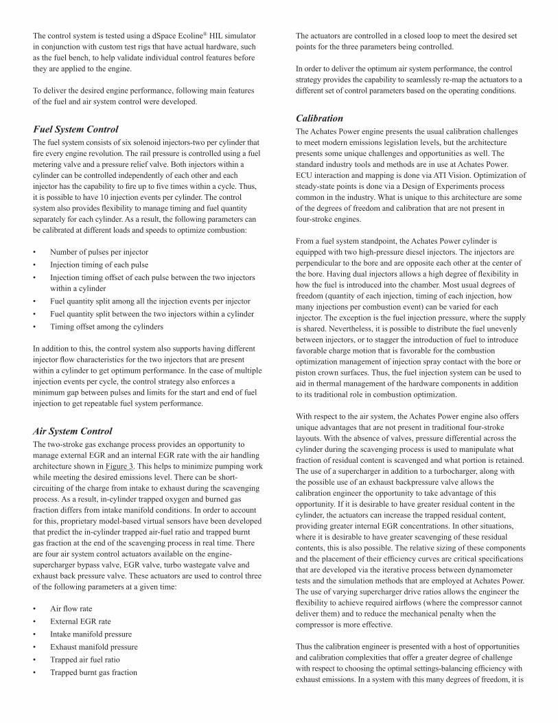
Figure 8. Engine first installed in test cell.
Test Cell IntegrationThe A48-3 integration into the test cell consists of the following major systems:
Combustion AirCombustion air is filtered, ambient air controlled to 25° C. The air flow is measured en route to the compressor inlet.
Exhaust SystemThe exhaust system consists of an SCR/DPF aftertreatment system (Extengine ADEC-II). The exhaust emissions measurement is sampled from the piping between the engine and aftertreatment system with an option to measure post-aftertreatment exhaust as well.
Cooling WaterHigh and low temperature water loops are fed through water to water heat exchangers to control temperature to ±1° C.
Fuel SystemThe fuel is conditioned and measured using a Re-Sol RS 515A-125 Flow Measurement System.
Dynamometer SystemThe absorber is an SAJ SE-400 eddy current unit with 400 kW and 2000 Nm capacity. The engine is coupled to the absorber with a Cardan shaft of 10,000 Nm capacity.
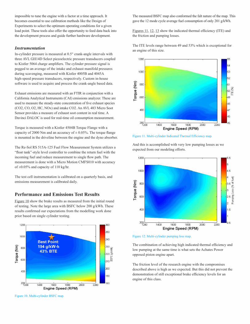
Engine ControlsThe two-stroke gas exchange along with the unique air handling architecture and injector layout provides significant flexibility in which opposed-piston, two-stroke engines can be operated. In order to take full advantage of this potential, a proprietary control system has been developed. The high level control architecture is shown in Figure 9.
Figure 9. Controls architecture for A48-3.
The system has pressure and temperature measurement at multiple locations primarily for data acquisition. The sensors that are required for controls are air mass flow (F1), EGR flow rate (F2) measured using a venturi, intake manifold pressure (P5), engine differential pressure (P6), intake manifold temperature (T6), exhaust manifold temperature (T7) and rail pressure (P12).
The M470 OpenECU® rapid prototyping controller provided by Pi Innovo is used for running the control system. It is a single-box solution that has the capability to handle all of the I/O. The control strategy is developed completely in a Simulink® environment and auto coded using Real-Time Workshop®. Pi Innovo's OpenECU Simulink libraries and software build environment ties the control strategy to the I/O and generates an executable that can be flashed to the ECU over CAN. The software build process also generates the calibration file (A2L) that is used by the calibration tool (ATI Vision®) to communicate with the ECU over CAN.
The control system is tested using a dSpace Ecoline® HIL simulator in conjunction with custom test rigs that have actual hardware, such as the fuel bench, to help validate individual control features before they are applied to the engine.
To deliver the desired engine performance, following main features of the fuel and air system control were developed.
Fuel System ControlThe fuel system consists of six solenoid injectors-two per cylinder that fire every engine revolution. The rail pressure is controlled using a fuel metering valve and a pressure relief valve. Both injectors within a cylinder can be controlled independently of each other and each injector has the capability to fire up to five times within a cycle. Thus, it is possible to have 10 injection events per cylinder. The control system also provides flexibility to manage timing and fuel quantity separately for each cylinder. As a result, the following parameters can be calibrated at different loads and speeds to optimize combustion:
• Number of pulses per injector • Injection timing of each pulse • Injection timing offset of each pulse between the two injectors
within a cylinder • Fuel quantity split among all the injection events per injector • Fuel quantity split between the two injectors within a cylinder • Timing offset among the cylinders
In addition to this, the control system also supports having different injector flow characteristics for the two injectors that are present within a cylinder to get optimum performance. In the case of multiple injection events per cycle, the control strategy also enforces a minimum gap between pulses and limits for the start and end of fuel injection to get repeatable fuel system performance.
Air System ControlThe two-stroke gas exchange process provides an opportunity to manage external EGR and an internal EGR rate with the air handling architecture shown in Figure 3. This helps to minimize pumping work while meeting the desired emissions level. There can be short-circuiting of the charge from intake to exhaust during the scavenging process. As a result, in-cylinder trapped oxygen and burned gas fraction differs from intake manifold conditions. In order to account for this, proprietary model-based virtual sensors have been developed that predict the in-cylinder trapped air-fuel ratio and trapped burnt gas fraction at the end of the scavenging process in real time. There are four air system control actuators available on the engine-supercharger bypass valve, EGR valve, turbo wastegate valve and exhaust back pressure valve. These actuators are used to control three of the following parameters at a given time:
• Air flow rate • External EGR rate • Intake manifold pressure • Exhaust manifold pressure • Trapped air fuel ratio • Trapped burnt gas fraction
The actuators are controlled in a closed loop to meet the desired set points for the three parameters being controlled.
In order to deliver the optimum air system performance, the control strategy provides the capability to seamlessly re-map the actuators to a different set of control parameters based on the operating conditions.
CalibrationThe Achates Power engine presents the usual calibration challenges to meet modern emissions legislation levels, but the architecture presents some unique challenges and opportunities as well. The standard industry tools and methods are in use at Achates Power. ECU interaction and mapping is done via ATI Vision. Optimization of steady-state points is done via a Design of Experiments process common in the industry. What is unique to this architecture are some of the degrees of freedom and calibration that are not present in four-stroke engines.
From a fuel system standpoint, the Achates Power cylinder is equipped with two high-pressure diesel injectors. The injectors are perpendicular to the bore and are opposite each other at the center of the bore. Having dual injectors allows a high degree of flexibility in how the fuel is introduced into the chamber. Most usual degrees of freedom (quantity of each injection, timing of each injection, how many injections per combustion event) can be varied for each injector. The exception is the fuel injection pressure, where the supply is shared. Nevertheless, it is possible to distribute the fuel unevenly between injectors, or to stagger the introduction of fuel to introduce favorable charge motion that is favorable for the combustion optimization management of injection spray contact with the bore or piston crown surfaces. Thus, the fuel injection system can be used to aid in thermal management of the hardware components in addition to its traditional role in combustion optimization.
With respect to the air system, the Achates Power engine also offers unique advantages that are not present in traditional four-stroke layouts. With the absence of valves, pressure differential across the cylinder during the scavenging process is used to manipulate what fraction of residual content is scavenged and what portion is retained. The use of a supercharger in addition to a turbocharger, along with the possible use of an exhaust backpressure valve allows the calibration engineer the opportunity to take advantage of this opportunity. If it is desirable to have greater residual content in the cylinder, the actuators can increase the trapped residual content, providing greater internal EGR concentrations. In other situations, where it is desirable to have greater scavenging of these residual contents, this is also possible. The relative sizing of these components and the placement of their efficiency curves are critical specifications that are developed via the iterative process between dynamometer tests and the simulation methods that are employed at Achates Power. The use of varying supercharger drive ratios allows the engineer the flexibility to achieve required airflows (where the compressor cannot deliver them) and to reduce the mechanical penalty when the compressor is more effective.
Thus the calibration engineer is presented with a host of opportunities and calibration complexities that offer a greater degree of challenge with respect to choosing the optimal settings-balancing efficiency with exhaust emissions. In a system with this many degrees of freedom, it is
impossible to tune the engine with a factor at a time approach. It becomes essential to use calibration methods like the Design of Experiments to select the optimum operating conditions for a given load point. These tools also offer the opportunity to feed data back into the development process and guide further hardware development.
InstrumentationIn-cylinder pressure is measured at 0.5° crank-angle intervals with three AVL GH14D Select piezoelectric pressure transducers coupled to Kistler 5064 charge amplifiers. The cylinder pressure signal is pegged to an average of the intake and exhaust manifold pressures during scavenging, measured with Kistler 4005B and 4045A high-speed pressure transducers, respectively. Custom in-house software is used to acquire and process the crank-angle based data.
Exhaust emissions are measured with an FTIR in conjunction with a California Analytical Instruments (CAI) emissions analyzer. These are used to measure the steady-state concentration of five exhaust species (CO2, CO, O2, HC, NOx) and intake CO2. An AVL 483 Micro Soot Sensor provides a measure of exhaust soot content in real time. A Davinci DALOC is used for real-time oil consumption measurement.
Torque is measured with a Kistler 4504B Torque Flange with a capacity of 2000 Nm and an accuracy of ± 0.05%. The torque flange is mounted in the driveline between the engine and the dyno absorber.
The Re-Sol RS 515A-125 Fuel Flow Measurement System utilizes a “float tank”-style level controller to combine the return fuel with the incoming fuel and reduce measurement to single flow path. The measurement is done with a Micro Motion CMFS010 with accuracy of ±0.05% and capacity of 110 kg/hr.
The test cell instrumentation is calibrated on a quarterly basis, and emissions measurement is calibrated daily.
Performance and Emissions Test ResultsFigure 10 show the brake results as measured from the initial round of testing. Note the large area with BSFC below 200 g/kWh. These results confirmed our expectations from the modelling work done prior based on single cylinder testing.
Figure 10. Multi-cylinder BSFC map.
The measured BSFC map also conformed the falt nature of the map. This gave the 12 mode cycle average fuel consumption of only 201 g/kWh.
Figures 11, 12, 13 show the indicated thermal efficiency (ITE) and the friction and pumping losses.
The ITE levels range between 49 and 53% which is exceptional for an engine of this size.
Figure 11. Multi-cylinder Indicated Thermal Efficiency map.
And this is accomplished with very low pumping losses as we expected from our modeling efforts.
Figure 12. Multi-cylinder pumping loss map.
The combination of achieving high indicated thermal efficiency and low pumping at the same time is what sets the Achates Power opposed piston engine apart.
The friction level of the research engine with the compromises described above is high as we expected. But this did not prevent the demonstration of still exceptional brake efficiency levels for an engine of this class.
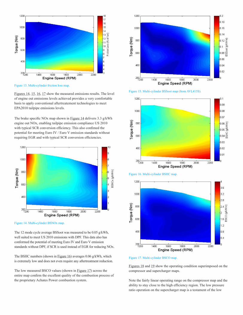
Figure 13. Multi-cylinder friction loss map.
Figures 14, 15, 16, 17 show the measured emissions results. The level of engine out emissions levels achieved provides a very comfortable basis to apply conventional aftertreatement technologies to meet EPA2010 tailpipe emissions levels.
The brake specific NOx map shown in Figure 14 delivers 3.3 g/kWh engine out NOx, enabling tailpipe emission compliance US 2010 with typical SCR conversion efficiency. This also confimed the potential for meeting Euro IV / Euro V emission standards without requiring EGR and with typical SCR conversion efficiencies.
Figure 14. Multi-cylinder BSNOx map.
The 12 mode cycle average BSSoot was measured to be 0.05 g/kWh, well suited to meet US 2010 emissions with DPF. This data also has conformed the potential of meeting Euro IV and Euro V emission standards without DPF, if SCR is used instead of EGR for reducing NOx.
The BSHC numbers (shown in Figure 16) averages 0.06 g/kWh, which is extremely low and does not even require any aftertreatment reduction.
The low measured BSCO values (shown in Figure 17) across the entire map confirm the excellent quality of the combustion process of the proprietary Achates Power combustion system.
Figure 15. Multi-cylinder BSSoot map (from AVL415S).
Figure 16. Multi-cylinder BSHC map.
Figure 17. Multi-cylinder BSCO map.
Figures 18 and 19 show the operating condition superimposed on the compressor and supercharger maps.
Note the fairly linear operating range on the compressor map and the ability to stay close to the high efficiency region. The low pressure ratio operation on the supercharger map is a testament of the low
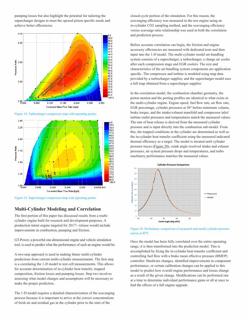
pumping losses but also highlight the potential for tailoring the supercharger designs to meet the oposed piston specific needs and achieve better efficiencies.
Figure 18. Turbocharger compressor map with operating points.
Figure 19. Supercharger compressor map with operating points.
Multi-Cylinder Modeling and CorrelationThe first portion of this paper has discussed results from a multi-cylinder engine built for research and development purposes. A production intent engine targeted for 2017+ release would include improvements in combustion, pumping and friction.
GT-Power, a powerful one-dimensional engine and vehicle simulation tool, is used to predict what the performance of such an engine would be.
A two-step approach is used in making future multi-cylinder predictions from current multi-cylinder measurements. The first step is a correlating the 1-D model to test cell measurements. This allows for accurate determination of in-cylinder heat transfer, trapped composition, friction losses and pumping losses. Step two involves assessing what model changes and assumptions will be necessary to make the proper prediction.
The 1-D model requires a detailed characterization of the scavenging process because it is important to arrive at the correct concentrations of fresh air and residual gas in the cylinder prior to the start of the
closed-cycle portion of the simulation. For this reason, the scavenging efficiency was measured in the test engine using an in-cylinder CO2 sampling method, and the scavenging efficiency versus scavenge ratio relationship was used in both the correlation and prediction process.
Before accurate correlation can begin, the friction and engine accessory efficiencies are measured with dedicated tests and then input into the 1-D model. The multi-cylinder model air-handling system consists of a supercharger, a turbocharger, a charge air cooler after each compression stage and EGR coolers. The size and characteristics of the air-handling system components are application specific. The compressor and turbine is modeled using map data provided by a turbocharger supplier, and the supercharger model uses a full map obtained from a supercharger supplier.
In the correlation model, the combustion chamber geometry, the piston motion and the porting profiles are identical to what exists in the multi-cylinder engine. Engine speed, fuel flow rate, air flow rate, EGR percentage, cylinder pressures at 30° before minimum volume, brake torque, and the intake/exhaust manifold and compressor inlet/turbine outlet pressures and temperatures match the measured values. The rate of heat release is derived from the measured cylinder pressure and is input directly into the combustion sub-model. From this, the trapped conditions in the cylinder are determined as well as the in-cylinder heat transfer coefficient using the measured indicated thermal efficiency as a target. The model is iterated until cylinder pressure traces (Figure 20), crank angle resolved intake and exhaust pressures, air system pressure drops and temperatures, and turbo machinery performance matches the measured values.
Figure 20. Preliminary comparison of measured and model cylinder pressure curves at B75.
Once the model has been fully correlated over the entire operating range, it is then transformed into the prediction model. This is accomplished by fixing the in-cylinder heat transfer coefficient and controlling fuel flow with a brake mean effective pressure (BMEP) controller. Hardware changes, identified improvements in component performance, or certain calibration changes can be applied to this model to predict how overall engine performance and losses change as a result of the given change. Modifications can be performed one at a time to determine individual performance gains or all at once to find the effects of a full engine upgrade.
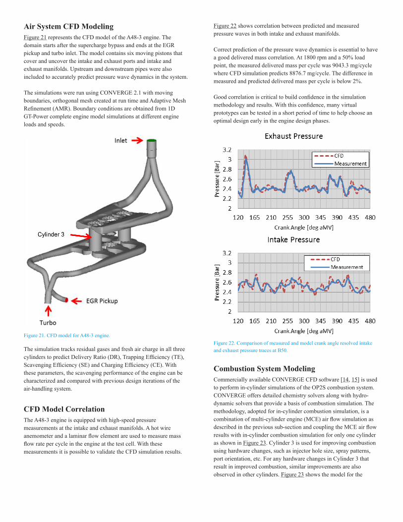
Air System CFD ModelingFigure 21 represents the CFD model of the A48-3 engine. The domain starts after the supercharge bypass and ends at the EGR pickup and turbo inlet. The model contains six moving pistons that cover and uncover the intake and exhaust ports and intake and exhaust manifolds. Upstream and downstream pipes were also included to accurately predict pressure wave dynamics in the system.
The simulations were run using CONVERGE 2.1 with moving boundaries, orthogonal mesh created at run time and Adaptive Mesh Refinement (AMR). Boundary conditions are obtained from 1D GT-Power complete engine model simulations at different engine loads and speeds.
Figure 21. CFD model for A48-3 engine.
The simulation tracks residual gases and fresh air charge in all three cylinders to predict Delivery Ratio (DR), Trapping Efficiency (TE), Scavenging Efficiency (SE) and Charging Efficiency (CE). With these parameters, the scavenging performance of the engine can be characterized and compared with previous design iterations of the air-handling system.
CFD Model CorrelationThe A48-3 engine is equipped with high-speed pressure measurements at the intake and exhaust manifolds. A hot wire anemometer and a laminar flow element are used to measure mass flow rate per cycle in the engine at the test cell. With these measurements it is possible to validate the CFD simulation results.
Figure 22 shows correlation between predicted and measured pressure waves in both intake and exhaust manifolds.
Correct prediction of the pressure wave dynamics is essential to have a good delivered mass correlation. At 1800 rpm and a 50% load point, the measured delivered mass per cycle was 9043.3 mg/cycle where CFD simulation predicts 8876.7 mg/cycle. The difference in measured and predicted delivered mass per cycle is below 2%.
Good correlation is critical to build confidence in the simulation methodology and results. With this confidence, many virtual prototypes can be tested in a short period of time to help choose an optimal design early in the engine design phases.
Figure 22. Comparison of measured and model crank angle resolved intake and exhaust pressure traces at B50.
Combustion System ModelingCommercially available CONVERGE CFD software [14, 15] is used to perform in-cylinder simulations of the OP2S combustion system. CONVERGE offers detailed chemistry solvers along with hydro-dynamic solvers that provide a basis of combustion simulation. The methodology, adopted for in-cylinder combustion simulation, is a combination of multi-cylinder engine (MCE) air flow simulation as described in the previous sub-section and coupling the MCE air flow results with in-cylinder combustion simulation for only one cylinder as shown in Figure 23. Cylinder 3 is used for improving combustion using hardware changes, such as injector hole size, spray patterns, port orientation, etc. For any hardware changes in Cylinder 3 that result in improved combustion, similar improvements are also observed in other cylinders. Figure 23 shows the model for the
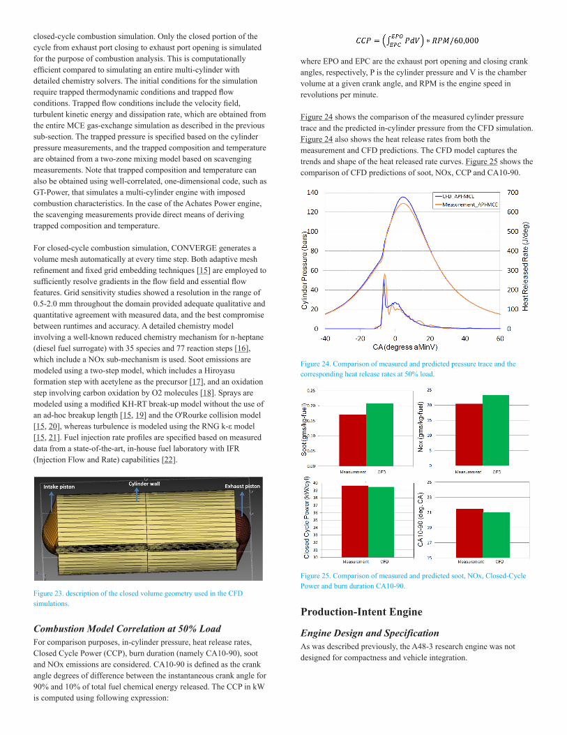
closed-cycle combustion simulation. Only the closed portion of the cycle from exhaust port closing to exhaust port opening is simulated for the purpose of combustion analysis. This is computationally efficient compared to simulating an entire multi-cylinder with detailed chemistry solvers. The initial conditions for the simulation require trapped thermodynamic conditions and trapped flow conditions. Trapped flow conditions include the velocity field, turbulent kinetic energy and dissipation rate, which are obtained from the entire MCE gas-exchange simulation as described in the previous sub-section. The trapped pressure is specified based on the cylinder pressure measurements, and the trapped composition and temperature are obtained from a two-zone mixing model based on scavenging measurements. Note that trapped composition and temperature can also be obtained using well-correlated, one-dimensional code, such as GT-Power, that simulates a multi-cylinder engine with imposed combustion characteristics. In the case of the Achates Power engine, the scavenging measurements provide direct means of deriving trapped composition and temperature.
For closed-cycle combustion simulation, CONVERGE generates a volume mesh automatically at every time step. Both adaptive mesh refinement and fixed grid embedding techniques [15] are employed to sufficiently resolve gradients in the flow field and essential flow features. Grid sensitivity studies showed a resolution in the range of 0.5-2.0 mm throughout the domain provided adequate qualitative and quantitative agreement with measured data, and the best compromise between runtimes and accuracy. A detailed chemistry model involving a well-known reduced chemistry mechanism for n-heptane (diesel fuel surrogate) with 35 species and 77 reaction steps [16], which include a NOx sub-mechanism is used. Soot emissions are modeled using a two-step model, which includes a Hiroyasu formation step with acetylene as the precursor [17], and an oxidation step involving carbon oxidation by O2 molecules [18]. Sprays are modeled using a modified KH-RT break-up model without the use of an ad-hoc breakup length [15, 19] and the O'Rourke collision model [15, 20], whereas turbulence is modeled using the RNG k-ε model [15, 21]. Fuel injection rate profiles are specified based on measured data from a state-of-the-art, in-house fuel laboratory with IFR (Injection Flow and Rate) capabilities [22].
Figure 23. description of the closed volume geometry used in the CFD simulations.
Combustion Model Correlation at 50% LoadFor comparison purposes, in-cylinder pressure, heat release rates, Closed Cycle Power (CCP), burn duration (namely CA10-90), soot and NOx emissions are considered. CA10-90 is defined as the crank angle degrees of difference between the instantaneous crank angle for 90% and 10% of total fuel chemical energy released. The CCP in kW is computed using following expression:
where EPO and EPC are the exhaust port opening and closing crank angles, respectively, P is the cylinder pressure and V is the chamber volume at a given crank angle, and RPM is the engine speed in revolutions per minute.
Figure 24 shows the comparison of the measured cylinder pressure trace and the predicted in-cylinder pressure from the CFD simulation. Figure 24 also shows the heat release rates from both the measurement and CFD predictions. The CFD model captures the trends and shape of the heat released rate curves. Figure 25 shows the comparison of CFD predictions of soot, NOx, CCP and CA10-90.
Figure 24. Comparison of measured and predicted pressure trace and the corresponding heat release rates at 50% load.
Figure 25. Comparison of measured and predicted soot, NOx, Closed-Cycle Power and burn duration CA10-90.
Production-Intent Engine
Engine Design and SpecificationAs was described previously, the A48-3 research engine was not designed for compactness and vehicle integration.
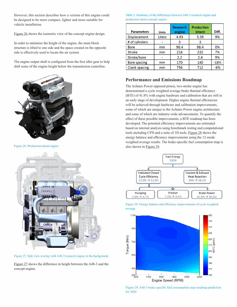
However, this section describes how a version of this engine could be designed to be more compact, lighter and more suitable for vehicle installation.
Figure 26 shows the isometric view of the concept engine design.
In order to minimize the height of the engine, the main block structure is tilted to one side and the space created on the opposite side is effectively used to locate the air system.
The engine output shaft is configured from the first idler gear to help shift some of the engine height below the transmission centerline.
Figure 26. Production-intent engine.
Figure 27. Side view overlay with A48-3 research engine in the background.
Figure 27 shows the difference in height between the A48-3 and the concept engine.
Table 3. Summary of the differences between A48-3 research engine and production intent concept engine.
Performance and Emissions RoadmapThe Achates Power opposed-piston, two-stroke engine has demonstrated a cycle weighted average brake thermal efficiency (BTE) of 41.8% with engine hardware and calibration that are still in an early stage of development. Higher engine thermal efficiencies will be achieved through hardware and calibration improvements, some of which are unique to the Achates Power engine architecture and some of which are industry-wide advancements. To quantify the effect of these possible improvements, a BTE roadmap has been developed. The potential efficiency improvements are estimated based on internal analysis using benchmark testing and computational tools including CFD and a suite of 1D tools. Figure 28 shows the energy balance and efficiency improvements using the 12-mode weighted average results. The brake-specific fuel consumption map is also shown in Figure 29.
Figure 28. Energy balance and efficiency improvements of cycle-weighted average.
Figure 29. A48-3 brake-specific fuel consumption map roadmap prediction for 2020
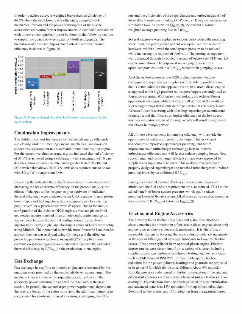
In order to achieve a cycle-weighted brake thermal efficiency of 46.6%, the indicated closed-cycle efficiency, pumping work, mechanical friction and the power consumption of the engine accessories all require further improvements. A detailed discussion of each improvement opportunity can be found in the following sections to support the quantitative estimates put forth in Figure 28. The breakdown of how each improvement affects the brake thermal efficiency is shown in Figure 30.
Figure 30. Future indicated closed-cycle efficiency improvements for the cycle average
Combustion ImprovementsThe ability to convert fuel energy to mechanical energy efficiently and cleanly while still meeting external mechanical and emission constraints is paramount to a successful internal combustion engine. For the current weighted average, a gross indicated thermal efficiency of 51.0% is achieved using a calibration with a maximum of 10 bar/deg maximum pressure rise rate, and a greater than 90% efficient SCR device that allows 2010 U.S. emissions requirements to be met with 3.3 g/kW-hr engine-out NOx.
Increasing the indicated thermal efficiency is a primary step toward increasing the brake thermal efficiency. In the present analysis, the effects of changes to the designed engine hardware on indicated thermal efficiency were evaluated using CFD results with new piston bowl shapes and fuel injector nozzle configurations. As a starting point, several new piston bowls were designed. Due to the unique configuration of the Achates OP2S engine, advanced piston bowl geometries require matched injector hole configuration and spray angles. To determine the optimal configuration of piston bowl, injector holes, spray angle, and clocking, a series of DoE's were setup using Minitab. Their potential to provide more favorable heat transfer and combustion was analyzed using Converge and the effect on piston temperatures were found using ANSYS. Together these combustion system upgrades are predicted to increase the indicated thermal efficiency by 0.7%fuel in the production intent engine
Gas ExchangeGas exchange losses for a two-stroke engine are represented by the pumping work provided by the crankshaft-driven supercharger. The mechanical losses to drive the supercharger are included in the accessory power consumption and will be discussed in the next section. In general, the supercharger power requirements depend on the pressure losses of the entire air system, the additional pumping to compensate for short-circuiting of air during scavenging, the EGR
rate and the efficiencies of the supercharger and turbocharger. All of these effects were quantified by GT-Power, a 1D engine performance simulation tool. As shown in Figure 28, the current measured weighted average pumping loss is 2.0%fuel.
Several measures were applied in succession to reduce the pumping work. First, the porting arrangement was optimized for the future hardware, which allowed the total system pressure to be reduced while increasing the trapped air-fuel ratio. The porting arrangement was optimized through a coupled iteration of open-cycle CFD and 1D engine simulations. The improved scavenging process from optimized ports resulted in a 0.6%fuel reduction in pumping losses.
As Achates Power moves to a 2020 production-intent engine configuration, supercharger suppliers will be able to produce a unit that is better suited for the opposed-piston, two-stroke diesel engine as opposed to the high pressure ratio superchargers currently used on four-stroke engines. With current technology, the Achates Power opposed-piston engine utilizes a very small portion of the available supercharger maps that is outside of the maximum efficiency island. Achates Power is working with a leading supercharger manufacture to design a unit that focuses on higher efficiency in the low speed, low pressure ratio portion of the map, which will result in significant reductions in pumping work.
All of these advancements in pumping efficiency will provide the opportunity to match a different turbocharger. Higher exhaust temperatures, improved supercharger pumping, and future improvements in turbocharger technology help to improve turbocharger efficiency and will further reduce pumping losses. New supercharger and turbocharger efficiency maps were approved by suppliers and input into GT-Power. This analysis revealed that a properly designed supercharger and matched turbocharger will reduce pumping losses by an additional 0.5%fuel.
Finally, as indicated thermal efficiency increases and losses are minimized, the fuel and air requirement are also reduced. This has the added benefit of lower system pressures which again reduces pumping losses of the air system. All of these advances drop pumping losses down to 0.7%fuel as shown in Figure 28.
Friction and Engine AccessoriesThe power cylinder friction (ring/liner and piston/liner friction) closely matches the situation in a four-stroke diesel engine, since both engine types employ a slider-crank mechanism. It is, therefore, a reasonable strategy to leverage the same industry-wide advancements in the area of tribology and advanced lubricants to lower the friction losses of the power cylinder in an opposed-piston engine. Friction improvements were determined from a variety of sources including supplier projections, in-house benchmark testing, and analysis tools such as AMESim and PISDYN. For this roadmap, the friction reduction for the power cylinder, bearings and geartrain are projected to be about 41% which divide up as follows: About 6% reduction from the power cylinder based on further optimization of the ring and piston skirt contours combined with advanced surface textures and/or coatings; 11% reduction from the bearings based on size optimization and advanced materials; 13% reduction from optimized oil/coolant flows and temperatures; and 11% reduction from the geartrain based
on optimized integrated geartrain design. Combined, the projected improvements total 2.7%fuel which drops total friction losses to 4.5%fuel as shown in Figure 28.
It is important to note that, as mentioned previously, these friction reductions help reduce fuel and air requirments which help reduce pumping losses. This contributes to the 3%fuel improvement in brake thermal efficiency from friction reductions seen in Figure 30.
Engine VibrationThe inherent vibration characteristics are an important consideration when evaluating engine architectures for any on-road application. The current heavy- and medium-duty market is dominated by inline six-cylinder, four-stroke engines. This baseline configuration features theoretically “perfect” force and moment balancing, with the only residual effect being the reaction from the engine output torque. Therefore, any un-cancelled residual forces or moments from the opposed-piston, two-stroke, three-cylinder engine will be an additional input to the engine mount system design.
The engine output torque reaction moments will be comparable to an inline six-cylinder, four-stroke engine with the same crank rotational speed and mean brake torque. This is because the frequency of the firing events is the same between both cases. The other assumptions in this statement are that the rotational inertias and peak cylinder pressures of the systems are comparable.
The opposed-piston architecture inherently balances out the majority of the piston acceleration forces within each cylinder. As the intake side piston decelerates towards the injector plane, the exhaust side piston also decelerates in a similar magnitude, but in the opposite direction. The only offset is a result of the phase shift between the two pistons. The exhaust piston is phased slightly ahead of the intake piston to maintain favorable intake to exhaust port time-areas and overall expansion ratio. As a result, there is a small residual piston inertial force from each cylinder.
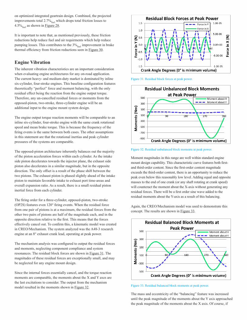
The firing order for a three-cylinder, opposed-piston, two-stroke (OP2S) features even 120° firing events. When the residual force from one pair of pistons is at a maximum, the residual forces from the other two pairs of pistons are half of the magnitude each, and in the opposite direction relative to the first. This means that the forces effectively cancel out. To confirm this, a kinematic model was created in CREO/Mechanism. The system analyzed was the A48-3 research engine at an 8° exhaust crank lead, operating at peak power.
The mechanism analysis was configured to output the residual forces and moments, neglecting component compliance and system resonances. The residual block forces are shown in Figure 31. The magnitudes of these residual forces are exceptionally small, and may be neglected for any engine mount design.
Since the internal forces essentially cancel, and the torque reaction moments are comparable, the moments about the X and Y axes are the last excitations to consider. The output from the mechanism model resulted in the moments shown in Figure 32.
Figure 31. Residual block forces at peak power.
Figure 32. Residual unbalanced block moments at peak power.
Moment magnitudes in this range are well within standard engine mount design capability. This characteristic curve features both first- and third-order content. Since the first-order content magnitude exceeds the third-order content, there is an opportunity to reduce the peak even below this reasonably low level. Adding equal and opposite masses to the end of one crank (or any shaft rotating at crank speed) will counteract the moment about the X-axis without generating any residual forces. There will be a first order sine wave added to the residual moments about the Y-axis as a result of this balancing.
Again, the CREO/Mechanism model was used to demonstrate this concept. The results are shown in Figure 33.
Figure 33. Residual balanced block moments at peak power.
The mass and eccentricity of the “balancing” feature was increased until the peak magnitude of the moments about the Y axis approached the peak magnitude of the moments about the X axis. Of course, if
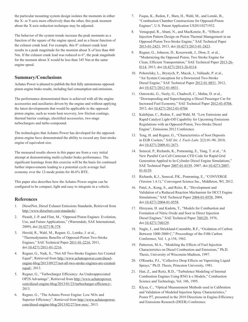
the particular mounting system design isolates the moments in either the X- or Y-axis more effectively than the other, this peak moment about the X-axis reduction technique may be adjusted.
The behavior of the system trends increase the peak moments as a function of the square of the engine speed, and as a linear function of the exhaust crank lead. For example, this 8° exhaust crank lead results in a peak magnitude for the moment about X of less than 460 Nm. If the exhaust crank lead was reduced to 6°, the peak magnitude for the moment about X would be less than 345 Nm at the same engine speed.
Summary/ConclusionsAchates Power is pleased to publish the first fully autonomous opposed-piston engine brake results, including fuel consumption and emissions.
The performance demonstrated there is achieved with all the engine accessories and auxiliaries driven by the engine and without applying the latest developments that would be applicable to the opposed-piston engine, such as waste heat recovery, low friction coatings, thermal barrier coatings, electrified accessories, two-stage turbochargers and turbo-compound.
The technologies that Achates Power has developed for the opposed-piston engine have demonstrated the ability to exceed any four-stroke engine of equivalent size.
The measured results shown in this paper are from a very initial attempt at demonstrating multi-cylinder brake performance. The significant learnings from this exercise will be the basis for continued further improvements leading to a potential cycle average fuel economy over the 12-mode points for 46.6% BTE.
This paper also describes how the Achates Power engine can be configured to be compact, light and easy to integrate in a vehicle.
References1. DieselNet, Diesel Exhaust Emissions Standards, Retrieved from
http://www.dieselnet.com/standards/.
2. Pirault, J.-P. and Flint, M., “Opposed Piston Engines: Evolution, Use, and Future Applications,” (Warrendale, SAE International, 2009), doi:10.4271/R-378.
3. Herold, R., Wahl, M., Regner, G., Lemke, J. et al., “Thermodynamic Benefits of Opposed-Piston Two-Stroke Engines,” SAE Technical Paper 2011-01-2216, 2011, doi:10.4271/2011-01-2216.
4. Regner, G., Naik, S., “Not All Two-Stroke Engines Are Created Equal”, Retrieved from http://www.achatespower.com/diesel-engine-blog/2013/09/27/not-all-two-stroke-engines-are-created-equal/, 2013.
5. Regner, G., “Turbocharger Efficiency: An Underappreciated OP2S Advantage”, Retrieved from http://www.achatespower.com/diesel-engine-blog/2013/01/23/turbocharger-efficiency/, 2013.
6. Regner, G., “The Achates Power Engine: Low NOx and Superior Efficiency”, Retrieved from http://www.achatespower.com/diesel-engine-blog/2013/02/27/low-nox/, 2013.
7. Fuqua, K., Redon, F., Shen, H., Wahl, M., and Lenski, B., “Combustion Chamber Constructions for Opposed-Piston Engines”, U.S. Patent Application US20110271932.
8. Venugopal, R., Abani, N., and MacKenzie, R., “Effects of Injection Pattern Design on Piston Thermal Management in an Opposed-Piston Two-Stroke Engine,” SAE Technical Paper 2013-01-2423, 2013, doi:10.4271/2013-01-2423.
9. Regner, G., Johnson, D., Koszewnik, J., Dion, E. et al., “Modernizing the Opposed Piston, Two Stroke Engine for Clean, Efficient Transportation,” SAE Technical Paper 2013-26-0114, 2013, doi:10.4271/2013-26-0114.
10. Pohorelsky, L., Brynych, P., Macek, J., Vallaude, P. et al., “Air System Conception for a Downsized Two-Stroke Diesel Engine,” SAE Technical Paper 2012-01-0831, 2012, doi:10.4271/2012-01-0831.
11. Ostrowski, G., Neely, G., Chadwell, C., Mehta, D. et al., “Downspeeding and Supercharging a Diesel Passenger Car for Increased Fuel Economy,” SAE Technical Paper 2012-01-0704, 2012, doi:10.4271/2012-01-0704.
12. Kalebjian, C., Redon, F., and Wahl, M. “Low Emissions and Rapid Catalyst Light-Off Capability for Upcoming Emissions Regulations with an Opposed-Piston, Two-Stroke Diesel Engine”, Emissions 2012 Conference.
13. Teng, H. and Regner, G., “Characteristics of Soot Deposits in EGR Coolers,” SAE Int. J. Fuels Lubr. 2(2):81-90, 2010, doi:10.4271/2009-01-2671.
14. Senecal, P., Richards, K., Pomraning, E., Yang, T. et al., “A New Parallel Cut-Cell Cartesian CFD Code for Rapid Grid Generation Applied to In-Cylinder Diesel Engine Simulations,” SAE Technical Paper 2007-01-0159, 2007, doi:10.4271/2007-01-0159.
15. Richards, K.J., Senecal, P.K., Pomraning, E., “CONVERGE (Version 1.4.1),” Convergent Science Inc., Middleton, WI, 2012.
16. Patel, A., Kong, S., and Reitz, R., “Development and Validation of a Reduced Reaction Mechanism for HCCI Engine Simulations,” SAE Technical Paper 2004-01-0558, 2004, doi:10.4271/2004-01-0558.
17. Hiroyasu, H. and Kadota, T., “Models for Combustion and Formation of Nitric Oxide and Soot in Direct Injection Diesel Engines,” SAE Technical Paper 760129, 1976, doi:10.4271/760129.
18. Nagle, J., and Strickland-Constable, R.F., “Oxidation of Carbon Between 1000-2000 C,” Proceedings of the Fifth Carbon Conference, Vol. 1, p.154, 1962.
19. Patterson, M.A., “Modeling the Effects of Fuel Injection Characteristics on Diesel Combustion and Emissions,” Ph.D. Thesis, University of Wisconsin-Madison, 1997.
20. O'Rourke, P.J., “Collective Drop Effects on Vaporizing Liquid Sprays,” Ph.D. Thesis, Princeton University, 1981.
21. Han, Z., and Reitz, R.D., “Turbulence Modeling of Internal Combustion Engines Using RNG k-ε Models,” Combustion Science and Technology, Vol. 106, 1995.
22. Klyza, C., “Optical Measurement Methods used in Calibration and Validation of Modeled Injection Spray Characteristics,” Poster P7, presented in the 2010 Directions in Engine-Efficiency and Emissions Research (DEER) Conference.

23. Naik, S., Johnson, D., Koszewnik, J., Fromm, L. et al., “Practical Applications of Opposed-Piston Engine Technology to Reduce Fuel Consumption and Emissions,” SAE Technical Paper 2013-01-2754, 2013, doi:10.4271/2013-01-2754.
Contact InformationSuramya NaikChief EngineerAchates Power, [email protected]
The Engineering Meetings Board has approved this paper for publication. It has successfully completed SAE’s peer review process under the supervision of the session organizer. The process requires a minimum of three (3) reviews by industry experts.
All rights reserved. No part of this publication may be reproduced, stored in a retrieval system, or transmitted, in any form or by any means, electronic, mechanical, photocopying, recording, or otherwise, without the prior written permission of SAE International.
Positions and opinions advanced in this paper are those of the author(s) and not necessarily those of SAE International. The author is solely responsible for the content of the paper.
ISSN 0148-7191
http://papers.sae.org/2015-26-0038