Embed Size (px)
Citation preview
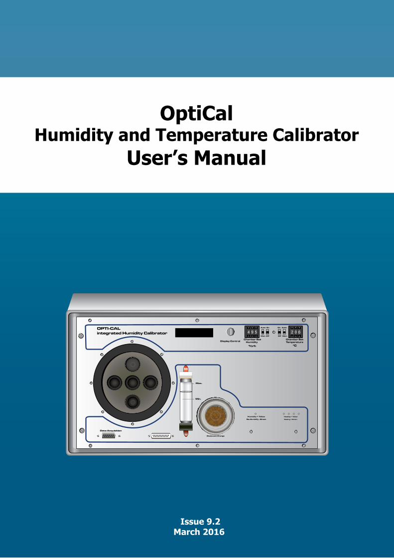
OptiCalHumidity and Temperature Calibrator
User’s Manual
Data Acquisition
Desiccant Charge
Humidity = Yellow
De-Humidify - Green
Heating = Yellow
Cooling = Green
Chamber Set HumidityDisplay Control
Chamber SetTemperature
%rh °C
Auto On On Auto
Man. Off Off Man.
OPTI-CALintegrated Humidity Calibrator
Max.
Min.
4 9 5 2 0 6
Issue 9.2 March 2016
OptiCal
OptiCalHumidity and
Temperature CalibratorUser’s Manual
KAHN INSTRUMENTS, INC
885 Wells Road, Wethersfield, CT 06109
Phone: 860-529-8643 Fax: 860-529-1895
E-mail: [email protected] www.kahn.com
OptiCal User’s Manual
Kahn Instruments, Inc. i
ContentsSafety ................................................................................................................................iii
Electrical Safety ...........................................................................................................iiiToxic Materials .............................................................................................................iiiRepair and Maintenance ...............................................................................................iiiCalibration ...................................................................................................................iii
Abbreviations ......................................................................................................................ivWarnings ............................................................................................................................iv
1 INTRODUCTION ................................................................................................11.1 Description ........................................................................................................ 11.2 System Components ........................................................................................... 21.2.1 Front Panel ........................................................................................................ 2
2 INSTALLATION ..................................................................................................42.1 Installing the Relative Humidity and Temperature Control Probes ........................... 42.2 Filling the Water Reservoir .................................................................................. 62.3 Draining the Water Reservoir ............................................................................... 72.4 Desiccant .......................................................................................................... 82.5 Power Supply ..................................................................................................... 9
3 OPERATION ....................................................................................................103.1 Preparation ...................................................................................................... 103.1.1 Installing Relative Humidity Instruments for Calibration ................................. 103.2 Start-Up ........................................................................................................... 113.3 Local Control of Chamber Temperature and Humidity Set Points........................... 113.4 Remote Control of Chamber Temperature and Humidity Set Points ....................... 123.4.1 Digital Communications ............................................................................... 123.4.2 Putting the Optidew in Remote Mode............................................................ 133.4.3 Remote Control - Manual Set Point Control ................................................... 133.4.4 Remote Control - Automatic Set Point Control ............................................... 133.5 Typical Response Times for Various Step Changes ............................................... 143.6 Control Outputs ................................................................................................ 15
4 OPTIDEW REFERENCE INSTRUMENT ................................................................164.1 Optidew Display ............................................................................................... 164.1.1 Selecting Which ‘Screen’ to View on the Display ............................................ 164.1.2 Description of Screens 1- 8 .......................................................................... 174.2 Maintenance .................................................................................................... 194.2.1 Removing the Chilled Mirror Reference Sensor for Mirror Cleaning .................. 194.2.2 Sensor Mirror Cleaning ................................................................................ 204.2.3 Resetting the Mirror Condition ...................................................................... 214.2.4 Re-calibration of the Chilled Mirror Reference ................................................ 22
5 APPLICATION SOFTWARE ................................................................................235.1 Virtual Hygrometer ........................................................................................... 235.2 OptiCal Remote Chamber Control ...................................................................... 245.3 Parameter Setup .............................................................................................. 245.4 Charting and Logging ....................................................................................... 265.5 Statistics .......................................................................................................... 285.6 Control Parameters ........................................................................................... 285.7 Calibration Correction ....................................................................................... 295.8 Change of Password ......................................................................................... 31
6 TROUBLESHOOTING ........................................................................................32
OptiCal User’s Manual
ii 97079 Issue 9.2, March 2016
FiguresFigure 1 OptiCal - Front View ...................................................................................2Figure 2 OptiCal - Back Panel ...................................................................................3Figure 3 Probe Installation .......................................................................................4Figure 4 Location of Probes Inside the Climate Chamber ............................................5Figure 5 Filling the Water Reservoir ..........................................................................6Figure 6 Emptying the Water Reservoir .....................................................................7Figure 7 Desiccant Replacement ...............................................................................8Figure 8 Level of Silica Gel Required .........................................................................8Figure 9 Probe Ports ..............................................................................................10Figure 10 Port Adapter Removal Tool ........................................................................10Figure 11 Port Adapters and Removal Tool ................................................................10Figure 12 Humidity and Temperature Setting Switches ...............................................11Figure 13 Humidity and Temperature Setting Switches ...............................................12Figure 14 OptiCal Manual Control .............................................................................13Figure 15 OptiCal Programming ................................................................................13Figure 16 Optidew Chilled Mirror Reference Display and Navigation ............................18Figure 17 Lid Screw Locations ..................................................................................19Figure 18 Sensor Mirror Cleaning ..............................................................................20Figure 19 Potentiometer Location .............................................................................21Figure 20 Virtual Hygrometer Window ......................................................................23Figure 21 Parameter Setup Window ..........................................................................24Figure 22 Chart/Log Control Panel Window ...............................................................26Figure 23 Chart Window ..........................................................................................27Figure 24 Basic Statistics Window .............................................................................28Figure 25 Extracts From Calibration Certificates .........................................................29Figure 26 Calibration Correction Window ...................................................................31Figure 27 Change Password Window ........................................................................31
TablesTable 1 Typical Response Times for Step Changes ...................................................14
Appendices
Appendix A Technical Specifications ..............................................................................34Appendix B EU Declaration of Conformity......................................................................36
OptiCal User’s Manual
Kahn Instruments, Inc. iii
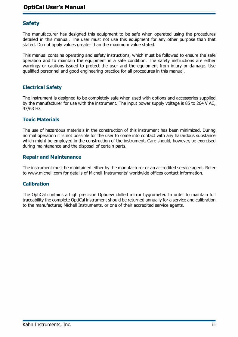
Safety
The manufacturer has designed this equipment to be safe when operated using the procedures detailed in this manual. The user must not use this equipment for any other purpose than that stated. Do not apply values greater than the maximum value stated.
This manual contains operating and safety instructions, which must be followed to ensure the safe operation and to maintain the equipment in a safe condition. The safety instructions are either warnings or cautions issued to protect the user and the equipment from injury or damage. Use qualified personnel and good engineering practice for all procedures in this manual.
Electrical Safety
The instrument is designed to be completely safe when used with options and accessories supplied by the manufacturer for use with the instrument. The input power supply voltage is 85 to 264 V AC, 47/63 Hz.
Toxic Materials
The use of hazardous materials in the construction of this instrument has been minimized. During normal operation it is not possible for the user to come into contact with any hazardous substance which might be employed in the construction of the instrument. Care should, however, be exercised during maintenance and the disposal of certain parts.
Repair and Maintenance
The instrument must be maintained either by the manufacturer or an accredited service agent. Refer to www.michell.com for details of Michell Instruments’ worldwide offices contact information.
Calibration
The OptiCal contains a high precision Optidew chilled mirror hygrometer. In order to maintain full traceability the complete OptiCal instrument should be returned annually for a service and calibration to the manufacturer, Michell Instruments, or one of their accredited service agents.
OptiCal User’s Manual
iv 97079 Issue 9.2, March 2016
Abbreviations
The following abbreviations are used in this manual:
°C degrees Celsius°F degrees FahrenheitAC alternating currentDC direct currentcm3 cubic centimetersgkg-1 grams per kilogramgm-3 grams per cubic meterHz Hertzin inch(es)in3 cubic incheskg kilogramlbs poundsmA milli Amperemax maximummin minimummm millimeterN/C normally closedN/O normally open% percentage RH relative humidityRS232 serial data transmission standardT temperatureUSB Universal Serial BusV Volts
Warnings
The following general warning listed below is applicable to this instrument. It is repeated in the text in the appropriate locations.
Where this hazard warning symbol appears in the following sections it is used to indicate areas where potentially hazardous
operations need to be carried out.
OptiCal User’s Manual
Kahn Instruments, Inc. 1
INTRODUCTION
1 INTRODUCTION
1.1 Description
The Kahn OptiCal is a stable and accurate calibration solution for humidity sensors over the 10 to 90%RH and +10 to +50 (+50°C to +122°F) range. The stand-alone, transportable calibrator requires no external services other than line power, and features an integrated chilled mirror reference instrument to enable the operator to perform calibrations that are traceable to national standards.
The calibration chamber features five interchangeable ports to accommodate virtually any brand, type or model of sensor. The environment within the insulated calibration chamber is temperature controlled using a four-zone fan-assisted peltier arrangement for maximum stability and minimum temperature gradient. The humidity of the circulating air is precisely regulated using a closed-loop control system that functions by proportionally mixing flows of dry and saturated air.
A bright and clear VFD (vacuum fluorescent display) displays the parameters measured by the reference instrument in various relative and absolute humidity units, alongside the temperature within the chamber.
The humidity and temperature set-points can be controlled either manually or automatically as part of a calibration program. Manual control is achieved by the switches on the front panel. Response time to a humidity or temperature step change is typically quicker than ten minutes. The supplied application software allows calibration programs to be created, enabling automatic time-based control of temperature and humidity set points. The software also allows the user to monitor, chart and log calibration reference data on a PC for later analysis.
The desiccant changes color to indicate when it needs to be recharged, and is visible through a clear window on the front of the unit. Recharge the desiccant following the instructions in Section 2.4. The water reservoir at the front of the unit shows the current saturator fill level, and makes it easy to top up with distilled water when required (refer to Section 2.2). Apart from periodic calibration of the chilled mirror reference, no other maintenance is necessary. The only external service required is a single phase power supply.
OptiCal User’s Manual
2 97079 Issue 9.2, March 2016
INTRODUCTION
1.2 System Components
1.2.1 Front Panel
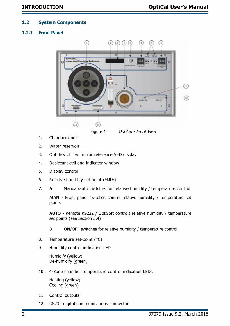
Figure 1 OptiCal - Front View1. Chamber door
2. Water reservoir
3. Optidew chilled mirror reference VFD display
4. Desiccant cell and indicator window
5. Display control
6. Relative humidity set point (%RH)
7. A Manual/auto switches for relative humidity / temperature control
MAN - Front panel switches control relative humidity / temperature set points
AUTO - Remote RS232 / OptiSoft controls relative humidity / temperature set points (see Section 3.4)
B ON/OFF switches for relative humidity / temperature control
8. Temperature set-point (°C)
9. Humidity control indication LED
Humidify (yellow)De-humidify (green)
10. 4-Zone chamber temperature control indication LEDs
Heating (yellow)Cooling (green)
11. Control outputs
12. RS232 digital communications connector
OptiCal User’s Manual
Kahn Instruments, Inc. 3
INTRODUCTION
Back Panel
31
4
Remote Communications
Optics Adjustment
On
Off
2
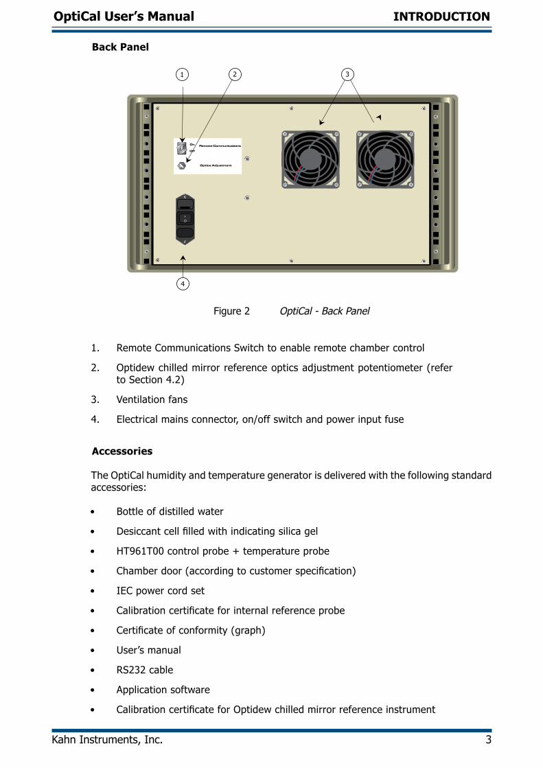
Figure 2 OptiCal - Back Panel
1. Remote Communications Switch to enable remote chamber control
2. Optidew chilled mirror reference optics adjustment potentiometer (refer to Section 4.2)
3. Ventilation fans
4. Electrical mains connector, on/off switch and power input fuse
Accessories
The OptiCal humidity and temperature generator is delivered with the following standard accessories:
• Bottle of distilled water
• Desiccant cell filled with indicating silica gel
• HT961T00 control probe + temperature probe
• Chamber door (according to customer specification)
• IEC power cord set
• Calibration certificate for internal reference probe
• Certificate of conformity (graph)
• User’s manual
• RS232 cable
• Application software
• Calibration certificate for Optidew chilled mirror reference instrument
OptiCal User’s Manual
4 97079 Issue 9.2, March 2016
INSTALLATION
2 INSTALLATION
Before using the OptiCal make sure that Sections 2.1, 2.2 and 2.4 are read thoroughly.
The OptiCal enclosure is designed for bench top mounting in a laboratory type environment. It must be positioned in a clean and level location with sufficient clearance at the rear of the enclosure for adequate ventilation.
The OptiCal is not designed to be fully portable. However, it can easily be moved to any suitable location for use. Before moving,
insure that any water in the reservoir is drained and that the RH control probe and the temperature probe in the chamber are
removed.
The OptiCal should NOT be moved while in operation.
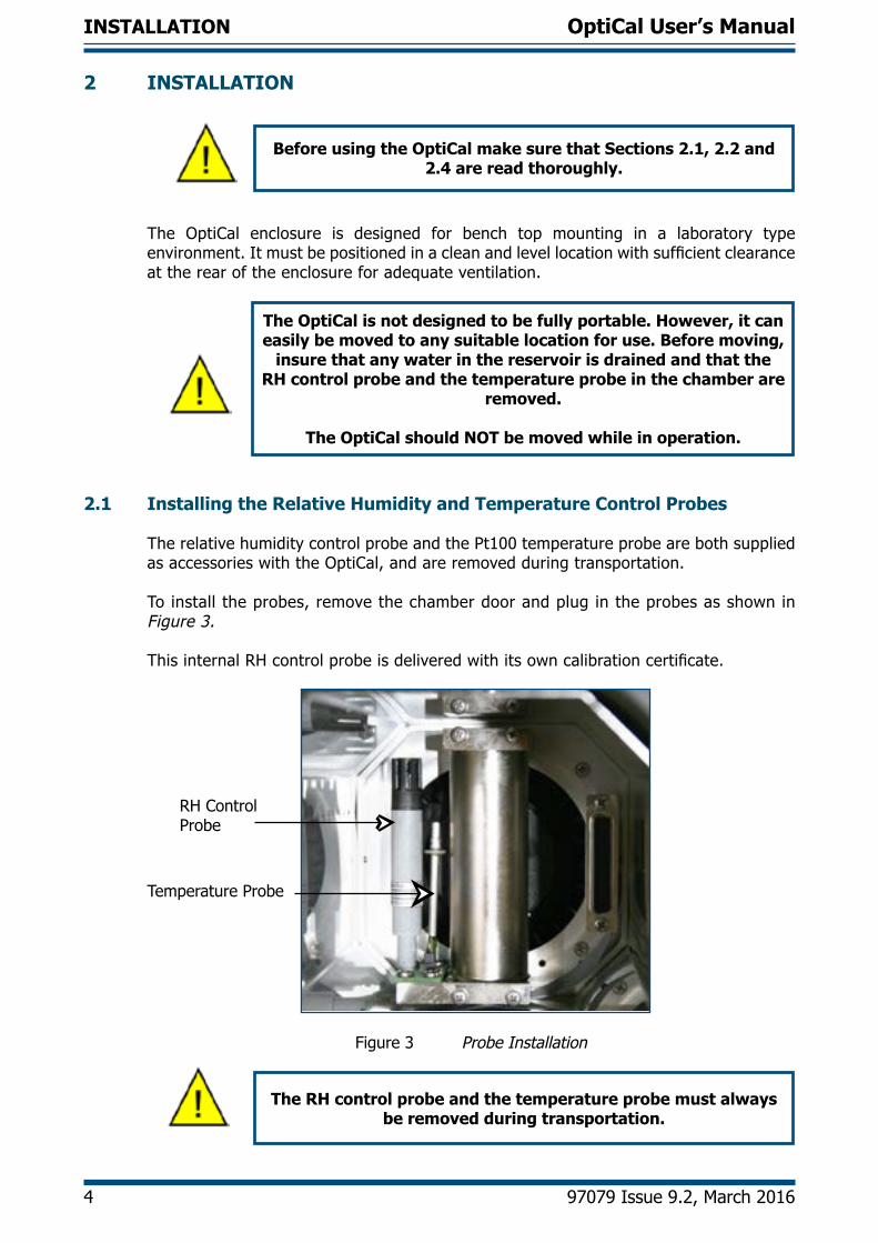
2.1 Installing the Relative Humidity and Temperature Control Probes
The relative humidity control probe and the Pt100 temperature probe are both supplied as accessories with the OptiCal, and are removed during transportation.
To install the probes, remove the chamber door and plug in the probes as shown in Figure 3.
This internal RH control probe is delivered with its own calibration certificate.
RH Control Probe
Temperature Probe
Figure 3 Probe Installation
The RH control probe and the temperature probe must always be removed during transportation.
OptiCal User’s Manual
Kahn Instruments, Inc. 5
INSTALLATION
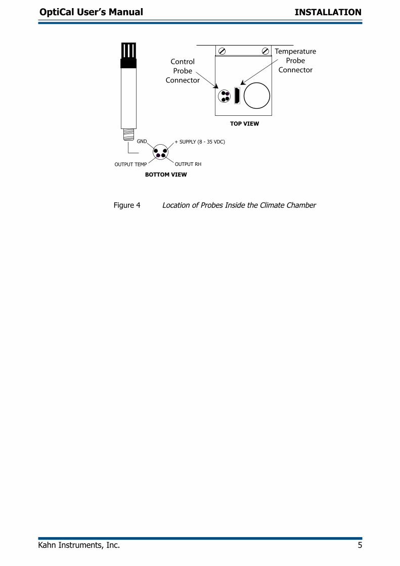
GND
OUTPUT TEMP
+ SUPPLY (8 - 35 VDC)
OUTPUT RH
BOTTOM VIEW
TOP VIEW
ControlProbe
Connector
TemperatureProbe
Connector
Figure 4 Location of Probes Inside the Climate Chamber
OptiCal User’s Manual
6 97079 Issue 9.2, March 2016
INSTALLATION
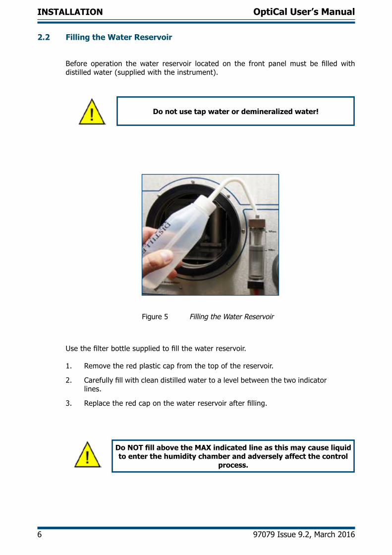
2.2 Filling the Water Reservoir
Before operation the water reservoir located on the front panel must be filled with distilled water (supplied with the instrument).
Do not use tap water or demineralized water!
Figure 5 Filling the Water Reservoir
Use the filter bottle supplied to fill the water reservoir.
1. Remove the red plastic cap from the top of the reservoir.
2. Carefully fill with clean distilled water to a level between the two indicator lines.
3. Replace the red cap on the water reservoir after filling.
Do NOT fill above the MAX indicated line as this may cause liquid to enter the humidity chamber and adversely affect the control
process.
OptiCal User’s Manual
Kahn Instruments, Inc. 7
INSTALLATION
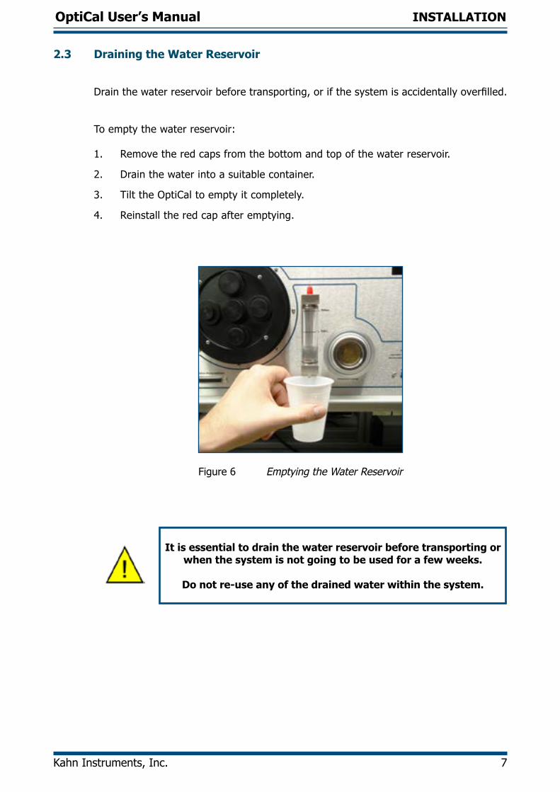
2.3 Draining the Water Reservoir
Drain the water reservoir before transporting, or if the system is accidentally overfilled.
To empty the water reservoir:
1. Remove the red caps from the bottom and top of the water reservoir.
2. Drain the water into a suitable container.
3. Tilt the OptiCal to empty it completely.
4. Reinstall the red cap after emptying.
Figure 6 Emptying the Water Reservoir
It is essential to drain the water reservoir before transporting or when the system is not going to be used for a few weeks.
Do not re-use any of the drained water within the system.
OptiCal User’s Manual
8 97079 Issue 9.2, March 2016
INSTALLATION
2.4 Desiccant
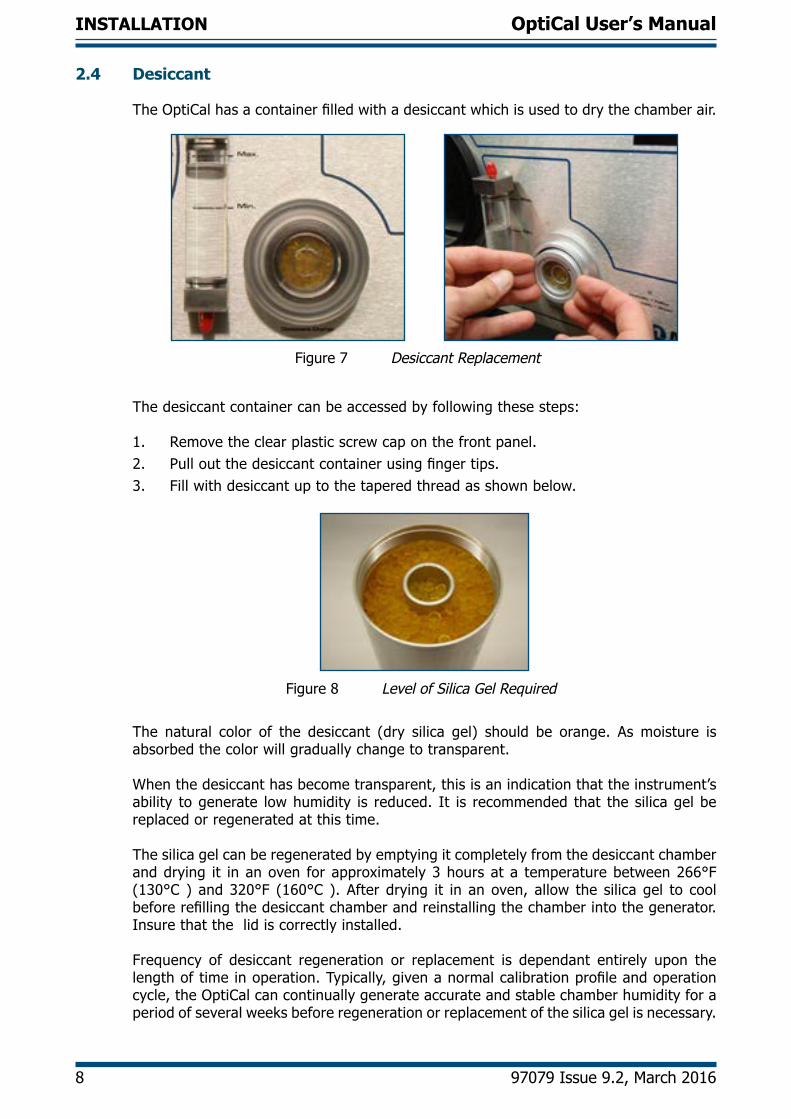
The OptiCal has a container filled with a desiccant which is used to dry the chamber air.
Figure 7 Desiccant Replacement
The desiccant container can be accessed by following these steps:
1. Remove the clear plastic screw cap on the front panel.2. Pull out the desiccant container using finger tips.3. Fill with desiccant up to the tapered thread as shown below.
Figure 8 Level of Silica Gel Required
The natural color of the desiccant (dry silica gel) should be orange. As moisture is absorbed the color will gradually change to transparent.
When the desiccant has become transparent, this is an indication that the instrument’s ability to generate low humidity is reduced. It is recommended that the silica gel be replaced or regenerated at this time. The silica gel can be regenerated by emptying it completely from the desiccant chamber and drying it in an oven for approximately 3 hours at a temperature between 266°F (130°C ) and 320°F (160°C ). After drying it in an oven, allow the silica gel to cool before refilling the desiccant chamber and reinstalling the chamber into the generator. Insure that the lid is correctly installed.
Frequency of desiccant regeneration or replacement is dependant entirely upon the length of time in operation. Typically, given a normal calibration profile and operation cycle, the OptiCal can continually generate accurate and stable chamber humidity for a period of several weeks before regeneration or replacement of the silica gel is necessary.
OptiCal User’s Manual
Kahn Instruments, Inc. 9
INSTALLATION
2.5 Power Supply
An AC power supply between 85 to 264 V AC is required to operate the unit.
The power supply connection is a 3 pin IEC plug located on the rear panel of the instrument. The ON/OFF switch and the power input fuse are in the same location, adjacent to the power socket.
A 3-core power cable is provided, the free end of which should be wired to a suitable earthed plug or directly connected via a fused power spur. The power cable conductors are color coded according to the international convention:
Brown L (Live)Blue N (Neutral)Green/Yellow E (Ground)
The instrument must be connected to an electrical ground for safety purposes.
OptiCal User’s Manual
10 97079 Issue 9.2, March 2016
OPERATION
3 OPERATION
3.1 Preparation
3.1.1 Installing Relative Humidity Instruments for Calibration
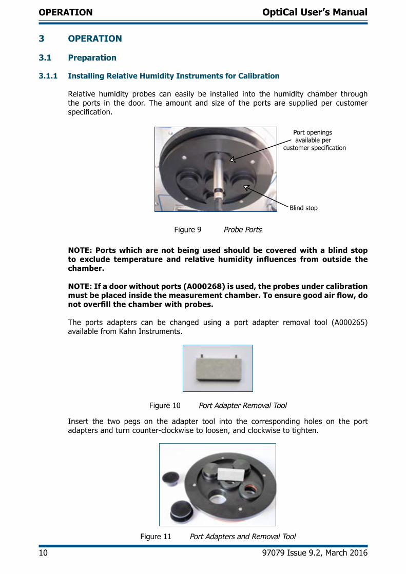
Relative humidity probes can easily be installed into the humidity chamber through the ports in the door. The amount and size of the ports are supplied per customer specification.
Port openings available per customer specification
Blind stop
Figure 9 Probe Ports
NOTE: Ports which are not being used should be covered with a blind stop to exclude temperature and relative humidity influences from outside the chamber.
NOTE: If a door without ports (A000268) is used, the probes under calibration must be placed inside the measurement chamber. To ensure good air flow, do not overfill the chamber with probes.
The ports adapters can be changed using a port adapter removal tool (A000265) available from Kahn Instruments.
Figure 10 Port Adapter Removal Tool
Insert the two pegs on the adapter tool into the corresponding holes on the port adapters and turn counter-clockwise to loosen, and clockwise to tighten.
Figure 11 Port Adapters and Removal Tool
OptiCal User’s Manual
Kahn Instruments, Inc. 11
OPERATION
3.2 Start-Up
After installing the calibration instruments, switch on the OptiCal by using the ON/OFF switch on the rear panel of the instrument.
3.3 Local Control of Chamber Temperature and Humidity Set Points
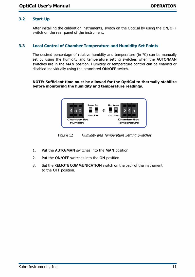
The desired percentage of relative humidity and temperature (in °C) can be manually set by using the humidity and temperature setting switches when the AUTO/MAN switches are in the MAN position. Humidity or temperature control can be enabled or disabled individually using the associated ON/OFF switch.
NOTE: Sufficient time must be allowed for the OptiCal to thermally stabilize before monitoring the humidity and temperature readings.
Chamber Set Humidity
Chamber SetTemperature
Auto On On Auto
Man. Off Off Man.
2 4 54 5 0
Figure 12 Humidity and Temperature Setting Switches
1. Put the AUTO/MAN switches into the MAN position.
2. Put the ON/OFF switches into the ON position.
3. Set the REMOTE COMMUNICATION switch on the back of the instrument to the OFF position.
OptiCal User’s Manual
12 97079 Issue 9.2, March 2016
OPERATION
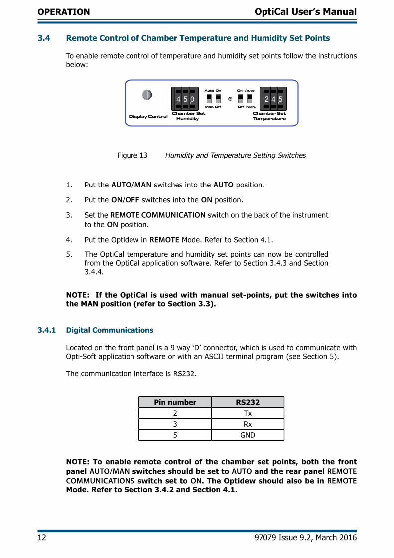
3.4 Remote Control of Chamber Temperature and Humidity Set Points
To enable remote control of temperature and humidity set points follow the instructions below:
Chamber Set Humidity
Chamber SetTemperature
Auto On On Auto
Man. Off Off Man.
2 4 54 5 0
Display Control
Figure 13 Humidity and Temperature Setting Switches
1. Put the AUTO/MAN switches into the AUTO position.
2. Put the ON/OFF switches into the ON position.
3. Set the REMOTE COMMUNICATION switch on the back of the instrument to the ON position.
4. Put the Optidew in REMOTE Mode. Refer to Section 4.1.
5. The OptiCal temperature and humidity set points can now be controlled from the OptiCal application software. Refer to Section 3.4.3 and Section 3.4.4.
NOTE: If the OptiCal is used with manual set-points, put the switches into the MAN position (refer to Section 3.3).
3.4.1 Digital Communications
Located on the front panel is a 9 way ‘D’ connector, which is used to communicate with Opti-Soft application software or with an ASCII terminal program (see Section 5).
The communication interface is RS232.
Pin number RS2322 Tx3 Rx5 GND
NOTE: To enable remote control of the chamber set points, both the front panel AUTO/MAN switches should be set to AUTO and the rear panel REMOTE COMMUNICATIONS switch set to ON. The Optidew should also be in REMOTE Mode. Refer to Section 3.4.2 and Section 4.1.
OptiCal User’s Manual
Kahn Instruments, Inc. 13
OPERATION
3.4.2 Putting the Optidew in Remote Mode
On start-up, the Optidew reference is automatically in LOCAL Mode. Once the display has stopped showing the start-up banner it is possible to change between the two modes by simply holding down the DISPLAY CONTROL button for approximately 7 seconds. In REMOTE Mode the display will show REMOTE MODE, indicating that communication with a PC via the RS232 port is possible.
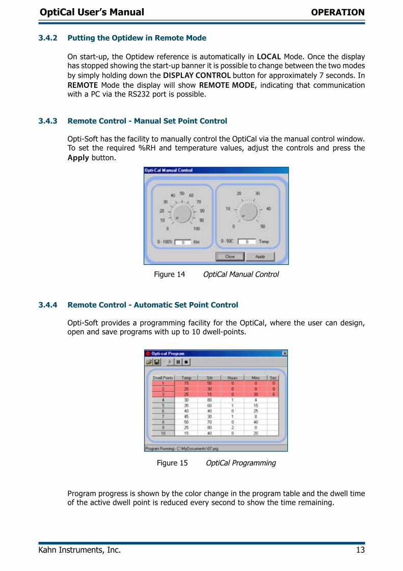
3.4.3 Remote Control - Manual Set Point Control
Opti-Soft has the facility to manually control the OptiCal via the manual control window. To set the required %RH and temperature values, adjust the controls and press the Apply button.
Figure 14 OptiCal Manual Control
3.4.4 Remote Control - Automatic Set Point Control
Opti-Soft provides a programming facility for the OptiCal, where the user can design, open and save programs with up to 10 dwell-points.
Figure 15 OptiCal Programming
Program progress is shown by the color change in the program table and the dwell time of the active dwell point is reduced every second to show the time remaining.
OptiCal User’s Manual
14 97079 Issue 9.2, March 2016
OPERATION
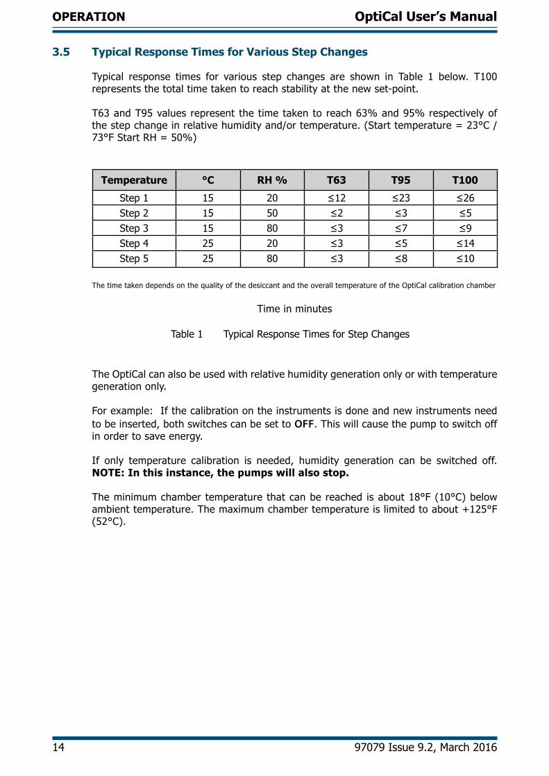
3.5 Typical Response Times for Various Step Changes
Typical response times for various step changes are shown in Table 1 below. T100 represents the total time taken to reach stability at the new set-point.
T63 and T95 values represent the time taken to reach 63% and 95% respectively of the step change in relative humidity and/or temperature. (Start temperature = 23°C / 73°F Start RH = 50%)
Temperature °C RH % T63 T95 T100
Step 1 15 20 ≤12 ≤23 ≤26Step 2 15 50 ≤2 ≤3 ≤5Step 3 15 80 ≤3 ≤7 ≤9Step 4 25 20 ≤3 ≤5 ≤14Step 5 25 80 ≤3 ≤8 ≤10
•
The time taken depends on the quality of the desiccant and the overall temperature of the OptiCal calibration chamber
Time in minutes
Table 1 Typical Response Times for Step Changes
The OptiCal can also be used with relative humidity generation only or with temperature generation only.
For example: If the calibration on the instruments is done and new instruments need to be inserted, both switches can be set to OFF. This will cause the pump to switch off in order to save energy.
If only temperature calibration is needed, humidity generation can be switched off. NOTE: In this instance, the pumps will also stop.
The minimum chamber temperature that can be reached is about 18°F (10°C) below ambient temperature. The maximum chamber temperature is limited to about +125°F (52°C).
OptiCal User’s Manual
Kahn Instruments, Inc. 15
OPERATION
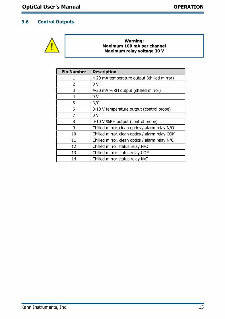
3.6 Control Outputs
Warning: Maximum 100 mA per channel Maximum relay voltage 30 V
Pin Number Description1 4-20 mA temperature output (chilled mirror)2 0 V3 4-20 mA %RH output (chilled mirror)4 0 V5 N/C6 0-10 V temperature output (control probe)7 0 V8 0-10 V %RH output (control probe)9 Chilled mirror, clean optics / alarm relay N/O10 Chilled mirror, clean optics / alarm relay COM11 Chilled mirror, clean optics / alarm relay N/C12 Chilled mirror status relay N/O13 Chilled mirror status relay COM14 Chilled mirror status relay N/C
OptiCal User’s Manual
16 97079 Issue 9.2, March 2016
OPTIDEW
4 OPTIDEW REFERENCE INSTRUMENT
The OptiCal is supplied with an integrated Optidew chilled mirror reference instrument to provide a fundamental and traceable reference measurement of the humidity within the chamber, while being totally independent from the controlling relative humidity probe. The advantage of this technique is to isolate the control of the chamber from the control system of the chilled mirror sensor to provide a fast responding and highly stable system.
4.1 Optidew Display
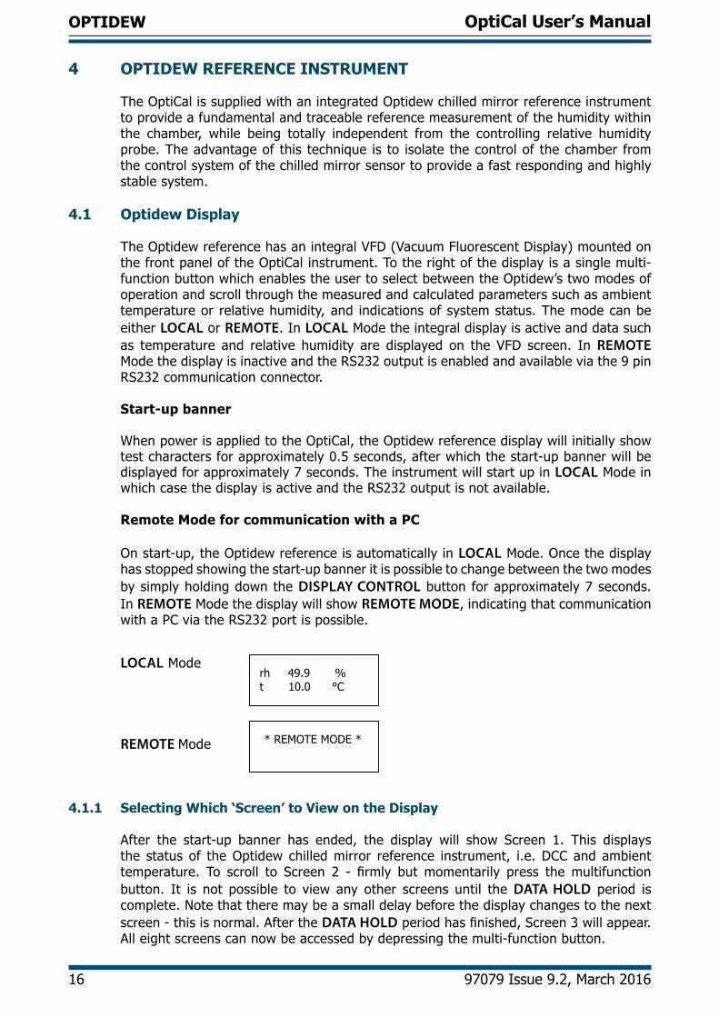
The Optidew reference has an integral VFD (Vacuum Fluorescent Display) mounted on the front panel of the OptiCal instrument. To the right of the display is a single multi-function button which enables the user to select between the Optidew’s two modes of operation and scroll through the measured and calculated parameters such as ambient temperature or relative humidity, and indications of system status. The mode can be either LOCAL or REMOTE. In LOCAL Mode the integral display is active and data such as temperature and relative humidity are displayed on the VFD screen. In REMOTE Mode the display is inactive and the RS232 output is enabled and available via the 9 pin RS232 communication connector.
Start-up banner
When power is applied to the OptiCal, the Optidew reference display will initially show test characters for approximately 0.5 seconds, after which the start-up banner will be displayed for approximately 7 seconds. The instrument will start up in LOCAL Mode in which case the display is active and the RS232 output is not available.
Remote Mode for communication with a PC
On start-up, the Optidew reference is automatically in LOCAL Mode. Once the display has stopped showing the start-up banner it is possible to change between the two modes by simply holding down the DISPLAY CONTROL button for approximately 7 seconds. In REMOTE Mode the display will show REMOTE MODE, indicating that communication with a PC via the RS232 port is possible.
* REMOTE MODE *
rh 49.9 %t 10.0 °C
LOCAL Mode
REMOTE Mode
4.1.1 Selecting Which ‘Screen’ to View on the Display
After the start-up banner has ended, the display will show Screen 1. This displays the status of the Optidew chilled mirror reference instrument, i.e. DCC and ambient temperature. To scroll to Screen 2 - firmly but momentarily press the multifunction button. It is not possible to view any other screens until the DATA HOLD period is complete. Note that there may be a small delay before the display changes to the next screen - this is normal. After the DATA HOLD period has finished, Screen 3 will appear. All eight screens can now be accessed by depressing the multi-function button.
OptiCal User’s Manual
Kahn Instruments, Inc. 17
OPTIDEW
4.1.2 Description of Screens 1- 8
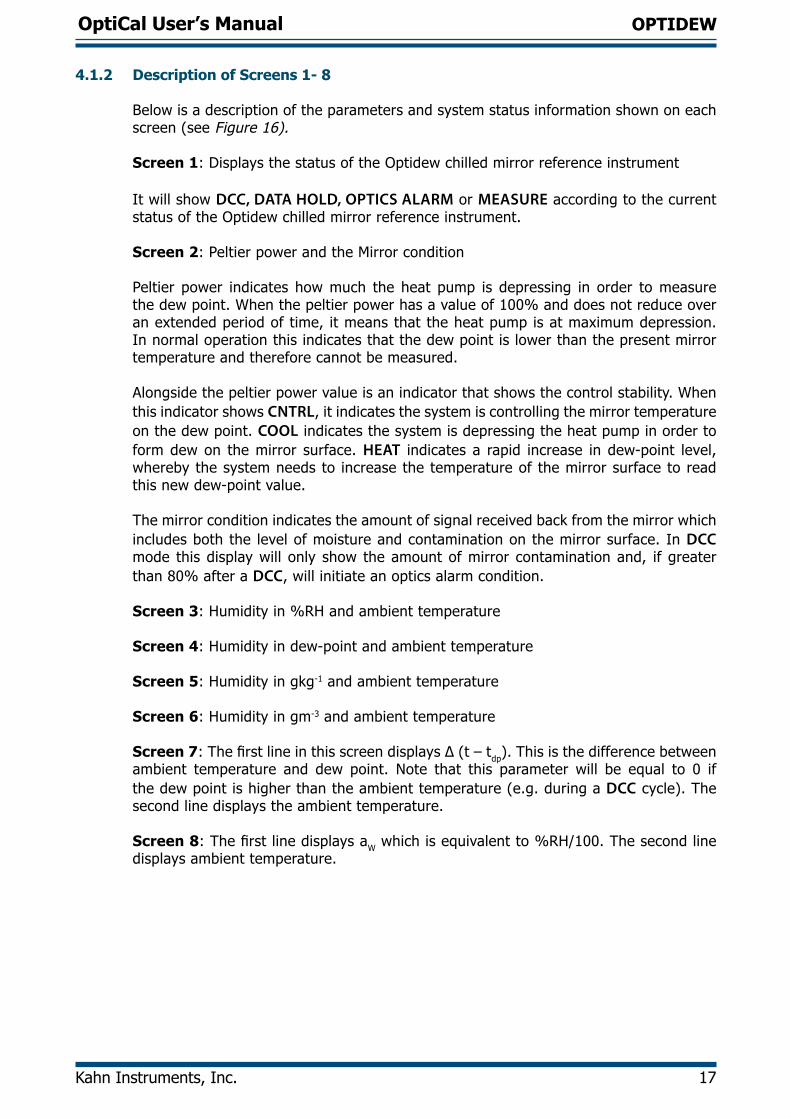
Below is a description of the parameters and system status information shown on each screen (see Figure 16).
Screen 1: Displays the status of the Optidew chilled mirror reference instrument
It will show DCC, DATA HOLD, OPTICS ALARM or MEASURE according to the current status of the Optidew chilled mirror reference instrument.
Screen 2: Peltier power and the Mirror condition
Peltier power indicates how much the heat pump is depressing in order to measure the dew point. When the peltier power has a value of 100% and does not reduce over an extended period of time, it means that the heat pump is at maximum depression. In normal operation this indicates that the dew point is lower than the present mirror temperature and therefore cannot be measured.
Alongside the peltier power value is an indicator that shows the control stability. When this indicator shows CNTRL, it indicates the system is controlling the mirror temperature on the dew point. COOL indicates the system is depressing the heat pump in order to form dew on the mirror surface. HEAT indicates a rapid increase in dew-point level, whereby the system needs to increase the temperature of the mirror surface to read this new dew-point value.
The mirror condition indicates the amount of signal received back from the mirror which includes both the level of moisture and contamination on the mirror surface. In DCC mode this display will only show the amount of mirror contamination and, if greater than 80% after a DCC, will initiate an optics alarm condition.
Screen 3: Humidity in %RH and ambient temperature
Screen 4: Humidity in dew-point and ambient temperature
Screen 5: Humidity in gkg-1 and ambient temperature
Screen 6: Humidity in gm-3 and ambient temperature
Screen 7: The first line in this screen displays Δ (t – tdp). This is the difference between ambient temperature and dew point. Note that this parameter will be equal to 0 if the dew point is higher than the ambient temperature (e.g. during a DCC cycle). The second line displays the ambient temperature.
Screen 8: The first line displays aW which is equivalent to %RH/100. The second line displays ambient temperature.
OptiCal User’s Manual
18 97079 Issue 9.2, March 2016
OPTIDEW
Apply Power
Optidew TransmitterInitialising
Status = MEASURE
Mirror: 50%Peltier: 40% COOL
rh 49.9 %t 10.0 °C
tdp 0.0 °Ct 10.0 °C
Y 106.00 gkg-1t 10.0 °C
dv 106.00 gm-3t 10.0 °C
(t-tdp) 10.0 °Ct 10.0 °C
aw 0.5t 10.0 °C
During DCC, Holdand Optics Alarm
Start upbanner
Screen 1
Screen 2
Screen 3
Screen 4
Screen 5
Screen 6
Screen 7
Screen 8
Figure 16 Optidew Chilled Mirror Reference Display and Navigation
OptiCal User’s Manual
Kahn Instruments, Inc. 19
OPTIDEW
4.2 Maintenance
! Failure to follow these maintenance procedures may result in premature wear or damage to the heat pump.
4.2.1 Removing the Chilled Mirror Reference Sensor for Mirror Cleaning
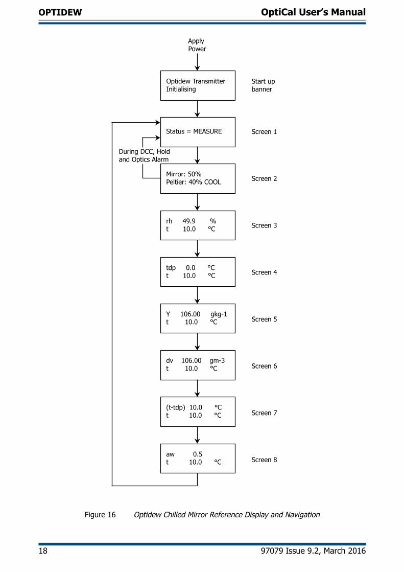
1. Remove the 4 screws securing the top lid to the OptiCal.
Figure 17 Lid Screw Locations
2. Disconnect the sensor cable from the Optidew sensor.
3. Unscrew the Optidew sensor from the side of the chamber.
4. Clean the sensor mirror according to the instructions in the next section.
OptiCal User’s Manual
20 97079 Issue 9.2, March 2016
OPTIDEW
4.2.2 Sensor Mirror Cleaning
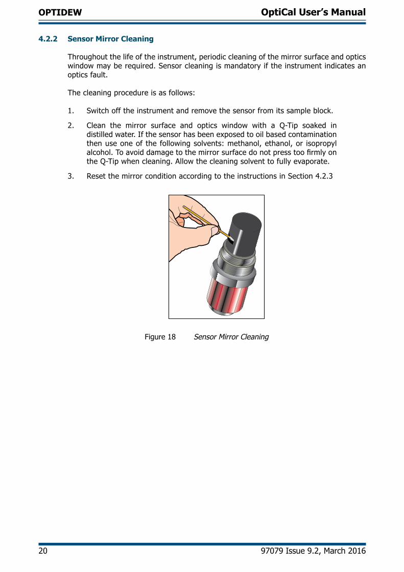
Throughout the life of the instrument, periodic cleaning of the mirror surface and opticswindow may be required. Sensor cleaning is mandatory if the instrument indicates an optics fault.
The cleaning procedure is as follows:
1. Switch off the instrument and remove the sensor from its sample block.
2. Clean the mirror surface and optics window with a Q-Tip soaked in distilled water. If the sensor has been exposed to oil based contamination then use one of the following solvents: methanol, ethanol, or isopropyl alcohol. To avoid damage to the mirror surface do not press too firmly on the Q-Tip when cleaning. Allow the cleaning solvent to fully evaporate.
3. Reset the mirror condition according to the instructions in Section 4.2.3
Figure 18 Sensor Mirror Cleaning
OptiCal User’s Manual
Kahn Instruments, Inc. 21
OPTIDEW
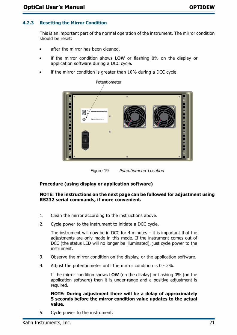
4.2.3 Resetting the Mirror Condition
This is an important part of the normal operation of the instrument. The mirror condition should be reset:
• after the mirror has been cleaned.
• if the mirror condition shows LOW or flashing 0% on the display or application software during a DCC cycle.
• if the mirror condition is greater than 10% during a DCC cycle.
Remote Communications
Optics Adjustment
On
Off
Potentiometer
Figure 19 Potentiometer Location
Procedure (using display or application software)
NOTE: The instructions on the next page can be followed for adjustment using RS232 serial commands, if more convenient.
1. Clean the mirror according to the instructions above.
2. Cycle power to the instrument to initiate a DCC cycle.
The instrument will now be in DCC for 4 minutes – it is important that the adjustments are only made in this mode. If the instrument comes out of DCC (the status LED will no longer be illuminated), just cycle power to the instrument.
3. Observe the mirror condition on the display, or the application software.
4. Adjust the potentiometer until the mirror condition is 0 - 2%.
If the mirror condition shows LOW (on the display) or flashing 0% (on the application software) then it is under-range and a positive adjustment is required.
NOTE: During adjustment there will be a delay of approximately 5 seconds before the mirror condition value updates to the actual value.
5. Cycle power to the instrument.
OptiCal User’s Manual
22 97079 Issue 9.2, March 2016
OPTIDEW
Procedure (using RS232 serial commands)
1. Connect to the instrument using the RS232 connection.
2. Send the following commands, one after the other:
Command Descriptionst Stops all continuous output to the serial port
gofth Continuously outputs signal mirror level, between 0 and 1023
abc Starts a DCC cycle
The instrument will now be in DCC for 4 minutes – it is important that the adjustments are only made in this mode. During this time adjust the potentiometer until the signal level is 150 ±10.
If the instrument comes out of DCC (the status LED will no longer be illuminated) send the abc command again.
3. Once adjustment is complete, cycle power to the instrument.
4.2.4 Re-calibration of the Chilled Mirror Reference
As with all high quality measuring instruments, regular re-calibrations of the integral chilled mirror reference against a standard is recommended. This can only be achieved by exposure of the sensor to sample gases of known moisture content, while comparing readings against a calibrated reference instrument traceable to national standards. It is recommended that the entire instrument is returned to Kahn Instruments on an annual basis for calibration and routine maintenance and service.
The accuracy and integrity of the Optidew reference will highlight any drift in the accuracy of the controlling %RH probe, which will be seen as a difference between the set point for %RH and temperature and the values measured by the reference instrument. When these differences become significant, then a replacement %RH probe will be required.
OptiCal User’s Manual
Kahn Instruments, Inc. 23
APPLICATION SOFTWARE
5 APPLICATION SOFTWARE
The application software is an interface to the OptiCal. It provides a display of the measured and calculated parameters, system status, charting and logging, statistical information and a facility to view and change the system parameters. To set up the Digital Communications refer to Section 3.4.1.
NOTE: Communication with the software is only possible when the unit is in REMOTE Mode (see Section 4.1).
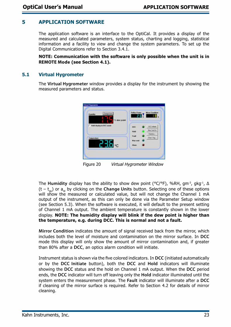
5.1 Virtual Hygrometer
The Virtual Hygrometer window provides a display for the instrument by showing the measured parameters and status.
Figure 20 Virtual Hygrometer Window
The Humidity display has the ability to show dew point (°C/°F), %RH, gm-3, gkg-1, ∆ (t – tdp) or aW by clicking on the Change Units button. Selecting one of these options will show the measured or calculated value, but will not change the Channel 1 mA output of the instrument, as this can only be done via the Parameter Setup window (see Section 5.3). When the software is executed, it will default to the present setting of Channel 1 mA output. The ambient temperature is constantly shown in the lower display. NOTE: The humidity display will blink if the dew point is higher than the temperature, e.g. during DCC. This is normal and not a fault.
Mirror Condition indicates the amount of signal received back from the mirror, which includes both the level of moisture and contamination on the mirror surface. In DCC mode this display will only show the amount of mirror contamination and, if greater than 80% after a DCC, an optics alarm condition will initiate.
Instrument status is shown via the five colored indicators. In DCC (initiated automatically or by the DCC Initiate button), both the DCC and Hold indicators will illuminate showing the DCC status and the hold on Channel 1 mA output. When the DCC period ends, the DCC indicator will turn off leaving only the Hold indicator illuminated until the system enters the measurement phase. The Fault indicator will illuminate after a DCC if cleaning of the mirror surface is required. Refer to Section 4.2 for details of mirror cleaning.
OptiCal User’s Manual
24 97079 Issue 9.2, March 2016
APPLICATION SOFTWARE
The Alarm indicator will illuminate when the measured variable exceeds the alarm set point (if selected) (refer to Section 5.3).
Max Cool can be initiated by the Max Cool On button. Once initiated, the Max Cool indicator will illuminate and the system will drive the heat pump into maximum depression. This feature can be used to ascertain if the measured dew point is within the measurement capability of the instrument.
Clicking on the Statistics button allows maximum, minimum and average values of the measured parameters to be viewed. See Section 5.5.
Charting and logging of the measured values can be initiated by clicking on the Chart/log button. See Section 5.4. The Hold display in DCC mode check box stops the system from updating the display during DCC, when enabled. The display is held when DCC is initiated and is not updated until both DCC and Hold periods have expired.
5.2 OptiCal Remote Chamber Control
The OptiCal chamber relative humidity and temperature set points can be controlled remotely from within OptiSoft. Refer to Section 3.4.
5.3 Parameter Setup
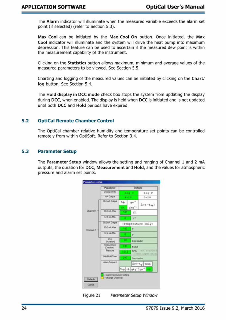
The Parameter Setup window allows the setting and ranging of Channel 1 and 2 mA outputs, the duration for DCC, Measurement and Hold, and the values for atmospheric pressure and alarm set points.
Figure 21 Parameter Setup Window
OptiCal User’s Manual
Kahn Instruments, Inc. 25
APPLICATION SOFTWARE
The Display Units and Channel 1 mA output are selected by clicking the left hand mouse button in the relevant box. This will change the settings of both the instrument and the virtual hygrometer window. Changing the mA outputs from 4-20 mA to 0-20 mA & vice versa will change both Channel 1 & Channel 2 mA outputs.
The maximum and minimum values of Channel 1 and Channel 2 are –200 to +1000 respectively, therefore allowing the range of the outputs to be anywhere between these limits. The values for Max and Min must be integer values with a difference between them of at least 1°C/F.
If Channel 1 is to be set for %RH, gm-3 , gkg-1, or ∆ (t – tdp), then the minimum value of Channel 1 Min should be 0, as a negative value for these parameters is not possible.
The pressure value is used to correct gm-3 and gkg-1 for atmospheric pressure. By entering the atmospheric pressure the display and Channel 1 mA output (if either gm-3 or gkg-1 is selected) will both be corrected accordingly.
The Alarm can be set to OFF or set to be active on any of the process variables i.e. dew point, ambient temperature, temperature difference, %RH, gm-3 or gkg-1 as shown above. The set point needs to be an integer value between –200 and +1000, although negative set points are only valid for dew point and ambient temperature. If the process variable exceeds the set point, the Alarm indicator on the virtual hygrometer will illuminate and the Optics Fault/Alarm relay will change state.
To change any of the values, enter the required value and click on the return key. The background of the text box will change to yellow to indicate that the change is taking place. When confirmation has been received that the instrument has accepted the change, the background will change back to green.
NOTE: When the Parameter Setup window is open, the values in the Virtual Hygrometer window are frozen. The Parameter Setup window needs to be closed for the software to resume normal display mode.
OptiCal User’s Manual
26 97079 Issue 9.2, March 2016
APPLICATION SOFTWARE
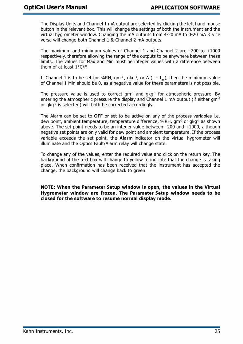
5.4 Charting and Logging
Clicking on the Chart/log button in the Virtual Hygrometer window brings up the Chart / log control panel window.
Figure 22 Chart/Log Control Panel Window
The chart, in its default configuration, displays dew point, temperature and %RH. However, gm-3, gkg-1 and ∆(t – tdp), can be added by clicking in the appropriate check box. Within the Global section, you can select the charting and logging interval from a minimum of 5 seconds to a maximum of 1 hour. It offers the facility to log the temperature of the mirror while in DCC and Hold, or hold the measured value while in these modes and chart the held data values accordingly.
To log the measured and calculated humidity values to a data file for further analysis, click on the check box in the Logging section and specify a file name by clicking on the Browse button. If a log file is not required simply uncheck the box.
To Run, Pause and Stop the charting and logging facility, use the chart control buttons accordingly.
OptiCal User’s Manual
Kahn Instruments, Inc. 27
APPLICATION SOFTWARE
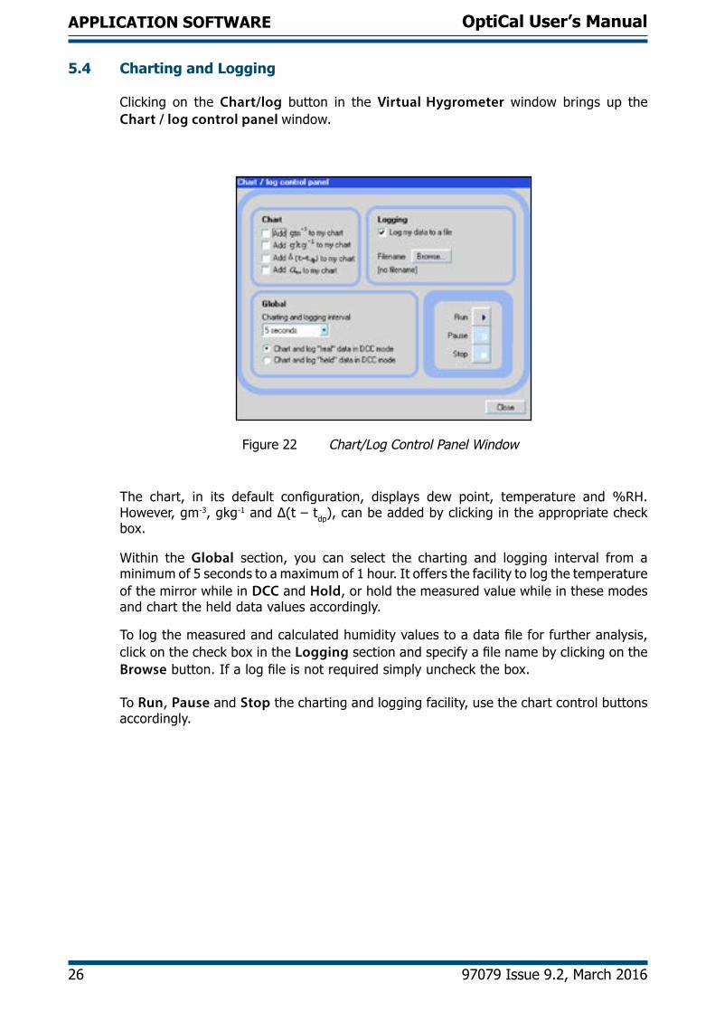
Clicking on the Run button will bring up the chart as shown below. The chart shows the measured and calculated humidity values selected in the Chart section, with an assigned identifiable color for each value. It is possible to scale, zoom and scroll both X and Y axis of the chart by using the controls in the Chart Settings window, which can be activated by clicking on the Chart Settings button.
Figure 23 Chart Window
The X & Y axes can be individually scaled. The X-axis can be scaled by using the ZoomX feature in the Chart mode section, while the Y-axis can be scaled by changing the min and max values, or selecting a parameter in the Auto-scale list, which scales the Y-axis to the actual values of the parameter.
There are a number of modes associated with the chart, which can be selected from the Chart mode list; Plot, Scroll (X, Y, & XY), Cursor, Zoom (X, Y, & XY) and Zoom Box. In order to use the scrolling and zooming modes, make your selection and click the left mouse button on the chart itself, moving the mouse across the chart accordingly with the left mouse button held down. This will zoom or scroll the chart accordingly.
Individual data points can be selected from the chart by using the cursor mode. Select the parameter in question by clicking on a legend on the right hand side of the chart (°C dew point is shown as selected above) and moving the cursor to the point of interest - the actual value with its time stamp will be displayed above the chart.
OptiCal User’s Manual
28 97079 Issue 9.2, March 2016
APPLICATION SOFTWARE
5.5 Statistics
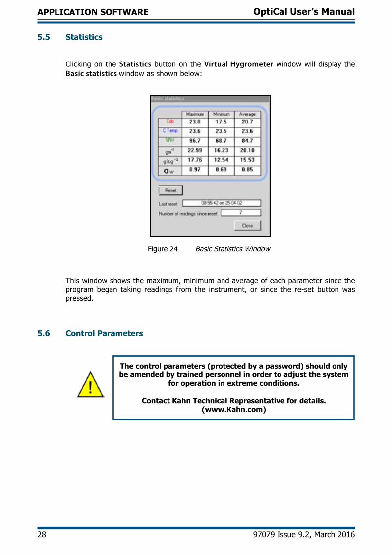
Clicking on the Statistics button on the Virtual Hygrometer window will display the Basic statistics window as shown below:
Figure 24 Basic Statistics Window
This window shows the maximum, minimum and average of each parameter since the program began taking readings from the instrument, or since the re-set button was pressed.
5.6 Control Parameters
The control parameters (protected by a password) should only be amended by trained personnel in order to adjust the system
for operation in extreme conditions.
Contact Kahn Technical Representative for details. (www.Kahn.com)
OptiCal User’s Manual
Kahn Instruments, Inc. 29
APPLICATION SOFTWARE
5.7 Calibration Correction
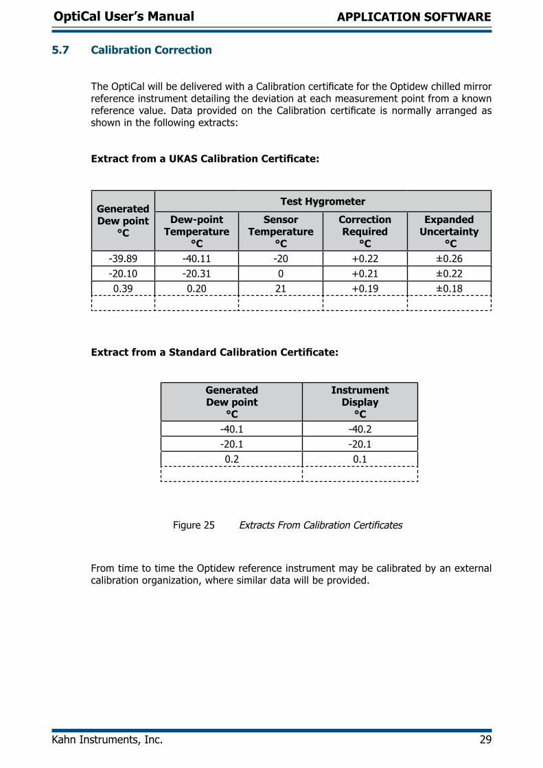
The OptiCal will be delivered with a Calibration certificate for the Optidew chilled mirror reference instrument detailing the deviation at each measurement point from a known reference value. Data provided on the Calibration certificate is normally arranged as shown in the following extracts:
Extract from a UKAS Calibration Certificate:
GeneratedDew point
°C
Test Hygrometer
Dew-pointTemperature
°C
Sensor Temperature
°C
CorrectionRequired
°C
ExpandedUncertainty
°C-39.89 -40.11 -20 +0.22 ±0.26-20.10 -20.31 0 +0.21 ±0.220.39 0.20 21 +0.19 ±0.18
Extract from a Standard Calibration Certificate:
Generated Dew point
°C
InstrumentDisplay
°C-40.1 -40.2-20.1 -20.10.2 0.1
Figure 25 Extracts From Calibration Certificates
From time to time the Optidew reference instrument may be calibrated by an external calibration organization, where similar data will be provided.
OptiCal User’s Manual
30 97079 Issue 9.2, March 2016
APPLICATION SOFTWARE
The Calibration Correction window is a utility that allows an authorized user to input calibration information in order to effect a real-time correction of the displayed, charted and logged data within the Opti-Soft application software.
Data for dew-point temperature and ambient temperature, both in units of °C, may be entered for correction purposes, along with the original Calibration certificate reference number and date of calibration, providing full traceability of data. Once the correction data has been applied, by clicking on the check box, the main Virtual Hygrometer window will indicate that corrected data is being displayed and will show the Calibration certificate number and date. This information is also saved to the Log file for data export.
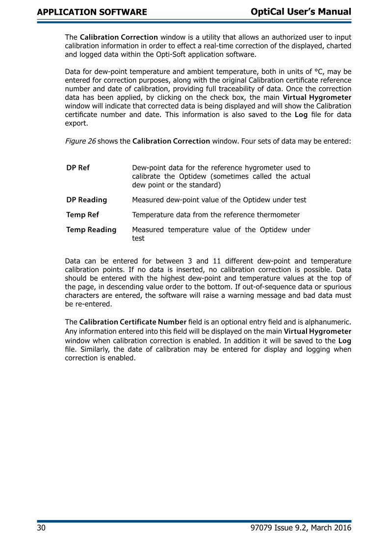
Figure 26 shows the Calibration Correction window. Four sets of data may be entered:
DP Ref Dew-point data for the reference hygrometer used to calibrate the Optidew (sometimes called the actual dew point or the standard)
DP Reading Measured dew-point value of the Optidew under test
Temp Ref Temperature data from the reference thermometer
Temp Reading Measured temperature value of the Optidew under test
Data can be entered for between 3 and 11 different dew-point and temperature calibration points. If no data is inserted, no calibration correction is possible. Data should be entered with the highest dew-point and temperature values at the top of the page, in descending value order to the bottom. If out-of-sequence data or spurious characters are entered, the software will raise a warning message and bad data must be re-entered.
The Calibration Certificate Number field is an optional entry field and is alphanumeric. Any information entered into this field will be displayed on the main Virtual Hygrometer window when calibration correction is enabled. In addition it will be saved to the Log file. Similarly, the date of calibration may be entered for display and logging when correction is enabled.
OptiCal User’s Manual
Kahn Instruments, Inc. 31
APPLICATION SOFTWARE
Once all necessary data has been entered in the Calibration Correction window, click on the Use Calibration Date to Correct Measure Values check box and then click on Apply and Close to return to the main Virtual Hygrometer display. Upon the next update, the corrections entered will be applied to all displayed and logged data, and a legend above the display will indicate this fact. To remove Calibration Correction, de-select the check box and click on Apply, then on Close.
Figure 26 Calibration Correction Window
NOTE: Enter the calibration data in descending order so the highest values are in row 1 as shown above.
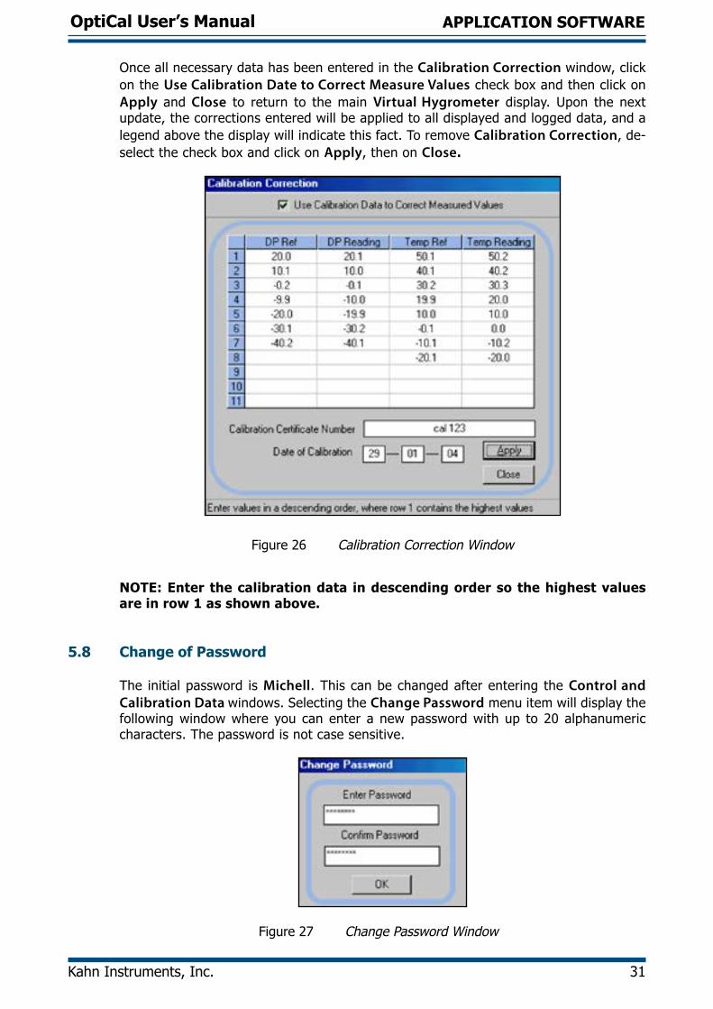
5.8 Change of Password
The initial password is Michell. This can be changed after entering the Control and Calibration Data windows. Selecting the Change Password menu item will display the following window where you can enter a new password with up to 20 alphanumeric characters. The password is not case sensitive.
Figure 27 Change Password Window
OptiCal User’s Manual
32 97079 Issue 9.2, March 2016
TROUBLESHOOTING
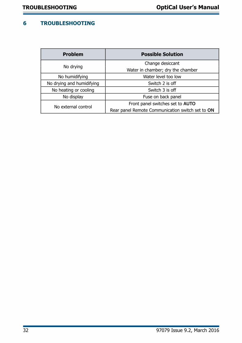
6 TROUBLESHOOTING
Problem Possible Solution
No dryingChange desiccant
Water in chamber; dry the chamberNo humidifying Water level too low
No drying and humidifying Switch 2 is offNo heating or cooling Switch 3 is off
No display Fuse on back panel
No external controlFront panel switches set to AUTO
Rear panel Remote Communication switch set to ON

OptiCal User’s Manual
Kahn Instruments, Inc. 33
APPENDIX A
Appendix A
Technical Specifications
OptiCal User’s Manual
34 97079 Issue 9.2, March 2016
APPENDIX A
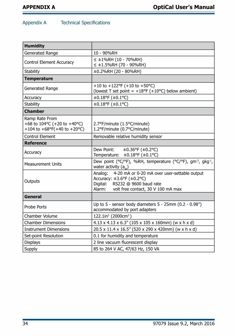
Appendix A Technical Specifications
Humidity
Generated Range 10 - 90%RH
Control Element Accuracy ≤ ±1%RH (10 - 70%RH)≤ ±1.5%RH (70 - 90%RH)
Stability ±0.2%RH (20 - 80%RH)
Temperature
Generated Range +10 to +122°F (+10 to +50°C)(lowest T set point = +18°F (+10°C) below ambient)
Accuracy ±0.18°F (±0.1°C)Stability ±0.18°F (±0.1°C)
Chamber
Ramp Rate From +68 to 104°C (+20 to +40°C)+104 to +68°F(+40 to +20°C)
2.7°F/minute (1.5°C/minute)1.2°F/minute (0.7°C/minute)
Control Element Removable relative humidity sensorReference
Accuracy Dew Point: ±0.36°F (±0.2°C)Temperature: ±0.18°F (±0.1°C)
Measurement Units Dew point (°C/°F), %RH, temperature (°C/°F), gm-3, gkg-1, water activity (aW)
Outputs
Analog: 4-20 mA or 0-20 mA over user-settable outputAccuracy: ±3.6°F (±0.2°C) Digital: RS232 @ 9600 baud rateAlarm: volt free contact, 30 V 100 mA max
General
Probe Ports Up to 5 - sensor body diameters 5 - 25mm (0.2 - 0.98”)accommodated by port adapters
Chamber Volume 122.1in3 (2000cm3 )Chamber Dimensions 4.13 x 4.13 x 6.3” (105 x 105 x 160mm) (w x h x d)Instrument Dimensions 20.5 x 11.4 x 16.5” (520 x 290 x 420mm) (w x h x d)Set-point Resolution 0.1 for humidity and temperatureDisplays 2 line vacuum fluorescent displaySupply 85 to 264 V AC, 47/63 Hz, 150 VA
OptiCal User’s Manual
Kahn Instruments, Inc. 35
APPENDIX B
Appendix B
EC Declaration of Conformity

OptiCal User’s Manual
36 97079 Issue 9.2, March 2016
APPENDIX B
Appendix B EU Declaration of Conformity