Embed Size (px)
Citation preview

Optical Alignment System for Muon Tracker
1. Hardware
2. Learned from RUN3/4
3. Upgrade
4. Plan and Summary
Atsushi Taketani,
RIKEN/RIKEN Brookhaven Research Center
Hiroki Kanou, Takashi Watanabe, Nobuyuki Kamihara, and Takuma Horaguchi
Tokyo Institute of Technology

Optical Alignment Sytem
Total 7optics/Octant * 8 Octant/Arm * 2Arm = 112
Configuration
Light Source( station1) ・ Single 150W Halogen light per
・ Optical fiber to station1
Focusing lens(station2) ・ 1cm convex lens
CCD camera (station3)•effective area 8.8×6.6 mm•Number of pixels 768× 498•Pixel size 11.0×13.0 m
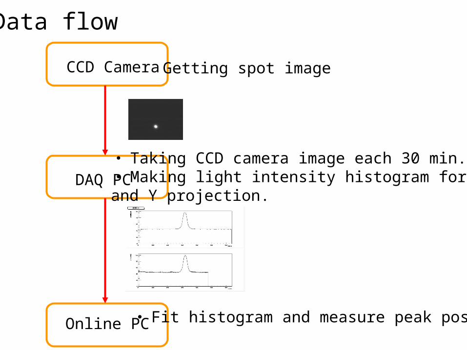
Data flow
CCD Camera
DAQ PC
Online PC
・ Taking CCD camera image each 30 min.・Making light intensity histogram for each X and Y projection.
・ Fit histogram and measure peak position
Getting spot image
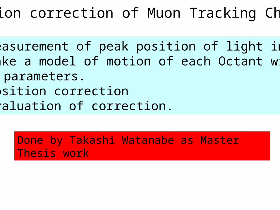
Position correction of Muon Tracking Chamber
1.Measurement of peak position of light image.2.Make a model of motion of each Octant with parameters.3. Position correction4. Evaluation of correction.
Done by Takashi Watanabe as Master Thesis work

Measurement of peak psotionSharp image Out focus Image
gauss fit window fit pixelpixel
Bri
ghtn
ess
Bri
ghtn
ess
X projection
Y projection
X projection
Y projection
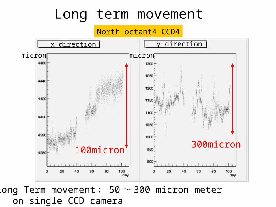
Long term movement
Long Term movement: 50~ 300 micron meter on single CCD camera
100micron300micron
x direction y direction
micron micron
North octant4 CCD4

Movement Model without expansion
Consider half octant as rigid body
( ) xi - z yi + X z xi + yi + Y
~ Model of movement
x0i + xi
y0i + yi= ( ) xi : Image position
S = Sum | fi - xi | 2
= Sum{( - z y0i + X - xi)2 + (z x0i + Y - yi)2
Minimize S with rotation and displacement
Rotation
Displacement in PHENIX
Position on Octant
Look at the movement on X and Y
Ignore rotation along X and Y axis
( ) ( ) ( ) xi
yi
zi
XYZ
+ fi = Rot ( x, y,z )
Center of gravity of camera on octant
Peak position
in camera
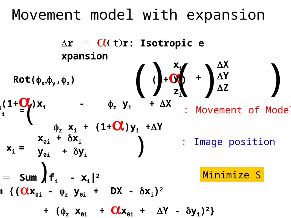
Movement model with expansion
r = tr: Isotropic expansion
( ) ( )( ) fi = Rot(xy,z) (1+)
xi
yi
zi
XYZ
( )(1+)xi - z yi +X
z xi + (1+)yi +Y
fi = :Movement of Model
( ) xi = x0i + xi
y0i + yi
: Image position
S = Sum |fi - xi|2
= Sum {(x0i - z y0i + DX - xi)2
+ (z x0i + x0i + Y - yi)2}
Minimize S

Camera Combination
Combination
CCD4 CCD5 CCD6 CCD7
456 ○ ○ ○
457 ○ ○ ○
467 ○ ○ ○
567 ○ ○ ○
・ Use North Arm, octant4, CCD4、 5、 6、 7・ Evaluate by comparing different camera configuration

0
0
10- 10
- 10
10
10
micron
micron
micron
456 and 457
Correction comparison onx456 and 467
456 and 5670- 10
Correction evaluation Displacement on X : 9~ 27 micron Y : 5~ 24 micron Rotation along Z axis : 4- 15 micro rad Expansion : 2 ~ 15* 10^-6

Temperature andMagnetic field dependence
・ Temperature changes after magnetic field change
・Magnetic field moves chamber
day
day
day
day
day
day
C
mm
mm
rad
Magnetic field
Temp
X
Y
z

RUN4Rate of Operation
0
20
40
60
80
100
0 5 10 15
Month
Rate
of O
prat
ion NorthSouth
North South
Good 24 12
Recoverable 16 23
No Image 16 21
Data acquisition is not stable.
Pay attention by MuTr expert shift or
PHENIX shift.
Good: good accuracy of peak
Recoverable : not good accuracy
No Image : No image at all

How to Improve
• No Image : Need to access the area inside magnet. -> Not this year.
• Recoverable: Take more picture, integrate them and then get sharper image.
• Replace DAQ system from GUI operation base to Labview base.

Windows GPIB-Ether Net MultiplexerCCD Camera
(*56)
Video signal
LAN
GPIB
Video signal
LAN
Linux
Change camerasTake pictures,IntegrationMake projectionSave data
Daq system
Video Capture board
Labview

Initialize system few msecCheck hardware few secChange camera 50 msec for 1chTake pictures 110 msec for 1ch, 1 pictureIntegrate pictures 40 msec for 1ch, 1 pictureMake projection 40 msec for 1chSave to file 20 msec for 1chClose system few msec
Large contribution
Executed56 times
Take N pictures for all camera…
T = 8.09N + 5.06 + few (sec)
(N < 73, T < 10 min.)
All of components for prototyping are build at RIKEN

Plan and Summary
• Young Hiroki will build Labview based system at RIKEN and move it to BNL at Aug.
• Looking OASYS will be shift duty.
• OASYS analysis data will be implemented in the geometry database and then improve J/PSI mass resolution.
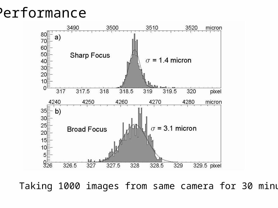
Performance
Taking 1000 images from same camera for 30 minutes.
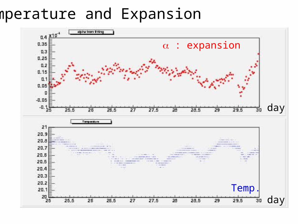
Temperature and Expansion
day
day
: expansion
Temp.


![CAS1007 AD-[FlWeekly]_Fulpg[run3-19-15]](https://img.pdfslide.net/doc/110x75/58aa3e801a28ab4c348b4f13/cas1007-ad-flweeklyfulpgrun3-19-15.jpg)