Embed Size (px)
DESCRIPTION
laser modes and optical cavity
Citation preview
Optical Cavity and laser Modes

Conditions Which Determine The Radiation Modes Created In Common Lasers
1. standing waves
2. The properties of the optical signal
3. longitudinal modes
4. The transverse modes
5. The common optical cavities
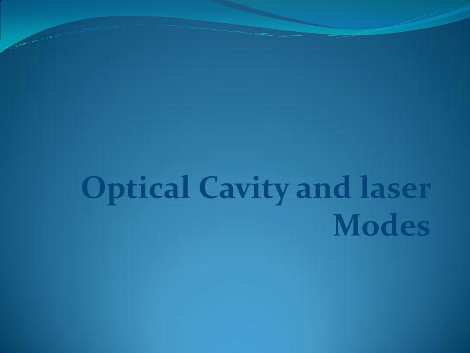
The solid line describes a wavemoving to the left. On the right side of figurethe superposition of the two waves is shown. Like a standing wave in a stringattached to fixed points at both sides, the fixed points of a standing wave are called Nodes. The distance between adjacentNodes is half the wavelengthof each of the interfering waves
Creating standing wave from two waves moving in opposite directions
Optical cavity is created two mirrors at both ends of the laser.Laser mirrors serve two goals: 1.Increase the length of the active medium, by making the beam pass through it many times. 2.Determine the boundary conditions for the electromagnetic fields inside the laser cavity. Fabry – Perot resonator :is a cavity with two mirrors
Optical Axis of the laser: the laser beam is ejected out of the laser in the direction of the optical axis.
Standing Waves In A Laser
First, What are standing waves. •What are the conditions for creating standing waves. •How standing waves in a laser cavity are determined by the laser design. Second, the properties of the optical signal which is amplified while passing back and force through the active medium are discussed. Third, longitudinal modes are created in the laser cavity.Their importance and methods for controlling them. Forth, the distribution of energy along the cross section of the beam, which determine the transverse modes. At the end describing the common optical cavitiesand the way to test their stability.

Two waves of the same frequency and
amplitude are moving in opposite directions,
which is the condition for creating a standing
wave.
Remember that the electromagnetic waves
inside the laser cavity are 3 dimensional, and are
moving along the optical axis of the laser.

•The optical path from one mirror to the other and back must be
an integer multiplication of the wavelength.
•The wave must start with the same phase at the mirror
•The Length between the mirrors is constant (L), the suitable
wavelengths, which create standing waves, must fulfill the
condition: lm = 2L/m
L = Length of the optical cavity.
m = Number of the mode, which is equal to the number of half
wavelengths inside the optical cavity
lm = Wavelength of mode m inside the laser cavity.
Wavelength in matter (lm) is equal to: lm = l0/n
l0 = Wavelength of light in vacuum.
n = Index of refraction of the active medium.
c = Velocity of light in vacuum.
Create A Standing Wave
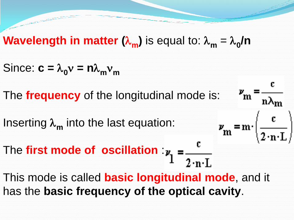
Wavelength in matter (lm) is equal to: lm = l0/n
Since: c = l0n = nlmnm
The frequency of the longitudinal mode is:
Inserting lm into the last equation:
The first mode of oscillation :
This mode is called basic longitudinal mode, and it
has the basic frequency of the optical cavity.
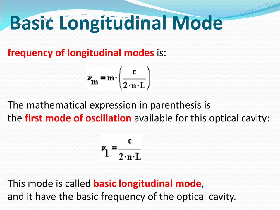
frequency of longitudinal modes is:
The mathematical expression in parenthesis is the first mode of oscillation available for this optical cavity:
This mode is called basic longitudinal mode, and it have the basic frequency of the optical cavity.
Basic Longitudinal Mode
Conclusion:The frequency of each laser mode is equal to integer (mode number m) times the frequency of the basic longitudinal mode.From this conclusion it is immediately seen thatThe difference between frequencies of adjacent modes (mode spacing) is equal to the basic frequency of the cavity: (Δn) = c/(2nL)
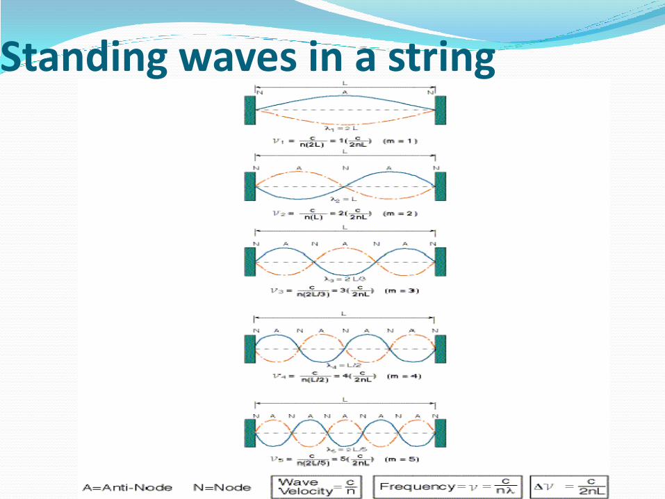
Standing waves in a string
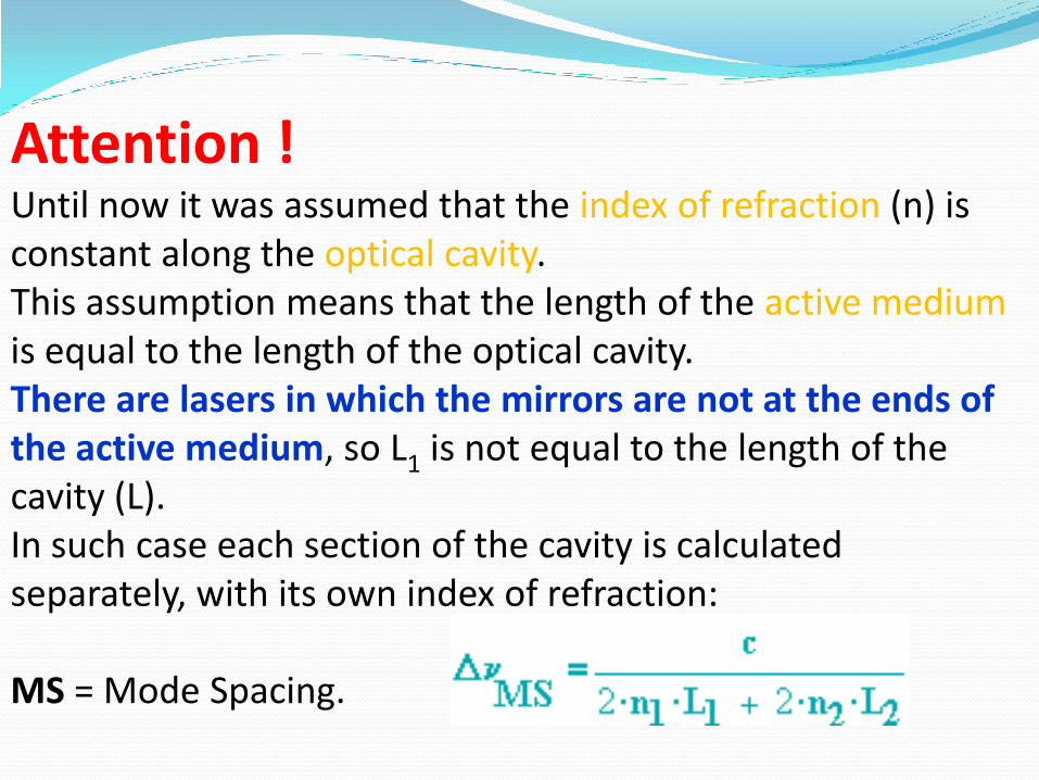
Attention !Until now it was assumed that the index of refraction (n) is constant along the optical cavity. This assumption means that the length of the active medium is equal to the length of the optical cavity. There are lasers in which the mirrors are not at the ends of the active medium, so L1 is not equal to the length of the cavity (L). In such case each section of the cavity is calculated separately, with its own index of refraction:
MS = Mode Spacing.

Question The length of the optical cavity of a Nd-
YAG laser is 30 [cm].
The length of the laser rod which makes the
active medium is 10 [cm]. The index of
refraction of the laser rod is 1.823.
The rest of the cavity is air which have an index
of refraction of 1.0.
Calculate the difference in frequencies between
adjacent modes.

Example 1 : Frequencies and wavelengths of possible modes in an optical cavityThe length of an optical cavity is 25 [cm]. The index of refraction is 1.0. Calculate the frequencies nm and wavelengths lm of the following modes: m =1. m = 10. m = 100. m = 106.
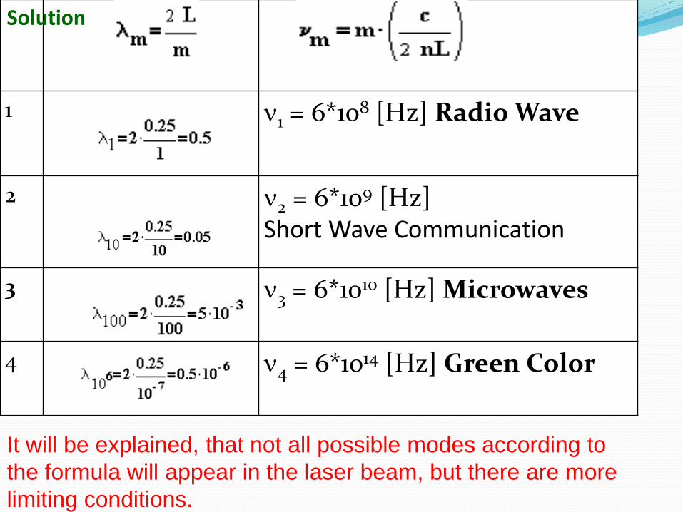
1 n1 = 6*108 [Hz] Radio Wave
2 n2 = 6*109 [Hz] Short Wave Communication
3 n3 = 6*1010 [Hz] Microwaves
4 n4 = 6*1014 [Hz] Green Color
Solution
It will be explained, that not all possible modes according to
the formula will appear in the laser beam, but there are more
limiting conditions.
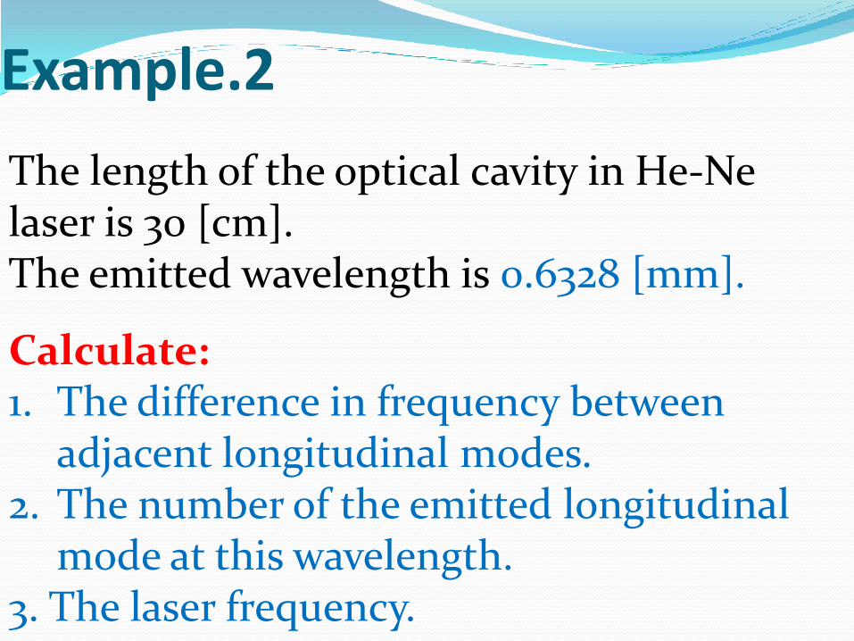
The length of the optical cavity in He-Ne laser is 30 [cm]. The emitted wavelength is 0.6328 [mm].
Calculate:1. The difference in frequency between
adjacent longitudinal modes. 2. The number of the emitted longitudinal
mode at this wavelength.3. The laser frequency.
Example.2
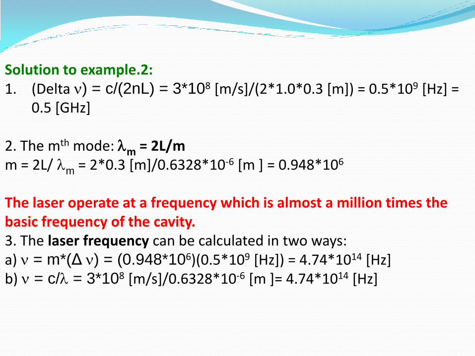
Solution to example.2:1. (Delta n) = c/(2nL) = 3*108 [m/s]/(2*1.0*0.3 [m]) = 0.5*109 [Hz] =
0.5 [GHz]
2. The mth mode: lm = 2L/mm = 2L/ lm = 2*0.3 [m]/0.6328*10-6 [m ] = 0.948*106
The laser operate at a frequency which is almost a million times the basic frequency of the cavity.3. The laser frequency can be calculated in two ways:a) n = m*(Δ n) = (0.948*106)(0.5*109 [Hz]) = 4.74*1014 [Hz]b) n = c/l = 3*108 [m/s]/0.6328*10-6 [m ]= 4.74*1014 [Hz]

In practice, the frequencies are not defined mathematically as single frequencies, but each have a width of frequencies around the possible modes,
Allowed Longitudinal modes inside a Laser Cavity of length (L) and index of refraction (n).
Allowed Frequencies inside a Laser Cavity
Longitudinal modes are standing waves along the
optical axis of the laser.
The standing waves inside a laser are created when
the electromagnetic radiation is forced to move back into
the cavity from the mirrors.
The allowed frequencies inside an optical cavity are
determined by the length of the cavity (L) and the
index of refraction of the active medium.
Only those frequencies which create nodes at both
mirrors are allowed. Thus, the cavity length must be an
integer multiplication of half their wavelengths.
The allowed frequencies are spaced at constant
interval, which is equal to the basic frequency of the
cavity.
Longitudinal Modes in a Laser explains that only
specific frequencies are possible inside the optical
cavity of a laser, according to standing wave
condition.
From all these possible frequencies, only those that
have amplification above certain minimum, to
overcome, will be emitted out of the laser.
This minimum amplification is defined as lasing
threshold.
The condition of minimum amplification means that
the amplification is equal to losses, so that in a round
trip path inside the cavity GL = 1.

The height of each lasing line depends on the losses in a round trip inside the cavity, including the emitted radiation through the output coupler.
The marked region under the curve and above the lasing threshold include the range where lasing can occur.
The height of the gain curve depend on the length of the active medium and its excitation.
The possible longitudinal modes of the laser are marked as perpendicular lines at equal distances from each other. Only frequencies from those allowed inside the cavity, are above the lasing threshold.
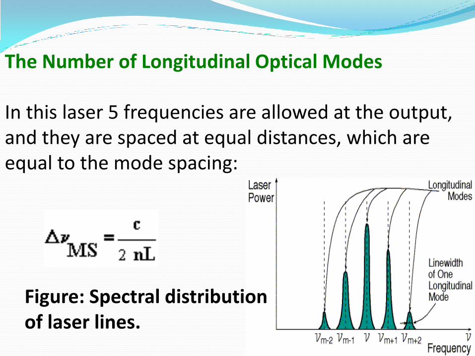
The Number of Longitudinal Optical Modes
In this laser 5 frequencies are allowed at the output, and they are spaced at equal distances, which are equal to the mode spacing:
Figure: Spectral distribution of laser lines.
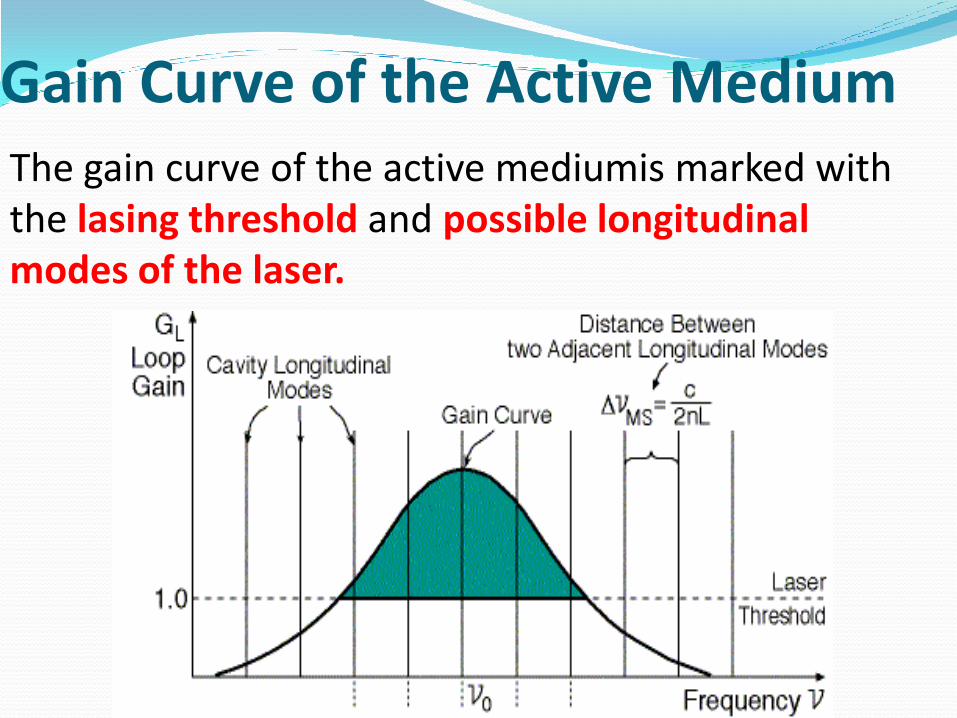
The gain curve of the active mediumis marked with the lasing threshold and possible longitudinal modes of the laser.
Gain Curve of the Active Medium
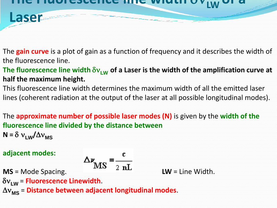
The gain curve is a plot of gain as a function of frequency and it describes the width of the fluorescence line. The fluorescence line width dnLW of a Laser is the width of the amplification curve at half the maximum height.This fluorescence line width determines the maximum width of all the emitted laser lines (coherent radiation at the output of the laser at all possible longitudinal modes).
The approximate number of possible laser modes (N) is given by the width of the fluorescence line divided by the distance between N = d nLW/DnMS
adjacent modes:
MS = Mode Spacing. LW = Line Width. dnLW = Fluorescence Linewidth. DnMS = Distance between adjacent longitudinal modes.
The Fluorescence line width dnLW of a Laser
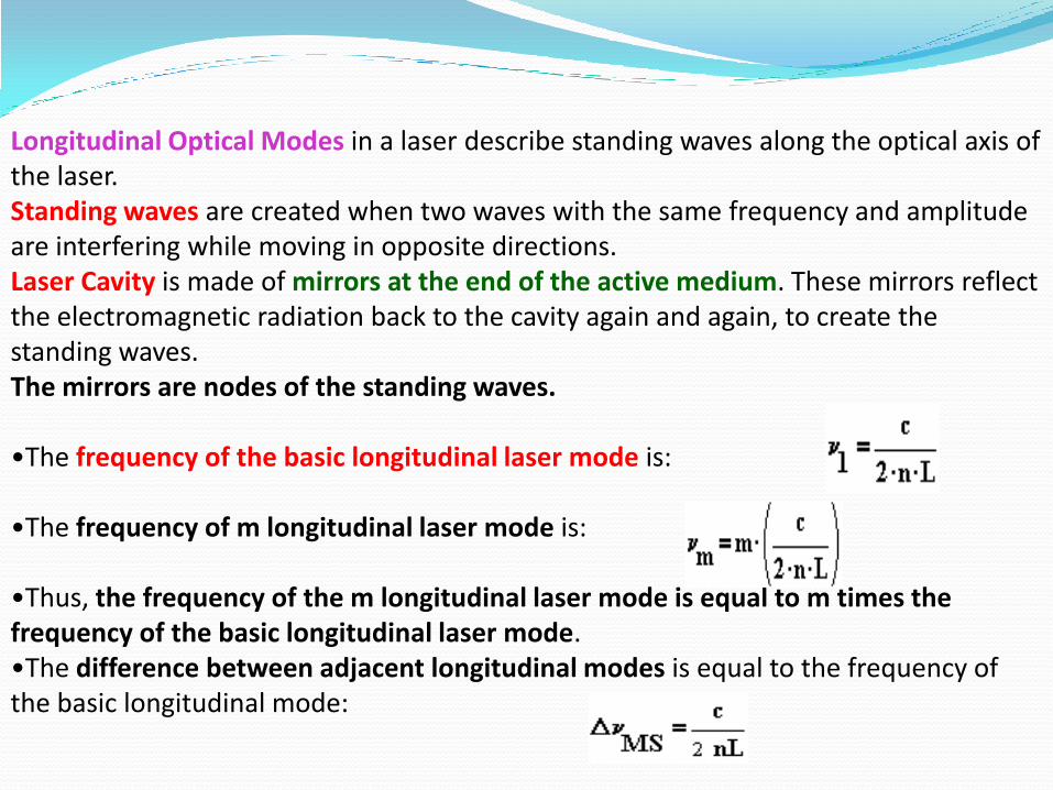
Longitudinal Optical Modes in a laser describe standing waves along the optical axis of the laser. Standing waves are created when two waves with the same frequency and amplitude are interfering while moving in opposite directions. Laser Cavity is made of mirrors at the end of the active medium. These mirrors reflect the electromagnetic radiation back to the cavity again and again, to create the standing waves. The mirrors are nodes of the standing waves.
•The frequency of the basic longitudinal laser mode is:
•The frequency of m longitudinal laser mode is:
•Thus, the frequency of the m longitudinal laser mode is equal to m times the frequency of the basic longitudinal laser mode. •The difference between adjacent longitudinal modes is equal to the frequency of the basic longitudinal mode:
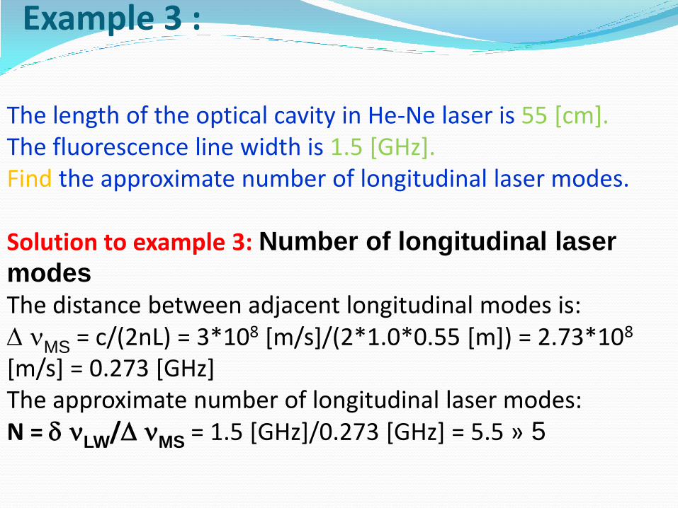
The length of the optical cavity in He-Ne laser is 55 [cm]. The fluorescence line width is 1.5 [GHz]. Find the approximate number of longitudinal laser modes.
Solution to example 3: Number of longitudinal laser
modes
The distance between adjacent longitudinal modes is: D nMS = c/(2nL) = 3*108 [m/s]/(2*1.0*0.55 [m]) = 2.73*108
[m/s] = 0.273 [GHz]The approximate number of longitudinal laser modes: N = d nLW/D nMS = 1.5 [GHz]/0.273 [GHz] = 5.5 » 5
Example 3 :
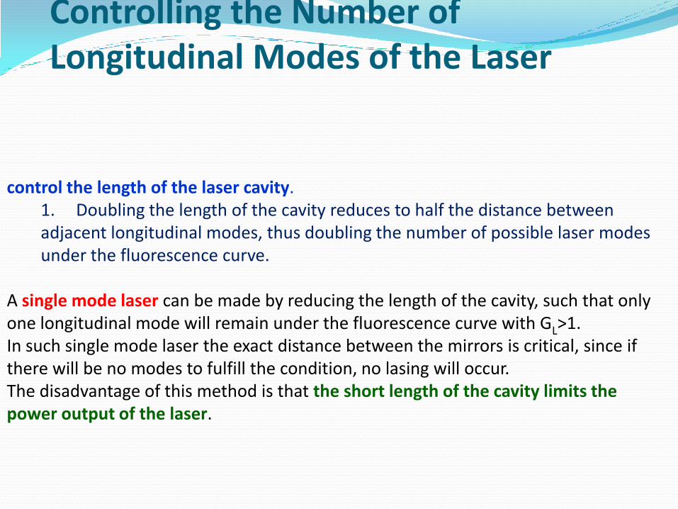
control the length of the laser cavity. 1. Doubling the length of the cavity reduces to half the distance between adjacent longitudinal modes, thus doubling the number of possible laser modes under the fluorescence curve.
A single mode laser can be made by reducing the length of the cavity, such that only one longitudinal mode will remain under the fluorescence curve with GL>1. In such single mode laser the exact distance between the mirrors is critical, since if there will be no modes to fulfill the condition, no lasing will occur. The disadvantage of this method is that the short length of the cavity limits the power output of the laser.
Controlling the Number of Longitudinal Modes of the Laser
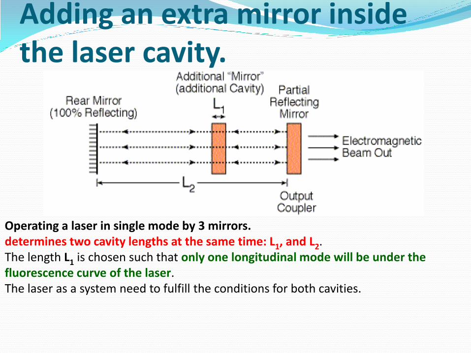
Operating a laser in single mode by 3 mirrors.determines two cavity lengths at the same time: L1, and L2. The length L1 is chosen such that only one longitudinal mode will be under the fluorescence curve of the laser. The laser as a system need to fulfill the conditions for both cavities.
Adding an extra mirror inside the laser cavity.
Are modes in cross section of the beam, perpendicular to the optical axis of the laser.
These transverse modes are created by the width of the cavity, which enables a few diagonal modes to develop inside the laser cavity.
A little misalignment of the laser mirrors causes different path length for different rays inside the cavity.
The transverse distribution of intensity
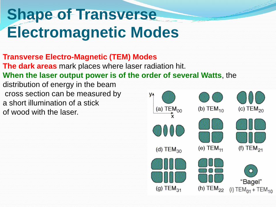
Transverse Electro-Magnetic (TEM) Modes
The dark areas mark places where laser radiation hit.
When the laser output power is of the order of several Watts, the
distribution of energy in the beam
cross section can be measured by
a short illumination of a stick
of wood with the laser.
Shape of Transverse
Electromagnetic Modes
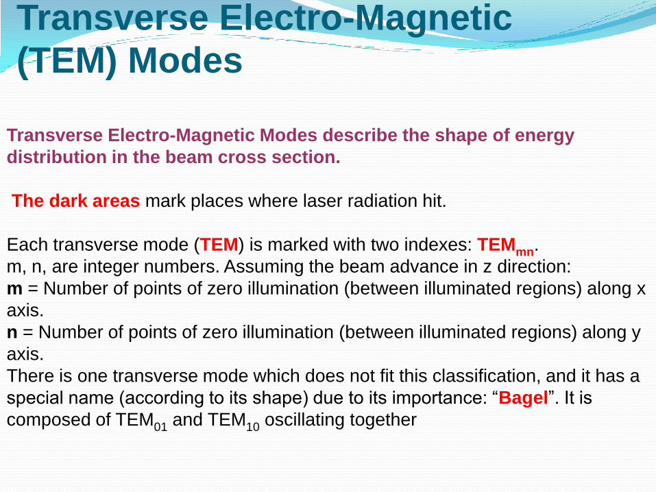
Transverse Electro-Magnetic Modes describe the shape of energy
distribution in the beam cross section.
The dark areas mark places where laser radiation hit.
Each transverse mode (TEM) is marked with two indexes: TEMmn.
m, n, are integer numbers. Assuming the beam advance in z direction:
m = Number of points of zero illumination (between illuminated regions) along x
axis.
n = Number of points of zero illumination (between illuminated regions) along y
axis.
There is one transverse mode which does not fit this classification, and it has a
special name (according to its shape) due to its importance: “Bagel”. It is
composed of TEM01 and TEM10 oscillating together
Transverse Electro-Magnetic
(TEM) Modes
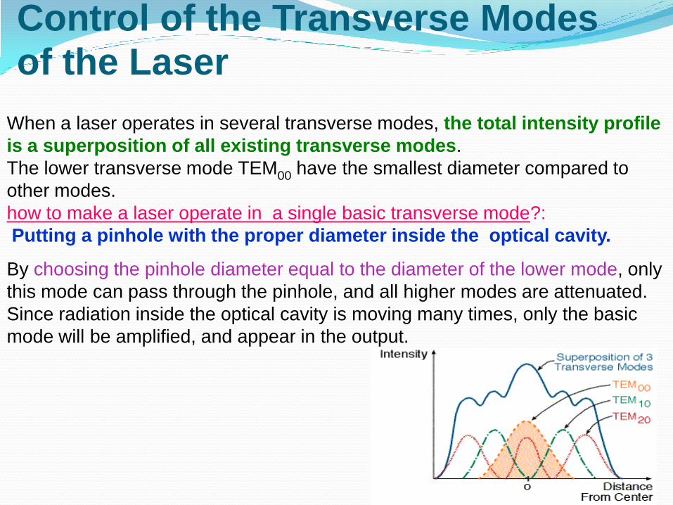
When a laser operates in several transverse modes, the total intensity profile
is a superposition of all existing transverse modes.
The lower transverse mode TEM00 have the smallest diameter compared to
other modes.
how to make a laser operate in a single basic transverse mode?:
Putting a pinhole with the proper diameter inside the optical cavity.
By choosing the pinhole diameter equal to the diameter of the lower mode, only
this mode can pass through the pinhole, and all higher modes are attenuated.
Since radiation inside the optical cavity is moving many times, only the basic
mode will be amplified, and appear in the output.
Control of the Transverse Modes
of the Laser
verses all other transverse modes.
1.Can be focused to the smallest spot than all other
transverse modes.
2.Have the maximum Spatial Coherence compared to
other transverse modes.
3.The spatial distribution of a Gaussian beam remains
Gaussian while the beam propagate through space.
Properties of Basic Gaussian Transverse Mode Lowest divergence angle
There are different shapes of mirrors, with different lengths between them. A specific optical cavity is determined by the active medium used, the optical power in it, and the specific application.The explanation here will summarize the design principles of an optical cavity:
Losses inside optical cavity. Common optical cavities. Stability criterion of laser optical cavity .
Optical Cavity In every laser cavity
Optical Cavity - Laser Cavity - The region between the end mirrors of the
laser.
Optical Axis -The imaginary line connecting the centers of the end
mirrors, and perpendicular to them. The optical axis is in the middle of the
optical cavity.
Aperture -The beam diameter limiting factor inside the laser cavity.
Usually the aperture is determined by the diameter of the active medium, but
in some lasers a pinhole is inserted into the laser cavity to limit the diameter
of the beam. An example is the limiting aperture for achieving single mode
operation of the laser
Losses inside Optical Cavity - Include all the radiation missing from the
output of the laser (emitted through the output coupler).
The gain of the active medium must overcome these losses
Losses inside an optical cavity Misalignment of the laser
mirrors –
• The cavity mirrors are not exactly aligned perpendicular to
the laser axis, and parallel to each other (symmetric), the
radiation inside the cavity will not be confined during its path
between the mirrors.
• Absorption, scattering and losses in optical elements -
Since optical elements are not ideal, each interaction with optical
element inside the cavity cause some losses.
• Diffraction Losses - Every time a laser beam pass through a
limiting aperture it diffract. It is not always possible to increase
the aperture for reducing the diffraction. As an example, such
increase will allow lasing in higher transverse modes which are
not desired

The most common
optical cavities
The dark region in each of the optical cavities mark
the volume of the active mode in this specific cavity.
Regions inside the active medium which are not
included inside the volume of the active mode do
not participate in lasing.
Two parameters determine the structure of the
optical cavity:
•The volume of the laser mode inside the active medium.
•The stability of the optical cavity.
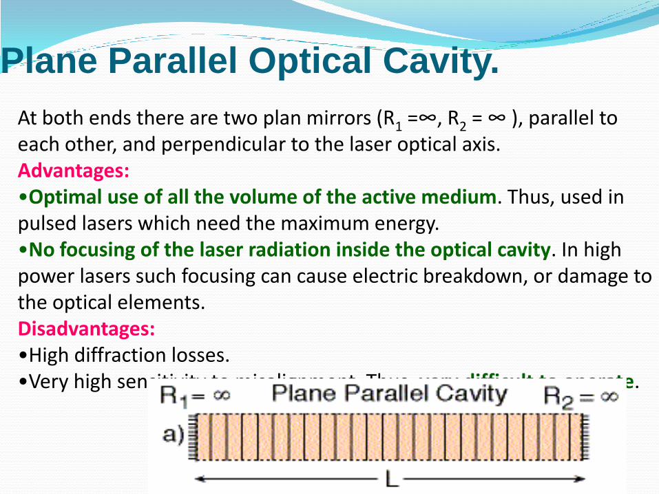
At both ends there are two plan mirrors (R1 =∞, R2 = ∞ ), parallel to each other, and perpendicular to the laser optical axis. Advantages:•Optimal use of all the volume of the active medium. Thus, used in pulsed lasers which need the maximum energy. •No focusing of the laser radiation inside the optical cavity. In high power lasers such focusing can cause electric breakdown, or damage to the optical elements. Disadvantages:•High diffraction losses. •Very high sensitivity to misalignment. Thus, very difficult to operate.
Plane Parallel Optical Cavity.
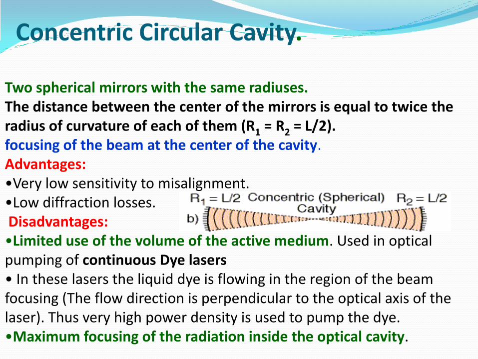
Two spherical mirrors with the same radiuses.The distance between the center of the mirrors is equal to twice the radius of curvature of each of them (R1 = R2 = L/2).focusing of the beam at the center of the cavity. Advantages:•Very low sensitivity to misalignment. •Low diffraction losses. Disadvantages:•Limited use of the volume of the active medium. Used in optical pumping of continuous Dye lasers• In these lasers the liquid dye is flowing in the region of the beam focusing (The flow direction is perpendicular to the optical axis of the laser). Thus very high power density is used to pump the dye. •Maximum focusing of the radiation inside the optical cavity.
Concentric Circular Cavity.
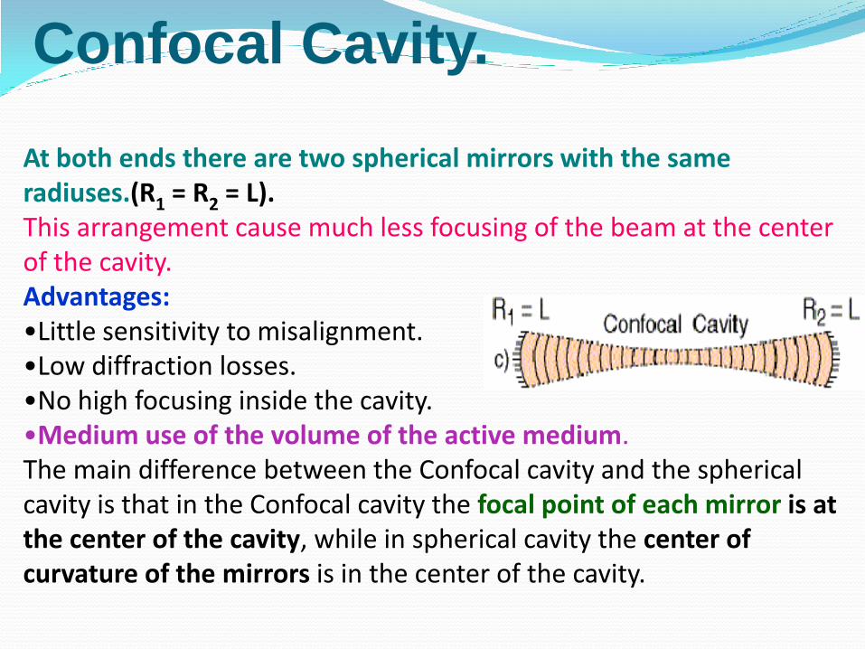
At both ends there are two spherical mirrors with the same radiuses.(R1 = R2 = L).This arrangement cause much less focusing of the beam at the center of the cavity.Advantages:•Little sensitivity to misalignment. •Low diffraction losses. •No high focusing inside the cavity. •Medium use of the volume of the active medium. The main difference between the Confocal cavity and the spherical cavity is that in the Confocal cavity the focal point of each mirror is at the center of the cavity, while in spherical cavity the center of curvature of the mirrors is in the center of the cavity.
Confocal Cavity.

This cavity is a better compromise than Confocal cavity between plan parallel and circular optical cavities. At both ends there are two spherical mirrors with big radiuses of curvature (does not need to be the same). The distance between the center of the mirrors is much less then the radius of curvature of each of them (R1 , R2 >> L).This arrangement cause much less focusing of the beam at the center of the cavity. Advantages:•Medium sensitivity to misalignment. •Medium diffraction losses. •No high focusing of the beam inside the cavity. •Good use of the volume of the active medium
Cavity with Radius of Curvature of the mirrors Longer than Cavity length.
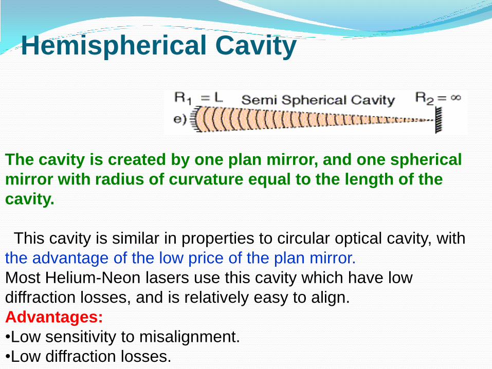
The cavity is created by one plan mirror, and one spherical
mirror with radius of curvature equal to the length of the
cavity.
This cavity is similar in properties to circular optical cavity, with
the advantage of the low price of the plan mirror.
Most Helium-Neon lasers use this cavity which have low
diffraction losses, and is relatively easy to align.
Advantages:
•Low sensitivity to misalignment.
•Low diffraction losses.
Hemispherical Cavity
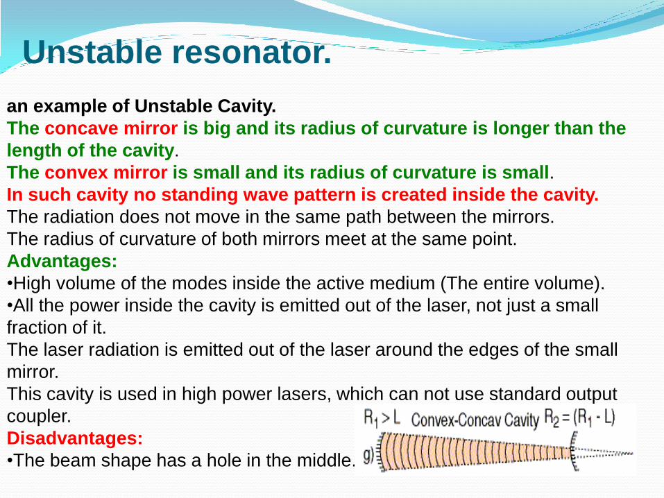
an example of Unstable Cavity.
The concave mirror is big and its radius of curvature is longer than the
length of the cavity.
The convex mirror is small and its radius of curvature is small.
In such cavity no standing wave pattern is created inside the cavity.
The radiation does not move in the same path between the mirrors.
The radius of curvature of both mirrors meet at the same point.
Advantages:
•High volume of the modes inside the active medium (The entire volume).
•All the power inside the cavity is emitted out of the laser, not just a small
fraction of it.
The laser radiation is emitted out of the laser around the edges of the small
mirror.
This cavity is used in high power lasers, which can not use standard output
coupler.
Disadvantages:
•The beam shape has a hole in the middle.
Unstable resonator.
Is a cavity in which the radiation is captured inside the cavity, creating standing waves while the beam move between the mirrors. The geometry of the cavity determines if the cavity is stable or not.It is possible to use unstable resonator only if the active medium have high gain, since the beam pass through the active medium less times than in stable cavity. For determining stability of a cavity, a stability criterion need to be defined.
Stability Criterion of the cavity A stable cavity
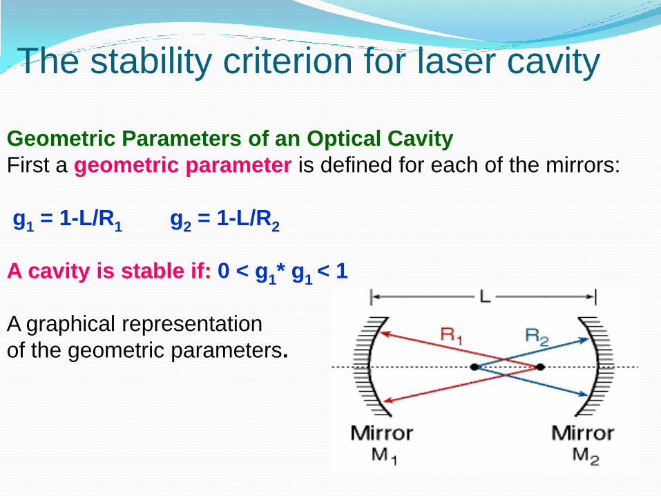
Geometric Parameters of an Optical Cavity
First a geometric parameter is defined for each of the mirrors:
g1 = 1-L/R1 g2 = 1-L/R2
A cavity is stable if: 0 < g1* g1 < 1
A graphical representation
of the geometric parameters.
The stability criterion for laser cavity

The stability criterion for laser cavity is: 0 < g1* g2 < 1
g1 = 1-L/R1 g2 = 1-L/R2
In the stability diagram the geometric parameters of the mirrors are the
axes x and y.
Figure show the stability diagram of all laser cavities.
Stability Diagram of an Optical Cavity

Example 4: Unstable Resonator
The laser cavity length is 1 [m].
At one end a concave mirror with radius of curvature of 1.5 [m].
At the other end a convex mirror with radius of curvature of 10 [cm]. Find if this
cavity is stable.
Solution to Example 4:
R1 = 1.5 [m].
As common in optics, a convex mirror is marked with minus sign:
R2 = - 0.1 [m]
g1 = 1-L/R1 = 1-1/1.5 = 0.333.
g2 = 1-L/R2 = 1+1/0.1 = 11
The product: g1*g2 = 11*0.333 >1
The product is greater than 1, so the cavity is unstable.
•The number of longitudinal modes is determined by the length of the cavity and
its index of refraction.
Transverse Laser Modes:
The basic transverse (TEM00) mode is a Gaussian:
•It has the lowest divergence.
•It can be focused to the smallest spot.
•Its Spatial coherence is the best of all the other modes.
•It stays with Gaussian distribution while passing through optical systems.
Stability Diagram:
The stability diagram describes the geometrical parameters of the laser
cavity:
g1 = 1- L/R1 g2 = 1- L/R2
The condition of stability:
0 < g1* g2 <1

Laser GainThe output power of the laser at specific moment is determined by two
conflicting factors:
1. Active medium gain - which depends on:
a) Population Inversion .
b) Fluorescence line-shape of the spontaneous emission that is related
to the lasing transition .
2. Losses in the laser, which include:
a) Reflections from end mirrors.
b) Radiation losses inside the active medium - due to absorption and
scattering.
c) Diffraction losses - Due to the finite size of the laser components.
It is clear that a required condition for lasing is:
In a round trip path of the radiation between the laser mirrors, the
gain must exceed ( or at least be equal to) the losses.
Fluorescence line shape of the laser
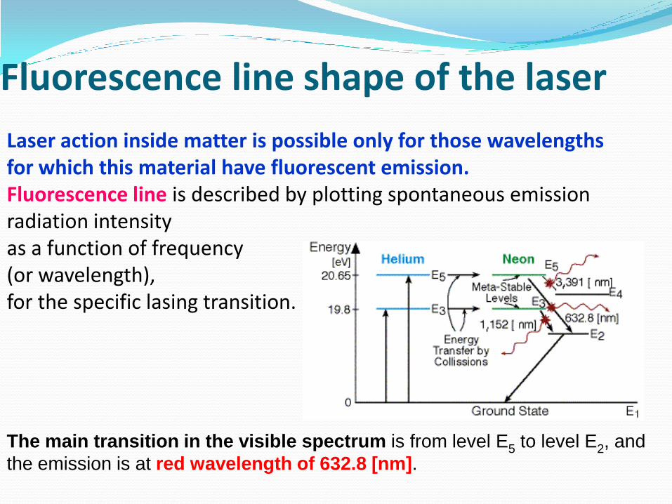
Laser action inside matter is possible only for those wavelengths for which this material have fluorescent emission.Fluorescence line is described by plotting spontaneous emission radiation intensity as a function of frequency (or wavelength), for the specific lasing transition.
The main transition in the visible spectrum is from level E5 to level E2, and
the emission is at red wavelength of 632.8 [nm].

Loop GainContrary to amplifying the radiation, there are many losses:
Scattering and absorption losses at the end mirrors.
Output radiation through the output coupler.
Scattering and absorption losses in the active medium, and
at the side walls of the laser.
Diffraction losses because of the finite size of the laser
components.
These losses cause some of the radiation not to take part in
the lasing process.
A necessary condition for lasing is that the total gain will
be a little higher than all the losses.
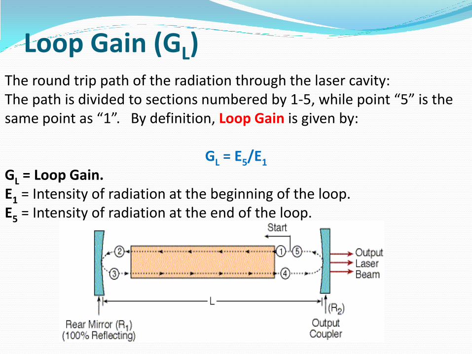
Loop Gain (GL)The round trip path of the radiation through the laser cavity: The path is divided to sections numbered by 1-5, while point “5” is the same point as “1”. By definition, Loop Gain is given by:
GL = E5/E1
GL = Loop Gain.E1 = Intensity of radiation at the beginning of the loop. E5 = Intensity of radiation at the end of the loop.

Calculating Loop Gain (GL) Without Losses
GA = Active medium gainE2 = GA*E1
we assumed that the length of the active medium is equal to the length of the cavity, such that the active medium feel the length of the laser cavity. On the way from point “2” to point “3”, As a result: E3 = R1*GA*E1
On the way from point “3” to point “4”, the radiation pass again through the active medium, and amplified. Thus: E4 = R1*GA
2*E1
On the way from point “4” to point “5”, the radiation is reflected from the output coupler, which have a reflectivity R2. Thus: E5 = R1* R2*GA
2*E1
This completes the loop.
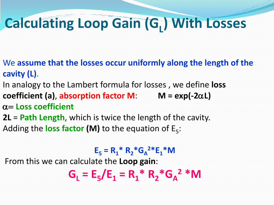
Calculating Loop Gain (GL) With Losses
We assume that the losses occur uniformly along the length of the cavity (L). In analogy to the Lambert formula for losses , we define loss coefficient (a), absorption factor M: M = exp(-2aL)a= Loss coefficient2L = Path Length, which is twice the length of the cavity. Adding the loss factor (M) to the equation of E5:
E5 = R1* R2*GA2*E1*M
From this we can calculate the Loop gain:
GL = E5/E1 = R1* R2*GA2 *M
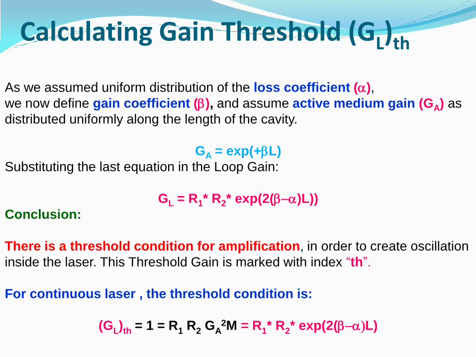
Calculating Gain Threshold (GL)th
As we assumed uniform distribution of the loss coefficient (a),
we now define gain coefficient (b), and assume active medium gain (GA) as
distributed uniformly along the length of the cavity.
GA = exp(+bL)
Substituting the last equation in the Loop Gain:
GL = R1* R2* exp(2(b-a)L))
Conclusion:
There is a threshold condition for amplification, in order to create oscillation
inside the laser. This Threshold Gain is marked with index “th”.
For continuous laser , the threshold condition is:
(GL)th = 1 = R1 R2 GA2M = R1* R2* exp(2(b-a)L)

Example
Active medium gain in a laser is 1.05.
Reflection coefficients of the mirrors are: 0.999, and 0.95.
Length of the laser is 30 [cm].
Loss coefficient is: a = 1.34*10-4 [cm-1].
Calculate:
1. The loss factor M.
2. The Loop gain (GL).
3. The gain coefficient (b).
Solution to example :
1. The loss factor M: M = exp2(-aL) = exp[-2(1.34*10-4)*30] = 0.992
2. The Loop gain (GL): GL = R1R2GA2M = 0.999*0.95*1.052*0.992 =
1.038
Since GL > 1, this laser operates above threshold.
3. The gain coefficient (b): GA = exp(bL)
Ln (GA) = bL
b= Ln (GA)/L = ln(1.05)/30 = 1.63*10-3 [cm-1]
The gain coefficient (b) is greater than the loss coefficient (a), as
expected.

ExampleHelium Neon laser operates in threshold condition . Reflection coefficients
of the mirrors are: 0.999, and 0.97. Length of the laser is 50 [cm]. Active
medium gain is 1.02.
Calculate:
1. The loss factor M.
2. The loss coefficient (a).
Solution :
Since the laser operates in threshold condition, GL = 1.
Using this value in the loop gain: GL = 1 = R1R2GA2M
1. The loss factor M:
M = 1/( R1R2GA2) = 1/(0.999*0.97*1.022) = 0.9919
As expected, M < 1. Since GL > 1, this laser operates above threshold.
2. The loss coefficient (a) is calculated from the loss factor:
M = exp(-2aL) : lnM = -2aL
a = lnM/(-2L) = ln(0.9919)/(-100) = 8.13*10-5 [cm-1]
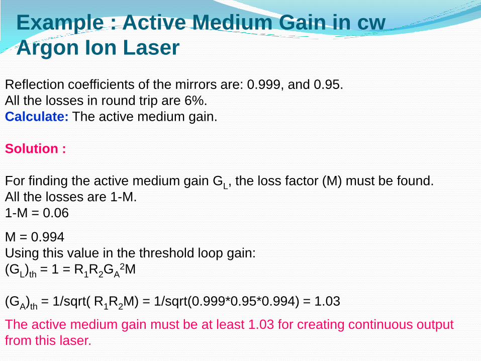
Example : Active Medium Gain in cw
Argon Ion Laser
Reflection coefficients of the mirrors are: 0.999, and 0.95.
All the losses in round trip are 6%.
Calculate: The active medium gain.
Solution :
For finding the active medium gain GL, the loss factor (M) must be found.
All the losses are 1-M.
1-M = 0.06
M = 0.994
Using this value in the threshold loop gain:
(GL)th = 1 = R1R2GA2M
(GA)th = 1/sqrt( R1R2M) = 1/sqrt(0.999*0.95*0.994) = 1.03
The active medium gain must be at least 1.03 for creating continuous output
from this laser.
Laser GainThe output power of the laser at specific moment is determined by two conflicting
factors:
1. Active medium gain - which depends on:
a) Population Inversion .
b) Fluorescence line-shape of the spontaneous emission that is related to the
lasing transition .
2. Losses in the laser, which include:
a) Reflections from end mirrors.
b) Radiation losses inside the active medium - due to absorption and
scattering.
c) Diffraction losses - Due to the finite size of the laser components.
It is clear that a required condition for lasing is:
In a round trip path of the radiation between the laser mirrors, the gain must
exceed ( or at least be equal to) the losses.
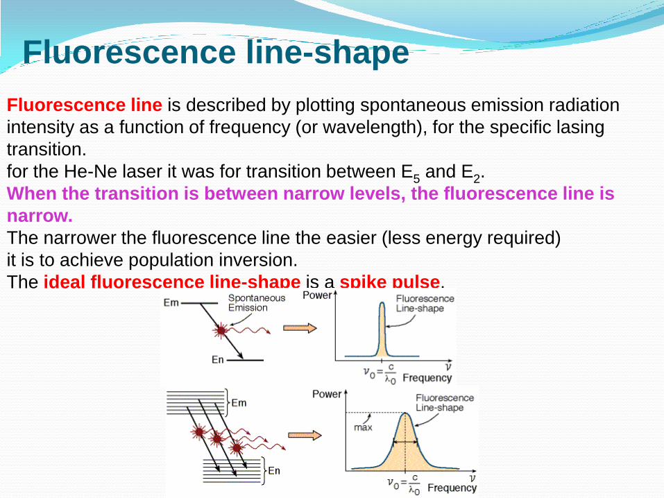
Fluorescence line-shape
Fluorescence line is described by plotting spontaneous emission radiation
intensity as a function of frequency (or wavelength), for the specific lasing
transition.
for the He-Ne laser it was for transition between E5 and E2.
When the transition is between narrow levels, the fluorescence line is
narrow.
The narrower the fluorescence line the easier (less energy required)
it is to achieve population inversion.
The ideal fluorescence line-shape is a spike pulse,
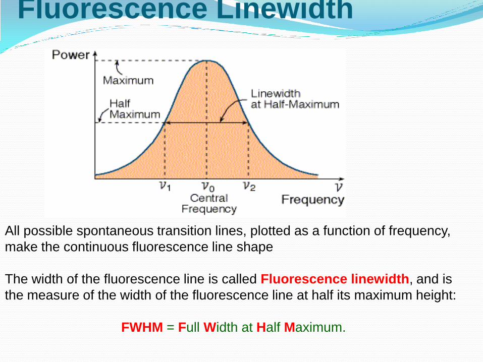
Fluorescence Linewidth
All possible spontaneous transition lines, plotted as a function of frequency,
make the continuous fluorescence line shape
The width of the fluorescence line is called Fluorescence linewidth, and is
the measure of the width of the fluorescence line at half its maximum height:
FWHM = Full Width at Half Maximum.
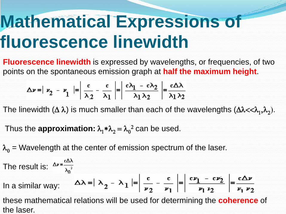
Mathematical Expressions of fluorescence linewidthFluorescence linewidth is expressed by wavelengths, or frequencies, of two
points on the spontaneous emission graph at half the maximum height.
The linewidth (D l) is much smaller than each of the wavelengths (Dl<<l1,l2).
Thus the approximation: l1*l2 = l02 can be used.
l0 = Wavelength at the center of emission spectrum of the laser.
The result is:
In a similar way:
these mathematical relations will be used for determining the coherence of
the laser.

Laser Gain Curve
There is a lot of similarity between the shape of the gain curve and the
fluorescence line. The reason is that the active medium gain curve is directly
proportional to the width of the fluorescence line of the spontaneous
emission.
it is important to distinguish between
the linewidth of the laser, and the
linewidth of specific longitudinal mode,
which can contain many longitudinal modes.
Broadening the Fluorescence line
Certain mechanisms are responsible for broadening the linewidth of a laser:
1. Natural broadening.
2. Doppler Broadening.
3. Pressure broadening.
For many applications, especially when temporal coherence is required a
small linewidth of the emitted laser wavelength is required.
Natural broadening.
This broadening is always present, and comes from the finite transition
time from the upper laser level to the lower laser level.
Natural linewidth is narrow: 104 - 108 [Hz], compared to the radiation frequency
of visible light: 1014 [Hz].
Each energy level has a specific width (Dn), and specific lifetime (Dt).
Natural broadening results from the Heisenberg uncertainty principle:
DE*Dt > h
DE = h* Dn
Dn > 1/ Dt
Numerical examples:
Dt = 10-8 [s] = = > Dn = 108 [Hz]
Dt = 10-4 [s] = = > Dn = 104 [Hz]
The longer the specific energy level transition lifetime, the narrower is its
linewidth.
Doppler Broadening
Doppler shift is a well known phenomena in wave motion.
It occurs when the source is in relative motion to the receiver.
The frequency detected is shifted by an amount determined by the relative
velocity between the source and the receiver.
Since gas molecules are in constant motion in random directions, each
molecule emit light while it is moving relative to the laser axis in a different
direction. These distribution of frequency shifts cause the broadening of the
laser linewidth.
Doppler broadening occur especially in gas lasers, as a result of movement
of gas molecules.
Its influence is mostly in low pressure gas lasers
Pressure (collisions) broadening.
It is caused by collisions between the molecules of the gas.
Pressure broadening is the largest broadening mechanism in gas lasers with
pressure of more than 10 mm Hg.
As the pressure increase, the broadening increase.
At constant pressure (P), as the temperature (T) increases:
PV = nRT
P = const = = > V increases when T increases.
Since the Volume (V) increases, the number of collisions decrease. Thus, pressure
((collisions) broadening decrease.
Numerical example:1.At room temperature, the linewidth of CO2 laser with gas pressure of 10 [torr] is 55
[MHz].
2.At room temperature, the linewidth of CO2 laser with gas pressure of 100 [torr] is 500
[MHz].
3.Above 100 [torr], the increase rate of broadening is about 6.5 [MHz] for each
increase in pressure of 1 [torr].

Linewidth broadening
the result of broadening of the fluorescence linewidth.
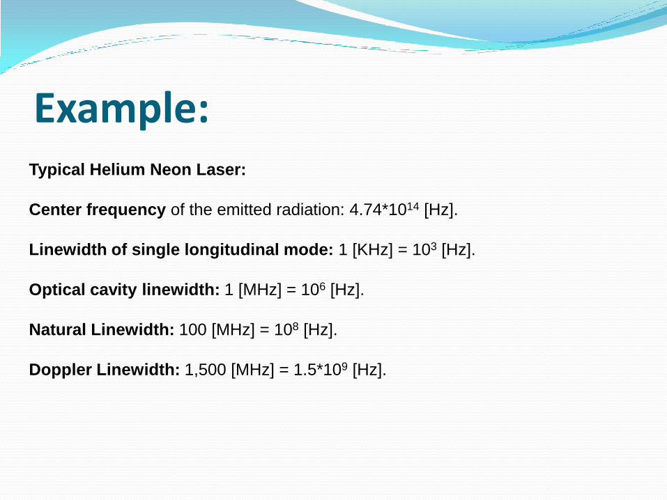
Example:Typical Helium Neon Laser:
Center frequency of the emitted radiation: 4.74*1014 [Hz].
Linewidth of single longitudinal mode: 1 [KHz] = 103 [Hz].
Optical cavity linewidth: 1 [MHz] = 106 [Hz].
Natural Linewidth: 100 [MHz] = 108 [Hz].
Doppler Linewidth: 1,500 [MHz] = 1.5*109 [Hz].


![ECEN689: Special Topics in Optical Interconnects Circuits ......• Long cavity length (300 m) results in multiple-longitudinal modes and large spectral linewidths [Sackinger] Typical](https://img.pdfslide.net/doc/110x75/60dd9e654bd05c796f2cf947/ecen689-special-topics-in-optical-interconnects-circuits-a-long-cavity.jpg)