Embed Size (px)
Citation preview
From: S.O. Kasap, Optoelectronics and Photonics: Principles and Practices, Second Edition, © 2013 Pearson Education, USA 1
JF, SCO 1617
From: S.O. Kasap, Optoelectronics and Photonics: Principles and Practices, Second Edition, © 2013 Pearson Education, USA 1
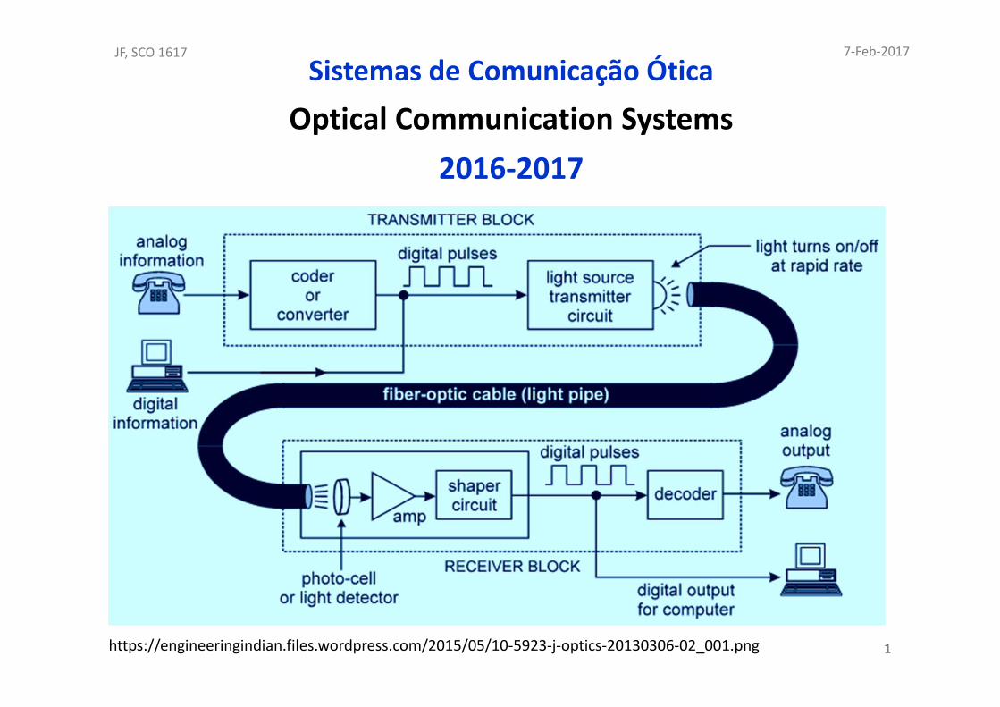
Sistemas de Comunicação Ótica
Optical Communication Systems
2016-2017
https://engineeringindian.files.wordpress.com/2015/05/10-5923-j-optics-20130306-02_001.png
7-Feb-2017

From: S.O. Kasap, Optoelectronics and Photonics: Principles and Practices, Second Edition, © 2013 Pearson Education, USA 2
JF, SCO 1617
From: S.O. Kasap, Optoelectronics and Photonics: Principles and Practices, Second Edition, © 2013 Pearson Education, USA 2
Reviews of electromagnetism:
concepts of geometrical optics and
wave optics, and quantum physics.
S.O. Kasap, Optoelectronics and Photonics: Principles and Practices, Second Edition, © 2013 Pearson Education© 2013 Pearson Education, Inc., Upper Saddle River, NJ. All rights reserved. This publication is prote cted by Copyright and written permission should be obtained from the
publisher prior to any prohibited reproduction, sto rage in a retrieval system, or transmission in any form or by any means, electronic, mechanical, photo copying, recording, or likewise. For information regarding permission(s), write to: Rights and Permissions Department, Pearso n Education, Inc., Upper Saddle River, NJ 07458.
7-Feb-2017

From: S.O. Kasap, Optoelectronics and Photonics: Principles and Practices, Second Edition, © 2013 Pearson Education, USA 3
JF, SCO 1617
From: S.O. Kasap, Optoelectronics and Photonics: Principles and Practices, Second Edition, © 2013 Pearson Education, USA 3
7-fev-17
From: S.O. Kasap, Optoelectronics and Photonics: Principles and Practices, Second Edition, © 2013 Pearson Education, USA 4
JF, SCO 1617
From: S.O. Kasap, Optoelectronics and Photonics: Principles and Practices, Second Edition, © 2013 Pearson Education, USA 4
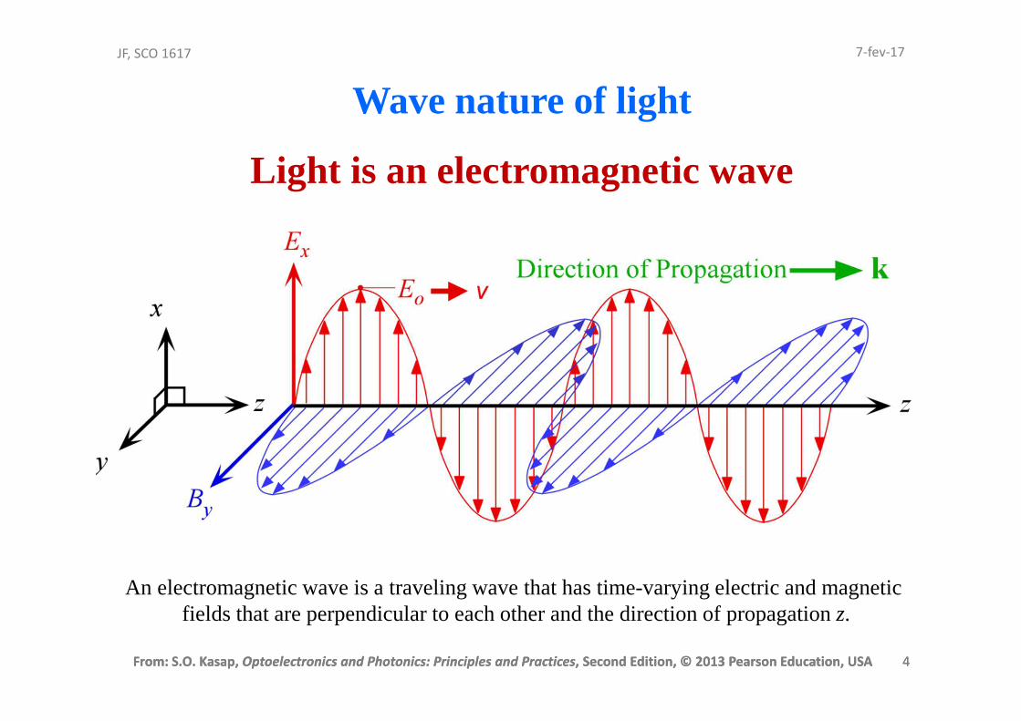
Wave nature of light
Light is an electromagnetic wave
An electromagnetic wave is a traveling wave that has time-varying electric and magnetic fields that are perpendicular to each other and the direction of propagation z.
7-fev-17
From: S.O. Kasap, Optoelectronics and Photonics: Principles and Practices, Second Edition, © 2013 Pearson Education, USA 5
JF, SCO 1617
From: S.O. Kasap, Optoelectronics and Photonics: Principles and Practices, Second Edition, © 2013 Pearson Education, USA 5
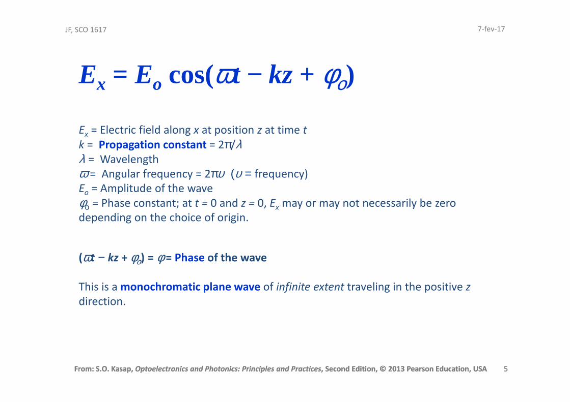
Ex = Eo cos(ωt − kz + φο)
Ex = Electric field along x at position z at time t
k = Propagation constant = 2π/λλ = Wavelength
ω = Angular frequency = 2πυ (υ = frequency)
Eo = Amplitude of the wave
φο = Phase constant; at t = 0 and z = 0, Ex may or may not necessarily be zero
depending on the choice of origin.
(ωt − kz + φο) = φ = Phase of the wave
This is a monochromatic plane wave of infinite extent traveling in the positive z
direction.
7-fev-17
From: S.O. Kasap, Optoelectronics and Photonics: Principles and Practices, Second Edition, © 2013 Pearson Education, USA 6
JF, SCO 1617
From: S.O. Kasap, Optoelectronics and Photonics: Principles and Practices, Second Edition, © 2013 Pearson Education, USA 6
Optical frequencies
Typical frequencies that are involved in
optoelectronic devices are in the infrared
(including far infrared), visible, and UV, and we
generically refer to these frequencies as optical frequencies
Somewhat arbitrary range:
Roughly 1012 Hz to 1016 Hz
7-fev-17

From: S.O. Kasap, Optoelectronics and Photonics: Principles and Practices, Second Edition, © 2013 Pearson Education, USA 7
JF, SCO 1617
From: S.O. Kasap, Optoelectronics and Photonics: Principles and Practices, Second Edition, © 2013 Pearson Education, USA 7
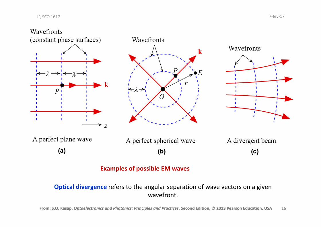
Wavefront
A surface over which the phase of a wave is constant is referred to as a wavefront
A wavefront of a plane wave is a plane perpendicular to the direction of propagation
The interaction of a light wave with a nonconducting medium (conductivity = 0) uses the electric field component Ex rather than By.
Optical field refers to the electric field Ex.
7-fev-17
From: S.O. Kasap, Optoelectronics and Photonics: Principles and Practices, Second Edition, © 2013 Pearson Education, USA 8
JF, SCO 1617
From: S.O. Kasap, Optoelectronics and Photonics: Principles and Practices, Second Edition, © 2013 Pearson Education, USA 8
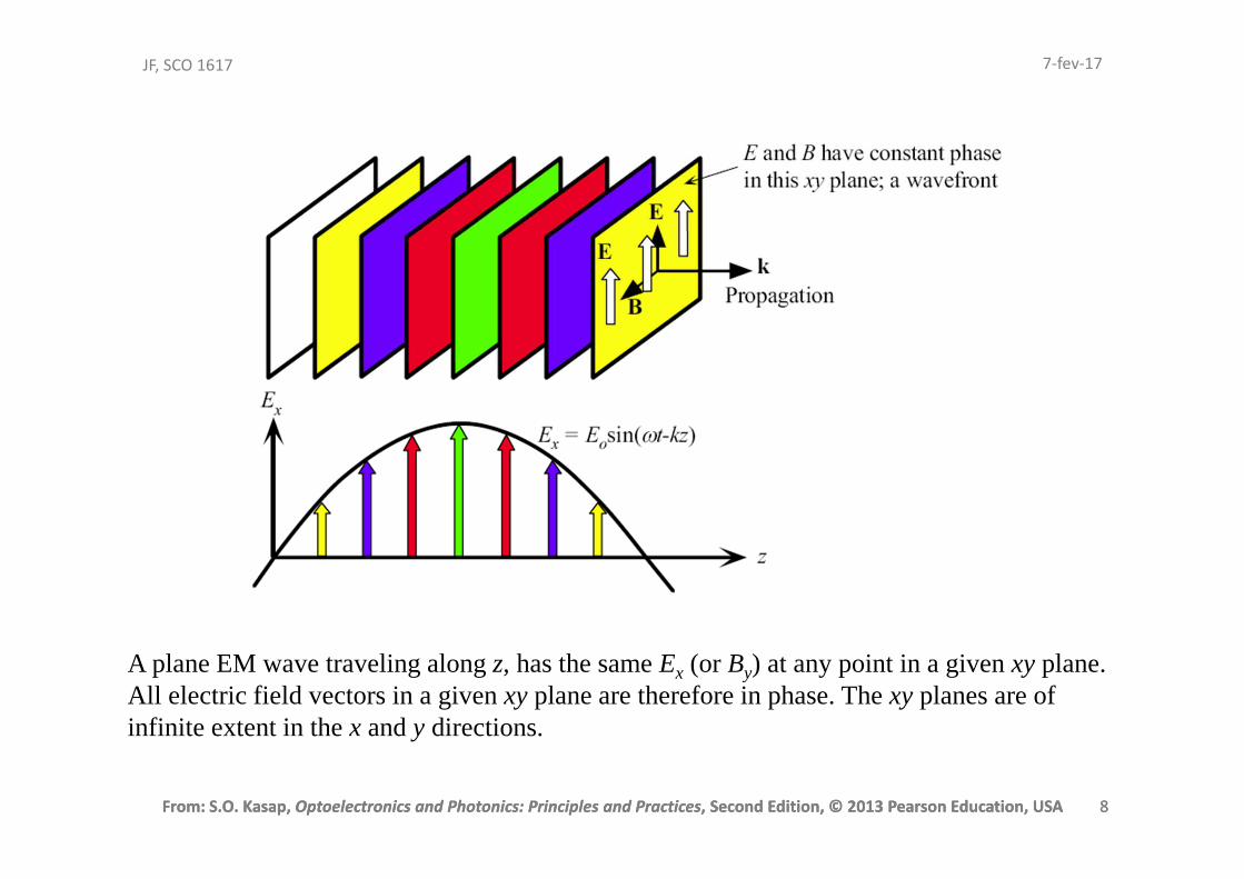
A plane EM wave traveling along z, has the same Ex (or By) at any point in a given xy plane.All electric field vectors in a given xy plane are therefore in phase. The xy planes are of infinite extent in the x and y directions.
7-fev-17
From: S.O. Kasap, Optoelectronics and Photonics: Principles and Practices, Second Edition, © 2013 Pearson Education, USA 9
JF, SCO 1617
From: S.O. Kasap, Optoelectronics and Photonics: Principles and Practices, Second Edition, © 2013 Pearson Education, USA 9
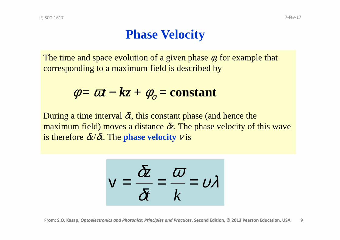
The time and space evolution of a given phase φ, for example that corresponding to a maximum field is described by
φ = ωt − kz + φο = constant
During a time interval δt, this constant phase (and hence the maximum field) moves a distance δz. The phase velocity of this wave is therefore δz/δt. The phase velocityv is
υλωδδ ===
kt
zv
Phase Velocity
7-fev-17
From: S.O. Kasap, Optoelectronics and Photonics: Principles and Practices, Second Edition, © 2013 Pearson Education, USA 10
JF, SCO 1617
From: S.O. Kasap, Optoelectronics and Photonics: Principles and Practices, Second Edition, © 2013 Pearson Education, USA 10
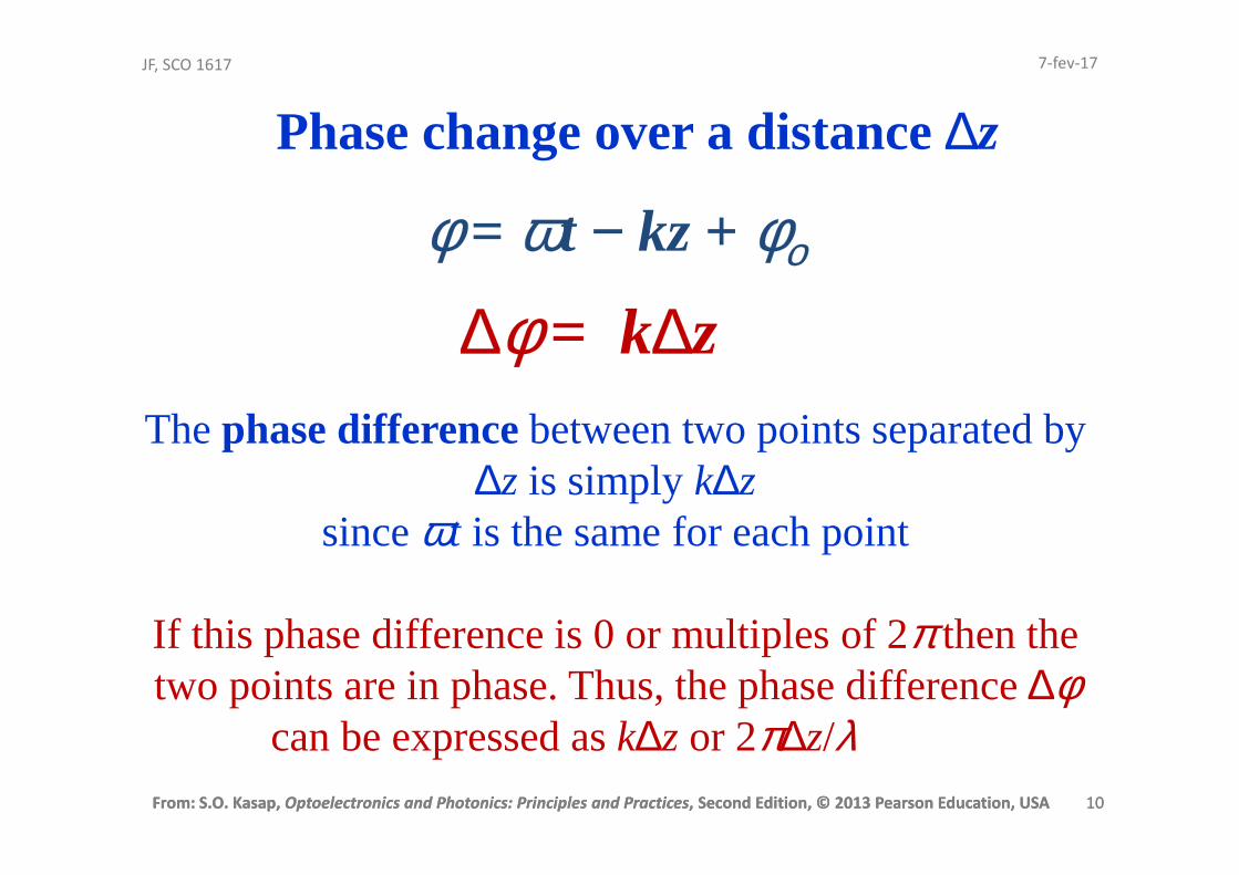
The phase differencebetween two points separated by ∆z is simply k∆z
since ωt is the same for each point
If this phase difference is 0 or multiples of 2π then the two points are in phase. Thus, the phase difference ∆φ
can be expressed as k∆z or 2π∆z/λ
Phase change over a distance ∆z
φ = ωt − kz + φο
∆φ = k∆z
7-fev-17

From: S.O. Kasap, Optoelectronics and Photonics: Principles and Practices, Second Edition, © 2013 Pearson Education, USA 11
JF, SCO 1617
From: S.O. Kasap, Optoelectronics and Photonics: Principles and Practices, Second Edition, © 2013 Pearson Education, USA 11
Recall that cosφ = Re[exp(jφ)]
where Re refers to the real part. We then need to take the real part of any complex result at the end of calculations. Thus,
Ex(z,t) = Re[Eoexp(jφο)expj(ωt − kz)]or
Ex(z,t) = Re[Ecexpj(ωt − kz)]
where Ec = Eoexp(jφo) is a complex number that represents the amplitude of the wave and includes the constant phase information φo.
Exponential Notation7-fev-17
From: S.O. Kasap, Optoelectronics and Photonics: Principles and Practices, Second Edition, © 2013 Pearson Education, USA 12
JF, SCO 1617
From: S.O. Kasap, Optoelectronics and Photonics: Principles and Practices, Second Edition, © 2013 Pearson Education, USA 12
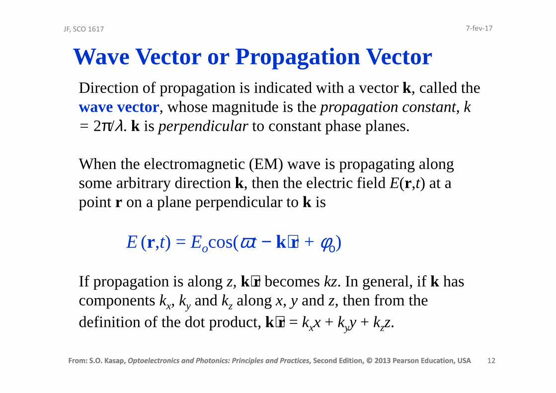
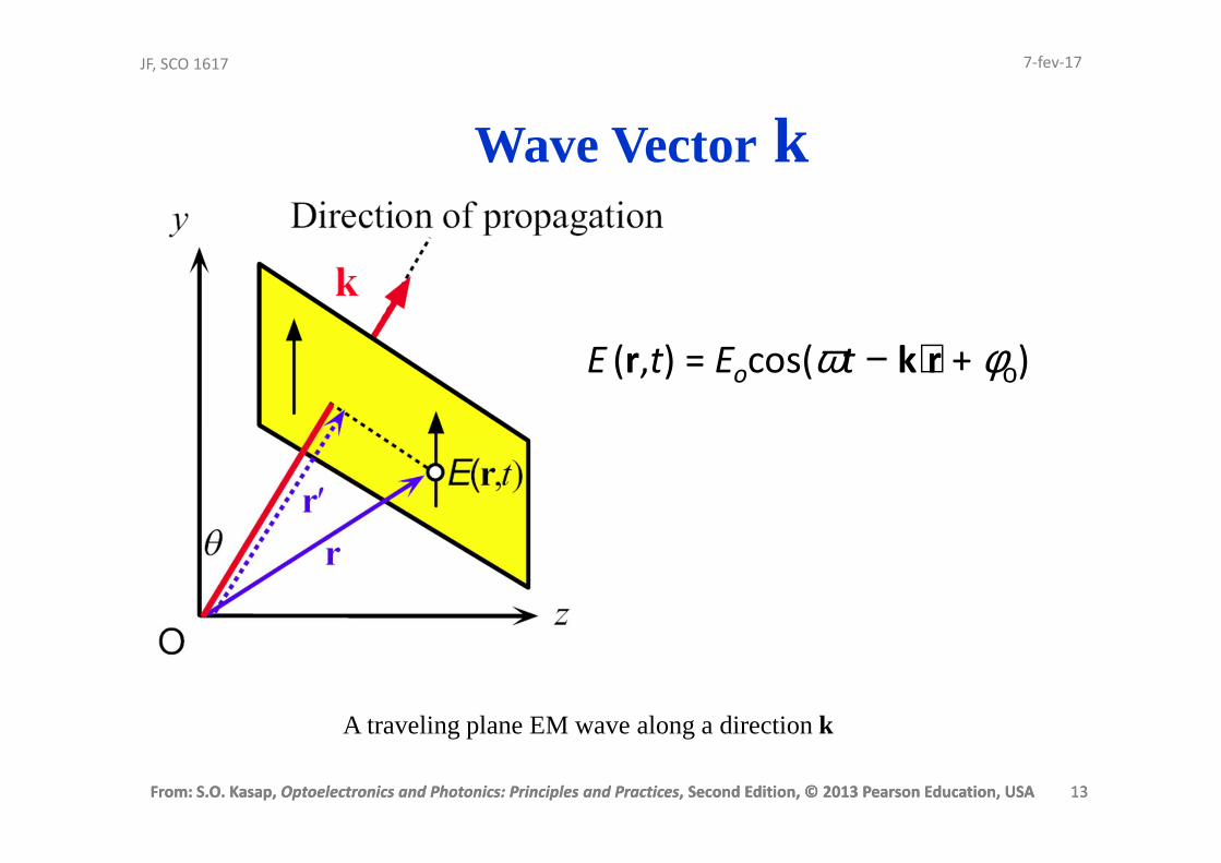
Direction of propagation is indicated with a vector k, called the wave vector, whose magnitude is the propagation constant, k = 2π/λ. k is perpendicular to constant phase planes.
When the electromagnetic (EM) wave is propagating along some arbitrary direction k, then the electric field E(r ,t) at a point r on a plane perpendicular to k is
E (r ,t) = Eocos(ωt − k⋅r + φο)
If propagation is along z, k⋅r becomes kz. In general, if k has components kx, ky and kz along x, y and z, then from the definition of the dot product, k⋅r = kxx + kyy + kzz.
Wave Vector or Propagation Vector7-fev-17
From: S.O. Kasap, Optoelectronics and Photonics: Principles and Practices, Second Edition, © 2013 Pearson Education, USA 13
JF, SCO 1617
From: S.O. Kasap, Optoelectronics and Photonics: Principles and Practices, Second Edition, © 2013 Pearson Education, USA 13
Wave Vector k
A traveling plane EM wave along a direction k
E (r,t) = Eocos(ωt − k⋅r + φο)
7-fev-17

From: S.O. Kasap, Optoelectronics and Photonics: Principles and Practices, Second Edition, © 2013 Pearson Education, USA 14
JF, SCO 1617
From: S.O. Kasap, Optoelectronics and Photonics: Principles and Practices, Second Edition, © 2013 Pearson Education, USA 14
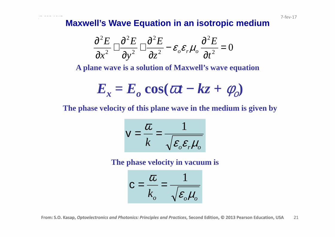
Maxwell’s Wave Equation
02
2
2
2
2
2
2
2
=∂∂−
∂∂+
∂∂+
∂∂
t
E
z
E
y
E
x
Eoro µεε
Ex = Eo cos(ωt − kz + φο)
A plane wave is a solution of Maxwell’s wave equation
Substitute into Maxwell’s Equation to show that this is a solution.
7-fev-17

From: S.O. Kasap, Optoelectronics and Photonics: Principles and Practices, Second Edition, © 2013 Pearson Education, USA 15
JF, SCO 1617
From: S.O. Kasap, Optoelectronics and Photonics: Principles and Practices, Second Edition, © 2013 Pearson Education, USA 15
Spherical Wave
)cos( krtr
AE −= ω
7-fev-17
From: S.O. Kasap, Optoelectronics and Photonics: Principles and Practices, Second Edition, © 2013 Pearson Education, USA 16
JF, SCO 1617
From: S.O. Kasap, Optoelectronics and Photonics: Principles and Practices, Second Edition, © 2013 Pearson Education, USA 16
Examples of possible EM waves
Optical divergence refers to the angular separation of wave vectors on a given
wavefront.
7-fev-17
From: S.O. Kasap, Optoelectronics and Photonics: Principles and Practices, Second Edition, © 2013 Pearson Education, USA 17
JF, SCO 1617
From: S.O. Kasap, Optoelectronics and Photonics: Principles and Practices, Second Edition, © 2013 Pearson Education, USA 17
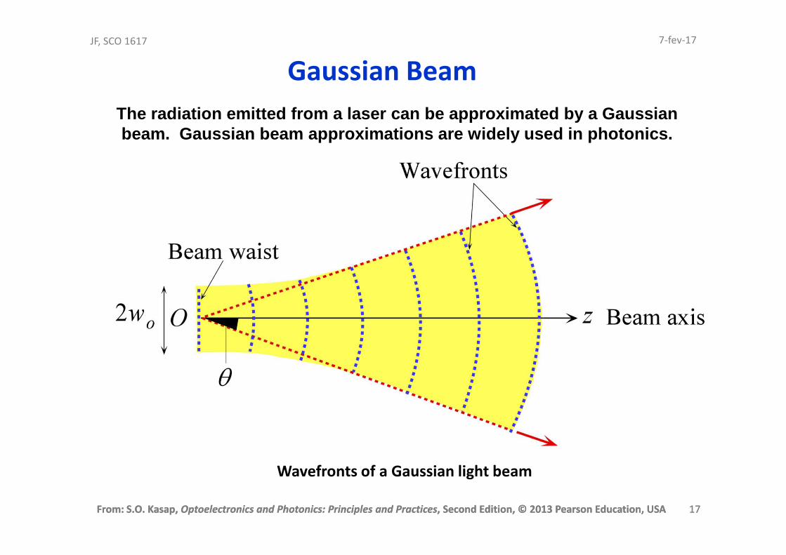
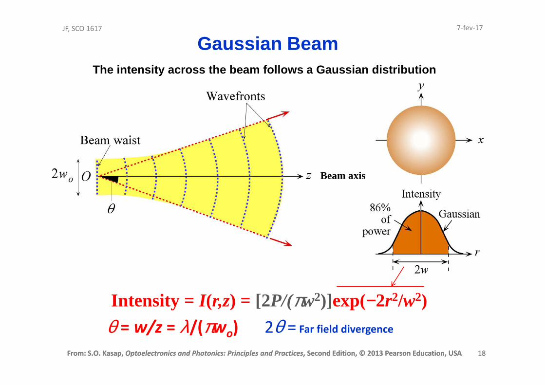
Gaussian Beam
Wavefronts of a Gaussian light beam
The radiation emitted from a laser can be approxima ted by a Gaussian beam. Gaussian beam approximations are widely used in photonics.
7-fev-17
From: S.O. Kasap, Optoelectronics and Photonics: Principles and Practices, Second Edition, © 2013 Pearson Education, USA 18
JF, SCO 1617
From: S.O. Kasap, Optoelectronics and Photonics: Principles and Practices, Second Edition, © 2013 Pearson Education, USA 18
Gaussian Beam
Intensity = I(r,z) = [2P/(πw2)]exp(−2r2/w2)
θ = w/z = λ/(πwo) 2θ = Far field divergence
The intensity across the beam follows a Gaussian di stribution
Beam axis
7-fev-17
From: S.O. Kasap, Optoelectronics and Photonics: Principles and Practices, Second Edition, © 2013 Pearson Education, USA 19
JF, SCO 1617
From: S.O. Kasap, Optoelectronics and Photonics: Principles and Practices, Second Edition, © 2013 Pearson Education, USA 19
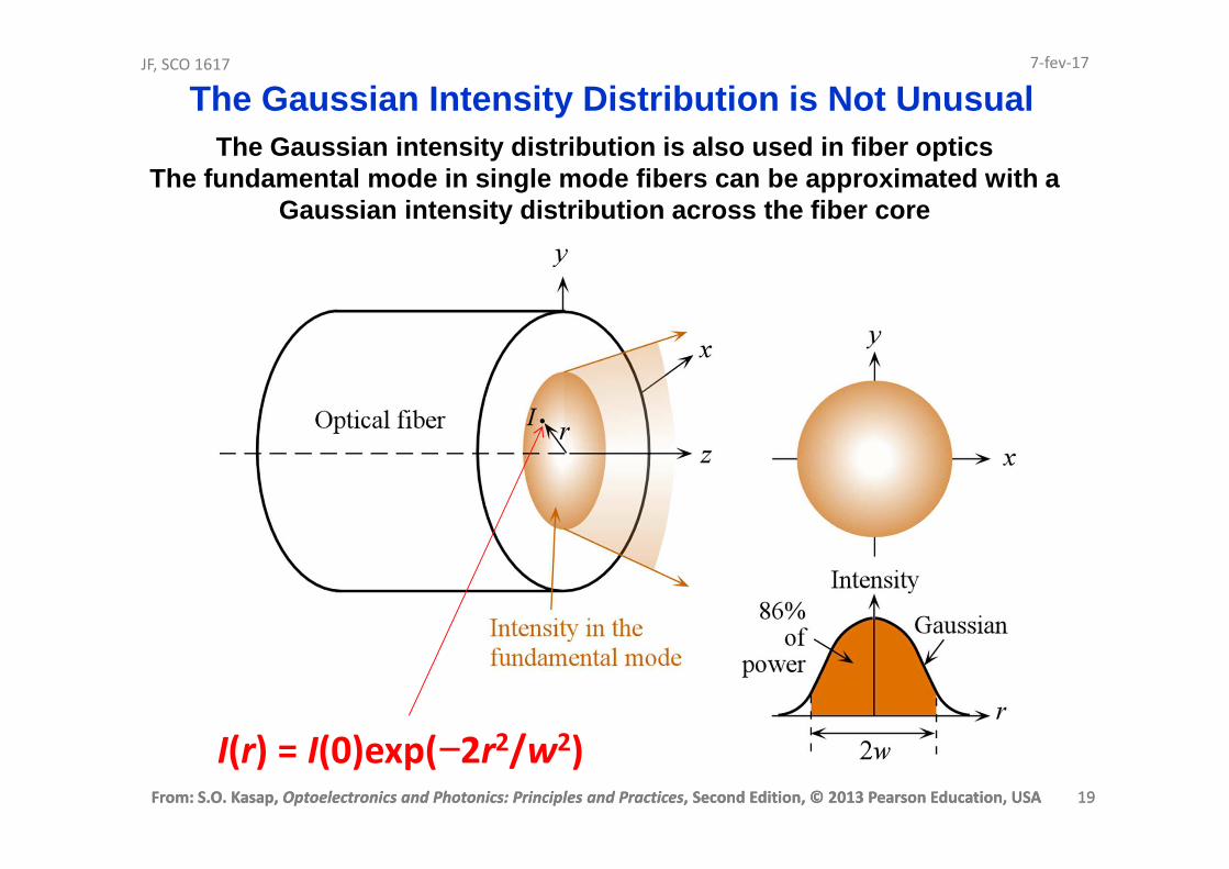
The Gaussian Intensity Distribution is Not Unusual
I(r) = I(0)exp(−2r2/w2)
The Gaussian intensity distribution is also used in fiber opticsThe fundamental mode in single mode fibers can be a pproximated with a
Gaussian intensity distribution across the fiber co re
7-fev-17
From: S.O. Kasap, Optoelectronics and Photonics: Principles and Practices, Second Edition, © 2013 Pearson Education, USA 20
JF, SCO 1617
From: S.O. Kasap, Optoelectronics and Photonics: Principles and Practices, Second Edition, © 2013 Pearson Education, USA 20
Refractive Index
When an EM wave is traveling in a dielectric
medium, the oscillating electric field polarizes the
molecules of the medium at the frequency of the
wave
The stronger is the interaction between the field
and the dipoles, the slower is the propagation of the
wave
7-fev-17
From: S.O. Kasap, Optoelectronics and Photonics: Principles and Practices, Second Edition, © 2013 Pearson Education, USA 21
JF, SCO 1617
From: S.O. Kasap, Optoelectronics and Photonics: Principles and Practices, Second Edition, © 2013 Pearson Education, USA 21
Maxwell’s Wave Equation in an isotropic medium
02
2
2
2
2
2
2
2
=∂∂−
∂∂+
∂∂+
∂∂
t
E
z
E
y
E
x
Eoro µεε
Ex = Eo cos(ωt − kz + φο)
A plane wave is a solution of Maxwell’s wave equation
orok µεεω 1==v
The phase velocity of this plane wave in the medium is given by
The phase velocity in vacuum is
oook µεω 1==c
7-fev-17
From: S.O. Kasap, Optoelectronics and Photonics: Principles and Practices, Second Edition, © 2013 Pearson Education, USA 22
JF, SCO 1617
From: S.O. Kasap, Optoelectronics and Photonics: Principles and Practices, Second Edition, © 2013 Pearson Education, USA 22
The relative permittivity εr measures the ease with which themedium becomes polarized and hence it indicates the extent ofinteraction between the field and the induced dipoles.
For an EM wave traveling in a nonmagnetic dielectric medium ofrelative permittivity εr, the phase velocity v is given by
Phase Velocity and εr
oor µεε1=ν
7-fev-17

From: S.O. Kasap, Optoelectronics and Photonics: Principles and Practices, Second Edition, © 2013 Pearson Education, USA 23
JF, SCO 1617
From: S.O. Kasap, Optoelectronics and Photonics: Principles and Practices, Second Edition, © 2013 Pearson Education, USA 23
Phase Velocity and εr
oor µεε1=ν
r
cn ε==
vRefractive indexndefinition
Refractive Index n7-fev-17
From: S.O. Kasap, Optoelectronics and Photonics: Principles and Practices, Second Edition, © 2013 Pearson Education, USA 24
JF, SCO 1617
From: S.O. Kasap, Optoelectronics and Photonics: Principles and Practices, Second Edition, © 2013 Pearson Education, USA 24
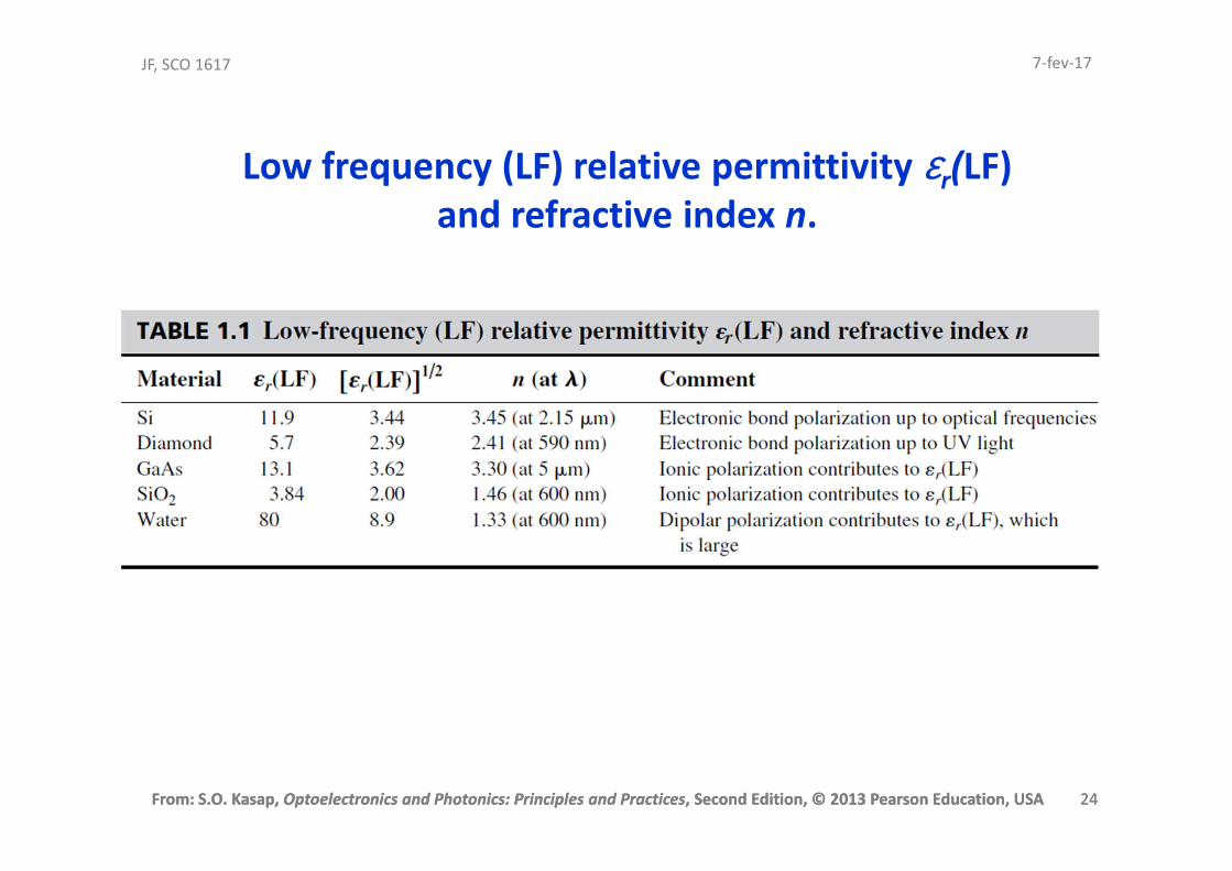
Low frequency (LF) relative permittivity εr(LF) and refractive index n.
7-fev-17
From: S.O. Kasap, Optoelectronics and Photonics: Principles and Practices, Second Edition, © 2013 Pearson Education, USA 25
JF, SCO 1617
From: S.O. Kasap, Optoelectronics and Photonics: Principles and Practices, Second Edition, © 2013 Pearson Education, USA 25
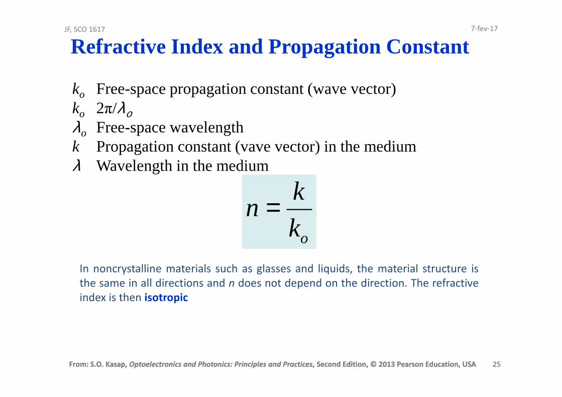
ko Free-space propagation constant (wave vector) ko 2π/λολo Free-space wavelengthk Propagation constant (vave vector) in the mediumλ Wavelength in the medium
ok
kn =
In noncrystalline materials such as glasses and liquids, the material structure is
the same in all directions and n does not depend on the direction. The refractive
index is then isotropic
Refractive Index and Propagation Constant7-fev-17
From: S.O. Kasap, Optoelectronics and Photonics: Principles and Practices, Second Edition, © 2013 Pearson Education, USA 26
JF, SCO 1617
From: S.O. Kasap, Optoelectronics and Photonics: Principles and Practices, Second Edition, © 2013 Pearson Education, USA 26
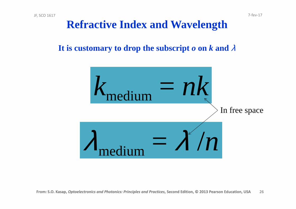
Refractive Index and Wavelength
λmedium = λ /n
kmedium = nkIn free space
It is customary to drop the subscript o on k and λ
7-fev-17

From: S.O. Kasap, Optoelectronics and Photonics: Principles and Practices, Second Edition, © 2013 Pearson Education, USA 27
JF, SCO 1617
From: S.O. Kasap, Optoelectronics and Photonics: Principles and Practices, Second Edition, © 2013 Pearson Education, USA 27
Crystals, in general, have nonisotropic, or anisotropic, properties
Typically noncrystalline solidssuch as glasses and liquids, and cubic crystals are optically isotropic; they possess only one refractive index for all directions
Refractive Index and Isotropy
7-fev-17

From: S.O. Kasap, Optoelectronics and Photonics: Principles and Practices, Second Edition, © 2013 Pearson Education, USA 28
JF, SCO 1617
From: S.O. Kasap, Optoelectronics and Photonics: Principles and Practices, Second Edition, © 2013 Pearson Education, USA 28
Group Velocity and Group Index
There are no perfect monochromatic waves
We have to consider the way in which a group of waves differing slightly in wavelength travel along the z-direction
7-fev-17
From: S.O. Kasap, Optoelectronics and Photonics: Principles and Practices, Second Edition, © 2013 Pearson Education, USA 29
JF, SCO 1617
From: S.O. Kasap, Optoelectronics and Photonics: Principles and Practices, Second Edition, © 2013 Pearson Education, USA 29
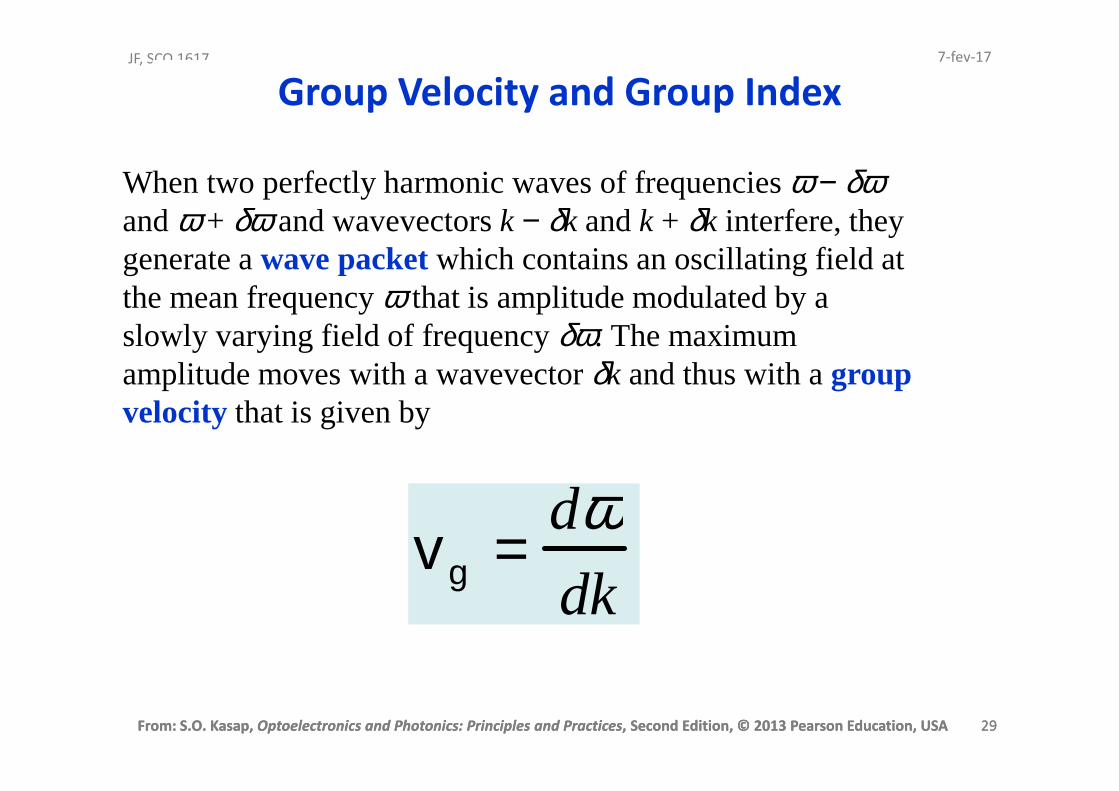
When two perfectly harmonic waves of frequencies ω − δωand ω + δω and wavevectors k − δk and k + δk interfere, they generate a wave packetwhich contains an oscillating field at the mean frequency ω that is amplitude modulated by a slowly varying field of frequency δω. The maximum amplitude moves with a wavevector δk and thus with a group velocity that is given by
vg =
dωdk
Group Velocity and Group Index7-fev-17

From: S.O. Kasap, Optoelectronics and Photonics: Principles and Practices, Second Edition, © 2013 Pearson Education, USA 30
JF, SCO 1617
From: S.O. Kasap, Optoelectronics and Photonics: Principles and Practices, Second Edition, © 2013 Pearson Education, USA 30
Group Velocity
Consider two sinusoidal waves that are
close in frequency, that is, they have
frequencies ω − δω and ω + δω.
Their wavevectors will be k − δk and k + δk.
The resultant wave is
Ex(z,t) = Eocos[(ω − δω)t − (k − δk)z] + Eocos[(ω + δω)t − (k + δk)z]
By using the trigonometric identity
cosA + cosB = 2cos[1/2(A − B)]cos[1/2(A + B)]
we arrive at
Ex(z,t) = 2Eocos[(δω)t − (δk)z][cos(ωt − kz)]
7-fev-17
Two slightly different wavelength waves traveling in the same direction result in a wave packet that has an amplitude variation that travels at the group velocity.
dk
dω=gv
From: S.O. Kasap, Optoelectronics and Photonics: Principles and Practices, Second Edition, © 2013 Pearson Education, USA 31
JF, SCO 1617
From: S.O. Kasap, Optoelectronics and Photonics: Principles and Practices, Second Edition, © 2013 Pearson Education, USA 31
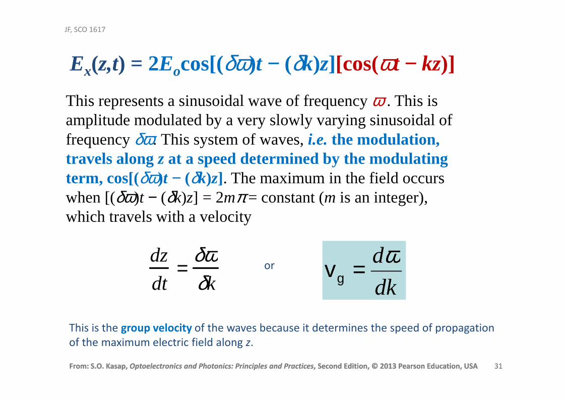
This represents a sinusoidal wave of frequency ω . This is amplitude modulated by a very slowly varying sinusoidal of frequency δω. This system of waves, i.e. the modulation, travels along z at a speed determined by the modulating term, cos[(δω)t − (δk)z]. The maximum in the field occurs when [(δω)t − (δk)z] = 2mπ = constant (m is an integer), which travels with a velocity
dz
dt=
δωδk
or
dk
dω=gv
This is the group velocity of the waves because it determines the speed of propagation
of the maximum electric field along z.
Ex(z,t) = 2Eocos[(δω)t − (δk)z][cos(ωt − kz)]

From: S.O. Kasap, Optoelectronics and Photonics: Principles and Practices, Second Edition, © 2013 Pearson Education, USA 32
JF, SCO 1617
From: S.O. Kasap, Optoelectronics and Photonics: Principles and Practices, Second Edition, © 2013 Pearson Education, USA 32
The group velocity therefore defines the speed with which
energy or information is propagated.
ω = 2πc/λo and k = 2πn/λo, λo is the free space wavelength.
Differentiate the above equations in red
dω = −(2πc/λo2)dλo
oo
ooo dd
dndndk λ
λλπλλπ
+−= )/2()/1(2 2
vg =
dωdk
oo
oo dd
dnndk λ
λλλπ
−−= )/2( 2
ooo
ooo
oo
d
dnn
c
dd
dnn
dc
dk
d
λλλ
λλλπ
λλπω
−=
−−
−==)/2(
)/2(
2
2
gv∴
From: S.O. Kasap, Optoelectronics and Photonics: Principles and Practices, Second Edition, © 2013 Pearson Education, USA 33
JF, SCO 1617
From: S.O. Kasap, Optoelectronics and Photonics: Principles and Practices, Second Edition, © 2013 Pearson Education, USA 33
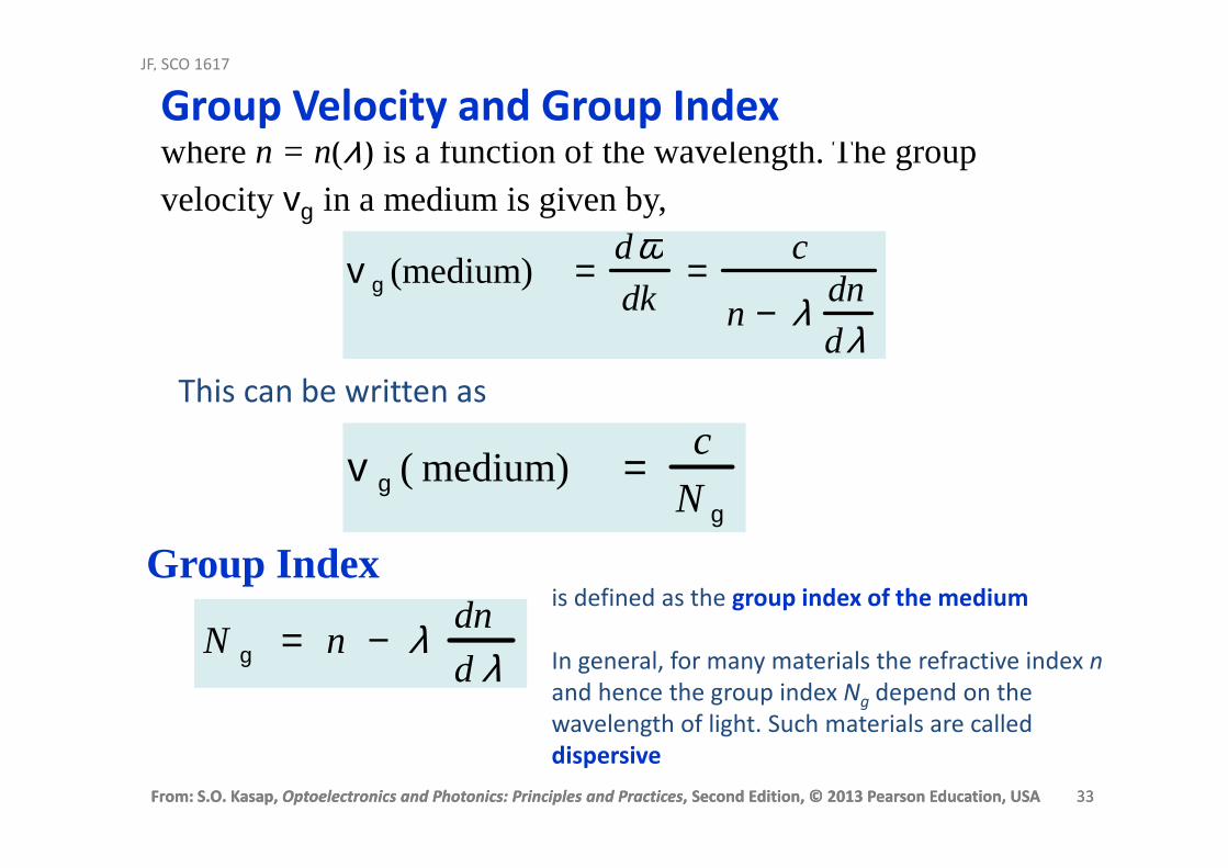
where n = n(λ) is a function of the wavelength. The group velocity vg in a medium is given by,
v g (medium) =dωdk
=c
n − λ dn
dλThis can be written as
v g ( medium) =
c
N g
Group Velocity and Group Index
N g = n − λ dn
d λ
Group Indexis defined as the group index of the medium
In general, for many materials the refractive index n
and hence the group index Ng depend on the
wavelength of light. Such materials are called
dispersive

From: S.O. Kasap, Optoelectronics and Photonics: Principles and Practices, Second Edition, © 2013 Pearson Education, USA 34
JF, SCO 1617
From: S.O. Kasap, Optoelectronics and Photonics: Principles and Practices, Second Edition, © 2013 Pearson Education, USA 34
Refractive index n and the group index Ng of pure SiO2 (silica) glass as a function of wavelength.
Refractive Index and Group Index

From: S.O. Kasap, Optoelectronics and Photonics: Principles and Practices, Second Edition, © 2013 Pearson Education, USA 35
JF, SCO 1617
From: S.O. Kasap, Optoelectronics and Photonics: Principles and Practices, Second Edition, © 2013 Pearson Education, USA 35
Magnetic Field, Irradiance and Poynting Vector
The magnetic field (magnetic induction) component By always accompanies
Ex in an EM wave propagation.
If v is the phase velocityof an EM wave in an isotropic dielectric medium
and n is the refractive index, then
yyx Bn
cBE == v
where v = (εoεrµo)−1/2 and n = ε1/2
7-Feb-2017
Photon energyA photon is an elementary particle, the quantum of the electromagnetic field
including electromagnetic radiation such as light.
ν= hphotonΕ h is the Planck's constant (6.6×10⁻³⁴ Js).
ν is frequency of the light.
From: S.O. Kasap, Optoelectronics and Photonics: Principles and Practices, Second Edition, © 2013 Pearson Education, USA 36
JF, SCO 1617
From: S.O. Kasap, Optoelectronics and Photonics: Principles and Practices, Second Edition, © 2013 Pearson Education, USA 36
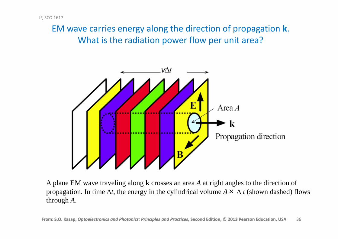
A plane EM wave traveling along k crosses an area A at right angles to the direction ofpropagation. In time ∆t, the energy in the cylindrical volume A× ∆ t (shown dashed) flowsthrough A.
EM wave carries energy along the direction of propagation k.
What is the radiation power flow per unit area?

From: S.O. Kasap, Optoelectronics and Photonics: Principles and Practices, Second Edition, © 2013 Pearson Education, USA 37
JF, SCO 1617
From: S.O. Kasap, Optoelectronics and Photonics: Principles and Practices, Second Edition, © 2013 Pearson Education, USA 37
As the EM wave propagates in the direction of the
wavevector k, there is an energy flow in this direction. The
wave brings with it electromagnetic energy.
The energy densities in the Ex and By fields are the same,
22
2
1
2
1y
oxro BE
µεε =
The total energy density in the wave is therefore εoεrEx2.
Energy Density in an EM Wave
From: S.O. Kasap, Optoelectronics and Photonics: Principles and Practices, Second Edition, © 2013 Pearson Education, USA 38
JF, SCO 1617
From: S.O. Kasap, Optoelectronics and Photonics: Principles and Practices, Second Edition, © 2013 Pearson Education, USA 38
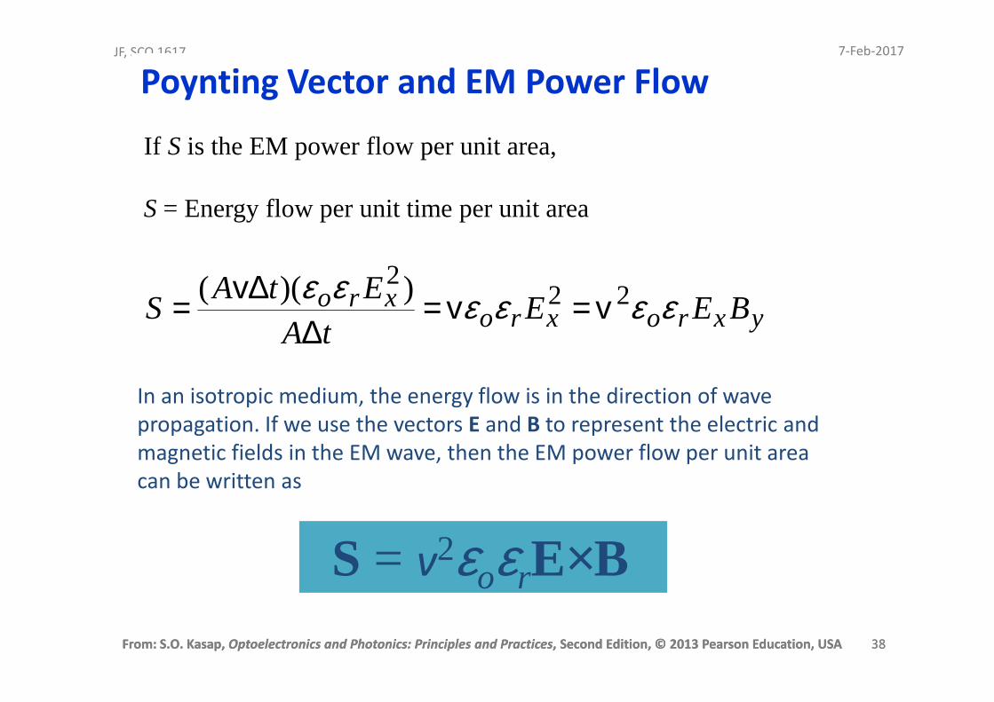
If S is the EM power flow per unit area,
S = Energy flow per unit time per unit area
yxroxroxro BEE
tA
EtAS εεεεεε 22
2 ))((vv
v ==∆
∆=
In an isotropic medium, the energy flow is in the direction of wave
propagation. If we use the vectors E and B to represent the electric and
magnetic fields in the EM wave, then the EM power flow per unit area
can be written as
Poynting Vector and EM Power Flow
S = v2εoεrE×B
7-Feb-2017
From: S.O. Kasap, Optoelectronics and Photonics: Principles and Practices, Second Edition, © 2013 Pearson Education, USA 39
JF, SCO 1617
From: S.O. Kasap, Optoelectronics and Photonics: Principles and Practices, Second Edition, © 2013 Pearson Education, USA 39
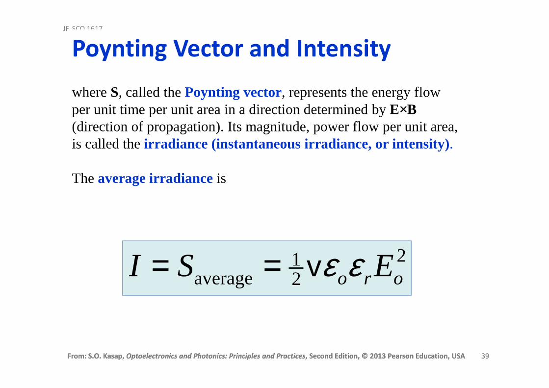
where S, called the Poynting vector, represents the energy flow per unit time per unit area in a direction determined by E×B(direction of propagation). Its magnitude, power flow per unit area, is called the irradiance (instantaneous irradiance, or intensity).
The average irradianceis
221
average oro ESI εεv==
Poynting Vector and Intensity
From: S.O. Kasap, Optoelectronics and Photonics: Principles and Practices, Second Edition, © 2013 Pearson Education, USA 40
JF, SCO 1617
From: S.O. Kasap, Optoelectronics and Photonics: Principles and Practices, Second Edition, © 2013 Pearson Education, USA 40
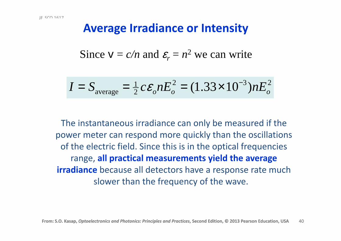
Since v = c/n and εr = n2 we can write
23221
average )1033.1( ooo nEnEcSI −×=== ε
The instantaneous irradiance can only be measured if the
power meter can respond more quickly than the oscillations
of the electric field. Since this is in the optical frequencies
range, all practical measurements yield the average irradiance because all detectors have a response rate much
slower than the frequency of the wave.
Average Irradiance or Intensity
From: S.O. Kasap, Optoelectronics and Photonics: Principles and Practices, Second Edition, © 2013 Pearson Education, USA 41
JF, SCO 1617
From: S.O. Kasap, Optoelectronics and Photonics: Principles and Practices, Second Edition, © 2013 Pearson Education, USA 41
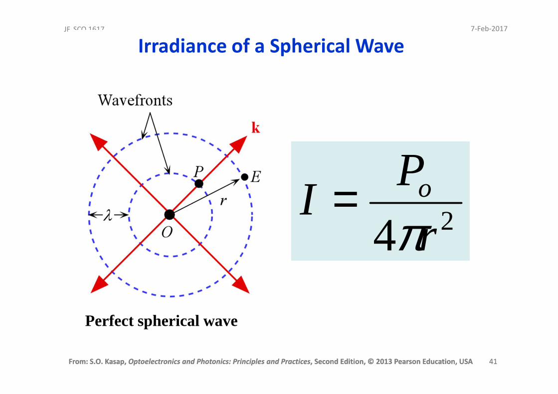
Irradiance of a Spherical Wave
24 r
PI o
π=
Perfect spherical wave
7-Feb-2017

From: S.O. Kasap, Optoelectronics and Photonics: Principles and Practices, Second Edition, © 2013 Pearson Education, USA 42
JF, SCO 1617
From: S.O. Kasap, Optoelectronics and Photonics: Principles and Practices, Second Edition, © 2013 Pearson Education, USA 42
Spherical wave front
9A4AAA
r
2r
3r
OSource
Po
Irradiance of a Spherical Wave
24 r
PI o
π=
From: S.O. Kasap, Optoelectronics and Photonics: Principles and Practices, Second Edition, © 2013 Pearson Education, USA 43
JF, SCO 1617
From: S.O. Kasap, Optoelectronics and Photonics: Principles and Practices, Second Edition, © 2013 Pearson Education, USA 43
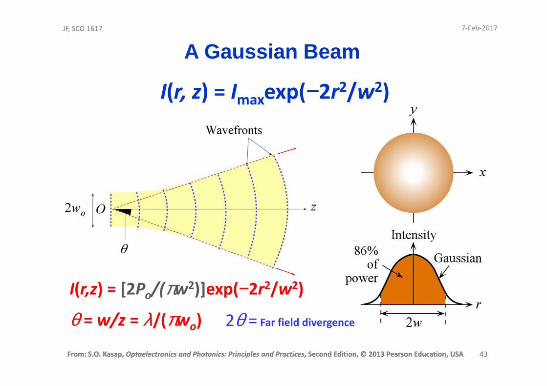
A Gaussian Beam
I(r, z) = Imaxexp(−2r2/w2)
I(r,z) = [2Po/(πw2)]exp(−2r2/w2)
θ = w/z = λ/(πwo) 2θ = Far field divergence
7-Feb-2017

From: S.O. Kasap, Optoelectronics and Photonics: Principles and Practices, Second Edition, © 2013 Pearson Education, USA 44
JF, SCO 1617
From: S.O. Kasap, Optoelectronics and Photonics: Principles and Practices, Second Edition, © 2013 Pearson Education, USA 44
Power in a Gaussian Beam
])/(2exp[)0()( 222 wrIrI −=
865.0
2)(
2)(
0
0 =
∫
∫∞
rdrrI
rdrrIw
π
πFraction of optical power
within 2w=
Area of a circular thin strip (annulus) with radius r is 2πrdr. Power passing through this strip is proportional to I(r) (2πr)dr
and

From: S.O. Kasap, Optoelectronics and Photonics: Principles and Practices, Second Edition, © 2013 Pearson Education, USA 45
JF, SCO 1617
From: S.O. Kasap, Optoelectronics and Photonics: Principles and Practices, Second Edition, © 2013 Pearson Education, USA 45
221
o
oo w
PI
π=
Io = Maximum irradiance at the center r = 0 at the waist
Example on
Gaussian Beam
Example 1.4.2 Power and irradiance of a Gaussian beamConsider a 5 mW HeNe laser that is operating at 633 nm, and has a spot size
that is 1 mm. Find the maximum irradiance of the beam and the axial
(maximum) irradiance at 25 m from the laser.
SolutionThe 5 mW rating refers to the total optical power Po available, and 633 nm is
the free space output wavelength λ. Apply
)( 221
ooo wIP π=
]m)105.0([W105 23213 −− ×=× πoI
Io = 1.273 W cm−2
∴
Corrected
7-Feb-2017