Embed Size (px)
Citation preview

Optical Configuration
03.11.2008 Advanced Virgo Review
Andreas Freise for the OSD subsystem

A. Freise Advanced Virgo Review 03.11.2008 Slide 2
Optical Simulation and Design
Scope of the OSD subsystem:
Optical design of the core interferometer (Michelson interferometer and Recycling cavities)
Core tasks:
Arm cavity geometry Arm cavity finesse Geometry of mirror and beam splitter substrates Power Recycling cavity Signal Recycling cavity Auxiliary beams and scattered light Optical simulations

A. Freise Advanced Virgo Review 03.11.2008 Slide 3
Design Strategy
Design drivers and constraints:
Interferometer design must be improved so that the sensitivity increase by a factor 10 can be achieved The positions and size of the vacuum tanks must be largely kept unchanged The envisaged joint operation with Advanced LIGO determines the timing
Strategy
Take existing Advanced LIGO design as start configuration Adapt parameters within the given constraints Provide always a consistent set of optical parameters to other subsystems Automate design tools so that parameter evolution can be done with low effort and high accuracy
A. Freise Advanced Virgo Review 03.11.2008 Slide 4
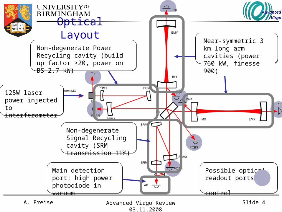
Optical LayoutNear-symmetric 3 km long arm cavities (power 760 kW, finesse 900)
Non-degenerate Power Recycling cavity (build up factor >20, power on BS 2.7 kW)
Non-degenerate Signal Recycling cavity (SRM transmission 11%)
125W laser power injected to interferometer
Main detection port: high power photodiode in vacuum
Possible optical readout ports for control

A. Freise Advanced Virgo Review 03.11.2008 Slide 5
Arm cavity geometry
Science driver: Coating Brownian noise
beam radius on mirror
Coating Brownian noise of one mirror:
Absolute beam size shouldbe as large as possible.

A. Freise Advanced Virgo Review 03.11.2008 Slide 6
Arm cavity geometry
Technical constraint: Mirror radius of curvature
In order to increase the beam the radii of curvature must be pushed close to the point of an instable cavity. `Corrective coatings' could be employed to achieve precise values (the accuracy of the metrology at LMA for radii of curvatures is ~0.1%). We have chosen the absolute value to be 2% away from cavity instability.
In a symmetric 3km cavity thiswould mean Rc > 1530.
mode non-degeneracy

A. Freise Advanced Virgo Review 03.11.2008 Slide 7
Arm cavity geometry
Technical constraint: Mirror size
Beam radius should be five to six times smaller than the coating diameter to keep the clipping losses below 1ppm (including a safety margin).
Coating size is limited by manufacturing process.
Mirror size: 35cmBeam size: 5 to 7cm

A. Freise Advanced Virgo Review 03.11.2008 Slide 8
Arm cavity geometry
Method: Near symmetric mirror curvatures
coating thickness
Beam size is determined by mirror radii of curvature:
3 m 6 m
Asymmetric coating thickness leads so a slight asymmetry for the radii of curvatures:

A. Freise Advanced Virgo Review 03.11.2008 Slide 9
Non-degenerate Recycling cavities
Science driver: Signal loss due to scattering into higher-order modes
Thermal effects or misalignmentsscatter light into higher-order modes so that optical signal is lost. Non-degenerate cavities can reduce this effect.
Commissioning experience shows that degenerate cavities cause problems for control signals. Y. Pan showed in 2006 that also GW signal is lost.
Degenerate cavity
First design options

A. Freise Advanced Virgo Review 03.11.2008 Slide 10
Non-degenerate Recycling cavities
Technical constraint: Size of vacuum system limits length of Recycling cavities
PRM2 in PR tower PRM2 in PR tower No change for BS,IMX or IMY No change for BS,IMX or IMY
PRM1 and PRM3in injection tower PRM1 and PRM3in injection tower
Non-degenerate cavities must be longer than the Rayleigh range of the beam. The arm cavity beam has a Rayleigh range of 200m.

A. Freise Advanced Virgo Review 03.11.2008 Slide 11
Non-degenerate Recycling cavities
Method: Focusing elements inside the Recycling cavities
Use beam propagation calculus to optimize radii of curvatures of the optical elements inside the recycling cavities for a given total length and single-trip Gouy phase.
Design procedure has been established, first draft design for Power Recycling cavity:
IMX
Length total: 24 to 25 m
limx = 10 cm lx = 5.5 m lprm3 = 10 m lprm2 = 4.5 mlprm1 = 4.5 m
component PRM1 PRM2 PRM3 BS IMX (AR)
Rc [m] 2.1 -1.8 30 10.5
w [mm] 1.8 2.2 16.5 38.5 50

A. Freise Advanced Virgo Review 03.11.2008 Slide 12
Signal Recycling Science driver: Sensitivity optimisation (quantum noise reduction)
The Signal Recycling (SR) mirror in the interferometer output makes the detector resonant fora certain signal frequency inorder to reduce quantum noise.
SR allows us to tune the sensitivity curve - also during operation.
SR is a mature optical techniquedeveloped over 10 years in theGEO collaboration and currently planned for all second-generation detectors.
Optimize parameters of SR mirror: microscopic position (tuning) power transmission

A. Freise Advanced Virgo Review 03.11.2008 Slide 13
Signal Recycling
Technical constraint: Fundamental noise sources
A vacuum tank for the Signal Recycling mirror is already present in the Virgo vacuum system.
The potential of the detectoroptimisation is limited by thermalnoise above ~ 30 Hz and ultimately gravity gradient noiseat lower frequencies.

A. Freise Advanced Virgo Review 03.11.2008 Slide 14
Signal Recycling
Method: Optimize NS-NS inspiral range
The SNR for a NS-NS inspiralis given by the integral with a known frequency dependence:
The SR parameters aretuned in order to maximise
the accumulated signal.
SNR=
SR tuning: 0.15 radSR transmission: 11%

A. Freise Advanced Virgo Review 03.11.2008 Slide 15
Summary
Current baseline:
arm cavity geometry fixed mirror substrate geometry fixed beam splitter geometry
currently being adapted to new beam size
recycling cavity design chosen, parameters to be evaluated
arm cavity finesse to be optimized

A. Freise Advanced Virgo Review 03.11.2008 Slide 16
Next steps
Geometry of core optics:
Preliminary design has been proposed and will now be checked in detail for consistency Optical parameters will be refined in an iterative process, based on a study of their impact on other subsystems
Arm cavity finesse:
The finesse of the arm cavities is one of the dominant scaling factors for the influence of noise from the small interferometer (BS, IM, PRM, SRM) A trade-off study for the arm cavity finesse is strongly linked to the R+D program concerning mirror surface losses

A. Freise Advanced Virgo Review 03.11.2008 Slide 17
...end

A. Freise Advanced Virgo Review 03.11.2008 Slide 18
Example of Gouy phase and beam size

A. Freise Advanced Virgo Review 03.11.2008 Slide 19
Searching the parameter space
RC,IMX=10m
Gouy Phase
Beam Size

A. Freise Advanced Virgo Review 03.11.2008 Slide 20
Searching the parameter space
RC,IMX=flat
Gouy Phase
Beam Size