Embed Size (px)
Citation preview
Optical head employing aconcentric-circular focusing grating coupler
Seiji Nishiwaki, Jun-ichi Asada, and Shinji Uchida
An optical head employing a concentric-circular grating coupler (CGC) and a concentric-circular focusinggrating coupler (CFGC) is proposed, and its operating principle and characteristics are reported.Satisfaction with a prerequisite for the head, i.e., the removal of aberrations caused by deviations inwavelength and the effective index, is theoretically achieved by application of the concept of optimizationof an annular aperture. With CGC and CFGC fabricated by an electron-beam-writing method, weexperimentally confirmed its fundamental characteristics of light input, waveguiding, output, andconvergence, with an elliptical focusing spot converging at half-intensity widths of 1.8 and 4.0 pum.
Key words: Optical head, waveguide, grating coupler, annular aperture, aberration, electron-beamwriting.
1. Introduction
A new light-converging element called a focusinggrating coupler (FGC) has been proposed and re-search on its focusing characteristics and fabricationmethod and their evaluation have been carried out.1In addition, substituting an integrated optical headthat employs an FGC for the conventional opticalhead made of such optical elements as a lens andprism has been proposed; its fundamental focusingand light-detecting characteristics have been evalu-ated.2
However, since the FGC structure is asymmetricalwith respect to the optical axis, and the diffractionangle of radiated light from the FGC is highly depen-dent on the wavelength of the source light and theeffective index of its waveguide layer, the large aberra-tions caused by their deviations, mainly astigmatismand coma, were found to be a problem.3 Since thisproblem is particularly serious when the FGC isincorporated in an integrated optical pickup, whichmust have a large numerical aperture, the actualapplication of the FGC to the optical pickup wasfound to be difficult in its present stage.
To overcome this problem, the authors propose aconcentric-circular focusing grating coupler (CFGC),with a new FGC construction, together with an
The authors are with the Device Process Technology ResearchLaboratory, Matsushita Electric Industrial Company, Ltd., 3-1-1Yagumo-nakamachi, Moriguchi, Osaka 570, Japan.
Received 2 July 1992.0003-6935/94/101819-09$06.00/0.3 1994 Optical Society of America.
optical head employing a CFGC.4 In this paper wereport on the characteristics of an optical head employ-ing a CFGC and the focusing characteristics of aCFGC fabricated by an electron-beam-writing method.
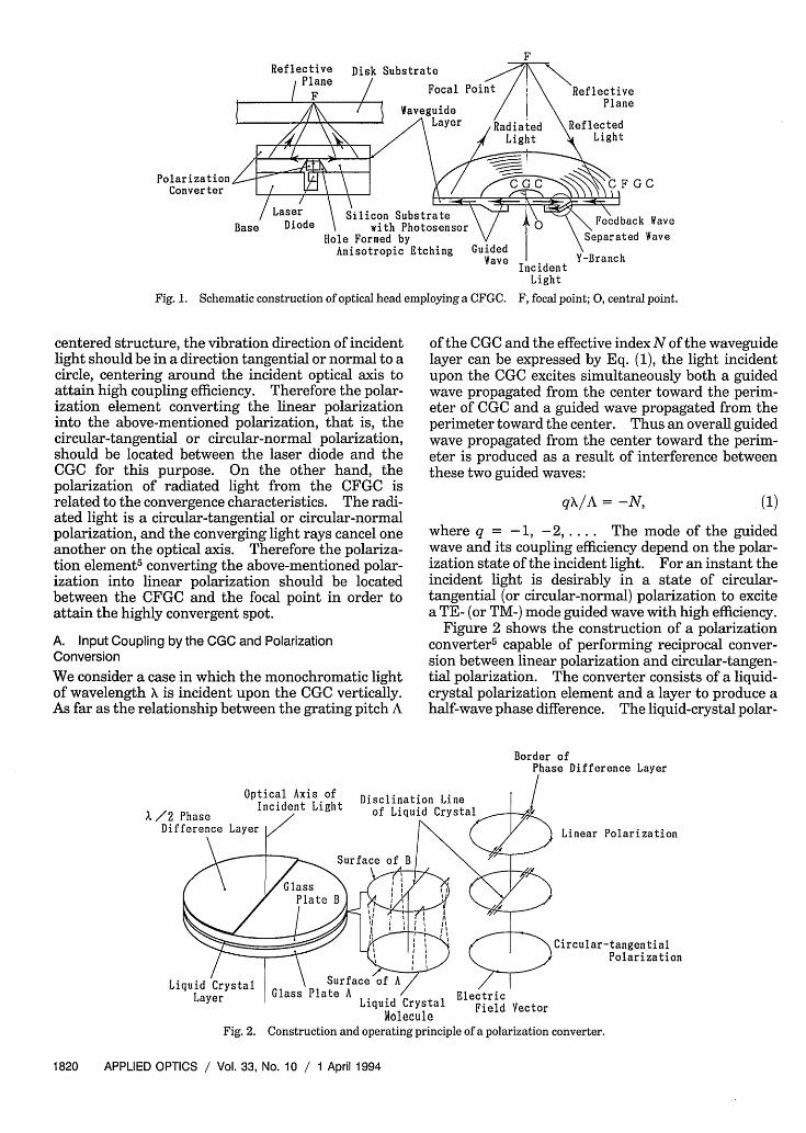
2. Optical Head Employing a CFGCFigure 1 shows a schematic perspective view of theoptical head employing a concentric-circular gratingcoupler (CGC) and a CFGC. These couplers aremade of a concentric-circular grating formed on awaveguide layer, and the CFGC with a radially variedperiod is concentrically formed with the CGC with aconstant period. The waveguide layer is formed on atransparent substrate or on a transparent bufferlayer formed on a silicon substrate. If a siliconsubstrate is chosen as the substrate, it must bepartially etched so that the CGC is visible from theback side. In this case the buffer layer functions as astopper in the etching process. The light emittedfrom a laser diode is introduced onto the CGC throughan etched hole in the silicon substrate and is con-verted into guided light traveling from the centertoward the CFGC. This guided light is radiated bythe CFGC and converges at the focal point. Thelight reflected from the surface of an optical disk isincident on the CFGC and is converted into guidedlight that propagates along the centripetal direction.The feedback guided light is separated by a planar Ybranch formed on a ring band between the CGC andthe CFGC and is detected by a photosensor fabricatedon a silicon substrate.
Moreover the input coupling is related to thepolarization of incident light. Since the CGC has a
1 April 1994 / Vol. 33, No. 10 / APPLIED OPTICS 1819
Reflective Disk Substrate/.Plane /
I Focal
Polarization IConverter //
Laser Silicon SubstrateBase Diode with Photosensor
Hole Formed byAnisotropic Etching Guided
Wave
Fig. 1. Schematic construction of optical head employing a CFGC.
centered structure, the vibration direction of incidentlight should be in a direction tangential or normal to acircle, centering around the incident optical axis toattain high coupling efficiency. Therefore the polar-ization element converting the linear polarizationinto the above-mentioned polarization, that is, thecircular-tangential or circular-normal polarization,should be located between the laser diode and theCGC for this purpose. On the other hand, thepolarization of radiated light from the CFGC isrelated to the convergence characteristics. The radi-ated light is a circular-tangential or circular-normalpolarization, and the converging light rays cancel oneanother on the optical axis. Therefore the polariza-tion element5 converting the above-mentioned polar-ization into linear polarization should be locatedbetween the CFGC and the focal point in order toattain the highly convergent spot.
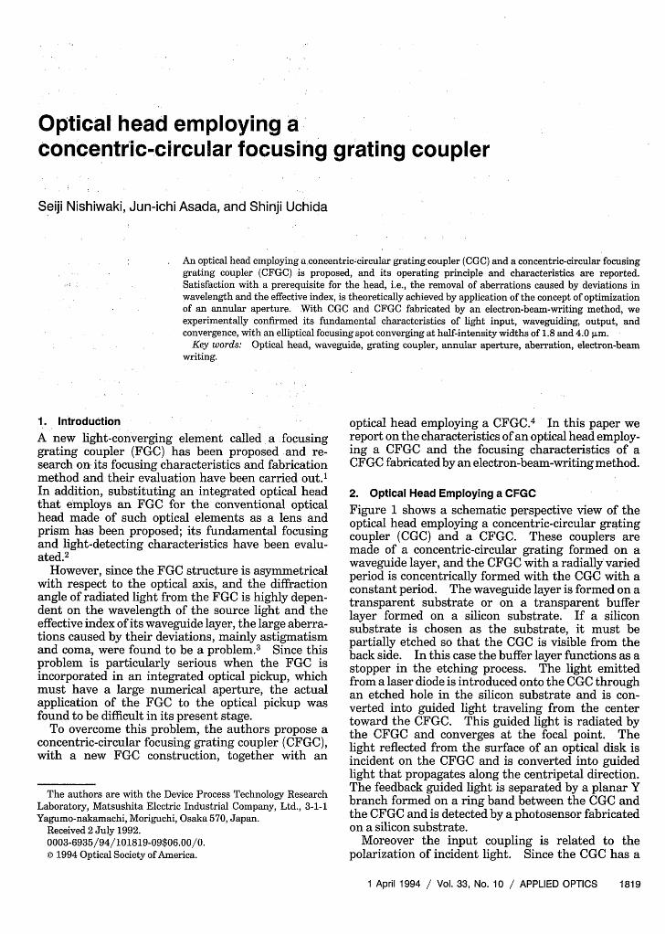
A. Input Coupling by the CGC and PolarizationConversionWe consider a case in which the monochromatic lightof wavelength is incident upon the CGC vertically.As far as the relationship between the grating pitch A
IncidentLight
F, focal point; 0, central point.
of the CGC and the effective index N of the waveguidelayer can be expressed by Eq. (1), the light incidentupon the CGC excites simultaneously both a guidedwave propagated from the center toward the perim-eter of CGC and a guided wave propagated from theperimeter toward the center. Thus an overall guidedwave propagated from the center toward the perim-eter is produced as a result of interference betweenthese two guided waves:
qX/A = -N, (1)
where q = -1, -2 .... The mode of the guidedwave and its coupling efficiency depend on the polar-ization state of the incident light. For an instant theincident light is desirably in a state of circular-tangential (or circular-normal) polarization to excitea TE- (or TM-) mode guided wave with high efficiency.
Figure 2 shows the construction of a polarizationconverter 5 capable of performing reciprocal conver-sion between linear polarization and circular-tangen-tial polarization. The converter consists of a liquid-crystal polarization element and a layer to produce ahalf-wave phase difference. The liquid-crystal polar-
Optical Axis of Disclination Line
A /2 Phase Incident Light of Liquid Cryst,Difference Layer l/ N
Circular-tangentialPolarization
I Liquid Crystal Field VectorMolecule 1
Fig. 2. Construction and operating principle of a polarization converter.
1820 APPLIED OPTICS / Vol. 33, No. 10 / 1 April 1994
F
< -- Transmission Axis~ Aligning Direction
Incident
Light
If
Light
/ Polarization \Polarizer Converter Analyzer
95 = 0 q5 = /2
Fig. 3. Experiment for verifying conversion from linear to circular-tangential polarization.
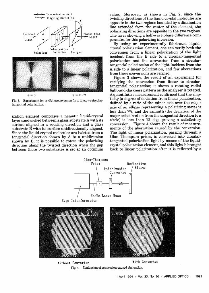
ization element comprises a nematic liquid-crystallayer sandwiched between a glass substrate A with itssurface aligned in a rotating direction and a glasssubstrate B with its surface unidirectionally aligned.Since the liquid-crystal molecules are twisted from atangential direction shown by A to a unidirectionshown by B, it is possible to rotate the polarizingdirection along the twisted direction when the gapbetween these two substrates is set at an optimum
value. Moreover, as shown in Fig. 2, since thetwisting directions of the liquid-crystal molecules areopposite in the two regions bounded by a disclinationline extended from the center of the element, thepolarizing directions are opposite in the two regions.The layer showing a half-wave phase difference com-pensates for this polarizing inversion.
By using an experimentally fabricated liquid-crystal polarization element, one can verify both theconversion from a linear polarization of the lightincident from the B side to a circular-tangentialpolarization and the conversion from a circular-tangential polarization of the light incident from theA side to a linear polarization, and few aberrationsfrom these conversions are verified.
Figure 3 shows the result of an experiment forverifying the conversion from linear to circular-tangential polarization; it shows a rotating radiallight-and-darkness pattern as the analyzer is rotated.A quantitative measurement confirmed that the ellip-ticity (a degree of deviation from linear polarization,defined by a ratio of the minor axis over the majoraxis of an ellipse representing a polarizing state) isless than 7%, and the azimuth (the deviation of themajor axis direction from the tangential direction to acircle) is less than 12 deg, proving a satisfactoryconversion. Figure 4 shows the result of measure-ments of the aberration caused by the conversion.The light of linear polarization, passing through aGlan-Thompson prism, is converted into circular-tangential polarization light by means of the liquid-crystal polarization element, and this light is broughtback to linear polarization after it is reflected by a
Glan-ThompsonPrism Reflective
/ Mirror
Zygo Interferometer
Without Converter With ConverterFig. 4. Evaluation of conversion-caused aberration.
1 April 1994 / Vol. 33, No. 10 / APPLIED OPTICS 1821
mirror. Despite a slight residual aberration in thecenter region, the aberration is found to be of theorder of 0.05 rms in a range of 5 mm x 5 mm, which isconsidered satisfactory.
Moreover, when a circular polarization light isincident upon the CGC, the light quantity of theexcited TE-mode guided wave is one-half of thatattainable by a circular-tangential polarization lightand the phase of the guided wave is governed by apropagation direction. That is, the guided wave isinevitably accompanied by a phase delay correspond-ing to the azimuth of the propagating direction.
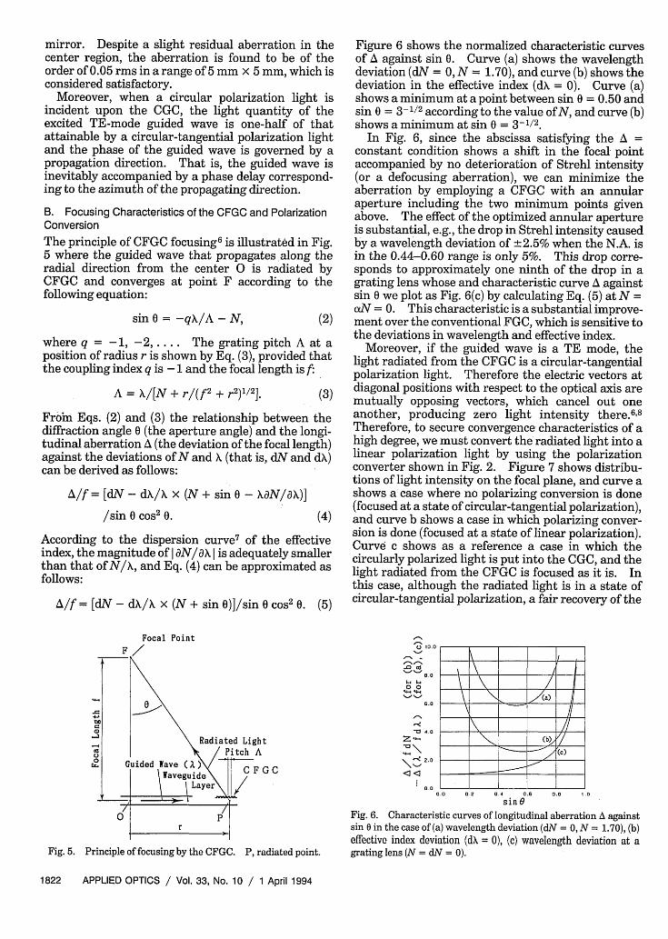
B. Focusing Characteristics of the CFGC and PolarizationConversionThe principle of CFGC focusing6 is illustrated in Fig.5 where the guided wave that propagates along theradial direction from the center 0 is radiated byCFGC and converges at point F according to thefollowing equation:
sin 0 = -qX/A - N (2)
where q = -1, -2..... The grating pitch A at aposition of radius r is shown by Eq. (3), provided thatthe coupling index q is -1 and the focal length is f:
A = X/[N + r/(f2 + r2)1/2 ]. (3)
Froim Eqs. (2) and (3) the relationship between thediffraction angle 0 (the aperture angle) and the longi-tudinal aberration A (the deviation of the focal length)against the deviations of N and (that is, dN and dX)can be derived as follows:
A/f = [dN - dX/X x (N + sin 0 - XaN/A)]
/sin 0 cos2 0. (4)
According to the dispersion curve7 of the effectiveindex, the magnitude of I aN/A I is adequately smallerthan that of N/X, and Eq. (4) can be approximated asfollows:
A/f = [dN - dX/X x (N + sin 0)3/sin 0 cos 2 0. (5)
Focal Point
Figure 6 shows the normalized characteristic curvesof A against sin 0. Curve (a) shows the wavelengthdeviation (dN = 0, N = 1.70), and curve (b) shows thedeviation in the effective index (dX = 0). Curve (a)shows a minimum at a point between sin 0 = 0.50 andsin 0 = 3-1/2 according to the value of N, and curve (b)shows a minimum at sin 0 = 3-1/2.
In Fig. 6, since the abscissa satisfying the A =constant condition shows a shift in the focal pointaccompanied by no deterioration of Strehl intensity(or a defocusing aberration), we can minimize theaberration by employing a CFGC with an annularaperture including the two minimum points givenabove. The effect of the optimized annular apertureis substantial, e.g., the drop in Strehl intensity causedby a wavelength deviation of +2.5% when the N.A. isin the 0.44-0.60 range is only 5%. This drop corre-sponds to approximately one ninth of the drop in agrating lens whose and characteristic curve A againstsin 0 we plot as Fig. 6(c) by calculating Eq. (5) at N =xN = 0. This characteristic is a substantial improve-
ment over the conventional FGC, which is sensitive tothe deviations in wavelength and effective index.
Moreover, if the guided wave is a TE mode, thelight radiated from the CFGC is a circular-tangentialpolarization light. Therefore the electric vectors atdiagonal positions with respect to the optical axis aremutually opposing vectors, which cancel out oneanother, producing zero light intensity there.6 8
Therefore, to secure convergence characteristics of ahigh degree, we must convert the radiated light into alinear polarization light by using the polarizationconverter shown in Fig. 2. Figure 7 shows distribu-tions of light intensity on the focal plane, and curve ashows a case where no polarizing conversion is done(focused at a state of circular-tangential polarization),and curve b shows a case in which polarizing conver-sion is done (focused at a state of linear polarization).Curve c shows as a reference a case in which thecircularly polarized light is put into the CGC, and thelight radiated from the CFGC is focused as it is. Inthis case, although the radiated light is in a state ofcircular-tangential polarization, a fair recovery of the
0.0 0.2 0.4 0.6 0.0 I.
sin 0Fig. 6. Characteristic curves of longitudinal aberration A againstsin 0 in the case of (a) wavelength deviation (dN = 0, N = 1.70), (b)effective index deviation (dX = 0), (c) wavelength deviation at agrating lens (N = dN = 0).
U ,0.0
.0 10
.0D t0
'.0
Z 4~ .0
\ '< Z. 0
PaC
Fig. 5. Principle of focusing by the CFGC. P radiated point.
1822 APPLIED OPTICS / Vol. 33, No. 10 / 1 April 1994
I.0
0.8
p 0.6
._
. 0.4
0.2
-3.0 -2.0 -1.0 0.0 1.0
- Axis ( - Axis) ( )2. I2.0 3.0
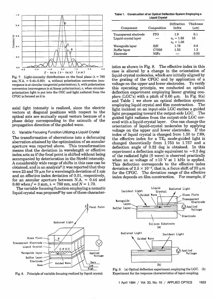
Fig. 7. .Light-intensity distributions on the focal plane ( = 780nm; N.A. = 0.44-0.60): a, without polarization conversion (con-vergence is at circular-tangential polarization); b, with polarizationconversion (convergence is at linear polarization); c, when circular-polarization light is put into the CGC and light radiated from theCFGC is focused as it is.
axial light intensity is realized, since the electricvectors at diagonal positions with respect to theoptical axis are mutually equal vectors because of aphase delay corresponding to the azimuth of thepropagation direction of the guided wave.
C. Variable Focusing Function Utilizing a Liquid Crystal
The transformation of aberrations into a defocusingaberration attained by the optimization of an annularaperture was reported above. This transformationmeans that the deviation in wavelength or effectiveindex acts as if the focal point is shifted without beingaccompanied by deterioration in the Strehl intensity.A considerably wide range of shifts in this case can beobtained, and in an analysis6 it was reported that theywere 23 and 79 jim for a wavelength deviation of 1 nmand an effective index deviation of 0.01, respectively,for an annular aperture between N.A. = 0.44 and0.60 when f = 3 mm, = 780 nm, and N= 1.70.
The variable focusing function employing a nematicliquid crystal was proposed9 by use of these character-
F Focal Point
Radiated Light
Glass Plate /
Transparent ElectrodeLiquid Crystal
Waveguide layer Applied
Buffer Layer VoltageElectrode
Base o foui ed by l u c\_High
Fig. 8. Principle of variable focusing realized by liquid crystal.
Table 1. Construction of an Optical Deflection System Employing aLiquid Crystal
Diffraction ThicknessComponent Composition Index (ALm)
Transparent electrode ITO 1.9 0.1Liquid-crystal layer - = 1.69 15
no= 1.50Waveguide layer SiN 1.78 0.8Buffer layer C7059 1.53 1.3Electrode NiFe - 0.05
istics as shown in Fig. 8. The effective index in thiscase is altered by a change in the orientation ofliquid-crystal molecules, which are initially aligned bythe grating of the CFGC and by application of avoltage on the upper and lower electrodes. To verifythis operating principle, we conducted an opticaldeflection experiment employing linear grating cou-plers (LGC's) with a pitch of 0.60 pLm. In Fig. 9(a)and Table 1 we show an optical deflection systememploying liquid crystal and film construction. Thelight incident on an input-side LGC excites a guidedlight propagating toward the output-side LGC. Theguided light radiates from the output-side LGC, cov-ered with a liquid-crystal layer. One can change theorientation of liquid-crystal molecules by applyingvoltage on the upper and lower electrodes. If theindex of liquid crystal is changed from 1.50 to 169;the effective index for a TEO mode-guided light ischanged theoretically from 1.753 to 1.757 and adeflection angle of 0.32 deg is obtained. In thisexperiment a deflection angle equivalent to 0.2 degof the radiated light (S wave) is observed practicallywhen an ac voltage of ± 10 V at 1 kHz is applied.This deflection corresponds to the effective indexdeviation of 2.5 x 10⁻³, that is, a focus shift of 20 pumfor the CFGC. The deviation range of the effectiveindex depends on film construction. For example, if
LiquidIncident Light Crystal
\Guided Wave \
WaveguideLayer.
Buffer Layer-
Radiated Light
/ - Glass PlateTransparent
Electrode
3 AppliedVoltage
Elec trode
Silicon Substrate(a)
Radiated Light Incident Light
AppliedVoltage
(b)Fig. 9. (a) Optical deflection experiment employing the LGC. (b)Experiment for the response characteristics of input coupling.
1 April 1994 / Vol. 33, No. 10 / APPLIED OPTICS 1823
b
i X
_-tl,/''t =~~~~~~~~~~~
=-;a 2ffl =XX~~~~~~~~~~~~~~~~
AL o_ _ \ -z -,, �/, -, A 7 � I / � A X ��
o.o
1:
n:
-120.0 -
10' 102 10' 10' 10
Frequency (z)
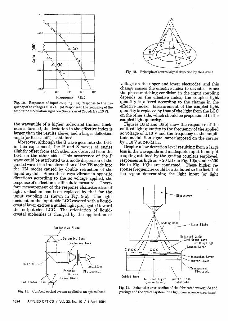
Fig. 10. Responses of input coupling. (a) Response to the fre-quency of acvoltage (±10 V). (b) Response to the frequency of theamplitude modulation signal on the carrier of 240 MHz (± 10 V).
the waveguide of a higher index and thinner thick-ness is formed, the deviation in the effective index islarger than the results above, and a larger deflectionangle (or focus shift) is obtained.
Moreover, although the S wave goes into the LGCin this experiment, the P and S waves at anglesslightly offset from each other are observed from theLGC on the other side. This occurrence of the Pwave could be attributed to a mode dispersion of theguided wave (the transformation of the TE mode intothe TM mode) caused by double refraction of theliquid crystal. Since these rays vibrate in oppositedirections according to the ac voltage applied, theresponse of deflection is difficult to measure. There-fore measurement of the response characteristics oflight deflection has been replaced by that for theinput coupling as shown in Fig. 9(b). The lightincident on the input-side LGC covered with a liquid-crystal layer excites a guided light propagated towardthe output-side LGC. The orientation of liquid-crystal molecules is changed by the application of
Reflective Plane
Objective LensCondenser Lens
Fig. 12. Principle of control signal detection by the CFGC.
voltage on the upper and lower electrodes, and thischange causes the effective index to deviate. Sincethe phase-matching condition in the input couplingdepends on the effective index, the coupled lightquantity is altered according to the change in theeffective index. Measurement of the coupled lightquantity is replaced by that of the light from the LGCon the other side, which should be proportional to thecoupled light quantity.
Figures 10(a) and 10(b) show the responses of theemitted light quantity to the frequency of the appliedac voltage of 10 V and the frequency of the ampli-tude modulation signal superimposed on the carrierby ±lOVat 240 MHz.
Despite a low detection level resulting from a largeloss in the waveguide and inadequate input-to-outputcoupling attained by the grating couplers employed,responses as high as 20 kHz in Fig. 10(a) and 500Hz in Fig. 10(b) are confirmed. These higher re-sponse frequencies could be attributed to the fact thatthe region determining the light input (or light
C
Hal f
Collimator lens
PinholeScreen
Laser Diode
Amplifier
Photosensor
Guided
Fig. 11. Confocal optical system applied to an optical head.
Incident Light Quartz Glass(He-Ne Laser) Substrate
Fig 13. Schematic cross section of the fabricated waveguide andgratings and the optical system for a light convergence experiment.
1824 APPLIED OPTICS / Vol. 33, No. 10 / 1 April 1994
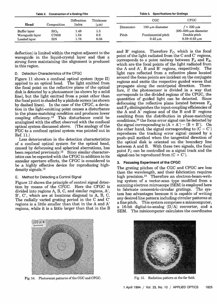
Table 2. Construction of a Grating Film
Diffraction ThicknessHead Composition Index (>m)
Buffer layer SiO2 1.49 1.3Waveguide layer C7059 1.54 0.6Loaded layer SiN 1.78 0.05
deflection) is limited within the region adjacent to thewaveguide in the liquid-crystal layer and that astrong force maintaining the alignment is producedin this region.
D. Detection Characteristics of the CFGC
Figure 11 shows a confocal optical system (type II)applied to an optical head. The light emitted fromthe focal point on the reflective plane of the opticaldisk is detected by a photosensor (as shown by a solidline), but the light emitted from a point other thanthe focal point is shaded by a pinhole screen (as shownby dashed lines). In the case of the CFGC, a devia-tion in the light-emitting point causes a disturbancein the phase-matching condition and produces lowercoupling efficiency.' 0 This disturbance could beanalogized with the effect observed with the confocaloptical system discussed above. (The analogy of theFGC to a confocal optical system was pointed out inRef. 11.)
Less deterioration in the detection characteristicsof a confocal optical system for the optical head,caused by defocusing and spherical aberrations, hasbeen reported previously.12 Since similar character-istics can be expected with the CFGC in addition to itsannular aperture effects, the CFGC is considered tobe a highly effective device for reproducing high-density signals.' 3
E. Method for Detecting a Control Signal
Figure 12 shows the principle of control signal detec-tion by means of the CFGC. Here the CFGC isdivided into regions A, B, C, and similar regions, A',B', C', which are at locations diagonal to A, B, C.The radially varied grating period in the C and C'regions is a little smaller than that in the A and A'regions, while it is a little larger than that in the B
Fig. 14. Photoresist patterns of the CGC and CFGC.
Table 3. Specifications for Gratings
CGC CFGC
Dimension 100-LLm diameter f = 330 pum300-500-p.m diameter
Pitch Fundamental pitch Double pitch0.42 pLm 0.59-0.63 pum
and B' regions. Therefore Fc, which is the focalpoint of the light radiated from the C and C' regions,corresponds to a point midway between FA and FB,which are the focal points of the light radiated fromthe A and A', B and B' regions, respectively. Thelight rays reflected from a reflective plane locatedaround the focus points are incident on the conjugateregions and excite the respective guided waves thatpropagate along the centripetal direction. There-fore, if the photosensor is divided in a way thatcorresponds to the divided regions of the CFGC, thequantities of guided light can be detected. Sincedefocusing the reflective plane located between FAand FB distinguishes the input-coupling efficiencies ofthe A and A' regions and of the B and B' regionsresulting from the distribution in phase-matchingconditions,'( the focus error signal can be detected bythe signal corresponding to (A + A') - (B + B'). Onthe other hand, the signal corresponding to (C - C')reproduces the tracking error signal caused by apush-pull method when the tangential direction ofthe optical disk is oriented on the boundary linebetween A and B. With these two signals, the focalpoint Fc can be controlled on a signal track and thesignal can be reproduced from (C + C').
3. Focusing Experiment of the CFGCThe grating pitches of the CGC and CFGC are lessthan the wavelength, and their fabrication requireshigh precision.14 Therefore an electron-beam-writ-ing system of a vector-scan type modified from ascanning electron microscope (SEM) is employed hereto fabricate concentric-circular gratings. The sys-tem has advantages because it is capable of writingany desired line pattern including circular patterns ata fine pitch. This system comprises a minicomputer,a 16-bit digital-to-analog (D/A) converter, and aSEM. The minicomputer calculates the coordinates
Fig. 15. Radiation pattern at the far field.
1 April 1994 / Vol. 33, No. 10 / APPLIED OPTICS 1825
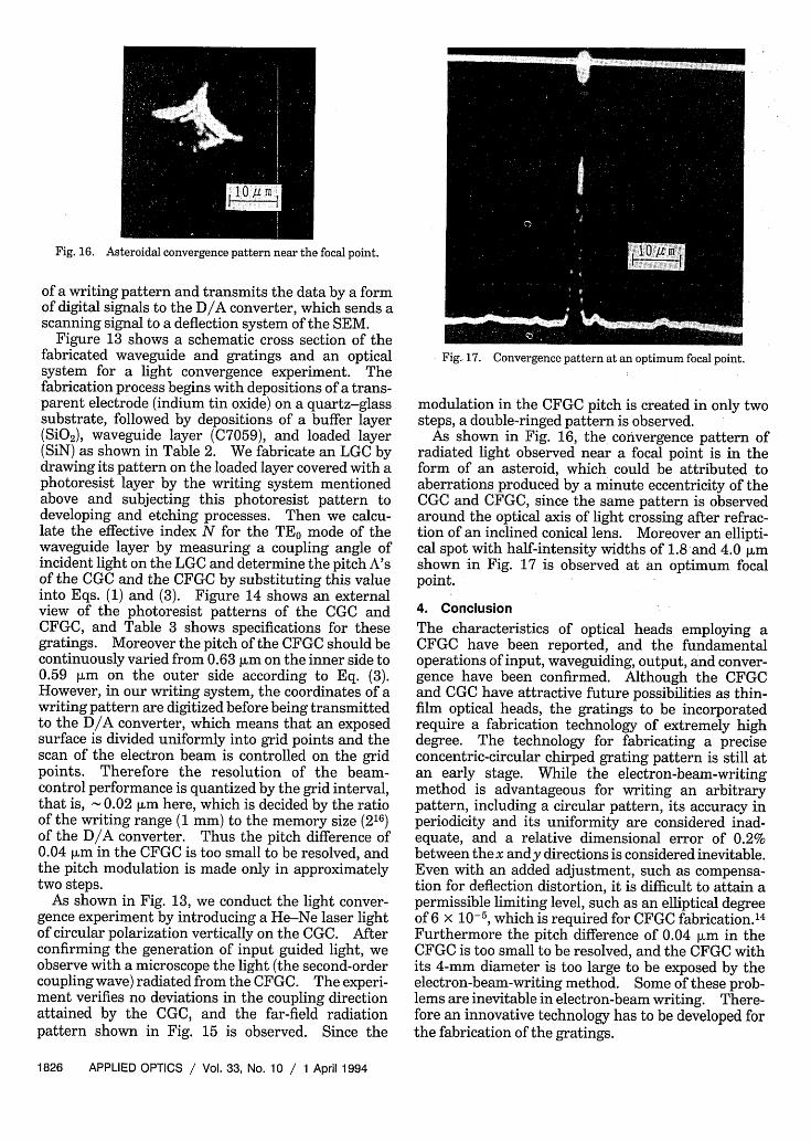
Fig. 16. Asteroidal convergence pattern near the focal point.
of a writing pattern and transmits the data by a formof digital signals to the D/A converter, which sends ascanning signal to a deflection system of the SEM.
Figure 13 shows a schematic cross section of thefabricated waveguide and gratings and an opticalsystem for a light convergence experiment. Thefabrication process begins with depositions of a trans-parent electrode (indium tin oxide) on a quartz-glasssubstrate, followed by depositions of a buffer layer(SiO2), waveguide layer (C7059), and loaded layer(SiN) as shown in Table 2. We fabricate an LGC bydrawing its pattern on the loaded layer covered with aphotoresist layer by the writing system mentionedabove and subjecting this photoresist pattern todeveloping and etching processes. Then we calcu-late the effective index N for the TEO mode of thewaveguide layer by measuring a coupling angle ofincident light on the LGC and determine the pitch A'sof the CGC and the CFGC by substituting this valueinto Eqs. (1) and (3). Figure 14 shows an externalview of the photoresist patterns of the CGC andCFGC, and Table 3 shows specifications for thesegratings. Moreover the pitch of the CFGC should becontinuously varied from 0.63 pum on the inner side to0.59 plm on the outer side according to Eq. (3).However, in our writing system, the coordinates of awriting pattern are digitized before being transmittedto the D/A converter, which means that an exposedsurface is divided uniformly into grid points and thescan of the electron beam is controlled on the gridpoints. Therefore the resolution of the beam-control performance is quantized by the grid interval,that is, 0.02 [lm here, which is decided by the ratioof the writing range (1 mm) to the memory size (216)of the D/A converter. Thus the pitch difference of0.04 [lm in the CFGC is too small to be resolved, andthe pitch modulation is made only in approximatelytwo steps.
As shown in Fig. 13, we conduct the light conver-gence experiment by introducing a He-Ne laser lightof circular polarization vertically on the CGC. Afterconfirming the generation of input guided light, weobserve with a microscope the light (the second-ordercoupling wave) radiated from the CFGC. The experi-ment verifies no deviations in the coupling directionattained by the CGC, and the far-field radiationpattern shown in Fig. 15 is observed. Since the
Fig., 17. Convergence pattern at an optimum focal point.
modulation in the CFGC pitch is created in only twosteps, a double-ringed pattern is observed.
As shown in Fig. 16, the convergence pattern ofradiated light observed near a focal point is in theform of an asteroid, which could be attributed toaberrations produced by a minute eccentricity of theCGC and CFGC, since the same pattern is observedaround the optical axis of light crossing after refrac-tion of an inclined conical lens. Moreover an ellipti-cal spot with half-intensity widths of 1.8 and 4.0 gmshown in Fig. 17 is observed at an optimum focalpoint.
4. ConclusionThe characteristics of optical heads employing aCFGC have been reported, and the fundamentaloperations of input, waveguiding, output, and conver-gence have been confirmed. Although the CFGCand CGC have attractive future possibilities as thin-film optical heads, the gratings to be incorporatedrequire a fabrication technology of extremely highdegree. The technology for fabricating a preciseconcentric-circular chirped grating pattern is still atan early stage. While the electron-beam-writingmethod is advantageous for writing an arbitrarypattern, including a circular pattern, its accuracy inperiodicity and its uniformity are considered inad-equate, and a relative dimensional error of 0.2%between thex andy directions is considered inevitable.Even with an added adjustment, such as compensa-tion for deflection distortion, it is difficult to attain apermissible limiting level, such as an elliptical degreeof 6 x 10⁻⁵, which is required for CFGC fabricationsFurthermore the pitch difference of 0.04 m in theCFGC is too small to be resolved, and the CFGC withits 4-mm diameter is too large to be exposed by theelectron-beam-writing method. Some of these prob-lems are inevitable in electron-beam writing. There-fore an innovative technology has to be developed forthe fabrication of the gratings.
1826 APPLIED OPTICS / Vol. 33, No. 10 / 1 April 1994
With this background the authors recently pro-posed a new method of forming a circular-gratingpattern by utilizing the interference of conical waves.' 5To improve the convergence characteristics of theCFGC, the authors will develop this method further,and their results will be reported separately in afuture paper.
The authors express sincerest gratitude to Y. Horiand F. Sogawa for helpful cooperation and guidancewith the electron-beam-writing and thin-film-form-ing technologies and to Y. Taketomi for valuableadvice.
References1. D. Heitmann and C. Ortiz, "Calculation and experimental
verification of two-dimensional focusing grating couplers,"IEEE J. Quantum Electron. QE-17, 1257-1263 (1981).
2. S. Ura, T. Suhara, H. Nishihara, and J. Koyama, "A focusinggrating for an integrated-optic disk pickup device," Trans. Soc.Electr. Commun. Eng. J68-C, 803-811 (1985); "An integrated-optic disk pickup device," IEEE J. Lightwave Technol. LT-4,913-918 (1986).
3. S. Ura, T. Suhara, and H. Nishihara, "Aberration characteris-tics of a focusing grating coupler in an integrated-optic diskpickup device," Appl. Opt. 26, 4777-4782 (1987).
4. S. Nishiwaki, S. Uchida, J. Asada, and T. Yonezawa, "Super-resolutional waveguide type optical head (1)," in ExtendedAbstracts of the 50th Spring Meeting (Japan Society of AppliedPhysics and Related Societies, Tokyo, 1989), paper 30a-PB-4,p. 972; "Development of superresolutional waveguide typeoptical head (1)," in Extended Abstracts of the Autumn Meeting(Japan Society for Precision Engineering, Tokyo, 1989), pp. 97-98; S. Nishiwaki, Y. Taketomi, S. Uchida, T. Tomita, T.Yonezawa, and S. Mizuno, "Optical head apparatus includingconcentric, periodic grating in a waveguide," U.S. patent4,991,919 (12 February 1991).
5. J. Asada, S. Nishiwaki, S. Uchida, and T. Yonezawa, "Super-resolutional waveguide type optical head (3)," in ExtendedAbstracts of the 50th Spring Meeting (Japan Society of AppliedPhysics and Related Societies, Tokyo, 1989), paper 30a-PB-6,p. 973; J. Asada, S. Nishiwaki, S. Uchida, and T. Yonezawa,"Development of superresolutional waveguide type opticalhead (2)," in Extended Abstracts of the Autumn Meeting
(Japan Society for Precision Engineering, Tokyo, 1989), pp. 99-100.
6. S. Nishiwaki, "Analysis of convergence characteristics ofconcentric focusing grating coupler," Jpn. J. Opt. (Kogaku) 19,665-672 (1990) (in Japanese).
7. H. Nishihara, M. Haruna, and T. Suhara, Optical IntegratedCircuits (Ohm, Tokyo, 1985), p. 16.
8. T. Erdogan, 0. King, G. W. Wicks, and D. G. Hall, "Circularlysymmetric operation of a concentric-circle-grating, surface-emitting, AlGaAs/GaAs quantum-well semiconductor laser,"Appl. Phys. Lett. 60, 1921-1923 (1992).
9. J. Asada, S. Nishiwaki, S. Uchida, and T. Yonezawa, "Super-resolutional waveguide type optical head (4)," in ExtendedAbstracts of the 50th Spring Meeting (Japan Society of AppliedPhysics and Related Societies, Tokyo, 1989), paper 30a-PB-7,p. 973.
10. S. Nishiwaki, "Input coupling efficiency of concentric focusinggrating coupler," Jpn. J. Opt. (Kogaku) 20, 222-226 (1991) (inJapanese).
11. T. Suhara and H. Nishihara, "Analysis of read-out response inintegrated-optic disk pickup," Jpn. J. Opt. (Kogaku) 18,82-90(1989) (in Japanese).
12. J. Bratt, "Optics of recording and read-out in optical disksystem," Jpn. J. Appl. Phys. 28, Suppl. 28-3, 103-108 (1989);K. Takei, Y. Kojima, S. Okamoto, K. Chikuma, and T. Toma,"Effects of aberrations in readout response of confocal opticalsystem pickup," in Extended Abstracts of the 59th SpringMeeting (Japan Society of Applied Physics and Related Societ-ies, Tokyo, 1990), paper 29a-PN-9.
13. Y. Yamanaka, H. Hirose, H. Fujii, and K. Kubota, "High-density optical recording by superresolution (II)," in ExtendedAbstracts of the 49th Spring Meeting (Japan Society of AppliedPhysics and Related Societies, Tokyo, 1988), paper 4a-AD-7; Y.Yamanaka, H. Hirose, and K. Kubota, "High-density opticalrecording by superresolution," Jpn. J. Appl. Phys. 28, Suppl.28-3, 197-200 (1989); M. Takano, "Transformation of CD todigital video disk," Nikkei Electron. No. 529, 123-131 (1991)(in Japanese).
14. S. Nishiwaki, "Analysis of aberrations caused by rotationallyasymmetric errors in concentric focusing grating coupler,"Jpn. J. Opt. (Kogaku) 20, 438-444 (1991) (in Japanese).
15. J. Asada, S. Nishiwaki, S. Uchida, F. Tateishi, T. Yonezawa, M.Sunohara, and Y. Shirafuji, "Superresolutional waveguidetype optical head (6)," in Extended Abstracts of the 52th SpringMeeting (Japan Society of Applied Physics and Related Societ-ies, Tokyo, 1991), paper 10p-ZN-4.
1 April 1994 / Vol. 33, No. 10 / APPLIED OPTICS 1827