Embed Size (px)
Citation preview
OPTICAL MEASUREMENT DEVICES
• PRESENTED BY
• POOJA.P.• NIKHIL SHARMA• POOJA PRASAD• RAJNEESH YADU• ANNAPURNA
CHANDRAKAR
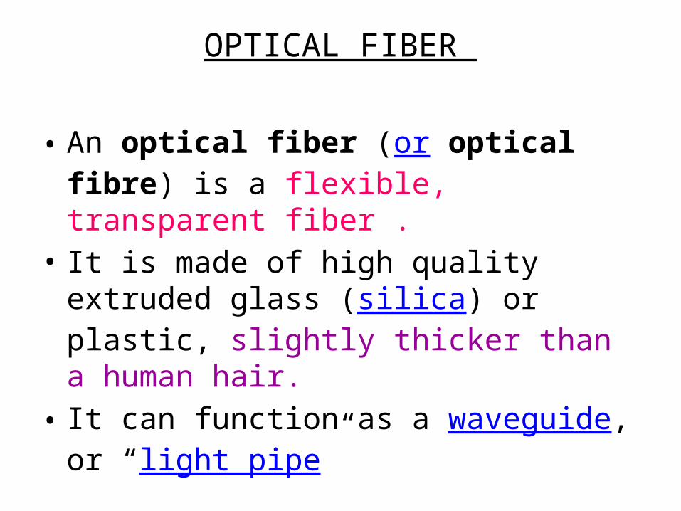
OPTICAL FIBER
• An optical fiber (or optical fibre) is a flexible, transparent fiber .
• It is made of high quality extruded glass (silica) or plastic, slightly thicker than a human hair.
• It can function as a waveguide, or “light pipe”
EQUIPMENTS USED TO MEASURE OPTICAL FIBER
• OPTICAL POWER METER• FUSION SPLICER• OPTICAL FIBER IDENTIFIER• OPTICAL POWER ATTENUATOR• OPTICAL TIME DOMAIN REFLECTOMETER
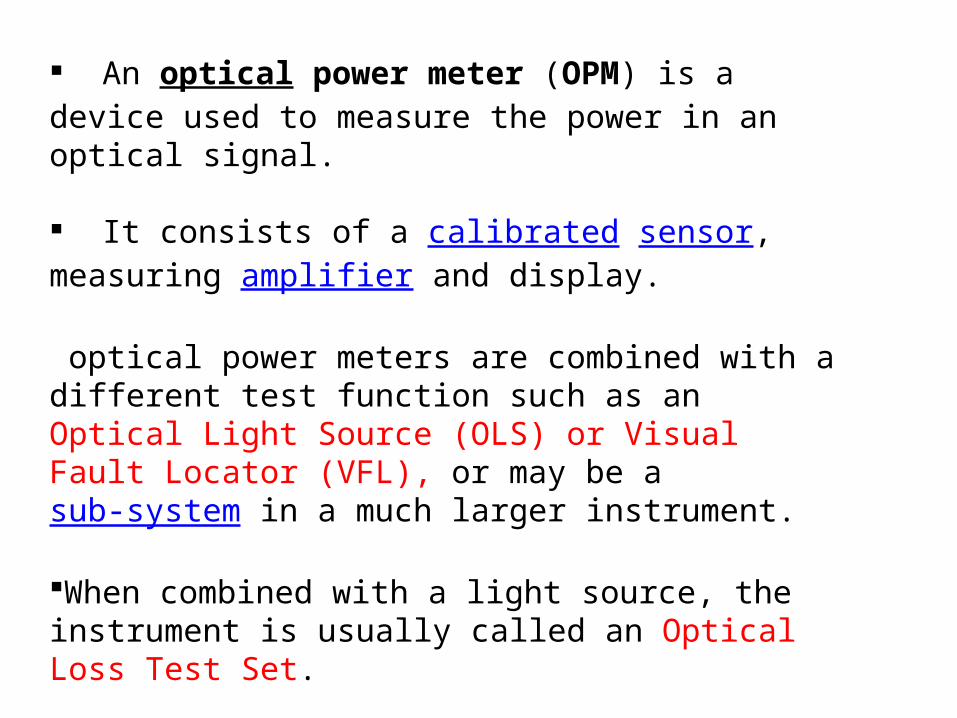
An optical power meter (OPM) is a device used to measure the power in an optical signal.
It consists of a calibrated sensor, measuring amplifier and display.
optical power meters are combined with a different test function such as an Optical Light Source (OLS) or Visual Fault Locator (VFL), or may be a sub-system in a much larger instrument.
When combined with a light source, the instrument is usually called an Optical Loss Test Set.
POWER MEASURING RANGE
• A typical OPM measures accurately under most conditions from about 0 dBm (1 milli Watt) to about -50 dBm (10 nano Watt).
• Above 0 dBm is considered "high power", and specially adapted units may measure up to nearly + 30 dBm ( 1 Watt).
• Below -50 dBm is "low power", and specially adapted units may measure as low as -110 dBm.

FUSION SPLICER
FUSION SPLICING
Fusion splicing is the act of joining two optical fibers end-to-end using heat
The source of heat is usually an electric arc, but can also be a laser, or a gas flame, or a tungsten filament through which current is passed
The process of fusion splicing normally involves using localized heat to melt or fuse the ends of two optical fibers together. The splicing process begins by preparing each fiber end for fusion

PROCESS OF FUSION SPLICING
• Stripping the fiber:-Stripping is the act of removing the protective polymer coating around optical fiber in preparation for fusion splicing. The splicing process begins by preparing both fiber ends for fusion
• Cleaning the fiber:-The bare fibers are cleaned using alcohol and wipes
• Cleaving the fiber:-The fiber is then cleaved using the score-and-break method so that its endface is perfectly flat and perpendicular to the axis of the fiber
OPTICAL FIBER IDENTIFIER
OPTICAL FIBER IDENTIFIER
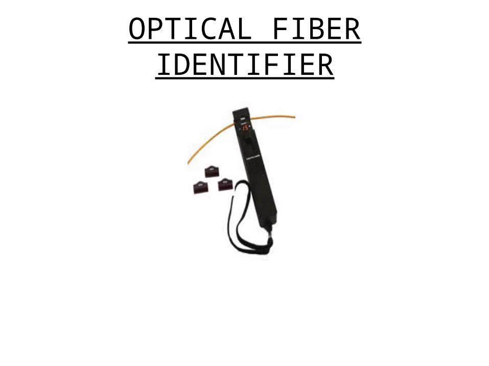
• Fiber identifier is an essential installation and maintenance instrument which can identify the optical fiber by detecting the optical signals transmitted through them
• during this process the fiber optic identifier generate no harm or damage to the fiber cable and it do not need opening the fiber at the splice point for identification or interrupting the service

fiber identifier detects frequency tones at 270Hz, 1KHZ, 2KHZ, when traffic is present on the fiber under test, an audible tone can be heard. In the meantime, it can identify the traffic direction that indicated by LED with illumination.
optical fiber identifier features icacore power display of the fibers low bending loss and high efficient output,easy to replace adaptors,portable, compact size ,small weight and easy-to-use, it is a wonderful and much economic tool used in fiber optic network maintenance
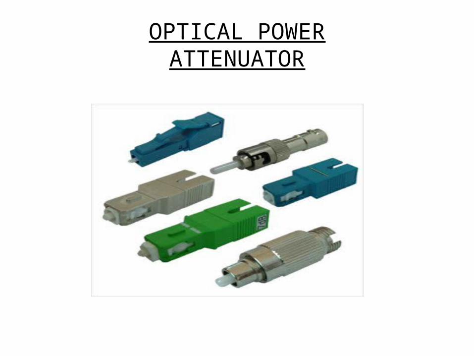
OPTICAL POWERATTENUATOR
MEANING
• Fiber optic attenuators are used in the fiber optic links to reduce the optical power at a certain level
• We supply various kinds of fiber attenuators, including LC, SC, and ST, FC, MU, E2Our fiber optic attenuators are manufactured according to industrial standards, and they are 100% strictly tested during the production
• These fiber optic attenuators are prompt delivery and good prices

TYPES
• SC Fiber Optic Attenuator:- The SC fiber optic attenuators work in the 1250nm to 1625nm range, with attenuation range from 1dB to 30dB op
• LC Fiber Optic Attenuator :-LC fiber optic attenuators work in 1250-1625nm range with optional attenuation value from 1dB to 30dB.
• FC Fiber Optic Attenuator :-these products are used in single mode applications at 1250 to 1625nm wavelength range.
• We supply FC fiber optic attenuators from 1dB to 30dB.

MEANING
• An optical time-domain reflectometer (OTDR) is an optoelectronic instrument used to characterize an optical fiber
• An OTDR injects a series of optical pulses into the fiber under test. It also extracts, from the same end of the fiber, light that is scattered (Rayleigh backscatter) or reflected back from points along the fiber.

TYPES• The common types of OTDR-like test equipment are:• Full-feature OTDR:- Full-feature OTDRs are traditional, optical time
domain reflectometers. They are feature-rich and usually larger
• Hand-held OTDR:-Hand-held (formerly mini) OTDRs and fiber break locators are designed to troubleshoot fiber networks in a field-type environment often using battery power.
• RTU in RFTSs:- The RTU is the testing module of the RFTS described in GR-1295, Generic Requirements for Remote Fiber Testing Systems (RFTSS). An RFTS enables fiber physical plant to be automatically tested from a central location

THANKYOU