Embed Size (px)
Citation preview

Optical scanning cryptography for securewireless transmission
Ting-Chung Poon, Taegeun Kim, and Kyu Doh
We propose a method for secure wireless transmission of encrypted information. By use of an encryptionkey, an image or document is optically encrypted by optical heterodyne scanning and hence encryptionis performed on the fly. We call this technique optical scanning cryptography. The output of theheterodyne encrypted signal is at radio frequency and can be directly sent through an antenna to a securesite for digital storage to be prepared for decryption. In the secure site, an identical optical scanningsystem to that used for encryption is used, together with a decryption key, to generate an electrical signal.The electrical signal is then processed and sent to a computer to be used for decryption. Utilizing thestored information received from the encryption stage and the electrical information from the secure site,a digital decryption unit performs a decryption algorithm. If the encryption key and the decryption keyare matched, the decryption unit will decrypt the image or document faithfully. The overall cryptosys-tem can perform the incoherent optical processing counterpart of the well-known coherent double-randomphase-encoding technique. We present computer simulations of the idea. © 2003 Optical Society ofAmerica
OCIS codes: 110.0110, 090.0090.
1. Introduction
Cryptography is the practice and study of encryptionand decryption.1 The method of quantum cryptog-raphy is based on the use of one of the quantumproperties of a photon, i.e., polarization, and has thepotential to be absolutely unbreakable.2,3 However,current practical considerations introduce securityloopholes, which eavesdroppers can exploit. Indeed,totally secure communications are far from a reality.On the classical front, optical cryptography, which isalso based on photons, has a long-standing history.Recent progress in the development of optical compo-nents and systems and their increasingly improvedtechnical performance suggest that optical cryptog-raphy has significant potential for security applica-tions. Indeed, a plethora of publications in recent
T.-C. Poon �[email protected]� is with the Optical Image ProcessingLaboratory, Bradley Department of Electrical and Computer En-gineering, Virginia Polytechnic Institute and State University,Blacksburg, Virginia 24061. T. Kim is with the Department ofOptical Engineering, Sejong University, 98 Kunja-Dong,Kwangjin-Ku, Seoul 143-747, Korea. K. Doh is with the Depart-ment of Telecommunication Engineering, Hankuk Aviation Uni-versity, 200-1 Hwajeon-dong, Goyang-city, Korea.
Received 30 December 2002; revised manuscript received 11June 2003.
0003-6935�03�326496-08$15.00�0© 2003 Optical Society of America
6496 APPLIED OPTICS � Vol. 42, No. 32 � 10 November 2003
years have dealt with secure systems that use opticalmethods.4–12
One of the reasons for using optical encryption isthat information, such as images, that needs to beencrypted exists already in the optical domain. An-other reason is that optical encryption, as opposed toelectronic or digital encryption, can provide manydegrees of freedom for securing information. Whenlarge volumes of information, such as a three-dimensional �3-D� object, are to be encrypted,11,13 theuse of optical encryption methods is probably themost logical choice. Whereas most optical encryp-tion techniques are optically coherent, an incoherentoptical technique for encryption was proposed recent-ly.12 However, inverse filtering which spoils thesignal-to-noise ratio, has been used for decryption.Nevertheless, in general incoherent optical tech-niques possess many advantages over their coherentcounterparts, such as a better signal-to-noise ratioand insensitivity to misalignment of optical ele-ments.14
In this paper we propose a novel incoherent opticalmethod for encryption. In particular, we have in-vestigated the optically incoherent implementation ofdouble-random phase encoding. The method isbased on optical heterodyne scanning and has manyadvantages besides being an incoherent technique.Other advantages are as follows: �1�. Because it isan optical scanning method, incoherent objects, such

as printed documents, can be directly processed with-out the need for using spatial light modulators toconvert an incoherent image to a coherent image as inthe existing coherent techniques cited above. In-deed, the proposed system can perform real-time oron-the-fly encryption. For example, a standard la-ser scanner, once it is modified according to the pro-posed technique, can become an on-the-fly opticalencryption system. �2�. As the output signal is aheterodyne electrical signal and hence the encryptedinformation is riding on a heterodyne frequency or acarrier frequency as in communications, the signalcan be immediately radiated for wireless transmis-sion to a secure site for storage and subsequent en-cryption. �3�. The technique is easily extendible toencryption of 3-D information, as it is based on opticalscanning holography.15 In Section 2 we briefly dis-cuss optical heterodyne scanning, which is the coretechnique of our proposed cryptosystem. In Sections3 and 4 we discuss ways in which to perform encryp-tion and decryption, respectively, with the proposedoptical scanning technique. In Section 5 we discusshow the proposed encryption system can implementthe so-called double-random phase encoding incoher-ently; i.e., we can work with incoherent objects di-
rectly. We provide in Section 6 some computersimulations of the ideas presented. Finally, in Sec-tion 7 we give summaries and provide some conclud-ing remarks.
2. Optical Heterodyne Scanning
The cryptosystem includes identical optical systemsin the encryption and the decryption stages. Weshall therefore describe the optical system in the en-cryption stage. The optical system is a two-pupilheterodyne scanning system, which has been usedextensively for incoherent image processing,14–17
scanning holographic recording,15 3-D microsco-py,18,19 and, more recently, optical recognition of 3-Dobjects and optical remote sensing.20–22 Inasmuchas a mathematical description of the two-pupil opticalsystem was recently worked out in detail,20 we shallbriefly describe the system’s operation and presentsome of the results pertinent to the present study.
The encryption stage illustrated in Fig. 1 shows thebasic optical heterodyne scanning system. Two pu-pils, p1�x, y� and p2�x, y�, located in the front focalplanes of the lens, are illuminated by two broad laserbeams of temporal frequencies �0 and �0 � �, respec-tively. The two beams are then combined by a beam
Fig. 1. Optical system for encryption and decryption �I0�x, y� is the document to be encrypted, p1�x, y� is the encryption key in theencryption stage, and p2�x, y� is the decryption key in the decryption stage�: R’s, electronic multipliers; LPFs, low-pass filters; BPF@�,bandpass filter tuned at �; PDs, photodetectors.
10 November 2003 � Vol. 42, No. 32 � APPLIED OPTICS 6497

splitter, BS, and used for two-dimensional �2-D� scan-ning of the object, I0�x, y�, located a distance zc awayfrom the back focal plane of the lens. The photode-tector collects all the light transmitted by the object�or all the scattered light if the object is diffuselyreflecting�. As the two laser beams are of differenttemporal frequencies, the photodetector will have aheterodyning current at frequency � as one of itsoutputs �with the other output as a baseband signal�.After electronic tuning at �, the heterodyne current,i�c �x, y�, can be isolated and expressed as20
i�c � x, y; zc� � Re�i�p
� x, y; zc�exp� j�t��, (1)
where we have adopted the convention for phasor �pas ��x, y, t� Re��p�x, y, t�exp� j�t��, and Re� � de-notes the real part of the bracketed quantity. i�p
�x,y; zc� is the output phasor, which contains the ampli-tude and the phase information on the heterodynecurrent and constitutes the scanned and processedversion of the object I0�x, y�. It has been shown thatthe spectrum of i�p
is related to the spectrum of I0�x,y� as follows20:
�i�p� x, y; zc�� � �I0� x, y; zc��OTF��kx, ky; zc�,
(2)
where � denotes the 2-D Fourier-transform opera-tion and is defined as �u�x, y�� �� u�x,y�exp� jkxx � jkyy�dxdy U�kx, ky�, kx and ky denotethe spatial frequencies, and uppercase function Udenotes the transform of lowercase function u.OTF��kx, ky; zc� is the optical transfer function �OTF�of the heterodyne scanning system and can be ex-pressed in terms of the two processing pupils as20
OTF��kx, ky; zc� � exp�jzc
2k0�kx
2 � ky2��
� �� p1*� x , y � p2�x �f
k0kx,y �
fk0
ky�� exp�j
zc
f� x kx � y ky��dx dy , (3)
where k0 is the wave number of the laser and f is thefocal length of the lens. Finally, in writing Eq. �2�we deliberately inserted zc into the argument of I0 asa parameter to emphasize that the input and outputrelationship in Eq. �2� refers to a single plane, z zc.Using Eq. �2� transforms Eq. �1� into
i�c � x, y; zc� � Re�i�p
� x, y; zc�exp� j�t��
� Re���1�I0� x, y; zc��
� OTF��kx, ky; zc��exp� j�t��, (4)
where ��1 denotes an inverse 2-D Fourier transform.In Section 3 below, we use Eq. �4�, together with Eq.�3�, to discuss encryption and decryption concepts.Equation �4� is a general equation that describes theoutput heterodyne current of the two-pupil opticalscanning system. The output current is the scanned
and processed version of the scanned input I0�x, y; zc�.The processing elements are the two pupil functions,p1�x, y� and p2�x, y�. In other words, by modifyingthe pupils we will have different processed outputs.
Inspecting Eq. �4�, we can see that the processedinformation is carried by a temporal carrier at fre-quency �, and, if � is chosen to be in the radio-frequency domain �which can be done easily throughthe use of acousto-optic modulators23�, the processedinformation can be readily radiated to a secure sitefor further processing, as shown in Fig. 1. After thesecure site receives the processed information froman antenna, the information is further processed elec-tronically as shown in Fig. 1; i.e., the incoming signalis multiplied by cos��t� and sin��t� and low-pass fil-tered, yielding two signals, ic and is, respectively, asgiven by20
ic� x, y; zc� � Re���1�I0� x, y; zc�� � OTF���,(5a)
is� x, y; zc� � Im���1�I0� x, y; zc�� � OTF���,(5b)
where Im� � denotes the imaginary part of the brack-eted quantity. If we now add the expression givenby Eqs. �5� in the following fashion: i�x, y; zc� ic�x,y; zc� � jis�x, y; zc�, we have a complex expressionfrom which the full amplitude and phase are avail-able:
i� x, y; zc� � ��1�I0� x, y; zc�� � OTF��. (6)
In passing, it is interesting to point out that the re-sults described above can be used to process intensityimages with complex point-spread functions,17 as theOTF in the expression can be made complex in gen-eral.
3. Encryption
To perform encryption on input I0�x, y; zc� located adistance zc away from the back focal plane of the lensat the encryption stage, in general we can manipulatethe two pupils, p1�x, y� and p2�x, y�. As a simpleexample, we let p2�x, y� ��x, y�, a pinhole, and keepp1�x, y� as is. We call p1�x, y� an encryption key andzc a coding distance. Under these conditions theOTF of the system becomes, according to Eq. �3�,
OTF��kx, ky; zc� � exp��jzc
2k0�kx
2 � ky2��
� p1*��fk0
kx,�fk0
ky� , (7)
and Eq. �6� then becomes
i� x, y; zc� � ��1��I0� x, y; zc��exp��jzc
2k0
� �kx2 � ky
2��p1*��fk0
kx,�fk0
ky�� ,
(8)
6498 APPLIED OPTICS � Vol. 42, No. 32 � 10 November 2003
where i�x, y; zc� is the coded or encrypted image andcan be stored by the digital computer. Note that thespectrum of I0�x, y; zc� is multiplied by two terms.As the product of the object’s spectrum with the termexp��j�zc�2k0��kx
2 � ky2�� translates to holographic
recording of the object located zc away from the lens,20
we can interpret Eq. �8� as holographic information ofthe object �or a hologram of the object� encrypted orcoded by p1. This idea of coding holographic infor-mation was investigated by Schilling and Poon in thecontext of optical scanning holography.24 Now, if wegroup the object’s spectrum with p1 first, we can in-terpret it as the object’s being encrypted or coded byp1 and then the encrypted information holographi-cally recorded; i.e., we obtain a hologram of the en-crypted document.
4. Decryption
After the object has been coded or encrypted, weneed to decode or decrypt it. To do this we turn tothe optical system at the secure site. Again, notethat the optical system is the same, except in thechoice of pupils, and the laser beams now scan apinhole as an object, i.e., I0�x, y; zd� ��x, y; zd�,located a distance zd away from the back focal planeof the lens at the decryption stage. We call zd adecoding distance. This time, though, the switch,as shown in Fig. 1, is on the output of the opticalsystem at the secure site. Results in Eq. �6� can beapplied again, but with zc replaced by zd. Now wechoose, for example, p1�x, y� ��x, y�, a pinhole, andkeep p2�x, y� as is. We call p2�x, y� a decryptionkey. This choice of pupils gives the following OTF,according to Eq. �3�:
OTF��kx, ky; zd� � exp�jzd
2k0�kx
2 � ky2��
� p2� fk0
kx,f
k0ky� . (9)
Using Eq. �6� and the fact that �I0�x, y; zd�� 1, wehave
i� x, y; zd� � ��1�exp�jzd
2k0�kx
2 � ky2��
� p2� fk0
kx,f
k0ky�� . (10)
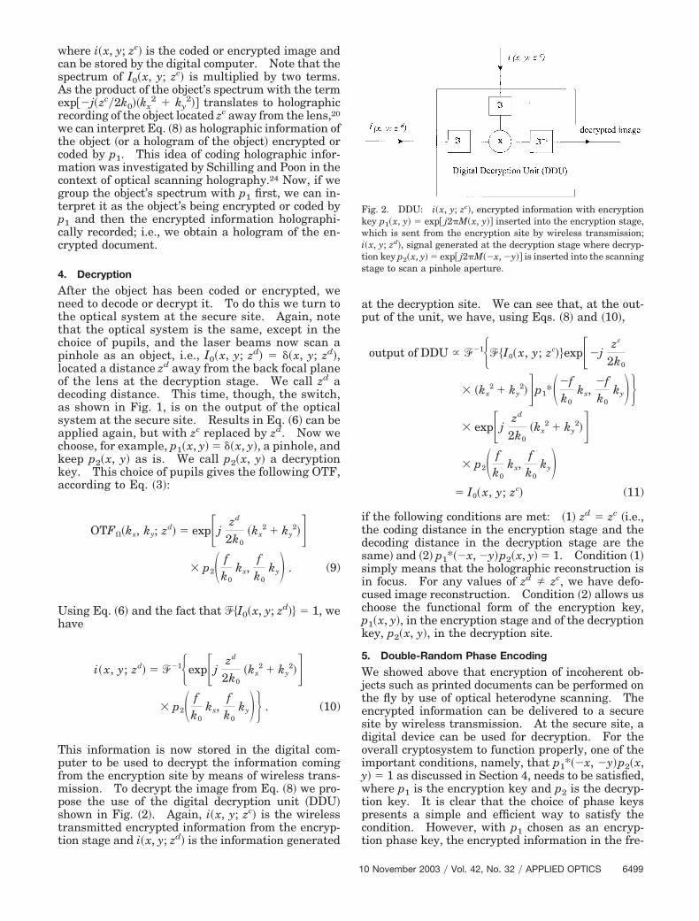
This information is now stored in the digital com-puter to be used to decrypt the information comingfrom the encryption site by means of wireless trans-mission. To decrypt the image from Eq. �8� we pro-pose the use of the digital decryption unit �DDU�shown in Fig. �2�. Again, i�x, y; zc� is the wirelesstransmitted encrypted information from the encryp-tion stage and i�x, y; zd� is the information generated
at the decryption site. We can see that, at the out-put of the unit, we have, using Eqs. �8� and �10�,
output of DDU � ��1��I0� x, y; zc��exp��jzc
2k0
� �kx2 � ky
2��p1*��fk0
kx,�fk0
ky��� exp�j
zd
2k0�kx
2 � ky2��
� p2� fk0
kx,f
k0ky�
� I0� x, y; zc� (11)
if the following conditions are met: �1� zd zc �i.e.,the coding distance in the encryption stage and thedecoding distance in the decryption stage are thesame� and �2� p1*��x, �y�p2�x, y� 1. Condition �1�simply means that the holographic reconstruction isin focus. For any values of zd � zc, we have defo-cused image reconstruction. Condition �2� allows uschoose the functional form of the encryption key,p1�x, y�, in the encryption stage and of the decryptionkey, p2�x, y�, in the decryption site.
5. Double-Random Phase Encoding
We showed above that encryption of incoherent ob-jects such as printed documents can be performed onthe fly by use of optical heterodyne scanning. Theencrypted information can be delivered to a securesite by wireless transmission. At the secure site, adigital device can be used for decryption. For theoverall cryptosystem to function properly, one of theimportant conditions, namely, that p1*��x, �y�p2�x,y� 1 as discussed in Section 4, needs to be satisfied,where p1 is the encryption key and p2 is the decryp-tion key. It is clear that the choice of phase keyspresents a simple and efficient way to satisfy thecondition. However, with p1 chosen as an encryp-tion phase key, the encrypted information in the fre-
Fig. 2. DDU: i�x, y; zc�, encrypted information with encryptionkey p1�x, y� exp� j2�M�x, y�� inserted into the encryption stage,which is sent from the encryption site by wireless transmission;i�x, y; zd�, signal generated at the decryption stage where decryp-tion key p2�x, y� exp� j2�M��x, �y�� is inserted into the scanningstage to scan a pinhole aperture.
10 November 2003 � Vol. 42, No. 32 � APPLIED OPTICS 6499

quency domain presented in Eq. �8� is basically basedon multiplying the Fourier transform of the incoher-ent image by a pure phase function, namely,exp��j�zc�2k0��kx
2 � ky2��p1*���f�k0�kx, ��f�k0�ky�.
Because the phase of the Fourier transform can beretrieved by phase-retrieval techniques, the systemproposed so far is vulnerable to eavesdropping. Toovercome this drawback we explore the so-calleddouble-random phase encoding in the context of op-tical scanning to make the encryption much moresecure.
The technique of double-random phase encodingwas investigated by Refregier and Javidi25 and byGoudail et al.26 The idea is as follows: The coher-ent image f �x, y� to be encrypted is multiplied by arandom phase mask exp� j2�r�x, y��, and the result isthen convolved by a function, which has a phase-onlyFourier transform of the form exp� j2�s�kx, ky��, tobecome an encrypted image ��x, y� f �x,y�exp� j2�r�x, y�� R ��1exp� j2�s�kx, ky���, where Rdenotes 2-D convolution. As r�x, y� and s�kx, ky� arechosen as two independent random functions, onecannot use phase-retrieval techniques to recover theoriginal image just by knowing the encrypted infor-mation only. In this section we describe ways inwhich such double-random phase encoding can beimplemented with the present proposed cryptosys-tem with a simple revision.
Inspecting Eq. �8� we can rewrite the encryptedimage in terms of convolution as
i� x, y; zc� � I0� x, y; zc� � ��1�exp��jzc
2k0�kx
2
� ky2��� � ��1�p1*��f
k0kx,
�fk0
ky�� .
(12)
We can implement double-random phase encoding ifwe have the original image I0�x, y; zc� multiplied by arandom phase mask and then let encryption key p1�x,y� become a random phase function. We can multi-ply the original image by a random phase mask sim-ply by directly putting a phase mask exp� j2�r�x, y��immediately in front of the original image beforescanning in the encryption system. Hence thedouble-random phase-encoding version of the pro-posed scanning system has an encrypted image of theform
i� x, y; zc� � I0� x, y; zc�exp� j2�r� x, y��
� ��1�exp��jzc
2k0�kx
2 � ky2���
� ��1�p1*��fk0
kx,�fk0
ky�� . (13)
Note that this encryption is even more secure thanthe originally proposed double-random phase-
encoding idea, as there is an additional parameter,namely, decoding distance zc, which is still neededfor successful decryption, as we demonstrate in Sec-tion 6.
6. Simulation Results
As a simple example of manipulating the pupil func-tions for encryption, we let p1�x, y� exp� j2�M�x, y��,where M�x, y� is a function of random numbers cho-sen from a uniform distribution on the interval �0.0,1.0�. p2�x, y� ��x, y�, a pinhole, in the encryption
Fig. 3. �a� Original incoherent image; �b� real part of the originaldocument multiplied by a random phase mask exp� j2�r�x, y��placed immediately in front of the document, not shown in Fig. 1;�c� imaginary part of the original document multiplied by a randomphase mask.
6500 APPLIED OPTICS � Vol. 42, No. 32 � 10 November 2003

stage. For this choice of pupil, according to Eq. �13�we have the encrypted image:
i� x, y; zc� � I0� x, y; zc�exp� j2�r� x, y��
� ��1�exp��jzc
2k0�kx
2 � ky2���
� ��1�exp��j2�M��fkx
k0,
�fky
k0��� ,
(14)
where we have assumed that r�x, y� in Eq. �14� isanother function of random numbers, indepen-dently of M�x, y� statistically. Figure 3�a� showsthe original of the image–document I0�x, y; zc� of
dimensions 20 mm � 20 mm to be encrypted. Fig-ures 3�b� and 3�c� show the real and the imaginaryparts of I0�x, y; zc�exp� j2�r�x, y��, respectively.Figure 4 shows the real and the imaginary parts ofthe random-phase encryption key, p1�x, y� exp� j2�M�x, y��, of dimensions 0.8 mm � 0.8 mm,placed in the front focal plane of the lens in theencryption stage. Figure 5 shows the intensity ofthe encrypted document according to Eq. �14� underthe following realistically chosen conditions: focallength f, 10 cm; wavelength of light used �, 0.6 �m;and finally, zc 30 cm.
For decryption, again, we need to gather informa-tion by scanning a pinhole object located zd awayfrom the back focal plane of the lens when the pupilsare p1�x, y� ��x, y�, a pinhole, and p2�x, y� exp� j2�M��x, �y��, satisfying Condition �2� as dis-cussed in Section 5. According to Eq. �10�, thescanned output to be stored in the digital computerbecomes
i� x, y; zd� � ��1�exp�jzd
2k0�kx
2 � ky2��
� exp�j2�M��fkx
k0,
�fky
k0��� . (15)
When the information from Eqs. �14� and �15� is theinput to the DDU, its output, according to Fig. 2, is asfollows:
output of DDU � ��1{�I0� x, y; zc�exp� j2�r� x, y���
� exp��jzc
2k0�kx
2 � ky2��
� exp��j2�M��fkx
k0,
�fky
k0��
� exp�jzd
2k0�kx
2 � ky2��
� exp�j2�M��fkx
k0,
�fky
k0��}
� I0� x, y; zc�exp� j2�r� x, y��, (16)
when zd 30 cm zc. The decrypted output inten-sity is shown in Fig. 6�a�. If decoding distance zd isguessed or chosen incorrectly, say, zd 20 cm, theDDU output is as shown in Fig. 6�b�. We can seethat the introduction of zd gives an extra securitymeasure for double-random phase encoding. Fi-nally, in Fig. 7 we use an incorrect random-phasedecryption key but with the correct decoding distancefor decryption. The key’s random phase is statisti-cally independent of the encryption key. It is obviousthat it does not work.
7. Concluding Remarks
In summary, we have proposed a method for perform-ing optical scanning cryptography. The image–
Fig. 4. Top, real and, bottom, imaginary parts of the encryptionkey, p1�x, y� exp� j2�M�x, y��.
Fig. 5. Intensity of the encrypted document.
10 November 2003 � Vol. 42, No. 32 � APPLIED OPTICS 6501

document to be encrypted is scanned optically.Encryption is performed on the fly by a two-pupiloptical system based on optical heterodyne scanning,and we have shown that double-random phase encod-ing can be implemented incoherently with the pro-posed scanning system. Because the encryptedsignal is in the radio-frequency range, the signal canbe directly sent to an antenna for wireless transmis-sion to a secure site for decryption. In the encryp-tion stage, one of the pupils is a pinhole and the otheris the encryption key of the form of a random phase
function, exp� j2�M�x, y��. In the decryption site anidentical two-pupil optical system is used, but thistime it is scanning a pinhole instead. Again, one ofthe pupils is a pinhole and the other pupil is thedecryption key of the form exp� j2�M��x, �y��. It isimportant to point out that the encryption key andthe decryption key are of the same functional formand hence are actually the same key. As we can see,once we have the encryption key, we can change it toa decryption key by simply flipping it upon the x axisand then upon the y axis. Therefore, in the presentpaper we have discussed symmetric key cryptogra-phy �SKC�; i.e., we are using the same key �the secretkey� to encrypt and decrypt a message. In asymmet-ric key cryptography �AKC�, however, the encryptionkey and the decryption key are not identical.27 AKCis more efficient and reliable, and it is popularly usedin today’s security applications. In light of this, it isimportant that our current proposed method can beextended to work for AKC. So far, we have used asingle pupil as an encryption key in the encryptionstage and also one pupil as a decryption key in thedecryption stage in the proposed two-pupil system.The other pupil in the two stages is just a pinhole. Itmay be possible to find some suitable pupils otherthan those pinholes used in the scanning system insuch a way that the encryption key and the decryp-tion key are different. Instead of the condition thatp1*��x, �y�p2�x, y� 1 be required for decryption inour current SKC scheme, we might come up withother conditions such that AKC can be implementedwith the proposed optical system. It is worthwhilelooking into this possibility.
T.-C. Poon, T. Kim, and K. Doh express their grat-itude for financial support by the National ScienceFoundation �ECS-9810158�, by the Ministry of Infor-mation & Communication of the Republic of Korea�C1-2002-072-0-4�, and by the Regional ResearchCenter of Korea Science and Engineering Foundation�R12-2001-051-00007-0�, respectively. We alsothank the reviewers for helpful comments and sug-gestions.
References1. S. Singh, The Code Book �Random House, New York, 1999�.2. S. Wiesner, “Conjugate coding,” SIGACT News 15�78�, 78–88
�1983�; original manuscript written and circulated in 1970.3. C. H. Benneett, C. Brassard, and A. Ekert, “Quantum cryp-
tography,” Sci. Am. 269�10�, 26–33 �1992�.4. S. Lai and M. A. Neifeld, “Digital wavefront reconstruction and
its applications to image encryption,” Opt. Commun. 178, 283–289 �2000�.
5. B. Wang, C.-C. Sun, W.-C. Su, and A. Chiou, “Shift-toleranceproperty of an optical double-random phase-encoding encryp-tion system,” Appl. Opt. 39, 4788–4793 �2000�.
6. B. Zhu, S. Liu, and Q. Ran, “Optical image encryption based onmultifractional Fourier transforms,” Opt. Lett. 25, 1159–1161�2000�.
7. P. C. Magensen and J. Gluckstad, “Phase-only optical decryp-tion of a fixed mask,” Appl. Opt. 8, 1226–1235 �2001�.
8. H. T. Chang, “Image encryption using separable amplitude-based virtual image and iteratively retrieved phase informa-tion,” Opt. Eng. 40, 2165–2171 �2001�.
Fig. 6. �a� Intensity of a decrypted document when the decryptionkey is matched to the encryption key and the decoding distance isthe same as the coding distance and �b� when the decoding distanceis not the same as the coding distance.
Fig. 7. Intensity of decrypted document when the decryption keyis not the same as the encryption key but the decoding distance ismatched to the coding distance.
6502 APPLIED OPTICS � Vol. 42, No. 32 � 10 November 2003

9. T. Nomura and B. Javidi, “Optical encryption system with abinary key code,” Appl. Opt. 39, 4783–4787 �2000�.
10. O. Matoba and B. Javidi, “Secure ultrafast communicationusing spatial–temporal converters,” Appl. Opt. 39, 2975–2981�2000�.
11. E. Tajahuerce and B. Javidi, “Encrypting three-dimensionalinformation with digital holography,” Appl. Opt. 39, 6595–6601 �2000�.
12. E. Tajahuerce, J. Lancis, B. Javidi, and P. Andres, “Opticalsecurity and encryption with totally incoherent light,” Opt.Lett. 26, 678–680 �2001�.
13. T. Naughton, Y. Frauel, E. Tajahuerce, and B. Javidi, “Com-pression of digital holograms for three-dimensional object re-construction and recognition,” Appl. Opt. 41, 4124–4132�2002�.
14. G. Indebetouw and T.-C. Poon, “Novel approaches of incoher-ent image processing with emphasis on scanning methods,”Opt. Eng. 31, 2159–2167 �1992�.
15. T.-C. Poon, M. Wu, K. Shinoda, and Y. Suzuki, “Optical scan-ning holography,” Proc. IEEE 84, 753–764 �1996�.
16. A. W. Lohmann and W. T. Rhodes, “Two-pupil synthesis ofoptical transfer functions,” Appl. Opt. 17, 1145–1151 �1978�.
17. J. Mait, “Pupil-function design for complex incoherent spatialfiltering,” J. Opt. Soc. Am. A 4, 1185–1193 �1987�.
18. T.-C. Poon, “Three-dimensional fluorescence microscopy by op-
tical scanning holography,” Opt. Photon. News 8�12�, 22–23�1997�.
19. J. Swoger, M. Martinez-Corral, J. Huisken, and E. H. K. Stel-zer, “Optical scanning holography as a technique for high-resolution three-dimensional biological microscopy,” J. Opt.Soc. Am. A 19, 1910–1918 �2002�.
20. T.-C. Poon and T. Kim, “Optical image recognition of three-dimensional objects,” Appl. Opt. 38, 370–381 �1999�.
21. T. Kim, T.-C. Poon, and G. Indebetouw, “Depth detection andimage recovery in remote sensing by optical scanning holog-raphy,” Opt. Eng. 41, 1331–1338 �2002�.
22. B. W. Schilling and G. C. Templeton, “Three-dimensional re-mote sensing by optical scanning holography,” Appl. Opt. 40,5474–5481 �2001�.
23. A. Korpel, “Acousto-optics,” in Applied Solid State Science, R.Wolfe, ed. �Academic, New York, 1972�, Vol. 3, pp. 71–75.
24. B. Schilling and T.-C. Poon, “Real-time pre-processing of ho-lographic information,” Opt. Eng. 34, 3174–3180 �1995�.
25. P. Refregier and B. Javidi, “Optical image encryption usinginput and Fourier plane random phase encoding,” Opt. Lett.20, 767–769 �1995�.
26. F. Goudail, F. Bollaro, B. Javidi, and P. Refregier, “Influence ofa perturbation in a double phase-encoding system,” J. Opt. Soc.Am. A 15, 2629–2638 �1998�.
27. W. Diffe and M. Hellman, “New directions in cryptography,”IEEE Trans. Inf. Theory IT-22, 644–654 �1976�.
10 November 2003 � Vol. 42, No. 32 � APPLIED OPTICS 6503